US9395033B2 - Projector mount system and method - Google Patents
Projector mount system and method Download PDFInfo
- Publication number
- US9395033B2 US9395033B2 US14/208,177 US201414208177A US9395033B2 US 9395033 B2 US9395033 B2 US 9395033B2 US 201414208177 A US201414208177 A US 201414208177A US 9395033 B2 US9395033 B2 US 9395033B2
- Authority
- US
- United States
- Prior art keywords
- mounting system
- pivotable
- connector
- frame
- stationary body
- Prior art date
- Legal status (The legal status is an assumption and is not a legal conclusion. Google has not performed a legal analysis and makes no representation as to the accuracy of the status listed.)
- Active, expires
Links
- 238000000034 method Methods 0.000 title description 9
- 230000033001 locomotion Effects 0.000 claims description 9
- 238000000926 separation method Methods 0.000 claims description 2
- 230000002401 inhibitory effect Effects 0.000 claims 1
- 230000008859 change Effects 0.000 description 7
- 230000026058 directional locomotion Effects 0.000 description 2
- 230000006978 adaptation Effects 0.000 description 1
- 230000008901 benefit Effects 0.000 description 1
- 238000010276 construction Methods 0.000 description 1
- 238000004519 manufacturing process Methods 0.000 description 1
- 230000004048 modification Effects 0.000 description 1
- 238000012986 modification Methods 0.000 description 1
- 230000004044 response Effects 0.000 description 1
- 230000000717 retained effect Effects 0.000 description 1
Images


Classifications
-
- F—MECHANICAL ENGINEERING; LIGHTING; HEATING; WEAPONS; BLASTING
- F16—ENGINEERING ELEMENTS AND UNITS; GENERAL MEASURES FOR PRODUCING AND MAINTAINING EFFECTIVE FUNCTIONING OF MACHINES OR INSTALLATIONS; THERMAL INSULATION IN GENERAL
- F16M—FRAMES, CASINGS OR BEDS OF ENGINES, MACHINES OR APPARATUS, NOT SPECIFIC TO ENGINES, MACHINES OR APPARATUS PROVIDED FOR ELSEWHERE; STANDS; SUPPORTS
- F16M11/00—Stands or trestles as supports for apparatus or articles placed thereon Stands for scientific apparatus such as gravitational force meters
- F16M11/02—Heads
- F16M11/04—Means for attachment of apparatus; Means allowing adjustment of the apparatus relatively to the stand
- F16M11/06—Means for attachment of apparatus; Means allowing adjustment of the apparatus relatively to the stand allowing pivoting
- F16M11/12—Means for attachment of apparatus; Means allowing adjustment of the apparatus relatively to the stand allowing pivoting in more than one direction
- F16M11/121—Means for attachment of apparatus; Means allowing adjustment of the apparatus relatively to the stand allowing pivoting in more than one direction constituted of several dependent joints
- F16M11/123—Means for attachment of apparatus; Means allowing adjustment of the apparatus relatively to the stand allowing pivoting in more than one direction constituted of several dependent joints the axis of rotation intersecting in a single point, e.g. by using gimbals
-
- F—MECHANICAL ENGINEERING; LIGHTING; HEATING; WEAPONS; BLASTING
- F16—ENGINEERING ELEMENTS AND UNITS; GENERAL MEASURES FOR PRODUCING AND MAINTAINING EFFECTIVE FUNCTIONING OF MACHINES OR INSTALLATIONS; THERMAL INSULATION IN GENERAL
- F16M—FRAMES, CASINGS OR BEDS OF ENGINES, MACHINES OR APPARATUS, NOT SPECIFIC TO ENGINES, MACHINES OR APPARATUS PROVIDED FOR ELSEWHERE; STANDS; SUPPORTS
- F16M11/00—Stands or trestles as supports for apparatus or articles placed thereon Stands for scientific apparatus such as gravitational force meters
- F16M11/02—Heads
- F16M11/04—Means for attachment of apparatus; Means allowing adjustment of the apparatus relatively to the stand
- F16M11/06—Means for attachment of apparatus; Means allowing adjustment of the apparatus relatively to the stand allowing pivoting
- F16M11/12—Means for attachment of apparatus; Means allowing adjustment of the apparatus relatively to the stand allowing pivoting in more than one direction
- F16M11/125—Means for attachment of apparatus; Means allowing adjustment of the apparatus relatively to the stand allowing pivoting in more than one direction for tilting and rolling
-
- F—MECHANICAL ENGINEERING; LIGHTING; HEATING; WEAPONS; BLASTING
- F16—ENGINEERING ELEMENTS AND UNITS; GENERAL MEASURES FOR PRODUCING AND MAINTAINING EFFECTIVE FUNCTIONING OF MACHINES OR INSTALLATIONS; THERMAL INSULATION IN GENERAL
- F16M—FRAMES, CASINGS OR BEDS OF ENGINES, MACHINES OR APPARATUS, NOT SPECIFIC TO ENGINES, MACHINES OR APPARATUS PROVIDED FOR ELSEWHERE; STANDS; SUPPORTS
- F16M11/00—Stands or trestles as supports for apparatus or articles placed thereon Stands for scientific apparatus such as gravitational force meters
- F16M11/02—Heads
- F16M11/04—Means for attachment of apparatus; Means allowing adjustment of the apparatus relatively to the stand
- F16M11/06—Means for attachment of apparatus; Means allowing adjustment of the apparatus relatively to the stand allowing pivoting
- F16M11/12—Means for attachment of apparatus; Means allowing adjustment of the apparatus relatively to the stand allowing pivoting in more than one direction
- F16M11/14—Means for attachment of apparatus; Means allowing adjustment of the apparatus relatively to the stand allowing pivoting in more than one direction with ball-joint
-
- F—MECHANICAL ENGINEERING; LIGHTING; HEATING; WEAPONS; BLASTING
- F16—ENGINEERING ELEMENTS AND UNITS; GENERAL MEASURES FOR PRODUCING AND MAINTAINING EFFECTIVE FUNCTIONING OF MACHINES OR INSTALLATIONS; THERMAL INSULATION IN GENERAL
- F16M—FRAMES, CASINGS OR BEDS OF ENGINES, MACHINES OR APPARATUS, NOT SPECIFIC TO ENGINES, MACHINES OR APPARATUS PROVIDED FOR ELSEWHERE; STANDS; SUPPORTS
- F16M13/00—Other supports for positioning apparatus or articles; Means for steadying hand-held apparatus or articles
- F16M13/02—Other supports for positioning apparatus or articles; Means for steadying hand-held apparatus or articles for supporting on, or attaching to, an object, e.g. tree, gate, window-frame, cycle
- F16M13/027—Ceiling supports
-
- E—FIXED CONSTRUCTIONS
- E04—BUILDING
- E04B—GENERAL BUILDING CONSTRUCTIONS; WALLS, e.g. PARTITIONS; ROOFS; FLOORS; CEILINGS; INSULATION OR OTHER PROTECTION OF BUILDINGS
- E04B9/00—Ceilings; Construction of ceilings, e.g. false ceilings; Ceiling construction with regard to insulation
- E04B9/006—Ceilings; Construction of ceilings, e.g. false ceilings; Ceiling construction with regard to insulation with means for hanging lighting fixtures or other appliances to the framework of the ceiling
-
- F—MECHANICAL ENGINEERING; LIGHTING; HEATING; WEAPONS; BLASTING
- F21—LIGHTING
- F21V—FUNCTIONAL FEATURES OR DETAILS OF LIGHTING DEVICES OR SYSTEMS THEREOF; STRUCTURAL COMBINATIONS OF LIGHTING DEVICES WITH OTHER ARTICLES, NOT OTHERWISE PROVIDED FOR
- F21V21/00—Supporting, suspending, or attaching arrangements for lighting devices; Hand grips
- F21V21/02—Wall, ceiling, or floor bases; Fixing pendants or arms to the bases
- F21V21/03—Ceiling bases, e.g. ceiling roses
Definitions
- This invention generally relates to system methods for mounting electronic devices.
- Electronic projectors are generally devices used to project an image onto a vertical surface, such as a screen or wall. They are often hung from ceilings or placed on a support surface such as a desk.
- Embodiments of the invention include a mounting system for a projector.
- the mounting system includes a stationary body and a gimbal assembly to connect to a projector.
- the mounting system includes a plurality of supports connected to the stationary body and the gimbal assembly.
- the lengths of the supports are independently adjustable to adjust a tilt angle and a roll angle of a projector connected to the gimbal with respect to the stationary body.
- the mounting system includes a stationary body and a frame to connect to a projector.
- the mounting system includes a plurality of supports and at least one pivotable connector connected to the stationary body and the frame.
- the lengths of the supports are independently adjustable to adjust a tilt angle and a roll angle of a projector connected to the frame with respect to the stationary body.
- the pivotable connectors prevent movement about a yaw axis of the frame relative to the stationary body, and are configured such that their lengths can change in order to accommodate the tilt and/or roll adjustments of the frame.
- Embodiments of the invention also include methods of using such mounting systems.
- FIG. 1 is a perspective view of a mounting system 1 accordance with an embodiment of the invention.
- FIG. 2 is a perspective view of a mounting system in accordance with an embodiment of the invention depicting certain angles.
- FIG. 3 is an exploded perspective view of a mounting system in accordance with an embodiment of the invention.
- FIG. 4 is a side plan view of a support adjusted to a first length in accordance with an embodiment of the invention, and the support adjusted to a second length, and the support adjusted to a third length.
- FIG. 5 is an exploded perspective view of a gimbal assembly in accordance with an embodiment of the invention.
- FIG. 6 is a side cut-away view of a gimbal assembly in accordance with an embodiment of the invention.
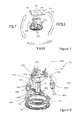
- FIG. 7 is a perspective view of a mounting system in accordance with another embodiment of the invention depicting certain angles.
- FIG. 8 is a perspective view of the mounting system of FIG. 7 in a dis-assembled state.
- FIG. 9A is a side plan view of a support adjusted to a first length in accordance with an embodiment of the invention.
- FIG. 9B is a side plan view of a support adjusted to a second length in accordance with an embodiment of the invention.
- FIG. 9C is a side plan view of a support adjusted to a third length in accordance with an embodiment of the invention.
- FIG. 10 is a cross-sectional view of the mounting system of FIG. 7 .
- FIG. 11 is a perspective view of a portion of the mounting system of FIG. 7 in a dis-assembled state.
- FIG. 12 is a cross-sectional view of the mounting system of FIG. 11 in an assembled state.
- FIG. 1 is a perspective view of a mounting system 10 for a projector in accordance with an embodiment of the invention.
- the mounting system 10 allows for fine adjustments of the tilt and roll angle of the projector to desirably align an image projected from the projector with a vertical surface such as a screen.
- References to tilt, roll, and yaw angles herein will refer to the directional movements depicted in FIG. 2 (note that tilt and roll are symmetrical and therefor interchangeable for purposes of this disclosure).
- embodiments of the mounting system 10 can include a stationary body 20 and a gimbal assembly 30 to connect to a projector.
- the stationary body 20 and the gimbal assembly 30 can be connected to each other via a plurality of supports 40 A,B,C.
- the mounting system 10 can include a first support 40 A having a first end 44 A connected to the stationary body 20 and a second end 46 A connected to the gimbal assembly 30 , a second support 40 B having a first end 44 B connected to the stationary body 20 and a second end 46 B connected to the gimbal assembly 30 , and a third support 40 C having a first end 44 C connected to the stationary body 20 and a second end 46 C connected to the gimbal assembly 30 .
- a length of the first, second, and third supports 40 A,B,C is adjustable independently of the length of the other of the first, second, and third supports 40 A,B,C. Accordingly, such a system is useful for adjusting a tilt angle and a roll angle of a projector connected to the gimbal assembly 30 with respect to the stationary body 20 .
- the supports 40 can assume any useful orientation.
- the first, second, and third supports 40 A,B,C are located equidistantly about a circumference of the mounting system 10 .
- the stationary body 20 has a generally vertical longitudinal axis and the first, second, and third supports 40 A,B,C each have a longitudinal axis, and the longitudinal axes of the first, second, and third supports 40 A,B,C are skewed relative the generally vertical longitudinal axis.
- each support 40 is pivotably connected to the stationary body 20 to allow pivoting of the first end of the support relative to the stationary body 20 about a generally horizontal axis.
- the second end 46 of each support 40 is pivotably connected to the gimbal assembly 30 to allow pivoting of the second end of the support relative to the gimbal assembly 30 about a generally horizontal axis.
- Such pivotable connections can include a rivet or a bolt.
- the length of the supports 40 can be adjusted by any suitable method.
- FIGS. 4A-C depict a support 40 adjusted to assume three different respective lengths.
- the length of the supports 40 can be infinitely adjusted between the minimum and the maximum lengths provided by the support.
- the length of the supports 40 adjusts in a linear path by rotating a dial 50 .
- the dial 50 may be threadingly engaged with first and second legs 60 , 62 , such that rotation of the dial linearly extends or retracts the first and second legs from the dial.
- the supports 40 include a turnbuckle.
- the stationary body 20 and gimbal assembly 30 are further connected by a guide member 70 .
- the guide member 70 has a generally spherical outer surface 80 .
- the guide member 70 can provide support to the connection yet allow desired tilt and roll angle adjustments.
- the stationary body 20 has a generally cylindrical member 90 ( FIG. 3 ) extending into an interior of the guide member 70 and the gimbal assembly 30 is in apposition to the generally spherical outer surface 80 .
- the gimbal assembly 30 can include a first portion 100 and a second portion 102 connected (e.g., with fasteners 106 ) about the guide member 70 to retain it.
- the guide member 70 is keyed against rotation with respect to the cylindrical member 90 .
- the cylindrical member can include splines 110 along an exterior surface to interact with splines 112 on the interior surface of the guide member to key the guide against rotation, as shown in FIG. 3 .
- the guide includes a groove 120 along its generally spherical outer surface, the groove 120 sized to receive a ball 130 carried by the gimbal assembly 30 .
- a spring 140 can be used to bias the ball into the groove 120 .
- the mounting system 10 is configured to only allow for tilt and roll angle adjustments and vertical adjustments, and resists other adjustments.
- the stationary body 20 may be configured to rest on a horizontal support surface or to be attached to a ceiling.
- a first plate 150 is connected to the stationary body 20 and configured to be in apposition to a generally horizontal support surface.
- the first plate is configured to be attached to a ceiling. In some embodiments, it can include on or more apertures 154 for receiving a fastener.
- the gimbal assembly 30 can be configured to connect to the projector in any suitable fashion.
- the gimbal assembly 30 includes a second plate 160 configured to connect to a projector.
- the second plate can include one or more plate slots 170 to adjustably connect to a projector with a fastener.
- Embodiments of the invention also include methods of using mounting systems.
- the method can include the step of providing a mounting system for a projector having a stationary body and a gimbal assembly connected by a plurality of supports having independently adjustable lengths, and adjusting a length of at least one support to change the tilt or roll angle of the mounting system.
- FIG. 7 is a perspective view of a mounting system 200 for a projector in accordance with another embodiment of the invention.
- the mounting system 200 limits movement about a yaw axis and allows for fine adjustments of the tilt and roll angle of the projector to desirably align an image projected from the projector with a vertical surface such as a screen.
- the mounting system 200 permits a small amount of travel in the vertical direction. References to tilt, roll, and yaw angles for the mounting system 200 will refer to the directional movements depicted in FIG. 7 (note that tilt and roll are symmetrical and therefor interchangeable for purposes of this disclosure)
- embodiments of the mounting system 200 can include a stationary body 210 and a frame 220 to connect to a projector.
- the stationary body 210 and the frame 220 can be connected to each other via a plurality of supports 230 A,B,C and at least one, such as two, pivotable connectors 240 A,B.
- the mounting system 200 can include a first support 230 A having a first end 250 A connected to the stationary body 210 and a second end 260 A connected to the frame 220 , a second support 230 B having a first end 250 B connected to the stationary body 210 and a second end 260 B connected to the frame 220 , a third support 230 C having a first end (not visible) connected to the stationary body 210 and a second end 260 C connected to the frame 220 , a first pivotable connector 240 A between the stationary body 210 and the frame 220 , and a second pivotable connector 240 B between the stationary body 210 and the frame 220 .
- the first end of the third support 230 C is substantially similar to the first ends 250 A,B of the supports 230 A,B.
- a length of the first, second, and third supports 230 A,B,C is adjustable independently of the length of the other of the first, second, and third supports 230 A,B,C.
- the stationary body 210 can be retained in a fixed position while frame 220 can be rolled and/or tilted relative to the fixed stationary body 210 . Accordingly, such a system is useful for adjusting a tilt angle and a roll angle of a projector connected to the frame 220 with respect to the stationary body 210 .
- the first and second pivotable connectors 240 A,B are configured to limit and/or inhibit yaw movement of the frame 220 with respect to the stationary body 210 .
- each pivotable connector 240 is configured such that its length changes so as to accommodate the tilt and roll of the frame 220 with respect to the stationary body 210 .
- the supports 230 can assume any useful orientation.
- the first, second, and third supports 230 A,B,C are located equidistantly about a perimeter of the mounting system 200 .
- the stationary body 210 has a generally vertical longitudinal axis and the first, second, and third supports 230 A,B,C each have a longitudinal axis, and the longitudinal axes of the first, second, and third supports 230 A,B,C are skewed relative the generally vertical longitudinal axis.
- connection of all the supports 230 A,B,C to both the stationary body 210 and the frame 220 are not included. What is included is an exemplary description of the connections, as illustrated in FIG. 10 , between the stationary body 210 and the support 230 B, and between the frame 220 and the support 230 B. It should be appreciated that the connection of the supports 230 A,C to the stationary body 210 and the frame 220 , although not shown or described, will be substantially similar to the following description of the connection of the support 230 B to the stationary body 210 and the frame 220 .
- the first end 250 B of the support 230 B is pivotably connected to the stationary body 210 to allow pivoting of the first end 250 B of the support 230 B relative to the stationary body 210 about a generally horizontal axis.
- the first end 250 B of the support 230 B is secured to the stationary body 210 by a cap 270 B. (Although not shown, cap 270 A is similarly used for securing the first end 250 A of the support 230 A to the stationary body 210 .)
- the second end 260 B of each support 230 B is pivotably connected to the frame 220 to allow pivoting of the second end 260 B of the support 230 B relative to the frame 220 about a generally horizontal axis.
- the second end 260 B of each support 230 B is pivotably connected to the frame 220 by encasing the second end 260 B in the frame 220 .
- the length of the supports 230 can be adjusted by any suitable method.
- FIGS. 9A-C depict a support 230 adjusted to assume three different respective lengths.
- the length of the supports 230 can be infinitely adjusted between the minimum and the maximum lengths provided by the support 230 .
- the length of the supports 230 adjusts in a linear path by rotating a dial 280 .
- the dial 280 may be threadingly engaged with first and second legs 290 , 300 , such that rotation of the dial 280 linearly extends or retracts the first and second legs 290 , 300 from the dial 280 .
- the first and second legs 290 and 300 include threaded shanks having threads in a direction opposite each other.
- the threaded shanks extend into the dial 280 such that when the dial 280 is rotated, both the first and second legs 290 and 300 extend or retract in unison.
- the frame 220 is substantially parallel to the top of the stationary body 210 . Adjusting the length of any one or more of the supports 230 will change the tilt and/or roll angle of the frame 220 proportional to the magnitude of the change in the length.
- the supports 230 include a turnbuckle.
- the supports 230 are load bearing supports.
- the mounting system 200 includes a connector 310 extending from the stationary body 210 .
- the connector 310 is a protrusion extending from the stationary body 210 .
- the connector 310 is configured for supporting a lateral force.
- the first pivotable connector 240 A has a first end 320 A connected to the connector 310 and a second end 330 A connected to the frame 220
- the second pivotable connector 240 B has a first end 320 B connected to the connector 310 and a second end 330 B connected to the frame 220
- the first ends 320 of each pivotable connector 240 are pivotably connected to the connector 310
- one or more lateral extensions (e.g., rivets) 340 extending laterally from the connector 310 can be used for connecting the first ends 320 of each pivotable connector 240 to the connector 310 in a manner such that each pivotable connector 240 can pivot independently about the extensions 340 .
- each pivotable connector 240 are pivotably connected to the frame 220 . In certain embodiments, the second end 330 of each pivotable connector 240 is pivotably connected to the frame 220 by encasing the second end 330 in the frame 220 .
- the first ends 320 A,B of the pivotable connectors 240 A,B include a Y-link 350 A,B having an opening 360 A,B.
- Each opening 360 A,B is defined at least in part by first and second sides 370 A,B and 380 A,B of the Y-links 350 A,B arranged in an opposed spaced apart relationship with each other.
- the first sides 370 A,B of the Y-links 350 A,B respectively include apertures 390 A,B for connecting the first sides 370 A,B of the Y-links 350 A,B to the connector 310 .
- the second sides 380 A,B of the Y-links 350 A,B respectively include apertures for connecting the second sides 380 A,B of the Y-links 350 A,B to the connector 310 .
- FIG. 11 it should be noted that only aperture 392 A in the second side 380 A of the Y-link 350 A is visible, and that the aperture in the second side 380 B of the Y-link 350 B is not visible.
- at least a portion of the connector 310 can extend through the openings 360 A,B in the Y-links 350 A,B of the pivotable connectors 240 A,B.
- At least one of the first and second sides 370 and 380 of at least one of the pivotable connector 240 is connected to the connector 310 .
- two or more of the first and/or seconds sides 370 and 380 of one and/or both pivotable connector 240 are connected to the connector 310 .
- the first and second sides 370 and 380 of the pivotable connector 240 are pivotal connected to the connector 310 .
- a lateral extension 340 extending through the aperture 390 can be used for pivotably connecting the first and second sides 370 and 380 of the pivotable connector 240 to opposing sides of the connector 310 .
- the first end 320 A,B of the pivotable connector 240 A,B is considered a pivotable end defined by the opposed first and second sides 370 A,B of the Y-link 350 A,B.
- yaw movement (or rotation) of the pivotable connectors 240 with respect to the stationary body 210 is limited.
- yaw movement of the frame 220 to which the second end 330 of the pivotable connector 240 is connected is also limited.
- the Y-link 350 is an anti-rotation system for the frame 220 , generally limiting rotation about a yaw axis (e.g., a generally vertical axis).
- the pivotable connectors 240 are configured such that a length of the first and second pivotable connector 240 A,B can change independently of the length of the other of the first and second pivotable connector 240 A,B. Accordingly, the length of each of the first and second pivotable connector 240 A,B changes to accommodate the tilt and roll of the frame 220 with respect to the stationary body 210 .
- the pivotable connectors 240 A,B can include Y-links 350 A,B and shanks 400 A,B. As shown in FIG. 11 , and as previously described, the pivotable ends of the Y-links 350 A,B as defined at least in part by the first and second sides 370 A,B and 380 A,B define at least a portion of the first ends 320 A,B of the pivotable connectors 240 A,B. Accordingly, in some embodiments, the first end 320 A,B of the pivotable connector 240 A,B, which is also the pivotable end of the Y-link 350 A,B, is pivotally connected to the connector 310 .
- each Y-link 350 A,B can include a sliding section 410 A,B.
- a pivotable end of the shank 400 A,B defines at least a portion of the second end 330 A,B of the pivotable connector 240 A,B.
- the second end 330 A,B of the pivotable connector 240 A,B which is also the pivotable end of the shank 400 A,B, can be pivotably connected to the frame 220 .
- each shank 400 A,B can include a sliding section 420 A,B.
- the sliding section 410 A,B of the Y-link 350 A,B and the sliding section 420 A,B of the shank 400 A,B are configured for sliding engagement with each other such that a length of the pivotable connector 240 A,B is changeable in response to the tilt and roll movement of the frame 220 .
- the sliding section 410 of the Y-link 350 is configured for slideable engagement with the sliding section 420 of the shank 400 .
- the sliding section 410 A,B of the Y-link 350 A,B includes one or more apertures 430 A,B configured for slideably receiving the sliding section 420 A,B of the shank 400 A,B.
- the sliding section 420 A,B of the shank 400 A,B extends through the aperture 430 A,B in the sliding section 410 A,B of the Y-link 350 A,B.
- the length of the pivotable connector 240 A,B can change as the sliding section 420 A,B of the shank 400 A,B extends and slides through the aperture 430 A,B in the sliding section 410 A,B of the Y-link 350 A,B.
- the sliding section 420 A,B of the shank 400 A,B includes a jam-nut 440 A,B around a threaded portion of the shank 400 A,B opposite the pivotable end of the shank 400 A,B which, as previously described, is also the second end 330 A,B of the pivotable connector 240 A,B.
- the jam-nut 440 A,B inhibits dislodgement of the sliding section 420 A,B of the shank 400 A,B from the sliding section 410 A,B of the Y-link 350 A,B. Accordingly, separation of the Y-link 350 A,B and the shank 400 A,B from each other is inhibited or prevented.
- the length of the sliding section 420 A,B of the shank 400 A,B extending through the jam-nut 440 A,B is adjustable for limiting the distance traveled by the shank 400 A,B through the aperture 430 A,B in the sliding section 410 A,B of the Y-link 350 A,B.
- the frame 220 can include opposing first and second plates 450 and 460 configured for encapsulating the second ends 260 A,B,C of each support 230 A,B,C and the second ends 330 A,B of each pivotable connector 240 A,B between the first and second plates 450 and 460 .
- FIG. 10 shows the second end 260 B of the support 230 B encased between the first and second plates 450 and 460 and pivotably connected to the frame 220 .
- the second plate 460 is configured to connect to the projector.
- the frame 220 can be configured to connect to the projector in any suitable fashion. It should be noted that although not shown in FIG. 10 , the second ends 260 A,C of the supports 230 A,C are similarly encased as second end 260 B of support 230 B is between the first and second plates 450 and 460 and pivotably connected to the frame 220 .
- the stationary body 210 may be configured to rest on a horizontal support surface or to be attached to a ceiling.
- a first plate 470 is connected to the stationary body 210 and configured to be in apposition to a generally horizontal support surface.
- the first plate 470 is configured to be attached to a ceiling.
- the first plate 470 can include on or more apertures 480 for receiving a fastener.
- Embodiments of the invention also include methods of using the mounting systems.
- the method can include the step of providing the mounting system having the stationary body and the frame to which a projector is attached.
- the stationary body and the frame are connected to each other by a plurality of supports having independently adjustable lengths and a plurality of pivotable connectors.
- the tilt and/or roll of the projector attached to the frame can be changed relative to the stationary body by adjusting a length of at least one support.
- the pivotable connectors limit the yaw movement (or the rotation about the yaw axis) of the frame relative to the stationary body, and are configured such that their lengths can change independently of each other for accommodating the tilt and/or roll adjustments of the frame.
Landscapes
- Engineering & Computer Science (AREA)
- General Engineering & Computer Science (AREA)
- Mechanical Engineering (AREA)
- Projection Apparatus (AREA)
Abstract
Description
Claims (26)
Priority Applications (1)
| Application Number | Priority Date | Filing Date | Title |
|---|---|---|---|
| US14/208,177 US9395033B2 (en) | 2013-03-13 | 2014-03-13 | Projector mount system and method |
Applications Claiming Priority (3)
| Application Number | Priority Date | Filing Date | Title |
|---|---|---|---|
| US201361778712P | 2013-03-13 | 2013-03-13 | |
| US201361840077P | 2013-06-27 | 2013-06-27 | |
| US14/208,177 US9395033B2 (en) | 2013-03-13 | 2014-03-13 | Projector mount system and method |
Publications (2)
| Publication Number | Publication Date |
|---|---|
| US20140299738A1 US20140299738A1 (en) | 2014-10-09 |
| US9395033B2 true US9395033B2 (en) | 2016-07-19 |
Family
ID=50625107
Family Applications (1)
| Application Number | Title | Priority Date | Filing Date |
|---|---|---|---|
| US14/208,177 Active 2034-05-21 US9395033B2 (en) | 2013-03-13 | 2014-03-13 | Projector mount system and method |
Country Status (2)
| Country | Link |
|---|---|
| US (1) | US9395033B2 (en) |
| WO (1) | WO2014160011A1 (en) |
Families Citing this family (6)
| Publication number | Priority date | Publication date | Assignee | Title |
|---|---|---|---|---|
| WO2014160011A1 (en) | 2013-03-13 | 2014-10-02 | Ergotron | Projector mount system and method |
| WO2015035009A1 (en) | 2013-09-05 | 2015-03-12 | Ergotron, Inc. | Projector adjustment mechanism |
| USD754242S1 (en) * | 2013-12-24 | 2016-04-19 | SZ DJI Technology Co., Ltd. | Carrier |
| USD776747S1 (en) * | 2015-11-30 | 2017-01-17 | 3 Legged Thing Limited | Mount for cameras and cinematographic apparatus |
| CN112192498B (en) * | 2020-10-10 | 2022-04-12 | 佛山日邦钢制办公家具有限公司 | Installation mechanism that goods storage goods shelves were used |
| KR102214541B1 (en) * | 2020-10-19 | 2021-02-08 | 최종갑 | Light frame supporting structure |
Citations (38)
| Publication number | Priority date | Publication date | Assignee | Title |
|---|---|---|---|---|
| US2643844A (en) | 1948-07-12 | 1953-06-30 | Henry C Nette | Vernier control and pivot mounting for transits and like instruments |
| US3516628A (en) * | 1967-04-21 | 1970-06-23 | Menasco Mfg Co | Suspension system |
| US3731897A (en) | 1971-06-30 | 1973-05-08 | A Price | Camera bracket |
| USD302697S (en) | 1986-04-24 | 1989-08-08 | Parrish Lewis E | Camera and flash attachment bracket |
| US5037267A (en) * | 1988-06-17 | 1991-08-06 | Protomark Corporation | Load balancing mechanism |
| US5181686A (en) | 1992-02-27 | 1993-01-26 | Barthel James R | Painted article support apparatus |
| US5271592A (en) * | 1991-08-29 | 1993-12-21 | Carl Zeiss Jena Gmbh | Three-dimensional adjustable ceiling suspension for a surgical microscope |
| US5312121A (en) | 1992-12-24 | 1994-05-17 | Leonard Studio Equipment, Inc. | Crane arm dolly |
| US6121737A (en) * | 1999-06-04 | 2000-09-19 | Compaq Computer Corporation | Ceiling mounted processor system |
| US6485144B1 (en) | 2000-08-30 | 2002-11-26 | Jung-Huang Liao | Projector hanger frame |
| US20030234335A1 (en) | 2002-06-24 | 2003-12-25 | Umberg John R. | Equipment security apparatus |
| US6691965B1 (en) | 2002-11-19 | 2004-02-17 | Macauto Industrial Co., Ltd. | Support device for a sunshade |
| US20050161575A1 (en) | 2004-01-23 | 2005-07-28 | Steven Friederich | Universal projector mount |
| US20050236546A1 (en) | 2004-04-22 | 2005-10-27 | Lucasey Manufacturing Corporation | Appliance mounting apparatus |
| US20060061738A1 (en) | 2005-11-29 | 2006-03-23 | Rizzo Anthony J | Projection equipment support system |
| US20060186301A1 (en) | 2004-12-27 | 2006-08-24 | Premier Mounts | Mount and leveling system |
| US20060261227A1 (en) | 2005-04-28 | 2006-11-23 | Bretford Manufacturing, Inc. | Universal mounting system for a flat panel display |
| US20070034765A1 (en) | 2005-08-09 | 2007-02-15 | Wen-Ping Lo | Adjustable suspended shelf structure |
| US7190586B2 (en) | 2004-03-03 | 2007-03-13 | Hewlett-Packard Development Company, L.P. | Heat sink retention assembly and related methods |
| EP1852646A2 (en) | 2006-05-05 | 2007-11-07 | CSAV, Inc. | Adjustable projector mount with quick release device interface |
| US7301774B2 (en) | 2004-12-04 | 2007-11-27 | Fu Zhun Precision Industry (Shenzhen) Co., Ltd. | Universal locking device for heat sink |
| USD560669S1 (en) | 2006-07-28 | 2008-01-29 | Omnimount Systems, Inc. | Rotatable mount for audio/visual equipment |
| US20080061200A1 (en) | 2006-09-13 | 2008-03-13 | Bouissiere Michael F | Mount with magnetic attachment and automatic safety latching |
| US20090294619A1 (en) | 2008-05-29 | 2009-12-03 | Mike David | Projector mount with phillips screw driver angle adjustment |
| US20090316118A1 (en) | 2008-06-12 | 2009-12-24 | Jay Dittmer | Universal projector interface with sustainable alignment |
| US20100237210A1 (en) | 2008-10-02 | 2010-09-23 | Peerless Industries, Inc. | Mounting System |
| US7891624B2 (en) | 2006-05-05 | 2011-02-22 | Milestone Av Technologies Llc | Adjustable projector mount |
| US7969742B2 (en) | 2009-07-01 | 2011-06-28 | Hong Fu Jin Precision Industry (Shenzhen) Co., Ltd. | Bracket for mounting heat sink |
| US20110297809A1 (en) | 2010-06-08 | 2011-12-08 | Bouissiere Michael F | Projector mount with micro adjustment |
| CN202228878U (en) | 2011-08-16 | 2012-05-23 | 宁波瑞国精机工业有限公司 | Projector support |
| CN202327583U (en) | 2011-11-11 | 2012-07-11 | 深圳市幕工坊科技有限公司 | Wall rack for projector |
| US8221399B2 (en) * | 2004-12-01 | 2012-07-17 | Nidek Co., Ltd. | Ophthalmic apparatus |
| US20120320596A1 (en) | 2011-06-17 | 2012-12-20 | Stephen Hastings | Positioning apparatus and system for directing a beam |
| US8345154B2 (en) | 2009-08-07 | 2013-01-01 | Xiaohong Zhan | Accessory connecting shelf for video and camera |
| US20130048819A1 (en) | 2011-08-31 | 2013-02-28 | Chin-Jui Hung | Fine-adjusting apparatus for an overhead projector |
| WO2014160011A1 (en) | 2013-03-13 | 2014-10-02 | Ergotron | Projector mount system and method |
| US20150060625A1 (en) | 2013-09-05 | 2015-03-05 | George Runger | Projector adjustment mechanism |
| US9004430B2 (en) * | 2011-09-30 | 2015-04-14 | Imperial Stamping Corporation | Articulating mount for a display |
-
2014
- 2014-03-13 WO PCT/US2014/025624 patent/WO2014160011A1/en active Application Filing
- 2014-03-13 US US14/208,177 patent/US9395033B2/en active Active
Patent Citations (39)
| Publication number | Priority date | Publication date | Assignee | Title |
|---|---|---|---|---|
| US2643844A (en) | 1948-07-12 | 1953-06-30 | Henry C Nette | Vernier control and pivot mounting for transits and like instruments |
| US3516628A (en) * | 1967-04-21 | 1970-06-23 | Menasco Mfg Co | Suspension system |
| US3731897A (en) | 1971-06-30 | 1973-05-08 | A Price | Camera bracket |
| USD302697S (en) | 1986-04-24 | 1989-08-08 | Parrish Lewis E | Camera and flash attachment bracket |
| US5037267A (en) * | 1988-06-17 | 1991-08-06 | Protomark Corporation | Load balancing mechanism |
| US5271592A (en) * | 1991-08-29 | 1993-12-21 | Carl Zeiss Jena Gmbh | Three-dimensional adjustable ceiling suspension for a surgical microscope |
| US5181686A (en) | 1992-02-27 | 1993-01-26 | Barthel James R | Painted article support apparatus |
| US5312121A (en) | 1992-12-24 | 1994-05-17 | Leonard Studio Equipment, Inc. | Crane arm dolly |
| US6121737A (en) * | 1999-06-04 | 2000-09-19 | Compaq Computer Corporation | Ceiling mounted processor system |
| US6485144B1 (en) | 2000-08-30 | 2002-11-26 | Jung-Huang Liao | Projector hanger frame |
| US20030234335A1 (en) | 2002-06-24 | 2003-12-25 | Umberg John R. | Equipment security apparatus |
| US6691965B1 (en) | 2002-11-19 | 2004-02-17 | Macauto Industrial Co., Ltd. | Support device for a sunshade |
| US20050161575A1 (en) | 2004-01-23 | 2005-07-28 | Steven Friederich | Universal projector mount |
| US7190586B2 (en) | 2004-03-03 | 2007-03-13 | Hewlett-Packard Development Company, L.P. | Heat sink retention assembly and related methods |
| US20050236546A1 (en) | 2004-04-22 | 2005-10-27 | Lucasey Manufacturing Corporation | Appliance mounting apparatus |
| US8221399B2 (en) * | 2004-12-01 | 2012-07-17 | Nidek Co., Ltd. | Ophthalmic apparatus |
| US7301774B2 (en) | 2004-12-04 | 2007-11-27 | Fu Zhun Precision Industry (Shenzhen) Co., Ltd. | Universal locking device for heat sink |
| US20060186301A1 (en) | 2004-12-27 | 2006-08-24 | Premier Mounts | Mount and leveling system |
| US20060261227A1 (en) | 2005-04-28 | 2006-11-23 | Bretford Manufacturing, Inc. | Universal mounting system for a flat panel display |
| US20070034765A1 (en) | 2005-08-09 | 2007-02-15 | Wen-Ping Lo | Adjustable suspended shelf structure |
| US20060061738A1 (en) | 2005-11-29 | 2006-03-23 | Rizzo Anthony J | Projection equipment support system |
| US7891624B2 (en) | 2006-05-05 | 2011-02-22 | Milestone Av Technologies Llc | Adjustable projector mount |
| EP1852646A2 (en) | 2006-05-05 | 2007-11-07 | CSAV, Inc. | Adjustable projector mount with quick release device interface |
| USD560669S1 (en) | 2006-07-28 | 2008-01-29 | Omnimount Systems, Inc. | Rotatable mount for audio/visual equipment |
| US20080061200A1 (en) | 2006-09-13 | 2008-03-13 | Bouissiere Michael F | Mount with magnetic attachment and automatic safety latching |
| US20090294619A1 (en) | 2008-05-29 | 2009-12-03 | Mike David | Projector mount with phillips screw driver angle adjustment |
| US20090316118A1 (en) | 2008-06-12 | 2009-12-24 | Jay Dittmer | Universal projector interface with sustainable alignment |
| US20100237210A1 (en) | 2008-10-02 | 2010-09-23 | Peerless Industries, Inc. | Mounting System |
| US7969742B2 (en) | 2009-07-01 | 2011-06-28 | Hong Fu Jin Precision Industry (Shenzhen) Co., Ltd. | Bracket for mounting heat sink |
| US8345154B2 (en) | 2009-08-07 | 2013-01-01 | Xiaohong Zhan | Accessory connecting shelf for video and camera |
| US20110297809A1 (en) | 2010-06-08 | 2011-12-08 | Bouissiere Michael F | Projector mount with micro adjustment |
| US20120320596A1 (en) | 2011-06-17 | 2012-12-20 | Stephen Hastings | Positioning apparatus and system for directing a beam |
| CN202228878U (en) | 2011-08-16 | 2012-05-23 | 宁波瑞国精机工业有限公司 | Projector support |
| US20130048819A1 (en) | 2011-08-31 | 2013-02-28 | Chin-Jui Hung | Fine-adjusting apparatus for an overhead projector |
| US9004430B2 (en) * | 2011-09-30 | 2015-04-14 | Imperial Stamping Corporation | Articulating mount for a display |
| CN202327583U (en) | 2011-11-11 | 2012-07-11 | 深圳市幕工坊科技有限公司 | Wall rack for projector |
| WO2014160011A1 (en) | 2013-03-13 | 2014-10-02 | Ergotron | Projector mount system and method |
| US20150060625A1 (en) | 2013-09-05 | 2015-03-05 | George Runger | Projector adjustment mechanism |
| WO2015035009A1 (en) | 2013-09-05 | 2015-03-12 | Ergotron, Inc. | Projector adjustment mechanism |
Non-Patent Citations (8)
Also Published As
| Publication number | Publication date |
|---|---|
| WO2014160011A1 (en) | 2014-10-02 |
| US20140299738A1 (en) | 2014-10-09 |
Similar Documents
| Publication | Publication Date | Title |
|---|---|---|
| US9395033B2 (en) | Projector mount system and method | |
| CN108474512B (en) | Spherical head assembly for attaching optical and/or electronic devices to a support | |
| EP2951481B1 (en) | Optical post mount system | |
| AU2014276590B2 (en) | Head assembly for supporting and adjusting the position of an optical or electronic device | |
| US20210190261A1 (en) | Camera and rifle shooting tripod with tension-controlled swivil base and bi-directional leg angle locking system | |
| US11009180B2 (en) | Camera mount | |
| US20130193288A1 (en) | Mounting device | |
| US10411342B2 (en) | Planar antenna device | |
| US9371958B2 (en) | Adjustable equipment support | |
| US20170307133A1 (en) | Portable stand for electronic device | |
| EP2757807A2 (en) | Rigging system for speakers | |
| US20170009445A1 (en) | Angle Spreader for Trusses | |
| US9127744B2 (en) | Camera isolator with adjustable dampening | |
| US10578243B2 (en) | Anti-tilt spring mechanism and tension mounting mechanism for a ball and socket mounting device | |
| US20110297809A1 (en) | Projector mount with micro adjustment | |
| CA2836585A1 (en) | Display mounting interface system and method of connecting an electronic display to a support | |
| EP2870508B1 (en) | Camera isolators and swing heads | |
| US9410658B2 (en) | Projector adjustment mechanism | |
| US11927213B2 (en) | Joint | |
| US7331675B2 (en) | System for balancing the load for heads for motion pictures or television shootings | |
| CN110383807B (en) | Lens adjusting mechanism, camera, holder device and unmanned aerial vehicle | |
| KR101220838B1 (en) | Sound equipment jig assembly | |
| KR200481912Y1 (en) | Height-adjustable ball for ball head | |
| WO2020019553A1 (en) | Gimbal connecting device and unmanned aerial vehicle | |
| JP2018056664A (en) | Antenna mounting structure |
Legal Events
| Date | Code | Title | Description |
|---|---|---|---|
| AS | Assignment |
Owner name: WELLS FARGO BANK, NATIONAL ASSOCIATION, AS COLLATE Free format text: INTELLECTUAL PROPERTY SECURITY AGREEMENT;ASSIGNORS:LINEAR LLC;GTO ACCESS SYSTEMS, LLC (F/K/A GATES THAT OPEN, LLC);BROAN-NUTONE LLC;AND OTHERS;REEL/FRAME:032891/0753 Effective date: 20140430 Owner name: WELLS FARGO BANK, NATIONAL ASSOCIATION, AS COLLATERAL AGENT, NORTH CAROLINA Free format text: INTELLECTUAL PROPERTY SECURITY AGREEMENT;ASSIGNORS:LINEAR LLC;GTO ACCESS SYSTEMS, LLC (F/K/A GATES THAT OPEN, LLC);BROAN-NUTONE LLC;AND OTHERS;REEL/FRAME:032891/0753 Effective date: 20140430 |
|
| AS | Assignment |
Owner name: ERGOTRON, INC., MINNESOTA Free format text: ASSIGNMENT OF ASSIGNORS INTEREST;ASSIGNORS:RUNGER, GEORGE;FLUHRER, ROBERT W.;SIGNING DATES FROM 20140424 TO 20140502;REEL/FRAME:033015/0734 |
|
| AS | Assignment |
Owner name: BANK OF AMERICA, N.A., NEW YORK Free format text: INTELLECTUAL PROPERTY SECURITY AGREEMENT SUPPLEMENT;ASSIGNORS:NORTEK, INC.;BROAN-NUTONE LLC;CORE BRANDS, LLC;AND OTHERS;REEL/FRAME:035207/0697 Effective date: 20150302 |
|
| AS | Assignment |
Owner name: WELLS FARGO BANK, NATIONAL ASSOCIATION, AS COLLATERAL AGENT, NORTH CAROLINA Free format text: SECURITY INTEREST;ASSIGNORS:NORTEK, INC.;BROAN-NUTONE LLC;CORE BRANDS, LLC;AND OTHERS;REEL/FRAME:035336/0923 Effective date: 20150302 Owner name: WELLS FARGO BANK, NATIONAL ASSOCIATION, AS COLLATE Free format text: SECURITY INTEREST;ASSIGNORS:NORTEK, INC.;BROAN-NUTONE LLC;CORE BRANDS, LLC;AND OTHERS;REEL/FRAME:035336/0923 Effective date: 20150302 |
|
| FEPP | Fee payment procedure |
Free format text: PAYOR NUMBER ASSIGNED (ORIGINAL EVENT CODE: ASPN); ENTITY STATUS OF PATENT OWNER: LARGE ENTITY |
|
| STCF | Information on status: patent grant |
Free format text: PATENTED CASE |
|
| AS | Assignment |
Owner name: GTO ACCESS SYSTEMS, LLC (F/K/A GATES THAT OPEN, LLC), FLORIDA Free format text: NOTICE OF RELEASE OF SECURITY INTEREST IN PATENTS;ASSIGNOR:WELLS FARGO BANK, NATIONAL ASSOCIATION;REEL/FRAME:041346/0048 Effective date: 20160831 Owner name: CES GROUP, LLC (SUCCESSOR BY MERGER TO HUNTAIR, INC.), MINNESOTA Free format text: NOTICE OF RELEASE OF SECURITY INTEREST IN PATENTS;ASSIGNOR:WELLS FARGO BANK, NATIONAL ASSOCIATION;REEL/FRAME:041346/0048 Effective date: 20160831 Owner name: CORE BRANDS, LLC, CALIFORNIA Free format text: NOTICE OF RELEASE OF SECURITY INTEREST IN PATENTS;ASSIGNOR:WELLS FARGO BANK, NATIONAL ASSOCIATION;REEL/FRAME:041344/0514 Effective date: 20160831 Owner name: REZNOR LLC, MISSOURI Free format text: NOTICE OF RELEASE OF SECURITY INTEREST IN PATENTS;ASSIGNOR:WELLS FARGO BANK, NATIONAL ASSOCIATION;REEL/FRAME:041344/0514 Effective date: 20160831 Owner name: NORTEK SECURITY & CONTROL LLC, CALIFORNIA Free format text: NOTICE OF RELEASE OF SECURITY INTEREST IN PATENTS;ASSIGNOR:WELLS FARGO BANK, NATIONAL ASSOCIATION;REEL/FRAME:041344/0514 Effective date: 20160831 Owner name: GTO ACCESS SYSTEMS, LLC, FLORIDA Free format text: NOTICE OF RELEASE OF SECURITY INTEREST IN PATENTS;ASSIGNOR:WELLS FARGO BANK, NATIONAL ASSOCIATION;REEL/FRAME:041344/0514 Effective date: 20160831 Owner name: ERGOTRON, INC., MINNESOTA Free format text: NOTICE OF RELEASE OF SECURITY INTEREST IN PATENTS;ASSIGNOR:WELLS FARGO BANK, NATIONAL ASSOCIATION;REEL/FRAME:041344/0514 Effective date: 20160831 Owner name: NORTEK GLOBAL HVAC LLC, MISSOURI Free format text: NOTICE OF RELEASE OF SECURITY INTEREST IN PATENTS;ASSIGNOR:WELLS FARGO BANK, NATIONAL ASSOCIATION;REEL/FRAME:041344/0514 Effective date: 20160831 Owner name: NORTEK, INC., RHODE ISLAND Free format text: NOTICE OF RELEASE OF SECURITY INTEREST IN PATENTS;ASSIGNOR:WELLS FARGO BANK, NATIONAL ASSOCIATION;REEL/FRAME:041344/0514 Effective date: 20160831 Owner name: NORTEK AIR SOLUTIONS, LLC, MINNESOTA Free format text: NOTICE OF RELEASE OF SECURITY INTEREST IN PATENTS;ASSIGNOR:WELLS FARGO BANK, NATIONAL ASSOCIATION;REEL/FRAME:041344/0514 Effective date: 20160831 Owner name: BROAN-NUTONE LLC, WISCONSIN Free format text: NOTICE OF RELEASE OF SECURITY INTEREST IN PATENTS;ASSIGNOR:WELLS FARGO BANK, NATIONAL ASSOCIATION;REEL/FRAME:041344/0514 Effective date: 20160831 Owner name: CES INTERNATIONAL LTD., MINNESOTA Free format text: NOTICE OF RELEASE OF SECURITY INTEREST IN PATENTS;ASSIGNOR:WELLS FARGO BANK, NATIONAL ASSOCIATION;REEL/FRAME:041346/0048 Effective date: 20160831 Owner name: NORTEK, INC., RHODE ISLAND Free format text: NOTICE OF RELEASE OF SECURITY INTEREST IN PATENTS;ASSIGNOR:WELLS FARGO BANK, NATIONAL ASSOCIATION;REEL/FRAME:041346/0048 Effective date: 20160831 Owner name: BROAN-NUTONE STORAGE SOLUTIONS LP, WISCONSIN Free format text: NOTICE OF RELEASE OF SECURITY INTEREST IN PATENTS;ASSIGNOR:WELLS FARGO BANK, NATIONAL ASSOCIATION;REEL/FRAME:041346/0048 Effective date: 20160831 Owner name: NORDYNE LLC, MISSOURI Free format text: NOTICE OF RELEASE OF SECURITY INTEREST IN PATENTS;ASSIGNOR:WELLS FARGO BANK, NATIONAL ASSOCIATION;REEL/FRAME:041346/0048 Effective date: 20160831 Owner name: LINEAR LLC, CALIFORNIA Free format text: NOTICE OF RELEASE OF SECURITY INTEREST IN PATENTS;ASSIGNOR:WELLS FARGO BANK, NATIONAL ASSOCIATION;REEL/FRAME:041346/0048 Effective date: 20160831 Owner name: ERGOTRON, INC., MINNESOTA Free format text: NOTICE OF RELEASE OF SECURITY INTEREST IN PATENTS;ASSIGNOR:WELLS FARGO BANK, NATIONAL ASSOCIATION;REEL/FRAME:041346/0048 Effective date: 20160831 Owner name: PACIFIC ZEPHYR RANGE HOOD, INC., CALIFORNIA Free format text: NOTICE OF RELEASE OF SECURITY INTEREST IN PATENTS;ASSIGNOR:WELLS FARGO BANK, NATIONAL ASSOCIATION;REEL/FRAME:041346/0048 Effective date: 20160831 Owner name: ZEPHYR VENTILATION, LLC, CALIFORNIA Free format text: NOTICE OF RELEASE OF SECURITY INTEREST IN PATENTS;ASSIGNOR:WELLS FARGO BANK, NATIONAL ASSOCIATION;REEL/FRAME:041346/0048 Effective date: 20160831 Owner name: GEFEN, LLC, CALIFORNIA Free format text: NOTICE OF RELEASE OF SECURITY INTEREST IN PATENTS;ASSIGNOR:WELLS FARGO BANK, NATIONAL ASSOCIATION;REEL/FRAME:041346/0048 Effective date: 20160831 Owner name: BNSS LP, INC., RHODE ISLAND Free format text: NOTICE OF RELEASE OF SECURITY INTEREST IN PATENTS;ASSIGNOR:WELLS FARGO BANK, NATIONAL ASSOCIATION;REEL/FRAME:041346/0048 Effective date: 20160831 Owner name: BARCOM ASIA HOLDINGS, LLC, RHODE ISLAND Free format text: NOTICE OF RELEASE OF SECURITY INTEREST IN PATENTS;ASSIGNOR:WELLS FARGO BANK, NATIONAL ASSOCIATION;REEL/FRAME:041346/0048 Effective date: 20160831 Owner name: CES GROUP, LLC (SUCCESSOR BY MERGER TO HUNTAIR, IN Free format text: NOTICE OF RELEASE OF SECURITY INTEREST IN PATENTS;ASSIGNOR:WELLS FARGO BANK, NATIONAL ASSOCIATION;REEL/FRAME:041346/0048 Effective date: 20160831 Owner name: BARCOM CHINA HOLDINGS, LLC, RHODE ISLAND Free format text: NOTICE OF RELEASE OF SECURITY INTEREST IN PATENTS;ASSIGNOR:WELLS FARGO BANK, NATIONAL ASSOCIATION;REEL/FRAME:041346/0048 Effective date: 20160831 Owner name: REZNOR LLC, MISSOURI Free format text: NOTICE OF RELEASE OF SECURITY INTEREST IN PATENTS;ASSIGNOR:WELLS FARGO BANK, NATIONAL ASSOCIATION;REEL/FRAME:041346/0048 Effective date: 20160831 Owner name: NORDYNE INTERNATIONAL, INC., CALIFORNIA Free format text: NOTICE OF RELEASE OF SECURITY INTEREST IN PATENTS;ASSIGNOR:WELLS FARGO BANK, NATIONAL ASSOCIATION;REEL/FRAME:041346/0048 Effective date: 20160831 Owner name: BROAN-NUTONE LLC, WISCONSIN Free format text: NOTICE OF RELEASE OF SECURITY INTEREST IN PATENTS;ASSIGNOR:WELLS FARGO BANK, NATIONAL ASSOCIATION;REEL/FRAME:041346/0048 Effective date: 20160831 Owner name: OPERATOR SPECIALTY COMPANY, INC., MICHIGAN Free format text: NOTICE OF RELEASE OF SECURITY INTEREST IN PATENTS;ASSIGNOR:WELLS FARGO BANK, NATIONAL ASSOCIATION;REEL/FRAME:041346/0048 Effective date: 20160831 Owner name: HUNTAIR MIDDLE EAST HOLDINGS, INC., MINNESOTA Free format text: NOTICE OF RELEASE OF SECURITY INTEREST IN PATENTS;ASSIGNOR:WELLS FARGO BANK, NATIONAL ASSOCIATION;REEL/FRAME:041346/0048 Effective date: 20160831 Owner name: MAGENTA RESEARCH LTD., RHODE ISLAND Free format text: NOTICE OF RELEASE OF SECURITY INTEREST IN PATENTS;ASSIGNOR:WELLS FARGO BANK, NATIONAL ASSOCIATION;REEL/FRAME:041346/0048 Effective date: 20160831 Owner name: NORTEK INTERNATIONAL, INC., RHODE ISLAND Free format text: NOTICE OF RELEASE OF SECURITY INTEREST IN PATENTS;ASSIGNOR:WELLS FARGO BANK, NATIONAL ASSOCIATION;REEL/FRAME:041346/0048 Effective date: 20160831 Owner name: TV ONE BROADCAST SALES CORPORATION, RHODE ISLAND Free format text: NOTICE OF RELEASE OF SECURITY INTEREST IN PATENTS;ASSIGNOR:WELLS FARGO BANK, NATIONAL ASSOCIATION;REEL/FRAME:041346/0048 Effective date: 20160831 Owner name: CORE BRANDS, LLC, CALIFORNIA Free format text: NOTICE OF RELEASE OF SECURITY INTEREST IN PATENTS;ASSIGNOR:WELLS FARGO BANK, NATIONAL ASSOCIATION;REEL/FRAME:041346/0048 Effective date: 20160831 Owner name: BNSS GP, INC., RHODE ISLAND Free format text: NOTICE OF RELEASE OF SECURITY INTEREST IN PATENTS;ASSIGNOR:WELLS FARGO BANK, NATIONAL ASSOCIATION;REEL/FRAME:041346/0048 Effective date: 20160831 Owner name: GTO ACCESS SYSTEMS, LLC (F/K/A GATES THAT OPEN, LL Free format text: NOTICE OF RELEASE OF SECURITY INTEREST IN PATENTS;ASSIGNOR:WELLS FARGO BANK, NATIONAL ASSOCIATION;REEL/FRAME:041346/0048 Effective date: 20160831 |
|
| MAFP | Maintenance fee payment |
Free format text: PAYMENT OF MAINTENANCE FEE, 4TH YEAR, LARGE ENTITY (ORIGINAL EVENT CODE: M1551); ENTITY STATUS OF PATENT OWNER: LARGE ENTITY Year of fee payment: 4 |
|
| CC | Certificate of correction | ||
| AS | Assignment |
Owner name: REZNOR LLC, MISSOURI Free format text: TERMINATION AND RELEASE OF INTELLECTUAL PROPERTY SECURITY AGREEMENT SUPPLEMENT;ASSIGNOR:BANK OF AMERICA, N.A.;REEL/FRAME:057640/0777 Effective date: 20210917 Owner name: NORTEK SECURITY & CONTROL LLC, CALIFORNIA Free format text: TERMINATION AND RELEASE OF INTELLECTUAL PROPERTY SECURITY AGREEMENT SUPPLEMENT;ASSIGNOR:BANK OF AMERICA, N.A.;REEL/FRAME:057640/0777 Effective date: 20210917 Owner name: NORTEK GLOBAL HVAC LLC, MISSOURI Free format text: TERMINATION AND RELEASE OF INTELLECTUAL PROPERTY SECURITY AGREEMENT SUPPLEMENT;ASSIGNOR:BANK OF AMERICA, N.A.;REEL/FRAME:057640/0777 Effective date: 20210917 Owner name: NORTEK AIR SOLUTIONS, LLC, MISSOURI Free format text: TERMINATION AND RELEASE OF INTELLECTUAL PROPERTY SECURITY AGREEMENT SUPPLEMENT;ASSIGNOR:BANK OF AMERICA, N.A.;REEL/FRAME:057640/0777 Effective date: 20210917 Owner name: GTO ACCESS SYSTEMS, LLC, FLORIDA Free format text: TERMINATION AND RELEASE OF INTELLECTUAL PROPERTY SECURITY AGREEMENT SUPPLEMENT;ASSIGNOR:BANK OF AMERICA, N.A.;REEL/FRAME:057640/0777 Effective date: 20210917 Owner name: ERGOTRON, INC., MINNESOTA Free format text: TERMINATION AND RELEASE OF INTELLECTUAL PROPERTY SECURITY AGREEMENT SUPPLEMENT;ASSIGNOR:BANK OF AMERICA, N.A.;REEL/FRAME:057640/0777 Effective date: 20210917 Owner name: CORE BRANDS, LLC, CALIFORNIA Free format text: TERMINATION AND RELEASE OF INTELLECTUAL PROPERTY SECURITY AGREEMENT SUPPLEMENT;ASSIGNOR:BANK OF AMERICA, N.A.;REEL/FRAME:057640/0777 Effective date: 20210917 Owner name: BROAN-NUTONE LLC, WISCONSIN Free format text: TERMINATION AND RELEASE OF INTELLECTUAL PROPERTY SECURITY AGREEMENT SUPPLEMENT;ASSIGNOR:BANK OF AMERICA, N.A.;REEL/FRAME:057640/0777 Effective date: 20210917 Owner name: NORTEK, INC., MISSOURI Free format text: TERMINATION AND RELEASE OF INTELLECTUAL PROPERTY SECURITY AGREEMENT SUPPLEMENT;ASSIGNOR:BANK OF AMERICA, N.A.;REEL/FRAME:057640/0777 Effective date: 20210917 |
|
| AS | Assignment |
Owner name: PNC BANK, NATIONAL ASSOCIATION, PENNSYLVANIA Free format text: GRANT OF PATENT SECURITY INTEREST;ASSIGNOR:ERGOTRON, INC.;REEL/FRAME:060613/0415 Effective date: 20220706 |
|
| FEPP | Fee payment procedure |
Free format text: MAINTENANCE FEE REMINDER MAILED (ORIGINAL EVENT CODE: REM.); ENTITY STATUS OF PATENT OWNER: LARGE ENTITY |