US9341349B1 - Systems, methods, and devices for providing a torsion spring bracket assembly for use in cylindrical luminaire housings - Google Patents
Systems, methods, and devices for providing a torsion spring bracket assembly for use in cylindrical luminaire housings Download PDFInfo
- Publication number
- US9341349B1 US9341349B1 US13/887,108 US201313887108A US9341349B1 US 9341349 B1 US9341349 B1 US 9341349B1 US 201313887108 A US201313887108 A US 201313887108A US 9341349 B1 US9341349 B1 US 9341349B1
- Authority
- US
- United States
- Prior art keywords
- arm
- pair
- inwardly facing
- flange member
- hook
- Prior art date
- Legal status (The legal status is an assumption and is not a legal conclusion. Google has not performed a legal analysis and makes no representation as to the accuracy of the status listed.)
- Active, expires
Links
- 238000000034 method Methods 0.000 title description 4
- 230000008878 coupling Effects 0.000 claims description 3
- 238000010168 coupling process Methods 0.000 claims description 3
- 238000005859 coupling reaction Methods 0.000 claims description 3
- 229910052782 aluminium Inorganic materials 0.000 description 2
- XAGFODPZIPBFFR-UHFFFAOYSA-N aluminium Chemical compound [Al] XAGFODPZIPBFFR-UHFFFAOYSA-N 0.000 description 2
- 230000003993 interaction Effects 0.000 description 2
- 229910052751 metal Inorganic materials 0.000 description 2
- 239000002184 metal Substances 0.000 description 2
- 238000013459 approach Methods 0.000 description 1
- 230000000712 assembly Effects 0.000 description 1
- 238000000429 assembly Methods 0.000 description 1
- 239000004020 conductor Substances 0.000 description 1
- 238000010276 construction Methods 0.000 description 1
- 230000005611 electricity Effects 0.000 description 1
- 238000012986 modification Methods 0.000 description 1
- 230000004048 modification Effects 0.000 description 1
Images


Classifications
-
- F—MECHANICAL ENGINEERING; LIGHTING; HEATING; WEAPONS; BLASTING
- F21—LIGHTING
- F21V—FUNCTIONAL FEATURES OR DETAILS OF LIGHTING DEVICES OR SYSTEMS THEREOF; STRUCTURAL COMBINATIONS OF LIGHTING DEVICES WITH OTHER ARTICLES, NOT OTHERWISE PROVIDED FOR
- F21V23/00—Arrangement of electric circuit elements in or on lighting devices
- F21V23/003—Arrangement of electric circuit elements in or on lighting devices the elements being electronics drivers or controllers for operating the light source, e.g. for a LED array
- F21V23/004—Arrangement of electric circuit elements in or on lighting devices the elements being electronics drivers or controllers for operating the light source, e.g. for a LED array arranged on a substrate, e.g. a printed circuit board
- F21V23/006—Arrangement of electric circuit elements in or on lighting devices the elements being electronics drivers or controllers for operating the light source, e.g. for a LED array arranged on a substrate, e.g. a printed circuit board the substrate being distinct from the light source holder
-
- F—MECHANICAL ENGINEERING; LIGHTING; HEATING; WEAPONS; BLASTING
- F21—LIGHTING
- F21V—FUNCTIONAL FEATURES OR DETAILS OF LIGHTING DEVICES OR SYSTEMS THEREOF; STRUCTURAL COMBINATIONS OF LIGHTING DEVICES WITH OTHER ARTICLES, NOT OTHERWISE PROVIDED FOR
- F21V19/00—Fastening of light sources or lamp holders
- F21V19/001—Fastening of light sources or lamp holders the light sources being semiconductors devices, e.g. LEDs
- F21V19/0015—Fastening arrangements intended to retain light sources
- F21V19/002—Fastening arrangements intended to retain light sources the fastening means engaging the encapsulation or the packaging of the semiconductor device
-
- F—MECHANICAL ENGINEERING; LIGHTING; HEATING; WEAPONS; BLASTING
- F21—LIGHTING
- F21V—FUNCTIONAL FEATURES OR DETAILS OF LIGHTING DEVICES OR SYSTEMS THEREOF; STRUCTURAL COMBINATIONS OF LIGHTING DEVICES WITH OTHER ARTICLES, NOT OTHERWISE PROVIDED FOR
- F21V17/00—Fastening of component parts of lighting devices, e.g. shades, globes, refractors, reflectors, filters, screens, grids or protective cages
-
- F—MECHANICAL ENGINEERING; LIGHTING; HEATING; WEAPONS; BLASTING
- F21—LIGHTING
- F21S—NON-PORTABLE LIGHTING DEVICES; SYSTEMS THEREOF; VEHICLE LIGHTING DEVICES SPECIALLY ADAPTED FOR VEHICLE EXTERIORS
- F21S8/00—Lighting devices intended for fixed installation
- F21S8/02—Lighting devices intended for fixed installation of recess-mounted type, e.g. downlighters
-
- F—MECHANICAL ENGINEERING; LIGHTING; HEATING; WEAPONS; BLASTING
- F21—LIGHTING
- F21V—FUNCTIONAL FEATURES OR DETAILS OF LIGHTING DEVICES OR SYSTEMS THEREOF; STRUCTURAL COMBINATIONS OF LIGHTING DEVICES WITH OTHER ARTICLES, NOT OTHERWISE PROVIDED FOR
- F21V17/00—Fastening of component parts of lighting devices, e.g. shades, globes, refractors, reflectors, filters, screens, grids or protective cages
- F21V17/02—Fastening of component parts of lighting devices, e.g. shades, globes, refractors, reflectors, filters, screens, grids or protective cages with provision for adjustment
-
- F—MECHANICAL ENGINEERING; LIGHTING; HEATING; WEAPONS; BLASTING
- F21—LIGHTING
- F21V—FUNCTIONAL FEATURES OR DETAILS OF LIGHTING DEVICES OR SYSTEMS THEREOF; STRUCTURAL COMBINATIONS OF LIGHTING DEVICES WITH OTHER ARTICLES, NOT OTHERWISE PROVIDED FOR
- F21V19/00—Fastening of light sources or lamp holders
- F21V19/001—Fastening of light sources or lamp holders the light sources being semiconductors devices, e.g. LEDs
- F21V19/0015—Fastening arrangements intended to retain light sources
-
- F—MECHANICAL ENGINEERING; LIGHTING; HEATING; WEAPONS; BLASTING
- F21—LIGHTING
- F21V—FUNCTIONAL FEATURES OR DETAILS OF LIGHTING DEVICES OR SYSTEMS THEREOF; STRUCTURAL COMBINATIONS OF LIGHTING DEVICES WITH OTHER ARTICLES, NOT OTHERWISE PROVIDED FOR
- F21V19/00—Fastening of light sources or lamp holders
- F21V19/001—Fastening of light sources or lamp holders the light sources being semiconductors devices, e.g. LEDs
- F21V19/003—Fastening of light source holders, e.g. of circuit boards or substrates holding light sources
-
- F—MECHANICAL ENGINEERING; LIGHTING; HEATING; WEAPONS; BLASTING
- F21—LIGHTING
- F21V—FUNCTIONAL FEATURES OR DETAILS OF LIGHTING DEVICES OR SYSTEMS THEREOF; STRUCTURAL COMBINATIONS OF LIGHTING DEVICES WITH OTHER ARTICLES, NOT OTHERWISE PROVIDED FOR
- F21V21/00—Supporting, suspending, or attaching arrangements for lighting devices; Hand grips
- F21V21/02—Wall, ceiling, or floor bases; Fixing pendants or arms to the bases
- F21V21/04—Recessed bases
- F21V21/041—Mounting arrangements specially adapted for false ceiling panels or partition walls made of plates
- F21V21/042—Mounting arrangements specially adapted for false ceiling panels or partition walls made of plates using clamping means, e.g. for clamping with panel or wall
- F21V21/044—Mounting arrangements specially adapted for false ceiling panels or partition walls made of plates using clamping means, e.g. for clamping with panel or wall with elastically deformable elements, e.g. spring tongues
-
- F—MECHANICAL ENGINEERING; LIGHTING; HEATING; WEAPONS; BLASTING
- F21—LIGHTING
- F21V—FUNCTIONAL FEATURES OR DETAILS OF LIGHTING DEVICES OR SYSTEMS THEREOF; STRUCTURAL COMBINATIONS OF LIGHTING DEVICES WITH OTHER ARTICLES, NOT OTHERWISE PROVIDED FOR
- F21V21/00—Supporting, suspending, or attaching arrangements for lighting devices; Hand grips
- F21V21/08—Devices for easy attachment to any desired place, e.g. clip, clamp, magnet
- F21V21/088—Clips; Clamps
-
- F—MECHANICAL ENGINEERING; LIGHTING; HEATING; WEAPONS; BLASTING
- F21—LIGHTING
- F21V—FUNCTIONAL FEATURES OR DETAILS OF LIGHTING DEVICES OR SYSTEMS THEREOF; STRUCTURAL COMBINATIONS OF LIGHTING DEVICES WITH OTHER ARTICLES, NOT OTHERWISE PROVIDED FOR
- F21V29/00—Protecting lighting devices from thermal damage; Cooling or heating arrangements specially adapted for lighting devices or systems
- F21V29/50—Cooling arrangements
- F21V29/502—Cooling arrangements characterised by the adaptation for cooling of specific components
- F21V29/508—Cooling arrangements characterised by the adaptation for cooling of specific components of electrical circuits
-
- F—MECHANICAL ENGINEERING; LIGHTING; HEATING; WEAPONS; BLASTING
- F21—LIGHTING
- F21Y—INDEXING SCHEME ASSOCIATED WITH SUBCLASSES F21K, F21L, F21S and F21V, RELATING TO THE FORM OR THE KIND OF THE LIGHT SOURCES OR OF THE COLOUR OF THE LIGHT EMITTED
- F21Y2115/00—Light-generating elements of semiconductor light sources
- F21Y2115/10—Light-emitting diodes [LED]
Definitions
- the present disclosure relates generally to lighting solutions, and more particularly to systems, methods, and devices for providing a torsion spring bracket for use in surface cylinder fixtures.
- Torsion springs typically require sufficient space to expand and hold a trim in place. Due to surface cylinder housing construction, there typically is not enough free space available for torsion spring expansion. Another challenge to the use of torsion springs in surface cylinder housings is the removal of the trim assembly that is attached or held in place with torsion springs. In many cases, as the trim assembly is being pulled through the opening of the surface cylinder housing, the spring coil for the torsion spring can hit the edge or lip portion of the surface cylinder housing, making removal more difficult.
- FIG. 1A is a perspective view of a torsion spring bracket in accordance with an example embodiment.
- FIG. 1B is a side elevation view of the torsion spring bracket of FIG. 1A in accordance with an example embodiment.
- FIG. 1C is a front elevation view of the torsion spring bracket of FIGS. 1A-B in accordance with an example embodiment.
- FIG. 1D is a top plan view of the torsion spring bracket of FIGS. 1A-C in accordance with an example embodiment.
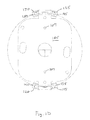
- FIG. 2 is a cross-sectional view of the torsion spring bracket of FIGS. 1A-D installed in a surface cylinder housing in accordance with an example embodiment.
- FIG. 3 is a partial cross-sectional view of an interaction of the torsion spring bracket of FIGS. 1A-D with a light module and trim assembly having torsion springs in accordance with an example embodiment.
- FIG. 4 is a perspective view of an example light emitting diode (LED) light module for use with the torsion spring bracket of FIGS. 1A-D in accordance with an example embodiment.
- LED light emitting diode
- a mounting bracket assembly includes a mounting base and a plurality of arms extending down from the mounting base.
- a first arm of the plurality of arms includes a first pair of inwardly facing hooks coupled to the first arm and defining a first torsion spring receiver area.
- the first arm of the plurality of arms includes a first spring coil ramp disposed along a bottom end of the first arm and extending radially inward from the first arm at a first angle.
- a second arm of the plurality of arms includes a second pair of inwardly facing hooks coupled to the second arm and defining a second torsion spring receiver area.
- the second arm of the plurality of arms includes a second spring coil ramp disposed along a bottom end of the second arm and extending radially inward from the second arm at a second angle.
- a light fixture module in another example embodiment, includes a housing and a mounting bracket assembly coupled to and positioned within the housing.
- the mounting bracket assembly includes a mounting base and a plurality of arms extending down from the mounting base.
- a first arm of the plurality of arms includes a first pair of inwardly facing hooks coupled to the first arm and defining a first torsion spring receiver area.
- the first arm of the plurality of arms also includes a first spring coil ramp disposed along a bottom end of the first arm and extending radially inward from the first arm at a first angle.
- a second arm of the plurality of arms includes a second pair of inwardly facing hooks coupled to the second arm and defining a second torsion spring receiver area.
- the second arm of the plurality of arms also includes a second spring coil ramp disposed along a bottom end of the second arm and extending radially inward from the second arm at a second angle.
- a light fixture in another example embodiment, includes a housing, a mounting bracket assembly coupled to and positioned within the housing, and a light module including a light engine, wherein the light module is coupled to the mounting bracket assembly.
- the mounting bracket assembly includes a mounting base and a plurality of arms extending down from the mounting base.
- a first arm of the plurality of arms includes a first pair of inwardly facing hooks coupled to the first arm and defining a first torsion spring receiver area.
- the first arm of the plurality of arms also includes a first spring coil ramp disposed along a bottom end of the first arm and extending radially inward from the first arm at a first angle.
- the mounting bracket assembly includes a second arm of the plurality of arms including a second pair of inwardly facing hooks coupled to the second arm and defining a second torsion spring receiver area.
- the second arm of the plurality of arms also includes a second spring coil ramp disposed along a bottom end of the second arm and extending radially inward from the second arm at a second angle.
- Example embodiments disclosed herein are directed to a luminaire having a cylinder housing designed to receive an LED light module or for use with an LED light module.
- the cylinder housing (hereinafter referred to as a “surface cylinder housing”) may be a surface-mounted, a wall-mounted, a pendant-mounted, or a cable-mounted housing usable in a corresponding luminaire.
- the example embodiments provide the capability to use torsion spring assemblies to install and remove the LED light module from within the surface cylinder housing that is usable in a corresponding surface-mounted, wall-mounted, pendant-mounted, or cable-mounted luminaire.
- FIGS. 1A-D present various views of a torsion spring bracket assembly 100 in accordance with an example embodiment.
- the example torsion spring bracket assembly 100 includes a mounting base 105 and one or more arms 110 extending away from the mounting base 105 .
- the example base 105 is planar or substantially planar and includes a top surface and opposing bottom surface.
- the top surface includes a pair of mounting posts 107 extending up orthogonally from the top surface of the mounting base 105 .
- each mounting post 107 is threaded and designed to be positioned through a ceiling member of a surface cylinder housing to couple the torsion spring bracket assembly 100 to the surface cylinder housing, as described below.
- the mounting base 105 can also include one or more apertures extending through the surface of the mounting base 105 for removably coupling additional components, such as LED drivers.
- the assembly 100 includes two arms 110 a and 110 b that extend orthogonally or substantially orthogonally down from the base 105 .
- the base 105 can include a pair of tabs 109 that extend out from the base along the same plane and the arms 110 a and 110 b can be attached and extend down from these tabs 109 . In such a case, the tabs 109 are considered part of the base 105 .
- each arm 110 a , 110 b extends angularly out from the bottom side of the base 105 . The angle can be in the range of 0.1-30 degrees off of vertical in this alternative embodiment.
- each arm 110 a , 110 b is disposed on an opposing side of the base 105 .
- the arms 110 a and 110 b extend along parallel planes in certain example embodiments.
- Each arm 110 a , 110 b has a flat or substantially flat planar surface that includes a first end coupled to the base 105 and a distal second end.
- a pair of flange members 115 , 120 can extend out from the first arm 110 a in an area adjacent to the arm's second end and another pair of flange members 125 , 130 can extend out from the second arm 110 b in an area adjacent to that arm's second end.
- each respective pair of flange members 115 , 120 and 125 , 130 are positioned along opposite longitudinal edges of the respective arm 110 a , 110 b .
- each flange member 115 - 130 is coupled to and extends angularly from the respective arm 110 a , 110 b .
- the angle the flange members 115 - 130 are positioned with respect to the respective arm 110 a , 110 b can generally correspond to the radius of curvature of the inner surface of the surface cylinder housing that the assembly 100 is coupled to and can range from 0-45 degrees in certain example embodiments.
- the flange members 115 - 130 are integrally formed with their respective arms 110 a , 110 b.
- Each flange member 115 - 130 can have a first end, a distal second end and a substantially planar surface disposed between the first and second ends.
- the second end of each flange member 115 - 130 is adjacent to the second end of the respective arm 110 .
- a torsion spring receiver hook 135 , 140 , 145 , 150 Positioned along the first end of each flange member 115 - 130 is a torsion spring receiver hook 135 , 140 , 145 , 150 .
- each hook 135 , 140 , 145 , 150 is coupled and extends from the respective arm 110 and eliminates the need for the flange members 115 - 130 .
- Each hook 135 , 140 , 145 , 150 can include a first member 142 extending angularly out from the first end of the respective flange member 115 - 130 and a second member 144 extending angulary or orthogonally from the first member.
- the first member 142 is positioned at an angle of about 45 degrees from vertical with respect to its respective flange member 115 - 130 . In other example embodiments, the angle of the first member 142 ranges from 1-90 degrees from vertical.
- Each pair of hooks 135 , 140 and 145 , 150 face inward toward each other in certain example embodiments.
- An opening is defined by the ends of the second members 144 of each pair of hooks that leads to a torsion spring receiver area that is defined by the arm 110 respective flange members 115 , 120 or 125 , 130 and the inner edges of the respective pairs of hooks 135 , 140 or 145 , 150 .
- FIG. 4 is a perspective view of an example LED light module 301 with torsion springs that can be installed into the torsion spring bracket assembly 100 .
- the LED light module 301 includes a light engine 320 and a trim 315 coupled to the light engine 320 .
- the trim 315 is removably coupled to the light engine 320 .
- Torsion springs 302 can be positioned and coupled to opposing sides of the light engine 320 , either directly or through the use of a bracket (as shown).
- Each example torsion spring 302 includes a spring coil 305 and shafts 310 extending away from the spring coil 305 .
- Each shaft 310 can include a hook-shaped feature 312 at the distal end of the shaft 310 .
- a user can install the light module 301 into the assembly 100 within a surface cylinder housing by squeezing the two ends of respective shafts 310 together and inserting the shafts 310 through the opening defined by the ends of the corresponding second members 144 and inserting the shafts 310 into the torsion spring receiver area.
- the spring coil 305 is twisted tighter, resulting in a force that attempts to cause the ends 312 to retract or move away from one-another while in the torsion spring receiver area.
- the shafts 310 When the shafts 310 contact the inner edges of the hooks 135 , 140 , 145 , 150 , while continuing to retract, it can cause the torsion spring 302 to help lift the light module 301 into the surface cylinder housing and maintain the light module 301 within the surface cylinder housing.
- each arm 110 Positioned near the bottom of the second end of each arm 110 is a spring coil ramp 180 .
- the spring coil ramp 180 , 185 is formed from a portion of the respective arm 110 .
- the spring coil ramp 180 , 185 is a tab-like member coupled to or near the bottom of the second end of the arm 110 .
- Each example spring coil ramp 180 , 185 extends angularly inward from it respective arm 110 .
- spring coil ramp 180 extends angularly inward from arm 110 a and spring coil ramp 185 extends angularly inward from arm 110 b .
- each spring coil ramp 180 , 185 is angled about 10 degrees from the surface of its respective arm 110 .
- each spring coil ramp 180 , 185 is configured such that the inner surface of the end of each respective ramp 180 , 185 extends to a point radially equal to or a little less than the lip portion 220 extending from the wall 215 of the can housing, as best shown in FIG. 3 .
- FIG. 2 is a cross-sectional view of the torsion spring bracket assembly 100 of FIGS. 1A-D installed in a surface cylinder housing 200 in accordance with an example embodiment.
- the example torsion spring bracket assembly 100 can be installed in a surface cylinder housing, such as the surface cylinder housing 200 of FIG. 200 .
- the surface cylinder housing 200 can have a substantially cylindrical shape and can include a top end 205 that includes a mounting surface 210 and an outer wall 215 generally extending down from the top end 205 .
- a lip portion 220 can extend radially inward from the outer wall 215 .
- the mounting posts 107 of the assembly 100 can extend through openings in the mounting surface 210 to couple the mounting base 105 to the mounting surface 210 .
- an LED driver 240 or other electrical components can be coupled to the bottom side of the mounting base 105 .
- Each arm 110 can be positioned generally along the outer wall 215 and extend down towards the lip portion 220 and the bottom of the surface cylinder housing 220 .
- the LED driver 240 is coupled to the torsion spring bracket assembly 100 , where the torsion spring bracket assembly 100 may provide an electrical ground path for electricity related to the LED driver 240 .
- the torsion spring bracket assembly 100 may be made from a metal (e.g., aluminum) and, as a conductor, may be used to provide an electrical ground path for the LED driver 240 and/or other electrical components that are coupled to it.
- the torsion spring bracket assembly 100 may serve as a heat conduit to transfer heat from, for example, the LED driver 240 to the surface cylinder housing 200 .
- the torsion spring bracket assembly 100 may provide a heat transfer path between the LED driver 240 and the surface cylinder housing 200 .
- the torsion spring bracket assembly 100 may be made from a metal such as aluminum for efficient heat transfer and may operate as part of a luminaire's heat sink.
- FIG. 3 is a partial cross-sectional view showing the interaction of the torsion spring coil from a light module 301 and one of the spring coil ramps 185 , as the light module 301 is being removed from the can housing.
- the light module 301 including the light engine 320 and trim 315 , are moved downward towards the opening in the can housing.
- the spring coil 305 moves down and along an area adjacent to the arm 110 and as it approaches the bottom of the arm 110 it can contact the spring coil ramp 185 if the spring coil 305 is too close to the wall 215 of the can housing.
- Contacting the ramp 185 forces the spring coil 305 back towards the center of the opening and away from the lip 220 of the housing, thereby reducing the possibility the coil 305 catches on the lip 220 during removal of the light module 301 .
- the spring coil ramp 180 , 185 can be positioned at an angle anywhere between 1-60 degrees. In certain exemplary embodiments, the bottom edge of the spring coil ramp 180 , 185 is at substantially the same vertical position as the second end of the flange members 115 - 130 .
Abstract
Description
Claims (20)
Priority Applications (1)
| Application Number | Priority Date | Filing Date | Title |
|---|---|---|---|
| US13/887,108 US9341349B1 (en) | 2012-05-03 | 2013-05-03 | Systems, methods, and devices for providing a torsion spring bracket assembly for use in cylindrical luminaire housings |
Applications Claiming Priority (2)
| Application Number | Priority Date | Filing Date | Title |
|---|---|---|---|
| US201261642014P | 2012-05-03 | 2012-05-03 | |
| US13/887,108 US9341349B1 (en) | 2012-05-03 | 2013-05-03 | Systems, methods, and devices for providing a torsion spring bracket assembly for use in cylindrical luminaire housings |
Publications (1)
| Publication Number | Publication Date |
|---|---|
| US9341349B1 true US9341349B1 (en) | 2016-05-17 |
Family
ID=55920044
Family Applications (1)
| Application Number | Title | Priority Date | Filing Date |
|---|---|---|---|
| US13/887,108 Active 2033-06-20 US9341349B1 (en) | 2012-05-03 | 2013-05-03 | Systems, methods, and devices for providing a torsion spring bracket assembly for use in cylindrical luminaire housings |
Country Status (1)
| Country | Link |
|---|---|
| US (1) | US9341349B1 (en) |
Cited By (6)
| Publication number | Priority date | Publication date | Assignee | Title |
|---|---|---|---|---|
| US9803838B1 (en) * | 2015-10-20 | 2017-10-31 | Cooper Technologies Company | Support brackets for lamp sockets |
| USD886569S1 (en) | 2018-12-31 | 2020-06-09 | Luminii | Mounting bracket |
| US10704770B2 (en) * | 2018-09-11 | 2020-07-07 | CP IP Holdings Limited | Lighting arrangement |
| USD899898S1 (en) | 2018-12-31 | 2020-10-27 | Luminii | Mounting bracket |
| US10816173B2 (en) | 2018-12-31 | 2020-10-27 | Luminii | Mounting brackets |
| US10907807B1 (en) * | 2019-07-11 | 2021-02-02 | Dong Guan Jia Sheng Lighting Technology Co., Ltd. China | Ceiling light fixture assembled easily and quickly |
Citations (16)
| Publication number | Priority date | Publication date | Assignee | Title |
|---|---|---|---|---|
| US6364511B1 (en) * | 2000-03-31 | 2002-04-02 | Amp Plus, Inc. | Universal adapter bracket and ornamental trim assembly using same for in-ceiling recessed light fixtures |
| US20020167257A1 (en) * | 2001-05-11 | 2002-11-14 | Shen Wei Hong | Clamping structure assembly of projection lamp |
| US20030160141A1 (en) * | 2002-02-27 | 2003-08-28 | Satoru Yamanashi | Structure for mounting heavy article to carrier body |
| US7059745B2 (en) * | 2002-02-07 | 2006-06-13 | Musco Corporation | Lighting fixture with quick-disconnect light source mount |
| US20070223233A1 (en) * | 2006-03-23 | 2007-09-27 | Chin-Sheng Teng | Lamp holder frame |
| US20090039799A1 (en) * | 2007-08-08 | 2009-02-12 | Newman Jr Robert C | Ballasted lamp socket for a compact fluorescent lamp |
| US20090244911A1 (en) * | 2008-03-27 | 2009-10-01 | Leviton Manufacturing Company, Inc. | rotatable lampholder with securing elements |
| US20090296403A1 (en) * | 2008-05-28 | 2009-12-03 | Fu Zhun Precision Industry (Shen Zhen) Co., Ltd. | Led lamp |
| US7628504B2 (en) * | 2005-07-11 | 2009-12-08 | Glickman Mark F | Light fixture retrofitting apparatus and method |
| US20100002444A1 (en) * | 2006-09-20 | 2010-01-07 | Osram Gesellschaft Mit Beschrankter Haftung | Bulb-shaped led lamp and compact led lamp |
| US20110063849A1 (en) * | 2009-08-12 | 2011-03-17 | Journée Lighting, Inc. | Led light module for use in a lighting assembly |
| US20110134650A1 (en) * | 2009-12-08 | 2011-06-09 | Cooper Technologies Company | Adaptor Band |
| US20110149552A1 (en) * | 2008-09-01 | 2011-06-23 | Suavi Atalay | Oven lamp holder with bayonet lock |
| US20120300484A1 (en) * | 2011-05-24 | 2012-11-29 | Koito Manufacturing Co., Ltd. | Vehicle headlamp and projection lens mounting method |
| US20130039037A1 (en) * | 2011-08-09 | 2013-02-14 | Custom Molded Products, Inc. | Pool light adapter ring |
| US20130271979A1 (en) * | 2012-04-17 | 2013-10-17 | Dennis Pearson | Scalable LED Sconce Light |
-
2013
- 2013-05-03 US US13/887,108 patent/US9341349B1/en active Active
Patent Citations (16)
| Publication number | Priority date | Publication date | Assignee | Title |
|---|---|---|---|---|
| US6364511B1 (en) * | 2000-03-31 | 2002-04-02 | Amp Plus, Inc. | Universal adapter bracket and ornamental trim assembly using same for in-ceiling recessed light fixtures |
| US20020167257A1 (en) * | 2001-05-11 | 2002-11-14 | Shen Wei Hong | Clamping structure assembly of projection lamp |
| US7059745B2 (en) * | 2002-02-07 | 2006-06-13 | Musco Corporation | Lighting fixture with quick-disconnect light source mount |
| US20030160141A1 (en) * | 2002-02-27 | 2003-08-28 | Satoru Yamanashi | Structure for mounting heavy article to carrier body |
| US7628504B2 (en) * | 2005-07-11 | 2009-12-08 | Glickman Mark F | Light fixture retrofitting apparatus and method |
| US20070223233A1 (en) * | 2006-03-23 | 2007-09-27 | Chin-Sheng Teng | Lamp holder frame |
| US20100002444A1 (en) * | 2006-09-20 | 2010-01-07 | Osram Gesellschaft Mit Beschrankter Haftung | Bulb-shaped led lamp and compact led lamp |
| US20090039799A1 (en) * | 2007-08-08 | 2009-02-12 | Newman Jr Robert C | Ballasted lamp socket for a compact fluorescent lamp |
| US20090244911A1 (en) * | 2008-03-27 | 2009-10-01 | Leviton Manufacturing Company, Inc. | rotatable lampholder with securing elements |
| US20090296403A1 (en) * | 2008-05-28 | 2009-12-03 | Fu Zhun Precision Industry (Shen Zhen) Co., Ltd. | Led lamp |
| US20110149552A1 (en) * | 2008-09-01 | 2011-06-23 | Suavi Atalay | Oven lamp holder with bayonet lock |
| US20110063849A1 (en) * | 2009-08-12 | 2011-03-17 | Journée Lighting, Inc. | Led light module for use in a lighting assembly |
| US20110134650A1 (en) * | 2009-12-08 | 2011-06-09 | Cooper Technologies Company | Adaptor Band |
| US20120300484A1 (en) * | 2011-05-24 | 2012-11-29 | Koito Manufacturing Co., Ltd. | Vehicle headlamp and projection lens mounting method |
| US20130039037A1 (en) * | 2011-08-09 | 2013-02-14 | Custom Molded Products, Inc. | Pool light adapter ring |
| US20130271979A1 (en) * | 2012-04-17 | 2013-10-17 | Dennis Pearson | Scalable LED Sconce Light |
Cited By (6)
| Publication number | Priority date | Publication date | Assignee | Title |
|---|---|---|---|---|
| US9803838B1 (en) * | 2015-10-20 | 2017-10-31 | Cooper Technologies Company | Support brackets for lamp sockets |
| US10704770B2 (en) * | 2018-09-11 | 2020-07-07 | CP IP Holdings Limited | Lighting arrangement |
| USD886569S1 (en) | 2018-12-31 | 2020-06-09 | Luminii | Mounting bracket |
| USD899898S1 (en) | 2018-12-31 | 2020-10-27 | Luminii | Mounting bracket |
| US10816173B2 (en) | 2018-12-31 | 2020-10-27 | Luminii | Mounting brackets |
| US10907807B1 (en) * | 2019-07-11 | 2021-02-02 | Dong Guan Jia Sheng Lighting Technology Co., Ltd. China | Ceiling light fixture assembled easily and quickly |
Similar Documents
| Publication | Publication Date | Title |
|---|---|---|
| US9341349B1 (en) | Systems, methods, and devices for providing a torsion spring bracket assembly for use in cylindrical luminaire housings | |
| US9702533B1 (en) | Method and system for luminaire mounting | |
| US10458628B2 (en) | Led luminaire with adaptable installation kit | |
| US7148420B1 (en) | Electrical ceiling box for fixture support | |
| US9146027B2 (en) | Device for holding a source of LED light | |
| US9739455B2 (en) | LED light engines | |
| US20120020094A1 (en) | Ceiling lamp | |
| US20060152920A1 (en) | Adapter device for mounting a ceiling electrical light fixture | |
| US8517325B2 (en) | Adaptor band | |
| US10520169B2 (en) | Snap in retrofit panel | |
| US10422512B2 (en) | Bay luminaire with yoke assembly | |
| US20180358746A1 (en) | Industrial connector and connecting structure | |
| US20170299155A1 (en) | Device for connecting a light fixture to a shade for vanity lighting and pendant lighting | |
| JP2021166181A (en) | Plastic down light fixture having mutual locking attachment feature | |
| JP2010073391A (en) | Reflector for lighting fixture of straight-tube fluorescent lamp | |
| CN107842720B (en) | Strip-shaped lamp and assembling method and disassembling method thereof | |
| US7401950B2 (en) | Assembly for vertically positioning a lamp-shade | |
| CN105698064A (en) | Improvement part set and improvement method of embedded lamp | |
| US7287883B1 (en) | Yielding hanger for stem mounting fluorescent highbays | |
| US20190137058A1 (en) | Panel light apparatus | |
| US10072806B1 (en) | Luminaire downlight | |
| US20140078731A1 (en) | Led socket adapter assembly | |
| JP2015125976A (en) | Lighting device fixture | |
| TWM592938U (en) | Lamp device and lamp carrier board | |
| US20210176546A1 (en) | Voice-enabled device recessed installation |
Legal Events
| Date | Code | Title | Description |
|---|---|---|---|
| AS | Assignment |
Owner name: COOPER TECHNOLOGIES COMPANY, TEXAS Free format text: ASSIGNMENT OF ASSIGNORS INTEREST;ASSIGNOR:MOORE, MICHAEL DARRILL;REEL/FRAME:037556/0971 Effective date: 20120507 |
|
| STCF | Information on status: patent grant |
Free format text: PATENTED CASE |
|
| AS | Assignment |
Owner name: EATON INTELLIGENT POWER LIMITED, IRELAND Free format text: ASSIGNMENT OF ASSIGNORS INTEREST;ASSIGNOR:COOPER TECHNOLOGIES COMPANY;REEL/FRAME:048207/0819 Effective date: 20171231 |
|
| AS | Assignment |
Owner name: EATON INTELLIGENT POWER LIMITED, IRELAND Free format text: CORRECTIVE ASSIGNMENT TO CORRECT THE COVER SHEET TO REMOVE APPLICATION NO. 15567271 PREVIOUSLY RECORDED ON REEL 048207 FRAME 0819. ASSIGNOR(S) HEREBY CONFIRMS THE ASSIGNMENT;ASSIGNOR:COOPER TECHNOLOGIES COMPANY;REEL/FRAME:048655/0114 Effective date: 20171231 |
|
| MAFP | Maintenance fee payment |
Free format text: PAYMENT OF MAINTENANCE FEE, 4TH YEAR, LARGE ENTITY (ORIGINAL EVENT CODE: M1551); ENTITY STATUS OF PATENT OWNER: LARGE ENTITY Year of fee payment: 4 |
|
| AS | Assignment |
Owner name: SIGNIFY HOLDING B.V., NETHERLANDS Free format text: ASSIGNMENT OF ASSIGNORS INTEREST;ASSIGNOR:EATON INTELLIGENT POWER LIMITED;REEL/FRAME:052681/0475 Effective date: 20200302 |
|
| AS | Assignment |
Owner name: SIGNIFY HOLDING B.V., NETHERLANDS Free format text: CORRECTIVE ASSIGNMENT TO CORRECT THE APPLICATION NUMBERS 12183490, 12183499, 12494944, 12961315, 13528561, 13600790, 13826197, 14605880, 15186648, RECORDED IN ERROR PREVIOUSLY RECORDED ON REEL 052681 FRAME 0475. ASSIGNOR(S) HEREBY CONFIRMS THE ASSIGNMENT;ASSIGNOR:EATON INTELLIGENT POWER LIMITED;REEL/FRAME:055965/0721 Effective date: 20200302 |
|
| FEPP | Fee payment procedure |
Free format text: MAINTENANCE FEE REMINDER MAILED (ORIGINAL EVENT CODE: REM.); ENTITY STATUS OF PATENT OWNER: LARGE ENTITY |