US9313007B2 - Wireless apparatus and training signal transmission method - Google Patents
Wireless apparatus and training signal transmission method Download PDFInfo
- Publication number
- US9313007B2 US9313007B2 US14/372,643 US201314372643A US9313007B2 US 9313007 B2 US9313007 B2 US 9313007B2 US 201314372643 A US201314372643 A US 201314372643A US 9313007 B2 US9313007 B2 US 9313007B2
- Authority
- US
- United States
- Prior art keywords
- transmission
- channel information
- channel
- iterative
- frequency channels
- Prior art date
- Legal status (The legal status is an assumption and is not a legal conclusion. Google has not performed a legal analysis and makes no representation as to the accuracy of the status listed.)
- Active, expires
Links
Images


Classifications
-
- H—ELECTRICITY
- H04—ELECTRIC COMMUNICATION TECHNIQUE
- H04L—TRANSMISSION OF DIGITAL INFORMATION, e.g. TELEGRAPHIC COMMUNICATION
- H04L5/00—Arrangements affording multiple use of the transmission path
- H04L5/003—Arrangements for allocating sub-channels of the transmission path
- H04L5/0053—Allocation of signaling, i.e. of overhead other than pilot signals
-
- H—ELECTRICITY
- H04—ELECTRIC COMMUNICATION TECHNIQUE
- H04B—TRANSMISSION
- H04B7/00—Radio transmission systems, i.e. using radiation field
- H04B7/02—Diversity systems; Multi-antenna system, i.e. transmission or reception using multiple antennas
- H04B7/04—Diversity systems; Multi-antenna system, i.e. transmission or reception using multiple antennas using two or more spaced independent antennas
- H04B7/0413—MIMO systems
- H04B7/0456—Selection of precoding matrices or codebooks, e.g. using matrices antenna weighting
-
- H—ELECTRICITY
- H04—ELECTRIC COMMUNICATION TECHNIQUE
- H04B—TRANSMISSION
- H04B7/00—Radio transmission systems, i.e. using radiation field
- H04B7/02—Diversity systems; Multi-antenna system, i.e. transmission or reception using multiple antennas
- H04B7/04—Diversity systems; Multi-antenna system, i.e. transmission or reception using multiple antennas using two or more spaced independent antennas
- H04B7/06—Diversity systems; Multi-antenna system, i.e. transmission or reception using multiple antennas using two or more spaced independent antennas at the transmitting station
- H04B7/0613—Diversity systems; Multi-antenna system, i.e. transmission or reception using multiple antennas using two or more spaced independent antennas at the transmitting station using simultaneous transmission
- H04B7/0615—Diversity systems; Multi-antenna system, i.e. transmission or reception using multiple antennas using two or more spaced independent antennas at the transmitting station using simultaneous transmission of weighted versions of same signal
- H04B7/0617—Diversity systems; Multi-antenna system, i.e. transmission or reception using multiple antennas using two or more spaced independent antennas at the transmitting station using simultaneous transmission of weighted versions of same signal for beam forming
-
- H—ELECTRICITY
- H04—ELECTRIC COMMUNICATION TECHNIQUE
- H04B—TRANSMISSION
- H04B7/00—Radio transmission systems, i.e. using radiation field
- H04B7/02—Diversity systems; Multi-antenna system, i.e. transmission or reception using multiple antennas
- H04B7/04—Diversity systems; Multi-antenna system, i.e. transmission or reception using multiple antennas using two or more spaced independent antennas
- H04B7/06—Diversity systems; Multi-antenna system, i.e. transmission or reception using multiple antennas using two or more spaced independent antennas at the transmitting station
- H04B7/0613—Diversity systems; Multi-antenna system, i.e. transmission or reception using multiple antennas using two or more spaced independent antennas at the transmitting station using simultaneous transmission
- H04B7/068—Diversity systems; Multi-antenna system, i.e. transmission or reception using multiple antennas using two or more spaced independent antennas at the transmitting station using simultaneous transmission using space frequency diversity
-
- H—ELECTRICITY
- H04—ELECTRIC COMMUNICATION TECHNIQUE
- H04B—TRANSMISSION
- H04B7/00—Radio transmission systems, i.e. using radiation field
- H04B7/02—Diversity systems; Multi-antenna system, i.e. transmission or reception using multiple antennas
- H04B7/04—Diversity systems; Multi-antenna system, i.e. transmission or reception using multiple antennas using two or more spaced independent antennas
- H04B7/06—Diversity systems; Multi-antenna system, i.e. transmission or reception using multiple antennas using two or more spaced independent antennas at the transmitting station
- H04B7/0613—Diversity systems; Multi-antenna system, i.e. transmission or reception using multiple antennas using two or more spaced independent antennas at the transmitting station using simultaneous transmission
- H04B7/0684—Diversity systems; Multi-antenna system, i.e. transmission or reception using multiple antennas using two or more spaced independent antennas at the transmitting station using simultaneous transmission using different training sequences per antenna
-
- H—ELECTRICITY
- H04—ELECTRIC COMMUNICATION TECHNIQUE
- H04J—MULTIPLEX COMMUNICATION
- H04J11/00—Orthogonal multiplex systems, e.g. using WALSH codes
- H04J11/0023—Interference mitigation or co-ordination
- H04J11/0026—Interference mitigation or co-ordination of multi-user interference
- H04J11/003—Interference mitigation or co-ordination of multi-user interference at the transmitter
-
- H—ELECTRICITY
- H04—ELECTRIC COMMUNICATION TECHNIQUE
- H04W—WIRELESS COMMUNICATION NETWORKS
- H04W72/00—Local resource management
- H04W72/04—Wireless resource allocation
- H04W72/044—Wireless resource allocation based on the type of the allocated resource
- H04W72/0453—Resources in frequency domain, e.g. a carrier in FDMA
-
- H—ELECTRICITY
- H04—ELECTRIC COMMUNICATION TECHNIQUE
- H04L—TRANSMISSION OF DIGITAL INFORMATION, e.g. TELEGRAPHIC COMMUNICATION
- H04L25/00—Baseband systems
- H04L25/02—Details ; arrangements for supplying electrical power along data transmission lines
- H04L25/0202—Channel estimation
- H04L25/0204—Channel estimation of multiple channels
-
- H—ELECTRICITY
- H04—ELECTRIC COMMUNICATION TECHNIQUE
- H04L—TRANSMISSION OF DIGITAL INFORMATION, e.g. TELEGRAPHIC COMMUNICATION
- H04L25/00—Baseband systems
- H04L25/02—Details ; arrangements for supplying electrical power along data transmission lines
- H04L25/0202—Channel estimation
- H04L25/0224—Channel estimation using sounding signals
- H04L25/0226—Channel estimation using sounding signals sounding signals per se
-
- H—ELECTRICITY
- H04—ELECTRIC COMMUNICATION TECHNIQUE
- H04L—TRANSMISSION OF DIGITAL INFORMATION, e.g. TELEGRAPHIC COMMUNICATION
- H04L25/00—Baseband systems
- H04L25/02—Details ; arrangements for supplying electrical power along data transmission lines
- H04L25/0202—Channel estimation
- H04L25/0224—Channel estimation using sounding signals
- H04L25/0228—Channel estimation using sounding signals with direct estimation from sounding signals
- H04L25/023—Channel estimation using sounding signals with direct estimation from sounding signals with extension to other symbols
- H04L25/0232—Channel estimation using sounding signals with direct estimation from sounding signals with extension to other symbols by interpolation between sounding signals
-
- H—ELECTRICITY
- H04—ELECTRIC COMMUNICATION TECHNIQUE
- H04L—TRANSMISSION OF DIGITAL INFORMATION, e.g. TELEGRAPHIC COMMUNICATION
- H04L5/00—Arrangements affording multiple use of the transmission path
- H04L5/0001—Arrangements for dividing the transmission path
- H04L5/0014—Three-dimensional division
- H04L5/0023—Time-frequency-space
-
- H—ELECTRICITY
- H04—ELECTRIC COMMUNICATION TECHNIQUE
- H04L—TRANSMISSION OF DIGITAL INFORMATION, e.g. TELEGRAPHIC COMMUNICATION
- H04L5/00—Arrangements affording multiple use of the transmission path
- H04L5/003—Arrangements for allocating sub-channels of the transmission path
- H04L5/0048—Allocation of pilot signals, i.e. of signals known to the receiver
-
- H—ELECTRICITY
- H04—ELECTRIC COMMUNICATION TECHNIQUE
- H04W—WIRELESS COMMUNICATION NETWORKS
- H04W88/00—Devices specially adapted for wireless communication networks, e.g. terminals, base stations or access point devices
- H04W88/08—Access point devices
Definitions
- the present invention relates to a wireless apparatus which estimates channel information between a plurality of transmission ports and receive antennas of communication partners in communication using an orthogonal frequency-division multiplexing scheme, and a training signal transmission method.
- MU-MIMO multiuser MIMO
- the MU-MIMO communication has a potential to increase the throughput in the physical layer by a factor equal to the number of transmit antennas, but a transmitting apparatus requires channel information for stations in order to obtain a transmission diversity effect using many transmit antennas.
- overhead is increased due to a signal for estimating the channel information and feedback information.
- FIG. 10 is a sequence diagram describing an operation of acquiring channel information of OFDM communication in accordance with the conventional art.
- FIG. 10 illustrates an example in which an access point AP acquires channel information for K stations (STAs) STA-1 to STA-K.
- K is an integer which is greater than or equal to 1.
- reference sign 1 represents an announce signal (null data packet announce (NDPA)) indicating that a signal for channel estimation is transmitted
- reference sign 2 represents a pilot signal for estimation (null data packet (NDP))
- reference signs 3 - 1 to 3 -K represent feedback signals (channel state information feedback (CSIFB)) of channel information
- reference signs 4 - 2 to 4 -K represent polling signals (Polling) instructing a specific communication partner to transmit a response signal.
- NDPA announce signal
- NDP pilot signal for estimation
- reference signs 3 - 1 to 3 -K represent feedback signals (channel state information feedback (CSIFB)) of channel information
- reference signs 4 - 2 to 4 -K represent polling signals (Polling) instructing a specific communication partner to transmit a response signal.
- CSIFB channel state information feedback
- the pilot signal 2 includes a first pilot symbol 2 - 1 - 1 , a last pilot symbol 2 - 1 - 2 , and N very high throughput-long training frames (VHT-LTFs) 2 - 2 - 1 to 2 - 2 -N for enabling channel estimation corresponding to N transmit antennas.
- VHT-LTFs very high throughput-long training frames
- a signal S k of a k th frequency channel of the VHT-LTFs 2 - 2 - 1 to 2 - 2 -N can be determined as, for example, in Equations (19-11), (19-12), (19-23), and (19-24) disclosed in Non-Patent Document 2.
- FIG. 11 is a block diagram illustrating a configuration of an access point (AP) 10 which acquires channel information of a wireless section of an OFDM signal in accordance with the conventional art.
- Reference sign 10 - 2 represents a long training frame generating circuit
- reference sign 10 - 3 represents a wireless signal transmitting/receiving circuit
- reference signs 10 - 4 - 1 to 10 - 4 -N represent transmit/receive antennas
- reference sign 10 - 5 represents a received signal demodulating circuit
- reference sign 10 - 6 represents a feedback information extracting circuit
- reference sign 10 - 7 represents a channel information acquiring circuit.
- an announce signal (NDPA) 1 and a pilot signal (NDP) 2 in FIG. 10 are generated in the long training frame generation circuit 10 - 2 , and conversion into analog signals, conversion into carrier frequencies, amplification, and so on are performed by the wireless signal transmitting/receiving circuit 10 - 3 , and transmission is performed via the transmit/receive antennas 10 - 4 - 1 to 10 - 4 -N.
- the access point (AP) 10 receives the signals via at least one of the transmit/receive antennas 10 - 4 - 1 to 10 - 4 -N by using the wireless signal transmitting/receiving circuit 10 - 3 and outputs digital signals to the received signal demodulating circuit 10 - 5 .
- the received signal demodulating circuit 10 - 5 establishes synchronization with the received signals, and obtains information acquired from any one of the stations STA-1 to STA-K by, for example, using channel information.
- the feedback information extracting circuit 10 - 6 extracts a feedback portion of the channel information by as feedback signal CSIFB of the channel information from the obtained demodulated bits, and the channel information acquiring circuit 10 - 7 acquires the channel information in each frequency channel.
- the fed-back channel information may be propagation channel information for a time domain, or it may be channel information in each frequency channel of OFDM, or information similar to the channel information, e.g., basis vectors obtained by applying a Gram-Schmidt orthogonalization method to the channel information, a right singular matrix of a channel information matrix, or the like can be used.
- the feedback of the channel information may be compressed by representing a V matrix by angles ⁇ and ⁇ or it may be obtained by acquiring part of information of frequency channels of OFDM (e.g., see Non-Patent Document 3).
- the channel information acquiring circuit 10 - 7 estimates the original channel information by decompressing or interpolating the feedback information and stores the original channel information.
- the present invention has been made in consideration of such circumstances, and an object thereof is to provide a wireless apparatus and a training signal transmission method capable of reducing the number of OFDM symbols for channel estimation, reducing overhead due to a pilot signal and a feedback signal, and improving the throughput.
- the present invention is a wireless apparatus which estimates channel information between a plurality of transmission ports and receive antennas of a communication partner in communication based on an orthogonal frequency-division multiplexing scheme
- the wireless apparatus includes: an iterative coefficient setting unit which sets an iterative coefficient representing the number of transmission ports which share a plurality of frequency channels of training signals for estimating the channel information for the plurality of transmission ports; a training signal generating unit which allocates frequency channels to each transmission port so as to satisfy the iterative coefficient set by the iterative coefficient setting unit and generates L (L is a positive integer) training signals based on the allocated frequency channels; a wireless transmitting unit which outputs the training signals generated by the training signal generating unit to transmit antennas; a channel information acquiring unit which acquires channel information estimated from the training signals transmitted by the transmit antennas from the communication partner for the frequency channels allocated to each transmission port; and a channel information interpolating unit which interpolates channel information of a remaining frequency channel other than the frequency channels
- the iterative coefficient setting unit may set iterative coefficients as ⁇ 1 to ⁇ M for M (M is a positive integer) transmission ports and set the iterative coefficients ⁇ 1 to ⁇ M so that a sum of reciprocals of the iterative coefficients ⁇ 1 to ⁇ M becomes the integer L.
- the training signal generating unit may allocate the frequency channels to each transmission port so as to satisfy the iterative coefficient, multiply signals corresponding to the same frequency channel of the L training signals by an L ⁇ L transform matrix, and allocate obtained L signals to the L training signals, and the wireless transmitting unit may output the training signals generated by the training signal generating unit to the transmit antennas.
- the iterative coefficient setting unit may set, for each transmission port, an iterative coefficient set for a transmission port in which a vector corresponding to a signal space estimated using a set matrix of channel matrices for the receive antennas of the communication partner previously estimated serves as a transmission weight to a value less than an iterative coefficient corresponding to a null space which is orthogonal to the vector corresponding to the signal space.
- the present invention is a training signal transmission method of a wireless apparatus which estimates channel information between a plurality of transmission ports and receive antennas of a communication partner in communication based on an orthogonal frequency-division multiplexing scheme
- the training signal transmission method includes: an iterative coefficient setting step of setting an iterative coefficient representing the number of transmission ports which share a plurality of frequency channels of training signals for estimating the channel information for the plurality of transmission ports; a training signal generating step of allocating frequency channels to each transmission port so as to satisfy the iterative coefficient set in the iterative coefficient setting step and generating L (L is a positive integer) training signals based on the allocated frequency channels; a wireless transmitting step of outputting the training signals generated in the training signal generating step to transmit antennas; a channel information acquiring step of acquiring channel information estimated from the training signals transmitted by the transmit antennas from the communication partner for the frequency channels allocated to each transmission port; and a channel information interpolating step of interpolating channel information of a remaining frequency channel other than the frequency
- the number of OFDM symbols for channel estimation can be set to be less than the number of antennas or the number of transmission beams for which channel information is to be estimated, overhead for the channel estimation can be reduced, and the throughput can be improved.
- FIG. 1 is a block diagram illustrating a configuration of an access point (AP: wireless apparatus) 10 which acquires channel information of a wireless section of an OFDM signal in accordance with a first embodiment of the present invention.
- AP access point
- FIG. 2A is a conceptual diagram illustrating a configuration of a pilot signal NDP in the first embodiment of the present invention.
- FIG. 2B is a conceptual diagram illustrating a configuration of long training frames for channel estimation in the first embodiment of the present invention.
- FIG. 3 is a conceptual diagram illustrating a configuration of long training frames for channel estimation LTF (an example in which an independent value is set as ⁇ for each transmission port) in the first embodiment of the present invention.
- FIG. 4 is a conceptual diagram illustrating a configuration of long training frames for channel estimation (part 1) in a second embodiment of the present invention.
- FIG. 5 is a conceptual diagram illustrating a configuration of long training frames for channel estimation (part 2) in the second embodiment of the present invention.
- FIG. 6 is a conceptual diagram illustrating a correspondence relationship between ranges of a correlation value ⁇ and fixed values ⁇ in the first and second embodiments of the present invention.
- FIG. 7 is a conceptual diagram illustrating a configuration of long training frames for channel estimation (part 3) in the second embodiment of the present invention.
- FIG. 8 is a flowchart describing an operation of acquiring channel information between transmit antennas and communication partners in the first and second embodiments of the present invention.
- FIG. 9 is a flowchart describing an operation of acquiring channel information between transmission beams and communication partners in the first and second embodiments of the present invention.
- FIG. 10 is a frame sequence diagram illustrating an operation of multiuser MIMO communication in accordance with the conventional art.
- FIG. 11 is a block diagram illustrating a configuration of a wireless apparatus which performs transmission based on the multiuser MIMO in accordance with the conventional art.
- FIG. 1 is a block diagram illustrating a configuration of an access point (AP: wireless apparatus) 10 which acquires channel information of a wireless section of an OFDM signal in accordance with the present first embodiment.
- AP access point
- an iterative coefficient setting circuit 10 - 8 determines an iterative coefficient for each transmit antenna or each transmission port which is a transmission beam, the number of long training frames (LTFs) L which are OFDM symbols to be used for channel estimation, the correspondence between transmission ports and each LTF, and allocation of frequency channels.
- LTFs long training frames
- the iterative coefficient is ⁇ which will be described later.
- a frequency channel corresponds to a subcarrier in OFDM transmission.
- a pilot signal NDP illustrated in FIG. 10 all frequency channels are allocated to each transmit antenna and N VHT-LTFs 2 - 2 - 1 to 2 - 2 -N are necessary to acquire channel information for all transmit antennas. That is, in the conventional art, one transmission port occupies all subcarriers of one LTF, and thus channel information is estimated using N LTFs when there are N transmission ports.
- not all frequency channels are allocated to each transmission port and a channel to be estimated is limited, e.g., every two channels or every three channels.
- the number of frequency channels for which a signal for channel estimation of a transmission port of interest is inserted is represented as the iterative coefficient ⁇ , and iterative coefficients are determined as ⁇ 1 to ⁇ M for M transmission ports for which estimation is to be performed.
- 1 ⁇ M ⁇ N is established.
- the present embodiment is characterized in that, rather than each transmission port transmitting one training signal using all subcarriers of the training signal, an iterative coefficient is set and one training signal is shared by a plurality of transmission ports.
- the iterative coefficient ⁇ 1 and a training signal is transmitted using all subcarriers.
- a plurality of transmission ports share one training signal ( ⁇ >1), thereby reducing the necessary number of training signals and improving transmission efficiency.
- channel information of a subcarrier to be omitted by sharing one training signal with other transmission ports, but it is possible to interpolate the channel information of the subcarrier to be omitted with a method using channel information estimated for an adjacent subcarrier or a method using an average of channel information estimated for a plurality of adjacent subcarriers.
- FIGS. 2A and 2B are conceptual diagrams illustrating a configuration of a pilot signal NDP and a configuration of an LTF for channel estimation in the present first embodiment.
- the number of frequency channels in which data or control signals is transmitted is assumed to be 16.
- FIGS. 2A and 2B illustrates, when the access point (AP) 10 in which the number of transmit antennas is 8 transmits a pilot signal NDP for performing channel estimation in each station, pilot symbols 20 - 1 - 1 and 20 - 1 - 2 for channel estimation and long training frames P-LTFs (proposed LTFs) 20 - 2 - 1 to 20 - 2 -L included therein.
- a long training frame generating circuit 10 - 2 allocates transmission ports to LTFs so as to satisfy the determined iterative coefficients.
- the number L of LTFs can be represented by the following Equation (1).
- the bottomless square brackets represent a ceiling function
- a inserted between the bottomless square brackets is an integer obtained by rounding up the decimal places of A. Because it is possible to acquire channel information more efficiently if an arithmetic result of a sum within the function of right-side in Equation (1) is a positive integer L, the iterative coefficient setting circuit 10 - 8 can also set ⁇ 1 to ⁇ M so as to satisfy the following Equation (2).
- L is a positive integer also in the above Equation (2).
- Txi represents an i th transmission port, which indicates an i th transmit antenna or an i th transmission beam. Because the allocation coefficient of each transmission port is 2, channel information corresponding to 2 L transmission ports is obtained from L P-LTFs. Because channel information for one of two frequency channels is estimated, information of a frequency channel that is not estimated can be interpolated using channel information obtained for frequency channels of near frequencies. Because channel information in each frequency channel has a high correlation with channel information of adjacent frequency channels, it is possible to use interpolation, extrapolation, or the like using the correlation. When a larger value is set as ⁇ , the number of P-LTFs to be transmitted can be further reduced and a feedback amount of the channel information can also be further reduced.
- FIG. 3 is a conceptual diagram illustrating a configuration of long training frames for channel estimation (an example in which an independent value is set asp for each transmission port) in the present first embodiment.
- a sum of reciprocals of the iterative coefficients is a positive integer, all frequency channels are used as channel estimation signals.
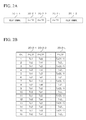
- FIG. 3 illustrates an example in which the value of ⁇ differs depending on each transmission port. Describing in sequence, transmission ports #1 and #2 share one P-LTF 20 - 2 - 1 , transmission ports #3 and #4 share one P-LTF 20 - 2 - 2 , transmission ports #5, #6, and #7 share one P-LTF 20 - 2 - 3 , and transmission ports #8, #9, #10, and #11 share one P-LTF 20 - 2 - 4 . In this case, there is an advantage in that the necessary number of LTFs which is 11 conventionally can be reduced to 4.
- ⁇ j can be set to be smaller when a transmission port has a higher signal power level in a communication partner in previous communication or, in contrast, ⁇ j can be set to be smaller when a transmission port has a lower signal power level.
- an access point (AP: wireless apparatus) 10 is similar to that of FIG. 1 , a description thereof is omitted.
- the present second embodiment will describe a form in which transmission from a plurality of transmit antennas or transmission beams is performed in a given frequency channel and a P-LTF of given timing using a transform matrix D.
- the iterative coefficient setting circuit 10 - 8 can also set an iterative coefficient in each transmission port, and the long training frame generating circuit 10 - 2 can transform transmission signals of transmission ports allocated to obtained L P-LTFs using the transform matrix D after allocating the transmission ports to the frequency channels and newly allocate the transmission ports to the L P-LTFs.
- the long training frames initially allocated as in the first embodiment are defined as virtual P-LTFs (VP-LTFs) and transmission ports are allocated to the P-LTFs after a transform using the transform matrix D.
- VP-LTFs virtual P-LTFs
- an L ⁇ L matrix D is defined as in the following Equation (3).
- a transmission signal X k,j of the j th P-LTF is represented by the following Equation (4).
- I is a diagonal matrix in which non-diagonal terms are 0 and diagonal terms are 1.
- FIG. 4 is a conceptual diagram illustrating a configuration of long training frames for channel estimation (part 1) in the present second embodiment.
- FIG. 4 is an example in which the number M of transmit antennas for which channel estimation is performed is 8, ⁇ 1 to ⁇ 8 are 2, and the number of P-LTFs L is 4. That is, an example in which ⁇ 1 to ⁇ 8 are determined for transmission ports #1 to #8, the transmission ports are allocated to VP-LTFs 21 - 2 - 1 to 21 - 2 - 4 , and then P-LTFs 20 - 2 - 1 to 20 - 2 - 4 are generated using the transform matrix D is illustrated.
- one of ⁇ i frequency channels is allocated to an i th transmission port.
- This allocation can be regarded as allocation to the L VP-LTFs 21 - 2 - 1 to 21 - 2 -L.
- an Hadamard matrix is used as D, the following Equation (6) can be used.
- transmission signals in the first to L th P-LTFs 20 - 2 - 1 to 20 - 2 -L become signals represented by S 1 ( 1 )+S 1 ( 3 )+S 1 ( 5 )+S 1 ( 7 ), S 1 ( 1 ) ⁇ S 1 ( 3 )+S 1 ( 5 ) ⁇ S 1 ( 7 ), S 1 ( 1 )+S 1 ( 3 ) ⁇ S 1 ( 5 ) ⁇ S 1 ( 7 ), and S 1 ( 1 ) ⁇ S 1 ( 3 ) ⁇ S 1 ( 5 )+S 1 ( 7 ), respectively.
- P-LTF signals by obtaining transmission signals in each frequency channel, generating OFDM symbols using a Fourier transform, and performing addition of guard intervals. Even when the PTFs are generated by mixing signals in this manner, a communication partner can obtain the original channel information of the transmission port by performing a transform using the same Hadamard matrix.
- FIG. 5 is a conceptual diagram illustrating a configuration of long training frames for channel estimation (part 2) in the present second embodiment.
- FIG. 5 illustrates an example in which ⁇ 1 to ⁇ 11 are determined for transmission ports #1 to #11 as in FIG. 3 , the transmission ports are allocated to the VP-LTFs 21 - 2 - 1 to 21 - 2 - 4 , and then P-LTFs 20 - 2 - 1 to 20 - 2 - 4 are generated using the transform matrix D.
- transmission signals of the first to L th P-LTFs in the fifth frequency channel ch5 become S 1 ( 1 )+S 1 ( 3 )+S 1 ( 5 )+S 1 ( 8 ), S 1 ( 1 ) ⁇ S 1 ( 3 )+S 1 ( 5 ) ⁇ S 1 ( 8 ), S 1 ( 1 )+S 1 ( 3 ) ⁇ S 1 ( 5 ) ⁇ S 1 ( 8 ), and S 1 ( 1 ) ⁇ S 1 ( 3 ) ⁇ S 1 ( 5 )+S 1 ( 8 ), respectively. It is possible to generate the P-LTFs signal by obtaining transmission signals in each frequency channel, generating OFDM symbols using a Fourier transform, and performing addition of guard intervals.
- ⁇ 1 to ⁇ M are set to a fixed value ⁇ , it is possible to use a correlation value ⁇ of channel information and a channel power value P in previously acquired channel information.
- the correlation value ⁇ can be represented by, for example, the following Equation (7).
- E(•) is a function representing an expected value and
- Equation ⁇ ⁇ 7 E ⁇ ( ⁇ h k H ⁇ h k + 1 ⁇ ⁇ h k H ⁇ h k ⁇ ⁇ ⁇ h k + 1 H ⁇ h k + 1 ⁇ ) ( 7 )
- FIG. 6 is a conceptual diagram illustrating a correspondence relationship between ranges of the correlation value ⁇ and fixed values ⁇ in the above-described first and second embodiments.
- the fixed value ⁇ can be selected in accordance with the range of ⁇ .
- ⁇ i as collection of information for selection of transmit antennas or selection of transmission beams.
- J is less than the number N of transmit antennas
- H k , i ( H k , i , 11 H k , i , 12 ... H k , i , 1 ⁇ N H k , i , 21 H k , i , 22 ... H k , i , 2 ⁇ N ⁇ ⁇ ⁇ ⁇ H k , i , N r , i ⁇ 1 H k , i , N r , i ⁇ 2 ... H k , i , N r , i ⁇ N ) ( 8 )
- H k,i,xy represents a channel coefficient between a y th transmission port and an x th receive antenna.
- channel information between receive antennas and transmission ports is used, but channel information for received beams formed by the communication partner in a k th frequency channel may be used.
- channel information for an i th communication partner of the k th frequency channel acquired by the wireless apparatus in a previous channel estimation sequence is represented by the following Equation (9).
- G k , i ( G k , i , 11 G k , i , 12 ... G k , i , 1 ⁇ N G k , i , 21 G k , i , 22 ... G k , i , 2 ⁇ N ⁇ ⁇ ⁇ ⁇ G k , i , N r , i ⁇ 1 G k , i , N r , i ⁇ 2 ... G k , i , N r , i ⁇ N ) ( 9 )
- H k,i G k,i is established.
- transmission weights can be calculated from, for example, these estimated channel matrices G k,i .
- a set channel matrix for stations serving as communication partner is defined by the following Equation (10).
- Equation (10) can be given by randomly setting a coefficient for a transmit antenna for which estimation is not performed or setting the coefficient to 0.
- Basis vectors obtained using a Gram-Schmidt orthogonalization method for column vectors of a complex conjugate transpose matrix of G k can be used as transmission weights for transmission ports.
- Equation (11) column vectors of a unitary matrix E k obtained by representing G k by QR decomposition as the following Equation (11) can be used as transmission weights.
- R k is an upper triangular matrix
- E k is an N ⁇ (N r,1 +N r,2 + . . . +N r,K ) matrix.
- a right singular vector V k (1) corresponding to singular values obtained by singular value decomposition as the following Equation (12) can also be set as transmission weights for transmission ports.
- G k U k ( ⁇ k 0)( V k (1) V k (0) ) H (12)
- V k is a left singular vector
- ⁇ k is a singular value matrix which is a diagonal matrix in which diagonal elements are singular values
- V k (0) is a right singular vector corresponding to a zero matrix.
- V k (1) is an N ⁇ (N r,1 +N r,2 + . . . +N r,K ) matrix.
- ⁇ • ⁇ F represents a Frobenius norm
- Equation 15 ⁇ W k,0 H k ⁇ F 2 ⁇ H k ⁇ F 2
- ⁇ k represents signal power when the transmission weight W k,N is used.
- iterative coefficients for transmission beams corresponding to signal spaces obtained by Equation (11) or (12) are set to be small and iterative coefficients for the other transmission beams are set to be larger than them.
- the iterative coefficients for the transmission beams corresponding to the signal spaces may be determined based on a correlation between frequency channels, power of a channel with a communication partner, and/or previous communication quality. The highest estimation accuracy is obtained by setting ⁇ to 1.
- FIG. 7 is a conceptual diagram illustrating a configuration of long training frames for channel estimation (part 3) in the present second embodiment.
- By performing control in this manner it is possible to estimate channels without increasing the number of P-LTFs even when the number of transmit antennas is significantly increased.
- a channel estimation result in a frequency channel other than frequency channels through which transmission is performed using the transmission weights has low accuracy.
- the channel estimation result by transmission beams for the null signal may not be used in the calculation of transmission weights to be calculated for data transmission and it may be taken into consideration for only W k,0 to be calculated in the next channel estimation.
- a receiving station may not receive a value of sufficiently larger than noise. In this case, because the reliability of the channel estimation result is low, feedback information may not be fed back from a reception end or channel information having a low reception level may not be used as information for calculation of transmission weights.
- the channel matrix represented by Equations (8) or (9) is considered to correspond to channel information between the transmit antennas and receive antennas.
- the transmission weight W k used for channel estimation selected from the transmission weight W k,0 for the signal spaces and the transmission weight W k,N for the null spaces can be calculated from the obtained channel matrix.
- ⁇ transmission beams formed by the transmission weight W k are set as transmission ports and channel estimation is performed.
- the transmission weight W k is an N ⁇ matrix.
- N k,i represents a noise matrix having noise components as diagonal terms.
- G′ k,i is a channel matrix between each transmission beam and an i th receive antenna, and it is an N r,i ⁇ matrix. After G′ k,i has been converted into bit information, the bit information is fed back to the wireless apparatus.
- a set channel matrix G′ k is obtained as the following Equation (18).
- Equation (11) or (12) By substituting G′ k of an (N r,1 +N r,2 + . . . +N r,K ) ⁇ matrix as G k into Equation (11) or (12), it is possible to newly obtain a basis vector E k for the signal spaces or V k (1) as a transmission weight W′ k,0 for the signal spaces. It is to be noted that the transmission weight W′ k,0 for these signal spaces is a ⁇ (N r,1 +N r,2 + . . . +N r,K ) matrix and ⁇ N is established.
- FIG. 8 is a flowchart describing an operation of acquiring channel information between transmit antennas and communication partners in the first and second embodiments of the present invention.
- the iterative coefficient determining circuit 10 - 8 determines antennas for which the channel information is to be acquired (step S 1 ) and determines iterative coefficients ⁇ 1 to ⁇ M for the antennas (step S 2 ).
- the long training frame generating circuit 10 - 2 determines the number of P-LTFs so as to satisfy the iterative coefficients ⁇ 1 to ⁇ M of the antennas and allocates frequency channels (step S 3 ), generates signals corresponding to frequency channels generated in each P-LTF for each transmit antenna, performs an inverse Fourier transform, adds a guard interval, and generates L P-LTF signals (step S 4 ).
- step S 4 it is also possible to distribute a signal of a given frequency channel to L P-LTFs 20 - 2 - 1 to 20 - 2 -L using the transform matrix D.
- PAPR peak to average power ratio
- FIG. 9 is a flowchart describing an operation of acquiring channel information between transmission beams and communication partners in the first and second embodiments of the present invention.
- transmission weights for transmission beams are determined and stored using channel information obtained from previous communication (step S 10 ).
- channel information obtained from previous communication in step S 10 .
- the iterative coefficient determining circuit 10 - 8 determines transmission beams for which the channel information is to be estimated (step S 11 ) and sets iterative coefficients ⁇ 1 to ⁇ M for the transmission beams (step S 12 ).
- the long training frame generating circuit 10 - 2 determines the number of P-LTFs so as to satisfy the iterative coefficients ⁇ 1 to ⁇ M of the transmission beams and allocates transmission ports to frequency channels (step S 13 ).
- the long training frame generating circuit 10 - 2 generates signals corresponding to frequency channels generated in each P-LTF for the transmission beams, performs an inverse Fourier transform, adds a guard interval, and generates L P-LTF signals (step S 14 ).
- step S 14 it is also possible to distribute a signal of a given frequency channel to L P-LTFs 20 - 2 - 1 to 20 - 2 -L using the transform matrix D.
- a wireless communication process may be performed by recording a program for realizing the function of each processing unit illustrated in FIG. 1 on a computer-readable recording medium and causing a computer system to read and execute the program recorded on the recording medium.
- the “computer system” referred to here is assumed to include an operating system (OS) and hardware such as peripheral devices.
- the “computer-readable recording medium” refers to a storage apparatus including a portable medium such as a flexible disk, a magneto-optical disc, a read only memory (ROM), and a compact disc (CD)-ROM as well as a hard disk or the like embedded in the computer system.
- the “computer-readable recording medium” is assumed to include a medium that holds a program for a given period of time, such as a volatile memory (e.g., a random access memory (RAM)) inside a computer system serving as a server or a client when the program is transmitted via a network such as the Internet or a communication circuit such as a telephone circuit.
- a volatile memory e.g., a random access memory (RAM)
- RAM random access memory
- the above program may be transmitted from a computer system storing the program in a storage apparatus or the like to another computer system via a transmission medium or by transmission waves in the transmission medium.
- the “transmission medium” via which the program is transmitted refers to a medium having a function of transmitting information, such as a network (communication network) like the Internet or a communication circuit (communication line) like a telephone circuit.
- the above program may be a program which realizes part of the above-described functions.
- the above program may be a program capable of realizing the above-described functions in combination with a program already recorded on the computer system, i.e., a so-called differential file (differential program).
- the embodiments of the present invention realize a communication system which reduces the number of OFDM symbols for channel estimation and increases the throughput as a result of improvement in the MAC efficiency by allocating a plurality of transmit antennas or transmission beams to each OFDM symbol for channel information.
- the present invention is applicable to, for example, communication based on an orthogonal frequency-division multiplexing scheme.
- the number of OFDM symbols for channel estimation can be set to be less than the number of antennas or the number of transmission beams for which channel information is to be estimated.
Landscapes
- Engineering & Computer Science (AREA)
- Signal Processing (AREA)
- Computer Networks & Wireless Communication (AREA)
- Radio Transmission System (AREA)
- Mobile Radio Communication Systems (AREA)
Abstract
Description
- Non-Patent Document 1: IEEE, “Proposed specification framework for TGac,” doc.: IEEE 802.11-09/0992r21, January 2011.
- Non-Patent Document 2: IEEE, “IEEE P802.11 REVmb/D8.0,” pp. 1597 and 1606, March 2011.
- Non-Patent Document 3: IEEE, “IEEE P802.11n/D11.0,” pp. 55 to 57, June 2009.
[Equation 11]
G k H =E k R k (11)
[Equation 12]
G k =U k(Σk0)(V k (1) V k (0))H (12)
[Equation 13]
∥W k,0 H k∥F 2 =∥H k∥F 2 (13)
[Equation 14]
∥W k,N H k∥F 2=0 (14)
[Equation 15]
∥W k,0 H k∥F 2 <∥H k∥F 2 (15)
[Equation 16]
∥W k,N H k∥F 2=Γk (16)
[Equation 17]
G′ k,i =H k,i W k N k,i (17)
[Equation 19]
W k,0 (2) =W k,0 W′ k,0 (19)
[Equation 20]
W k,0 (3) =W k,0 (2) W′ k,0 (20)
- 10 Access point
- 10-2 Long training frame generating circuit
- 10-3 Wireless signal transmitting/receiving circuit
- 10-4-1 to 10-4-N Transmit/receive antenna
- 10-5 Received signal demodulating circuit
- 10-6 Feedback information extracting circuit
- 10-7 Channel information acquiring circuit
- 10-8 Iterative coefficient setting circuit
Claims (9)
Applications Claiming Priority (3)
| Application Number | Priority Date | Filing Date | Title |
|---|---|---|---|
| JP2012015917 | 2012-01-27 | ||
| JP2012-015917 | 2012-07-05 | ||
| PCT/JP2013/051335 WO2013111784A1 (en) | 2012-01-27 | 2013-01-23 | Wireless device and training signal transmission method |
Publications (2)
| Publication Number | Publication Date |
|---|---|
| US20140376355A1 US20140376355A1 (en) | 2014-12-25 |
| US9313007B2 true US9313007B2 (en) | 2016-04-12 |
Family
ID=48873499
Family Applications (1)
| Application Number | Title | Priority Date | Filing Date |
|---|---|---|---|
| US14/372,643 Active 2033-04-04 US9313007B2 (en) | 2012-01-27 | 2013-01-23 | Wireless apparatus and training signal transmission method |
Country Status (5)
| Country | Link |
|---|---|
| US (1) | US9313007B2 (en) |
| EP (1) | EP2790338B1 (en) |
| JP (1) | JP5775610B2 (en) |
| CN (1) | CN104040922B (en) |
| WO (1) | WO2013111784A1 (en) |
Cited By (1)
| Publication number | Priority date | Publication date | Assignee | Title |
|---|---|---|---|---|
| US10218417B2 (en) * | 2017-03-14 | 2019-02-26 | Fujitsu Limited | Communication device, communication system, and communication method |
Families Citing this family (11)
| Publication number | Priority date | Publication date | Assignee | Title |
|---|---|---|---|---|
| JP5894037B2 (en) * | 2012-08-24 | 2016-03-23 | 日本電信電話株式会社 | Transmitting apparatus and channel estimation method |
| US9363003B2 (en) * | 2012-11-07 | 2016-06-07 | Nipon Telegraph And Telephone Corporation | Transmitter and wireless communication method |
| CN106576385B (en) * | 2014-07-31 | 2020-01-17 | 华为技术有限公司 | Transmission equipment and data frame transmission method |
| WO2016056462A1 (en) * | 2014-10-07 | 2016-04-14 | 三菱電機株式会社 | Wireless communication device and wireless communication method |
| TWI572241B (en) * | 2015-02-16 | 2017-02-21 | 啟碁科技股份有限公司 | Access point and associated anteena selecting method |
| KR102302259B1 (en) * | 2015-03-31 | 2021-09-15 | 삼성전자주식회사 | Method and apparatus for estimating channels and selecting rf beam in system using multi-antenna |
| US10027374B1 (en) * | 2015-08-25 | 2018-07-17 | Cellium Technologies, Ltd. | Systems and methods for wireless communication using a wire-based medium |
| US11303346B2 (en) | 2015-08-25 | 2022-04-12 | Cellium Technologies, Ltd. | Systems and methods for transporting signals inside vehicles |
| US10123331B2 (en) * | 2015-12-15 | 2018-11-06 | Lg Electronics Inc. | Method and apparatus for transmitting feedback frame in wireless local area network system |
| CN105978674B (en) * | 2016-05-12 | 2019-04-12 | 南京邮电大学 | The pilot frequency optimization method of extensive mimo channel estimation under compressed sensing based FDD |
| US11166159B1 (en) * | 2017-06-12 | 2021-11-02 | Marvell Asia Pte, Ltd. | Methods and apparatus for secure fine timing measurement with encoded long training fields |
Citations (14)
| Publication number | Priority date | Publication date | Assignee | Title |
|---|---|---|---|---|
| US20030218973A1 (en) * | 2002-05-24 | 2003-11-27 | Oprea Alexandru M. | System and method for data detection in wireless communication systems |
| US20040192218A1 (en) * | 2003-03-31 | 2004-09-30 | Oprea Alexandru M. | System and method for channel data transmission in wireless communication systems |
| US20040190636A1 (en) * | 2003-03-31 | 2004-09-30 | Oprea Alexandru M. | System and method for wireless communication systems |
| US20050286651A1 (en) | 2004-06-29 | 2005-12-29 | Yoshimasa Egashira | Wireless communication apparatus |
| JP2008125027A (en) | 2006-11-15 | 2008-05-29 | Sanyo Electric Co Ltd | Method and apparatus for transmission |
| WO2008081857A1 (en) | 2006-12-28 | 2008-07-10 | Panasonic Corporation | Base station device, terminal device, and closed loop control method |
| EP1981198A1 (en) | 2006-02-02 | 2008-10-15 | Fujitsu Limited | Radio transmitting method, radio transmitter and radio receiver |
| US20090058724A1 (en) * | 2007-09-05 | 2009-03-05 | Samsung Electronics Co., Ltd. | Method and system for analog beamforming in wireless communication systems |
| US20090121935A1 (en) * | 2007-11-12 | 2009-05-14 | Samsung Electronics Co., Ltd. | System and method of weighted averaging in the estimation of antenna beamforming coefficients |
| WO2009114631A1 (en) | 2008-03-11 | 2009-09-17 | Intel Corporation | Bidirectional iterative beam forming |
| JP2010021922A (en) | 2008-07-14 | 2010-01-28 | Tokyo Univ Of Science | Wireless communication system, receiving apparatus, and wireless communication method |
| US20120033571A1 (en) * | 2009-04-24 | 2012-02-09 | Sharp Kabushiki Kaisha | Wireless communication system, wireless communication device, and wireless communication method |
| US20120300867A1 (en) * | 2011-05-24 | 2012-11-29 | Yen-Chih Chen | Model-based channel estimator for correlated fading channels and channel estimation method thereof |
| EP2725731A1 (en) | 2011-09-16 | 2014-04-30 | Nippon Telegraph And Telephone Corporation | Wireless communication method and base-station device |
Family Cites Families (4)
| Publication number | Priority date | Publication date | Assignee | Title |
|---|---|---|---|---|
| JP3636145B2 (en) * | 2001-06-15 | 2005-04-06 | ソニー株式会社 | Demodulation timing generation circuit and demodulation device |
| GB2393618B (en) * | 2002-09-26 | 2004-12-15 | Toshiba Res Europ Ltd | Transmission signals methods and apparatus |
| CN101019361B (en) * | 2004-11-12 | 2012-11-21 | 三洋电机株式会社 | Transmitting and receiving method, and radio apparatus utilizing the same |
| US8879532B2 (en) * | 2009-03-24 | 2014-11-04 | Samsung Electronics Co., Ltd. | Techniques for pilot stream remapping in OFDM wireless communication system |
-
2013
- 2013-01-23 WO PCT/JP2013/051335 patent/WO2013111784A1/en active Application Filing
- 2013-01-23 CN CN201380005627.XA patent/CN104040922B/en active Active
- 2013-01-23 EP EP13740940.5A patent/EP2790338B1/en active Active
- 2013-01-23 US US14/372,643 patent/US9313007B2/en active Active
- 2013-01-23 JP JP2013555288A patent/JP5775610B2/en active Active
Patent Citations (16)
| Publication number | Priority date | Publication date | Assignee | Title |
|---|---|---|---|---|
| US20030218973A1 (en) * | 2002-05-24 | 2003-11-27 | Oprea Alexandru M. | System and method for data detection in wireless communication systems |
| US20040192218A1 (en) * | 2003-03-31 | 2004-09-30 | Oprea Alexandru M. | System and method for channel data transmission in wireless communication systems |
| US20040190636A1 (en) * | 2003-03-31 | 2004-09-30 | Oprea Alexandru M. | System and method for wireless communication systems |
| US20050286651A1 (en) | 2004-06-29 | 2005-12-29 | Yoshimasa Egashira | Wireless communication apparatus |
| JP2006014234A (en) | 2004-06-29 | 2006-01-12 | Toshiba Corp | Radio communication apparatus |
| EP1981198A1 (en) | 2006-02-02 | 2008-10-15 | Fujitsu Limited | Radio transmitting method, radio transmitter and radio receiver |
| JP2008125027A (en) | 2006-11-15 | 2008-05-29 | Sanyo Electric Co Ltd | Method and apparatus for transmission |
| EP2099232A1 (en) | 2006-12-28 | 2009-09-09 | Panasonic Corporation | Base station device, terminal device, and closed loop control method |
| WO2008081857A1 (en) | 2006-12-28 | 2008-07-10 | Panasonic Corporation | Base station device, terminal device, and closed loop control method |
| US20090058724A1 (en) * | 2007-09-05 | 2009-03-05 | Samsung Electronics Co., Ltd. | Method and system for analog beamforming in wireless communication systems |
| US20090121935A1 (en) * | 2007-11-12 | 2009-05-14 | Samsung Electronics Co., Ltd. | System and method of weighted averaging in the estimation of antenna beamforming coefficients |
| WO2009114631A1 (en) | 2008-03-11 | 2009-09-17 | Intel Corporation | Bidirectional iterative beam forming |
| JP2010021922A (en) | 2008-07-14 | 2010-01-28 | Tokyo Univ Of Science | Wireless communication system, receiving apparatus, and wireless communication method |
| US20120033571A1 (en) * | 2009-04-24 | 2012-02-09 | Sharp Kabushiki Kaisha | Wireless communication system, wireless communication device, and wireless communication method |
| US20120300867A1 (en) * | 2011-05-24 | 2012-11-29 | Yen-Chih Chen | Model-based channel estimator for correlated fading channels and channel estimation method thereof |
| EP2725731A1 (en) | 2011-09-16 | 2014-04-30 | Nippon Telegraph And Telephone Corporation | Wireless communication method and base-station device |
Non-Patent Citations (5)
| Title |
|---|
| Extended Search Report, European Patent Application No. 13740940.5, Jul. 30, 2015. |
| IEEE, "IEEE P802.11n/D11.0," pp. 55 to 57, Jun. 2009. |
| IEEE, "IEEEP802.il REVmb/D8.0," pp. 1597 and 1606, Mar. 2011. |
| IEEE, "Proposed Specification Framework for TGac," doc.: IEEE 802.11-09/0992r21, Jan. 2011. |
| International Search Report for PCT/JP2013/051335, ISA/JP, mailed Apr. 16, 2013 with translation thereof. |
Cited By (1)
| Publication number | Priority date | Publication date | Assignee | Title |
|---|---|---|---|---|
| US10218417B2 (en) * | 2017-03-14 | 2019-02-26 | Fujitsu Limited | Communication device, communication system, and communication method |
Also Published As
| Publication number | Publication date |
|---|---|
| JP5775610B2 (en) | 2015-09-09 |
| JPWO2013111784A1 (en) | 2015-05-11 |
| EP2790338B1 (en) | 2019-09-18 |
| CN104040922A (en) | 2014-09-10 |
| CN104040922B (en) | 2016-12-14 |
| US20140376355A1 (en) | 2014-12-25 |
| WO2013111784A1 (en) | 2013-08-01 |
| EP2790338A1 (en) | 2014-10-15 |
| EP2790338A4 (en) | 2015-09-02 |
Similar Documents
| Publication | Publication Date | Title |
|---|---|---|
| US9313007B2 (en) | Wireless apparatus and training signal transmission method | |
| JP4809899B2 (en) | Method and related systems for frequency domain scheduling in time division duplex systems | |
| RU2504080C2 (en) | Method and apparatus for transmitting training signal in wireless local area network system | |
| US20110170627A1 (en) | Method for generating preamble in multi-user multi-input multi-output system, and data transmission apparatus and user terminal using the method | |
| CA3082725A1 (en) | Communication method, communications apparatus, and system | |
| US11245447B2 (en) | MIMO communication method, and base station apparatus and terminal | |
| JP5616530B2 (en) | Wireless communication method and base station apparatus | |
| EP2452444B1 (en) | Signalling of reference signals for single user spatial multiplexing transmission schemes | |
| CN105375962B (en) | A kind of method sending and receiving reference signal and communication node | |
| EP3627880A1 (en) | Communication device, base station, method and recording medium | |
| JP6112257B2 (en) | User-specific reference signal transmission method and apparatus | |
| JP5203308B2 (en) | Transmission directivity control apparatus and transmission directivity control method | |
| CN111713054B (en) | Communication method, communication device and system | |
| JP6023673B2 (en) | Wireless communication system and weight calculation method | |
| CN105281815B (en) | MIMO communication method, base station device, and terminal | |
| CN109150255B (en) | Beam matching method and communication equipment | |
| CN110050451B (en) | Pilot sequence generator and corresponding method and channel estimator and corresponding method | |
| US20240056244A1 (en) | Method and transceiver of a wireless communication network for handling reference signals | |
| JP2012105146A (en) | Terminal device, base station device, communication system, communication method, and processor | |
| JP6253340B2 (en) | Wireless communication system and wireless communication method | |
| CN115242580A (en) | Apparatus and method for channel sounding | |
| CN117121414A (en) | Method and apparatus for transmitting reference signal |
Legal Events
| Date | Code | Title | Description |
|---|---|---|---|
| AS | Assignment |
Owner name: NIPPON TELEGRAPH AND TELEPHONE CORPORATION, JAPAN Free format text: ASSIGNMENT OF ASSIGNORS INTEREST;ASSIGNORS:KUDO, RIICHI;ASAI, YUSUKE;MURAKAMI, TOMOKI;AND OTHERS;REEL/FRAME:033326/0410 Effective date: 20140627 |
|
| FEPP | Fee payment procedure |
Free format text: PAYOR NUMBER ASSIGNED (ORIGINAL EVENT CODE: ASPN); ENTITY STATUS OF PATENT OWNER: LARGE ENTITY |
|
| STCF | Information on status: patent grant |
Free format text: PATENTED CASE |
|
| MAFP | Maintenance fee payment |
Free format text: PAYMENT OF MAINTENANCE FEE, 4TH YEAR, LARGE ENTITY (ORIGINAL EVENT CODE: M1551); ENTITY STATUS OF PATENT OWNER: LARGE ENTITY Year of fee payment: 4 |
|
| MAFP | Maintenance fee payment |
Free format text: PAYMENT OF MAINTENANCE FEE, 8TH YEAR, LARGE ENTITY (ORIGINAL EVENT CODE: M1552); ENTITY STATUS OF PATENT OWNER: LARGE ENTITY Year of fee payment: 8 |