US9300942B2 - Method and control system for three-dimensional video playback using visual fatigue estimation - Google Patents
Method and control system for three-dimensional video playback using visual fatigue estimation Download PDFInfo
- Publication number
- US9300942B2 US9300942B2 US13/939,188 US201313939188A US9300942B2 US 9300942 B2 US9300942 B2 US 9300942B2 US 201313939188 A US201313939188 A US 201313939188A US 9300942 B2 US9300942 B2 US 9300942B2
- Authority
- US
- United States
- Prior art keywords
- disparity
- visual fatigue
- velocity
- formula
- estimating value
- Prior art date
- Legal status (The legal status is an assumption and is not a legal conclusion. Google has not performed a legal analysis and makes no representation as to the accuracy of the status listed.)
- Active, expires
Links
Images

Classifications
-
- H04N13/0033—
-
- H—ELECTRICITY
- H04—ELECTRIC COMMUNICATION TECHNIQUE
- H04N—PICTORIAL COMMUNICATION, e.g. TELEVISION
- H04N13/00—Stereoscopic video systems; Multi-view video systems; Details thereof
- H04N13/10—Processing, recording or transmission of stereoscopic or multi-view image signals
- H04N13/106—Processing image signals
- H04N13/144—Processing image signals for flicker reduction
-
- H04N13/0022—
-
- H—ELECTRICITY
- H04—ELECTRIC COMMUNICATION TECHNIQUE
- H04N—PICTORIAL COMMUNICATION, e.g. TELEVISION
- H04N13/00—Stereoscopic video systems; Multi-view video systems; Details thereof
- H04N13/10—Processing, recording or transmission of stereoscopic or multi-view image signals
- H04N13/106—Processing image signals
- H04N13/128—Adjusting depth or disparity
Definitions
- the disclosure relates to a method and a control system for playing a three-dimensional video, and more particularly, to a method and a control system for playing a three-dimensional video using visual fatigue estimation.
- disparity adjustment is performed, mainly, according to a disparity range in the recent technologies. However, if only the disparity range of the three-dimensional video is considered, it is not enough for viewers to prevent from visual fatigue.
- the disclosure is a method and a control system for playing a three-dimensional video using visual fatigue estimation.
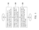
- the disclosure provides a method for playing a three-dimensional video, which includes the following steps.
- a disparity velocity or a disparity acceleration for at least one continuous video in the three-dimensional video is calculated.
- a visual fatigue estimating value of a viewer is calculated according to the disparity velocity or the disparity acceleration.
- a subsequent playback of the three-dimensional video is controlled according to the visual fatigue estimating value.
- the disclosure provides a control system adapted to control a playback of a three-dimensional video.
- the control system includes a three-dimensional video stream input unit, a disparity estimation unit, a visual fatigue estimation unit, a fatigue recovery control unit and a three-dimensional video stream display unit.
- the disparity estimation unit is coupled to the three-dimensional video stream input unit, and the disparity estimation unit calculates a disparity velocity or a disparity acceleration for at least one continuous video in the three-dimensional video.
- the visual fatigue estimation unit is coupled to the disparity estimation unit, and the visual fatigue estimation unit calculates a visual fatigue estimating value of a viewer according to the disparity velocity or the disparity acceleration.
- the fatigue recovery control unit is coupled to the three-dimensional video stream input unit and the visual fatigue estimation unit, and the fatigue recovery control unit controls a subsequent playback of the three-dimensional video according to the visual fatigue estimating value.
- the three-dimensional video stream display unit is coupled to the fatigue recovery control unit.
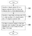
- FIG. 1 is a flowchart diagram illustrating a method for playing a three-dimensional video according to an embodiment of the disclosure.
- FIG. 2 is a diagram illustrating the relationship between a time and a visual fatigue.
- FIG. 3 is a schematic block diagram illustrating a control system according to an embodiment of the disclosure.
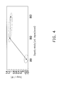
- FIG. 4 is a diagram illustrating the relationship between a disparity velocity and a change of High Frequency Component (HFC) of a subject.
- HFC High Frequency Component
- FIG. 5 and FIG. 6 are diagrams illustrating the relationship between a disparity velocity and a subjective fatigue (score) of a subject, and the relationship between a disparity range and a subjective fatigue (score) of a subject, respectively.
- FIG. 1 is a flowchart diagram illustrating a method for playing a three-dimensional video according to an embodiment of the disclosure.
- the method for playing a three-dimensional video in the disclosure includes the following steps. Firstly, a disparity velocity (DS) or a disparity acceleration (DA) for at least one continuous video in the three-dimensional video is calculated (step S 10 ). Then, a visual fatigue estimating value (Fa) of a viewer is calculated according to the disparity velocity (DS) or the disparity acceleration (DA) (step S 20 ). Afterwards, a subsequent playback of the three-dimensional video is controlled according to the visual fatigue estimating value, so as to reduce the visual fatigue of the viewer (step S 30 ).
- DS disparity velocity
- DA disparity acceleration
- the visual fatigue estimating value (Fa) may be calculated and obtained according to the disparity velocity (DS) for the at least one continuous video in the three-dimensional video.
- the disparity velocity (DS) can be defined as a change of a disparity range within a time unit.
- the visual fatigue estimating value (Fa) may be calculated through Formula (1) and Formula (2) as follow, in which fa is a visual fatigue estimating value of the viewer after watching at each of time units in the continuous video, Fa is an overall visual fatigue estimating value of the viewer after watching the continuous video, and T is a time.
- fa f ( DS ) (1)
- Fa f ( fa,T ) (2)
- the visual fatigue estimating value (fa) is related to the disparity velocity (DS)
- the overall visual fatigue estimating value (Fa) is related to the visual fatigue estimating value (fa) and the time (T).
- FIG. 2 is a diagram illustrating the relationship between a time and a visual fatigue.
- a specific continuous video in the three-dimensional video may be firstly selected (that is, from time T 1 to time T 2 ), and the visual fatigue estimating value (fa) at each of the time units is cumulated from time T 1 to time T 2 , so as to obtain the overall visual fatigue estimating value (Fa) related to the disparity velocity (DS).
- DS disparity velocity
- the method for calculating the visual fatigue estimating value (Fa) in the disclosure is not limited to Formula (1) and Formula (2) described above.
- the visual fatigue estimating value (Fa) may be calculated and obtained according to the disparity acceleration (DA) for the at least one continuous video in the three-dimensional video.
- the disparity acceleration (DA) can be defined as a change of the disparity velocity (DS) within a time unit.
- the visual fatigue estimating value (Fa) may be calculated through Formula (3) and Formula (4) as follow, in which fa is a visual fatigue estimating value of the viewer after watching at each of the time units in the continuous video, Fa is an overall visual fatigue estimating value of the viewer after watching the continuous video, and T is a time.
- fa f ( DA ) (3)
- Fa f ( fa,T ) (4)
- a specific continuous video in the three-dimensional video may be firstly selected (that is, from time T 1 to time T 2 ), and the visual fatigue estimating value (fa) at each of the time units is cumulated from time T 1 to time T 2 , so as to obtain the overall visual fatigue estimating value (Fa) related to the disparity acceleration (DA).
- parameters such as time (T), temporal weight (R T ), disparity velocity weight (V i ), disparity range weight (W d ), disparity mean position (P) and disparity direction (DD), may also served as the parameters for calculating the overall visual fatigue estimating value (Fa).
- the visual fatigue estimating value (Fa) may be calculated through Formula (5) and Formula (6) as follow, in which X in Formula (5) can be at least one of the afore-described disparity acceleration (DA), time (T), temporal weight (R T ), disparity velocity weight (V i ), disparity range weight (W d ), disparity mean position (P), disparity direction (DD), lateral velocity, brightness and contrast, while fa is the visual fatigue estimating value of the viewer after watching at each of the time units in the continuous video, and Fa is the overall visual fatigue estimating value of the viewer after watching the continuous video.
- fa f ( DS,X ) (5)
- Fa f ( fa,T ) (6)
- a specific continuous video in the three-dimensional video may be firstly selected (that is, from time T 1 to time T 2 ), and the visual fatigue estimating value (fa) at each of the time units is cumulated from time T 1 to time T 2 , so as to obtain the overall visual fatigue estimating value (Fa) related to the disparity velocity (DS) and the parameter (X).
- the visual fatigue estimating value (Fa) may also be calculated through Formula (7) and Formula (8) as follow, in which X in Formula (7) can be at least one of the afore-described disparity velocity (DS), time (T), temporal weight (R T ), disparity velocity weight (V), disparity range weight (W d ), disparity mean position (P), disparity direction (DD), lateral velocity, brightness and contrast, while fa is the visual fatigue estimating value of the viewer after watching at each of the time units in the continuous video, and Fa is the overall visual fatigue estimating value of the viewer after watching the continuous video.
- fa f ( DA,X ) (7)
- Fa f ( fa,T ) (8)
- a specific continuous video in the three-dimensional video may be firstly selected (that is, from time T 1 to time T 2 ), and the visual fatigue estimating value (fa) at each of the time units is cumulated from time T 1 to time T 2 , so as to obtain the overall visual fatigue estimating value (Fa) related to the disparity acceleration (DA) and the parameter (X).
- the disclosure provides a control system 100 to implement the afore-described method for playing the three-dimensional video, in order to control the playback of the three-dimensional video and effectively control the visual fatigue of the viewer.
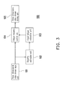
- FIG. 3 is a schematic block diagram illustrating a control system according to an embodiment of the disclosure.
- the control system 100 includes a three-dimensional video stream input unit 101 , a disparity estimation unit 102 , a visual fatigue estimation unit 103 , a fatigue recovery control unit 104 and a three-dimensional video stream display unit 105 .
- the disparity estimation unit 102 is coupled to the three-dimensional video stream input unit 101 , and the disparity estimation unit 102 calculates the disparity velocity (DS) or the disparity acceleration (DA) for the at least one continuous video in the three-dimensional video.
- DS disparity velocity
- DA disparity acceleration
- the visual fatigue estimation unit 103 is coupled to the disparity estimation unit 102 , and the visual fatigue estimation unit 103 calculates the visual fatigue estimating value of the viewer according to the disparity velocity (DS) or the disparity acceleration (DA).
- the fatigue recovery control unit 104 is coupled to the three-dimensional video stream input unit 101 and the visual fatigue estimation unit 103 .
- the fatigue recovery control unit 104 controls the subsequent playback of the three-dimensional video according to the visual fatigue estimating value.
- the three-dimensional video stream display unit 105 is coupled to the fatigue recovery control unit 104 .
- the three-dimensional video stream input unit 101 reads a three-dimensional video stream from a video storage medium or an internet video stream into the control system 100 .
- the three-dimensional video stream read by the three-dimensional video stream input unit 101 can be a three-dimensional video stream with single view or a three-dimensional video stream with multi view.
- the disparity estimation unit 102 divides the three-dimensional video stream into a plurality of video streams, and calculates the disparity velocity (DS) and/or the disparity acceleration (DA) for the video stream at each of the time units.
- each of the time units is two seconds, for instance.
- each of the time units is corresponded to one or more group of pictures (GOP) in the three-dimensional video, for instance.
- the method for the disparity estimation unit 102 to divide the three-dimensional video stream is not limited in the disclosure.
- the disparity estimation unit 102 calculates one or several disparity velocities (DS) and/or the disparity accelerations (DA) for the video stream after being divided by each of the time units. For example, the disparity estimation unit 102 may calculate one disparity velocity (DS) for the video stream at each of the time units. Alternatively, the disparity estimation unit 102 may calculate the disparity velocity (DS), a maximum disparity velocity (DS max ) and/or a minimum disparity velocity (DS min ) for the video stream at each of the time units, or else, the disparity estimation unit 102 may calculate the disparity acceleration (DA) for the video stream at each of the time units. In other embodiments, the disparity estimation unit 102 may further calculate other different parameters such as the disparity range (D), the lateral velocity, the content brightness or the contrast, for the video stream at each of the time units.
- D disparity range
- D the lateral velocity
- the calculation of the disparity velocity (DS) and/or the disparity acceleration (DA) through the disparity estimation unit 102 is to perform on all or a part of regions in the continuous video.
- the disparity estimation unit 102 can only calculate the disparity velocity (DS) and/or the disparity acceleration (DA) of the central region in the continuous video, or can only calculate the disparity velocity (DS) and/or the disparity acceleration (DA) of a dynamic body object in the continuous video.
- the disparity velocity (DS) and/or the disparity acceleration (DA) calculated by the disparity estimation unit 102 may be transferred to the visual fatigue estimation unit 103 .
- the visual fatigue estimation unit 103 calculates the overall visual fatigue estimating value (Fa) according to the disparity velocity (DS) and/or the disparity acceleration (DA).
- the visual fatigue estimation unit 103 transfers the calculated overall visual fatigue estimating value (Fa) to the fatigue recovery control unit 104 , in order for the fatigue recovery control unit 104 to control the subsequent playback of the three-dimensional video stream display unit 105 according to the overall visual fatigue estimating value (Fa), thereby effectively reducing the visual fatigue of the viewer.
- the fatigue recovery control unit 104 is capable of reducing the visual fatigue of the viewer by means such as decreasing the disparity range, decreasing the disparity velocity, decreasing the disparity acceleration, lowering the display contrast, lowering the display brightness, varying the playback velocity, directly switching to the two-dimensional display or generating an alter to notice the viewer.
- the fatigue recovery control unit 104 is capable of enhancing the three-dimensional perception effect of the images by means such as increasing the disparity range, increasing the disparity velocity, increasing the disparity acceleration.
- the three-dimensional video stream display unit 105 displays the images after being processed by the fatigue recovery control unit 104 to the viewer.
- the disparity estimation unit 102 (as shown in FIG. 3 ) is employed to directly retrieve the disparity velocity (DS) of the video stream within a certain time in the three-dimensional video, so as to calculate the visual fatigue estimating values (fa Fa).
- the disparity velocity (DS) can be the mean disparity velocity or the maximum disparity velocity within the certain time, for instance.
- the disparity estimation unit 102 (as shown in FIG. 3 ) is employed to calculate the disparity velocity (DS) of the video stream for each of the time units within a certain time interval in the three-dimensional video, and to calculate the accumulation of visual fatigue within the certain time interval, so as to serve as the visual fatigue estimating value Fa.
- the disparity estimation unit 102 (as shown in FIG. 3 ) is employed to calculate the disparity velocity (DS) of the video stream for each of the time units within a certain time interval in the three-dimensional video. Since the accumulation of visual fatigue is accelerated as the viewing time increases, different temporal weights (R T ) may be given in accordance with the time point for each of the video streams. In other words, a certain video stream firstly being played is given with a lower temporal weight (R T ), and a certain video stream subsequently being played is given with a higher temporal weight (R T ), while calculating the visual fatigue estimating value (Fa). Afterwards, the visual fatigue estimating value (Fa) within such time interval is calculated.
- the disparity estimation unit 102 (as shown in FIG. 3 ) is employed to calculate the disparity velocity (DS) of the video stream for each of the time units within a certain time interval in the three-dimensional video.
- the disparity velocity (DS) of the video stream for each of the time units within the certain time interval is not identical to each other, and the relationship between the visual fatigue estimating value (Fa) and the disparity velocity (DS) is not equally proportional (for example, when the disparity velocity (DS) reaches above a specific value, and the visual fatigue estimating value (Fa) increases substantially)
- the method for the visual fatigue estimating value (fa) may give different disparity velocity weights (V i ) according to the magnitude of the disparity velocity (DS).
- FIG. 4 is a diagram illustrating the relationship between a disparity velocity and a change of High Frequency Component (HFC) of a subject.
- HFC High Frequency Component
- FIG. 4 through the data from the performed ergonomic test, the relationship between the change of HFC of the subject being detected by ANOVA and the disparity velocity (such as DS 1 , DS 2 and D 3 ) is non-linear in the embodiment.
- HFC is defined between 1.0 Hz to 2.1 Hz or 1.0 Hz to 2.3 Hz, where HFC is related to the mechanical elasticity of crystalline lens, ciliary muscle or circular muscle of a human eye.
- the relationship between the disparity velocity (DS) and the fatigue of ciliary muscle in the human eye is non-proportional.
- Example 4 watches a 24 inches auto-stereoscopic 3D displayer with a 2-view lenticular plate and dual view, and the disparity velocity (DS) of the dynamic body object displayed by the 3D displayer may be DS 1 , DS 2 and DS 3 . According to the detection result, it can be seen that the disparity velocity (DS) of the dynamic body object has a significant impact on the fatigue of ciliary muscle in the human eye, in terms of the statistical consideration.
- the disparity velocity (DS) of the video stream for each of the time units within a certain time interval in the three-dimensional video is distributed between DS 1 to DS 3 .
- a low numerical value should be selected for the disparity velocity weight (V i ), so as to calculate the visual fatigue estimating value (fa) of such video stream.
- a high numerical value should be selected for the disparity velocity weight (V i ), so as to calculate the visual fatigue estimating value (fa) of another video stream.
- the visual fatigue estimating value (fa) can be a quadratic or higher-order function of the disparity velocity (DS) (i.e., the non-linear relationship).
- the disparity estimation unit 102 (as shown in FIG. 3 ) is employed to calculate the disparity velocity (DS) of the video stream for each of the time units within a certain time interval, and the temporal weight (R T ) may be further considered, other than the disparity velocity weight (V i ).
- the visual fatigue estimating value (fa) can be a quadratic or higher-order function of the disparity velocity (DS) (where the visual fatigue estimating value (fa) and the disparity velocity weight V i are in a non-linear relationship), and the visual fatigue estimating value (fa) can be a quadratic or higher-order function of the time (T) (where the visual fatigue estimating value (fa) and the temporal weight R T are in a non-linear relationship).
- the disparity estimation unit 102 (as shown in FIG. 3 ) is employed to calculate the disparity velocity (DS) of the video stream for each of the time units within a certain time interval. Within the time interval, the dynamic body object in each of the time units has different disparity velocities (DS) and different disparity ranges (D).
- the method for calculating the visual fatigue estimating value (fa) is to give each of the video streams with different disparity range weights (W d ) and different disparity velocity weights (V i ), while the method for calculating the visual fatigue estimating value (Fa) is to aggregate the visual fatigue estimating values (fa).
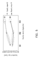
- FIG. 5 is a diagram illustrating the relationship among a disparity velocity, a disparity range and a subjective fatigue (score) of a subject.
- the disparity range (D) and the disparity velocity (such as DS 1 , DS 2 and D 3 ) is non-linear in the embodiment.
- the subject in Example 6 watches a 24 inches auto-stereoscopic 3D displayer with a 2-view lenticular plate and dual view
- the disparity velocity (DS) of the dynamic body object displayed by the 3D displayer may be DS 1 , DS 2 and DS 3
- the disparity range (D) of the dynamic body object displayed by the 3D displayer may be D 1 and D 2 .
- the disparity range (D) of the dynamic body object has a significant impact on the fatigue of ciliary muscle in the human eye
- the disparity velocity (DS) of the dynamic body object also has a significant impact on the fatigue of ciliary muscle in the human eye.
- the disparity velocity (DS) for each of the video streams within a certain time interval in the three-dimensional video is distributed between DS 1 to DS 3 , and the disparity range (D) is between D 1 and D 2 .
- a low numerical value should be selected for the disparity range weight (W d ).
- W d disparity range weight
- W d disparity range weight
- V i disparity velocity weight
- the visual fatigue estimating value (fa) can be a quadratic or higher-order function of the disparity velocity (DS) (i.e., the non-linear relationship), and the visual fatigue estimating value (fa) can be a quadratic or higher-order function of the disparity range (D) (i.e., the non-linear relationship).
- the disparity estimation unit 102 (as shown in FIG. 3 ) is employed to calculate the disparity velocity (DS) of the video stream for each of the time units within a certain time interval.
- the dynamic body object in each of the time units has different disparity velocities (DS) and different motion disparity ranges (D), where there is a strong interaction effect between the disparity velocity (DS) and the disparity range (D).
- DS disparity velocity
- D motion disparity range
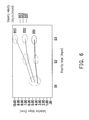
- FIG. 6 is a diagram illustrating the relationship among a disparity velocity, a disparity range and a subjective fatigue (score) of a subject.
- the disparity range such as D 1 , D 2 and D 3
- the disparity velocity such as DS 1 , DS 2 and D 3
- the subject in Example 7 watches a 50 inches non auto-stereoscopic 3D shutter displayer
- the disparity velocity (DS) of the dynamic body object displayed by the 3D displayer may be DS 1 , DS 2 and DS 3
- the disparity range (D) of the dynamic body object displayed by the 3D displayer may be D 1 , D 2 and D 3 .
- the subjective fatigue corresponding to the disparity velocity DS 1 is significantly lower, whereas the subjective fatigue corresponding to the disparity velocity DS 2 is between the subjective fatigues corresponding to the disparity velocities DS 1 and DS 3 .
- the disparity velocities i.e., DS 1 , DS 2 and DS 3
- the visual fatigue estimating value (fa) may apply to the calculation method.
- the disparity range (D) of the video stream falls nearby D 2 or D 3
- the disparity velocities i.e., DS 1 , DS 2 and DS 3
- the visual fatigue estimating value (fa) may apply to the another calculation method.
- the disparity estimation unit 102 (as shown in FIG. 3 ) is employed to calculate the disparity velocity (DS) and the disparity range (D) of the video stream for each of the time units within a certain time interval, and the temporal weight (R T ) of the video stream within each of the time units may be further considered in Example 8, other than the disparity velocity (DS) and the disparity range (D).
- Example 3 and Example 6 can be integrated to calculate the visual fatigue estimating value (fa).
- the visual fatigue estimating value (fa) can be a quadratic or higher-order function of the disparity velocity (DS) (i.e., the non-linear relationship), the visual fatigue estimating value (fa) can be a quadratic or higher-order function of the disparity range (D) (i.e., the non-linear relationship), and the visual fatigue estimating value (fa) can be a quadratic or higher-order function of the time (T) (i.e., the non-linear relationship).
- DS disparity velocity
- D disparity range
- T time
- the disparity estimation unit 102 (as shown in FIG. 3 ) is employed to calculate the disparity velocity (DS) of the video stream for each of the time units within a certain time interval, and the direction of the dynamic body object may be considered, which can be the direction towards a negative disparity velocity (namely, the direction gradually approaching to the viewer) or the direction towards a positive disparity direction (namely, the direction gradually away from the viewer), where different weights Q j are given to the different motion directions.
- the visual fatigue estimating value (fa) caused by the viewer is relatively high, so that a high numerical value should be selected for the weight Q j .
- the visual fatigue estimating value (fa) caused by the viewer is relatively low, so that a low numerical value should be selected for the weight Q j .
- the disparity estimation unit 102 (as shown in FIG. 3 ) is employed to calculate the disparity acceleration (DA) of the video stream for each of the time units within a certain time interval, and the disparity acceleration (DA) may be the mean disparity acceleration or the maximum disparity acceleration within the time interval, for instance.
- the method for calculating the disparity acceleration (DA) in Example 10 is similar to the method for calculating the disparity velocity (DS) in Example 1 to Example 9, and thus the detailed description for the calculation method of the disparity acceleration (DA) will be omitted herein.
- the disclosure calculates the visual fatigue estimating value according to the disparity velocity or the disparity acceleration, the method and the control system in the disclosure are capable of reducing the visual fatigue of the viewer effectively.
Abstract
Description
fa=f(DS) (1)
Fa=f(fa,T) (2)
fa=f(DA) (3)
Fa=f(fa,T) (4)
fa=f(DS,X) (5)
Fa=f(fa,T) (6)
fa=f(DA,X) (7)
Fa=f(fa,T) (8)
Claims (16)
Priority Applications (1)
| Application Number | Priority Date | Filing Date | Title |
|---|---|---|---|
| US13/939,188 US9300942B2 (en) | 2012-10-18 | 2013-07-11 | Method and control system for three-dimensional video playback using visual fatigue estimation |
Applications Claiming Priority (5)
| Application Number | Priority Date | Filing Date | Title |
|---|---|---|---|
| US201261715792P | 2012-10-18 | 2012-10-18 | |
| CN201310073099.3A CN103780894B (en) | 2012-10-18 | 2013-03-07 | The anaglyph player method of tool visual fatigue estimation and control system |
| CN201310073099.3 | 2013-03-07 | ||
| CN201310073099 | 2013-03-07 | ||
| US13/939,188 US9300942B2 (en) | 2012-10-18 | 2013-07-11 | Method and control system for three-dimensional video playback using visual fatigue estimation |
Publications (2)
| Publication Number | Publication Date |
|---|---|
| US20140111626A1 US20140111626A1 (en) | 2014-04-24 |
| US9300942B2 true US9300942B2 (en) | 2016-03-29 |
Family
ID=50484985
Family Applications (1)
| Application Number | Title | Priority Date | Filing Date |
|---|---|---|---|
| US13/939,188 Active 2034-07-23 US9300942B2 (en) | 2012-10-18 | 2013-07-11 | Method and control system for three-dimensional video playback using visual fatigue estimation |
Country Status (1)
| Country | Link |
|---|---|
| US (1) | US9300942B2 (en) |
Cited By (2)
| Publication number | Priority date | Publication date | Assignee | Title |
|---|---|---|---|---|
| US20160344934A1 (en) * | 2015-05-20 | 2016-11-24 | Panasonic Intellectual Property Management Co., Lt | Image display device and image processing device |
| US10531066B2 (en) | 2015-06-30 | 2020-01-07 | Samsung Electronics Co., Ltd | Method for displaying 3D image and device for same |
Families Citing this family (2)
| Publication number | Priority date | Publication date | Assignee | Title |
|---|---|---|---|---|
| KR102153606B1 (en) * | 2013-08-13 | 2020-09-08 | 삼성전자주식회사 | Apparatus and method for estimating user fatigue degree of video content |
| CN110177299B (en) * | 2018-08-30 | 2021-04-30 | 深圳市野生动物园有限公司 | Video playing speed adjusting platform |
Citations (19)
| Publication number | Priority date | Publication date | Assignee | Title |
|---|---|---|---|---|
| US4647965A (en) | 1983-11-02 | 1987-03-03 | Imsand Donald J | Picture processing system for three dimensional movies and video systems |
| JPH04149037A (en) | 1990-10-12 | 1992-05-22 | Kawaguchiko Seimitsu Kk | Glass cutter |
| US5726704A (en) | 1993-08-26 | 1998-03-10 | Matsushita Electric Industrial Co., Ltd. | Stereoscopic image pickup and display apparatus |
| US6677939B2 (en) | 1999-07-08 | 2004-01-13 | Canon Kabushiki Kaisha | Stereoscopic image processing apparatus and method, stereoscopic vision parameter setting apparatus and method and computer program storage medium information processing method and apparatus |
| US20040057612A1 (en) | 1998-06-04 | 2004-03-25 | Olympus Optical Co., Ltd. | Visual image system |
| US6798406B1 (en) | 1999-09-15 | 2004-09-28 | Sharp Kabushiki Kaisha | Stereo images with comfortable perceived depth |
| CN1643939A (en) | 2002-03-27 | 2005-07-20 | 三洋电机株式会社 | Method and apparatus for processing three-dimensional images |
| US7417664B2 (en) | 2003-03-20 | 2008-08-26 | Seijiro Tomita | Stereoscopic image picking up and display system based upon optical axes cross-point information |
| US20090096863A1 (en) | 2007-10-10 | 2009-04-16 | Samsung Electronics Co., Ltd. | Method and apparatus for reducing fatigue resulting from viewing three-dimensional image display, and method and apparatus for generating data stream of low visual fatigue three-dimensional image |
| US7557824B2 (en) | 2003-12-18 | 2009-07-07 | University Of Durham | Method and apparatus for generating a stereoscopic image |
| US7623089B2 (en) | 2005-03-24 | 2009-11-24 | Seiko Epson Corporation | Stereo image display device and method |
| US7720308B2 (en) | 2002-09-27 | 2010-05-18 | Sharp Kabushiki Kaisha | 3-D image display unit, 3-D image recording device and 3-D image recording method |
| US20100275238A1 (en) * | 2009-04-27 | 2010-10-28 | Masato Nagasawa | Stereoscopic Video Distribution System, Stereoscopic Video Distribution Method, Stereoscopic Video Distribution Apparatus, Stereoscopic Video Viewing System, Stereoscopic Video Viewing Method, And Stereoscopic Video Viewing Apparatus |
| US20110063421A1 (en) | 2009-09-16 | 2011-03-17 | Fujifilm Corporation | Stereoscopic image display apparatus |
| US7944444B2 (en) | 2005-09-03 | 2011-05-17 | Samsung Electronics Co., Ltd. | 3D image processing apparatus and method |
| US20110142309A1 (en) * | 2008-05-12 | 2011-06-16 | Thomson Licensing, LLC | System and method for measuring potential eyestrain of stereoscopic motion pictures |
| US8045792B2 (en) | 2007-03-29 | 2011-10-25 | Samsung Electronics Co., Ltd. | Method and apparatus for controlling dynamic depth of stereo-view or multi-view sequence images |
| US20110267338A1 (en) | 2010-05-03 | 2011-11-03 | Kwangwoon University Industry-Academic Collaboration Foundation | Apparatus and method for reducing three-dimensional visual fatigue |
| US20120148147A1 (en) | 2010-06-07 | 2012-06-14 | Masami Ogata | Stereoscopic image display system, disparity conversion device, disparity conversion method and program |
-
2013
- 2013-07-11 US US13/939,188 patent/US9300942B2/en active Active
Patent Citations (22)
| Publication number | Priority date | Publication date | Assignee | Title |
|---|---|---|---|---|
| US4647965A (en) | 1983-11-02 | 1987-03-03 | Imsand Donald J | Picture processing system for three dimensional movies and video systems |
| JPH04149037A (en) | 1990-10-12 | 1992-05-22 | Kawaguchiko Seimitsu Kk | Glass cutter |
| US5726704A (en) | 1993-08-26 | 1998-03-10 | Matsushita Electric Industrial Co., Ltd. | Stereoscopic image pickup and display apparatus |
| US20040057612A1 (en) | 1998-06-04 | 2004-03-25 | Olympus Optical Co., Ltd. | Visual image system |
| US6996267B2 (en) | 1998-06-04 | 2006-02-07 | Olympus Optical Co., Ltd. | Visual image system |
| JP4149037B2 (en) | 1998-06-04 | 2008-09-10 | オリンパス株式会社 | Video system |
| US6677939B2 (en) | 1999-07-08 | 2004-01-13 | Canon Kabushiki Kaisha | Stereoscopic image processing apparatus and method, stereoscopic vision parameter setting apparatus and method and computer program storage medium information processing method and apparatus |
| US6798406B1 (en) | 1999-09-15 | 2004-09-28 | Sharp Kabushiki Kaisha | Stereo images with comfortable perceived depth |
| CN1643939A (en) | 2002-03-27 | 2005-07-20 | 三洋电机株式会社 | Method and apparatus for processing three-dimensional images |
| EP2357839A2 (en) | 2002-03-27 | 2011-08-17 | Sanyo Electric Co., Ltd. | Method and apparatus for processing three-dimensional images |
| US7720308B2 (en) | 2002-09-27 | 2010-05-18 | Sharp Kabushiki Kaisha | 3-D image display unit, 3-D image recording device and 3-D image recording method |
| US7417664B2 (en) | 2003-03-20 | 2008-08-26 | Seijiro Tomita | Stereoscopic image picking up and display system based upon optical axes cross-point information |
| US7557824B2 (en) | 2003-12-18 | 2009-07-07 | University Of Durham | Method and apparatus for generating a stereoscopic image |
| US7623089B2 (en) | 2005-03-24 | 2009-11-24 | Seiko Epson Corporation | Stereo image display device and method |
| US7944444B2 (en) | 2005-09-03 | 2011-05-17 | Samsung Electronics Co., Ltd. | 3D image processing apparatus and method |
| US8045792B2 (en) | 2007-03-29 | 2011-10-25 | Samsung Electronics Co., Ltd. | Method and apparatus for controlling dynamic depth of stereo-view or multi-view sequence images |
| US20090096863A1 (en) | 2007-10-10 | 2009-04-16 | Samsung Electronics Co., Ltd. | Method and apparatus for reducing fatigue resulting from viewing three-dimensional image display, and method and apparatus for generating data stream of low visual fatigue three-dimensional image |
| US20110142309A1 (en) * | 2008-05-12 | 2011-06-16 | Thomson Licensing, LLC | System and method for measuring potential eyestrain of stereoscopic motion pictures |
| US20100275238A1 (en) * | 2009-04-27 | 2010-10-28 | Masato Nagasawa | Stereoscopic Video Distribution System, Stereoscopic Video Distribution Method, Stereoscopic Video Distribution Apparatus, Stereoscopic Video Viewing System, Stereoscopic Video Viewing Method, And Stereoscopic Video Viewing Apparatus |
| US20110063421A1 (en) | 2009-09-16 | 2011-03-17 | Fujifilm Corporation | Stereoscopic image display apparatus |
| US20110267338A1 (en) | 2010-05-03 | 2011-11-03 | Kwangwoon University Industry-Academic Collaboration Foundation | Apparatus and method for reducing three-dimensional visual fatigue |
| US20120148147A1 (en) | 2010-06-07 | 2012-06-14 | Masami Ogata | Stereoscopic image display system, disparity conversion device, disparity conversion method and program |
Non-Patent Citations (7)
| Title |
|---|
| "Office Action of Chinese Counterpart Application", issued on May 14, 2015, p. 1-p. 5. |
| Geng Sun et al., "Evaluating Method for Controlling Depth Perception in Stereoscopic Cinematography," SPIE Proceedings vol. 7237, Feb. 12, 2009, pp. 1-12. |
| Hyung-Chul O. Li et al., "Measurement of 3D Visual Fatigue Using Event-Related Potential (ERP): 3D Oddball Paradigm," 3DTV Conference: The True Vision-Capture, Transmission and Display of 3D Video, May 28-30, 2008, pp. 213-216. |
| Kazuhiko Ukai et al., "Visual fatigue caused by viewing stereoscopic motion images: Background, theories, and obsertvations," Health and Safety Aspects of Visual Displays, vol. 29, Issue 2, Mar. 2008, pp. 106-116. |
| Manuel Lang et al., "Nonlinear Disparity Mapping for Stereoscopic 3D," ACM Transactions on Graphics (TOG)-Proceedings of ACM SIGGRAPH, vol. 29, Issue 4, Jul. 2010, pp. 1-10. |
| Marc Lambooij et al., "Visual Discomfort and Visual Fatigue of Stereoscopic Displays: A Review," Journal of Imaging Science and Technology, vol. 53, No. 3, May 2009, pp. 30201-1-30201-14. |
| Yu-Ting Lin et al., "Evaluation of Image Quality and Subjective Visual Fatigue in Autostereoscopic Displays for 3D Dynamic Image Design," International Meeting on Information Display DIGEST, Aug. 28-31, 2012, pp. 1-2. |
Cited By (3)
| Publication number | Priority date | Publication date | Assignee | Title |
|---|---|---|---|---|
| US20160344934A1 (en) * | 2015-05-20 | 2016-11-24 | Panasonic Intellectual Property Management Co., Lt | Image display device and image processing device |
| US9716834B2 (en) * | 2015-05-20 | 2017-07-25 | Panasonic Intellectual Property Management Co., Ltd. | Image display device and image processing device |
| US10531066B2 (en) | 2015-06-30 | 2020-01-07 | Samsung Electronics Co., Ltd | Method for displaying 3D image and device for same |
Also Published As
| Publication number | Publication date |
|---|---|
| US20140111626A1 (en) | 2014-04-24 |
Similar Documents
| Publication | Publication Date | Title |
|---|---|---|
| JP6106586B2 (en) | Method and apparatus for customizing 3D effect of 3D content | |
| US10154244B2 (en) | 3D system including a marker mode | |
| US9338427B2 (en) | Scaling pixel depth values of user-controlled virtual object in three-dimensional scene | |
| US8514225B2 (en) | Scaling pixel depth values of user-controlled virtual object in three-dimensional scene | |
| EP2532166B1 (en) | Method, apparatus and computer program for selecting a stereoscopic imaging viewpoint pair | |
| US9300942B2 (en) | Method and control system for three-dimensional video playback using visual fatigue estimation | |
| CN105894567B (en) | Scaling pixel depth values of user-controlled virtual objects in a three-dimensional scene | |
| JP2011055421A5 (en) | ||
| US11350080B2 (en) | Methods and apparatus for displaying images | |
| US8745186B2 (en) | Network streaming of a video media from a media server to a media client | |
| JP2016201714A5 (en) | ||
| JP2012169759A (en) | Display device and display method | |
| JP2011176541A (en) | Three-dimensional video processing apparatus and method, and program thereof | |
| CA2783588C (en) | Method and apparatus for optimal motion reproduction in stereoscopic digital cinema | |
| US11652973B2 (en) | 3D system | |
| US20170142392A1 (en) | 3d system including additional 2d to 3d conversion | |
| CN103780894A (en) | Three-dimensional film playing method with visual fatigue estimation and control system | |
| US10121280B2 (en) | 3D system including rendering with three dimensional transformation | |
| CN109547763A (en) | The real parallax real-time control method of the solid of virtual reality system | |
| CN105306918A (en) | Processing method and device based on stereoscopic display | |
| KR20120090271A (en) | Image processing apparatus and control method thereof | |
| Masia et al. | Perceptually-optimized content remapping for automultiscopic displays | |
| WO2017083509A1 (en) | Three dimensional system | |
| WO2013015217A1 (en) | Stereoscopic image processing device and stereoscopic image processing method | |
| US20170142390A1 (en) | 3d system including lens modeling |
Legal Events
| Date | Code | Title | Description |
|---|---|---|---|
| AS | Assignment |
Owner name: INDUSTRIAL TECHNOLOGY RESEARCH INSTITUTE, TAIWAN Free format text: ASSIGNMENT OF ASSIGNORS INTEREST;ASSIGNORS:ZENG, WEN-JUN;LIN, MING-HUI;LIN, YU-TING;REEL/FRAME:030820/0828 Effective date: 20130703 |
|
| STCF | Information on status: patent grant |
Free format text: PATENTED CASE |
|
| MAFP | Maintenance fee payment |
Free format text: PAYMENT OF MAINTENANCE FEE, 4TH YEAR, LARGE ENTITY (ORIGINAL EVENT CODE: M1551); ENTITY STATUS OF PATENT OWNER: LARGE ENTITY Year of fee payment: 4 |
|
| MAFP | Maintenance fee payment |
Free format text: PAYMENT OF MAINTENANCE FEE, 8TH YEAR, LARGE ENTITY (ORIGINAL EVENT CODE: M1552); ENTITY STATUS OF PATENT OWNER: LARGE ENTITY Year of fee payment: 8 |