US9242274B2 - Pre-charged CMUTs for zero-external-bias operation - Google Patents
Pre-charged CMUTs for zero-external-bias operation Download PDFInfo
- Publication number
- US9242274B2 US9242274B2 US13/649,003 US201213649003A US9242274B2 US 9242274 B2 US9242274 B2 US 9242274B2 US 201213649003 A US201213649003 A US 201213649003A US 9242274 B2 US9242274 B2 US 9242274B2
- Authority
- US
- United States
- Prior art keywords
- cmut
- electrode
- substrate
- plate
- bias
- Prior art date
- Legal status (The legal status is an assumption and is not a legal conclusion. Google has not performed a legal analysis and makes no representation as to the accuracy of the status listed.)
- Expired - Fee Related, expires
Links
- 238000004519 manufacturing process Methods 0.000 claims abstract description 8
- 238000005468 ion implantation Methods 0.000 claims abstract description 4
- 239000000758 substrate Substances 0.000 claims description 23
- 238000000034 method Methods 0.000 claims description 9
- 238000002347 injection Methods 0.000 abstract description 4
- 239000007924 injection Substances 0.000 abstract description 4
- 238000006073 displacement reaction Methods 0.000 description 13
- 238000005259 measurement Methods 0.000 description 12
- 230000007774 longterm Effects 0.000 description 7
- 230000005684 electric field Effects 0.000 description 4
- XUIMIQQOPSSXEZ-UHFFFAOYSA-N Silicon Chemical compound [Si] XUIMIQQOPSSXEZ-UHFFFAOYSA-N 0.000 description 3
- 238000013461 design Methods 0.000 description 3
- 238000002474 experimental method Methods 0.000 description 3
- 229910052710 silicon Inorganic materials 0.000 description 3
- 239000010703 silicon Substances 0.000 description 3
- VYPSYNLAJGMNEJ-UHFFFAOYSA-N Silicium dioxide Chemical compound O=[Si]=O VYPSYNLAJGMNEJ-UHFFFAOYSA-N 0.000 description 2
- 238000003384 imaging method Methods 0.000 description 2
- 238000009413 insulation Methods 0.000 description 2
- 238000001228 spectrum Methods 0.000 description 2
- 238000013459 approach Methods 0.000 description 1
- 238000010009 beating Methods 0.000 description 1
- 230000005540 biological transmission Effects 0.000 description 1
- 238000012512 characterization method Methods 0.000 description 1
- 230000005574 cross-species transmission Effects 0.000 description 1
- 238000002059 diagnostic imaging Methods 0.000 description 1
- 235000012489 doughnuts Nutrition 0.000 description 1
- 230000000694 effects Effects 0.000 description 1
- 230000005284 excitation Effects 0.000 description 1
- 238000002847 impedance measurement Methods 0.000 description 1
- 239000012212 insulator Substances 0.000 description 1
- 238000012544 monitoring process Methods 0.000 description 1
- 239000013307 optical fiber Substances 0.000 description 1
- 230000005855 radiation Effects 0.000 description 1
- 238000000926 separation method Methods 0.000 description 1
- 235000012239 silicon dioxide Nutrition 0.000 description 1
- 239000000377 silicon dioxide Substances 0.000 description 1
- 238000003860 storage Methods 0.000 description 1
- 238000012285 ultrasound imaging Methods 0.000 description 1
Images


Classifications
-
- B—PERFORMING OPERATIONS; TRANSPORTING
- B06—GENERATING OR TRANSMITTING MECHANICAL VIBRATIONS IN GENERAL
- B06B—METHODS OR APPARATUS FOR GENERATING OR TRANSMITTING MECHANICAL VIBRATIONS OF INFRASONIC, SONIC, OR ULTRASONIC FREQUENCY, e.g. FOR PERFORMING MECHANICAL WORK IN GENERAL
- B06B1/00—Methods or apparatus for generating mechanical vibrations of infrasonic, sonic, or ultrasonic frequency
- B06B1/02—Methods or apparatus for generating mechanical vibrations of infrasonic, sonic, or ultrasonic frequency making use of electrical energy
- B06B1/0292—Electrostatic transducers, e.g. electret-type
Definitions
- This invention relates to capacitive micromachined ultrasonic transducers (CMUTs).
- CMUT signals in operation are typically AC electrical or acoustic signals.
- an applied AC electrical signal leads to emission of acoustic radiation from the CMUT (e.g., acoustic transmission), and an AC acoustic signal incident on a CMUT leads to generation of an AC electrical signal on the CMUT (e.g., acoustic reception).
- Capacitive micromachined ultrasonic transducers having a pre-charged floating electrode are provided. Such CMUTs can operate without an applied DC electrical bias. Charge can be provided to the floating electrode in various ways during or after fabrication, such as injection by an applied voltage, and injection by ion implantation. Such pre-charged CMUTs are of interest for all CMUT applications, especially those requiring low external DC biasing, and battery operated applications.
- Example applications include, but are not limited to medical imaging applications, such as 3D/4D real-time ultrasonic imaging, intracardiac ultrasound imaging, and 3D photoacoustic functional imaging. Reducing/eliminating DC bias can be helpful for mobile applications, for low power design, and for compliance with safety regulations for medical applications.
- FIGS. 1 a - b show cross section views of an exemplary embodiment of the invention.
- FIGS. 2 a - b show experimental results of CMUT resonant frequency before and after charging.
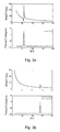
- FIGS. 3 a - b show experimental results of CMUT electrical impedance after charging.
- FIG. 4 shows long-term measurements of the short circuit resonance of a pre-charged CMUT.
- FIGS. 5 a - f show displacement of three pre-charged CMUTs (at zero external bias) measured by vibrometer.
- FIG. 6 shows resonant frequencies of a pitch-catch CMUT pair at various external DC biases.
- FIGS. 7 a - d show pitch catch measurements of a pair of pre-charged CMUTs.
- FIGS. 1 a - b show an exemplary embodiment of the invention.
- FIG. lb shows a view along line 116 of FIG. 1 a.
- the CMUT includes a CMUT plate 108 disposed above a substrate 110 .
- a plate electrode 120 is disposed on the CMUT plate 108 .
- a substrate electrode 104 is disposed on substrate 110 .
- the substrate electrode 104 is connected to a back side contact 112 by one or more vias 114 .
- the CMUT includes a floating electrode 102 that is not electrically connected to the substrate electrode 104 or to the plate electrode 120 . Charge is trapped on floating electrode 102 , and this trapped charge provides electrical DC bias for the CMUT (in full or in part).
- a standoff layer 106 defines the vertical separation between the CMUT plate 108 and the rest of the structure.
- substrate electrode 104 and floating electrode 102 are fabricated in silicon, and floating electrode 102 is insulated from the rest of the structure by oxide 118 (shown in gray on FIG. 1 a ).
- oxide 118 is not shown on the view of FIG. 1 b.
- Practice of the invention does not depend critically on how the CMUT is fabricated—any fabrication approach that provides an electrically insulated floating electrode in addition to conventional CMUT electrodes can be employed.
- a wafer bonding process with a thick-buried oxide layer is employed, which can result in oxide 118 being present as shown (e.g., surrounding substrate electrode 104 in addition to surrounding floating electrode 102 ).
- CMUT fabrication process can also be employed (e.g., sacrificial release).
- charges are trapped on the floating electrode.
- Such charge trapping can be accomplished in various ways. For example, an applied electrical bias can be increased to the point where charges spill over from another electrode (e.g., substrate electrode 104 ) onto floating electrode 102 .
- ion implantation can be employed to inject charge onto the floating electrode.
- the floating electrode can be disposed either on the substrate or on the CMUT plate.
- the following description relates to experiments on pre-charged CMUTs.
- CMUTs which have been pre-charged for zero-bias operation.
- the fabrication is based on a direct wafer bonding process with a thick buried oxide layer in the device silicon on insulator (SOI) wafer, which allows the realization of a donut shape bottom electrode surrounding a floating electrode in the center.
- SOI silicon on insulator
- the floating electrode is completely encapsulated by 3-um-thick silicon dioxide, and is thus electrically floating.
- the devices were pre-charged by applying a DC voltage higher than the pull-in voltage, which injects charges into the electrically floating portion and creates a sufficiently strong intrinsic electric field in the gap.
- one of the devices has 1800 um radius, 60 um thick plate, ⁇ 8 um gap, 3 um insulation layer, and a floating portion that is 50% in radius of the bottom electrode, and had a pull-in voltage that was 220 V originally.
- a DC charging voltage was applied onto the device, and increased gradually until it reached 550 V.
- the resonant frequency of this CMUT before and after charging is shown in FIG. 2 a .
- the curve before charging shows a pull-in voltage at 220 V, and before pull-in, the device had a maximum resonant frequency at 0 V. As the DC voltage deviates from 0 V, the resonant frequency drops due to the spring softening effect. After charging, the maximum resonant frequency moved to ⁇ 180 V, which shows that the charges injected into the device cancel the electric field created by the 180 V external DC bias. Therefore, we know that this device is charged up to an equivalent of 180 V DC bias when no external bias is applied, which is ⁇ 82% of the pull-in voltage.
- CMUT with pull-in voltage at 180 V was charged to an equivalent voltage of 250 V, which is larger than the pull-in voltage. Its resonant frequency before and after charging is shown in FIG. 2 b .
- the electric field created by the injected charge is so large that the device operates in the pull-in mode when there is no external DC bias applied.
- FIGS. 3 a - b The electrical impedance of the above-mentioned CMUTs at zero-external-bias is shown in FIGS. 3 a - b .
- FIG. 3 a relates to a CMUT that is charged to ⁇ 82% of the original pull-in voltage.
- FIG. 3 b relates to a CMUT charged to ⁇ 139% of the original pull-in voltage.
- conventional CMUTs operate with a constant DC voltage. Even though the pre-charged CMUTs operate with a constant charge, as opposed to constant voltage, we can see from FIGS. 3 a - b that these devices show a strong resonance in impedance when no external bias is applied.
- CMUT For long-term monitoring, we measured a CMUT with 1800 um radius, 30 um thick plate, ⁇ 33 um gap, 3 um insulation layer, and a floating portion that is 25% in radius of the bottom electrode, and a pull-in voltage that was 290 V originally. A maximum charging DC voltage of 680 V was applied on this device, and it is charged to an equivalent of 200 V. This CMUT was monitored over a time period of 19 months (results shown on FIG. 4 ), and the charge injected stays nearly constant. During this long-term period, this device has been repetitively stressed by both AC (up to 10 Vpp for pitch-catch) and DC (up to 320 V for impedance measurement) signals, and so far no shift in the equivalent charged voltage can be noticed.
- FIGS. 5 b , 5 d and 5 f show displacement measurements (maximum displacement as a function of AC input frequency) of three pre-charged CMUTs with no external bias using an optical fiber interferometer (Polytec, Irvine, Calif., USA).
- FIGS. 5 a , 5 c , and 5 e show 2D displacement plots corresponding to FIGS. 5 b , 5 d , and 5 e respectively.
- the device in FIGS. 5 a - b has 1800 um radius, 30 um thick plate, 33 um gap, and a floating portion that is 25% in radius of the bottom electrode.
- the device has a resonant frequency at 43.5 kHz, and gives a maximum displacement of 27 nm at 60 mVpp AC input.
- this device can achieve 140 dB relative to sound pressure level (SPL, i.e., 20 ⁇ Pa) with a mere 11.8 Vpp AC input, which gives ⁇ 1.77 um average displacement.
- SPL sound pressure level
- the device in FIGS. 5 c - d has a thicker plate (60 um), smaller gap (8 um), and a floating portion that is 50% in radius of the bottom electrode.
- the device performance under zero-external bias is equally spectacular: at the resonant frequency at 56.75 kHz, it gives a maximum displacement of 38 nm at 60 mVpp AC input. Assuming the displacement scales with the AC input, this device can achieve 140 dB re SPL with a mere 6.44 Vpp AC input, which gives ⁇ 1.36 um average displacement.
- FIGS. 5 e - f Similar results can be found in a CMUT charged to pull-in mode.
- the device in FIGS. 5 e - f has 1800 um radius, 60 um thick plate, 8 um gap, and a floating portion that is 50% in radius of the bottom electrode, and was charged to 139% of the original pull-in voltage.
- the device has a higher resonant frequency at 139.5 kHz, and gives a maximum displacement of 15 nm at 60 mVpp AC input.
- the pitch-catch measurement was carried out in either of two conditions: (1) no external bias on either of the 2 devices; or (2) a bias of 50 V applied to the receiving device to match the frequencies of the pair.
- the method of frequency matching between the pitch-catch device pair is based on the frequency measurement shown in FIG. 6 .
- This plot shows the resonant frequencies of the pitch-catch pair at various external DC biases.
- the 2 CMUTs operate at ⁇ 64 kHz and ⁇ 59 kHz respectively with no external bias.
- Frequencies of the 2 devices match when 50 V of external bias is applied to the receiving CMUT.
- FIGS. 7 a - d show pitch catch measurement of a pair of pre-charged CMUTs.
- FIGS. 7 a - b show the results of no external bias applied to either of the CMUTs
- FIGS. 7 c - d show results where a bias of 50 V is applied to the receiving device to match the frequencies of the pair.
- FIGS. 7 a and 7 c are the peak to peak value of the received signal at different frequencies
- FIGS. 7 b and 7 d are the corresponding time domain signals of the pitch-catch at ⁇ 64.5 kHz.
- the pitch-catch measurement is done with a distance of 30 cm between the devices, an AC signal of 20-cycle, 12 Vpp sinusoidal burst as excitation source, and a pre-amplifier of 40 dB on the receiving side. Due to the frequency mismatch of the pair of the devices, the pitch-catch signal with no-external-bias applied shows 2 peaks in the spectrum ( FIG. 7 a ), and the time domain signal contains some beating ( FIG. 7 b ). With a low external DC bias of 50 V applied to only 1 of the devices, the pitch catch spectrum in FIG. 7 c has a single peak, and the time domain signal in FIG. 7 d looks much cleaner.
- CMUTs are capable of doing pitch-catch under no external DC bias and can still give signals with good signal-to-noise ratio.
- CMUT complementary metal-oxide-semiconductor
- CMUT structure can simplify the circuit design in terms of external dc bias circuitry, mobile applications, low power design, and safety regulations for medical applications.
Abstract
Description
Claims (6)
Priority Applications (1)
| Application Number | Priority Date | Filing Date | Title |
|---|---|---|---|
| US13/649,003 US9242274B2 (en) | 2011-10-11 | 2012-10-10 | Pre-charged CMUTs for zero-external-bias operation |
Applications Claiming Priority (2)
| Application Number | Priority Date | Filing Date | Title |
|---|---|---|---|
| US201161545805P | 2011-10-11 | 2011-10-11 | |
| US13/649,003 US9242274B2 (en) | 2011-10-11 | 2012-10-10 | Pre-charged CMUTs for zero-external-bias operation |
Publications (2)
| Publication Number | Publication Date |
|---|---|
| US20130088118A1 US20130088118A1 (en) | 2013-04-11 |
| US9242274B2 true US9242274B2 (en) | 2016-01-26 |
Family
ID=48041630
Family Applications (1)
| Application Number | Title | Priority Date | Filing Date |
|---|---|---|---|
| US13/649,003 Expired - Fee Related US9242274B2 (en) | 2011-10-11 | 2012-10-10 | Pre-charged CMUTs for zero-external-bias operation |
Country Status (1)
| Country | Link |
|---|---|
| US (1) | US9242274B2 (en) |
Cited By (1)
| Publication number | Priority date | Publication date | Assignee | Title |
|---|---|---|---|---|
| US11173520B2 (en) | 2020-01-20 | 2021-11-16 | The Board Of Trustees Of The Leland Stanford Junior University | Pulse train excitation for capacative micromachined ultrasonic transducer |
Families Citing this family (4)
| Publication number | Priority date | Publication date | Assignee | Title |
|---|---|---|---|---|
| CA2895821A1 (en) * | 2012-12-21 | 2014-06-26 | Volcano Corporation | Focused rotational ivus transducer using single crystal composite material |
| JP6534190B2 (en) * | 2013-09-27 | 2019-06-26 | コーニンクレッカ フィリップス エヌ ヴェKoninklijke Philips N.V. | Ultrasonic transducer assembly and method for transmitting and receiving ultrasonic waves |
| DE102013223695B4 (en) | 2013-11-20 | 2016-09-22 | Fraunhofer-Gesellschaft zur Förderung der angewandten Forschung e.V. | METHOD FOR PRODUCING A CAPACITIVE ULTRASONIC TRANSDUCER AND ARRANGEMENT OF A MULTIPLE OF CAPACITIVE ULTRASONIC TRANSDUCERS |
| US11097312B2 (en) * | 2015-08-11 | 2021-08-24 | Koninklijke Philips N.V. | Capacitive micromachined ultrasonic transducers with increased lifetime |
Citations (10)
| Publication number | Priority date | Publication date | Assignee | Title |
|---|---|---|---|---|
| US4524247A (en) * | 1983-07-07 | 1985-06-18 | At&T Bell Laboratories | Integrated electroacoustic transducer with built-in bias |
| US4954789A (en) * | 1989-09-28 | 1990-09-04 | Texas Instruments Incorporated | Spatial light modulator |
| US20050219953A1 (en) | 2004-04-06 | 2005-10-06 | The Board Of Trustees Of The Leland Stanford Junior University | Method and system for operating capacitive membrane ultrasonic transducers |
| US7274623B2 (en) | 2004-04-06 | 2007-09-25 | Board Of Trustees Of The Deland Stanford Junior University | Method and system for operating capacitive membrane ultrasonic transducers |
| US20090322181A1 (en) | 2008-06-19 | 2009-12-31 | Hitachi, Ltd. | Ultrasonic transducer and method of manufacturing the same |
| US7675221B2 (en) | 2005-09-06 | 2010-03-09 | Hitachi, Ltd. | Ultrasonic transducer and manufacturing method thereof |
| US20100207485A1 (en) | 2007-09-17 | 2010-08-19 | Koninklijke Philips Electronics N.V. | Production of pre-collapsed capacitive micro-machined ultrasonic transducers and applications thereof |
| US20110040189A1 (en) | 2007-12-14 | 2011-02-17 | Koninklijke Philips Electronics N.V. | Collapsed mode operable cmut including contoured substrate |
| US20110227448A1 (en) * | 2010-03-18 | 2011-09-22 | Canon Kabushiki Kaisha | Apparatus and method for driving capacitive electromechanical transduction apparatus |
| US20120010538A1 (en) | 2007-09-17 | 2012-01-12 | Koninklijke Philips Electronics N.V. | Pre-collapsed cmut with mechanical collapse retention |
-
2012
- 2012-10-10 US US13/649,003 patent/US9242274B2/en not_active Expired - Fee Related
Patent Citations (10)
| Publication number | Priority date | Publication date | Assignee | Title |
|---|---|---|---|---|
| US4524247A (en) * | 1983-07-07 | 1985-06-18 | At&T Bell Laboratories | Integrated electroacoustic transducer with built-in bias |
| US4954789A (en) * | 1989-09-28 | 1990-09-04 | Texas Instruments Incorporated | Spatial light modulator |
| US20050219953A1 (en) | 2004-04-06 | 2005-10-06 | The Board Of Trustees Of The Leland Stanford Junior University | Method and system for operating capacitive membrane ultrasonic transducers |
| US7274623B2 (en) | 2004-04-06 | 2007-09-25 | Board Of Trustees Of The Deland Stanford Junior University | Method and system for operating capacitive membrane ultrasonic transducers |
| US7675221B2 (en) | 2005-09-06 | 2010-03-09 | Hitachi, Ltd. | Ultrasonic transducer and manufacturing method thereof |
| US20100207485A1 (en) | 2007-09-17 | 2010-08-19 | Koninklijke Philips Electronics N.V. | Production of pre-collapsed capacitive micro-machined ultrasonic transducers and applications thereof |
| US20120010538A1 (en) | 2007-09-17 | 2012-01-12 | Koninklijke Philips Electronics N.V. | Pre-collapsed cmut with mechanical collapse retention |
| US20110040189A1 (en) | 2007-12-14 | 2011-02-17 | Koninklijke Philips Electronics N.V. | Collapsed mode operable cmut including contoured substrate |
| US20090322181A1 (en) | 2008-06-19 | 2009-12-31 | Hitachi, Ltd. | Ultrasonic transducer and method of manufacturing the same |
| US20110227448A1 (en) * | 2010-03-18 | 2011-09-22 | Canon Kabushiki Kaisha | Apparatus and method for driving capacitive electromechanical transduction apparatus |
Cited By (3)
| Publication number | Priority date | Publication date | Assignee | Title |
|---|---|---|---|---|
| US11173520B2 (en) | 2020-01-20 | 2021-11-16 | The Board Of Trustees Of The Leland Stanford Junior University | Pulse train excitation for capacative micromachined ultrasonic transducer |
| US11260424B2 (en) | 2020-01-20 | 2022-03-01 | The Board Of Trustees Of The Leland Stanford Junior University | Contoured electrode for capacitive micromachined ultrasonic transducer |
| US11731164B2 (en) | 2020-01-20 | 2023-08-22 | The Board Of Trustees Of The Leland Stanford Junior University | Pulse train excitation for capacitive micromachined ultrasonic transducer |
Also Published As
| Publication number | Publication date |
|---|---|
| US20130088118A1 (en) | 2013-04-11 |
Similar Documents
| Publication | Publication Date | Title |
|---|---|---|
| US9242274B2 (en) | Pre-charged CMUTs for zero-external-bias operation | |
| KR101689346B1 (en) | Pre-collapsed cmut with mechanical collapse retention | |
| JP4730162B2 (en) | Ultrasonic transmitting / receiving device, ultrasonic probe, and manufacturing method thereof | |
| Logan et al. | Fabricating capacitive micromachined ultrasonic transducers with a novel silicon-nitride-based wafer bonding process | |
| Ho et al. | Long-term measurement results of pre-charged CMUTs with zero external bias operation | |
| JP6329491B2 (en) | Capacitive micromachined ultrasonic transducer device with charged voltage source | |
| US20140010052A1 (en) | Capacitive transducer | |
| US9242273B2 (en) | Method for operating CMUTs under high and varying pressure | |
| Lu et al. | High frequency piezoelectric micromachined ultrasonic transducer array for intravascular ultrasound imaging | |
| CN104117477B (en) | Capacitive transducer and method of manufacturing the same, detector and target information acquisition device | |
| WO2006013717A1 (en) | Capacitive micromachined ultrasonic transducer and method for manufacturing same | |
| US20140007693A1 (en) | Capacitive transducer | |
| US20160153939A1 (en) | Capacitive micromachined ultrasonic transducer and test object information acquiring apparatus including capacitive micromachined ultrasonic transducer | |
| CN103130178A (en) | Method for manufacturing capacitive micromachined ultrasonic transducer and apparatus configured to obtain subject information | |
| JP6632431B2 (en) | Ultrasonic transducer unit and information acquisition device including the same | |
| JP2017085257A (en) | Capacitive transducer and information acquisition device with the same | |
| JP2009272824A (en) | Ultrasonic wave vibrator cell, ultrasonic wave vibrator, and ultrasonic endoscope | |
| Mehdizadeh et al. | AlN on SOI pMUTs for ultrasonic power transfer | |
| US10016788B2 (en) | Method and device for driving capacitance transducer | |
| JP6763731B2 (en) | Ultrasonic transducer, its manufacturing method and ultrasonic imaging device | |
| US20170312782A1 (en) | Integrated acoustic transducer with reduced propagation of undesired acoustic waves | |
| Mahmud et al. | Improved CMUT structure and method of operation for dual-frequency acoustic angiography | |
| Wang et al. | A multi-frequency PMUT array based on ceramic PZT for endoscopic photoacoustic imaging | |
| Dew et al. | Outperforming piezoelectric ultrasonics with high-reliability single-membrane CMUT array elements | |
| Kawasaki et al. | Pre-charged collapse-mode capacitive micromachined ultrasonic transducer (CMUT) for broadband ultrasound power transfer |
Legal Events
| Date | Code | Title | Description |
|---|---|---|---|
| AS | Assignment |
Owner name: BOARD OF TRUSTEES OF THE LELAND STANFORD JUNIOR UN Free format text: ASSIGNMENT OF ASSIGNORS INTEREST;ASSIGNORS:HO, MIN-CHIEH;KUPNIK, MARIO;KHURI-YAKUB, BUTRUS T.;REEL/FRAME:029218/0285 Effective date: 20111011 |
|
| AS | Assignment |
Owner name: NATIONAL INSTITUTES OF HEALTH (NIH), U.S. DEPT. OF Free format text: CONFIRMATORY LICENSE;ASSIGNOR:THE BOARD OF TRUSTEES OF THE LELAND STANFORD JUNIOR UNIVERSITY;REEL/FRAME:030921/0650 Effective date: 20130730 |
|
| ZAAA | Notice of allowance and fees due |
Free format text: ORIGINAL CODE: NOA |
|
| ZAAB | Notice of allowance mailed |
Free format text: ORIGINAL CODE: MN/=. |
|
| STCF | Information on status: patent grant |
Free format text: PATENTED CASE |
|
| MAFP | Maintenance fee payment |
Free format text: PAYMENT OF MAINTENANCE FEE, 4TH YR, SMALL ENTITY (ORIGINAL EVENT CODE: M2551); ENTITY STATUS OF PATENT OWNER: SMALL ENTITY Year of fee payment: 4 |
|
| FEPP | Fee payment procedure |
Free format text: MAINTENANCE FEE REMINDER MAILED (ORIGINAL EVENT CODE: REM.); ENTITY STATUS OF PATENT OWNER: SMALL ENTITY |
|
| LAPS | Lapse for failure to pay maintenance fees |
Free format text: PATENT EXPIRED FOR FAILURE TO PAY MAINTENANCE FEES (ORIGINAL EVENT CODE: EXP.); ENTITY STATUS OF PATENT OWNER: SMALL ENTITY |
|
| STCH | Information on status: patent discontinuation |
Free format text: PATENT EXPIRED DUE TO NONPAYMENT OF MAINTENANCE FEES UNDER 37 CFR 1.362 |
|
| FP | Lapsed due to failure to pay maintenance fee |
Effective date: 20240126 |