US9228779B2 - Infrared float bar - Google Patents
Infrared float bar Download PDFInfo
- Publication number
- US9228779B2 US9228779B2 US12/792,294 US79229410A US9228779B2 US 9228779 B2 US9228779 B2 US 9228779B2 US 79229410 A US79229410 A US 79229410A US 9228779 B2 US9228779 B2 US 9228779B2
- Authority
- US
- United States
- Prior art keywords
- air
- web
- infrared
- lens
- bar
- Prior art date
- Legal status (The legal status is an assumption and is not a legal conclusion. Google has not performed a legal analysis and makes no representation as to the accuracy of the status listed.)
- Active, expires
Links
- 238000001816 cooling Methods 0.000 claims abstract description 55
- 238000005188 flotation Methods 0.000 claims abstract description 40
- 239000012530 fluid Substances 0.000 claims abstract description 25
- 208000028659 discharge Diseases 0.000 claims description 36
- 238000007599 discharging Methods 0.000 claims description 3
- 239000000463 material Substances 0.000 abstract description 49
- 238000001035 drying Methods 0.000 abstract description 47
- 238000012546 transfer Methods 0.000 abstract description 22
- 239000002904 solvent Substances 0.000 abstract description 18
- 238000001704 evaporation Methods 0.000 abstract description 4
- 230000008020 evaporation Effects 0.000 abstract description 3
- 238000007667 floating Methods 0.000 abstract description 3
- 239000003570 air Substances 0.000 description 268
- 238000010438 heat treatment Methods 0.000 description 21
- 230000004907 flux Effects 0.000 description 17
- 238000009826 distribution Methods 0.000 description 16
- 230000005855 radiation Effects 0.000 description 14
- 238000000576 coating method Methods 0.000 description 12
- 230000001105 regulatory effect Effects 0.000 description 12
- 239000011888 foil Substances 0.000 description 11
- 239000011248 coating agent Substances 0.000 description 10
- 239000000976 ink Substances 0.000 description 9
- 238000004891 communication Methods 0.000 description 8
- 239000010453 quartz Substances 0.000 description 8
- VYPSYNLAJGMNEJ-UHFFFAOYSA-N silicon dioxide Inorganic materials O=[Si]=O VYPSYNLAJGMNEJ-UHFFFAOYSA-N 0.000 description 8
- XLYOFNOQVPJJNP-UHFFFAOYSA-N water Substances O XLYOFNOQVPJJNP-UHFFFAOYSA-N 0.000 description 8
- 238000011109 contamination Methods 0.000 description 7
- 238000013461 design Methods 0.000 description 7
- 230000007246 mechanism Effects 0.000 description 6
- 239000000123 paper Substances 0.000 description 6
- 238000010521 absorption reaction Methods 0.000 description 5
- 230000015556 catabolic process Effects 0.000 description 5
- 239000000356 contaminant Substances 0.000 description 5
- 238000006731 degradation reaction Methods 0.000 description 5
- 238000013021 overheating Methods 0.000 description 5
- 239000000758 substrate Substances 0.000 description 5
- 230000005540 biological transmission Effects 0.000 description 4
- 238000010586 diagram Methods 0.000 description 4
- 230000000694 effects Effects 0.000 description 4
- 238000000034 method Methods 0.000 description 4
- 238000007639 printing Methods 0.000 description 4
- 238000009423 ventilation Methods 0.000 description 4
- 238000011084 recovery Methods 0.000 description 3
- 238000011144 upstream manufacturing Methods 0.000 description 3
- OKTJSMMVPCPJKN-UHFFFAOYSA-N Carbon Chemical compound [C] OKTJSMMVPCPJKN-UHFFFAOYSA-N 0.000 description 2
- 230000009471 action Effects 0.000 description 2
- 229910052799 carbon Inorganic materials 0.000 description 2
- 239000000446 fuel Substances 0.000 description 2
- 238000007603 infrared drying Methods 0.000 description 2
- 239000007788 liquid Substances 0.000 description 2
- 230000000116 mitigating effect Effects 0.000 description 2
- 239000011087 paperboard Substances 0.000 description 2
- 238000012545 processing Methods 0.000 description 2
- 239000007787 solid Substances 0.000 description 2
- 235000021538 Chard Nutrition 0.000 description 1
- 230000003213 activating effect Effects 0.000 description 1
- 239000000654 additive Substances 0.000 description 1
- 230000000996 additive effect Effects 0.000 description 1
- XAGFODPZIPBFFR-UHFFFAOYSA-N aluminium Chemical compound [Al] XAGFODPZIPBFFR-UHFFFAOYSA-N 0.000 description 1
- 229910052782 aluminium Inorganic materials 0.000 description 1
- 239000012080 ambient air Substances 0.000 description 1
- 238000013459 approach Methods 0.000 description 1
- 230000008901 benefit Effects 0.000 description 1
- 230000000903 blocking effect Effects 0.000 description 1
- 230000000295 complement effect Effects 0.000 description 1
- 230000006835 compression Effects 0.000 description 1
- 238000007906 compression Methods 0.000 description 1
- 239000012809 cooling fluid Substances 0.000 description 1
- 230000007547 defect Effects 0.000 description 1
- 238000001514 detection method Methods 0.000 description 1
- 239000010432 diamond Substances 0.000 description 1
- 229910003460 diamond Inorganic materials 0.000 description 1
- 230000003292 diminished effect Effects 0.000 description 1
- 238000010981 drying operation Methods 0.000 description 1
- 239000000428 dust Substances 0.000 description 1
- 230000005670 electromagnetic radiation Effects 0.000 description 1
- 238000005265 energy consumption Methods 0.000 description 1
- 239000002360 explosive Substances 0.000 description 1
- 231100001261 hazardous Toxicity 0.000 description 1
- 230000006872 improvement Effects 0.000 description 1
- 230000010354 integration Effects 0.000 description 1
- 238000012423 maintenance Methods 0.000 description 1
- 238000004519 manufacturing process Methods 0.000 description 1
- 238000005457 optimization Methods 0.000 description 1
- 239000003960 organic solvent Substances 0.000 description 1
- 239000002985 plastic film Substances 0.000 description 1
- 229920000642 polymer Polymers 0.000 description 1
- 230000002265 prevention Effects 0.000 description 1
- 230000008569 process Effects 0.000 description 1
- 238000002310 reflectometry Methods 0.000 description 1
- 230000000717 retained effect Effects 0.000 description 1
- 238000000926 separation method Methods 0.000 description 1
- 238000000935 solvent evaporation Methods 0.000 description 1
- 238000001228 spectrum Methods 0.000 description 1
- 229910001220 stainless steel Inorganic materials 0.000 description 1
- 239000010935 stainless steel Substances 0.000 description 1
- 230000000153 supplemental effect Effects 0.000 description 1
- WFKWXMTUELFFGS-UHFFFAOYSA-N tungsten Chemical compound [W] WFKWXMTUELFFGS-UHFFFAOYSA-N 0.000 description 1
- 229910052721 tungsten Inorganic materials 0.000 description 1
- 239000010937 tungsten Substances 0.000 description 1
Images


Classifications
-
- F—MECHANICAL ENGINEERING; LIGHTING; HEATING; WEAPONS; BLASTING
- F26—DRYING
- F26B—DRYING SOLID MATERIALS OR OBJECTS BY REMOVING LIQUID THEREFROM
- F26B3/00—Drying solid materials or objects by processes involving the application of heat
- F26B3/28—Drying solid materials or objects by processes involving the application of heat by radiation, e.g. from the sun
- F26B3/30—Drying solid materials or objects by processes involving the application of heat by radiation, e.g. from the sun from infrared-emitting elements
-
- B—PERFORMING OPERATIONS; TRANSPORTING
- B41—PRINTING; LINING MACHINES; TYPEWRITERS; STAMPS
- B41F—PRINTING MACHINES OR PRESSES
- B41F23/00—Devices for treating the surfaces of sheets, webs, or other articles in connection with printing
- B41F23/04—Devices for treating the surfaces of sheets, webs, or other articles in connection with printing by heat drying, by cooling, by applying powders
- B41F23/0403—Drying webs
- B41F23/0406—Drying webs by radiation
- B41F23/0413—Infra-red dryers
-
- F—MECHANICAL ENGINEERING; LIGHTING; HEATING; WEAPONS; BLASTING
- F26—DRYING
- F26B—DRYING SOLID MATERIALS OR OBJECTS BY REMOVING LIQUID THEREFROM
- F26B13/00—Machines and apparatus for drying fabrics, fibres, yarns, or other materials in long lengths, with progressive movement
- F26B13/10—Arrangements for feeding, heating or supporting materials; Controlling movement, tension or position of materials
- F26B13/101—Supporting materials without tension, e.g. on or between foraminous belts
- F26B13/104—Supporting materials without tension, e.g. on or between foraminous belts supported by fluid jets only; Fluid blowing arrangements for flotation dryers, e.g. coanda nozzles
-
- F—MECHANICAL ENGINEERING; LIGHTING; HEATING; WEAPONS; BLASTING
- F26—DRYING
- F26B—DRYING SOLID MATERIALS OR OBJECTS BY REMOVING LIQUID THEREFROM
- F26B3/00—Drying solid materials or objects by processes involving the application of heat
- F26B3/28—Drying solid materials or objects by processes involving the application of heat by radiation, e.g. from the sun
- F26B3/283—Drying solid materials or objects by processes involving the application of heat by radiation, e.g. from the sun in combination with convection
-
- Y—GENERAL TAGGING OF NEW TECHNOLOGICAL DEVELOPMENTS; GENERAL TAGGING OF CROSS-SECTIONAL TECHNOLOGIES SPANNING OVER SEVERAL SECTIONS OF THE IPC; TECHNICAL SUBJECTS COVERED BY FORMER USPC CROSS-REFERENCE ART COLLECTIONS [XRACs] AND DIGESTS
- Y02—TECHNOLOGIES OR APPLICATIONS FOR MITIGATION OR ADAPTATION AGAINST CLIMATE CHANGE
- Y02P—CLIMATE CHANGE MITIGATION TECHNOLOGIES IN THE PRODUCTION OR PROCESSING OF GOODS
- Y02P70/00—Climate change mitigation technologies in the production process for final industrial or consumer products
- Y02P70/10—Greenhouse gas [GHG] capture, material saving, heat recovery or other energy efficient measures, e.g. motor control, characterised by manufacturing processes, e.g. for rolling metal or metal working
Definitions
- Embodiments disclosed herein relate to an air float bar for use in positioning, drying or curing a continuous generally planar flexible material such as a web, printed web, newsprint, film material, or plastic sheet. More particularly, they pertain to an air float bar whose pressure pad area includes an infrared light source, such as an infrared bulb, a reflector surface and a lens to enhance accelerated infrared heating of web material to cause solvent evaporation, drying and/or curing. Electromagnetic infrared heat energy in combination with jets of air impinging upon the web surface provide for concentrated heating of the web material, thereby providing subsequent rapid evaporation, drying and/or curing from the surface of the material.
- an infrared light source such as an infrared bulb, a reflector surface and a lens to enhance accelerated infrared heating of web material to cause solvent evaporation, drying and/or curing.
- Electromagnetic infrared heat energy in combination with jets of air impinging upon the
- U.S. Pat. No. 5,035,066 (Wimberger) teaches the integration of an infrared emitter into a Coanda-type flotation air bar. Cooling air is brought through a channel assembly that encloses the emitter. A quartz lens is used to enclose the emitter while allowing transmission of electromagnetic energy in the range of infrared wavelengths to pass from the channel assembly enclosure to the web. In one embodiment, said cooling air, after passing around the emitter inside said channel assembly, is discharged through holes in a quartz lens of said emitter channel assembly.
- Cooling and prevention of contamination of the reflector is also desirable for the same reasons as discussed for the lens. If such contamination occurs, the infrared energy is absorbed by the quartz material of the emitter and quartz lens instead of being transmitted through said quartz to the web surface, which results in loss of drying and heat transfer efficiency, and also promotes thermal degradation as the design temperatures of the emitter and lens materials may easily be exceeded. Similarly, contamination will reduce the reflectivity of the reflector resulting in loss of drying and heat transfer efficiency and material thermal degradation.
- fast-cooling tungsten or carbon filament emitters as are available from Heraeus Noblelight of Hanau, Germany. These fast-cooling elements minimize the time necessary to bring the infrared heat flux and associated surface temperatures low enough avoid ignition of said combustible materials should the web stop or break during an upset to the drying process. Even with such quick cooling emitters, it is desirable to keep the exposed surfaces of the air float bar as cool as possible at all times to prevent possible ignition of said combustible materials, even when web stoppage or a web breakage upset may go undetected.
- the amount of heat effectively absorbed by the material is dependant on a number of key factors, including the temperature of the emitter, the geometry defining the infrared light paths to the materials, and the absorption characteristic of the materials to be dried. It is desired to select an emitter type such that its temperature will emit maximum electromagnetic energy flux in the range of wavelengths that correspond with the wavelengths of maximum absorption in the material to be dried.
- the materials typically include the base web substrate, and a coating comprised of solids, and a solvent such as water or an organic solvent, said solvent to be dried. Each of these materials exhibits an infrared absorption characteristic as a function of infrared wavelength, or spectra, which is to be considered in the selection of the type of emitter to be used.
- the coating or ink is not applied to the substrate uniformly in all areas. It such cases it is desirable to maximize the infrared energy flux to the areas having coating or ink while minimizing the energy flow to uncoated (unprinted) areas.
- the locations of the coated and uncoated areas are variable according to the product to be dried.
- One prior art method used to effect the direction of drying energy to areas requiring drying while limiting energy to areas not requiring drying prescribes the selection of the emitter such that it will provide high infrared heat flux at a range of wavelengths that match high absorption wavelengths for the solvent, while minimizing the emission of infrared energy at wavelengths where absorption in the dry solids and the substrate is low.
- Another prior art method arranges a plurality of emitter lamps in an array wherein the emitter lamps may be activated (energized) or deactivated (de-energized) to emit infrared energy approximately matching the physical location of the areas to be dried.
- this method of activating and deactivating a fixed array is only practically capable of directing drying energy on a spatially coarse scale.
- the infrared energy can be applied more or less in lanes along the length of the web to be dried, which does not address the need to limit drying heat to the unprinted areas that lie between printed areas along the direction of web travel.
- the embodiments disclosed herein offer an improvement over the prior art by guiding the cooling air in a path which maximizes the cooling of an emitter, an optional lens and reflector surfaces while providing additional convective heat transfer to the web and additional web flotation support, while shielding surfaces of said emitter, lens and reflector from contaminants described earlier. Exposed surfaces of the air float bar are kept at the lowest possible temperature to minimize the risk of ignition of the web or other materials being processed without the use of mechanical shutters or shields.
- the general purpose of the embodiments disclosed is to provide an infrared air float bar for use in the heating and/or drying of webs, such as for use in a web dryer.
- the design of the air float bar element may be selected from several types as are known to those skilled in the art.
- Example designs of float bars are taught by Frost, U.S. Pat. No. 3,549,070, and Rocheleau, U.S. Publ. No. 2005/223593, but it is to be understood that the flotation bar element of the present invention is not limited to these particular examples.
- infrared emitters integrated into the air float bar for the generation and transmission of infrared electromagnetic radiation to the web, and additional heat is transferred to the web by convection air having been heated convectively in the process of cooling the emitter and associated reflector and lens elements.
- air flotation bars provide convective heat and/or mass transfer owing to the action of the air jets on the web as it is floatingly supported in an array of one or more air bars.
- the air supplied to said jets may be heated by an independent heat source, such as an electric resistance coil, hot oil or steam coil, or a burner located in the ducting supplying the air to one or more air bars in the dryer.
- an infrared air flotation bar cooling air is heated by the infrared emitter, and thus heated becomes a medium for enhanced convection heat transfer and mass transfer to the web within the dryer. Said cooling air, now heated, may be brought in to convective contact with the web to enhance heat transfer.
- the cooling air path is arranged and the air flow mass adjusted to provide sufficient cooling to protect element surfaces as previously mentioned and to avoid potential ignition of web materials while maximizing the temperature and therefore the amount of useable energy taken up by the cooling air for use in heating and drying the web.
- the heated cooling air and flotation air jets are discharged and mingled in the area directly between the web and air bar and transfer heat convectively while floatingly supporting the web.
- the combined air may be drawn back to the air supply of the dryer and a portion re-circulated again to supply the one or more air bars. Energy consumption to run the dryer is minimized when the amount of air re-circulated is maximized.
- the exhaust ventilation rate that is the balance of air not re-circulated, may be set by those skilled in the art of drying to maintain a desired wet bulb temperature within the dryer such that the drying rate is maximized.
- the re-circulation rate may be maximized to a high level, often in the range of 50 to 95% of the total convection drying air flow supplied to the air bars.
- the ventilation rate is most often set to meet the ventilation safety requirements requiring the dryer to operate well below, typically 25% of, the lower explosive limit concentration of the solvent or solvents being dried.
- the supply air to one or more infrared flotation air bars nozzles is heated only by the infrared emitter elements, that is no other independent heater is required to heat the supply air, this saving space and component costs for air handling equipment.
- the convection air supplied to the infrared flotation nozzles may be heated to a desired temperature, preferably in the range of 150 to 300° F. for drying of water-based coatings and inks.
- the flow and temperature of the air supplied to the infrared air bar is regulated to obtain a desired convection heat flux to complement the infrared heat flux to the web being dried.
- This provides a unique means to preferentially direct the heating of the web while drying both wet and dry areas on the same web, as in the case of printing. While drying under conditions of constant infrared emitter temperature and constant convection air velocity and temperature, the wet areas of the web are substantially cooled by the evaporative energy needed to vaporize the solvent, such as water.
- the wet areas tend to approach the wet bulb temperature and remain at approximately that temperature during the constant rate drying period, until sufficient liquid is evaporated and the evaporation rate is limited by the falling rate drying period.
- the web temperature Upon entering the falling rate drying period, the web temperature then climbs as the evaporative cooling diminishes.
- some areas of the web are heavily covered with ink while some areas may have little or no coverage. These low coverage areas are relatively dry and often enter the falling rate drying period almost immediately upon entering the dryer.
- the web temperature in these areas increases significantly in contrast to relatively wet areas, and often reaches a temperature at the exit of the dryer which exceeds the desired level. This may result in damage to the web product as well as wasting energy in overheating these areas.
- the high convection heat transfer characteristic of the infrared flotation bars is applied in combination with infrared radiation mode such that the web temperature difference between relatively wet and dry areas at the exit of the dryer may be reduced.
- This is accomplished by the combined action of the two heat transfer modes: convection and radiation.
- the heat flux via the two modes act simultaneously and the contribution from each mode may be additive or work opposite to another. That is, while infrared energy is heating an object, it may at the same time be losing heat via convection. It is an object of the embodiments disclosed herein to provide a balance of the two aforementioned heat flux modes such that the overheating of relatively dry areas, such, as non-printed areas is avoided or mitigated without the limitations of prior art already described.
- the web typically when the web first enters the dryer, it is cooler than the air temperature and thus effectively heated additively by both radiation and convection modes.
- the infrared energy continues to heat the web, but as the web temperature eventually exceeds the regulated air temperature in the dry areas, the convection heat transfer now acts opposite to the infrared radiation and the air tends to keep those areas of the web relatively cooler.
- the wetter areas higher coverage
- the combined infrared and convection drying characteristics of the present invention By regulation of the air temperature to a level just above the wet bulb temperature in the dryer, the combined infrared and convection drying characteristics of the present invention a selective drying condition is enabled wherein fast drying is promoted in high coverage areas while mitigating the tendency to overheat the web in low coverage areas.
- the only requirement of the cooling air has been to limit the temperature of the emitter and associated elements such as the reflector and lens.
- the cooling air temperature is now desired to be a regulated variable, this places additional design requirements on the embodiment of the cooling provisions for emitter and associated elements.
- the cooling air flow volume and path take into consideration this variation in air temperature. Looking more specifically to the design of the infrared air bar, infrared electromagnetic energy waves pass from an emitter filament by transmission in a straightforward direct manner to impinge on a traversing web.
- infrared waves pass transmissively through the emitter bulb casing used to hold and protect the filament, and through a planar lens.
- the bulb casing and lens materials are typically of quartz material having transmissive properties in the wavelength range of infrared electromagnetic energy.
- Infrared electromagnetic waves are also reflected in an indirect manner from the emitter to a reflector surface that reflects the waves, which then further pass through the planar lens to impinge upon the traversing web.
- a portion of the electromagnetic energy that enters a transmissive material or impinges on a reflective surface is absorbed.
- This absorbed energy raises the temperature of the transmissive or reflective material and may lead to degradation of the transmissive or reflective property, substantially reducing the energy reaching the web, and also result in early failure of the emitter and lens material.
- This energy is useful in heating and drying the web when recovered in an air stream, which is then brought into fluid contact with the web. Energy recovery and cooling effectiveness are maximized when carried out in a manner that provides uniform fluid contact with a controlled quantity of air.
- optimization of the present embodiments has shown that this can be accomplished by passing from 5 to 40%, preferably from 7 to 15%, of the total air supply delivered under pressure to the floater bar through an air distribution means into uniform fluid contact with the emitter bulb, and further uniformly guide the flow path in fluid contact over the surface of the reflector, and further into uniform fluid contact with both faces of the planar lens.
- this flow of cooling air is in the range of 7 to 15% of the total supply air to the floater bar.
- the uniform fluid contact of cooling air with the emitter bulb, reflector and lens surfaces prevent contamination by solvents and other materials mentioned previously.
- a channel assembly adapted to be inserted or retrofitted into an air bar, wherein the channel assembly has a compartment defined by a bottom having at least one aperture and a pair of opposing sides, the compartment comprising an infrared light source, a reflector of infrared light, and a lens transmissive to infrared light.
- the aperture allows for the flow of cooling fluid about the infrared light source, reflector and lens in the compartment.
- the removable channel assembly is configured for replacement of the infrared emitter and to allow the setting of the pressurized cooling air flow to the optimum level.
- the channel can be removed and the infrared light source replaced or repaired, and the channel then reinserted into the air bar, or the channel can be removed and a new channel can be inserted into the air bar.
- the setting of the flow of cooling air through the at least one aperture is adjustable.
- the flow through the at least one aperture is set by an adjustment of a moveable element in relation to a fixed element, so as to allow an increase or a decrease in the aperture flow area of the combined moveable and stationary elements.
- This setting is made by adjusting the position of said movable element to obtain sufficient cooling of the emitter and associated elements with the maximum regulation setting for the supply air temperature in order to avoid thermal degradation of the materials selected.
- the cooling air flow is set to maintain the surface temperatures of the lens and air bar and other surfaces that may contact the web, should the web break or otherwise lose tension, to a temperature below the ignition temperature of the web material, preferably ⁇ 400° F.
- the practical range for the cooling air flow setting has been found to be from 5 to 40%, most preferably 7 to 15%, of the total supply air delivered to the infrared air bar.
- FIG. 1 is a cross-sectional view of an IR float bar in accordance with certain embodiments
- FIG. 2 is a cross-sectional view of the IR float bar of FIG. 1 showing infrared energy waves;
- FIG. 3 is a cross-sectional view of the IR float bar of FIG. 1 showing airflow patterns
- FIG. 4 is a cross-sectional view of a single-side flotation IR air foil in accordance with certain embodiments
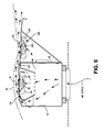
- FIG. 5 is a cross-sectional view of a single-side flotation IR step foil in accordance with certain embodiments
- FIGS. 6A-6D are schematic illustrations of various IR bar configurations in accordance with certain embodiments.
- FIG. 7 is a cross-sectional view of a Coanda air float bar having two IR light sources in accordance with certain embodiments
- FIG. 8A is a top view of an air bar showing an air flow adjustment mechanism in accordance with certain embodiments.
- FIG. 8B is a side view of an air bar showing an air flow adjustment mechanism in accordance with certain embodiments.
- FIG. 8C is a bottom view of an air bar showing an air flow adjustment mechanism in accordance with certain embodiments.
- FIG. 8D is an end cross-sectional view of an air bar showing an air flow adjustment mechanism in accordance with certain embodiments
- FIG. 9A is a top view of an air bar showing an air flow adjustment mechanism in accordance with certain embodiments.
- FIG. 9B is an end cross-sectional view of an air bar showing an air flow adjustment mechanism in accordance with certain embodiments.
- FIG. 10 is a schematic diagram of a dryer incorporating a plurality of IR float bars in conjunction with supply air, re-circulating air and exhaust air features in accordance with certain embodiments;
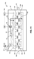
- FIG. 11 is a schematic diagram of the dryer of FIG. 10A depicting supply air, re-circulating air and exhaust air flow paths;
- FIG. 12 is a schematic diagram of a dryer incorporating a plurality of IR float bars in conjunction with supply air, re-circulating air and exhaust air features in accordance with certain embodiments.
- FIG. 13 is a schematic diagram of a dryer incorporating a plurality of IR float bars with controls in conjunction with supply air, re-circulating air and exhaust air features in accordance with certain embodiments.
- the float bars disclosed herein have one or more primary air jets which discharge from slots.
- the primary jets create a pressure field to floatingly support a web.
- the air supplied to the primary jets may be optionally heated to enhance heat and/or mass transfer for drying of the web.
- Air for cooling the emitter, reflector and lens elements contained in a removable channel may be taken from the same supply plenum as the primary flotation air, or alternately ducted from a separate air source to the channel assembly.
- the cooling air is discharged through one or more secondary jets which sweep the face of the planar lens and prevent contact of the web and solvent materials from the lens.
- FIGS. 1 and 2 show a preferred embodiment wherein the floater bar element 10 is of the Coanda type having two primary flotation jets; a first primary flotation slot 12 A and a second primary flotation slot 12 B.
- Two secondary air slots 14 A and 14 B that are preferably 5 to 40% of the primary slots 12 A, 12 B, most preferably 15 to 30% are also provided as shown.
- Supply air enters the supply plenum 15 of the air bar 10 via a supply air feed inlet 16 (e.g., a plurality of oval shaped apertures) located at the bottom 18 of the air bar 10 and is distributed along the length of the air bar to obtain suitable distribution to the flotation jets as is known in the art.
- a supply air feed inlet 16 e.g., a plurality of oval shaped apertures
- An infrared element is configured as a channel assembly comprised of a supporting channel 20 which contains a reflector 21 in fluid communication with the supply air plenum 15 , or a separate cooling air source as mentioned earlier, by means of one or more apertures 22 which penetrate the base channel and are in substantial alignment with comparable apertures 23 in the reflector 21 at the point of tangent contact with the base channel 20 .
- the total area of the apertures is preferably equivalent in flow area to 20 to 100% of the area of the primary flotation slots 12 A, 12 B, that is, slot length ⁇ slot width ⁇ number of slots.
- the active area of the apertures may be adjusted by aligning the array of apertures in the reflector 21 with a comparable array of apertures in the base channel 20 , ranging from full alignment to complete closure, thus acting as an adjustable damper for setting of the cooling air flow.
- Suitable mechanical means of sliding the reflector with respect to the base channel to achieve the desired alignment can easily be accomplished by those skilled in the art.
- FIGS. 8A-8D show preferred embodiments for the sliding and stationary elements in the channel assembly to enable the adjustment of the infrared emitter cooling air flow.
- FIGS. 8A and 8B show a sliding adjustment element 27 with circular apertures 22 a that can be aligned with corresponding preferably larger apertures 22 in the removable channel 20 .
- Corresponding oversized apertures are located in reflector element 21 such that these apertures coincide with the apertures 22 in removable channel 20 .
- Sliding adjustment element 27 has adjustment slots 27 a to allow the moveable element 27 to slide in position relative to reflector 21 and removable channel 20 such that the aperture 22 open area is reduced from the fully concentric alignment position.
- FIGS. 9A and 9B show a more preferred embodiment wherein apertures 22 a in the sliding adjustment element 27 and the apertures 22 in removable channel 20 are diamond shaped, thus allowing a finer adjustment of flow when moving the sliding adjustment element when reducing the aperture 22 flow area.
- Apertures 23 in the reflector 21 are oblong.
- the removable channel 20 includes a bottom member 40 that is supported on distribution member 24 , and opposite side members 41 A, 41 B that each terminate in inwardly facing terminal ends 11 A, 11 B.
- the outer surface of the chamber 20 transitioning between the sides 41 A, 41 B and the respective terminal ends 11 A, 11 B are curved so as to define, with the corresponding terminal ends of the sides 7 A, 7 B of the air bar 10 , Coanda slots, which are the primary flotation slots 12 A, 12 B.
- the removable channel 20 can be slidingly removed from the air bar 10 , along with its contents, and either be replaced by another channel, or by the same channel after maintenance or replacement of the lens and/or bulb contained therein.
- An initial air distribution member 19 such as a perforated plate, can be provided in the air bar 10 to enhance uniform supply air distribution.
- An open area of about 13% in such a member has been found to be suitable.
- a secondary air distribution member 24 such as plate perforated with slots or holes, can be positioned downstream of the initial air distribution member 19 as shown, and also can serve to support the removable channel 20 .
- the channel 20 contains an infrared light source 30 , such as an IR emitter bulb commercially available from Heraeus Noblelight GmbH.
- a lens 32 preferably a planar quartz lens, can be positioned above the IR light source 30 as shown. The lens encloses the emitter while allowing transmission of electromagnetic energy in the range of infrared wavelengths to pass through and reach the web 50 floating above the bar 10 ( FIG. 2 ). Electromagnetic energy emitted from the IR light source 30 passes through the lens 32 and directly radiates onto the web 50 .
- a reflector 21 is also contained in the channel 20 , and is preferably parabolic and made of a suitable reflective material such as stainless steel or aluminum.
- the reflector 21 extends from the lens downwardly below the IR light source, thereby surrounding the IR light source except in the area occupied by the lens, so that light emitted from the light source radiates either directly through the lens or is reflected by the reflector towards the lens, and is then ultimately radiated onto the web 50 , as shown diagrammatically in FIG. 2 .
- the secondary slots 14 A, 14 B are defined by the clearance (e.g., 0.0010′′ to 0.003′′) provided between the lens 32 and the inwardly facing terminal ends 11 A, 11 B of the chamber 20 .
- supply air fed into the air bar at inlet 16 flows through the perforated initial air distribution member 19 , through perforated secondary air distribution member 24 , out through primary flotation slots 12 A, 12 B where a pressure pad or field is created to floatingly support the web 50 .
- Supply air also passes through the cooling air entry jets in the member 24 , the bottom 40 of the channel 20 , and the reflector 21 , and flows in the area defined by the reflector 21 and the lens 32 .
- That air thus cools the emitter 30 , the reflector and the lens.
- the resulting heated air then flows out of the interior of the channel 20 through one of the secondary slots 14 A, 14 B, and sweeps the face of the lens 32 , thereby preventing contact of the web and solvent materials and other debris or contaminants with the lens 32 .
- the fluid for cooling the emitter, reflector and lens elements may be ducted from a separate air source to the channel assembly.
- the lens 32 can be omitted, and the air discharged from the channel assembly can be used as a virtual lens, effectively shielding the emitter 30 from the web and potentially hazardous debris or contaminants.
- FIG. 4 illustrates an embodiment wherein the float bar is a single-side flotation air foil 10 ′.
- a single primary flotation jet 12 ′ is provided to discharge supply air to float the web 50
- a single secondary jet 14 ′ is provided to discharge cooling air from the removable channel assembly 20 ′.
- the air foil 10 ′ is defined in part by a header, which in the embodiment shown, is generally rectangular in cross-section except for its top portion. Opposite sides 7 A′, 7 B′ of the header terminate in respective top flange portions 8 A′, 8 B′.
- Top flange portion 8 A′ is angled, preferably at about 65° relative to vertical, and terminates in a bent portion 13 ′.
- Top flange portion 8 B′ extends towards opposite side 7 A′ in a substantially horizontal fashion.
- the header defines an interior space 15 ′ that serves as a plenum for the gas that is received via the one or more holes (not shown) at the base of the air foil 10 ′ that are in gas-receiving communication with a gas supply (not shown).
- the header is positioned on suitable ducting by aligning the aligners 3 at each end plate of the header and is sealed by retainer gasket 4 .
- a diffuser plate having a plurality of spaced holes can be positioned in the header to help distribute the supply of gas evenly as it flows towards the slots.
- an optionally removable channel assembly 20 is provided, and contains a reflector 21 , a lens 32 , and an IR light source 30 .
- the cooling air (now heated) is discharged from the channel 20 via the clearance between the lens 32 and the flat port 23 .
- FIG. 5 illustrates an embodiment wherein the float bar is a single-side flotation step foil 10 ′′, such as that disclosed in U.S. Pat. No. 7,530,179, the disclosure of which is hereby incorporated by reference.
- an optionally removable channel assembly 20 can be provided that contains the reflector 21 , IR light source 30 and lens 32 .
- Differences between the embodiment of FIG. 5 and that of FIG. 4 include in the FIG. 5 embodiment the provision of a second secondary slot 14 B′, spaced from and stepped down from the primary slot 12 A, is to aid in floating the web 50 . Air discharged from the secondary discharge slot 14 B travels parallel to the web.
- Air discharged from the primary discharge slot 12 A is gathered into the air stream of the secondary discharge slot 14 B′ in a direction parallel to the web transport direction.
- a generally flat web support surface including the face of the lens 32 .
- a second web support surface Downstream of the secondary discharge slot, in the direction of web travel, is a second web support surface that comprises a wing portion that slopes downwardly as it extends away from the secondary discharge slot 14 B′.
- This second web support surface optionally can include a second lens 332 that forms part of an optional second channel assembly 200 comprising a reflector 221 , an IR light source 300 , and the lens 332 .
- the side 7 B of the stepfoil can include one or more apertures 60 to allow supply air (or air from another source) to enter the channel assembly and cool the components therein as above.
- FIG. 7 illustrates a further embodiment, in a Coanda nozzle having two Coanda discharge slots 12 A′′, 12 B′′.
- an IR light source 30 ′′ is positioned upstream, in the direction of web travel, of the first Coanda discharge slot 12 A.
- Bent member 8 A′′ that defined in part the Coanda discharge slot 12 A′′ includes one or more apertures that allow air to pass through and flow about the IR light source 30 ′′ to cool the same.
- a lens 32 ′′ can be positioned above the light source 30 ′′ that is transmissive to electromagnetic energy, and if provided, the lens is also cooled by the flow of air that cools the light source 30 ′′.
- the cooling air can function as a virtual lens, keeping the light source 30 ′′ cool and free of debris and contaminants.
- a second IR light source 30 A′′ can be positioned downstream, in the direct of web travel, of the second Coanda slot 12 B′′, arranged in a manner similar to the upstream assembly.
- the downstream assembly is shown without a lens, although one could be used as in the upstream assembly.
- FIGS. 6A-6D illustrate suitable arrangements of pluralities of infrared bars with respect to a traversing web 270 . It is noted that the air bars shown are illustrative only; any of the air bar embodiments disclosed herein (e.g., Coanda, air foil, step foil, etc. can be used). Other arrangements are also possible.
- FIG. 6A illustrates a plurality of infrared air bars 272 a - 272 n positioned below a traversing web 270 .
- FIG. 6B illustrates a plurality of infrared air bars 274 a - 274 n positioned above a traversing web 270 .
- FIG. 6C illustrates a plurality of infrared air bars 276 a - 276 n and a plurality of infrared air bars 278 a - 278 n in an opposing vertically aligned arrangement about a traversing web 270 for rapid drying of the traversing web 270 .
- FIG. 6D illustrates a plurality of infrared air bars 280 a - 280 n and a plurality of infrared air bars 282 a - 282 n arranged in alternating opposing vertical arrangement about a traversing web 270 creating a sinusoidal shape for the traversing web 270 .
- FIGS. 10-13 illustrate preferred embodiments of infrared air float bars arranged in a dryer enclosure 301 having a web 270 entering said enclosure through web slot 305 a and exiting through exit slot 305 b , said web floatingly traverses through a combined convection and infrared radiation heating zone created by infrared air bars which direct infrared energy to the web and handle distribution of heated supply air jets to impinge on the web.
- the enclosure 301 contains the spent heated air after fluid contact with the web such that collection of at least a portion of the spent air may be recovered for re-circulation to the air bars. At least a portion of the spent air is exhausted from the enclosure as described in the embodiments herein.
- FIG. 10 illustrates a dryer embodiment 300 a comprised of a plurality of infrared air bars 280 a - 280 n mounted to and in fluid communication with an air supply distribution header 310 a , and a plurality of infrared air bars 282 a - 282 n mounted to and in fluid communication with an air supply distribution header 310 b .
- Fluid communication between the plurality of infrared air bars 280 a - 280 n and 282 a - 282 n to each respective header 310 a and 310 b is made through feed openings 315 a - 315 n .
- the air feed openings 315 a - 315 n are connected and sealed to air bar feed inlet 16 ( FIG.
- FIG. 11 illustrates the air flow paths created by the air flow elements within the enclosure 301 of dryer 300 a of FIG. 10 herein described.
- a zone supply fan 320 collects heated air from inside the enclosure 301 and discharges said air under pressure into a plenum 322 having an optional heat source 325 .
- This heat source may be a fuel burner, a heat exchange coil from a heating media such a hot water, steam, or thermal oil, or preferably an electric element duct heater.
- a heating media such as a hot water, steam, or thermal oil
- the heated air is directed to air distribution headers 310 a and 310 b via ducts 326 a and 326 b , respectively.
- Optional heater 325 if provided, may be controlled by an air temperature control loop 340 .
- the heated air is then distributed to infrared air bars through feed openings 315 a - 315 n wherein it is used to cool the internal elements of the infrared air bars.
- the air flow paths and cooling function within each infrared air bar have been described previously.
- Electrical power fed to the emitters is regulated by an operator through a user interface in communication with an SCR according to the web drying load in order to achieve a satisfactorily dried product.
- the air comes into fluid contact with the web to convectively exchange heat and mass with the web 270 .
- this “spent” air is drawn back to the inlet of supply fan 320 .
- An amount of room air is drawn into enclosure 301 through web slots 305 a and 305 b .
- An exhaust flow balancing this room air and any evaporated solvents from the web must be continually ventilated out of the enclosure.
- a separate exhaust fan 331 draws at least a portion of said spent air through exhaust duct 332 and flow control damper 336 and discharges it to atmosphere.
- the exhaust flow rate could be controlled by a variable speed motor and drive connected to exhaust fan 331 instead of control damper 336 .
- the separate exhaust fan 331 of dryer embodiment 300 a is necessary for safely handling volatile flammable solvent materials and/or in the case a direct fired fuel burner is used for optional heater 325 .
- Exhaust flow safety ventilation volume and treatment equipment (not shown) for air polluting materials in said exhaust may be required based on requirements set forth by parties having such jurisdiction as will be understood by those familiar with such regulations in their locale.
- FIG. 12 illustrates a preferred dryer embodiment 300 b for drying a non-flammable solvent, such as water, wherein supplemental heat beyond that provided by the infrared air bars is not needed to meet the thermal load required by the web.
- a non-flammable solvent such as water
- FIG. 12 illustrates a preferred dryer embodiment 300 b for drying a non-flammable solvent, such as water, wherein supplemental heat beyond that provided by the infrared air bars is not needed to meet the thermal load required by the web.
- a non-flammable solvent such as water
- non-infrared air bars may be of a number of types which are familiar to those skilled in the art of air bar design.
- the non-infrared air bars are preferentially located near the web exit end of the dryer, and in the case of a single-side coating on the web, located on the uncoated side.
- Electrical power fed to the emitters is regulated by an operator through a user interface in communication with an SCR according to the web drying load in order to achieve a satisfactorily dried product.
- the supply air temperature is regulated by control loop 340 to maintain a set point by modulating the amount of exhaust through exhaust duct 330 by means of damper 335 .
- FIG. 13 illustrates a preferred embodiment for a single-side coated or printed web wherein the ink or coating is on the bottom side of the web.
- Electrical power fed to emitters 282 a - 282 n is regulated by an operator through a user interface in communication with an SCR 342 according to the web drying load in order to achieve a satisfactorily dried product.
- the air temperature is controlled through control loop 340 a which regulates the power setting to SCR 341 which in turn modulates the power to the emitters in infrared air bars 280 a - 280 n facing the uncoated side of the web.
- a plurality of infrared electromagnetic energy rays increase drying capacity because the infrared source is located at the point of highest heat transfer, e.g., between the discharge slots and radiate from the infrared source 32 either directly or indirectly through the lens 32 .
- the infrared drying energy is transmitted for heating a traversing web being processed in a dryer.
- a portion of the infrared rays reflect off the parabolic reflector 21 and through the lens 32 to impart infrared drying energy upon and heating the web.
- the wave length of the infrared electromagnetic rays emitted from the infrared source 32 can be short wave with a wave length of 0.78 to 1.2 microns, medium wave length with a wave length of 1.2 to 4.0 microns or long wave length of 4.0 to at least 10 or more microns.
- the infrared source 32 is positioned at a point of maximum energy transfer.
- Pressurized air to float the web enters the infrared air bar through the plurality of oval shaped air inlets 16 to float the web. From the air inlets, the pressurized air proceeds as indicated by dashed arrow lines ( FIG. 3 ) through the holes of the initial air distribution member 19 , through the holes of the secondary air distribution member 24 , through the Coanda slots 12 A and 12 B, along the Coanda curves defined by the side members 41 A, 41 B of the channel assembly 20 , and then inwardly along the upper surface of the lens 32 and upwardly, thus providing float lift for the web 50 and also carrying away solvent vapors in the web. Air also flows into the channel 20 and around the elements disposed therein to cool the same, and then ultimately leaks out through the clearance between the lens 32 and the side members 41 A, 41 B and sweeps over the outer face of the lens 32 .
- Direct and indirect infrared energy rays impinge on the web 50 and heat the web as it passes over the pressure pad created by the Coanda slots, thus drying and evaporating solvents from the web. This, in combination with impinging flow of air, maximizes the heat transfer in the area of the pressure pad.
- Output of the infrared source 30 can be variably controlled, such as by an SCR so that the amount of energy output transmitted from the infrared source includes a range from full power to no power, and any variable range therebetween.
- Embodiments disclosed herein provide an air float bar with at least one primary air jet for flotation flow and heat transfer to the web and at least one integrated infrared emitter for use in the drying or heat treatment of webs, so as to maximize the utilization of infrared energy to heat and/or dry the web when in combination with at least one secondary air jet.
- the at least one secondary air jet is supplied by about 5 to 40% of the total air (preferably 7 to 15%) which is first heated by passing in fluid contact with at least one infrared emitter and is preferably also guided in fluid contact with a reflector, and further guided in fluid contact with a lens that is transmissible to infrared energy.
- the secondary jet is guided in fluid contact in a substantially parallel flow direction to the lens surfaces and provides at least a portion of the flotation air in conjunction with the at least one primary air jet, the parallel flow providing sufficient cooling to the emitter, reflector and lens elements to prevent ignition of combustible web or coating materials even under upset conditions.
- An optimum amount of cooling air is guided in contact with the emitter, reflector and lens surfaces to promote effective cooling of the emitter, reflector and lens, and further the cooling air is guided after contacting and gaining heat from said surfaces to deliver mass flow and thermal energy to the web by convection.
- the cooling air is also guided over the surfaces to prevent contact of the solvent-laden air inside the drying enclosure from contacting said surfaces, thus preventing their contamination.
- the combined convection and radiation heat transfer modes of the present invention are driven substantially independently by virtue of the convection air temperature and emitter temperature, respectively.
- This feature can be used to advantage in the embodiments disclosed herein for the purpose of rapidly drying high moisture areas without excessively heating low moisture areas. Such disparities in moisture across a web are common in printing where heavy ink images are present alongside of low coverage or unprinted areas.
- the embodiments disclosed herein provide a selectivity in heating wet areas in that the heavy print areas require large heat flux to dry quickly and remain at or near the wet bulb temperature due to the evaporative cooling effect, thus these areas will be substantially heated by both the radiation and the high velocity convection modes provided by this infrared floatation air bar.
- those areas having little or no coverage will tend to increase in temperature by the infrared radiation from the emitters, but near the exit of the dryer can be cooled by the convection air to avoid overheating.
- the electromagnetic energy from the infrared elements is emitted at a relatively high temperature (typically >2000° F.) compared to the web temperature (typically 150 to 300° F.).
- the emissive heat flux to the web changes relatively little as the web temperature increases because the emitter temperature is quite high and the emitter temperature dominates the radiation flux potential according to the forth power of absolute temperature.
- the heat transfer by convection is driven by a linear potential between air temperature and web temperature.
- the maximum web temperature for a given web material being thermally processed is often limited during the drying operation in order to avoid quality defects in the web or coating.
- ink or coating materials When ink or coating materials are overheated beyond their maximum thermal rating as specified by the manufacturer, they may degrade in function and appearance often becoming discolored, brittle or chalky.
- the web substrate materials are overheated beyond their maximum thermal rating as specified by the manufacturer they may degrade in mechanical performance as well as appearance, often becoming discolored, brittle or distorted.
- polymer web materials such as PET may soften and stretch causing distortion of the initially planar web resulting in waves or cockling, especially at temperatures exceeding 200° F.
- Paper webs may exhibit similar out-of-plane distortion due to hygroscopic shrinkage of over-dried areas having less than 3% moisture in proximity to heavy coated or printed areas having moisture levels several percent higher than the adjoining areas. Paperboard tends to curl if the moisture on one side is reduced to levels several percent lower than the opposite side. Additionally, paper and paperboard material will tend to brown and become brittle at temperatures in the range of 350 to 400° F., and eventually burn at higher temperatures. In order to avoid these problems, printers and converters of web materials will be familiar with the maximum temperature limitations for processing of the web and coating through specifications provided by the suppliers of the materials, or from pilot drying trials, or by experience with same or similar materials in prior production processing.
- air temperature set point is selected at a temperature just below the maximum web temperature to be tolerated in the hottest (driest) areas of the web, the infrared heating in these areas will be countered by convective cooling, thus mitigating excessive temperature in said driest areas.
- Air temperature set points from 10 to 50 Fahrenheit degrees below the maximum web temperature to be tolerated were found to be effective in avoiding overheating of the web.
- the air temperature may be selected and regulated to be typically in the range of 30 to 100 Fahrenheit degrees above the wet bulb temperature in the dryer (wet bulb typically ⁇ 180° F.) the convective flux potential is diminished and even reversed, thus slowing the rate of heating of the web in the driest areas once the web temperature in those areas exceeds the air temperature.
- the convection coefficient provided by the infrared air bars must be suitably high, exceeding that of conventional cooling air systems employed in non-flotation infrared dryers.
- Suitable air bar heat convection heat transfer coefficients are in the range of about 10 to about 40 BTU/hr-ft 2 -F.
- Suitable air bar slot jet velocities are in the range of from about 5000 to about 16000 feet per minute.
- the air temperature supplied to the nozzles may be regulated by adding a controlled input of heat from an independent heat source such as an electric resistance coil, hot oil or steam coil, or a burner located in the ducting supplying the air to bars.
- an independent heat source such as an electric resistance coil, hot oil or steam coil, or a burner located in the ducting supplying the air to bars.
- the need for an independent source of heat is obviated by recovering the heat from the emitters that is not absorbed by the radiation mode into the web into the re-circulated air.
- This heat recovered in the re-circulation air may be retained by minimizing the amount of air exhausted to about 10% or less of the air bar supply air thus maximizing the re-circulating air temperature.
- the amount of exhaust may be increased to about 30% or more thus drawing in more ambient air that must be heated in the re-circulating flow.
- the air temperature may be regulated by modulating the input power to at least one infrared emitter through a closed-loop controller.
- the primary regulation of the air temperature is made by setting the dryer exhaust to achieve a desired temperature as previously mentioned, and further controlled by regulating the power to at least one emitter with a closed-loop controller which regulates the set point for the power output of an SCR supplying power to the at least one emitter.
- a printed paper web with a water-based ink is to be dried.
- the expected wet bulb temperature is 135° F. and the convection air temperature is set to 170° F.
- the net radiative heat flux from the emitters to the unprinted web is 6,500 BTU/hr-ft 2 and the convection coefficient per side is 25 BTU/hr-ft 2 -F.
- the initial combined convection and radiation heating rate is 11,500 BTU/hr-ft 2 and the terminal temperature of the web, where radiation flux is offset by convection cooling in the unprinted areas of the web, will be ⁇ 300° F.
- the initial heating rate is only 6,500 BTU/hr-ft 2 resulting in slower heating, and the calculated terminal temperature is over 800° F., well above the ignition point of paper.
- the infrared air bars are placed 8 to 20 inches apart on each side of the web, with nozzle air jet velocities in the range of 5000 to 16,000 fpm, with the total emitter heat flux per emitter element mounted in each air bar in the range of 100 to 200 watts per inch for medium wave carbon emitters, and 200 to 400 watts per inch for near IR emitters.
- Air temperature set points in the range of 150 to 250° F. are preferred for water based coatings on paper substrates.
Abstract
Description
Claims (11)
Priority Applications (4)
| Application Number | Priority Date | Filing Date | Title |
|---|---|---|---|
| US12/792,294 US9228779B2 (en) | 2009-06-05 | 2010-06-02 | Infrared float bar |
| US13/676,508 US10139159B2 (en) | 2009-06-05 | 2012-11-14 | Infrared float bar |
| US13/890,582 US9746235B2 (en) | 2009-06-05 | 2013-05-09 | Infrared float bar |
| US14/263,059 US10371443B2 (en) | 2009-06-05 | 2014-04-28 | Infrared float bar |
Applications Claiming Priority (2)
| Application Number | Priority Date | Filing Date | Title |
|---|---|---|---|
| US18435309P | 2009-06-05 | 2009-06-05 | |
| US12/792,294 US9228779B2 (en) | 2009-06-05 | 2010-06-02 | Infrared float bar |
Related Child Applications (3)
| Application Number | Title | Priority Date | Filing Date |
|---|---|---|---|
| US13/676,508 Division US10139159B2 (en) | 2009-06-05 | 2012-11-14 | Infrared float bar |
| US13/890,582 Division US9746235B2 (en) | 2009-06-05 | 2013-05-09 | Infrared float bar |
| US14/263,059 Division US10371443B2 (en) | 2009-06-05 | 2014-04-28 | Infrared float bar |
Publications (2)
| Publication Number | Publication Date |
|---|---|
| US20110131829A1 US20110131829A1 (en) | 2011-06-09 |
| US9228779B2 true US9228779B2 (en) | 2016-01-05 |
Family
ID=43298112
Family Applications (4)
| Application Number | Title | Priority Date | Filing Date |
|---|---|---|---|
| US12/792,294 Active 2031-08-05 US9228779B2 (en) | 2009-06-05 | 2010-06-02 | Infrared float bar |
| US13/676,508 Active US10139159B2 (en) | 2009-06-05 | 2012-11-14 | Infrared float bar |
| US13/890,582 Active 2032-05-28 US9746235B2 (en) | 2009-06-05 | 2013-05-09 | Infrared float bar |
| US14/263,059 Active US10371443B2 (en) | 2009-06-05 | 2014-04-28 | Infrared float bar |
Family Applications After (3)
| Application Number | Title | Priority Date | Filing Date |
|---|---|---|---|
| US13/676,508 Active US10139159B2 (en) | 2009-06-05 | 2012-11-14 | Infrared float bar |
| US13/890,582 Active 2032-05-28 US9746235B2 (en) | 2009-06-05 | 2013-05-09 | Infrared float bar |
| US14/263,059 Active US10371443B2 (en) | 2009-06-05 | 2014-04-28 | Infrared float bar |
Country Status (8)
| Country | Link |
|---|---|
| US (4) | US9228779B2 (en) |
| EP (4) | EP2437941B1 (en) |
| JP (6) | JP5670443B2 (en) |
| AU (1) | AU2010256680B2 (en) |
| CA (5) | CA3172541A1 (en) |
| ES (4) | ES2538257T3 (en) |
| TW (1) | TW201102599A (en) |
| WO (1) | WO2010141587A1 (en) |
Cited By (2)
| Publication number | Priority date | Publication date | Assignee | Title |
|---|---|---|---|---|
| US9746235B2 (en) | 2009-06-05 | 2017-08-29 | Megtec Systems, Inc. | Infrared float bar |
| CN113262170A (en) * | 2021-05-18 | 2021-08-17 | 孙德忠 | Intelligent processing equipment and processing method for flaky medicine |
Families Citing this family (30)
| Publication number | Priority date | Publication date | Assignee | Title |
|---|---|---|---|---|
| GB0515749D0 (en) | 2005-07-30 | 2005-09-07 | Dyson Technology Ltd | Drying apparatus |
| GB0515754D0 (en) | 2005-07-30 | 2005-09-07 | Dyson Technology Ltd | Drying apparatus |
| GB2428569B (en) | 2005-07-30 | 2009-04-29 | Dyson Technology Ltd | Dryer |
| GB0515750D0 (en) | 2005-07-30 | 2005-09-07 | Dyson Technology Ltd | Drying apparatus |
| GB2434094A (en) | 2006-01-12 | 2007-07-18 | Dyson Technology Ltd | Drying apparatus with sound-absorbing material |
| WO2009147871A1 (en) * | 2008-06-02 | 2009-12-10 | 東京エレクトロン株式会社 | Fluid heater, manufacturing method thereof, substrate processing device equipped with a fluid heater, and substrate processing method |
| US9068775B2 (en) | 2009-02-09 | 2015-06-30 | Heat Technologies, Inc. | Ultrasonic drying system and method |
| US10401085B2 (en) | 2010-09-10 | 2019-09-03 | Durr Megtec, Llc | Air bar arrangement for drying tissue on a belt |
| JP5772382B2 (en) * | 2011-08-16 | 2015-09-02 | セイコーエプソン株式会社 | Recording device |
| US8756830B2 (en) * | 2012-10-11 | 2014-06-24 | Eastman Kodak Company | Dryer transporting moistened medium through heating liquid |
| DE102013104577B3 (en) * | 2013-05-03 | 2014-07-24 | Heraeus Noblelight Gmbh | Apparatus for drying and sintering metal-containing ink on a substrate |
| US20140352561A1 (en) * | 2013-05-31 | 2014-12-04 | Joe I.V. Rosenberg | Process and apparatus for conversion of a coldset web printing press to a hybrid heatset and coldset printing press |
| EP3105060B1 (en) | 2014-02-13 | 2020-04-08 | Brown Manufacturing Group, Inc. | Ink curing apparatus and method |
| US10179468B2 (en) | 2014-03-14 | 2019-01-15 | Hewlett-Packard Development Company, L.P. | Drying media |
| US10488108B2 (en) * | 2014-07-01 | 2019-11-26 | Heat Technologies, Inc. | Indirect acoustic drying system and method |
| WO2016014960A1 (en) | 2014-07-24 | 2016-01-28 | Heat Technologies, Inc. | Acoustic-assisted heat and mass transfer device |
| JP6269373B2 (en) * | 2014-07-29 | 2018-01-31 | 日立金属株式会社 | Manufacturing method and manufacturing apparatus for enameled wire |
| US10327605B2 (en) * | 2014-12-18 | 2019-06-25 | Durr Megtec, Llc | Air bar cleaning tool, system and method |
| MX2018009654A (en) * | 2016-02-08 | 2019-01-31 | Egg Chick Automated Tech | Apparatus and method to detect upside down eggs. |
| WO2017169784A1 (en) | 2016-03-28 | 2017-10-05 | 日本碍子株式会社 | Low-temperature drying apparatus |
| KR102146530B1 (en) * | 2016-10-24 | 2020-08-20 | 주식회사 엘지화학 | Dryer |
| KR102257318B1 (en) | 2017-01-25 | 2021-05-27 | 가부시키가이샤 씽크. 라보라토리 | Surface drying device, printing device, and printing method of sheet-like non-penetrating substrate |
| US10723119B2 (en) * | 2017-03-17 | 2020-07-28 | Ricoh Company, Ltd. | Dryer, printer, and treatment liquid applicator |
| DE102017129017A1 (en) * | 2017-12-06 | 2019-06-06 | Heraeus Noblelight Gmbh | Method for drying a substrate, dryer module for carrying out the method and drying system |
| WO2019212494A1 (en) * | 2018-04-30 | 2019-11-07 | Kimberly-Clark Worldwide, Inc. | Air dryer utilizing low temperature, high velocity air |
| US11345166B2 (en) | 2018-08-31 | 2022-05-31 | Hewlett-Packard Development Company, L.P. | Power allocation in printing devices |
| CN110370798B (en) * | 2019-08-19 | 2020-11-13 | 浙江聚众柔印科技有限公司 | Pressure temperature control device for printing drying equipment |
| CN211186916U (en) * | 2019-10-14 | 2020-08-07 | 中山智淘电器制造有限责任公司 | Far infrared heating device and electric barbecue oven with same |
| WO2022049470A1 (en) * | 2020-09-02 | 2022-03-10 | 3M Innovative Properties Company | Heated air nozzle |
| KR102341360B1 (en) * | 2020-12-01 | 2021-12-21 | 천병용 | Apparatus for filament levitation and manufacturing method for bio filament using the same |
Citations (109)
| Publication number | Priority date | Publication date | Assignee | Title |
|---|---|---|---|---|
| GB636767A (en) | 1947-08-25 | 1950-05-03 | Bernard Offen | Apparatus for drying webs |
| US3040807A (en) | 1959-11-04 | 1962-06-26 | Industrial Nucleonics Corp | Moisture balance correction system |
| US3384282A (en) | 1964-09-03 | 1968-05-21 | Vits G M B H Maschf | Pneumatic conveyor for strip materials |
| US3460265A (en) | 1967-02-14 | 1969-08-12 | Horace L Smith Jr | Methods of drying |
| US3499232A (en) | 1967-11-13 | 1970-03-10 | Eduard J Zimmermann | Dryer having removable heating units |
| US3549070A (en) | 1969-02-27 | 1970-12-22 | Tec Systems | Floatation of sheet materials |
| US3587177A (en) | 1969-04-21 | 1971-06-28 | Overly Inc | Airfoil nozzle |
| US3590495A (en) | 1969-05-02 | 1971-07-06 | Goodyear Tire & Rubber | Dryer or heater with shielding means |
| US3640219A (en) | 1969-08-04 | 1972-02-08 | Burroughs Corp | Method of dry preparation of relief printing plates |
| US3643342A (en) | 1969-05-02 | 1972-02-22 | Goodyear Tire & Rubber | Dryer or heater with shielding means |
| US3675336A (en) | 1969-07-17 | 1972-07-11 | Weyerhaeuser Co | Method for drying wood |
| US3705676A (en) | 1970-03-16 | 1972-12-12 | Overly Inc | Air foil conveyor |
| SE352121B (en) | 1971-06-01 | 1972-12-18 | Polytype Ag | |
| US3720002A (en) | 1970-03-19 | 1973-03-13 | Wiggins Teape Res Dev | Drying sheet material |
| US3733461A (en) | 1971-05-26 | 1973-05-15 | Powell R | Radiant heater |
| US3763571A (en) | 1970-04-27 | 1973-10-09 | Vits Maschinenbau Gmbh | Apparatus for contactless guiding of webs |
| US3791049A (en) | 1971-10-04 | 1974-02-12 | Smitherm Industries | Drying methods with moisture profile control |
| US3807056A (en) | 1970-12-04 | 1974-04-30 | Polytype Ag | Device for the contact-free support of a web of material |
| US3815254A (en) | 1972-01-18 | 1974-06-11 | W Mills | Method and apparatus for controlling the amount of moisture removed from material |
| US3850224A (en) | 1973-07-30 | 1974-11-26 | Sherwood Refractories | Process and apparatus for drying shell molds |
| US3873013A (en) | 1973-10-04 | 1975-03-25 | Tec Systems | High velocity web floating air bar having center exhaust means |
| DE2351280A1 (en) | 1973-10-12 | 1975-05-15 | Buettner Schilde Haas Ag | IMPACT JET DRYER FOR RAIL-SHAPED GOODS |
| US3950650A (en) | 1974-03-25 | 1976-04-13 | Thermogenics Of New York, Inc. | Ink curing and drying apparatus |
| US4015340A (en) | 1975-08-20 | 1977-04-05 | Tec Systems, Inc. | Ultraviolet drying apparatus |
| US4021931A (en) | 1975-11-21 | 1977-05-10 | Midland-Ross Corporation | Air circulating apparatus for floating material in web form |
| SU566099A2 (en) | 1973-12-24 | 1977-07-25 | Барнаульский Научно-Исследовательский Институт Текстильной Промышленности | Plant for drying lengthy materials |
| US4074841A (en) * | 1975-12-15 | 1978-02-21 | Carl Kramer | Method and apparatus for floatation conveyance of strip materials |
| US4146974A (en) | 1977-09-19 | 1979-04-03 | Pray Robert W | Drying apparatus |
| US4197971A (en) | 1978-10-12 | 1980-04-15 | W. R. Grace & Co. | High velocity web floating air bar having an internal passage for transverse air discharge slot means |
| US4197973A (en) | 1978-10-12 | 1980-04-15 | W. R. Grace & Co. | High velocity web floating air bar having air flow straightening means for air discharge slot means |
| US4201323A (en) | 1978-10-12 | 1980-05-06 | W. R. Grace & Co. | High velocity web floating air bar having a recessed Coanda plate |
| US4265384A (en) | 1980-01-21 | 1981-05-05 | W. R. Grace & Co. | Air bar having asymmetrical inlet |
| US4290210A (en) | 1978-12-06 | 1981-09-22 | Ab Svenska Flaktfabriken | Device for drying web material |
| US4297583A (en) | 1979-02-08 | 1981-10-27 | American Can Company | Ultraviolet light apparatus |
| US4308984A (en) | 1978-05-11 | 1982-01-05 | Vits Maschinenbau Gmbh | Jet-conveyor box for floatingly guiding a conveyed strip or sheet material |
| US4336279A (en) | 1978-07-04 | 1982-06-22 | Metzger Wesley A | Apparatus and process for drying and curing coated substrates |
| US4359826A (en) | 1980-03-21 | 1982-11-23 | The Mead Corporation | Drying system |
| SE8303172L (en) | 1982-06-07 | 1983-12-08 | Impact Systems Inc | DEVICE FOR DRYING A RANGE OF MOVEMENT |
| US4425719A (en) | 1982-03-15 | 1984-01-17 | W. R. Grace & Co. | Compact air bar assembly for contactless web support |
| US4434562A (en) * | 1981-09-02 | 1984-03-06 | American Screen Printing Equipment Company | Curing apparatus and method |
| US4494316A (en) * | 1983-03-14 | 1985-01-22 | Impact Systems, Inc. | Apparatus for drying a moving web |
| US4501072A (en) | 1983-07-11 | 1985-02-26 | Amjo, Inc. | Dryer and printed material and the like |
| US4506454A (en) | 1981-06-10 | 1985-03-26 | Kerschgens Johann Josef | Appliance for the treatment of hair and scalp |
| US4513516A (en) | 1982-09-08 | 1985-04-30 | Bjoernberg Thomas | Method of and apparatus for the heat-treatment of a continuous web |
| US4514913A (en) | 1984-02-07 | 1985-05-07 | Impact Systems, Inc. | Apparatus for drying a moving web having movable dryer modules |
| US4575952A (en) | 1981-09-18 | 1986-03-18 | M.E.G., S.A. | Hot air dryer structure |
| US4590685A (en) | 1984-11-09 | 1986-05-27 | Roth Reinhold C | Method & apparatus for uniformly drying paper webs and the like |
| US4594795A (en) | 1984-10-23 | 1986-06-17 | Erik Stephansen | Air bearing support apparatus for drying a moving web |
| US4606137A (en) * | 1985-03-28 | 1986-08-19 | Thermo Electron Web Systems, Inc. | Web dryer with control of air infiltration |
| US4615122A (en) | 1984-04-09 | 1986-10-07 | Kimberly-Clark Corporation | Method for providing steam and hot air for hooded drying cylinders |
| US4638571A (en) | 1986-04-02 | 1987-01-27 | Cook William A | Radio frequency nozzle bar dryer |
| JPS62102899A (en) | 1985-10-30 | 1987-05-13 | Ebara Infilco Co Ltd | Drying method for organic sludge |
| US4674197A (en) | 1982-02-19 | 1987-06-23 | Vepa Aktiengesellschaft | Heat treatment tunnel |
| WO1987004739A1 (en) | 1986-02-06 | 1987-08-13 | Itronic Process Ab | Arrangement for a process plant arranged for the heat treatment of strip-shaped products |
| US4693013A (en) | 1985-06-25 | 1987-09-15 | A. Monforts Gmbh & Co. | Infrared dryer |
| US4698767A (en) | 1985-08-14 | 1987-10-06 | Electro Sprayer Systems, Inc. | Apparatus and method for controlling infrared dryer for discreet articles |
| US4727655A (en) | 1987-02-02 | 1988-03-01 | Amjo Infra Red Dryers, Inc. | Heat lamp assembly with air duct |
| US4756091A (en) | 1987-06-25 | 1988-07-12 | Herbert Van Denend | Hybrid high-velocity heated air/infra-red drying oven |
| US4773167A (en) | 1986-05-19 | 1988-09-27 | Amjo Infra Red Dryers, Inc. | Heater |
| US4776107A (en) | 1987-10-30 | 1988-10-11 | Wolverine Corporation | Web treatment system |
| JPS63502909A (en) | 1986-02-06 | 1988-10-27 | イントロニック プロセス アクチェボラーク | Heat treatment equipment used for heat treatment of strip products |
| US4785986A (en) | 1987-06-11 | 1988-11-22 | Advance Systems, Inc. | Paper web handling apparatus having improved air bar with dimensional optimization |
| US4809608A (en) | 1987-11-03 | 1989-03-07 | Kenneth Wolnick | Infrared dryer for printing presses |
| US4854052A (en) * | 1986-03-14 | 1989-08-08 | Valmet Oy | Floater radiation dryer |
| JPH0226742A (en) | 1988-06-07 | 1990-01-29 | W R Grace & Co | Air floating bar |
| US4901449A (en) | 1988-06-07 | 1990-02-20 | W. R. Grace & Co.-Conn. | Tri-flotation air bar |
| US4918828A (en) | 1987-11-02 | 1990-04-24 | Valmet Paper Machinery Inc. | Method and apparatus for drying a moving web |
| US4932140A (en) | 1987-09-28 | 1990-06-12 | Valmet Paper Machinery Inc. | Arrangement of pressure nozzles for the treatment of webs |
| US4936025A (en) | 1988-04-25 | 1990-06-26 | Valmet Paper Machinery Inc. | Combination infrared and airborne drying of a web |
| US4942674A (en) | 1987-06-04 | 1990-07-24 | Valmet Paper Machinery Inc. | Method in the drying of a paper web or equivalent |
| US4952145A (en) | 1988-04-07 | 1990-08-28 | Vits Maschinenbau Gmbh | Apparatus for the heat treatment and/or drying of a web of material passing continuously through |
| US5009016A (en) | 1987-11-26 | 1991-04-23 | Valmet Oy | Method for on-machine coating-drying of a paper web or the like |
| US5010659A (en) | 1989-09-08 | 1991-04-30 | W. R. Grace & Co.-Conn. | Infrared drying system |
| US5035066A (en) | 1988-06-07 | 1991-07-30 | W. R. Grace & Co.-Conn. | Ultraviolet air floatation bar |
| US5060572A (en) | 1989-01-25 | 1991-10-29 | Baldwin-Gegenheimer Gmbh | Continuous drier on rotary offset printing presses and operation of such a drier during the printing and cylinder washing processes with the web running |
| USD323571S (en) | 1988-10-27 | 1992-01-28 | W. R. Grace & Co.-Conn. | Dryer for graphic arts |
| US5099586A (en) | 1989-09-08 | 1992-03-31 | W. R. Grace & Co.-Conn. | Reflector assembly for heating a substrate |
| US5125170A (en) * | 1990-04-11 | 1992-06-30 | Worldwide Converting Machinery | Flotation dryer nozzle |
| US5249373A (en) | 1991-01-29 | 1993-10-05 | W. R. Grace & Co.-Conn. | Web threading system |
| US5261166A (en) | 1991-10-24 | 1993-11-16 | W.R. Grace & Co.-Conn. | Combination infrared and air flotation dryer |
| US5272819A (en) | 1991-05-16 | 1993-12-28 | W. R. Grace & Co.-Conn. | Moveable web slot |
| US5377428A (en) | 1993-09-14 | 1995-01-03 | James River Corporation Of Virginia | Temperature sensing dryer profile control |
| US5395029A (en) * | 1989-12-29 | 1995-03-07 | Somerset Technologies, Inc. | Flotation nozzle for web handling equipment |
| US5440821A (en) | 1991-04-22 | 1995-08-15 | Infrarodteknik Ab | Method and a device of treating a continuous material web with infrared light and heated air |
| US5443539A (en) * | 1994-09-08 | 1995-08-22 | Westelaken; Christianus M. T. | Particulate dryer |
| WO1996018074A1 (en) | 1994-12-06 | 1996-06-13 | W.R. Grace & Co.-Conn. | Combination air bar and hole bar flotation dryer |
| US5537925A (en) | 1993-09-03 | 1996-07-23 | Howard W. DeMoore | Infra-red forced air dryer and extractor |
| US5638611A (en) | 1995-10-18 | 1997-06-17 | Voith Sulzer Papiermaschinen Gmbh | Single-tier drying section tailored for compensating stretching and shrinking of paper web |
| US5694702A (en) | 1997-01-06 | 1997-12-09 | International Paper Company | Enhancing cross-directional stretch and tensile energy absorption during paper manufacture |
| US5737851A (en) | 1996-03-01 | 1998-04-14 | Congoleum Corporation | Thermal processing unit for the preparation of plastisol-based floor coverings |
| US5765294A (en) | 1995-12-12 | 1998-06-16 | Koenig & Bauer-Albert Aktiengesellschaft | Method and apparatus for feeding and drying a printed paper web |
| US5797327A (en) | 1996-02-28 | 1998-08-25 | Heidelberger Druckmaschinen Ag | Device and method for guiding sheet material in a printing press, particulary in a sheet-fed rotary offset press |
| US5813134A (en) | 1995-10-06 | 1998-09-29 | Avery Dennison Corporation | Apparatus and method for drying or curing web materials and coatings |
| US5829166A (en) * | 1996-05-15 | 1998-11-03 | Vits Maschinenbau Gmbh | Air-cushion nozzle for drying apparatus |
| US5867920A (en) | 1997-02-05 | 1999-02-09 | Megtec Systems, Inc. | High speed infrared/convection dryer |
| US6049995A (en) | 1999-04-20 | 2000-04-18 | Megtec Systems, Inc. | Infrared dryer with air purge shutter |
| US6262431B1 (en) | 1997-10-27 | 2001-07-17 | Heraeus Noblelight Gmbh | Infrared spheroidal radiation emitter |
| US6325896B1 (en) | 1999-09-23 | 2001-12-04 | Valmet-Karlstad Ab | Apparatus for transferring a fast running fibrous web from a first location to a second location |
| US20010053646A1 (en) | 2000-03-16 | 2001-12-20 | Kuraray Co., Ltd. | Hollow fibers and manufacturing method of hollow fibers |
| WO2002016139A1 (en) | 2000-08-25 | 2002-02-28 | Howard Demoore | Power saving automatic zoned dryer apparatus and method |
| US20030110659A1 (en) | 2000-05-18 | 2003-06-19 | Wolfgang Mohr | Dryer device |
| US6598315B1 (en) | 1999-06-30 | 2003-07-29 | Metso Paper, Inc. | Nozzle arrangement in airborne web-drying and method for improving heat transfer in airborne web-drying |
| US20030177927A1 (en) | 2002-03-22 | 2003-09-25 | Oxy-Dry Corporation | Printing press with infrared dryer safety system |
| US20050223593A1 (en) | 2004-04-13 | 2005-10-13 | Rocheleau Michael O | Step air foil |
| JP2006223980A (en) | 2005-02-17 | 2006-08-31 | Yamato Sanko Seisakusho:Kk | Steam-jet spraying device and thickening crushing dryer using it |
| EP1777069A2 (en) | 2005-10-18 | 2007-04-25 | Mitsubishi Heavy Industries, Ltd. | Water-based-varnish drying apparatus and printing press |
| JP2007120777A (en) | 2005-10-25 | 2007-05-17 | Sumitomo Metal Mining Co Ltd | Drying storage method of resin film for two-layer flexible substrate, and heating dryer |
| JP2007240066A (en) | 2006-03-08 | 2007-09-20 | Shibamura Netsuriyo Kaihatsu:Kk | Water cooler, water cooling type dehumidifier, and drying machine |
| US20130104414A1 (en) | 2009-06-05 | 2013-05-02 | Megtec Systems, Inc. | Infrared Float Bar |
Family Cites Families (11)
| Publication number | Priority date | Publication date | Assignee | Title |
|---|---|---|---|---|
| US4188731A (en) | 1976-08-25 | 1980-02-19 | Rauskolb Fred W | Method and apparatus for eliminating wet streaks in fibrous sheets or webs by infra-red radiation |
| US5156312A (en) | 1989-12-29 | 1992-10-20 | Somerset Technologies, Inc. | Flotation nozzle for web handling equipment |
| US5462746A (en) * | 1992-11-02 | 1995-10-31 | Lts Lohmann Therapie-Systeme Gmbh & Co. Kg | Patch for transdermal administration of volatile pharmaceutically active ingredients of chemically basic nature and a process for preparation |
| GB9323954D0 (en) | 1993-11-19 | 1994-01-05 | Spooner Ind Ltd | Improvements relating to web drying |
| US5568693A (en) | 1994-09-05 | 1996-10-29 | Agfa-Gevaert N.V. | Method and an apparatus for the processing of photographic sheet material |
| US6210705B1 (en) * | 1997-12-15 | 2001-04-03 | Noven Pharmaceuticals, Nc. | Compositions and methods for treatment of attention deficit disorder and attention deficit/hyperactivity disorder with methylphenidate |
| US6095047A (en) | 1998-07-13 | 2000-08-01 | Heidelberger Drukmaschinen Ag | Web-fed rotary printing press with apparatus for diverting a wet printed web |
| US20030170195A1 (en) * | 2000-01-10 | 2003-09-11 | Noven Pharmaceuticals, Inc. | Compositions and methods for drug delivery |
| DE19950066A1 (en) * | 1999-10-16 | 2001-04-26 | Lohmann Therapie Syst Lts | Transdermal therapeutic system based on polyacrylate matrix carrier comprises tulobuterol hydrochloride |
| US6651357B2 (en) * | 2001-01-12 | 2003-11-25 | Megtec Systems, Inc. | Web dryer with fully integrated regenerative heat source and control thereof |
| JP2005193546A (en) | 2004-01-07 | 2005-07-21 | Tohoku Ricoh Co Ltd | Perfecting printing device |
-
2010
- 2010-06-02 ES ES10784014.2T patent/ES2538257T3/en active Active
- 2010-06-02 CA CA3172541A patent/CA3172541A1/en active Pending
- 2010-06-02 CA CA2904511A patent/CA2904511C/en active Active
- 2010-06-02 JP JP2012514084A patent/JP5670443B2/en active Active
- 2010-06-02 CA CA3032679A patent/CA3032679C/en active Active
- 2010-06-02 EP EP10784014.2A patent/EP2437941B1/en active Active
- 2010-06-02 WO PCT/US2010/037071 patent/WO2010141587A1/en active Application Filing
- 2010-06-02 US US12/792,294 patent/US9228779B2/en active Active
- 2010-06-02 EP EP13169131.3A patent/EP2631069B1/en active Active
- 2010-06-02 EP EP14186655.8A patent/EP2857199B8/en active Active
- 2010-06-02 EP EP15165027.2A patent/EP2942196B8/en active Active
- 2010-06-02 ES ES13169131.3T patent/ES2523835T3/en active Active
- 2010-06-02 CA CA2976789A patent/CA2976789C/en active Active
- 2010-06-02 CA CA2759107A patent/CA2759107C/en active Active
- 2010-06-02 ES ES14186655.8T patent/ES2651326T3/en active Active
- 2010-06-02 AU AU2010256680A patent/AU2010256680B2/en active Active
- 2010-06-02 ES ES15165027.2T patent/ES2651175T3/en active Active
- 2010-06-03 TW TW099117903A patent/TW201102599A/en unknown
-
2012
- 2012-11-14 US US13/676,508 patent/US10139159B2/en active Active
-
2013
- 2013-05-09 US US13/890,582 patent/US9746235B2/en active Active
- 2013-05-23 JP JP2013108824A patent/JP5869520B2/en active Active
-
2014
- 2014-04-24 JP JP2014090636A patent/JP6434713B2/en active Active
- 2014-04-28 US US14/263,059 patent/US10371443B2/en active Active
- 2014-12-10 JP JP2014250422A patent/JP6002741B2/en active Active
-
2016
- 2016-08-18 JP JP2016160766A patent/JP6364458B2/en active Active
-
2018
- 2018-07-09 JP JP2018130236A patent/JP6641425B2/en active Active
Patent Citations (124)
| Publication number | Priority date | Publication date | Assignee | Title |
|---|---|---|---|---|
| GB636767A (en) | 1947-08-25 | 1950-05-03 | Bernard Offen | Apparatus for drying webs |
| US3040807A (en) | 1959-11-04 | 1962-06-26 | Industrial Nucleonics Corp | Moisture balance correction system |
| US3384282A (en) | 1964-09-03 | 1968-05-21 | Vits G M B H Maschf | Pneumatic conveyor for strip materials |
| US3460265A (en) | 1967-02-14 | 1969-08-12 | Horace L Smith Jr | Methods of drying |
| US3499232A (en) | 1967-11-13 | 1970-03-10 | Eduard J Zimmermann | Dryer having removable heating units |
| US3549070A (en) | 1969-02-27 | 1970-12-22 | Tec Systems | Floatation of sheet materials |
| US3587177A (en) | 1969-04-21 | 1971-06-28 | Overly Inc | Airfoil nozzle |
| US3590495A (en) | 1969-05-02 | 1971-07-06 | Goodyear Tire & Rubber | Dryer or heater with shielding means |
| US3643342A (en) | 1969-05-02 | 1972-02-22 | Goodyear Tire & Rubber | Dryer or heater with shielding means |
| US3675336A (en) | 1969-07-17 | 1972-07-11 | Weyerhaeuser Co | Method for drying wood |
| US3640219A (en) | 1969-08-04 | 1972-02-08 | Burroughs Corp | Method of dry preparation of relief printing plates |
| US3705676A (en) | 1970-03-16 | 1972-12-12 | Overly Inc | Air foil conveyor |
| US3720002A (en) | 1970-03-19 | 1973-03-13 | Wiggins Teape Res Dev | Drying sheet material |
| US3763571A (en) | 1970-04-27 | 1973-10-09 | Vits Maschinenbau Gmbh | Apparatus for contactless guiding of webs |
| US3807056A (en) | 1970-12-04 | 1974-04-30 | Polytype Ag | Device for the contact-free support of a web of material |
| US3733461A (en) | 1971-05-26 | 1973-05-15 | Powell R | Radiant heater |
| SE352121B (en) | 1971-06-01 | 1972-12-18 | Polytype Ag | |
| US3791049A (en) | 1971-10-04 | 1974-02-12 | Smitherm Industries | Drying methods with moisture profile control |
| US3815254A (en) | 1972-01-18 | 1974-06-11 | W Mills | Method and apparatus for controlling the amount of moisture removed from material |
| US3850224A (en) | 1973-07-30 | 1974-11-26 | Sherwood Refractories | Process and apparatus for drying shell molds |
| US3873013A (en) | 1973-10-04 | 1975-03-25 | Tec Systems | High velocity web floating air bar having center exhaust means |
| GB1443679A (en) | 1973-10-04 | 1976-07-21 | Tec Systems | Web-floating air bar |
| GB1480076A (en) | 1973-10-12 | 1977-07-20 | Buettner Schilde Haas Ag | Deflected-stream dryers for drying web material |
| DE2351280A1 (en) | 1973-10-12 | 1975-05-15 | Buettner Schilde Haas Ag | IMPACT JET DRYER FOR RAIL-SHAPED GOODS |
| SU566099A2 (en) | 1973-12-24 | 1977-07-25 | Барнаульский Научно-Исследовательский Институт Текстильной Промышленности | Plant for drying lengthy materials |
| US3950650A (en) | 1974-03-25 | 1976-04-13 | Thermogenics Of New York, Inc. | Ink curing and drying apparatus |
| US4015340A (en) | 1975-08-20 | 1977-04-05 | Tec Systems, Inc. | Ultraviolet drying apparatus |
| US4021931A (en) | 1975-11-21 | 1977-05-10 | Midland-Ross Corporation | Air circulating apparatus for floating material in web form |
| US4074841A (en) * | 1975-12-15 | 1978-02-21 | Carl Kramer | Method and apparatus for floatation conveyance of strip materials |
| US4146974A (en) | 1977-09-19 | 1979-04-03 | Pray Robert W | Drying apparatus |
| CH626711A5 (en) | 1977-09-19 | 1981-11-30 | Robert W Pray | |
| US4308984A (en) | 1978-05-11 | 1982-01-05 | Vits Maschinenbau Gmbh | Jet-conveyor box for floatingly guiding a conveyed strip or sheet material |
| US4336279A (en) | 1978-07-04 | 1982-06-22 | Metzger Wesley A | Apparatus and process for drying and curing coated substrates |
| US4197971A (en) | 1978-10-12 | 1980-04-15 | W. R. Grace & Co. | High velocity web floating air bar having an internal passage for transverse air discharge slot means |
| US4197973A (en) | 1978-10-12 | 1980-04-15 | W. R. Grace & Co. | High velocity web floating air bar having air flow straightening means for air discharge slot means |
| US4201323A (en) | 1978-10-12 | 1980-05-06 | W. R. Grace & Co. | High velocity web floating air bar having a recessed Coanda plate |
| US4290210A (en) | 1978-12-06 | 1981-09-22 | Ab Svenska Flaktfabriken | Device for drying web material |
| US4297583A (en) | 1979-02-08 | 1981-10-27 | American Can Company | Ultraviolet light apparatus |
| US4265384A (en) | 1980-01-21 | 1981-05-05 | W. R. Grace & Co. | Air bar having asymmetrical inlet |
| US4359826A (en) | 1980-03-21 | 1982-11-23 | The Mead Corporation | Drying system |
| US4506454A (en) | 1981-06-10 | 1985-03-26 | Kerschgens Johann Josef | Appliance for the treatment of hair and scalp |
| US4434562A (en) * | 1981-09-02 | 1984-03-06 | American Screen Printing Equipment Company | Curing apparatus and method |
| US4575952A (en) | 1981-09-18 | 1986-03-18 | M.E.G., S.A. | Hot air dryer structure |
| US4674197A (en) | 1982-02-19 | 1987-06-23 | Vepa Aktiengesellschaft | Heat treatment tunnel |
| US4425719A (en) | 1982-03-15 | 1984-01-17 | W. R. Grace & Co. | Compact air bar assembly for contactless web support |
| SE8303172L (en) | 1982-06-07 | 1983-12-08 | Impact Systems Inc | DEVICE FOR DRYING A RANGE OF MOVEMENT |
| US4513516A (en) | 1982-09-08 | 1985-04-30 | Bjoernberg Thomas | Method of and apparatus for the heat-treatment of a continuous web |
| US4494316A (en) * | 1983-03-14 | 1985-01-22 | Impact Systems, Inc. | Apparatus for drying a moving web |
| US4501072A (en) | 1983-07-11 | 1985-02-26 | Amjo, Inc. | Dryer and printed material and the like |
| US4514913A (en) | 1984-02-07 | 1985-05-07 | Impact Systems, Inc. | Apparatus for drying a moving web having movable dryer modules |
| US4615122A (en) | 1984-04-09 | 1986-10-07 | Kimberly-Clark Corporation | Method for providing steam and hot air for hooded drying cylinders |
| US4594795A (en) | 1984-10-23 | 1986-06-17 | Erik Stephansen | Air bearing support apparatus for drying a moving web |
| US4590685A (en) | 1984-11-09 | 1986-05-27 | Roth Reinhold C | Method & apparatus for uniformly drying paper webs and the like |
| JPS61256175A (en) | 1985-03-28 | 1986-11-13 | サ−モ エレクトロン ウエブ システムス インコ−ポレイテツド | Web drier with air intrusion controller |
| US4606137A (en) * | 1985-03-28 | 1986-08-19 | Thermo Electron Web Systems, Inc. | Web dryer with control of air infiltration |
| US4693013A (en) | 1985-06-25 | 1987-09-15 | A. Monforts Gmbh & Co. | Infrared dryer |
| US4698767A (en) | 1985-08-14 | 1987-10-06 | Electro Sprayer Systems, Inc. | Apparatus and method for controlling infrared dryer for discreet articles |
| JPS62102899A (en) | 1985-10-30 | 1987-05-13 | Ebara Infilco Co Ltd | Drying method for organic sludge |
| WO1987004739A1 (en) | 1986-02-06 | 1987-08-13 | Itronic Process Ab | Arrangement for a process plant arranged for the heat treatment of strip-shaped products |
| US5070626A (en) * | 1986-02-06 | 1991-12-10 | Impact Systems Inc. | Arrangement for a process plant arranged for the heat treatment of strip-shaped products |
| JPS63502909A (en) | 1986-02-06 | 1988-10-27 | イントロニック プロセス アクチェボラーク | Heat treatment equipment used for heat treatment of strip products |
| US4949478A (en) | 1986-02-06 | 1990-08-21 | Impact Systems Inc. | Arrangement for a process plant arranged for the heat treatment of strip-shaped products |
| US4854052A (en) * | 1986-03-14 | 1989-08-08 | Valmet Oy | Floater radiation dryer |
| US4638571A (en) | 1986-04-02 | 1987-01-27 | Cook William A | Radio frequency nozzle bar dryer |
| US4773167A (en) | 1986-05-19 | 1988-09-27 | Amjo Infra Red Dryers, Inc. | Heater |
| US4727655A (en) | 1987-02-02 | 1988-03-01 | Amjo Infra Red Dryers, Inc. | Heat lamp assembly with air duct |
| US4942674A (en) | 1987-06-04 | 1990-07-24 | Valmet Paper Machinery Inc. | Method in the drying of a paper web or equivalent |
| US4785986A (en) | 1987-06-11 | 1988-11-22 | Advance Systems, Inc. | Paper web handling apparatus having improved air bar with dimensional optimization |
| US4756091A (en) | 1987-06-25 | 1988-07-12 | Herbert Van Denend | Hybrid high-velocity heated air/infra-red drying oven |
| US4932140A (en) | 1987-09-28 | 1990-06-12 | Valmet Paper Machinery Inc. | Arrangement of pressure nozzles for the treatment of webs |
| US4776107A (en) | 1987-10-30 | 1988-10-11 | Wolverine Corporation | Web treatment system |
| US4918828A (en) | 1987-11-02 | 1990-04-24 | Valmet Paper Machinery Inc. | Method and apparatus for drying a moving web |
| US4809608A (en) | 1987-11-03 | 1989-03-07 | Kenneth Wolnick | Infrared dryer for printing presses |
| US5009016A (en) | 1987-11-26 | 1991-04-23 | Valmet Oy | Method for on-machine coating-drying of a paper web or the like |
| US4952145A (en) | 1988-04-07 | 1990-08-28 | Vits Maschinenbau Gmbh | Apparatus for the heat treatment and/or drying of a web of material passing continuously through |
| US4936025A (en) | 1988-04-25 | 1990-06-26 | Valmet Paper Machinery Inc. | Combination infrared and airborne drying of a web |
| JPH0226742A (en) | 1988-06-07 | 1990-01-29 | W R Grace & Co | Air floating bar |
| US4901449A (en) | 1988-06-07 | 1990-02-20 | W. R. Grace & Co.-Conn. | Tri-flotation air bar |
| US5035066A (en) | 1988-06-07 | 1991-07-30 | W. R. Grace & Co.-Conn. | Ultraviolet air floatation bar |
| US5092059A (en) * | 1988-06-07 | 1992-03-03 | W. R. Grace & Co.-Conn. | Infrared air float bar |
| USD323571S (en) | 1988-10-27 | 1992-01-28 | W. R. Grace & Co.-Conn. | Dryer for graphic arts |
| US5060572A (en) | 1989-01-25 | 1991-10-29 | Baldwin-Gegenheimer Gmbh | Continuous drier on rotary offset printing presses and operation of such a drier during the printing and cylinder washing processes with the web running |
| US5099586A (en) | 1989-09-08 | 1992-03-31 | W. R. Grace & Co.-Conn. | Reflector assembly for heating a substrate |
| US5010659A (en) | 1989-09-08 | 1991-04-30 | W. R. Grace & Co.-Conn. | Infrared drying system |
| US5395029A (en) * | 1989-12-29 | 1995-03-07 | Somerset Technologies, Inc. | Flotation nozzle for web handling equipment |
| US5125170A (en) * | 1990-04-11 | 1992-06-30 | Worldwide Converting Machinery | Flotation dryer nozzle |
| US5249373A (en) | 1991-01-29 | 1993-10-05 | W. R. Grace & Co.-Conn. | Web threading system |
| US5440821A (en) | 1991-04-22 | 1995-08-15 | Infrarodteknik Ab | Method and a device of treating a continuous material web with infrared light and heated air |
| US5272819A (en) | 1991-05-16 | 1993-12-28 | W. R. Grace & Co.-Conn. | Moveable web slot |
| US5261166A (en) | 1991-10-24 | 1993-11-16 | W.R. Grace & Co.-Conn. | Combination infrared and air flotation dryer |
| US5537925A (en) | 1993-09-03 | 1996-07-23 | Howard W. DeMoore | Infra-red forced air dryer and extractor |
| US5377428A (en) | 1993-09-14 | 1995-01-03 | James River Corporation Of Virginia | Temperature sensing dryer profile control |
| US5443539A (en) * | 1994-09-08 | 1995-08-22 | Westelaken; Christianus M. T. | Particulate dryer |
| WO1996018074A1 (en) | 1994-12-06 | 1996-06-13 | W.R. Grace & Co.-Conn. | Combination air bar and hole bar flotation dryer |
| JPH10509792A (en) | 1994-12-06 | 1998-09-22 | ダブリユ・アール・グレイス・アンド・カンパニー・コネテイカツト | Combined air bar and hole bar floating dryer |
| US5647144A (en) | 1994-12-06 | 1997-07-15 | W.R. Grace & Co.-Conn. | Combination air bar and hole bar flotation dryer |
| US5981022A (en) | 1995-10-06 | 1999-11-09 | Avery Dennison Corporation | Apparatus and method for drying or curing web materials and coatings |
| US5813134A (en) | 1995-10-06 | 1998-09-29 | Avery Dennison Corporation | Apparatus and method for drying or curing web materials and coatings |
| US5638611A (en) | 1995-10-18 | 1997-06-17 | Voith Sulzer Papiermaschinen Gmbh | Single-tier drying section tailored for compensating stretching and shrinking of paper web |
| US5765294A (en) | 1995-12-12 | 1998-06-16 | Koenig & Bauer-Albert Aktiengesellschaft | Method and apparatus for feeding and drying a printed paper web |
| US5797327A (en) | 1996-02-28 | 1998-08-25 | Heidelberger Druckmaschinen Ag | Device and method for guiding sheet material in a printing press, particulary in a sheet-fed rotary offset press |
| US5737851A (en) | 1996-03-01 | 1998-04-14 | Congoleum Corporation | Thermal processing unit for the preparation of plastisol-based floor coverings |
| US5829166A (en) * | 1996-05-15 | 1998-11-03 | Vits Maschinenbau Gmbh | Air-cushion nozzle for drying apparatus |
| US5694702A (en) | 1997-01-06 | 1997-12-09 | International Paper Company | Enhancing cross-directional stretch and tensile energy absorption during paper manufacture |
| US6067726A (en) | 1997-02-05 | 2000-05-30 | Megtec Systems Inc. | High speed infrared/convection dryer |
| US5867920A (en) | 1997-02-05 | 1999-02-09 | Megtec Systems, Inc. | High speed infrared/convection dryer |
| US6262431B1 (en) | 1997-10-27 | 2001-07-17 | Heraeus Noblelight Gmbh | Infrared spheroidal radiation emitter |
| US6195909B1 (en) | 1999-04-20 | 2001-03-06 | Megtec Systems, Inc. | Infrared dryer with air purge shutter |
| US6049995A (en) | 1999-04-20 | 2000-04-18 | Megtec Systems, Inc. | Infrared dryer with air purge shutter |
| US6598315B1 (en) | 1999-06-30 | 2003-07-29 | Metso Paper, Inc. | Nozzle arrangement in airborne web-drying and method for improving heat transfer in airborne web-drying |
| US6325896B1 (en) | 1999-09-23 | 2001-12-04 | Valmet-Karlstad Ab | Apparatus for transferring a fast running fibrous web from a first location to a second location |
| US20010053646A1 (en) | 2000-03-16 | 2001-12-20 | Kuraray Co., Ltd. | Hollow fibers and manufacturing method of hollow fibers |
| US20030110659A1 (en) | 2000-05-18 | 2003-06-19 | Wolfgang Mohr | Dryer device |
| WO2002016139A1 (en) | 2000-08-25 | 2002-02-28 | Howard Demoore | Power saving automatic zoned dryer apparatus and method |
| US20030177927A1 (en) | 2002-03-22 | 2003-09-25 | Oxy-Dry Corporation | Printing press with infrared dryer safety system |
| US20050223593A1 (en) | 2004-04-13 | 2005-10-13 | Rocheleau Michael O | Step air foil |
| US7530179B2 (en) | 2004-04-13 | 2009-05-12 | Megtec Systems, Inc. | Step air foil |
| JP2006223980A (en) | 2005-02-17 | 2006-08-31 | Yamato Sanko Seisakusho:Kk | Steam-jet spraying device and thickening crushing dryer using it |
| EP1777069A2 (en) | 2005-10-18 | 2007-04-25 | Mitsubishi Heavy Industries, Ltd. | Water-based-varnish drying apparatus and printing press |
| JP2007120777A (en) | 2005-10-25 | 2007-05-17 | Sumitomo Metal Mining Co Ltd | Drying storage method of resin film for two-layer flexible substrate, and heating dryer |
| JP2007240066A (en) | 2006-03-08 | 2007-09-20 | Shibamura Netsuriyo Kaihatsu:Kk | Water cooler, water cooling type dehumidifier, and drying machine |
| US20130104414A1 (en) | 2009-06-05 | 2013-05-02 | Megtec Systems, Inc. | Infrared Float Bar |
| US20130269204A1 (en) | 2009-06-05 | 2013-10-17 | Megtec Systems, Inc. | Infrared Float Bar |
| US20140250713A1 (en) | 2009-06-05 | 2014-09-11 | Megtec Systems, Inc. | Infrared Float Bar |
Non-Patent Citations (30)
| Title |
|---|
| Australian Communication dated Mar. 21, 2012 in corresponding Australian Patent Application No. 2010256680, 3 pages. |
| Australian communication issued Jul. 23, 2014 in corresponding Australian patent application No. 2013206057. |
| Australian communication issued Jun. 19, 2015 in corresponding Australian patent application No. 2014203812. |
| Australian communication issued May 3, 2013 in corresponding Australian patent application No. 2013202509. |
| Australian communication issued Nov. 8, 2013 in corresponding Australian patent application No. 2013202509. |
| Australian communication, Patent Examination Report No. 1, issued May 3, 2013 in corresponding Australian Patent Application No. 2013202508. |
| Australian communication, Patent Examination Report No. 2, issued Sep. 18, 2013 in corresponding Australian Patent Application No. 2013202508. |
| Canadian communication dated Mar. 17, 2015 in corresponding Canadian patent application No. 2,759,107. |
| European communication dated Aug. 10, 2015 in corresponding European patent application No. 15165027.2. |
| European communication dated Mar. 11, 2015 in corresponding European patent application No. 14186655.8. |
| Extended European Search Report dated Oct. 15, 2012 in corresponding European patent application No. EP 10784014.2. |
| Extended European Search Report mailed Jul. 31, 2013 in corresponding European patent application No. EP 13169131.3. |
| Final Rejection mailed Jul. 30, 2014 in corresponding U.S. Appl. No. 13/676,508. |
| Final Rejection mailed Jul. 6, 2015 in corresponding U.S. Appl. No. 13/676,508. |
| Glenro, Inc.; 1990; "Increase Line Speeds, Reduce Energy Costs and Improve Product Qualty for Web Dyring Applications"; 3-Pages. |
| Glenro, Inc.; 1990; "Infrared Heaters Increase Line Speeds".2-Pages. |
| Glenro, Inc.; Glenro News; "New Dyring Technique Speeds Drying of Coatings on Webs" 1-Page. |
| International Preliminary Report on Patentability mailed Feb. 22, 2012 in corresponding PCT application No. PCT/US10/37071. |
| International Search Report and Written Opinion mailed Jul. 27, 2010 in corresponding PCT application No. PCT/US2010/037071. |
| Japanese communication, with English translation, mailed Apr. 1, 2014 in corresponding Japanese patent application No. JP 2013-108824. |
| Japanese communication, with English translation, mailed Jan. 28, 2014 in corresponding Japanese patent application No. JP 2012-514084. |
| Japanese communication, with English translation, mailed Jun. 23, 2015 in corresponding Japanese patent application No. 2014-090636. |
| Japanese communication, with English translation, mailed Mar. 31, 2015 in corresponding Japanese patent application No. 2013-108824. |
| McGraw-Hill Book Co., "Mass-Transfer Operations", Second Edition, pp. 191-193, 1968, New York, Treybal, et al. |
| Office Action mailed Dec. 19, 2014 in corresponding U.S. Appl. No. 13/676,508. |
| Office Action mailed Jan. 16, 2014 in corresponding U.S. Appl. No. 13/676,508. |
| Office Action mailed May 22, 2013 in corresponding U.S. Appl. No. 13/676,508. |
| Office Action mailed Sep. 15, 2015 in co-pending U.S. Appl. No. 13/890,582. |
| Office Action mailed Sep. 22, 2015 in co-pending U.S. Appl. No. 14/263,059. |
| Tempco Electric Heater Corporation, VS Glow Infrared Heaters, p. 3, www.tempco.com/Infrared/VSGlowWeb.pdf, 2006/2007 Handbook, 5 pages. |
Cited By (4)
| Publication number | Priority date | Publication date | Assignee | Title |
|---|---|---|---|---|
| US9746235B2 (en) | 2009-06-05 | 2017-08-29 | Megtec Systems, Inc. | Infrared float bar |
| US10139159B2 (en) | 2009-06-05 | 2018-11-27 | Babcock & Wilcox Megtec, Llc | Infrared float bar |
| US10371443B2 (en) | 2009-06-05 | 2019-08-06 | Durr Megtec, Llc | Infrared float bar |
| CN113262170A (en) * | 2021-05-18 | 2021-08-17 | 孙德忠 | Intelligent processing equipment and processing method for flaky medicine |
Also Published As
Similar Documents
| Publication | Publication Date | Title |
|---|---|---|
| US10371443B2 (en) | Infrared float bar | |
| AU2013206057B2 (en) | Improved infrared float bar | |
| AU2011101450A4 (en) | Improved infrared float bar |
Legal Events
| Date | Code | Title | Description |
|---|---|---|---|
| AS | Assignment |
Owner name: MEGTEC SYSTEMS, INC., WISCONSIN Free format text: ASSIGNMENT OF ASSIGNORS INTEREST;ASSIGNORS:ZAGAR, STEVEN J.;ROCHELEAU, MICHAEL O.;PETERSON, LES;SIGNING DATES FROM 20100723 TO 20100726;REEL/FRAME:024788/0167 |
|
| AS | Assignment |
Owner name: TD BANK, N.A., AS ADMINISTRATIVE AGENT, CONNECTICU Free format text: PATENT COLLATERAL ASSIGNMENT AND SECURITY AGREEMENT;ASSIGNOR:MEGTEC SYSTEMS, INC.;REEL/FRAME:027396/0140 Effective date: 20111216 |
|
| STCF | Information on status: patent grant |
Free format text: PATENTED CASE |
|
| AS | Assignment |
Owner name: BABCOCK & WILCOX MEGTEC, LLC, WISCONSIN Free format text: CHANGE OF NAME;ASSIGNOR:MEGTEC SYSTEMS, INC.;REEL/FRAME:044117/0032 Effective date: 20161231 |
|
| AS | Assignment |
Owner name: BANK OF AMERICA, N.A., NORTH CAROLINA Free format text: SECURITY INTEREST;ASSIGNORS:THE BABCOCK & WILCOX COMPANY;DIAMOND POWER INTERNATIONAL, LLC;MEGTEC TURBOSONIC TECHNOLOGIES, INC;AND OTHERS;REEL/FRAME:043970/0519 Effective date: 20171023 |
|
| AS | Assignment |
Owner name: BABCOCK & WILCOX MEGTEC, LLC, WISCONSIN Free format text: CORRECTIVE ASSIGNMENT TO CORRECT THE NATURE OF CONVEYANCE, CHANGE OF NAME TO CONVERSION PREVIOUSLY RECORDED AT REEL: 044117 FRAME: 0032. ASSIGNOR(S) HEREBY CONFIRMS THE CONVERSION;ASSIGNOR:MEGTEC SYSTEMS, INC.;REEL/FRAME:045569/0933 Effective date: 20161231 |
|
| AS | Assignment |
Owner name: BABCOCK & WILCOX MEGTEC, LLC (F/K/A MEGTEC SYSTEMS Free format text: RELEASE BY SECURED PARTY;ASSIGNOR:BANK OF AMERICA, N.A.;REEL/FRAME:047111/0911 Effective date: 20181005 Owner name: MEGTEC TURBOSONIC TECHNOLOGIES, INC., CANADA Free format text: RELEASE BY SECURED PARTY;ASSIGNOR:BANK OF AMERICA, N.A.;REEL/FRAME:047111/0911 Effective date: 20181005 |
|
| MAFP | Maintenance fee payment |
Free format text: PAYMENT OF MAINTENANCE FEE, 4TH YEAR, LARGE ENTITY (ORIGINAL EVENT CODE: M1551); ENTITY STATUS OF PATENT OWNER: LARGE ENTITY Year of fee payment: 4 |
|
| AS | Assignment |
Owner name: DURR MEGTEC, LLC, WISCONSIN Free format text: CHANGE OF NAME;ASSIGNOR:BABCOCK & WILCOX MEGTEC, LLC;REEL/FRAME:054674/0785 Effective date: 20181005 |
|
| AS | Assignment |
Owner name: DURR SYSTEMS, INC., MICHIGAN Free format text: MERGER;ASSIGNOR:DURR MEGTEC, LLC;REEL/FRAME:054808/0171 Effective date: 20191204 |
|
| MAFP | Maintenance fee payment |
Free format text: PAYMENT OF MAINTENANCE FEE, 8TH YEAR, LARGE ENTITY (ORIGINAL EVENT CODE: M1552); ENTITY STATUS OF PATENT OWNER: LARGE ENTITY Year of fee payment: 8 |