US9201042B2 - Architectural layout for dilution with reduced wastage in digital microfluidic based lab-on-a-chip - Google Patents
Architectural layout for dilution with reduced wastage in digital microfluidic based lab-on-a-chip Download PDFInfo
- Publication number
- US9201042B2 US9201042B2 US13/809,494 US201013809494A US9201042B2 US 9201042 B2 US9201042 B2 US 9201042B2 US 201013809494 A US201013809494 A US 201013809494A US 9201042 B2 US9201042 B2 US 9201042B2
- Authority
- US
- United States
- Prior art keywords
- platforms
- electrode
- mixing module
- circular rotary
- forming
- Prior art date
- Legal status (The legal status is an assumption and is not a legal conclusion. Google has not performed a legal analysis and makes no representation as to the accuracy of the status listed.)
- Expired - Fee Related, expires
Links
Images


Classifications
-
- G—PHYSICS
- G01—MEASURING; TESTING
- G01N—INVESTIGATING OR ANALYSING MATERIALS BY DETERMINING THEIR CHEMICAL OR PHYSICAL PROPERTIES
- G01N27/00—Investigating or analysing materials by the use of electric, electrochemical, or magnetic means
- G01N27/26—Investigating or analysing materials by the use of electric, electrochemical, or magnetic means by investigating electrochemical variables; by using electrolysis or electrophoresis
- G01N27/416—Systems
- G01N27/447—Systems using electrophoresis
- G01N27/44756—Apparatus specially adapted therefor
- G01N27/44791—Microapparatus
-
- B—PERFORMING OPERATIONS; TRANSPORTING
- B01—PHYSICAL OR CHEMICAL PROCESSES OR APPARATUS IN GENERAL
- B01L—CHEMICAL OR PHYSICAL LABORATORY APPARATUS FOR GENERAL USE
- B01L3/00—Containers or dishes for laboratory use, e.g. laboratory glassware; Droppers
- B01L3/50—Containers for the purpose of retaining a material to be analysed, e.g. test tubes
- B01L3/502—Containers for the purpose of retaining a material to be analysed, e.g. test tubes with fluid transport, e.g. in multi-compartment structures
- B01L3/5027—Containers for the purpose of retaining a material to be analysed, e.g. test tubes with fluid transport, e.g. in multi-compartment structures by integrated microfluidic structures, i.e. dimensions of channels and chambers are such that surface tension forces are important, e.g. lab-on-a-chip
- B01L3/502769—Containers for the purpose of retaining a material to be analysed, e.g. test tubes with fluid transport, e.g. in multi-compartment structures by integrated microfluidic structures, i.e. dimensions of channels and chambers are such that surface tension forces are important, e.g. lab-on-a-chip characterised by multiphase flow arrangements
- B01L3/502784—Containers for the purpose of retaining a material to be analysed, e.g. test tubes with fluid transport, e.g. in multi-compartment structures by integrated microfluidic structures, i.e. dimensions of channels and chambers are such that surface tension forces are important, e.g. lab-on-a-chip characterised by multiphase flow arrangements specially adapted for droplet or plug flow, e.g. digital microfluidics
- B01L3/502792—Containers for the purpose of retaining a material to be analysed, e.g. test tubes with fluid transport, e.g. in multi-compartment structures by integrated microfluidic structures, i.e. dimensions of channels and chambers are such that surface tension forces are important, e.g. lab-on-a-chip characterised by multiphase flow arrangements specially adapted for droplet or plug flow, e.g. digital microfluidics for moving individual droplets on a plate, e.g. by locally altering surface tension
-
- B01F13/0071—
-
- B01F13/0076—
-
- B01F15/0404—
-
- B—PERFORMING OPERATIONS; TRANSPORTING
- B01—PHYSICAL OR CHEMICAL PROCESSES OR APPARATUS IN GENERAL
- B01F—MIXING, e.g. DISSOLVING, EMULSIFYING OR DISPERSING
- B01F23/00—Mixing according to the phases to be mixed, e.g. dispersing or emulsifying
- B01F23/40—Mixing liquids with liquids; Emulsifying
- B01F23/48—Mixing liquids with liquids; Emulsifying characterised by the nature of the liquids
- B01F23/483—Mixing liquids with liquids; Emulsifying characterised by the nature of the liquids using water for diluting a liquid ingredient, obtaining a predetermined concentration or making an aqueous solution of a concentrate
-
- B—PERFORMING OPERATIONS; TRANSPORTING
- B01—PHYSICAL OR CHEMICAL PROCESSES OR APPARATUS IN GENERAL
- B01F—MIXING, e.g. DISSOLVING, EMULSIFYING OR DISPERSING
- B01F33/00—Other mixers; Mixing plants; Combinations of mixers
- B01F33/30—Micromixers
- B01F33/302—Micromixers the materials to be mixed flowing in the form of droplets
- B01F33/3021—Micromixers the materials to be mixed flowing in the form of droplets the components to be mixed being combined in a single independent droplet, e.g. these droplets being divided by a non-miscible fluid or consisting of independent droplets
-
- B—PERFORMING OPERATIONS; TRANSPORTING
- B01—PHYSICAL OR CHEMICAL PROCESSES OR APPARATUS IN GENERAL
- B01F—MIXING, e.g. DISSOLVING, EMULSIFYING OR DISPERSING
- B01F33/00—Other mixers; Mixing plants; Combinations of mixers
- B01F33/30—Micromixers
- B01F33/3031—Micromixers using electro-hydrodynamic [EHD] or electro-kinetic [EKI] phenomena to mix or move the fluids
-
- B—PERFORMING OPERATIONS; TRANSPORTING
- B01—PHYSICAL OR CHEMICAL PROCESSES OR APPARATUS IN GENERAL
- B01F—MIXING, e.g. DISSOLVING, EMULSIFYING OR DISPERSING
- B01F35/00—Accessories for mixers; Auxiliary operations or auxiliary devices; Parts or details of general application
- B01F35/80—Forming a predetermined ratio of the substances to be mixed
- B01F35/81—Forming mixtures with changing ratios or gradients
-
- B—PERFORMING OPERATIONS; TRANSPORTING
- B81—MICROSTRUCTURAL TECHNOLOGY
- B81B—MICROSTRUCTURAL DEVICES OR SYSTEMS, e.g. MICROMECHANICAL DEVICES
- B81B1/00—Devices without movable or flexible elements, e.g. microcapillary devices
-
- B01F2003/0896—
-
- B—PERFORMING OPERATIONS; TRANSPORTING
- B01—PHYSICAL OR CHEMICAL PROCESSES OR APPARATUS IN GENERAL
- B01L—CHEMICAL OR PHYSICAL LABORATORY APPARATUS FOR GENERAL USE
- B01L2300/00—Additional constructional details
- B01L2300/08—Geometry, shape and general structure
- B01L2300/0809—Geometry, shape and general structure rectangular shaped
- B01L2300/0819—Microarrays; Biochips
-
- B—PERFORMING OPERATIONS; TRANSPORTING
- B01—PHYSICAL OR CHEMICAL PROCESSES OR APPARATUS IN GENERAL
- B01L—CHEMICAL OR PHYSICAL LABORATORY APPARATUS FOR GENERAL USE
- B01L2300/00—Additional constructional details
- B01L2300/08—Geometry, shape and general structure
- B01L2300/0861—Configuration of multiple channels and/or chambers in a single devices
- B01L2300/0867—Multiple inlets and one sample wells, e.g. mixing, dilution
-
- B—PERFORMING OPERATIONS; TRANSPORTING
- B01—PHYSICAL OR CHEMICAL PROCESSES OR APPARATUS IN GENERAL
- B01L—CHEMICAL OR PHYSICAL LABORATORY APPARATUS FOR GENERAL USE
- B01L2300/00—Additional constructional details
- B01L2300/16—Surface properties and coatings
- B01L2300/161—Control and use of surface tension forces, e.g. hydrophobic, hydrophilic
-
- B—PERFORMING OPERATIONS; TRANSPORTING
- B01—PHYSICAL OR CHEMICAL PROCESSES OR APPARATUS IN GENERAL
- B01L—CHEMICAL OR PHYSICAL LABORATORY APPARATUS FOR GENERAL USE
- B01L2400/00—Moving or stopping fluids
- B01L2400/04—Moving fluids with specific forces or mechanical means
- B01L2400/0403—Moving fluids with specific forces or mechanical means specific forces
- B01L2400/0415—Moving fluids with specific forces or mechanical means specific forces electrical forces, e.g. electrokinetic
- B01L2400/0427—Electrowetting
Definitions
- This application relates generally to the design of a digital microfluidic (DMF) based biochip.
- DMF digital microfluidic
- LOC Lab-on-a-Chip
- DMF digital microfluidic
- One challenge associated with using digital microfluidic biochips for diluting samples/reagents is to use dilution algorithms that both minimize waste and require a relatively small number of dilution steps to achieve the desired target concentration.
- an arrangement of DMF-based electrode platforms includes a mixing module, two or more sample reservoirs, one or more waste reservoirs, and a plurality of storage platforms.
- the arrangement also includes pathways that extend between the mixing module and the reservoirs, as well as a pathway leading away from the mixing module.
- a method for diluting a sample/reagent fluid on a digital microfluidic (DMF) biochip comprises transporting one or more fluid droplets from each of the two sample reservoirs to one of two mixing modules and mixing the one or more droplets together in the one of the two mixing modules.
- the method further comprises, one or more subsequent mixing steps, wherein each mixing step comprises transporting one or more droplets from either (i) one of the two sample reservoirs, or (ii) one or more storage platforms included on the DMF-based biochip to the one of the two mixing modules.
- Each given mixing step further comprises mixing together the at least one or more transported droplets with at least one droplet of a resultant mixture produced in a preceding mix step.
- software instructions are provided that determine a sequence of mix steps that produce a target CF mixture from two input CF fluids.
- the software instructions further determine appropriate actuation sequences for enabling an arrangement of DMF-based electrode platforms to carry out the sequence of determined mix steps.
- FIG. 1A is an example of a DMF-based electrode platform.
- FIG. 1B is an example 1 ⁇ 3 array of DMF-based electrode platforms with 2 separate droplets.
- FIG. 1C is an example 1 ⁇ 3 array of DMF-based electrode platforms with 2 droplets mixed into one large droplet.
- FIG. 2 is an illustration of an example 16-platform DMF rotary mixer splitting a 3 unit-volume droplet into 3 separate unit-volume droplets.
- FIG. 3 is a flow chart illustrating an example algorithm for determining a sequence of mix steps used to produce a fluid with a target concentration factor.
- FIG. 4 is an example sequence of mix steps used to produce a fluid with a specific target concentration factor.
- FIG. 5 is the example sequence of mix steps of FIG. 4 with numerals (inside the circles) indicating the number of unit-volumes to be utilized.
- FIG. 6 is an example arrangement of DMF-based electrode platforms for carrying out a sequence of mix steps.
- FIG. 7 is another example arrangement of DMF-based electrode platforms for carrying out a sequence of mix steps.
- FIG. 8 is a block diagram illustrating an example computing device arranged for generating software instructions to carry out one or more methods described herein.
- FIG. 1 illustrates a droplet resting on an example EWOD electrode 100 (referred to herein as a “platform”).
- a relatively low electric potential applied via a wire electrode 102 and a bottom electrode 106 may cause the droplet to form a rounded shape illustrated by the solid curve 108 .
- a relatively high electric potential applied via the wire electrode 102 and the bottom electrode 106 may cause the droplet to flatten out in the manner illustrated by the dashed curve 110 .
- dielectric 104 and bottom electrode 106 may be encapsulated in a boro-aluminosilicate glass substrate (not shown).
- a chromium layer e.g., of 5 nm
- a gold layer e.g., of 100 nm
- the bottom electrode may be formed of indium-tin oxide.
- Dielectric layer 104 may be formed of Parylene C and patterned using photolithography.
- An additional layer (not shown) may be added to the dielectric 104 to make the surface hydrophobic (e.g., a 0.5% Teflon AF 1060 layer of 30 nm thickness).
- the wire electrode 102 may take the form of plate electrode encapsulated in a glass substrate, similar to the bottom electrode 106 .
- Example droplet volumes that platforms might hold may be on the order of about 1-2 nL, though other volumes are possible as well, depending on the size of the platform.
- the smallest volume of fluid that can be mixed in a mix step may be a droplet from one platform mixed with a droplet from an adjacent platform.
- a “unit-volume” may thus refer to the volume of a droplet able to be contained on one platform of a particular DMF biochip.
- Biochips may have different platform sizes depending on the overall size of the chip. Accordingly, different biochips may be associated with different unit-volumes, and may be chosen or designed as such depending on the application.
- a particular digital microfluidic (DMF) biochip may include an array of platforms such as any of the example 1 ⁇ 3 array of platforms illustrated in FIG. 1B and FIG. 1C .
- FIG. 1B illustrates platforms 112 , 114 , and 116 , with platforms 112 and 116 holding respective droplets 118 and 120 .
- a platform is considered to hold a droplet of unit-volume with some overlap with the adjacent platforms or any portion of the droplet can reside on the platform depending on its volume and the application, for example.
- An application of voltage to platform 114 and a de-application of voltage to platforms 112 and 116 may cause the droplets 118 and 120 to be attracted to platform 114 . This combination of droplets 122 across platforms is illustrated in FIG. 1C .
- the combination or resultant droplet 122 then has a volume of about twice the volume of individual droplets 118 or 120 .
- a re-application of voltage to platforms 112 and 116 and a de-application of voltage to platform 114 can split the combination droplet 122 and result in the configuration illustrated in FIG. 1B .
- a sequence of voltages applied to an array of platforms that cause droplets to move about the array can be referred to as an actuation sequence.
- the actuation sequence may be expressed as a bit pattern, with a 1 representing an application of voltage, and a 0 representing a de-application of voltage.
- a 1 representing an application of voltage
- a 0 representing a de-application of voltage.
- Table 1 An actuation sequence that results in the mixture of droplets 118 and 120 across platforms 112 , 114 , and 116 (shown in FIGS. 1B and 1C ) is illustrated in Table 1.
- platforms 112 and 116 are driven high while 114 is driven low, thus confining droplets 118 and 120 to respective platforms 112 and 116 .
- platforms 112 and 116 are driven low while platform 114 is driven high. Both droplets are thus attracted to platform 114 and consequently mix together.
- platforms 112 and 116 are again driven high while platform 114 is driven low. This applies a splitting force to the resultant droplet 122 , thus dividing the droplet into two substantially equal volume droplets and containing them on platforms 112 and 116 respectively.
- FIG. 2 illustrates an example array of 19 platforms, 16 of which are arranged in a generally circular pattern to form a rotary mixer 200 .
- Platforms 17 - 19 are arranged as a pathway leading away from the rotary mixer 200 .
- Platforms 2 and 17 are adjacent.
- DMF rotary mixers such as rotary mixer 200
- Rotary mixer 200 illustrated in FIG. 2 has 16 platforms, though other rotary mixers may have different numbers of platforms.
- FIG. 2 also illustrates a combination droplet 202 , which has a combination of 3 unit-volumes of a fluid droplet, and spans platforms 1 , 2 , and 3 of rotary mixer 200 .
- This combination droplet 202 can be split into three substantially equal droplets, of one unit-volume each, when the actuation sequence of Table 2 is carried out.
- a digital microfluidic (DMF) biochip may be used to carry out the steps of an algorithm that solves a dilution problem.
- a dilution problem can be stated as: given a raw sample/reagent fluid (with 100% concentration) and a neutral buffer solution (with 0% concentration), determine a sequence of one-to-one (1:1) mixing and splitting steps for obtaining a desired concentration factor (CF) of the sample.
- CF is usually expressed as a percentage (e.g., 23%) or a fraction (e.g., 23/100) and can be thought of as a ratio of a volume of a raw sample to the final volume of the diluted sample after mixing with a buffer solution.
- An example reagent solution with CF of 100% could be a volume of saturated salt water solution
- an example buffer solution with CF of 0% could be a volume of distilled water.
- initial fluid samples e.g., buffer solution and reagent fluid
- DMF digital microfluidic
- One such example algorithm for determining and carrying out a sequence of mix/split steps that result in a relatively small amount of wastage, and use a relatively small amount of initial fluid samples is illustrated in the flow chart 300 in FIG. 3 .
- the illustrated algorithm is applicable to instances where a supplied reagent fluid (or raw sample) has a CF of 100% and a buffer solution has a CF of 0%, in addition to instances where the supplied reagent fluid has a CF of less than 100% and the buffer solution has a CF of greater than 0%.
- the concentration factor of the initial reagent fluid can be expressed as C H
- the concentration factor of the buffer solution can be expressed as C L
- the desired concentration factor (or target concentration factor) can be expressed as C T , where 0% ⁇ C L ⁇ C T ⁇ C H ⁇ 100%.
- the flow 300 begins at step 302 where the desired number of mix/split steps is chosen and expressed as an integer N. After N (or less) mix/split steps, a resultant solution is produced having the desired target concentration with an error limited to ⁇ 1/2 N . Therefore, N can also be thought of as a precision level, since the larger N is, the more precise the target concentration can be.
- a target CF is expressed as a rational number with a denominator of 2 N .
- N is chosen as 10
- a desired target CF may be expressed as:
- T T 1024
- the numerator, T may be chosen as any number depending on the application.
- the CFs of the initial two samples are also expressed as rational numbers with denominators of 2 N .
- the initial sample with the lower CF is labeled as C L
- the initial sample with the higher CF is labeled as C H .
- C L may be expressed as:
- a 1:1 ratio may be any ratio in which both reactants have about equal volumes.
- a 1:1 ratio encompasses a 2:2, 3:3, or k:k ratio (where k is a whole number).
- the resultant mixture of step 308 has a CF that is an average of the C L and C H values, and may be expressed as:
- step 310 the CF of the resultant mixture is compared with the target CF.
- the flow ends. If the resultant CF is greater than the target CF, then the resultant mixture is mixed with the lower of the two CFs used in the last mix step. This is illustrated in the flow by resetting the pointer C H to be equal to C R at step 312 and continuing the flow at mix step 308 . If the resultant CF is less than the target CF, then the resultant mixture is mixed with the higher of the two CFs used in the last step. This is illustrated in the flow by resetting the pointer C L to be equal to C R at step 314 and continuing the flow at mix step 308 . In this manner, the resultant mixture of each mix step approaches the target CF.
- FIG. 4 illustrates an example sequence of mix steps according to the algorithm described in flow chart 300 .
- the initial samples have CFs 0/1024 and 1024/1024, and a target CF is 313/1024 for this example.
- C L 0/1024
- C H 1024/1024
- C R 512/1024. Since for each mix step the C L and C H are mixed at a 1:1 ratio, the numerator of the C R can be calculated by taking the average of the numerators of the C L and C H .
- the C R numerator, 512 is the average of the C L numerator, 0, and the C H numerator, 1024.
- the resultant mixture of mix step 1 is larger than the target CF of 313/1024, therefore in the next mix step, the resultant of mix step 1 should be mixed with the smaller of the C L and C H used in mix step 1 .
- This 256/1024 resultant, having a smaller CF than the target 313/1024, is mixed with 512/1024 (the greater of the C L and C H used in mix step 2 ) in mix step 3 .
- Mix step 3 thus produces a resultant having a CF of 384/1024.
- the mix steps in FIG. 4 proceed in this manner, producing resultants having CFs of 320/1024 in mix step 4 , 288/1024 in mix step 5 , 304/1024 in mix step 6 , 312/1024 in mix step 7 , 316/1024 in mix step 8 , 314/1024 in mix step 9 , and finally the target CF, 313/1024 in mix step 10 .
- FIG. 5 illustrates the sequence of mix and split steps of FIG. 4 with numerals (inside the circles) indicating the number of unit-volumes of each intermediate mixture used for producing 2 unit-volumes of the target CF in mix step 10 .
- numerals inside the circles
- other number of unit-volumes of the target CF may be desired as well (e.g., 4, 6, 8, etc.). Since each mix step in FIG. 5 is substantially a 1:1 mix step, the solutions being mixed together are shown as having equal volumes, and therefore, resultant mixture unit-volumes are multiples of 2.
- a method may be used to determine the number of unit volumes of mixtures required in each mix step of a sequence of mix/split steps.
- mix step 10 2 unit volumes of target CF 313/1024 are desired. This therefore requires 1 unit volume of 312/1024 to be mixed with 1 unit volume of 314/1024.
- 314/1024 is the resultant CF. To determine how many unit volumes of 314/1024 are required to be produced in this step (with 2 unit volumes being the minimum), it is determined how many unit volumes of 314/1024 are needed in subsequent mixing steps.
- the method continues by determining how many unit volumes of 316/1024 are needed in mix step 8 . Since only 1 unit volume of 316/1024 is needed any in any subsequent mix step (mix step 9 , in this example), the minimum 2 unit volumes of 316/1024 are to be produced in mix step 8 . This thus requires 1 unit volume of each of the reactants in mix step 8 (312/1024 and 320/1024).
- mix step 7 of the example it is determined that 4 unit volumes of 312/1024 should be produced since 3 unit volumes of 312/1024 are needed in subsequent mix steps (1 unit volume in each of mix steps 8 , 9 , and 10 ). This thus requires 2 unit volumes of each of the reactants in mix step 7 (304/1024 and 320/1024).
- the method continues for each given mix step, thus determining the unit volumes of the resultant solutions for given each mix step by determining the unit volumes of the resultant solution used in subsequent mix steps.
- the unit volumes for the reactants in each given mix step are determined by halving the number of unit volumes of the resultant solution (and rounding up).
- Carrying out the method for the remainder of mix steps in FIG. 5 has determined that 3 unit volumes of initial CF 1024/1024 are used in mix step 1 , 3 unit volumes of initial CF 0/1024 are used in mix step 1 , and 3 unit volumes of initial CF 0/1024 are used in mix step 2 .
- 9 unit volumes of initial reactants are required.
- 2 unit volumes of target CF are produced.
- FIG. 6 illustrates an example arrangement 600 of EWOD platforms that may comprise a digital microfluidic biochip able to carry out the sequence of mix steps described by algorithm 300 .
- the arrangement includes a sample reservoir 602 , a buffer reservoir 604 (or second sample reservoir), and a waste reservoir 606 .
- the arrangement also includes a mixing module to carry out mixing and splitting steps.
- the mixing module is illustrated as DMF rotary mixer 616 in the arrangement 600 , but other mixing modules could be used as well, such as a matrix of platforms.
- the arrangement 600 also includes a plurality of platforms that surround the DMF rotary mixer 616 and form pathways for droplets to travel to and from the reservoirs.
- a plurality of platforms form sample pathway 608 and are able to transport droplets between the sample reservoir 602 and the rotary mixer 616 .
- a plurality of platforms forming sample pathway 610 is able to transport droplets between sample reservoir 604 and rotary mixer 616 .
- a plurality of platforms forming waste pathway 612 is able to transport droplets between the rotary mixer 616 and the waste reservoir 606 .
- a plurality of platforms forming output pathway 614 is able to transport droplets from the rotary mixer 616 to an output, such as outside the biochip.
- Certain platforms in the arrangement 600 may be designated as storage platforms.
- the storage platforms can hold resultant droplets that are produced in intermediate mixing steps and are needed again in a subsequent mixing step.
- the possible locations of the storage platforms in arrangement 600 are identified with black dots.
- the positions of the storage platforms may be in locations such that the fluidic constraints are satisfied and no unintended mixing can occur.
- Sample reservoir 602 may contain the 1024/1024 CF
- sample reservoir 604 may contain the 0/1024 CF.
- Mix step 1 calls for 3 droplets of 0/1024 to be mixed with 3 droplets of 1024/1024 CF. Therefore, as a first step, the platforms comprising pathway 608 may be actuated in an appropriate sequence so as to cause 3 droplets of 1024/1024 CF to be transported from reservoir 602 to the rotary mixer 616 . Simultaneously, the platforms comprising pathway 610 may be actuated in an appropriate sequence so as to cause 3 droplets of 0/1024 CF to be transported from sample reservoir 604 to the mixing module 616 .
- an appropriate actuation sequence may cause the droplets to mix together, and after a certain amount of time required for mixing, form a resultant mixture of 6 droplets having a CF of 512/1024.
- the sequence of mix steps illustrated in FIG. 5 indicates that 5 droplets of 512/1024 are needed in subsequent mixing steps (3 droplets in mix step 2 , and 2 droplets in mix step 3 ). Therefore, 1 droplet of the 6 droplet mixture can be discarded.
- An appropriate platform actuation sequence may cause the rotary mixer to split 1 droplet from the 6 droplet mixture, and discard it via pathway 612 .
- 3 droplets are needed for the next mix step (mix step 2 ), therefore those 3 droplets can remain in the mixing module while 2 droplets are transported to two of the storage platforms.
- An appropriate actuation sequence may split 2 droplets from the remaining 5 droplet mixture and transport each of the droplets to a different storage platform via one of the pathways.
- Mix step 2 may be carried out by transporting 3 droplets of 0/1024 CF from sample reservoir 604 and mixing them with the three droplets of 512/1024 that remained in the rotary mixer 616 after the previous mix step.
- the resultant of mix step 2 is 6 droplets of 256/1024. 2 of these droplets are needed in the next mixing step, and 4 droplets are needed in subsequent mixing steps (3 droplets in mix step 4 , and 1 droplet in mix step 5 ) Therefore, an appropriate actuation sequence may cause 4 droplets to be split from the 6 droplet resultant mixture and be transported to 4 different storage platforms.
- Mix step 3 calls for mixing 2 droplets of 256/1024 with 2 droplets of 512/1024.
- 2 droplets of 256/1024 have remained in the mixing module 616 after the previous mix step, and two droplets of 512/1024 have been stored on two different storage platforms. Therefore, after the application of an appropriate actuation sequence that may cause the two 512/1024 droplets to be transported from the storage platforms to the mixing module 616 , mix step 3 can take place at mixing module 616 .
- the mix steps of FIG. 5 continue in this manner by actuating the platforms of arrangement 600 in appropriate sequences.
- the mixing module 616 may split the droplets and transport them via output path 614 .
- the number of storage platforms and the number of platforms forming the mixing module 616 in arrangement 600 may be determined based on the application. For example, using the algorithm 300 , it can be calculated that for a 2 droplet target CF, the maximum storage demand is based on the desired precision of the algorithm, and expressed as: (N ⁇ 2).
- N is chosen as 10
- the target CF is chosen as 2 droplets of CF 513/1024
- the initial CFs are 0/1024 and 1024/1024.
- Table 3 illustrates 10 such mix steps that produce a target CF of 513/1024. Each row of Table 3 shows the higher and lower CF used in that particular step, as well as the number of droplets of higher and lower CF used in that particular step.
- the maximum droplet demand of an intermediate CF in a sequence of mix steps that produce 2 droplets of the target CF according to algorithm 300 is N ⁇ 1 (which in the example illustrated in Table 3 is 9 droplets of CF 512/1024).
- the maximum amount of storage platforms on a DMF biochip designed to produce 2 droplets of the target CF after N mix/split steps according to algorithm 300 is N ⁇ 2.
- the number of platforms required for a DMF rotary mixer depends on the application as well. Using the example above, if the maximum demand for an intermediate CF droplet is (N ⁇ 1), then to produce these (N ⁇ 1) droplets,
- the rotary mixer should have at least that many platforms, and should include some additional platforms (e.g., 6 additional platforms) so that a mixture of
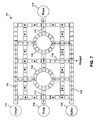
- FIG. 7 illustrates another arrangement 700 of DMF-based electrode platforms designed to carry out a sequence of mix steps.
- the arrangement 700 is similar to the arrangement 600 in that the arrangement 700 includes sample reservoir 702 , buffer reservoir (or second sample reservoir) 704 , and waste reservoir 706 .
- the arrangement 700 employs two DMF rotary mixers 720 and 722 for parallel processing.
- the main objective of using two rotary mixers is to do parallel processing and reducing the inter-step droplet transportation time.
- This advantage is applicable to the subsequent mix/split steps also.
- parallel processing for example, may be used to carry out a first sequence of mix/split steps to produce a first target CF at one rotary mixer, while the other rotary mixer is used to simultaneously carry out a second sequence of mix/split steps to produce a second target CF.
- the same sequence of mix/split steps can be carried out simultaneously on both rotary mixers to produce more than 2 droplets of the target CF (e.g., 4, 6, 8, etc.).
- Carrying out at one rotary mixer a sequence of mix/split steps designed to produce 2 droplets of a target CF, while simultaneously carrying out the same sequence of mix/split steps designed to produce 2 droplets of the target CF on another rotary mixer may produce the 4 target droplets faster than if the sequence was designed to produce 4 droplets of the target CF on a single rotary mixer.
- more than two rotary mixers may be used for faster processing at the expense of chip area.
- the arrangement 700 also includes a plurality of platforms forming sample pathway 708 which is able to transport droplets between sample reservoir 702 and the rotary mixers 720 and 722 .
- Sample pathway 710 is included as well, which is able to transport droplets between the sample reservoir 704 and the rotary mixers 720 and 722 .
- a plurality of platforms forming waste pathway 712 is able to transport droplets between rotary mixer 720 and waste reservoir 706
- a plurality of platforms forming waste pathway 714 is able to transport droplets between rotary mixer 722 and a second waste reservoir 718 .
- Output pathway 716 is included as well and is able to transport droplets from rotary mixers 718 and 720 to an output, such as outside the biochip.
- FIG. 8 is a block diagram illustrating an example computing device 800 that may be associated with a biochip. All or part of computing device 800 may be embedded within a biochip, or a biochip may be designed to couple with all or part of computing device 800 outside of the biochip (e.g., to receive instructions).
- computing device 800 typically includes one or more processors 810 and system memory 820 .
- a memory bus 830 can be used for communicating between the processor 810 and the system memory 820 .
- processor 810 can be of any type including but not limited to a microprocessor ( ⁇ P), a microcontroller ( ⁇ C), a digital signal processor (DSP), or any combination thereof.
- Processor 810 can include one more levels of caching, such as a level one cache 811 and a level two cache 812 , a processor core 813 , and registers 814 .
- the processor core 813 can include an arithmetic logic unit (ALU), a floating point unit (FPU), a digital signal processing core (DSP Core), or any combination thereof.
- a memory controller 815 can also be used with the processor 810 , or in some implementations the memory controller 815 can be an internal part of the processor 810 .
- system memory 820 can be of any type including but not limited to volatile memory (such as RAM), non-volatile memory (such as ROM, flash memory, etc.) or any combination thereof.
- System memory 820 typically includes an operating system 821 , one or more applications 822 , and program data 824 .
- Application 822 may include all or part of the disclosed algorithms. For example, application 822 may receive as an input the desired target concentration factor, the desired unit volume of the target concentration factor, the concentration factors of the initial reagent and buffer solutions, and the precision level i.e., the value of N. The application 822 may responsively determine the appropriate mix/split steps to achieve the desired volume of the target concentration factor. Further, application 822 may determine instructions for carrying out the determined mix/split steps as well. For example, in an DMF device associated with computing device 800 , these instructions may comprise appropriate actuation sequences for causing an array of DMF-based electrode platforms to carry out the determined mix/split steps. Such instructions may take the form of a bit pattern/bit stream, called the actuation sequence for the addressable array of DMF-based electrodes.
- the appropriate actuation sequences may be fed to one or more peripheral interfaces.
- the I/O ports 873 may be coupled to the platforms, and based on the received actuation sequences, apply voltages to the platforms such that the determined sequence of mix steps is carried out.
- Computing device 800 can have additional features or functionality, and additional interfaces to facilitate communications between the basic configuration 801 and any required devices and interfaces.
- a bus/interface controller 840 can be used to facilitate communications between the basic configuration 801 and one or more data storage devices 850 via a storage interface bus 841 .
- the data storage devices 850 can be removable storage devices 851 , non-removable storage devices 852 , or a combination thereof.
- Examples of removable storage and non-removable storage devices include magnetic disk devices such as flexible disk drives and hard-disk drives (HDD), optical disk drives such as compact disk (CD) drives or digital versatile disk (DVD) drives, solid state drives (SSD), and tape drives to name a few.
- Example computer storage media can include volatile and nonvolatile, removable and non-removable media implemented in any method or technology for storage of information, such as computer readable instructions, data structures, program modules, or other data.
- Computer storage media includes, but is not limited to, RAM, ROM, EEPROM, flash memory or other memory technology, CD-ROM, digital versatile disks (DVD) or other optical storage, magnetic cassettes, magnetic tape, magnetic disk storage or other magnetic storage devices, or any other medium which can be used to store the desired information and which can be accessed by computing device 800 . Any such computer storage media can be part of device 800 .
- Computing device 800 can also include an interface bus 842 for facilitating communication from various interface devices (e.g., output interfaces, peripheral interfaces, and communication interfaces) to the basic configuration 801 via the bus/interface controller 840 .
- Example output interfaces 860 include a graphics processing unit 861 and an audio processing unit 862 , which can be configured to communicate to various external devices such as a display or speakers via one or more A/V ports 863 .
- Example peripheral interfaces 860 include a serial interface controller 871 or a parallel interface controller 872 , which can be configured to communicate with external devices such as input devices (e.g., keyboard, mouse, pen, voice input device, touch input device, etc.) or other peripheral devices (e.g., printer, scanner, etc.) via one or more I/O ports 873 .
- An example communication interface 880 includes a network controller 881 , which can be arranged to facilitate communications with one or more other computing devices 890 over a network communication via one or more communication ports 882 .
- the Communication connection is one example of a communication media.
- Communication media may typically be embodied by computer readable instructions, data structures, program modules, or other data in a modulated data signal, such as a carrier wave or other transport mechanism, and includes any information delivery media.
- a “modulated data signal” can be a signal that has one or more of its characteristics set or changed in such a manner as to encode information in the signal.
- communication media can include wired media such as a wired network or direct-wired connection, and wireless media such as acoustic, radio frequency (RF), infrared (IR) and other wireless media.
- RF radio frequency
- IR infrared
- the term computer readable media (or medium) as used herein can include both storage media and communication media.
- Computing device 800 can be implemented as a portion of a digital microfluidic biochip. Computing device 800 can also be implemented as a personal computer including both laptop computer and non-laptop computer configurations.
- a range includes each individual member.
- a group having 1-3 cells refers to groups having 1, 2, or 3 cells.
- a group having 1-5 cells refers to groups having 1, 2, 3, 4, or 5 cells, and so forth.
Abstract
Description
| TABLE 1 | |||||
| | Platform | 112 | |
|
|
| 0 | 1 | 0 | 1 | ||
| 1 | 0 | 1 | 0 | ||
| 2 | 1 | 0 | 1 | ||
| TABLE 2 | ||||||
| Time | Plat- | Plat- | Platform | Platform | | |
| Step | form | |||||
| 1 | | | 17 | 18 | 19 | |
| 0 | 1 | 1 | 1 | 0 | 0 | 0 |
| 1 | 1 | 0 | 1 | 1 | 1 | 0 |
| 2 | 1 | 0 | 1 | 0 | 1 | 0 |
For example, at time step 0, platforms 1-3 are driven high, thus holding the
The numerator, T, may be chosen as any number depending on the application. A T=313, for example, may equate to a target CF of:
and CH may be expressed as:
where:
For example, if a unit-volume of fluid with CF expressed as:
were mixed with a unit-volume fluid with CF expressed as:
the resultant mixture would be 2 unit-volumes of fluid with a CF expressed as:
(N−2).
| TABLE 3 | |||||||
| Number | Number | ||||||
| of | of | ||||||
| droplets | droplets | Number | |||||
| of | of | of | |||||
| lower | higher | droplets | |||||
| Lower | CF | CF | Resultant | pro- | |||
| Step | CF | used | Higher CF | used | | duced | |
| 1 | 0/1024 | 5 | 1024/1024 | 5 | 512/1024 | 10 |
| 2 | 512/1024 | 1 | 1024/1024 | 1 | 768/1024 | 2 |
| 3 | 512/1024 | 1 | 768/1024 | 1 | 640/1024 | 2 |
| 4 | 512/1024 | 1 | 640/1024 | 1 | 576/1024 | 2 |
| 5 | 512/1024 | 1 | 576/1024 | 1 | 544/1024 | 2 |
| 6 | 512/1024 | 1 | 544/1024 | 1 | 528/1024 | 2 |
| 7 | 512/1024 | 1 | 528/1024 | 1 | 520/1024 | 2 |
| 8 | 512/1024 | 1 | 520/1024 | 1 | 516/1024 | 2 |
| 9 | 512/1024 | 1 | 516/1024 | 1 | 514/1024 | 2 |
| 10 | 512/1024 | 1 | 514/1024 | 1 | 513/1024 | 2 |
droplets are needed from each of the constituents. As an example, if N is chosen as 10, then the maximum demand for a particular CF is 10−1=9 droplets. To produce 9 droplets, 5 droplets of each of the constituents are needed. This is expressed by the expression:
So, the total number of droplets of the two constituents to be mixed is expressed by the expression:
Since
droplets may need to be mixed together in one step, the rotary mixer should have at least that many platforms, and should include some additional platforms (e.g., 6 additional platforms) so that a mixture of
droplets can be rotated/stirred and effectively mixed. Therefore, the number of platforms that comprise the rotary mixer can be expressed as:
2(N−2)
storage locations may be needed.
Claims (10)
(N−2).
2(N−2).
Applications Claiming Priority (3)
| Application Number | Priority Date | Filing Date | Title |
|---|---|---|---|
| IN770/KOL/2010 | 2010-07-15 | ||
| IN770KO2010 | 2010-07-15 | ||
| PCT/IB2010/002899 WO2012007787A1 (en) | 2010-07-15 | 2010-11-12 | Architectural layout for dilution with reduced wastage in digital microfluidic based lab-on-a-chip |
Publications (2)
| Publication Number | Publication Date |
|---|---|
| US20130105319A1 US20130105319A1 (en) | 2013-05-02 |
| US9201042B2 true US9201042B2 (en) | 2015-12-01 |
Family
ID=45468985
Family Applications (1)
| Application Number | Title | Priority Date | Filing Date |
|---|---|---|---|
| US13/809,494 Expired - Fee Related US9201042B2 (en) | 2010-07-15 | 2010-11-12 | Architectural layout for dilution with reduced wastage in digital microfluidic based lab-on-a-chip |
Country Status (4)
| Country | Link |
|---|---|
| US (1) | US9201042B2 (en) |
| EP (1) | EP2593228A4 (en) |
| JP (1) | JP5755328B2 (en) |
| WO (1) | WO2012007787A1 (en) |
Cited By (6)
| Publication number | Priority date | Publication date | Assignee | Title |
|---|---|---|---|---|
| US20150306598A1 (en) * | 2014-04-25 | 2015-10-29 | Berkeley Lights, Inc. | DEP Force Control And Electrowetting Control In Different Sections Of The Same Microfluidic Apparatus |
| US10799865B2 (en) | 2015-10-27 | 2020-10-13 | Berkeley Lights, Inc. | Microfluidic apparatus having an optimized electrowetting surface and related systems and methods |
| US10987640B2 (en) * | 2010-06-07 | 2021-04-27 | University Of Florida Research Foundation, Inc. | Plasma induced fluid mixing |
| US11007520B2 (en) | 2016-05-26 | 2021-05-18 | Berkeley Lights, Inc. | Covalently modified surfaces, kits, and methods of preparation and use |
| US11192107B2 (en) * | 2014-04-25 | 2021-12-07 | Berkeley Lights, Inc. | DEP force control and electrowetting control in different sections of the same microfluidic apparatus |
| US11365381B2 (en) | 2015-04-22 | 2022-06-21 | Berkeley Lights, Inc. | Microfluidic cell culture |
Families Citing this family (7)
| Publication number | Priority date | Publication date | Assignee | Title |
|---|---|---|---|---|
| US8734003B2 (en) * | 2005-09-15 | 2014-05-27 | Alcatel Lucent | Micro-chemical mixing |
| US9128014B2 (en) | 2010-07-15 | 2015-09-08 | Indian Statistical Institute | High throughput and volumetric error resilient dilution with digital microfluidic based lab-on-a-chip |
| CN105452839B (en) | 2013-06-21 | 2019-01-15 | 伯乐生命医学产品有限公司 | Microfluidic system with fluid collection pipe |
| US11207685B2 (en) | 2017-02-13 | 2021-12-28 | Bio-Rad Laboratories, Inc. | System, method, and device for forming an array of emulsions |
| US11117131B2 (en) * | 2018-08-22 | 2021-09-14 | International Business Machines Corporation | Electrokinetically separating, encapsulating and extracting analytes on a microfluidic device |
| CN113842962B (en) * | 2021-10-19 | 2023-02-17 | 安图实验仪器(郑州)有限公司 | Concentration homogenization micro-fluidic chip based on electrowetting and concentration homogenization method |
| CN114166615A (en) * | 2021-11-22 | 2022-03-11 | 南方科技大学 | Dilution method of digital microfluidic droplets |
Citations (5)
| Publication number | Priority date | Publication date | Assignee | Title |
|---|---|---|---|---|
| US6565727B1 (en) * | 1999-01-25 | 2003-05-20 | Nanolytics, Inc. | Actuators for microfluidics without moving parts |
| US20040055891A1 (en) | 2002-09-24 | 2004-03-25 | Pamula Vamsee K. | Methods and apparatus for manipulating droplets by electrowetting-based techniques |
| WO2010077859A2 (en) | 2008-12-15 | 2010-07-08 | Advanced Liquid Logic, Inc. | Nucleic acid amplification and sequencing on a droplet actuator |
| US20130105318A1 (en) | 2010-07-15 | 2013-05-02 | Indian Statistical Institute | High throughput and volumetric error resilient dilution with digital microfluidic based lab-on-a-chip |
| US20130115703A1 (en) | 2010-07-15 | 2013-05-09 | Indian Statistical Institute | Dilution method for digital microfluidic biochips |
Family Cites Families (1)
| Publication number | Priority date | Publication date | Assignee | Title |
|---|---|---|---|---|
| WO2009052123A2 (en) * | 2007-10-17 | 2009-04-23 | Advanced Liquid Logic, Inc. | Multiplexed detection schemes for a droplet actuator |
-
2010
- 2010-11-12 JP JP2013519167A patent/JP5755328B2/en not_active Expired - Fee Related
- 2010-11-12 EP EP10854661.5A patent/EP2593228A4/en not_active Withdrawn
- 2010-11-12 WO PCT/IB2010/002899 patent/WO2012007787A1/en active Application Filing
- 2010-11-12 US US13/809,494 patent/US9201042B2/en not_active Expired - Fee Related
Patent Citations (9)
| Publication number | Priority date | Publication date | Assignee | Title |
|---|---|---|---|---|
| US6565727B1 (en) * | 1999-01-25 | 2003-05-20 | Nanolytics, Inc. | Actuators for microfluidics without moving parts |
| US20040031688A1 (en) | 1999-01-25 | 2004-02-19 | Shenderov Alexander David | Actuators for microfluidics without moving parts |
| US20040055891A1 (en) | 2002-09-24 | 2004-03-25 | Pamula Vamsee K. | Methods and apparatus for manipulating droplets by electrowetting-based techniques |
| US6911132B2 (en) | 2002-09-24 | 2005-06-28 | Duke University | Apparatus for manipulating droplets by electrowetting-based techniques |
| JP2006500596A (en) | 2002-09-24 | 2006-01-05 | デューク・ユニバーシティ | Method and apparatus for manipulating droplets using electrowetting technology |
| US7569129B2 (en) | 2002-09-24 | 2009-08-04 | Advanced Liquid Logic, Inc. | Methods for manipulating droplets by electrowetting-based techniques |
| WO2010077859A2 (en) | 2008-12-15 | 2010-07-08 | Advanced Liquid Logic, Inc. | Nucleic acid amplification and sequencing on a droplet actuator |
| US20130105318A1 (en) | 2010-07-15 | 2013-05-02 | Indian Statistical Institute | High throughput and volumetric error resilient dilution with digital microfluidic based lab-on-a-chip |
| US20130115703A1 (en) | 2010-07-15 | 2013-05-09 | Indian Statistical Institute | Dilution method for digital microfluidic biochips |
Non-Patent Citations (22)
| Title |
|---|
| Ding, Jie., et al., " Scheduling of Microfluidic Operations for Reconfigurable Two-dimensional Electrowetting Arrays," IEEE Transactions on Computer-Aided Design of Integrated Circuits and Systems, vol. 20,No. 12, pp. 1463-1468 (Dec. 2001). |
| Fair, "Digital microfluidics: is a true lab-on-a-chip possible?," Microfluidics and Nanofluidics, vol. 3, Jun. 2007, pp. 245-281. |
| Fair, R.B., et al., "Electrowetting-based On-chip Sample Processing for Integrated Microfluidics," IEEE IEDM'03 Technical Digest, pp. 32.5.1-32.5.4 (Dec. 2003). |
| Fair, R.B., et al., "Integrated Chemical/Biochemical Sample Collection, Pre-Concentration, and Analysis on a Digital Microfluidic," in Proceedings of the SPIE Conference on Lab-on-a-Chip: Platforms, Devices, and Applications, vol. 5591, pp. 113-124 (2004). |
| Fouillet, Y., et al ., "Digital microfluidic design and optimization of classic and new fluidic functions for lab on a chip systems," Microfluidics and Nanofluidics, vol. 4, No. 3, pp. 159-165 (Mar. 1, 2008). |
| Griffith, E., and Akella, S., "Coordinating Multiple Droplets in Planar Array Digital Microfluidics System," Algorithmic Foundations of Robotics, vol. 17, pp. 219-234 (Oct. 12, 2005). |
| Griffith, E.J. et al., "Performance Characterization of a Reconfigurable Planar-Array Digital Microfluidic System,"IEEE TCAD, vol. 25, Issue 2, pp. 340-352 (Feb. 2006). |
| International Search Report and Written Opinion from International Application No. PCT/IB2010/002895 dated Apr. 5, 2011. |
| International Search Report and Written Opinion from International Application No. PCT/IB2010/002899 dated Feb. 22, 2011. |
| International Search Report and Written Opinion from International Application No. PCT/IB2010/002911 dated Mar. 9, 2011. |
| Mitra, D., et al., "Accelerated Functional Testing of Digital Microfluidic Biochips," in Proceedings of the 17th Asian Test Symposium (ATS 2008), pp. 295-300 (Nov. 24-27, 2008). |
| Paik, P., et al., "Electrowetting-based Droplet Mixers for Microfluidic Systems," Lab-on-a-Chip, vol. 3, pp. 28-33 (Feb. 3, 2003). |
| Paik, P., et al., "Rapid Droplet Mixers for Digital Microfluidic Systems," Lab-on-a-Chip, vol. 3, pp. 253-259 (Sep. 12, 2003). |
| Ren, H. et al., "Design and Testing of an Interpolating Mixing Architecture for Electrowetting-Based Droplet-On-Chip Chemical Dilution," 12th International Conference on Transducers, Solid-State Sensors, Actuators and Microsystems, vol. 1, pp. 619-622 (Jun. 8-12, 2003). |
| Srinivasan, V., et al.,"An Integrated Digital Microfluidic Lab-on-a-Chip for Clinical Diagnostics on Human Physiological Fluids," Lab-on-a-Chip, vol. 4, No. 4, pp. 310-315, (2004). |
| Thies, "Programable Microfluidics", [retrieved on Mar. 2, 2011]. Retrieved from Internet; Inthttp://replay.waybackmachine.org/20090620134748/http://groups.csail.mit.edu/cag/bios; published on Jun. 20, 2009 as per Wayback Engine. |
| Thies, et al. "Abstraction layers for scalable microfluidic biocomputing," Natural Computing, vol. 7, Jun. 2008, pp. 255-275. |
| Urbanski, J.P., et al., "Digital Microfluidics using Soft Lithography,"Lab Chip, vol. 6, No. 1, pp. 96-104 (2006). |
| Xu, et al, "Automated, Accurate, and Inexpensive Solution-Preparation on a Digital Microfluidic Biochip". Biomedical Circuits and Systems Conference, 2008. BioCAS 2008. pp. 301-304. |
| Xu, T., and Chakrabarty, K., Functional Testing of Digital Microfluidic biochips, in Proceedings of the IEEE International Test Conference (ITC 2007), pp. 1-10 (Oct. 21-26, 2007). |
| Yuh, et al, "Placement of Digital Microfluidic Biochips Using the T-tree Formulation" Design Automation Conference, 2006 43rd ACM. pp. 931-934. |
| Zheng, et al., "A Microfluidic Approach for Screening Submicroliter Volumes against Multiple Reagents by Using Preformed Arrays of Nanoliter Plugs in a Three-Phase Liquid/Liquid/Gas Flow," Angewandte Chemie (International ed. in English), vol. 44, Apr. 2005, pp. 2520-2523. |
Cited By (12)
| Publication number | Priority date | Publication date | Assignee | Title |
|---|---|---|---|---|
| US10987640B2 (en) * | 2010-06-07 | 2021-04-27 | University Of Florida Research Foundation, Inc. | Plasma induced fluid mixing |
| US20150306598A1 (en) * | 2014-04-25 | 2015-10-29 | Berkeley Lights, Inc. | DEP Force Control And Electrowetting Control In Different Sections Of The Same Microfluidic Apparatus |
| KR20160146975A (en) * | 2014-04-25 | 2016-12-21 | 버클리 라잇츠, 인크. | Dep force control and electrowetting control in different sections of the same microfluidic apparatus |
| CN106255888A (en) * | 2014-04-25 | 2016-12-21 | 伯克利照明有限公司 | DEP power in the different piece of same microfluidic device controls and electrowetting controls |
| CN106255888B (en) * | 2014-04-25 | 2019-12-10 | 伯克利之光生命科技公司 | DEP force control and electrowetting control in different sections of the same microfluidic device |
| KR102237846B1 (en) | 2014-04-25 | 2021-04-08 | 버클리 라잇츠, 인크. | Dep force control and electrowetting control in different sections of the same microfluidic apparatus |
| US11192107B2 (en) * | 2014-04-25 | 2021-12-07 | Berkeley Lights, Inc. | DEP force control and electrowetting control in different sections of the same microfluidic apparatus |
| US11365381B2 (en) | 2015-04-22 | 2022-06-21 | Berkeley Lights, Inc. | Microfluidic cell culture |
| US10799865B2 (en) | 2015-10-27 | 2020-10-13 | Berkeley Lights, Inc. | Microfluidic apparatus having an optimized electrowetting surface and related systems and methods |
| US11964275B2 (en) | 2015-10-27 | 2024-04-23 | Berkeley Lights, Inc. | Microfluidic apparatus having an optimized electrowetting surface and related systems and methods |
| US11007520B2 (en) | 2016-05-26 | 2021-05-18 | Berkeley Lights, Inc. | Covalently modified surfaces, kits, and methods of preparation and use |
| US11801508B2 (en) | 2016-05-26 | 2023-10-31 | Berkeley Lights, Inc. | Covalently modified surfaces, kits, and methods of preparation and use |
Also Published As
| Publication number | Publication date |
|---|---|
| JP5755328B2 (en) | 2015-07-29 |
| EP2593228A4 (en) | 2016-07-13 |
| JP2013531253A (en) | 2013-08-01 |
| US20130105319A1 (en) | 2013-05-02 |
| EP2593228A1 (en) | 2013-05-22 |
| WO2012007787A1 (en) | 2012-01-19 |
Similar Documents
| Publication | Publication Date | Title |
|---|---|---|
| US9201042B2 (en) | Architectural layout for dilution with reduced wastage in digital microfluidic based lab-on-a-chip | |
| US9128014B2 (en) | High throughput and volumetric error resilient dilution with digital microfluidic based lab-on-a-chip | |
| Zhang et al. | Digital acoustofluidics enables contactless and programmable liquid handling | |
| Kong et al. | Motorized actuation system to perform droplet operations on printed plastic sheets | |
| Roy et al. | Optimization of dilution and mixing of biochemical samples using digital microfluidic biochips | |
| Vergauwe et al. | A versatile electrowetting-based digital microfluidic platform for quantitative homogeneous and heterogeneous bio-assays | |
| Roy et al. | Waste-aware dilution and mixing of biochemical samples with digital microfluidic biochips | |
| CN101486004B (en) | Automatic device for quantitatively distributing microfluid and using method | |
| Rui et al. | Applications of electrowetting-on-dielectric (EWOD) technology for droplet digital PCR | |
| JP2007285792A (en) | Microchip | |
| JP2007121275A (en) | Microchip and liquid mixing method and blood testing method using microchip | |
| Samiei et al. | Systematic analysis of geometrical based unequal droplet splitting in digital microfluidics | |
| US8557199B2 (en) | Self-powered microfluidic devices, methods and systems | |
| JP2006220606A (en) | Liquid sending device | |
| Roy et al. | Layout-aware solution preparation for biochemical analysis on a digital microfluidic biochip | |
| Araz et al. | Microfluidic multiplexing in bioanalyses | |
| JP5902426B2 (en) | Liquid feeding device and liquid feeding method | |
| Kulinsky et al. | Present technology and future trends in point-of-care microfluidic diagnostics | |
| Masini et al. | Surface-acoustic-wave counterflow micropumps for on-chip liquid motion control in two-dimensional microchannel arrays | |
| Liu et al. | A power-free, parallel loading microfluidic reactor array for biochemical screening | |
| TWI585409B (en) | Diagnostic chip, and method of forming the same | |
| Bhattacharjee et al. | Algorithms for sample preparation with microfluidic lab-on-chip | |
| US20130115703A1 (en) | Dilution method for digital microfluidic biochips | |
| Roy et al. | Waste-aware single-target dilution of a biochemical fluid using digital microfluidic biochips | |
| Wang et al. | An EWOD-based micro diluter with high flexibility on dilution ratio |
Legal Events
| Date | Code | Title | Description |
|---|---|---|---|
| AS | Assignment |
Owner name: INDIAN STATISTICAL INSTITUTE, INDIA Free format text: ASSIGNMENT OF ASSIGNORS INTEREST;ASSIGNORS:BHATTACHARYA, BHARGAB B.;ROY, SUDIP;CHAKRABARTY, KRISHNENDU;REEL/FRAME:029605/0847 Effective date: 20110203 |
|
| STCF | Information on status: patent grant |
Free format text: PATENTED CASE |
|
| CC | Certificate of correction | ||
| AS | Assignment |
Owner name: CRESTLINE DIRECT FINANCE, L.P., TEXAS Free format text: SECURITY INTEREST;ASSIGNOR:EMPIRE TECHNOLOGY DEVELOPMENT LLC;REEL/FRAME:048373/0217 Effective date: 20181228 |
|
| FEPP | Fee payment procedure |
Free format text: MAINTENANCE FEE REMINDER MAILED (ORIGINAL EVENT CODE: REM.); ENTITY STATUS OF PATENT OWNER: LARGE ENTITY |
|
| AS | Assignment |
Owner name: EMPIRE TECHNOLOGY DEVELOPMENT LLC, WASHINGTON Free format text: RELEASE BY SECURED PARTY;ASSIGNOR:CRESTLINE DIRECT FINANCE, L.P.;REEL/FRAME:049924/0794 Effective date: 20190501 |
|
| LAPS | Lapse for failure to pay maintenance fees |
Free format text: PATENT EXPIRED FOR FAILURE TO PAY MAINTENANCE FEES (ORIGINAL EVENT CODE: EXP.); ENTITY STATUS OF PATENT OWNER: LARGE ENTITY |
|
| STCH | Information on status: patent discontinuation |
Free format text: PATENT EXPIRED DUE TO NONPAYMENT OF MAINTENANCE FEES UNDER 37 CFR 1.362 |
|
| FP | Lapsed due to failure to pay maintenance fee |
Effective date: 20191201 |