US9162027B2 - Infusion pump assembly - Google Patents
Infusion pump assembly Download PDFInfo
- Publication number
- US9162027B2 US9162027B2 US13/953,183 US201313953183A US9162027B2 US 9162027 B2 US9162027 B2 US 9162027B2 US 201313953183 A US201313953183 A US 201313953183A US 9162027 B2 US9162027 B2 US 9162027B2
- Authority
- US
- United States
- Prior art keywords
- assembly
- infusion pump
- pump assembly
- reservoir
- fluid
- Prior art date
- Legal status (The legal status is an assumption and is not a legal conclusion. Google has not performed a legal analysis and makes no representation as to the accuracy of the status listed.)
- Active
Links
- 0 C=N**1CC1 Chemical compound C=N**1CC1 0.000 description 7
Images


Classifications
-
- A—HUMAN NECESSITIES
- A61—MEDICAL OR VETERINARY SCIENCE; HYGIENE
- A61M—DEVICES FOR INTRODUCING MEDIA INTO, OR ONTO, THE BODY; DEVICES FOR TRANSDUCING BODY MEDIA OR FOR TAKING MEDIA FROM THE BODY; DEVICES FOR PRODUCING OR ENDING SLEEP OR STUPOR
- A61M5/00—Devices for bringing media into the body in a subcutaneous, intra-vascular or intramuscular way; Accessories therefor, e.g. filling or cleaning devices, arm-rests
- A61M5/14—Infusion devices, e.g. infusing by gravity; Blood infusion; Accessories therefor
- A61M5/158—Needles for infusions; Accessories therefor, e.g. for inserting infusion needles, or for holding them on the body
-
- A—HUMAN NECESSITIES
- A61—MEDICAL OR VETERINARY SCIENCE; HYGIENE
- A61M—DEVICES FOR INTRODUCING MEDIA INTO, OR ONTO, THE BODY; DEVICES FOR TRANSDUCING BODY MEDIA OR FOR TAKING MEDIA FROM THE BODY; DEVICES FOR PRODUCING OR ENDING SLEEP OR STUPOR
- A61M5/00—Devices for bringing media into the body in a subcutaneous, intra-vascular or intramuscular way; Accessories therefor, e.g. filling or cleaning devices, arm-rests
- A61M5/14—Infusion devices, e.g. infusing by gravity; Blood infusion; Accessories therefor
- A61M5/142—Pressure infusion, e.g. using pumps
- A61M5/14212—Pumping with an aspiration and an expulsion action
- A61M5/14216—Reciprocating piston type
-
- A—HUMAN NECESSITIES
- A61—MEDICAL OR VETERINARY SCIENCE; HYGIENE
- A61B—DIAGNOSIS; SURGERY; IDENTIFICATION
- A61B5/00—Measuring for diagnostic purposes; Identification of persons
- A61B5/0002—Remote monitoring of patients using telemetry, e.g. transmission of vital signals via a communication network
- A61B5/0015—Remote monitoring of patients using telemetry, e.g. transmission of vital signals via a communication network characterised by features of the telemetry system
- A61B5/0024—Remote monitoring of patients using telemetry, e.g. transmission of vital signals via a communication network characterised by features of the telemetry system for multiple sensor units attached to the patient, e.g. using a body or personal area network
-
- A—HUMAN NECESSITIES
- A61—MEDICAL OR VETERINARY SCIENCE; HYGIENE
- A61B—DIAGNOSIS; SURGERY; IDENTIFICATION
- A61B5/00—Measuring for diagnostic purposes; Identification of persons
- A61B5/15—Devices for taking samples of blood
- A61B5/150007—Details
- A61B5/150015—Source of blood
- A61B5/150022—Source of blood for capillary blood or interstitial fluid
-
- A—HUMAN NECESSITIES
- A61—MEDICAL OR VETERINARY SCIENCE; HYGIENE
- A61B—DIAGNOSIS; SURGERY; IDENTIFICATION
- A61B5/00—Measuring for diagnostic purposes; Identification of persons
- A61B5/15—Devices for taking samples of blood
- A61B5/150007—Details
- A61B5/150175—Adjustment of penetration depth
-
- A—HUMAN NECESSITIES
- A61—MEDICAL OR VETERINARY SCIENCE; HYGIENE
- A61B—DIAGNOSIS; SURGERY; IDENTIFICATION
- A61B5/00—Measuring for diagnostic purposes; Identification of persons
- A61B5/15—Devices for taking samples of blood
- A61B5/150007—Details
- A61B5/150358—Strips for collecting blood, e.g. absorbent
-
- A—HUMAN NECESSITIES
- A61—MEDICAL OR VETERINARY SCIENCE; HYGIENE
- A61B—DIAGNOSIS; SURGERY; IDENTIFICATION
- A61B5/00—Measuring for diagnostic purposes; Identification of persons
- A61B5/15—Devices for taking samples of blood
- A61B5/150007—Details
- A61B5/150374—Details of piercing elements or protective means for preventing accidental injuries by such piercing elements
- A61B5/150381—Design of piercing elements
- A61B5/150389—Hollow piercing elements, e.g. canulas, needles, for piercing the skin
-
- A—HUMAN NECESSITIES
- A61—MEDICAL OR VETERINARY SCIENCE; HYGIENE
- A61B—DIAGNOSIS; SURGERY; IDENTIFICATION
- A61B5/00—Measuring for diagnostic purposes; Identification of persons
- A61B5/15—Devices for taking samples of blood
- A61B5/150007—Details
- A61B5/150374—Details of piercing elements or protective means for preventing accidental injuries by such piercing elements
- A61B5/150381—Design of piercing elements
- A61B5/150503—Single-ended needles
-
- A—HUMAN NECESSITIES
- A61—MEDICAL OR VETERINARY SCIENCE; HYGIENE
- A61B—DIAGNOSIS; SURGERY; IDENTIFICATION
- A61B5/00—Measuring for diagnostic purposes; Identification of persons
- A61B5/15—Devices for taking samples of blood
- A61B5/151—Devices specially adapted for taking samples of capillary blood, e.g. by lancets, needles or blades
- A61B5/15101—Details
- A61B5/15115—Driving means for propelling the piercing element to pierce the skin, e.g. comprising mechanisms based on shape memory alloys, magnetism, solenoids, piezoelectric effect, biased elements, resilient elements, vacuum or compressed fluids
- A61B5/15117—Driving means for propelling the piercing element to pierce the skin, e.g. comprising mechanisms based on shape memory alloys, magnetism, solenoids, piezoelectric effect, biased elements, resilient elements, vacuum or compressed fluids comprising biased elements, resilient elements or a spring, e.g. a helical spring, leaf spring, or elastic strap
-
- A—HUMAN NECESSITIES
- A61—MEDICAL OR VETERINARY SCIENCE; HYGIENE
- A61B—DIAGNOSIS; SURGERY; IDENTIFICATION
- A61B5/00—Measuring for diagnostic purposes; Identification of persons
- A61B5/15—Devices for taking samples of blood
- A61B5/151—Devices specially adapted for taking samples of capillary blood, e.g. by lancets, needles or blades
- A61B5/15186—Devices loaded with a single lancet, i.e. a single lancet with or without a casing is loaded into a reusable drive device and then discarded after use; drive devices reloadable for multiple use
-
- A—HUMAN NECESSITIES
- A61—MEDICAL OR VETERINARY SCIENCE; HYGIENE
- A61B—DIAGNOSIS; SURGERY; IDENTIFICATION
- A61B5/00—Measuring for diagnostic purposes; Identification of persons
- A61B5/68—Arrangements of detecting, measuring or recording means, e.g. sensors, in relation to patient
- A61B5/6801—Arrangements of detecting, measuring or recording means, e.g. sensors, in relation to patient specially adapted to be attached to or worn on the body surface
- A61B5/683—Means for maintaining contact with the body
- A61B5/6832—Means for maintaining contact with the body using adhesives
- A61B5/6833—Adhesive patches
-
- A—HUMAN NECESSITIES
- A61—MEDICAL OR VETERINARY SCIENCE; HYGIENE
- A61M—DEVICES FOR INTRODUCING MEDIA INTO, OR ONTO, THE BODY; DEVICES FOR TRANSDUCING BODY MEDIA OR FOR TAKING MEDIA FROM THE BODY; DEVICES FOR PRODUCING OR ENDING SLEEP OR STUPOR
- A61M5/00—Devices for bringing media into the body in a subcutaneous, intra-vascular or intramuscular way; Accessories therefor, e.g. filling or cleaning devices, arm-rests
- A61M5/14—Infusion devices, e.g. infusing by gravity; Blood infusion; Accessories therefor
- A61M5/1413—Modular systems comprising interconnecting elements
-
- A—HUMAN NECESSITIES
- A61—MEDICAL OR VETERINARY SCIENCE; HYGIENE
- A61M—DEVICES FOR INTRODUCING MEDIA INTO, OR ONTO, THE BODY; DEVICES FOR TRANSDUCING BODY MEDIA OR FOR TAKING MEDIA FROM THE BODY; DEVICES FOR PRODUCING OR ENDING SLEEP OR STUPOR
- A61M5/00—Devices for bringing media into the body in a subcutaneous, intra-vascular or intramuscular way; Accessories therefor, e.g. filling or cleaning devices, arm-rests
- A61M5/14—Infusion devices, e.g. infusing by gravity; Blood infusion; Accessories therefor
- A61M5/142—Pressure infusion, e.g. using pumps
- A61M5/14212—Pumping with an aspiration and an expulsion action
- A61M5/14224—Diaphragm type
-
- A—HUMAN NECESSITIES
- A61—MEDICAL OR VETERINARY SCIENCE; HYGIENE
- A61M—DEVICES FOR INTRODUCING MEDIA INTO, OR ONTO, THE BODY; DEVICES FOR TRANSDUCING BODY MEDIA OR FOR TAKING MEDIA FROM THE BODY; DEVICES FOR PRODUCING OR ENDING SLEEP OR STUPOR
- A61M5/00—Devices for bringing media into the body in a subcutaneous, intra-vascular or intramuscular way; Accessories therefor, e.g. filling or cleaning devices, arm-rests
- A61M5/14—Infusion devices, e.g. infusing by gravity; Blood infusion; Accessories therefor
- A61M5/142—Pressure infusion, e.g. using pumps
- A61M5/14212—Pumping with an aspiration and an expulsion action
- A61M5/14232—Roller pumps
-
- A—HUMAN NECESSITIES
- A61—MEDICAL OR VETERINARY SCIENCE; HYGIENE
- A61M—DEVICES FOR INTRODUCING MEDIA INTO, OR ONTO, THE BODY; DEVICES FOR TRANSDUCING BODY MEDIA OR FOR TAKING MEDIA FROM THE BODY; DEVICES FOR PRODUCING OR ENDING SLEEP OR STUPOR
- A61M5/00—Devices for bringing media into the body in a subcutaneous, intra-vascular or intramuscular way; Accessories therefor, e.g. filling or cleaning devices, arm-rests
- A61M5/14—Infusion devices, e.g. infusing by gravity; Blood infusion; Accessories therefor
- A61M5/142—Pressure infusion, e.g. using pumps
- A61M5/14244—Pressure infusion, e.g. using pumps adapted to be carried by the patient, e.g. portable on the body
- A61M5/14248—Pressure infusion, e.g. using pumps adapted to be carried by the patient, e.g. portable on the body of the skin patch type
-
- A—HUMAN NECESSITIES
- A61—MEDICAL OR VETERINARY SCIENCE; HYGIENE
- A61M—DEVICES FOR INTRODUCING MEDIA INTO, OR ONTO, THE BODY; DEVICES FOR TRANSDUCING BODY MEDIA OR FOR TAKING MEDIA FROM THE BODY; DEVICES FOR PRODUCING OR ENDING SLEEP OR STUPOR
- A61M5/00—Devices for bringing media into the body in a subcutaneous, intra-vascular or intramuscular way; Accessories therefor, e.g. filling or cleaning devices, arm-rests
- A61M5/14—Infusion devices, e.g. infusing by gravity; Blood infusion; Accessories therefor
- A61M5/142—Pressure infusion, e.g. using pumps
- A61M5/145—Pressure infusion, e.g. using pumps using pressurised reservoirs, e.g. pressurised by means of pistons
- A61M5/1452—Pressure infusion, e.g. using pumps using pressurised reservoirs, e.g. pressurised by means of pistons pressurised by means of pistons
-
- A—HUMAN NECESSITIES
- A61—MEDICAL OR VETERINARY SCIENCE; HYGIENE
- A61M—DEVICES FOR INTRODUCING MEDIA INTO, OR ONTO, THE BODY; DEVICES FOR TRANSDUCING BODY MEDIA OR FOR TAKING MEDIA FROM THE BODY; DEVICES FOR PRODUCING OR ENDING SLEEP OR STUPOR
- A61M5/00—Devices for bringing media into the body in a subcutaneous, intra-vascular or intramuscular way; Accessories therefor, e.g. filling or cleaning devices, arm-rests
- A61M5/14—Infusion devices, e.g. infusing by gravity; Blood infusion; Accessories therefor
- A61M5/142—Pressure infusion, e.g. using pumps
- A61M5/145—Pressure infusion, e.g. using pumps using pressurised reservoirs, e.g. pressurised by means of pistons
- A61M5/14586—Pressure infusion, e.g. using pumps using pressurised reservoirs, e.g. pressurised by means of pistons pressurised by means of a flexible diaphragm
-
- A—HUMAN NECESSITIES
- A61—MEDICAL OR VETERINARY SCIENCE; HYGIENE
- A61M—DEVICES FOR INTRODUCING MEDIA INTO, OR ONTO, THE BODY; DEVICES FOR TRANSDUCING BODY MEDIA OR FOR TAKING MEDIA FROM THE BODY; DEVICES FOR PRODUCING OR ENDING SLEEP OR STUPOR
- A61M5/00—Devices for bringing media into the body in a subcutaneous, intra-vascular or intramuscular way; Accessories therefor, e.g. filling or cleaning devices, arm-rests
- A61M5/14—Infusion devices, e.g. infusing by gravity; Blood infusion; Accessories therefor
- A61M5/142—Pressure infusion, e.g. using pumps
- A61M5/145—Pressure infusion, e.g. using pumps using pressurised reservoirs, e.g. pressurised by means of pistons
- A61M5/148—Pressure infusion, e.g. using pumps using pressurised reservoirs, e.g. pressurised by means of pistons flexible, e.g. independent bags
-
- A—HUMAN NECESSITIES
- A61—MEDICAL OR VETERINARY SCIENCE; HYGIENE
- A61M—DEVICES FOR INTRODUCING MEDIA INTO, OR ONTO, THE BODY; DEVICES FOR TRANSDUCING BODY MEDIA OR FOR TAKING MEDIA FROM THE BODY; DEVICES FOR PRODUCING OR ENDING SLEEP OR STUPOR
- A61M5/00—Devices for bringing media into the body in a subcutaneous, intra-vascular or intramuscular way; Accessories therefor, e.g. filling or cleaning devices, arm-rests
- A61M5/14—Infusion devices, e.g. infusing by gravity; Blood infusion; Accessories therefor
- A61M5/162—Needle sets, i.e. connections by puncture between reservoir and tube ; Connections between reservoir and tube
-
- A—HUMAN NECESSITIES
- A61—MEDICAL OR VETERINARY SCIENCE; HYGIENE
- A61M—DEVICES FOR INTRODUCING MEDIA INTO, OR ONTO, THE BODY; DEVICES FOR TRANSDUCING BODY MEDIA OR FOR TAKING MEDIA FROM THE BODY; DEVICES FOR PRODUCING OR ENDING SLEEP OR STUPOR
- A61M5/00—Devices for bringing media into the body in a subcutaneous, intra-vascular or intramuscular way; Accessories therefor, e.g. filling or cleaning devices, arm-rests
- A61M5/14—Infusion devices, e.g. infusing by gravity; Blood infusion; Accessories therefor
- A61M5/168—Means for controlling media flow to the body or for metering media to the body, e.g. drip meters, counters ; Monitoring media flow to the body
- A61M5/16804—Flow controllers
- A61M5/16809—Flow controllers by repeated filling and emptying of an intermediate volume
-
- A—HUMAN NECESSITIES
- A61—MEDICAL OR VETERINARY SCIENCE; HYGIENE
- A61M—DEVICES FOR INTRODUCING MEDIA INTO, OR ONTO, THE BODY; DEVICES FOR TRANSDUCING BODY MEDIA OR FOR TAKING MEDIA FROM THE BODY; DEVICES FOR PRODUCING OR ENDING SLEEP OR STUPOR
- A61M5/00—Devices for bringing media into the body in a subcutaneous, intra-vascular or intramuscular way; Accessories therefor, e.g. filling or cleaning devices, arm-rests
- A61M5/14—Infusion devices, e.g. infusing by gravity; Blood infusion; Accessories therefor
- A61M5/168—Means for controlling media flow to the body or for metering media to the body, e.g. drip meters, counters ; Monitoring media flow to the body
- A61M5/16804—Flow controllers
- A61M5/16813—Flow controllers by controlling the degree of opening of the flow line
-
- A—HUMAN NECESSITIES
- A61—MEDICAL OR VETERINARY SCIENCE; HYGIENE
- A61M—DEVICES FOR INTRODUCING MEDIA INTO, OR ONTO, THE BODY; DEVICES FOR TRANSDUCING BODY MEDIA OR FOR TAKING MEDIA FROM THE BODY; DEVICES FOR PRODUCING OR ENDING SLEEP OR STUPOR
- A61M5/00—Devices for bringing media into the body in a subcutaneous, intra-vascular or intramuscular way; Accessories therefor, e.g. filling or cleaning devices, arm-rests
- A61M5/14—Infusion devices, e.g. infusing by gravity; Blood infusion; Accessories therefor
- A61M5/168—Means for controlling media flow to the body or for metering media to the body, e.g. drip meters, counters ; Monitoring media flow to the body
- A61M5/16831—Monitoring, detecting, signalling or eliminating infusion flow anomalies
-
- A—HUMAN NECESSITIES
- A61—MEDICAL OR VETERINARY SCIENCE; HYGIENE
- A61M—DEVICES FOR INTRODUCING MEDIA INTO, OR ONTO, THE BODY; DEVICES FOR TRANSDUCING BODY MEDIA OR FOR TAKING MEDIA FROM THE BODY; DEVICES FOR PRODUCING OR ENDING SLEEP OR STUPOR
- A61M5/00—Devices for bringing media into the body in a subcutaneous, intra-vascular or intramuscular way; Accessories therefor, e.g. filling or cleaning devices, arm-rests
- A61M5/14—Infusion devices, e.g. infusing by gravity; Blood infusion; Accessories therefor
- A61M5/168—Means for controlling media flow to the body or for metering media to the body, e.g. drip meters, counters ; Monitoring media flow to the body
- A61M5/16886—Means for controlling media flow to the body or for metering media to the body, e.g. drip meters, counters ; Monitoring media flow to the body for measuring fluid flow rate, i.e. flowmeters
-
- A—HUMAN NECESSITIES
- A61—MEDICAL OR VETERINARY SCIENCE; HYGIENE
- A61M—DEVICES FOR INTRODUCING MEDIA INTO, OR ONTO, THE BODY; DEVICES FOR TRANSDUCING BODY MEDIA OR FOR TAKING MEDIA FROM THE BODY; DEVICES FOR PRODUCING OR ENDING SLEEP OR STUPOR
- A61M5/00—Devices for bringing media into the body in a subcutaneous, intra-vascular or intramuscular way; Accessories therefor, e.g. filling or cleaning devices, arm-rests
- A61M5/14—Infusion devices, e.g. infusing by gravity; Blood infusion; Accessories therefor
- A61M5/168—Means for controlling media flow to the body or for metering media to the body, e.g. drip meters, counters ; Monitoring media flow to the body
- A61M5/172—Means for controlling media flow to the body or for metering media to the body, e.g. drip meters, counters ; Monitoring media flow to the body electrical or electronic
- A61M5/1723—Means for controlling media flow to the body or for metering media to the body, e.g. drip meters, counters ; Monitoring media flow to the body electrical or electronic using feedback of body parameters, e.g. blood-sugar, pressure
-
- A—HUMAN NECESSITIES
- A61—MEDICAL OR VETERINARY SCIENCE; HYGIENE
- A61M—DEVICES FOR INTRODUCING MEDIA INTO, OR ONTO, THE BODY; DEVICES FOR TRANSDUCING BODY MEDIA OR FOR TAKING MEDIA FROM THE BODY; DEVICES FOR PRODUCING OR ENDING SLEEP OR STUPOR
- A61M5/00—Devices for bringing media into the body in a subcutaneous, intra-vascular or intramuscular way; Accessories therefor, e.g. filling or cleaning devices, arm-rests
- A61M5/178—Syringes
- A61M5/31—Details
- A61M5/32—Needles; Details of needles pertaining to their connection with syringe or hub; Accessories for bringing the needle into, or holding the needle on, the body; Devices for protection of needles
- A61M5/3287—Accessories for bringing the needle into the body; Automatic needle insertion
-
- A—HUMAN NECESSITIES
- A61—MEDICAL OR VETERINARY SCIENCE; HYGIENE
- A61M—DEVICES FOR INTRODUCING MEDIA INTO, OR ONTO, THE BODY; DEVICES FOR TRANSDUCING BODY MEDIA OR FOR TAKING MEDIA FROM THE BODY; DEVICES FOR PRODUCING OR ENDING SLEEP OR STUPOR
- A61M5/00—Devices for bringing media into the body in a subcutaneous, intra-vascular or intramuscular way; Accessories therefor, e.g. filling or cleaning devices, arm-rests
- A61M5/36—Devices for bringing media into the body in a subcutaneous, intra-vascular or intramuscular way; Accessories therefor, e.g. filling or cleaning devices, arm-rests with means for eliminating or preventing injection or infusion of air into body
- A61M5/365—Air detectors
-
- A—HUMAN NECESSITIES
- A61—MEDICAL OR VETERINARY SCIENCE; HYGIENE
- A61M—DEVICES FOR INTRODUCING MEDIA INTO, OR ONTO, THE BODY; DEVICES FOR TRANSDUCING BODY MEDIA OR FOR TAKING MEDIA FROM THE BODY; DEVICES FOR PRODUCING OR ENDING SLEEP OR STUPOR
- A61M5/00—Devices for bringing media into the body in a subcutaneous, intra-vascular or intramuscular way; Accessories therefor, e.g. filling or cleaning devices, arm-rests
- A61M5/50—Devices for bringing media into the body in a subcutaneous, intra-vascular or intramuscular way; Accessories therefor, e.g. filling or cleaning devices, arm-rests having means for preventing re-use, or for indicating if defective, used, tampered with or unsterile
- A61M5/5086—Devices for bringing media into the body in a subcutaneous, intra-vascular or intramuscular way; Accessories therefor, e.g. filling or cleaning devices, arm-rests having means for preventing re-use, or for indicating if defective, used, tampered with or unsterile for indicating if defective, used, tampered with or unsterile
-
- B—PERFORMING OPERATIONS; TRANSPORTING
- B23—MACHINE TOOLS; METAL-WORKING NOT OTHERWISE PROVIDED FOR
- B23P—METAL-WORKING NOT OTHERWISE PROVIDED FOR; COMBINED OPERATIONS; UNIVERSAL MACHINE TOOLS
- B23P15/00—Making specific metal objects by operations not covered by a single other subclass or a group in this subclass
-
- F—MECHANICAL ENGINEERING; LIGHTING; HEATING; WEAPONS; BLASTING
- F04—POSITIVE - DISPLACEMENT MACHINES FOR LIQUIDS; PUMPS FOR LIQUIDS OR ELASTIC FLUIDS
- F04B—POSITIVE-DISPLACEMENT MACHINES FOR LIQUIDS; PUMPS
- F04B43/00—Machines, pumps, or pumping installations having flexible working members
- F04B43/02—Machines, pumps, or pumping installations having flexible working members having plate-like flexible members, e.g. diaphragms
-
- F—MECHANICAL ENGINEERING; LIGHTING; HEATING; WEAPONS; BLASTING
- F04—POSITIVE - DISPLACEMENT MACHINES FOR LIQUIDS; PUMPS FOR LIQUIDS OR ELASTIC FLUIDS
- F04B—POSITIVE-DISPLACEMENT MACHINES FOR LIQUIDS; PUMPS
- F04B43/00—Machines, pumps, or pumping installations having flexible working members
- F04B43/08—Machines, pumps, or pumping installations having flexible working members having tubular flexible members
- F04B43/09—Pumps having electric drive
-
- F—MECHANICAL ENGINEERING; LIGHTING; HEATING; WEAPONS; BLASTING
- F04—POSITIVE - DISPLACEMENT MACHINES FOR LIQUIDS; PUMPS FOR LIQUIDS OR ELASTIC FLUIDS
- F04B—POSITIVE-DISPLACEMENT MACHINES FOR LIQUIDS; PUMPS
- F04B7/00—Piston machines or pumps characterised by having positively-driven valving
-
- G—PHYSICS
- G01—MEASURING; TESTING
- G01F—MEASURING VOLUME, VOLUME FLOW, MASS FLOW OR LIQUID LEVEL; METERING BY VOLUME
- G01F22/00—Methods or apparatus for measuring volume of fluids or fluent solid material, not otherwise provided for
-
- G—PHYSICS
- G05—CONTROLLING; REGULATING
- G05B—CONTROL OR REGULATING SYSTEMS IN GENERAL; FUNCTIONAL ELEMENTS OF SUCH SYSTEMS; MONITORING OR TESTING ARRANGEMENTS FOR SUCH SYSTEMS OR ELEMENTS
- G05B23/00—Testing or monitoring of control systems or parts thereof
- G05B23/02—Electric testing or monitoring
-
- G—PHYSICS
- G05—CONTROLLING; REGULATING
- G05D—SYSTEMS FOR CONTROLLING OR REGULATING NON-ELECTRIC VARIABLES
- G05D7/00—Control of flow
- G05D7/06—Control of flow characterised by the use of electric means
- G05D7/0617—Control of flow characterised by the use of electric means specially adapted for fluid materials
- G05D7/0629—Control of flow characterised by the use of electric means specially adapted for fluid materials characterised by the type of regulator means
- G05D7/0635—Control of flow characterised by the use of electric means specially adapted for fluid materials characterised by the type of regulator means by action on throttling means
- G05D7/0641—Control of flow characterised by the use of electric means specially adapted for fluid materials characterised by the type of regulator means by action on throttling means using a plurality of throttling means
- G05D7/0647—Control of flow characterised by the use of electric means specially adapted for fluid materials characterised by the type of regulator means by action on throttling means using a plurality of throttling means the plurality of throttling means being arranged in series
-
- G—PHYSICS
- G05—CONTROLLING; REGULATING
- G05D—SYSTEMS FOR CONTROLLING OR REGULATING NON-ELECTRIC VARIABLES
- G05D7/00—Control of flow
- G05D7/06—Control of flow characterised by the use of electric means
- G05D7/0617—Control of flow characterised by the use of electric means specially adapted for fluid materials
- G05D7/0629—Control of flow characterised by the use of electric means specially adapted for fluid materials characterised by the type of regulator means
- G05D7/0676—Control of flow characterised by the use of electric means specially adapted for fluid materials characterised by the type of regulator means by action on flow sources
-
- G—PHYSICS
- G08—SIGNALLING
- G08C—TRANSMISSION SYSTEMS FOR MEASURED VALUES, CONTROL OR SIMILAR SIGNALS
- G08C17/00—Arrangements for transmitting signals characterised by the use of a wireless electrical link
- G08C17/02—Arrangements for transmitting signals characterised by the use of a wireless electrical link using a radio link
-
- H—ELECTRICITY
- H04—ELECTRIC COMMUNICATION TECHNIQUE
- H04B—TRANSMISSION
- H04B7/00—Radio transmission systems, i.e. using radiation field
- H04B7/24—Radio transmission systems, i.e. using radiation field for communication between two or more posts
- H04B7/26—Radio transmission systems, i.e. using radiation field for communication between two or more posts at least one of which is mobile
- H04B7/2603—Arrangements for wireless physical layer control
- H04B7/2609—Arrangements for range control, e.g. by using remote antennas
-
- A—HUMAN NECESSITIES
- A61—MEDICAL OR VETERINARY SCIENCE; HYGIENE
- A61B—DIAGNOSIS; SURGERY; IDENTIFICATION
- A61B2560/00—Constructional details of operational features of apparatus; Accessories for medical measuring apparatus
- A61B2560/04—Constructional details of apparatus
- A61B2560/0406—Constructional details of apparatus specially shaped apparatus housings
- A61B2560/0412—Low-profile patch shaped housings
-
- A—HUMAN NECESSITIES
- A61—MEDICAL OR VETERINARY SCIENCE; HYGIENE
- A61B—DIAGNOSIS; SURGERY; IDENTIFICATION
- A61B5/00—Measuring for diagnostic purposes; Identification of persons
- A61B5/14—Devices for taking samples of blood ; Measuring characteristics of blood in vivo, e.g. gas concentration within the blood, pH-value of blood
- A61B5/1405—Devices for taking blood samples
- A61B5/1427—Multiple blood sampling, e.g. at periodic or pre-established intervals
-
- A—HUMAN NECESSITIES
- A61—MEDICAL OR VETERINARY SCIENCE; HYGIENE
- A61B—DIAGNOSIS; SURGERY; IDENTIFICATION
- A61B5/00—Measuring for diagnostic purposes; Identification of persons
- A61B5/15—Devices for taking samples of blood
- A61B5/151—Devices specially adapted for taking samples of capillary blood, e.g. by lancets, needles or blades
- A61B5/15101—Details
- A61B5/15103—Piercing procedure
- A61B5/15107—Piercing being assisted by a triggering mechanism
-
- A—HUMAN NECESSITIES
- A61—MEDICAL OR VETERINARY SCIENCE; HYGIENE
- A61B—DIAGNOSIS; SURGERY; IDENTIFICATION
- A61B5/00—Measuring for diagnostic purposes; Identification of persons
- A61B5/15—Devices for taking samples of blood
- A61B5/151—Devices specially adapted for taking samples of capillary blood, e.g. by lancets, needles or blades
- A61B5/15101—Details
- A61B5/15115—Driving means for propelling the piercing element to pierce the skin, e.g. comprising mechanisms based on shape memory alloys, magnetism, solenoids, piezoelectric effect, biased elements, resilient elements, vacuum or compressed fluids
- A61B5/15119—Driving means for propelling the piercing element to pierce the skin, e.g. comprising mechanisms based on shape memory alloys, magnetism, solenoids, piezoelectric effect, biased elements, resilient elements, vacuum or compressed fluids comprising shape memory alloys
-
- A—HUMAN NECESSITIES
- A61—MEDICAL OR VETERINARY SCIENCE; HYGIENE
- A61B—DIAGNOSIS; SURGERY; IDENTIFICATION
- A61B5/00—Measuring for diagnostic purposes; Identification of persons
- A61B5/15—Devices for taking samples of blood
- A61B5/151—Devices specially adapted for taking samples of capillary blood, e.g. by lancets, needles or blades
- A61B5/15101—Details
- A61B5/15115—Driving means for propelling the piercing element to pierce the skin, e.g. comprising mechanisms based on shape memory alloys, magnetism, solenoids, piezoelectric effect, biased elements, resilient elements, vacuum or compressed fluids
- A61B5/15121—Driving means for propelling the piercing element to pierce the skin, e.g. comprising mechanisms based on shape memory alloys, magnetism, solenoids, piezoelectric effect, biased elements, resilient elements, vacuum or compressed fluids comprising piezos
-
- A—HUMAN NECESSITIES
- A61—MEDICAL OR VETERINARY SCIENCE; HYGIENE
- A61B—DIAGNOSIS; SURGERY; IDENTIFICATION
- A61B5/00—Measuring for diagnostic purposes; Identification of persons
- A61B5/15—Devices for taking samples of blood
- A61B5/151—Devices specially adapted for taking samples of capillary blood, e.g. by lancets, needles or blades
- A61B5/15101—Details
- A61B5/15115—Driving means for propelling the piercing element to pierce the skin, e.g. comprising mechanisms based on shape memory alloys, magnetism, solenoids, piezoelectric effect, biased elements, resilient elements, vacuum or compressed fluids
- A61B5/15123—Driving means for propelling the piercing element to pierce the skin, e.g. comprising mechanisms based on shape memory alloys, magnetism, solenoids, piezoelectric effect, biased elements, resilient elements, vacuum or compressed fluids comprising magnets or solenoids
-
- A—HUMAN NECESSITIES
- A61—MEDICAL OR VETERINARY SCIENCE; HYGIENE
- A61B—DIAGNOSIS; SURGERY; IDENTIFICATION
- A61B5/00—Measuring for diagnostic purposes; Identification of persons
- A61B5/15—Devices for taking samples of blood
- A61B5/151—Devices specially adapted for taking samples of capillary blood, e.g. by lancets, needles or blades
- A61B5/15101—Details
- A61B5/15115—Driving means for propelling the piercing element to pierce the skin, e.g. comprising mechanisms based on shape memory alloys, magnetism, solenoids, piezoelectric effect, biased elements, resilient elements, vacuum or compressed fluids
- A61B5/15125—Driving means for propelling the piercing element to pierce the skin, e.g. comprising mechanisms based on shape memory alloys, magnetism, solenoids, piezoelectric effect, biased elements, resilient elements, vacuum or compressed fluids comprising a vacuum or compressed fluids
-
- A—HUMAN NECESSITIES
- A61—MEDICAL OR VETERINARY SCIENCE; HYGIENE
- A61J—CONTAINERS SPECIALLY ADAPTED FOR MEDICAL OR PHARMACEUTICAL PURPOSES; DEVICES OR METHODS SPECIALLY ADAPTED FOR BRINGING PHARMACEUTICAL PRODUCTS INTO PARTICULAR PHYSICAL OR ADMINISTERING FORMS; DEVICES FOR ADMINISTERING FOOD OR MEDICINES ORALLY; BABY COMFORTERS; DEVICES FOR RECEIVING SPITTLE
- A61J1/00—Containers specially adapted for medical or pharmaceutical purposes
- A61J1/14—Details; Accessories therefor
- A61J1/20—Arrangements for transferring or mixing fluids, e.g. from vial to syringe
-
- A—HUMAN NECESSITIES
- A61—MEDICAL OR VETERINARY SCIENCE; HYGIENE
- A61M—DEVICES FOR INTRODUCING MEDIA INTO, OR ONTO, THE BODY; DEVICES FOR TRANSDUCING BODY MEDIA OR FOR TAKING MEDIA FROM THE BODY; DEVICES FOR PRODUCING OR ENDING SLEEP OR STUPOR
- A61M5/00—Devices for bringing media into the body in a subcutaneous, intra-vascular or intramuscular way; Accessories therefor, e.g. filling or cleaning devices, arm-rests
- A61M5/14—Infusion devices, e.g. infusing by gravity; Blood infusion; Accessories therefor
- A61M2005/1401—Functional features
- A61M2005/1402—Priming
-
- A—HUMAN NECESSITIES
- A61—MEDICAL OR VETERINARY SCIENCE; HYGIENE
- A61M—DEVICES FOR INTRODUCING MEDIA INTO, OR ONTO, THE BODY; DEVICES FOR TRANSDUCING BODY MEDIA OR FOR TAKING MEDIA FROM THE BODY; DEVICES FOR PRODUCING OR ENDING SLEEP OR STUPOR
- A61M5/00—Devices for bringing media into the body in a subcutaneous, intra-vascular or intramuscular way; Accessories therefor, e.g. filling or cleaning devices, arm-rests
- A61M5/14—Infusion devices, e.g. infusing by gravity; Blood infusion; Accessories therefor
- A61M5/142—Pressure infusion, e.g. using pumps
- A61M2005/14208—Pressure infusion, e.g. using pumps with a programmable infusion control system, characterised by the infusion program
-
- A—HUMAN NECESSITIES
- A61—MEDICAL OR VETERINARY SCIENCE; HYGIENE
- A61M—DEVICES FOR INTRODUCING MEDIA INTO, OR ONTO, THE BODY; DEVICES FOR TRANSDUCING BODY MEDIA OR FOR TAKING MEDIA FROM THE BODY; DEVICES FOR PRODUCING OR ENDING SLEEP OR STUPOR
- A61M5/00—Devices for bringing media into the body in a subcutaneous, intra-vascular or intramuscular way; Accessories therefor, e.g. filling or cleaning devices, arm-rests
- A61M5/14—Infusion devices, e.g. infusing by gravity; Blood infusion; Accessories therefor
- A61M5/142—Pressure infusion, e.g. using pumps
- A61M5/14244—Pressure infusion, e.g. using pumps adapted to be carried by the patient, e.g. portable on the body
- A61M5/14248—Pressure infusion, e.g. using pumps adapted to be carried by the patient, e.g. portable on the body of the skin patch type
- A61M2005/14252—Pressure infusion, e.g. using pumps adapted to be carried by the patient, e.g. portable on the body of the skin patch type with needle insertion means
-
- A—HUMAN NECESSITIES
- A61—MEDICAL OR VETERINARY SCIENCE; HYGIENE
- A61M—DEVICES FOR INTRODUCING MEDIA INTO, OR ONTO, THE BODY; DEVICES FOR TRANSDUCING BODY MEDIA OR FOR TAKING MEDIA FROM THE BODY; DEVICES FOR PRODUCING OR ENDING SLEEP OR STUPOR
- A61M5/00—Devices for bringing media into the body in a subcutaneous, intra-vascular or intramuscular way; Accessories therefor, e.g. filling or cleaning devices, arm-rests
- A61M5/14—Infusion devices, e.g. infusing by gravity; Blood infusion; Accessories therefor
- A61M5/142—Pressure infusion, e.g. using pumps
- A61M5/14244—Pressure infusion, e.g. using pumps adapted to be carried by the patient, e.g. portable on the body
- A61M2005/14268—Pressure infusion, e.g. using pumps adapted to be carried by the patient, e.g. portable on the body with a reusable and a disposable component
-
- A—HUMAN NECESSITIES
- A61—MEDICAL OR VETERINARY SCIENCE; HYGIENE
- A61M—DEVICES FOR INTRODUCING MEDIA INTO, OR ONTO, THE BODY; DEVICES FOR TRANSDUCING BODY MEDIA OR FOR TAKING MEDIA FROM THE BODY; DEVICES FOR PRODUCING OR ENDING SLEEP OR STUPOR
- A61M5/00—Devices for bringing media into the body in a subcutaneous, intra-vascular or intramuscular way; Accessories therefor, e.g. filling or cleaning devices, arm-rests
- A61M5/14—Infusion devices, e.g. infusing by gravity; Blood infusion; Accessories therefor
- A61M5/142—Pressure infusion, e.g. using pumps
- A61M5/145—Pressure infusion, e.g. using pumps using pressurised reservoirs, e.g. pressurised by means of pistons
- A61M2005/14506—Pressure infusion, e.g. using pumps using pressurised reservoirs, e.g. pressurised by means of pistons mechanically driven, e.g. spring or clockwork
-
- A—HUMAN NECESSITIES
- A61—MEDICAL OR VETERINARY SCIENCE; HYGIENE
- A61M—DEVICES FOR INTRODUCING MEDIA INTO, OR ONTO, THE BODY; DEVICES FOR TRANSDUCING BODY MEDIA OR FOR TAKING MEDIA FROM THE BODY; DEVICES FOR PRODUCING OR ENDING SLEEP OR STUPOR
- A61M5/00—Devices for bringing media into the body in a subcutaneous, intra-vascular or intramuscular way; Accessories therefor, e.g. filling or cleaning devices, arm-rests
- A61M5/14—Infusion devices, e.g. infusing by gravity; Blood infusion; Accessories therefor
- A61M5/158—Needles for infusions; Accessories therefor, e.g. for inserting infusion needles, or for holding them on the body
- A61M2005/1581—Right-angle needle-type devices
-
- A—HUMAN NECESSITIES
- A61—MEDICAL OR VETERINARY SCIENCE; HYGIENE
- A61M—DEVICES FOR INTRODUCING MEDIA INTO, OR ONTO, THE BODY; DEVICES FOR TRANSDUCING BODY MEDIA OR FOR TAKING MEDIA FROM THE BODY; DEVICES FOR PRODUCING OR ENDING SLEEP OR STUPOR
- A61M5/00—Devices for bringing media into the body in a subcutaneous, intra-vascular or intramuscular way; Accessories therefor, e.g. filling or cleaning devices, arm-rests
- A61M5/14—Infusion devices, e.g. infusing by gravity; Blood infusion; Accessories therefor
- A61M5/158—Needles for infusions; Accessories therefor, e.g. for inserting infusion needles, or for holding them on the body
- A61M2005/1583—Needle extractors
-
- A—HUMAN NECESSITIES
- A61—MEDICAL OR VETERINARY SCIENCE; HYGIENE
- A61M—DEVICES FOR INTRODUCING MEDIA INTO, OR ONTO, THE BODY; DEVICES FOR TRANSDUCING BODY MEDIA OR FOR TAKING MEDIA FROM THE BODY; DEVICES FOR PRODUCING OR ENDING SLEEP OR STUPOR
- A61M5/00—Devices for bringing media into the body in a subcutaneous, intra-vascular or intramuscular way; Accessories therefor, e.g. filling or cleaning devices, arm-rests
- A61M5/14—Infusion devices, e.g. infusing by gravity; Blood infusion; Accessories therefor
- A61M5/158—Needles for infusions; Accessories therefor, e.g. for inserting infusion needles, or for holding them on the body
- A61M2005/1585—Needle inserters
-
- A—HUMAN NECESSITIES
- A61—MEDICAL OR VETERINARY SCIENCE; HYGIENE
- A61M—DEVICES FOR INTRODUCING MEDIA INTO, OR ONTO, THE BODY; DEVICES FOR TRANSDUCING BODY MEDIA OR FOR TAKING MEDIA FROM THE BODY; DEVICES FOR PRODUCING OR ENDING SLEEP OR STUPOR
- A61M5/00—Devices for bringing media into the body in a subcutaneous, intra-vascular or intramuscular way; Accessories therefor, e.g. filling or cleaning devices, arm-rests
- A61M5/14—Infusion devices, e.g. infusing by gravity; Blood infusion; Accessories therefor
- A61M5/158—Needles for infusions; Accessories therefor, e.g. for inserting infusion needles, or for holding them on the body
- A61M2005/1586—Holding accessories for holding infusion needles on the body
-
- A—HUMAN NECESSITIES
- A61—MEDICAL OR VETERINARY SCIENCE; HYGIENE
- A61M—DEVICES FOR INTRODUCING MEDIA INTO, OR ONTO, THE BODY; DEVICES FOR TRANSDUCING BODY MEDIA OR FOR TAKING MEDIA FROM THE BODY; DEVICES FOR PRODUCING OR ENDING SLEEP OR STUPOR
- A61M5/00—Devices for bringing media into the body in a subcutaneous, intra-vascular or intramuscular way; Accessories therefor, e.g. filling or cleaning devices, arm-rests
- A61M5/14—Infusion devices, e.g. infusing by gravity; Blood infusion; Accessories therefor
- A61M5/168—Means for controlling media flow to the body or for metering media to the body, e.g. drip meters, counters ; Monitoring media flow to the body
- A61M5/16831—Monitoring, detecting, signalling or eliminating infusion flow anomalies
- A61M2005/16863—Occlusion detection
-
- A—HUMAN NECESSITIES
- A61—MEDICAL OR VETERINARY SCIENCE; HYGIENE
- A61M—DEVICES FOR INTRODUCING MEDIA INTO, OR ONTO, THE BODY; DEVICES FOR TRANSDUCING BODY MEDIA OR FOR TAKING MEDIA FROM THE BODY; DEVICES FOR PRODUCING OR ENDING SLEEP OR STUPOR
- A61M5/00—Devices for bringing media into the body in a subcutaneous, intra-vascular or intramuscular way; Accessories therefor, e.g. filling or cleaning devices, arm-rests
- A61M5/14—Infusion devices, e.g. infusing by gravity; Blood infusion; Accessories therefor
- A61M5/168—Means for controlling media flow to the body or for metering media to the body, e.g. drip meters, counters ; Monitoring media flow to the body
- A61M5/172—Means for controlling media flow to the body or for metering media to the body, e.g. drip meters, counters ; Monitoring media flow to the body electrical or electronic
- A61M5/1723—Means for controlling media flow to the body or for metering media to the body, e.g. drip meters, counters ; Monitoring media flow to the body electrical or electronic using feedback of body parameters, e.g. blood-sugar, pressure
- A61M2005/1726—Means for controlling media flow to the body or for metering media to the body, e.g. drip meters, counters ; Monitoring media flow to the body electrical or electronic using feedback of body parameters, e.g. blood-sugar, pressure the body parameters being measured at, or proximate to, the infusion site
-
- A—HUMAN NECESSITIES
- A61—MEDICAL OR VETERINARY SCIENCE; HYGIENE
- A61M—DEVICES FOR INTRODUCING MEDIA INTO, OR ONTO, THE BODY; DEVICES FOR TRANSDUCING BODY MEDIA OR FOR TAKING MEDIA FROM THE BODY; DEVICES FOR PRODUCING OR ENDING SLEEP OR STUPOR
- A61M2205/00—General characteristics of the apparatus
- A61M2205/02—General characteristics of the apparatus characterised by a particular materials
- A61M2205/0266—Shape memory materials
-
- A—HUMAN NECESSITIES
- A61—MEDICAL OR VETERINARY SCIENCE; HYGIENE
- A61M—DEVICES FOR INTRODUCING MEDIA INTO, OR ONTO, THE BODY; DEVICES FOR TRANSDUCING BODY MEDIA OR FOR TAKING MEDIA FROM THE BODY; DEVICES FOR PRODUCING OR ENDING SLEEP OR STUPOR
- A61M2205/00—General characteristics of the apparatus
- A61M2205/02—General characteristics of the apparatus characterised by a particular materials
- A61M2205/0272—Electro-active or magneto-active materials
- A61M2205/0294—Piezoelectric materials
-
- A—HUMAN NECESSITIES
- A61—MEDICAL OR VETERINARY SCIENCE; HYGIENE
- A61M—DEVICES FOR INTRODUCING MEDIA INTO, OR ONTO, THE BODY; DEVICES FOR TRANSDUCING BODY MEDIA OR FOR TAKING MEDIA FROM THE BODY; DEVICES FOR PRODUCING OR ENDING SLEEP OR STUPOR
- A61M2205/00—General characteristics of the apparatus
- A61M2205/04—General characteristics of the apparatus implanted
-
- A—HUMAN NECESSITIES
- A61—MEDICAL OR VETERINARY SCIENCE; HYGIENE
- A61M—DEVICES FOR INTRODUCING MEDIA INTO, OR ONTO, THE BODY; DEVICES FOR TRANSDUCING BODY MEDIA OR FOR TAKING MEDIA FROM THE BODY; DEVICES FOR PRODUCING OR ENDING SLEEP OR STUPOR
- A61M2205/00—General characteristics of the apparatus
- A61M2205/16—General characteristics of the apparatus with back-up system in case of failure
-
- A—HUMAN NECESSITIES
- A61—MEDICAL OR VETERINARY SCIENCE; HYGIENE
- A61M—DEVICES FOR INTRODUCING MEDIA INTO, OR ONTO, THE BODY; DEVICES FOR TRANSDUCING BODY MEDIA OR FOR TAKING MEDIA FROM THE BODY; DEVICES FOR PRODUCING OR ENDING SLEEP OR STUPOR
- A61M2205/00—General characteristics of the apparatus
- A61M2205/18—General characteristics of the apparatus with alarm
-
- A—HUMAN NECESSITIES
- A61—MEDICAL OR VETERINARY SCIENCE; HYGIENE
- A61M—DEVICES FOR INTRODUCING MEDIA INTO, OR ONTO, THE BODY; DEVICES FOR TRANSDUCING BODY MEDIA OR FOR TAKING MEDIA FROM THE BODY; DEVICES FOR PRODUCING OR ENDING SLEEP OR STUPOR
- A61M2205/00—General characteristics of the apparatus
- A61M2205/33—Controlling, regulating or measuring
- A61M2205/3303—Using a biosensor
-
- A—HUMAN NECESSITIES
- A61—MEDICAL OR VETERINARY SCIENCE; HYGIENE
- A61M—DEVICES FOR INTRODUCING MEDIA INTO, OR ONTO, THE BODY; DEVICES FOR TRANSDUCING BODY MEDIA OR FOR TAKING MEDIA FROM THE BODY; DEVICES FOR PRODUCING OR ENDING SLEEP OR STUPOR
- A61M2205/00—General characteristics of the apparatus
- A61M2205/33—Controlling, regulating or measuring
- A61M2205/3331—Pressure; Flow
- A61M2205/3334—Measuring or controlling the flow rate
-
- A—HUMAN NECESSITIES
- A61—MEDICAL OR VETERINARY SCIENCE; HYGIENE
- A61M—DEVICES FOR INTRODUCING MEDIA INTO, OR ONTO, THE BODY; DEVICES FOR TRANSDUCING BODY MEDIA OR FOR TAKING MEDIA FROM THE BODY; DEVICES FOR PRODUCING OR ENDING SLEEP OR STUPOR
- A61M2205/00—General characteristics of the apparatus
- A61M2205/33—Controlling, regulating or measuring
- A61M2205/3331—Pressure; Flow
- A61M2205/3337—Controlling, regulating pressure or flow by means of a valve by-passing a pump
-
- A—HUMAN NECESSITIES
- A61—MEDICAL OR VETERINARY SCIENCE; HYGIENE
- A61M—DEVICES FOR INTRODUCING MEDIA INTO, OR ONTO, THE BODY; DEVICES FOR TRANSDUCING BODY MEDIA OR FOR TAKING MEDIA FROM THE BODY; DEVICES FOR PRODUCING OR ENDING SLEEP OR STUPOR
- A61M2205/00—General characteristics of the apparatus
- A61M2205/33—Controlling, regulating or measuring
- A61M2205/3331—Pressure; Flow
- A61M2205/3341—Pressure; Flow stabilising pressure or flow to avoid excessive variation
-
- A—HUMAN NECESSITIES
- A61—MEDICAL OR VETERINARY SCIENCE; HYGIENE
- A61M—DEVICES FOR INTRODUCING MEDIA INTO, OR ONTO, THE BODY; DEVICES FOR TRANSDUCING BODY MEDIA OR FOR TAKING MEDIA FROM THE BODY; DEVICES FOR PRODUCING OR ENDING SLEEP OR STUPOR
- A61M2205/00—General characteristics of the apparatus
- A61M2205/33—Controlling, regulating or measuring
- A61M2205/3368—Temperature
-
- A—HUMAN NECESSITIES
- A61—MEDICAL OR VETERINARY SCIENCE; HYGIENE
- A61M—DEVICES FOR INTRODUCING MEDIA INTO, OR ONTO, THE BODY; DEVICES FOR TRANSDUCING BODY MEDIA OR FOR TAKING MEDIA FROM THE BODY; DEVICES FOR PRODUCING OR ENDING SLEEP OR STUPOR
- A61M2205/00—General characteristics of the apparatus
- A61M2205/33—Controlling, regulating or measuring
- A61M2205/3375—Acoustical, e.g. ultrasonic, measuring means
-
- A—HUMAN NECESSITIES
- A61—MEDICAL OR VETERINARY SCIENCE; HYGIENE
- A61M—DEVICES FOR INTRODUCING MEDIA INTO, OR ONTO, THE BODY; DEVICES FOR TRANSDUCING BODY MEDIA OR FOR TAKING MEDIA FROM THE BODY; DEVICES FOR PRODUCING OR ENDING SLEEP OR STUPOR
- A61M2205/00—General characteristics of the apparatus
- A61M2205/33—Controlling, regulating or measuring
- A61M2205/3379—Masses, volumes, levels of fluids in reservoirs, flow rates
- A61M2205/3389—Continuous level detection
-
- A—HUMAN NECESSITIES
- A61—MEDICAL OR VETERINARY SCIENCE; HYGIENE
- A61M—DEVICES FOR INTRODUCING MEDIA INTO, OR ONTO, THE BODY; DEVICES FOR TRANSDUCING BODY MEDIA OR FOR TAKING MEDIA FROM THE BODY; DEVICES FOR PRODUCING OR ENDING SLEEP OR STUPOR
- A61M2205/00—General characteristics of the apparatus
- A61M2205/35—Communication
- A61M2205/3507—Communication with implanted devices, e.g. external control
- A61M2205/3523—Communication with implanted devices, e.g. external control using telemetric means
-
- A—HUMAN NECESSITIES
- A61—MEDICAL OR VETERINARY SCIENCE; HYGIENE
- A61M—DEVICES FOR INTRODUCING MEDIA INTO, OR ONTO, THE BODY; DEVICES FOR TRANSDUCING BODY MEDIA OR FOR TAKING MEDIA FROM THE BODY; DEVICES FOR PRODUCING OR ENDING SLEEP OR STUPOR
- A61M2205/00—General characteristics of the apparatus
- A61M2205/35—Communication
- A61M2205/3546—Range
- A61M2205/3569—Range sublocal, e.g. between console and disposable
-
- A—HUMAN NECESSITIES
- A61—MEDICAL OR VETERINARY SCIENCE; HYGIENE
- A61M—DEVICES FOR INTRODUCING MEDIA INTO, OR ONTO, THE BODY; DEVICES FOR TRANSDUCING BODY MEDIA OR FOR TAKING MEDIA FROM THE BODY; DEVICES FOR PRODUCING OR ENDING SLEEP OR STUPOR
- A61M2205/00—General characteristics of the apparatus
- A61M2205/35—Communication
- A61M2205/3576—Communication with non implanted data transmission devices, e.g. using external transmitter or receiver
- A61M2205/3592—Communication with non implanted data transmission devices, e.g. using external transmitter or receiver using telemetric means, e.g. radio or optical transmission
-
- A—HUMAN NECESSITIES
- A61—MEDICAL OR VETERINARY SCIENCE; HYGIENE
- A61M—DEVICES FOR INTRODUCING MEDIA INTO, OR ONTO, THE BODY; DEVICES FOR TRANSDUCING BODY MEDIA OR FOR TAKING MEDIA FROM THE BODY; DEVICES FOR PRODUCING OR ENDING SLEEP OR STUPOR
- A61M2205/00—General characteristics of the apparatus
- A61M2205/50—General characteristics of the apparatus with microprocessors or computers
- A61M2205/502—User interfaces, e.g. screens or keyboards
-
- A—HUMAN NECESSITIES
- A61—MEDICAL OR VETERINARY SCIENCE; HYGIENE
- A61M—DEVICES FOR INTRODUCING MEDIA INTO, OR ONTO, THE BODY; DEVICES FOR TRANSDUCING BODY MEDIA OR FOR TAKING MEDIA FROM THE BODY; DEVICES FOR PRODUCING OR ENDING SLEEP OR STUPOR
- A61M2205/00—General characteristics of the apparatus
- A61M2205/50—General characteristics of the apparatus with microprocessors or computers
- A61M2205/52—General characteristics of the apparatus with microprocessors or computers with memories providing a history of measured variating parameters of apparatus or patient
-
- A—HUMAN NECESSITIES
- A61—MEDICAL OR VETERINARY SCIENCE; HYGIENE
- A61M—DEVICES FOR INTRODUCING MEDIA INTO, OR ONTO, THE BODY; DEVICES FOR TRANSDUCING BODY MEDIA OR FOR TAKING MEDIA FROM THE BODY; DEVICES FOR PRODUCING OR ENDING SLEEP OR STUPOR
- A61M2205/00—General characteristics of the apparatus
- A61M2205/58—Means for facilitating use, e.g. by people with impaired vision
- A61M2205/581—Means for facilitating use, e.g. by people with impaired vision by audible feedback
-
- A—HUMAN NECESSITIES
- A61—MEDICAL OR VETERINARY SCIENCE; HYGIENE
- A61M—DEVICES FOR INTRODUCING MEDIA INTO, OR ONTO, THE BODY; DEVICES FOR TRANSDUCING BODY MEDIA OR FOR TAKING MEDIA FROM THE BODY; DEVICES FOR PRODUCING OR ENDING SLEEP OR STUPOR
- A61M2205/00—General characteristics of the apparatus
- A61M2205/58—Means for facilitating use, e.g. by people with impaired vision
- A61M2205/582—Means for facilitating use, e.g. by people with impaired vision by tactile feedback
-
- A—HUMAN NECESSITIES
- A61—MEDICAL OR VETERINARY SCIENCE; HYGIENE
- A61M—DEVICES FOR INTRODUCING MEDIA INTO, OR ONTO, THE BODY; DEVICES FOR TRANSDUCING BODY MEDIA OR FOR TAKING MEDIA FROM THE BODY; DEVICES FOR PRODUCING OR ENDING SLEEP OR STUPOR
- A61M2205/00—General characteristics of the apparatus
- A61M2205/58—Means for facilitating use, e.g. by people with impaired vision
- A61M2205/583—Means for facilitating use, e.g. by people with impaired vision by visual feedback
-
- A—HUMAN NECESSITIES
- A61—MEDICAL OR VETERINARY SCIENCE; HYGIENE
- A61M—DEVICES FOR INTRODUCING MEDIA INTO, OR ONTO, THE BODY; DEVICES FOR TRANSDUCING BODY MEDIA OR FOR TAKING MEDIA FROM THE BODY; DEVICES FOR PRODUCING OR ENDING SLEEP OR STUPOR
- A61M2205/00—General characteristics of the apparatus
- A61M2205/82—Internal energy supply devices
- A61M2205/8206—Internal energy supply devices battery-operated
-
- A—HUMAN NECESSITIES
- A61—MEDICAL OR VETERINARY SCIENCE; HYGIENE
- A61M—DEVICES FOR INTRODUCING MEDIA INTO, OR ONTO, THE BODY; DEVICES FOR TRANSDUCING BODY MEDIA OR FOR TAKING MEDIA FROM THE BODY; DEVICES FOR PRODUCING OR ENDING SLEEP OR STUPOR
- A61M2205/00—General characteristics of the apparatus
- A61M2205/82—Internal energy supply devices
- A61M2205/8237—Charging means
-
- A—HUMAN NECESSITIES
- A61—MEDICAL OR VETERINARY SCIENCE; HYGIENE
- A61M—DEVICES FOR INTRODUCING MEDIA INTO, OR ONTO, THE BODY; DEVICES FOR TRANSDUCING BODY MEDIA OR FOR TAKING MEDIA FROM THE BODY; DEVICES FOR PRODUCING OR ENDING SLEEP OR STUPOR
- A61M2206/00—Characteristics of a physical parameter; associated device therefor
- A61M2206/10—Flow characteristics
- A61M2206/22—Flow characteristics eliminating pulsatile flows, e.g. by the provision of a dampening chamber
-
- A—HUMAN NECESSITIES
- A61—MEDICAL OR VETERINARY SCIENCE; HYGIENE
- A61M—DEVICES FOR INTRODUCING MEDIA INTO, OR ONTO, THE BODY; DEVICES FOR TRANSDUCING BODY MEDIA OR FOR TAKING MEDIA FROM THE BODY; DEVICES FOR PRODUCING OR ENDING SLEEP OR STUPOR
- A61M2207/00—Methods of manufacture, assembly or production
-
- A—HUMAN NECESSITIES
- A61—MEDICAL OR VETERINARY SCIENCE; HYGIENE
- A61M—DEVICES FOR INTRODUCING MEDIA INTO, OR ONTO, THE BODY; DEVICES FOR TRANSDUCING BODY MEDIA OR FOR TAKING MEDIA FROM THE BODY; DEVICES FOR PRODUCING OR ENDING SLEEP OR STUPOR
- A61M2209/00—Ancillary equipment
- A61M2209/04—Tools for specific apparatus
- A61M2209/045—Tools for specific apparatus for filling, e.g. for filling reservoirs
-
- A—HUMAN NECESSITIES
- A61—MEDICAL OR VETERINARY SCIENCE; HYGIENE
- A61M—DEVICES FOR INTRODUCING MEDIA INTO, OR ONTO, THE BODY; DEVICES FOR TRANSDUCING BODY MEDIA OR FOR TAKING MEDIA FROM THE BODY; DEVICES FOR PRODUCING OR ENDING SLEEP OR STUPOR
- A61M2230/00—Measuring parameters of the user
- A61M2230/20—Blood composition characteristics
- A61M2230/201—Glucose concentration
-
- A—HUMAN NECESSITIES
- A61—MEDICAL OR VETERINARY SCIENCE; HYGIENE
- A61M—DEVICES FOR INTRODUCING MEDIA INTO, OR ONTO, THE BODY; DEVICES FOR TRANSDUCING BODY MEDIA OR FOR TAKING MEDIA FROM THE BODY; DEVICES FOR PRODUCING OR ENDING SLEEP OR STUPOR
- A61M5/00—Devices for bringing media into the body in a subcutaneous, intra-vascular or intramuscular way; Accessories therefor, e.g. filling or cleaning devices, arm-rests
- A61M5/14—Infusion devices, e.g. infusing by gravity; Blood infusion; Accessories therefor
- A61M5/141—Infusion devices, e.g. infusing by gravity; Blood infusion; Accessories therefor with capillaries for restricting fluid flow
-
- A—HUMAN NECESSITIES
- A61—MEDICAL OR VETERINARY SCIENCE; HYGIENE
- A61M—DEVICES FOR INTRODUCING MEDIA INTO, OR ONTO, THE BODY; DEVICES FOR TRANSDUCING BODY MEDIA OR FOR TAKING MEDIA FROM THE BODY; DEVICES FOR PRODUCING OR ENDING SLEEP OR STUPOR
- A61M5/00—Devices for bringing media into the body in a subcutaneous, intra-vascular or intramuscular way; Accessories therefor, e.g. filling or cleaning devices, arm-rests
- A61M5/14—Infusion devices, e.g. infusing by gravity; Blood infusion; Accessories therefor
- A61M5/142—Pressure infusion, e.g. using pumps
- A61M5/145—Pressure infusion, e.g. using pumps using pressurised reservoirs, e.g. pressurised by means of pistons
- A61M5/148—Pressure infusion, e.g. using pumps using pressurised reservoirs, e.g. pressurised by means of pistons flexible, e.g. independent bags
- A61M5/152—Pressure infusion, e.g. using pumps using pressurised reservoirs, e.g. pressurised by means of pistons flexible, e.g. independent bags pressurised by contraction of elastic reservoirs
-
- F—MECHANICAL ENGINEERING; LIGHTING; HEATING; WEAPONS; BLASTING
- F04—POSITIVE - DISPLACEMENT MACHINES FOR LIQUIDS; PUMPS FOR LIQUIDS OR ELASTIC FLUIDS
- F04B—POSITIVE-DISPLACEMENT MACHINES FOR LIQUIDS; PUMPS
- F04B43/00—Machines, pumps, or pumping installations having flexible working members
- F04B43/12—Machines, pumps, or pumping installations having flexible working members having peristaltic action
- F04B43/1253—Machines, pumps, or pumping installations having flexible working members having peristaltic action by using two or more rollers as squeezing elements, the rollers moving on an arc of a circle during squeezing
-
- F—MECHANICAL ENGINEERING; LIGHTING; HEATING; WEAPONS; BLASTING
- F04—POSITIVE - DISPLACEMENT MACHINES FOR LIQUIDS; PUMPS FOR LIQUIDS OR ELASTIC FLUIDS
- F04C—ROTARY-PISTON, OR OSCILLATING-PISTON, POSITIVE-DISPLACEMENT MACHINES FOR LIQUIDS; ROTARY-PISTON, OR OSCILLATING-PISTON, POSITIVE-DISPLACEMENT PUMPS
- F04C2230/00—Manufacture
- F04C2230/60—Assembly methods
-
- Y—GENERAL TAGGING OF NEW TECHNOLOGICAL DEVELOPMENTS; GENERAL TAGGING OF CROSS-SECTIONAL TECHNOLOGIES SPANNING OVER SEVERAL SECTIONS OF THE IPC; TECHNICAL SUBJECTS COVERED BY FORMER USPC CROSS-REFERENCE ART COLLECTIONS [XRACs] AND DIGESTS
- Y10—TECHNICAL SUBJECTS COVERED BY FORMER USPC
- Y10T—TECHNICAL SUBJECTS COVERED BY FORMER US CLASSIFICATION
- Y10T29/00—Metal working
- Y10T29/49—Method of mechanical manufacture
- Y10T29/49229—Prime mover or fluid pump making
- Y10T29/49236—Fluid pump or compressor making
-
- Y—GENERAL TAGGING OF NEW TECHNOLOGICAL DEVELOPMENTS; GENERAL TAGGING OF CROSS-SECTIONAL TECHNOLOGIES SPANNING OVER SEVERAL SECTIONS OF THE IPC; TECHNICAL SUBJECTS COVERED BY FORMER USPC CROSS-REFERENCE ART COLLECTIONS [XRACs] AND DIGESTS
- Y10—TECHNICAL SUBJECTS COVERED BY FORMER USPC
- Y10T—TECHNICAL SUBJECTS COVERED BY FORMER US CLASSIFICATION
- Y10T29/00—Metal working
- Y10T29/49—Method of mechanical manufacture
- Y10T29/494—Fluidic or fluid actuated device making
-
- Y—GENERAL TAGGING OF NEW TECHNOLOGICAL DEVELOPMENTS; GENERAL TAGGING OF CROSS-SECTIONAL TECHNOLOGIES SPANNING OVER SEVERAL SECTIONS OF THE IPC; TECHNICAL SUBJECTS COVERED BY FORMER USPC CROSS-REFERENCE ART COLLECTIONS [XRACs] AND DIGESTS
- Y10—TECHNICAL SUBJECTS COVERED BY FORMER USPC
- Y10T—TECHNICAL SUBJECTS COVERED BY FORMER US CLASSIFICATION
- Y10T29/00—Metal working
- Y10T29/49—Method of mechanical manufacture
- Y10T29/49405—Valve or choke making
- Y10T29/49412—Valve or choke making with assembly, disassembly or composite article making
-
- Y—GENERAL TAGGING OF NEW TECHNOLOGICAL DEVELOPMENTS; GENERAL TAGGING OF CROSS-SECTIONAL TECHNOLOGIES SPANNING OVER SEVERAL SECTIONS OF THE IPC; TECHNICAL SUBJECTS COVERED BY FORMER USPC CROSS-REFERENCE ART COLLECTIONS [XRACs] AND DIGESTS
- Y10—TECHNICAL SUBJECTS COVERED BY FORMER USPC
- Y10T—TECHNICAL SUBJECTS COVERED BY FORMER US CLASSIFICATION
- Y10T29/00—Metal working
- Y10T29/49—Method of mechanical manufacture
- Y10T29/49826—Assembling or joining
- Y10T29/49828—Progressively advancing of work assembly station or assembled portion of work
Definitions
- This application relates generally to fluid delivery systems, and more particularly to infusion pump assemblies.
- Effective parenteral routes of drug delivery, as well as other fluids and compounds, such as subcutaneous injection, intramuscular injection, and intravenous (IV) administration include puncture of the skin with a needle or stylet.
- Insulin is an example of a therapeutic fluid that is self-injected by millions of diabetic patients. Users of parenterally delivered drugs may benefit from a wearable device that would automatically deliver needed drugs/compounds over a period of time.
- a wearable infusion pump assembly includes a reservoir for receiving an infusible fluid, and an external infusion set configured to deliver the infusible fluid to a user.
- a fluid delivery system is configured to deliver the infusible fluid from the reservoir to the external infusion set.
- the fluid delivery system includes a volume sensor assembly, and a pump assembly for extracting a quantity of infusible fluid from the reservoir and providing the quantity of infusible fluid to the volume sensor assembly.
- the volume sensor assembly is configured to determine the volume of at least a portion of the quantity of fluid.
- the fluid delivery system also includes a first valve assembly configured to selectively isolate the pump assembly from the reservoir.
- the fluid delivery system further includes a second valve assembly configured to selectively isolate the volume sensor assembly from the external infusion set.
- the wearable infusion pump assembly may also include a disposable housing assembly including the reservoir and a first portion of the fluid delivery system.
- the wearable infusion pump assembly may also include a reusable housing assembly including a second portion of the fluid delivery system.
- a first portion of the pump assembly may be positioned within the disposable housing assembly.
- a second portion of the pump assembly may be positioned within the reusable housing assembly.
- a first portion of the first valve assembly may be positioned within the disposable housing assembly.
- a second portion of the first valve assembly may be positioned within the reusable housing assembly.
- a first portion of the second valve assembly may be positioned within the disposable housing assembly.
- a second portion of the second valve assembly may be positioned within the reusable housing assembly.
- the external infusion set may be a detachable external infusion set that may be configured to releasably engage the fluid delivery system.
- the wearable infusion pump assembly may include at least one processor, and a computer readable medium coupled to the at least one processor.
- the computer readable medium may include a plurality of instructions stored on it. When executed by the at least one processor, the instructions may cause the at least one processor to perform operations including activating the first valve assembly to isolate the pump assembly from the reservoir.
- the computer readable medium may also include instructions for activating the pump assembly to provide the quantity of infusible fluid to the volume sensor assembly.
- the fluid delivery system may include an actuator associated with the first valve assembly. Activating the first valve assembly may include energizing the actuator.
- the actuator may include a shape memory actuator.
- the fluid delivery system may include an actuator associated with the pump assembly.
- Activating the pump assembly may include energizing the actuator.
- the fluid delivery system may include a bell crank assembly for mechanically coupling the pump assembly to the actuator.
- the actuator may include a shape memory actuator.
- the computer readable medium may further include instructions for activating the volume sensor assembly to determine the volume of at least a portion of the quantity of fluid provided to the volume sensor assembly from the pump assembly.
- the computer readable medium may also include instructions for activating the second valve assembly to fluidly couple the volume sensor assembly to the external infusion set.
- the fluid delivery system may include an actuator associated with the second valve assembly and activating the second valve assembly includes energizing the actuator.
- the fluid delivery system may include a bell crank assembly for mechanically coupling the second valve assembly to the actuator.
- the actuator may include a shape memory actuator.
- the fluid delivery system may further include a bracket assembly that may be configured to maintain the second valve assembly in an activated state.
- the computer readable medium may further include instructions for activating the bracket assembly to release the second valve assembly from the activated state.
- Activating the bracket assembly may include energizing a bracket actuator associated with the bracket assembly.
- the bracket actuator may include a shape memory actuator.
- FIG. 1 is a side view of an infusion pump assembly
- FIG. 2 is a perspective view of the infusion pump assembly of FIG. 1 ;
- FIG. 3 is an exploded view of various components of the infusion pump assembly of FIG. 1 ;
- FIG. 4 is a cross-sectional view of the disposable housing assembly of the infusion pump assembly of FIG. 1 ;
- FIGS. 5A-5C are cross-sectional views of an embodiment of a septum access assembly
- FIGS. 6A-6B are cross-sectional views of another embodiment of a septum access assembly
- FIGS. 7A-7B are partial top views of another embodiment of a septum access assembly
- FIGS. 8A-8B are cross-sectional views of another embodiment of a septum access assembly
- FIG. 9 is a perspective view of the infusion pump assembly of FIG. 1 showing an external infusion set
- FIGS. 10A-10E depict a plurality of hook-and-loop fastener configurations
- FIG. 11A is an isometric view of a remote control assembly and an alternative embodiment of the infusion pump assembly of FIG. 1 ;
- FIGS. 11B-11R depicts various views of high level schematics and flow charts of the infusion pump assembly of FIG. 1 ;
- FIGS. 12A-12F is a plurality of display screens rendered by the remote control assembly of FIG. 11A ;
- FIG. 13 is an isometric view of an alternative embodiment of the infusion pump assembly of FIG. 1 ;
- FIG. 14 is an isometric view of the infusion pump assembly of FIG. 13 ;
- FIG. 15 is an isometric view of the infusion pump assembly of FIG. 13 ;
- FIG. 16 is an isometric view of an alternative embodiment of the infusion pump assembly of FIG. 1 ;
- FIG. 17 is an plan view of the infusion pump assembly of FIG. 16 ;
- FIG. 18 is a plan view of the infusion pump assembly of FIG. 16 ;
- FIG. 19A is an exploded view of various components of the infusion pump assembly of FIG. 16 ;
- FIG. 19B is an isometric view of a portion of the infusion pump assembly of FIG. 16 ;
- FIG. 20 is a cross-sectional view of the disposable housing assembly of the infusion pump assembly of FIG. 16 ;
- FIG. 21 is a diagrammatic view of a fluid path within the infusion pump assembly of FIG. 16 ;
- FIGS. 22A-22C are diagrammatic views of a fluid path within the infusion pump assembly of FIG. 16 ;
- FIG. 23 is an exploded view of various components of the infusion pump assembly of FIG. 16 ;
- FIG. 24 is a cutaway isometric view of a pump assembly of the infusion pump assembly of FIG. 16 ;
- FIGS. 25A-25D are other isometric views of the pump assembly of FIG. 24 ;
- FIG. 26A-26B are isometric views of a measurement valve assembly of the infusion pump assembly of FIG. 16 ;
- FIG. 27A-27B are side views of the measurement valve assembly of FIGS. 26A-26B ;
- FIGS. 28A-28D are views of a measurement valve assembly of the infusion pump assembly of FIG. 16 ;
- FIG. 29 is an isometric view of an alternative embodiment of the infusion pump assembly of FIG. 1 ;
- FIG. 30 is an isometric view of an alternative embodiment of the infusion pump assembly of FIG. 1 ;
- FIG. 31 is another view of the alternative embodiment infusion pump assembly of FIG. 9 ;
- FIG. 32 is an exploded view of another embodiment of an infusion pump assembly
- FIG. 33 is another exploded view of the infusion pump assembly of FIG. 32 ;
- FIGS. 34A-34B depict another embodiment of an infusion pump assembly
- FIGS. 35A-35C are a top view, side view, and bottom view of a reusable housing assembly of the infusion pump assembly of FIG. 32 ;
- FIG. 36 is an exploded view of the reusable housing assembly of FIGS. 35A-35C ;
- FIG. 37 is an exploded view of the reusable housing assembly of FIGS. 35A-35C ;
- FIG. 38A is an exploded view of the reusable housing assembly of FIGS. 35A-35C ;
- FIG. 38B-38D are top, side and bottom views of one embodiment of a dust cover
- FIGS. 39A-39C are a top view, side view, and bottom view of an electrical control assembly of the reusable housing assembly of FIGS. 35A-35C ;
- FIGS. 40A-40C are a top view, side view, and bottom view of a base plate of the reusable housing assembly of FIGS. 35A-35C ;
- FIGS. 41A-41B are a perspective top view and a perspective bottom view of the base plate of FIGS. 40A-40C ;
- FIGS. 42A-42C are a top view, side view, and bottom view of a base plate of the reusable housing assembly of FIGS. 35A-35C ;
- FIGS. 43A-43B depict a mechanical control assembly of the reusable housing assembly of FIGS. 35A-35C ;
- FIGS. 44A-44C depict the mechanical control assembly of the reusable housing assembly of FIGS. 35A-35C ;
- FIGS. 45A-45B depict the pump plunger and reservoir valve of the mechanical control assembly of the reusable housing assembly of FIGS. 35A-35C ;
- FIGS. 46A-46E depict various views of the plunger pump and reservoir valve of the mechanical control assembly of the reusable housing assembly of FIGS. 35A-35C ;
- FIGS. 47A-47B depict the measurement valve of the mechanical control assembly of the reusable housing assembly of FIGS. 35A-35C ;
- FIG. 48 is an exploded view of the disposable housing assembly of the infusion pump assembly of FIG. 32 ;
- FIG. 49A is a plan view of the disposable housing assembly of FIG. 48 ;
- FIG. 49B is a sectional view of the disposable housing assembly of FIG. 49A taken along line B-B;
- FIG. 49C is a sectional view of the disposable housing assembly of FIG. 49A taken along line C-C;
- FIGS. 50A-50C depict the base portion of the disposable housing assembly of FIG. 48 ;
- FIGS. 51A-51C depict the fluid pathway cover of the disposable housing assembly of FIG. 48 ;
- FIGS. 52A-52C depict the membrane assembly of the disposable housing assembly of FIG. 48 ;
- FIGS. 53A-53C depict the top portion of the disposable housing assembly of FIG. 48 ;
- FIGS. 54A-54C depict the valve membrane insert of the disposable housing assembly of FIG. 48 ;
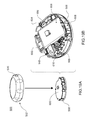
- FIGS. 55A-55B depict the locking ring assembly of the infusion pump assembly of FIG. 32 ;
- FIG. 56A-56C depict the locking ring assembly of the infusion pump assembly of FIG. 32 ;
- FIGS. 57-58 is an isometric view of an infusion pump assembly and a fill adapter
- FIGS. 59-64 are various views of the fill adapter of FIG. 57 ;
- FIG. 65 is an isometric view of another embodiment of a fill adapter
- FIGS. 66-67 depict an infusion pump assembly and another embodiment of a fill adapter
- FIGS. 68-74 are various views of the fill adapter of FIG. 66 ;
- FIGS. 75-80 depict various views of an embodiment of a battery charger
- FIGS. 81-89B depict various embodiments of battery chargers/docking stations
- FIGS. 90A-90C are various views of a volume sensor assembly included within the infusion pump assembly of FIG. 1 ;
- FIGS. 91A-91I are various views of a volume sensor assembly included within the infusion pump assembly of FIG. 1 ;
- FIGS. 92A-92I are various views of a volume sensor assembly included within the infusion pump assembly of FIG. 1 ;
- FIGS. 93A-93I are various views of a volume sensor assembly included within the infusion pump assembly of FIG. 1 ;
- FIGS. 94A-94F are various views of a volume sensor assembly included within the infusion pump assembly of FIG. 1 ;
- FIG. 95 is an exploded view of a volume sensor assembly included within the infusion pump assembly of FIG. 1 ;
- FIG. 96 is a diagrammatic view of a volume sensor assembly included within the infusion pump assembly of FIG. 1 ;
- FIG. 97 is a two-dimensional graph of a performance characteristic of the volume sensor assembly of FIG. 96 ;
- FIG. 98 is a two-dimensional graph of a performance characteristic of the volume sensor assembly of FIG. 96 ;
- FIG. 99 is a two-dimensional graph of a performance characteristic of the volume sensor assembly of FIG. 96 ;
- FIG. 100 is a diagrammatic view of a volume sensor assembly included within the infusion pump assembly of FIG. 1 ;
- FIG. 101 is a two-dimensional graph of a performance characteristic of the volume sensor assembly of FIG. 100 ;
- FIG. 102 is a two-dimensional graph of a performance characteristic of the volume sensor assembly of FIG. 100 ;
- FIG. 103 is a diagrammatic view of a volume sensor assembly included within the infusion pump assembly of FIG. 1 ;
- FIG. 104 is a two-dimensional graph of a performance characteristic of a volume sensor assembly included within the infusion pump assembly of FIG. 1 ;
- FIG. 105 is a two-dimensional graph of a performance characteristic of a volume sensor assembly included within the infusion pump assembly of FIG. 1 ;
- FIG. 106 is a two-dimensional graph of a performance characteristic of a volume sensor assembly included within the infusion pump assembly of FIG. 1 ;
- FIG. 107 is a two-dimensional graph of a performance characteristic of a volume sensor assembly included within the infusion pump assembly of FIG. 1 ;
- FIG. 108 is a two-dimensional graph of a performance characteristic of a volume sensor assembly included within the infusion pump assembly of FIG. 1 ;
- FIG. 109 is a diagrammatic view of a control model for a volume sensor assembly included within the infusion pump assembly of FIG. 1 ;
- FIG. 110 is a diagrammatic view of an electrical control assembly for the volume sensor assembly included within the infusion pump assembly of FIG. 1 ;
- FIG. 111 is a diagrammatic view of a volume controller for the volume sensor assembly included within the infusion pump assembly of FIG. 1 ;
- FIG. 112 is a diagrammatic view of a feed forward controller of the volume controller of FIG. 111 ;
- FIGS. 113-114 diagrammatically depicts an implementation of an SMA controller of the volume controller of FIG. 111 ;
- FIG. 114A-114B is an alternate implementation of an SMA controller
- FIG. 115 diagrammatically depicts a multi-processor control configuration that may be included within the infusion pump assembly of FIG. 1 ;
- FIG. 116 is a diagrammatic view of a multi-processor control configuration that may be included within the infusion pump assembly of FIG. 1 ;
- FIG. 117A-117B diagrammatically depicts multi-processor functionality
- FIG. 118 diagrammatically depicts multi-processor functionality
- FIG. 119 diagrammatically depicts multi-processor functionality
- FIGS. 120A-120E graphically depicts various software layers
- FIG. 121 diagrammatically depicts a volume sensor assembly included within the infusion pump assembly of FIG. 1 ;
- FIG. 122 diagrammatically depicts an inter-connection of the various systems of the infusion pump assembly of FIG. 1 ;
- FIG. 123 diagrammatically depicts basal—bolus infusion events
- FIG. 124 diagrammatically depicts basal—bolus infusion events
- FIG. 125A-125G depicts a hierarchial state machine
- FIG. 126A-126M depicts a hierarchial state machine
- FIG. 127 is an exemplary diagram of a split ring resonator antenna
- FIG. 128 is an exemplary diagram of a medical device configured to utilize a split ring resonator antenna
- FIG. 129 is an exemplary diagram of a split ring resonator antenna and transmission line from a medical infusion device
- FIG. 130 is a graph of the return loss of a split ring resonator antenna prior to contact with human skin
- FIG. 130A is a graph of the return loss of a split ring resonator antenna during contact with human skin
- FIG. 131 is an exemplary diagram of a split ring resonator antenna integrated into a device which operates within close proximity to dielectric material;
- FIG. 132 is a diagram of the dimensions of the inner and outer portion of the exemplary embodiment.
- FIG. 133 is a graph of the return loss of a non-split ring resonator antenna prior to contact with human skin.
- FIG. 133A is a graph of the return loss of a non-split ring resonator antenna during contact with human skin.
- an infusion pump assembly 100 may include a reusable housing assembly 102 .
- Reusable housing assembly 102 may be constructed from any suitable material, such as a hard or rigid plastic, that will resist compression.
- suitable material such as a hard or rigid plastic
- use of durable materials and parts may improve quality and reduce costs by providing a reusable portion that lasts longer and is more durable, providing greater protection to components disposed therein.
- Reusable housing assembly 102 may include mechanical control assembly 104 having a pump assembly 106 and at least one valve assembly 108 .
- Reusable housing assembly 102 may also include electrical control assembly 110 configured to provide one or more control signals to mechanical control assembly 104 and effectuate the basal and/or bolus delivery of an infusible fluid to a user.
- Disposable housing assembly 114 may include valve assembly 108 which may be configured to control the flow of the infusible fluid through a fluid path.
- Reusable housing assembly 102 may also include pump assembly 106 which may be configured to pump the infusible fluid from the fluid path to the user.
- Electrical control assembly 110 may monitor and control the amount of infusible fluid that has been and/or is being pumped. For example, electrical control assembly 110 may receive signals from volume sensor assembly 148 and calculate the amount of infusible fluid that has just been dispensed and determine, based upon the dosage required by the user, whether enough infusible fluid has been dispensed. If enough infusible fluid has not been dispensed, electrical control assembly 110 may determine that more infusible fluid should be pumped. Electrical control assembly 110 may provide the appropriate signal to mechanical control assembly 104 so that any additional necessary dosage may be pumped or electrical control assembly 110 may provide the appropriate signal to mechanical control assembly 104 so that the additional dosage may be dispensed with the next dosage. Alternatively, if too much infusible fluid has been dispensed, electrical control assembly 110 may provide the appropriate signal to mechanical control assembly 104 so that less infusible fluid may be dispensed in the next dosage.
- Mechanical control assembly 104 may include at least one shape-memory actuator 112 .
- Pump assembly 106 and/or valve assembly 108 of mechanical control assembly 104 may be actuated by at least one shape-memory actuator, e.g., shape-memory actuator 112 , which may be a shape-memory wire in wire or spring configuration.
- Shape memory actuator 112 may be operably connected to and activated by electrical control assembly 110 , which may control the timing and the amount of heat and/or electrical energy used to actuate mechanical control assembly 104 .
- Shape memory actuator 112 may be, for example, a conductive shape-memory alloy wire that changes shape with temperature. The temperature of shape-memory actuator 112 may be changed with a heater, or more conveniently, by application of electrical energy.
- Shape memory actuator 112 may be a shape memory wire constructed of nickel/titanium alloy, such as NITINOLTM or FLEXINOL®.
- Infusion pump assembly 100 may include a volume sensor assembly 148 configured to monitor the amount of fluid infused by infusion pump assembly 100 .
- volume sensor assembly 148 may employ, for example, acoustic volume sensing.
- Acoustic volume measurement technology is the subject of U.S. Pat. Nos. 5,575,310 and 5,755,683 assigned to DEKA Products Limited Partnership, as well as U.S. patent application Publication Nos. US 2007/0228071 A1, US 2007/0219496 A1, US 2007/0219480 A1, US 2007/0219597 A1, the entire disclosures of all of which are incorporated herein by reference.
- Infusion pump assembly 100 may be configured so that the volume measurements produced by volume sensor assembly 148 may be used to control, through a feedback loop, the amount of infusible fluid that is infused into the user.
- Infusion pump assembly 100 may further include a disposable housing assembly 114 .
- disposable housing assembly 114 may be configured for a single use or for use for a specified period of time, e.g., three days or any other amount of time.
- Disposable housing assembly 114 may be configured such that any components in infusion pump assembly 100 that come in contact with the infusible fluid are disposed on and/or within disposable housing assembly 114 .
- a fluid path or channel including a reservoir may be positioned within disposable housing assembly 114 and may be configured for a single use or for a specified number of uses before disposal.
- the disposable nature of disposable housing assembly 114 may improve sanitation of infusion pump assembly 100 .
- disposable housing assembly 114 may be configured to releasably engage reusable housing assembly 102 , and includes a cavity 116 that has a reservoir 118 for receiving an infusible fluid (not shown), e.g., insulin. Such releasable engagement may be accomplished by a screw-on, a twist-lock or a compression fit configuration, for example.
- Disposable housing assembly 114 and/or reusable housing assembly 102 may include an alignment assembly configured to assist in aligning disposable housing assembly 114 and reusable housing assembly 102 for engagement in a specific orientation.
- base nub 120 and top nub 122 may be used as indicators of alignment and complete engagement.
- Cavity 116 may be at least partially formed by and integral to disposable housing assembly 114 .
- Cavity 116 may include a membrane assembly 124 for at least partially defining reservoir 118 .
- Reservoir 118 may be further defined by disposable housing assembly 114 , e.g., by a recess 126 formed in base portion 128 of disposable housing assembly 114 .
- membrane assembly 124 may be disposed over recess 126 and attached to base portion 128 , thereby forming reservoir 118 .
- Membrane assembly 124 may be attached to base portion 128 by conventional means, such as gluing, heat sealing, and/or compression fitting, such that a seal 130 is formed between membrane assembly 124 and base portion 128 .
- Membrane assembly 124 may be flexible and the space formed between membrane assembly 124 and recess 126 in base portion 128 may define reservoir 118 .
- Reservoir 118 may be non-pressurized and in fluid communication with a fluid path (not shown).
- Membrane assembly 124 may be at least partially collapsible and cavity 116 may include a vent assembly, thereby advantageously preventing the buildup of a vacuum in reservoir 118 as the infusible fluid is delivered from reservoir 118 to the fluid path.
- membrane assembly 124 is fully collapsible, thus allowing for the complete delivery of the infusible fluid.
- Cavity 116 may be configured to provide sufficient space to ensure there is always some air space even when reservoir 118 is filled with infusible fluid.
- membranes and reservoirs described herein may be made from materials including but not limited to silicone, NITRILE, and any other material having desired resilience and properties for functioning as described herein. Additionally, other structures could serve the same purpose.
- a partially collapsible non pressurized reservoir may advantageously prevent the buildup of air in the reservoir as the fluid in the reservoir is depleted. Air buildup in a vented reservoir could prevent fluid egress from the reservoir, especially if the system is tilted so that an air pocket intervenes between the fluid contained in the reservoir and the septum of the reservoir. Tilting of the system is expected during normal operation as a wearable device.
- Reservoir 118 may be conveniently sized to hold an insulin supply sufficient for delivery over one or more days.
- reservoir 118 may hold about 1.00 to 3.00 ml of insulin.
- a 3.00 ml insulin reservoir may correspond to approximately a three day supply for about 90% of potential users.
- reservoir 118 may be any size or shape and may be adapted to hold any amount of insulin or other infusible fluid.
- the size and shape of cavity 116 and reservoir 118 is related to the type of infusible fluid that cavity 116 and reservoir 118 are adapted to hold.
- Disposable housing assembly 114 may include a support member 132 ( FIG. 3 ) configured to prevent accidental compression of reservoir 118 . Compression of reservoir 118 may result in an unintentional dosage of infusible fluid being forced through the fluid path to the user.
- reusable housing assembly 102 and disposable housing assembly 114 may be constructed of a rigid material that is not easily compressible.
- support member 132 may be included within disposable housing assembly 114 to prevent compression of infusion pump assembly 100 and cavity 116 therein.
- Support member 132 may be a rigid projection from base portion 128 .
- support member 132 may be disposed within cavity 116 and may prevent compression of reservoir 118 .
- cavity 116 may be configured to provide sufficient space to ensure there is always some air space even when reservoir 118 is filled with infusible fluid. Accordingly, in the event that infusion pump assembly 100 is accidentally compressed, the infusible fluid may not be forced through cannula assembly 136 (e.g., shown in FIG. 9 ).
- Cavity 116 may include a septum assembly 146 ( FIG. 3 ) configured to allow reservoir 118 to be filled with the infusible fluid.
- Septum assembly 146 may be a conventional septum made from rubber or plastic and have a one-way fluid valve configured to allow a user to fill reservoir 118 from a syringe or other filling device.
- septum 146 may be located on the top of membrane assembly 124 .
- cavity 116 may include a support structure (e.g., support member 132 in FIG. 3 ) for supporting the area about the back side of the septum so as to maintain the integrity of the septum seal when a needle is introducing infusible fluid into cavity 116 .
- the support structure may be configured to support the septum while still allowing the introduction of the needle for introducing infusible fluid into cavity 116 .
- Infusion pump assembly 100 may include an overfill prevention assembly (not shown) that may e.g., protrude into cavity 116 and may e.g., prevent the overfilling of reservoir 118 .
- an overfill prevention assembly (not shown) that may e.g., protrude into cavity 116 and may e.g., prevent the overfilling of reservoir 118 .
- reservoir 118 may be configured to be filled a plurality of times.
- reservoir 118 may be refillable through septum assembly 146 .
- electronic control assembly 110 may monitor the fluid level of the infusible fluid in reservoir 118 . When the fluid level reaches a low point, electronic control assembly 110 may provide a signal, such as a light or a vibration, to the user that reservoir 118 needs to be refilled.
- a syringe, or other filling device may be used to fill reservoir 118 through septum 146 .
- Reservoir 118 may be configured to be filled a single time.
- a refill prevention assembly (not shown) may be utilized to prevent the refilling of reservoir 118 , such that disposable housing assembly 114 may only be used once.
- the refill prevention assembly (not shown) may be a mechanical device or an electro-mechanical device.
- insertion of a syringe into septum assembly 146 for filling reservoir 118 may trigger a shutter to close over septum 146 after a single filling, thus preventing future access to septum 146 .
- a sensor may indicate to electronic control assembly 110 that reservoir 118 has been filled once and may trigger a shutter to close over septum 146 after a single filling, thus preventing future access to septum 146 .
- Other means of preventing refilling may be utilized and are considered to be within the scope of this disclosure.
- disposable housing assembly 114 may include septum assembly 146 that may be configured to allow reservoir 118 to be filled with the infusible fluid.
- Septum assembly 146 may be a conventional septum made from rubber or any other material that may function as a septum, or, in other embodiments, septum assembly 146 may be, but is not limited to, a plastic, or other material, one-way fluid valve.
- septum assembly 146 is configured to allow a user to fill reservoir 118 from a syringe or other filling device.
- Disposable housing assembly 114 may include a septum access assembly that may be configured to limit the number of times that the user may refill reservoir 118 .
- septum access assembly 152 may include shutter assembly 154 that may be held in an “open” position by a tab assembly 156 that is configured to fit within a slot assembly 158 .
- shutter assembly 154 may be displaced downward, resulting in tab assembly 156 disengaging from slot assembly 158 .
- spring assembly 162 may displace shutter assembly 154 in the direction of arrow 164 , resulting in septum 146 no longer being accessible to the user.
- septum access assembly 166 is shown in the “open” position.
- septum access assembly 166 includes shutter assembly 168 and spring assembly 170 .
- septum access assembly 172 may include shutter assembly 174 and spring assembly 176 .
- shutter assembly 172 may move to the “closed” position (e.g., which may prevent further access of septum 146 by the user)
- tab 178 may at least partially engage slot 180 a .
- Engagement between tab 178 and slot 180 a may lock shutter assembly 172 in the “closed” position to inhibit tampering and reopening of shutter assembly 172 .
- Spring tab 182 of shutter assembly 172 may bias tab 178 into engagement with slot 180 a.
- septum access assemblies may not be actuated linearly.
- septum access assembly 184 that includes shutter assembly 186 that is configured to pivot about axis 188 .
- septum 146 When positioned in the open position (as shown in FIG. 7A ), septum 146 may be accessible due to passage 190 (in shutter assembly 186 ) being aligned with passage 192 in e.g., a surface of disposable housing assembly 114 .
- passage 190 in shutter assembly 186
- passage 192 in e.g., a surface of disposable housing assembly 114 .
- septum access assemblies 166 , 172 upon penetrating septum 146 with filling syringe 160 (See FIG.
- shutter assembly 186 may be displaced in a clockwise fashion, resulting in passage 190 (in shutter assembly 186 ) no longer being aligned with passage 192 in e.g., a surface of disposable housing assembly 114 , thus preventing access to septum 146 .
- septum access assembly 194 includes shutter assembly 196 and spring assembly 198 that is configured to bias shutter assembly 196 in the direction of arrow 200 .
- Filling assembly 202 may be used to fill reservoir 118 .
- Filling assembly 202 may include shutter displacement assembly 204 that may be configured to displace shutter assembly 196 in the direction of arrow 206 , which in turn aligns passage 208 in shutter assembly 196 with septum 146 and passage 210 in septum access assembly 194 , thus allowing filling syringe assembly 212 to penetrate septum 146 and fill reservoir 118 .
- Infusion pump assembly 100 may include a sealing assembly 150 ( FIG. 3 ) configured to provide a seal between reusable housing assembly 102 and disposable housing assembly 114 .
- a sealing assembly 150 FIG. 3
- sealing assembly 150 may include an o-ring assembly (not shown).
- sealing assembly 150 may include an over molded seal assembly (not shown).
- sealing assembly 150 may be a watertight seal assembly and, thus, enable a user to wear infusion pump assembly 100 while swimming, bathing or exercising.
- infusion pump assembly 100 may include an external infusion set 134 configured to deliver the infusible fluid to a user.
- External infusion set 134 may be in fluid communication with cavity 118 , e.g. by way of the fluid path.
- External infusion set 134 may be disposed adjacent to infusion pump assembly 100 .
- external infusion set 134 may be configured for application remote from infusion pump assembly 100 , as discussed in greater detail below.
- External infusion set 134 may include a cannula assembly 136 , which may include a needle or a disposable cannula 138 , and tubing assembly 140 .
- Tubing assembly 140 may be in fluid communication with reservoir 118 , for example, by way of the fluid path, and with cannula assembly 138 for example, either directly or by way of a cannula interface 142 .
- External infusion set 134 may be a tethered infusion set, as discussed above regarding application remote from infusion pump assembly 100 .
- external infusion set 134 may be in fluid communication with infusion pump assembly 100 through tubing assembly 140 , which may be of any length desired by the user (e.g., 3-18 inches).
- tubing assembly 140 may be of any length desired by the user (e.g., 3-18 inches).
- infusion pump assembly 100 may be worn on the skin of a user with the use of adhesive patch 144
- the length of tubing assembly 140 may enable the user to alternatively wear infusion pump assembly 100 in a pocket. This may be beneficial to users whose skin is easily irritated by application of adhesive patch 144 .
- wearing and/or securing infusion pump assembly 100 in a pocket may be preferable for users engaged in physical activity.
- a hook and loop fastener system (e.g. such as hook and loop fastener systems offered by Velcro USA Inc. of Manchester, N.H.) may be utilized to allow for easy attachment/removal of an infusion pump assembly (e.g., infusion pump assembly 100 ) from the user.
- adhesive patch 144 may be attached to the skin of the user and may include an outward facing hook or loop surface.
- the lower surface of disposable housing assembly 114 may include a complementary hook or loop surface.
- the strength of the hook and loop connection may be stronger than the strength of the adhesive to skin connection. Accordingly, various hook and loop surface patterns may be utilized to regulate the strength of the hook and loop connection.
- hook and loop surface patterns five examples are shown. Assume for illustrative purposes that the entire lower surface of disposable housing assembly 114 is covered in a “loop” material. Accordingly, the strength of the hook and loop connection may be regulated by varying the pattern (i.e., amount) of the “hook” material present on the surface of adhesive patch 144 . Examples of such patterns may include but are not limited to: a singular outer circle 220 of “hook” material (as shown in FIG. 10A ); a plurality of concentric circles 222 , 224 of “hook” material (as shown in FIG. 10B ); a plurality of radial spokes 226 of “hook” material (as shown in FIG.
- infusion pump assembly 100 ′ may be configured via a remote control assembly 300 .
- infusion pump assembly 100 ′ may include telemetry circuitry (not shown) that allows for communication (e.g., wired or wireless) between infusion pump assembly 100 ′ and e.g., remote control assembly 300 , thus allowing remote control assembly 300 to remotely control infusion pump assembly 100 ′.
- Remote control assembly 300 (which may also include telemetry circuitry (not shown) and may be capable of communicating with infusion pump assembly 100 ′) may include display assembly 302 and input assembly 304 .
- Input assembly 304 may include slider assembly 306 and switch assemblies 308 , 310 .
- the input assembly may include a jog wheel, a plurality of switch assemblies, or the like.
- Remote control assembly 300 may include the ability to pre-program basal rates, bolus alarms, delivery limitations, and allow the user to view history and to establish user preferences. Remote control assembly 300 may also include a glucose strip reader.
- remote control assembly 300 may provide instructions to infusion pump assembly 100 ′ via wireless communication channel 312 established between remote control assembly 300 and infusion pump assembly 100 ′. Accordingly, the user may use remote control assembly 300 to program/configure infusion pump assembly 100 ′. Some or all of the communication between remote control assembly 300 and infusion pump assembly 100 ′ may be encrypted to provide an enhanced level of security.
- infusion pump assembly 100 , 100 ′ may include electrical control assembly 110 that may include one or more electrical components.
- electrical control assembly 110 may include a plurality of data processors (e.g. a supervisor processor and a command processor) and a radio processor for allowing infusion pump assembly 100 , 100 ′ to communicate with remote control assembly 300 .
- remote control assembly 300 may include one or more electrical components, examples of which may include but are not limited to a command processor and a radio processor for allowing remote control assembly 300 to communicate with infusion pump assembly 100 , 100 ′.
- a command processor and a radio processor for allowing remote control assembly 300 to communicate with infusion pump assembly 100 , 100 ′.
- FIG. 11B A high-level diagrammatic view of one example of such a system is shown in FIG. 11B .
- Each of these electrical components may be manufactured from a different component provider and, therefore, may utilize native (i.e. unique) communication commands. Accordingly, through the use of a standardized communication protocol, efficient communication between such disparate components may be accomplished.
- PCGP may be a flexible extendable software module that may be used on the processors within infusion pump assembly 100 , 100 ′ and remote control assembly 300 to build and route packets.
- PCGP may abstract the various interfaces and may provide a unified application programming interface (API) to the various applications being executed on each processor.
- API application programming interface
- PCGP may also provide an adaptable interface to the various drivers.
- PCGP may have the conceptual structure illustrated in FIG. 11C for any given processor.
- PCGP may ensure data integrity by utilizing cyclic redundancy checks (CRCs). PCGP may also provide guaranteed delivery status. For example, all new messages should have a reply. If such a reply isn't sent back in time, the message may time out and PCGP may generate a negative acknowledge reply message for the application (i.e., a NACK). Accordingly, the message-reply protocol may let the application know whether the application should retry sending a message.
- CRCs cyclic redundancy checks
- PCGP may also limit the number of messages in-flight from a given node, and may be coupled with a flow-control mechanism at the driver level to provide a deterministic approach to message delivery and may let individual nodes have different quantities of buffers without dropping packets. As a node runs out of buffers, drivers may provide back pressure to other nodes and prevent sending of new messages.
- PCGP may use a shared buffer pool strategy to minimize data copies, and may avoid mutual exclusions, which may have a small affect on the API used to send/receive messages to the application, and a larger affect on the drivers.
- PCGP may use a “Bridge” base class that provides routing and buffer ownership. The main PCGP class may be sub-classed from the bridge base class. Drivers may either be derived from a bridge class, or talk to or own a derived bridge class.
- PCGP may be designed to work in an embedded environment with or without an operating system by using a semaphore to protect shared data such that some calls can be re-entrant and run on a multiple threads.
- FIG. 11D One illustrative example of such an implementation is shown in FIG. 11D .
- PCGP may operate the same way in both environments, but there may be versions of the call for specific processor types (e.g., the ARM 9/OS version). So while the functionality may be the same, there may be an operating system abstraction layer with slightly different calls tailored for e.g., the ARM 9 Nucleus OS environment.
- PCGP may:
- Each software object may ask the buffer manager for the next buffer to use, and may then give that buffer to another object.
- Buffers may pass from one exclusive owner to another autonomicly, and queues may occur automatically by ordering buffers by sequence number.
- the buffer may be recycled (e.g., object attempts to give the buffer to itself, or frees it for the buffer manager to re-allocate later). Accordingly, data generally doesn't need to be copied, and routing simply writes over the buffer ownership byte.
- PCGP may provide various benefits, examples of which may include but are not limited to:
- the PCGP may build the packet quickly and may insert it into the buffer management system.
- a call to “packetProcessor” may apply protocol rules and may give the messages to the drivers/application.
- PCGP may:
- PCGP may work by doing all of the main work on one thread to avoid mutual exclusions, and to avoid doing considerable work on the send/reply or driver calls.
- the “packetProcessor” call may have to apply protocol rules to replies, new sent messages, and received messages. Reply messages may simply get routed, but new messages and received messages may have rules for routing the messages. In each case, the software may loop while a message of the right type is available to apply protocol rules until it cannot process the packets.
- Sending a new message may conform to the following rules:
- Receiving a message may conform to the following rules:
- PCGP may be configured such that:
- the communication system may have a limited number of buffers.
- drivers may stop receiving new packets and the application may be told that the application cannot send new packets.
- the application may try to perform one or more procedures, examples of which may include but are not limited to:
- the RX driver may be asked to receive a message from the other side of the interface.
- the RX driver may ask the buffer manager if there is an available buffer for storing a new message. The driver may then ask for a buffer pointer and may start filling the buffer with received data.
- the RX driver may call a function to route the packet. The route function may examine the destination byte in the packet header and may change the owner to either the other driver, or the application, or may detect that the packet is bad and may drop the packet by freeing the buffer.
- PCGP RX overhead may consist of asking for the next available buffer and calling the route function.
- code that performs such a function is as follows:
- a driver may perform a TX by asking the buffer manager for the pointer to the next buffer to send.
- the TX driver may then ask the other side of the interface if it can accept a packet. If the other side denies the packet, the TX driver may do nothing to the buffer, as its status has not changed. Otherwise, the driver may send the packet and may recycle/free the buffer.
- An example of code that performs such a function is as follows:
- asking for the nextBuffer may call the BufferManager::first(uint8 owner) function that may scan for buffers to free. Accordingly, full TX buffers with no hope of making a timeout may be freed on the thread that owns the buffer. A bridge that is doing TX (i.e., while looking for the next TX buffer) may free all of the TX buffers that are expired before receiving the next TX buffer for processing.
- buffers marked free may be transferred to the drivers to receive new packets, or to PCGP to receive new payloads for TX. Allocation from “free” may be done by the “packetProcessor” function. The number of sends and receives between “packetProcessor” calls may dictate how many LT_Driver_RX, GT_Driver_RX and PCGP_Free buffers need to be allocated.
- LT_Driver may represent drivers that handle addresses that are less than the node address.
- GT_Driver may represent drivers that handle addresses that are greater than the node address.
- the driver may put the data into an RX buffer that gets handed to the router.
- the router may then reassign the buffer to PCGP_Receive or to the other driver's TX (not shown). If the buffer contains obviously invalid data, the buffer may transition to free.
- the driver may discover the buffer is TX and may send the message. After sending the message, the buffer may immediately become an RX buffer if the driver was low in RX buffers, or the buffer may be freed for re-allocation.
- PCGP may process all buffers that the router marked as PCGP_Receive. At this point, data may be acted upon, so the CRC and other data items may be checked. If the data is corrupted, a statistic may be incremented and the buffer may be freed. Otherwise, the buffer may be marked as owned by the application. Buffers marked as owned by the application may be either recycled for the use of PCGP or freed for reallocation by the buffer manager.
- the application When the application wants to send a new message, it may be done in a re-entrant friendly/mutual exclusion manner. If the buffer may be allocated, PCGP may mark the buffer as busy. Once marked busy, no other thread calling the send or reply functions may grab this buffer, as it is owned by this function call's invocation. The remainder of the process of error checking and building the message may be done outside the isolated race condition mutual exclusion guarded code.
- the buffer may either transition to free or may become a valid filled CRC-checked buffer and passed to the router. These buffers may not be routed immediately and may be queued so that messages can be sent later (assuming that protocol rules allow).
- Reply messages may be marked differently than new send messages because reply messages may be routed with a higher priority than regular send messages and reply messages may have no rules limiting how many/when they can be sent.
- PCGP was designed to work with flow control, and flow control may negotiate the transfer of messages from one node to another node so that a buffer is never dropped because the other side of an interface lacks a buffer (which may cause back pressure on the sending node).
- Flow control may be apart of the shared buffer format.
- the first two bytes may be reserved for the driver so that the driver never needs to shift the packet bytes.
- Two bytes may be used so that one byte is the DMA length ⁇ 1, and the second byte is to control the flow of messages.
- These same two bytes may be synchronizing bytes if a PCGP message is transmitted over RS232.
- the packet When a packet is “in-flight”, the packet may be in the process of being sent by a driver on the way to its destination, being processed by the destination, or being sent back as a response.
- Typical delays are as follows:
- messages tend to complete the round trip either: quickly (e.g., ⁇ 50 ms); slowly (e.g., one or more seconds); or not at all.
- PCGP may use two different times (set at initialization) for all timeouts, one for when the RF link is in fast heartbeat mode, and another for when the RF link is in slow mode. If a message is in-flight and the link status changes from fast to slow, the timeout may be adjusted and the difference between fast and slow may be added to the time-to-live counter for the packet. No additional transitions back and forth may affect the time-to-live time for the message.
- a second timeout may be twice as long as the slow timeout that is used to monitor buffer allocation inside PCGP. Accordingly, if a message is “stuck” inside a driver and hasn't been sent due to e.g., flow control or hardware damage, the buffer may be freed by the buffer manager, resulting in the buffer being dropped. For a “new” message, this may mean that the packet already timed out and the application was already given a reply saying the message wasn't delivered, resulting in the buffer being freed. Since the driver polls the buffer manager for buffers that need to be sent, the buffer is freed up so that a message that could be sent is handed to the driver the next time that it unblocks. For a reply message, the reply may simply get dropped and the sending node may time out.
- the PCGP messaging system may pass messages that contain header information and payload.
- the header may be a set of data items in a call signature.
- Drivers may insert bytes either into the PCGP packet or before the PCGP packet such:
- PCGP may not be an event driven software design, but may be used in event driven architectures by how the sub-classes are written. Data may be exchanged between the classes conceptually (as shown in FIG. 11M-11N ).
- Some event model in the driver may wake the driver, may receive a message and may pass the message through the bridge into the buffer manager that routes the message to new owner of the new message (through a bridge to either a driver or PCGP).
- the following illustrative example shows how the PCGP event model may work with Nucleus to wakeup the PCGP task after every message send, reply, or decTimeout that generated a NACK:
- class PcgpOS public Pcgp ⁇ virtual void schedulePacketProcessor(void) ⁇ OS_EventGrp_Set(g_RCVEvGrps[EVG_RF_TASK].pEvgHandle, RfRadioTxEvent, OS_EV_OR_NO_CLEAR); ⁇ ⁇
- PCGP PCGP
- PCGP may be designed to run in multiple processing environments. Most parameters may be run time configured because it facilitates testing, and any run time fine tuning for performance. Other parameters may be compile time e.g., anything that alters memory allocation must be done statically at compile time.
- the CRC may be used to ensure data integrity. If a CRC is invalid, it may not be delivered to the application and the CRC error may be tracked. The message may eventually timeout and may be retried by the originator.
- the Stop Bolus Command is an example of such a command. This may be mitigated by the Request/Action sequence of messages which may be required by the application to change therapy.
- the Controller may receive a matching command from the Pump application to consider the message delivered.
- DEKA may provide a reference way of interfacing PCGP into the Nucleus OS system on the ARM 9 (as shown in FIG. 110 ).
- the pcgpOS.cpp file may instantiate a PCGP node instance (Pcgp, a Bridge, etc.) and may provide through pcgpOS.h a ‘C’ linkable set of function calls that provide a ‘C’ language interface to the C++ code. This may simplify the ‘C’ code as the objects acted upon are implicit.
- SPI flow control may prevent data from being sent if the receiving side does not currently have an empty buffer to place the packet. This may be accomplished by asking for permission to send and waiting for a response indicating that you have been cleared to do so. There may also be a way to tell the other side that there are currently no free buffers and the transfer should be attempted at a later time.
- All transmission may begin with a length byte that indicates the number of bytes to be sent, not including the length byte itself. Following the length may be a single byte indicating the command being sent.
- the actual transmission of a packet may be the length of packet plus one for the command byte, followed by the command byte for a message appended and finally the packet itself.
- FlowControl line may be added to the traditional four SPI signals.
- the purpose of this line is to allow the protocol to run as quickly as possible without a need for preset delays. It also allows the slave processor to tell the master processor that it has a packet waiting to be sent, thus eliminating the need for the master processor to poll the slave processor for status.
- S_PREPARING_FOR_RX 0xA1 Slave is prepare the dma to receive a packet S_RX_BUFF_FULL 0xA2 Slave is currently out of RX buffers, retry later S_MSG_APPENDED 0xA3 Slave is sending a packet S_ERROR 0xA4 An Error condition has been encountered
- the slave processor may notify the master processor (by asserting the FlowControl line) that it has a pending packet that is waiting to be sent. Doing so may result in an IRQ on the master processor at which time the master processor may decide when to go retrieve the message from the slave processor. Retrieving the packet may be delayed at the discretion of the master processor, and the master processor may even decide to attempt to send a packet to the slave processor before retrieving from the slave processor.
- the master processor may begin the retrieval by sending the slave processor M_CTS commands; this shall be repeated until the slave processor responds by sending the S_MSG_APPENDED command along with the packet itself.
- the FlowControl line may be cleared after the packet has been sent. If a M_CTS command is received by the slave processor when one is not expected, the M_CTS command may be ignored.
- the master processor may initiate the transfer by sending a M_RTS command.
- M_RTS command if the slave processor currently has a send packet pending, the slave processor will lower the FlowControl line so that it may be re-used as a Cleared To Send signal.
- the slave processor may then tell the master processor that it is in the process of preparing the SPI DMA to receive the packet, during which time the master processor may stop clocking bytes onto the bus and may allow the slave processor to finish preparing for the receive.
- the slave processor may then indicate it is ready to receive the full packet by raising the FlowControl line (which is now used as the CTS signal). Upon receiving the CTS signal, the master processor may proceed to send the M_MSG_APPENDED command along with the packet itself.
- the slave processor may lower the FlowControl line. If a packet was pending at the start of the transfer, or a send occurred on the slave processor when the packet was being received, the slave processor may reassert the FlowControl line now indicating that it has a pending packet.
- infusion pump assembly 100 , 100 ′ may include switch assembly 318 coupled to electrical control assembly 110 ( FIG. 3 ) that may allow a user (not shown) to perform at least one, and in some embodiments, a plurality of tasks.
- a user not shown
- One illustrative example of such a task is the administration of a bolus dose of the infusible fluid (e.g., insulin) without the use of a display assembly.
- Remote control assembly 300 may allow the user to enable/disable/configure infusion pump assembly 100 , 100 ′ to administer the bolus dose of insulin.
- slider assembly 306 may be configured, at least in part, to enable the user to manipulate the menu-based information rendered on display assembly 302 .
- An example of slider assembly 306 may include a capacitive slider assembly, which may be implemented using a CY8C21434-24LFXI PSOC offered by Cypress Semiconductor of San Jose, Calif., the design an operation of which are described within the “CSD User Module” published by Cypress Semiconductor.
- the user may slide their finger in the direction of arrow 314 , resulting in the highlighted portion of the information included within main menu 350 (shown in FIG. 12A ) rendered on display assembly 302 scrolling upward.
- the user may slide their finger in the direction of arrow 316 , resulting in the highlighted portion of the information included within main menu 350 rendered on display assembly 302 scrolling downward.
- Slider assembly 306 may be configured so that the rate at which e.g. the highlighted portion of main menu 350 scrolls “upward” or “downward” varies depending upon the displacement of the finger of the user with respect to point of origin 320 . Therefore, if the user wishes to quickly scroll “upward”, the user may position their finger near the top of slider assembly 306 . Likewise, if the user wishes to quickly scroll “downward”, the user may position their finger near the bottom of slider assembly 306 . Additionally, if the user wishes to slowly scroll “upward”, the user may position their finger slightly “upward” with respect to point of origin 320 Further, if the user wishes to slowly scroll “downward”, the user may position their finger slightly “downward” with respect to point of origin 320 . Once the appropriate menu item is highlighted, the user may select the highlighted menu item via one or more switch assemblies 308 , 310 .
- infusion pump assembly 100 , 100 ′ is an insulin pump and the user wishes to configure infusion pump assembly 100 , 100 ′ so that when switch assembly 318 is depressed by the user, a 0.20 unit bolus dose of insulin is administered.
- the user may use slider assembly 306 to highlight “Bolus” within main menu 350 rendered on display assembly 302 .
- the user may then use switch assembly 308 to select “Bolus”.
- processing logic (not shown) within remote control assembly 300 may then render submenu 352 on display assembly 302 (as shown in FIG. 12B ).
- the user may then use slider assembly 306 to highlight “Manual Bolus” within submenu 352 , which may be selected using switch assembly 308 .
- Processing logic (not shown) within remote control assembly 300 may then render submenu 354 on display assembly 302 (as shown in FIG. 12C ).
- the user may then use slider assembly 306 to highlight “Bolus: 0.0 Units” within submenu 354 , which may be selected using switch assembly 308 .
- Processing logic (not shown) within remote control assembly 300 may then render submenu 356 on display assembly 302 (as shown in FIG. 12D ).
- the user may then use slider assembly 306 to adjust the “Bolus” insulin amount to “0.20 units”, which may be selected using switch assembly 308 .
- Processing logic (not shown) within remote control assembly 300 may then render submenu 358 on display assembly 302 (as shown in FIG. 12E ).
- the user 14 may then use slider assembly 306 to highlight “Confirm”, which may be selected using switch assembly 308 .
- Processing logic (not shown) within remote control assembly 300 may then generate the appropriate signals that may be sent to the above-described telemetry circuitry (not shown) included within remote control assembly 300 .
- the telemetry circuitry (not shown) included within the remote control assembly may then transmit, via wireless communication channel 312 established between remote control assembly 300 and infusion pump assembly 100 ′, the appropriate configuration commands to configure infusion pump assembly 100 ′ so that whenever switch assembly 318 is depressed by the user, a 0.20 unit bolus dose of insulin is administered.
- processing logic within remote control assembly 300 may once again render submenu 350 on display assembly 302 (as shown in FIG. 12F ).
- the user may depress switch assembly 318 of infusion pump assembly 100 ′ to administer the above-described 0.20 unit bolus dose of insulin.
- the user may define a quantity of insulin to be administered each time that the user depresses switch assembly 318 . While this particular example specifies that a single depression of switch assembly 318 is equivalent to 0.20 units of insulin, this is for illustrative purposes only and is not intended to be a limitation of this disclosure, as other values (e.g. 1.00 units of insulin per depression) are equally applicable.
- the user wishes to administer a 2.00 unit bolus dose of insulin.
- the user may be required to press and hold switch assembly 318 for a defined period of time (e.g. five seconds), at which point infusion pump assembly 100 , 100 ′ may generate an audible signal indicating to the user that infusion pump assembly 100 , 100 ′ is ready to administer a bolus does of insulin via switch assembly 318 .
- the user may depress switch assembly 318 ten times (i.e., 2.00 units is ten 0.20 unit doses).
- infusion pump assembly 100 , 100 ′ may provide on audible response to the user via an internal speaker/sound generation device (not shown). Accordingly, the user may depress switch assembly 318 the first time and infusion pump assembly 100 , 100 ′ may generate a confirmation beep in response, thus indicating to the user that infusion pump assembly 100 , 100 ′ received the command for (in this particular example) 0.20 units of insulin. As the desired bolus dose is 2.00 units of insulin, the user may repeat this procedure nine more times in order to effectuate a bolus dose of 2.00 units, wherein infusion pump assembly 100 , 100 ′ generates a confirmation beep after each depression of switch assembly 318 .
- infusion pump assemblies 100 , 100 ′ are described as providing one beep after each time the user depresses switch assembly 318 , this is for illustrative purposes only and is not intended to be a limitation of this disclosure.
- infusion pump assembly 100 , 100 ′ may be configured to provide a single beep for each defined quantity of insulin.
- a single depression of switch assembly 318 may be equivalent to 0.20 units of insulin.
- infusion pump assembly 100 , 100 ′ may be configured to provide a single beep for each 0.10 units of insulin.
- infusion pump assembly 100 , 100 ′ may provide the user with two beeps (i.e. one for each 0.10 units of insulin).
- infusion pump assembly 100 , 100 ′ may simply wait for infusion pump assembly 100 , 100 ′ to acknowledge receipt of the instructions to administer a 2.00 unit bolus dose of insulin (as opposed to the confirmation beep received at each depression of switch assembly 318 ). Once a defined period of time (e.g., two seconds) passes, infusion pump assembly 100 , 100 ′ may provide an audible confirmation to the user concerning the quantity of units to be administered via the bolus insulin dose that the user just requested.
- a defined period of time e.g., two seconds
- infusion pump assembly 100 , 100 ′ was programmed by the user so that a single depression of switch assembly 318 is equivalent to 0.20 units of insulin, infusion pump assembly 100 , 100 ′ may beep ten times (i.e., 2.00 units is ten 0.20 unit doses).
- infusion pump assembly 100 , 100 ′ may provide a multifrequency audible confirmation. For example and continuing with the above-stated example in which ten beeps are to be provided to the user, infusion pump assembly 100 , 100 ′ may group the beeps into groups of five (to facilitate easier counting by the user) and the beeps within each group of five may be rendered by infusion pump assembly 100 , 100 ′ so that each subsequent beep has a higher frequency than the preceding beep (in a manner similar to a musical scale).
- infusion pump assembly 100 , 100 ′ may render a 1,000 Hz beep, followed by an 1,100 Hz beep, followed by a 1,200 Hz beep, followed by a 1,300 Hz beep, followed by a 1,400 Hz beep (thus completing a group of five beeps), followed by a short pause, and then a 1,000 Hz beep, followed by an 1,100 Hz beep, followed by a 1,200 Hz beep, followed by a 1,300 Hz beep, followed by a 1,400 Hz beep (thus completing the second group of five beeps).
- the multifrequency audible confirmation may utilize various numbers of tones incrementing in frequency.
- an embodiment may utilize twenty different tones incrementing in frequency.
- the number of tones should not be construed as a limitation of the present disclosure as number of tones may vary according to design criteria and user need.
- infusion pump assembly 100 , 100 ′ completes the rendering of the multifrequency audible confirmation (i.e. the ten beeps described above), the user may, within a defined period of time (e.g. two seconds), depress switch assembly 318 to provide a confirmation signal to infusion pump assembly 100 , 100 ′, indicating that the multifrequency audible confirmation was accurate and indicative of the size of the bolus dose of insulin to be administered (i.e. 2.00 units).
- infusion pump assembly 100 , 100 ′ may render a “confirmation received” audible tone and effectuate the delivery of (in this particular example) the 2.00 unit bolus dose of insulin.
- infusion pump assembly 100 , 100 ′ may render a “confirmation failed” audible tone and will not effectuate the delivery of the bolus dose of insulin. Accordingly, if the multifrequency audible confirmation was not accurate/indicative of the size of the bolus dose of insulin to be administered, the user may simply not provide the above-described confirmation signal, thereby canceling the delivery of the bolus dose of insulin.
- infusion pump assembly 100 ′ may be used to communicate with a remote control assembly 300 .
- remote control assembly 300 may routinely contact each other to ensure that the two devices are still in communication with each other.
- infusion pump assembly 100 ′ may “ping” remote control assembly 300 to ensure that remote control assembly 300 is present and active.
- remote control assembly 300 may “ping” infusion pump assembly 100 ′ to ensure that infusion pump assembly 100 ′ is still present and active.
- infusion pump assembly 100 ′ and remote control assembly 300 may sound a “separation” alarm.
- the assembly that is unable to establish communication may sound a “separation” alarm.
- remote control assembly 300 is left in the car of the user, while infusion pump assembly 100 ′ is in the pocket of the user. Accordingly and after a defined period of time, infusion pump assembly 100 ′ may begin sounding the “separation” alarm, indicating that communication with remote control assembly 300 cannot be established.
- switch assembly 318 the user may acknowledge/silence this “separation” alarm.
- infusion pump assembly 100 ′ may store information concerning the administered bolus insulin dose within a log file (not shown) stored within infusion pump assembly 100 ′. This log file (not shown) may be stored within nonvolatile memory (not shown) included within infusion pump assembly 100 ′.
- infusion pump assembly 100 ′ may provide the information concerning the administered bolus insulin dose stored within the log file (not shown) of infusion pump assembly 100 ′ to remote control assembly 300 .
- the user may configure infusion pump assembly 100 ′ and remote control assembly 300 to be in “separation” mode, thus eliminating the occurrence of the above-described “separation” alarms.
- the devices may continue to “ping” each other so that when they come back into communication with each other, infusion pump assembly 100 ′ and remote control assembly 300 may automatically exit “separation” mode.
- infusion pump assembly 100 ′ and remote control assembly 300 may configure infusion pump assembly 100 ′ and remote control assembly 300 to be in “airplane” mode, in which each of infusion pump assembly 100 ′ and remote control assembly 300 suspend any and all data transmissions. While in “airplane” mode, infusion pump assembly 100 ′ and remote control assembly 300 may or may not continue to receive data.
- Switch assembly 318 may be used to perform additional functions, such as: checking the battery life of reusable housing assembly 102 ; pairing reusable housing assembly 102 with remote control assembly 300 ; and aborting the administration of a bolus does of infusible fluid.
- Reusable housing assembly 102 may include a rechargeable battery assembly that may be capable of powering infusion pump assembly 100 , 100 ′ for approximately three days (when fully charged). Such a rechargeable battery assembly may have a usable life of a predetermined number of usable hours, for example, or years, or other predetermined length of usage. However, the predetermined life may depend on many factors, including but not limited to, one or more of the following: climate, daily usage, and number of recharges. Whenever reusable housing assembly 102 is disconnected from disposable housing assembly 114 , infusion pump assembly 100 , 100 ′ may perform a battery check on the above-described rechargeable battery assembly whenever switch assembly 318 is depressed for a defined period of time (e.g. in excess of two seconds).
- a defined period of time e.g. in excess of two seconds.
- infusion pump assembly 100 , 100 ′ may render a “battery pass” tone.
- infusion pump assembly 100 , 100 ′ may render a “battery fail” tone.
- Infusion pump assembly 100 , 100 ′ may include components and/or circuitry to determine whether reusable housing assembly 102 is disconnected from disposable housing assembly 114 .
- infusion pump assembly 100 ′ may be used to communicate with remote control assembly 300 .
- a paring process may be performed.
- one or more infusion pump assemblies e.g. infusion pump assembly 100 ′
- remote control assembly 300 may be configured to communicate with one or more infusion pump assemblies (e.g. infusion pump assembly 100 ′).
- the serial numbers of the infusion pump assemblies e.g.
- infusion pump assembly 100 ′ may be recorded within a pairing file (not shown) included within remote control assembly 300 and the serial number of remote control assembly 300 may be recorded within a pairing file (not shown) included within the infusion pump assemblies (e.g. infusion pump assembly 100 ′).
- the user may simultaneously hold down one or more switch assemblies on both remote control assembly 300 and infusion pump assembly 100 ′.
- the user may simultaneously hold down switch assembly 310 included within remote control assembly 300 and switch assembly 318 included within infusion pump assembly 100 ′ for a defined period exceeding e.g. five seconds. Once this defined period is reached, one or more of remote control assembly 300 and infusion pump assembly 100 ′ may generate an audible signal indicating that the above-described pairing procedure has been effectuated.
- the user may uncouple reusable housing assembly 102 from disposable housing assembly 114 .
- the user may uncouple reusable housing assembly 102 from disposable housing assembly 114 .
- the user may enter pairing mode via input assembly 304 of remote control assembly 300 .
- the user may enter pairing mode on remote control assembly 300 via the above-described menuing system in combination with e.g., switch assembly 310 .
- the user may be prompted on display assembly 302 of remote control assembly 300 to depress and hold switch assembly 318 on infusion pump assembly 100 ′.
- remote control assembly 304 may switch to a low power mode to e.g., avoid trying to pair with distant infusion pump assemblies.
- the user may then depress and hold switch assembly 318 on infusion pump assembly 100 ′ so that infusion pump assembly 100 ′ enters a receive mode and waits for a pairing command from remote control assembly 300 .
- Remote control assembly 300 may then transmit a pairing request to infusion pump assembly 100 ′, which may be acknowledged by infusion pump assembly 100 ′.
- Infusion pump assembly 100 ′ may perform a security check on the pairing request received from remote control assembly 300 and (if the security check passes) infusion pump assembly 100 ′ may activate a pump pairing signal (i.e., enter active pairing mode).
- Remote control assembly 300 may perform a security check on the acknowledgment received from infusion pump assembly 100 ′.
- the acknowledgment received from infusion pump assembly 100 ′ may define the serial number of infusion pump assembly 100 ′ and remote control assembly 300 may display that serial number on display assembly 302 of remote control assembly 300 .
- the user may be asked if they wish to pair with the pump found. If the user declines, the pairing process may be aborted. If the user agrees to the pairing process, remote control assembly 300 may prompt the user (via display assembly 302 ) to depress and hold switch assembly 318 on infusion pump assembly 100 ′.
- the user may then depress and hold switch assembly 318 on infusion pump assembly 100 ′ and depress and hold e.g. switch assembly 310 on remote control assembly 300 .
- Remote control assembly 300 may confirm that remote switch assembly 310 was held (which may be reported to infusion pump assembly 100 ′). Infusion pump assembly 100 ′ may perform a security check on the confirmation received from remote control assembly 300 to confirm the integrity of same. If the integrity of the confirmation received is not verified, the pairing process is aborted. If the integrity of the confirmation received is verified, any existing remote pair configuration file is overwritten to reflect newly-paired remote control assembly 300 , the pump pairing completed signal is activated, and the pairing process is completed.
- infusion pump assembly 100 ′ may confirm that switch assembly 318 was held (which may be reported to remote control assembly 300 ).
- Remote control assembly 300 may perform a security check on the confirmation received from infusion pump assembly 100 ′ to confirm the integrity of same. If the integrity of the confirmation received is not verified, the pairing process is aborted. If the integrity of the confirmation received is verified, a pair list file within remote control assembly 300 may be modified to add infusion pump assembly 100 ′.
- remote control assembly 300 may be capable of pairing with multiple infusion pump assemblies, while infusion pump assembly 100 ′ may be capable of only pairing with a single remote control assembly. The pairing completed signal may be activated and the pairing process may be completed.
- one or more of remote control assembly 300 and infusion pump assembly 100 ′ may generate an audible signal indicating that the above-described pairing procedure has been successfully effectuated.
- infusion pump assembly 100 ′ may depress switch assembly 318 (e.g., shown in FIGS. 1 & 2 ) for a defined period exceeding e.g. five seconds. Once this defined period is reached, infusion pump assembly 100 ′ may render an audible signal indicating that the above-described cancellation procedure has been effectuated.
- switch assembly 318 is shown as being positioned on the top of infusion pump assembly 100 , 100 ′, this is for illustrative purposes only and is not intended to be a limitation of this disclosure, as other configurations are possible.
- switch assembly 318 may be positioned about the periphery of infusion pump assembly 100 , 100 ′.
- infusion pump assembly 400 may include reusable housing assembly 402 and disposable housing assembly 404 .
- reusable housing assembly 402 may include a mechanical control assembly (that includes at least one pump assembly and at least one valve assembly).
- Reusable housing assembly 402 may also include an electrical control assembly that is configured to provide control signals to the mechanical control assembly and effectuate the delivery of an infusible fluid to a user.
- the valve assembly may be configured to control the flow of the infusible fluid through a fluid path and the pump assembly may be configured to pump the infusible fluid from the fluid path to the user
- disposable housing assembly 404 may be configured for a single use or for use for a specified period of time, e.g., e.g., three days or any other amount of time. Disposable housing assembly 404 may be configured such that any components in infusion pump assembly 400 that come in contact with the infusible fluid are disposed on and/or within disposable housing assembly 404 .
- infusion pump assembly 400 may include switch assembly 406 positioned about the periphery of infusion pump assembly 400 .
- switch assembly 406 may be positioned along a radial edge of infusion pump assembly 400 , which may allow for easier use by a user.
- Switch assembly 406 may be covered with a waterproof membrane configured to prevent the infiltration of water into infusion pump assembly 400 .
- Reusable housing assembly 402 may include main body portion 408 (housing the above-described mechanical and electrical control assemblies) and locking ring assembly 410 that may be configured to rotate about main body portion 408 (in the direction of arrow 412 ).
- reusable housing assembly 402 may be configured to releasably engage disposable housing assembly 404 .
- Such releasable engagement may be accomplished by a screw-on, a twist-lock or a compression fit configuration, for example.
- the user of infusion pump assembly 400 may first properly position reusable housing assembly 402 with respect to disposable housing assembly 404 and may then rotate locking ring assembly 410 (in the direction of arrow 412 ) to releasably engage reusable housing assembly 402 with disposable housing assembly 404 .
- Locking ring assembly 410 may include a latching mechanism (not shown) that may prevent the rotation of locking ring assembly 410 until reusable housing assembly 402 and disposable housing assembly 404 are properly positioned with respect to each other.
- infusion pump assembly 500 may include reusable housing assembly 502 and disposable housing assembly 504 .
- reusable housing assembly 502 may include a mechanical control assembly (that includes at least one pump assembly and at least one valve assembly).
- Reusable housing assembly 502 may also include an electrical control assembly that is configured to provide control signals to the mechanical control assembly and effectuate the delivery of an infusible fluid to a user.
- the valve assembly may be configured to control the flow of the infusible fluid through a fluid path and the pump assembly may be configured to pump the infusible fluid from the fluid path to the user
- disposable housing assembly 504 may be configured for a single use or for use for a specified period of time, e.g., e.g., three days or any other amount of time. Disposable housing assembly 504 may be configured such that any components in infusion pump assembly 500 that come in contact with the infusible fluid are disposed on and/or within disposable housing assembly 504 .
- infusion pump assembly 500 may include switch assembly 506 positioned about the periphery of infusion pump assembly 500 .
- switch assembly 506 may be positioned along a radial edge of infusion pump assembly 500 , which may allow for easier use by a user.
- Switch assembly 506 may be covered with a waterproof membrane and/or an o-ring or other sealing mechanism may be included on the stem 507 of the switch assembly 506 configured to prevent the infiltration of water into infusion pump assembly 500 .
- switch assembly 506 may include an overmolded rubber button, thus providing functionality as a waterproof seal without the use of a waterproof membrane or an o-ring.
- the overmolded rubber button may additionally be covered by a waterproof membrane and/or include an o-ring.
- Reusable housing assembly 502 may include main body portion 508 (housing the above-described mechanical and electrical control assemblies) and locking ring assembly 510 that may be configured to rotate about main body portion 508 (in the direction of arrow 512 ).
- reusable housing assembly 502 may be configured to releasably engage disposable housing assembly 504 .
- Such releasable engagement may be accomplished by a screw-on, a twist-lock or a compression fit configuration, for example.
- the user of infusion pump assembly 500 may first properly position reusable housing assembly 502 with respect to disposable housing assembly 504 and may then rotate locking ring assembly 510 (in the direction of arrow 512 ) to releasably engage reusable housing assembly 502 with disposable housing assembly 404 .
- locking ring assembly 510 included within infusion pump assembly 500 may be taller (i.e., as indicated by arrow 514 ) than locking ring assembly 410 , locking ring assembly 510 may include a passage 516 through which button 506 may pass. Accordingly, when assembling reusable housing assembly 502 , locking ring assembly 510 may be installed onto main body portion 508 (in the direction of arrow 518 ). Once locking ring assembly 510 is installed onto main body portion 508 , one or more locking tabs (not shown) may prevent locking ring assembly 510 from being removed from main body portion 508 . The portion of switch assembly 506 that protrudes through passage 516 may then be pressed into main body portion 508 (in the direction of arrow 520 ), thus completing the installation of switch assembly 506 .
- button 506 is shown in various locations on infusion pump assembly 500 , button 506 , in other embodiments, may be located anywhere desirable on infusion pump assembly 500 .
- Locking ring assembly 510 may include a latching mechanism (not shown) that prevents the rotation of locking ring assembly 510 until reusable housing assembly 502 and disposable housing assembly 504 are properly positioned with respect to each other.
- Passage 516 may be elongated to allow for the movement of locking ring 510 about switch assembly 506 .
- main body portion 508 may include a plurality of components, examples of which may include but are not limited to volume sensor assembly 148 , printed circuit board 600 , vibration motor assembly 602 , shape memory actuator anchor 604 , switch assembly 506 , battery 606 , antenna assembly 608 , pump assembly 106 , measurement valve assembly 610 , volume sensor valve assembly 612 and reservoir valve assembly 614 .
- volume sensor assembly 148 printed circuit board 600
- vibration motor assembly 602 a plurality of components
- shape memory actuator anchor 604 e.g., switch assembly 506 , battery 606 , antenna assembly 608 , pump assembly 106 , measurement valve assembly 610 , volume sensor valve assembly 612 and reservoir valve assembly 614 .
- vibration motor assembly 602 may utilize a pair of spring-biased terminals (one positive terminal and one negative terminal) that are configured to press against corresponding conductive pads on printed circuit board 600 when vibration motor assembly 602 is positioned on printed circuit board 600 .
- vibration motor assembly 602 is soldered directly to the printed circuit board.
- volume sensor assembly 148 may be configured to monitor the amount of fluid infused by infusion pump assembly 500 .
- volume sensor assembly 148 may employ acoustic volume sensing, which is the subject of U.S. Pat. Nos. 5,575,310 and 5,755,683 assigned to DEKA Products Limited Partnership, as well as the U.S. patent application Publication Nos. US 2007/0228071 A1, US 2007/0219496 A1, US 2007/0219480 A1, US 2007/0219597 A1, the entire disclosures of all of which are incorporated herein by reference.
- Vibration motor assembly 602 may be configured to provide a vibration-based signal to the user of infusion pump assembly 500 .
- vibration motor assembly 602 may vibrate infusion pump assembly 500 to provide a vibration-based signal to the user of infusion pump assembly 500 .
- Shape memory actuator anchor 604 may provide a mounting point for the above-described shape memory actuator (e.g. shape memory actuator 112 ).
- shape memory actuator 112 may be, for example, a conductive shape-memory alloy wire that changes shape with temperature. The temperature of shape-memory actuator 112 may be changed with a heater, or more conveniently, by application of electrical energy.
- shape memory actuator 112 may be rigidly affixed (i.e., anchored) to shape memory actuator anchor 604 and the other end of shape memory actuator 112 may be applied to e.g. a valve assembly and/or a pump actuator. Therefore, by applying electrical energy to shape memory actuator 112 , the length of shape memory actuator 112 may be controlled and, therefore, the valve assembly and/or the pump actuator to which it is attached may be manipulated.
- Antenna assembly 608 may be configured to allow for wireless communication between e.g. infusion pump assembly 500 and remote control assembly 300 ( FIG. 11 ).
- remote control assembly 300 may allow the user to program infusion pump assembly 500 and e.g. configure bolus infusion events.
- infusion pump assembly 500 may include one or more valve assemblies configured to control the flow of the infusible fluid through a fluid path (within infusion pump assembly 500 ) and pump assembly 106 may be configured to pump the infusible fluid from the fluid path to the user.
- infusion pump assembly 500 is shown to include three valve assemblies, namely measurement valve assembly 610 , volume sensor valve assembly 612 , and reservoir valve assembly 614 .
- the infusible fluid may be stored within reservoir 118 .
- the processing logic included within infusion pump assembly 500 may energize shape memory actuator 112 , which may be anchored on one end using shape memory actuator anchor 604 .
- shape memory actuator 112 may result in the activation of pump assembly 106 and reservoir valve assembly 614 .
- Reservoir valve assembly 614 may include reservoir valve actuator 614 A and reservoir valve 614 B, and the activation of reservoir valve assembly 614 may result in the downward displacement of reservoir valve actuator 614 A and the closing of reservoir valve 614 B, resulting in the effective isolation of reservoir 118 .
- pump assembly 106 may include pump plunger 106 A and pump chamber 106 B and the activation of pump assembly 106 may result in pump plunger 106 A being displaced in a downward fashion into pump chamber 106 B and the displacement of the infusible fluid (in the direction of arrow 616 ).
- Volume sensor valve assembly 612 may include volume sensor valve actuator 612 A and volume sensor valve 612 B. Referring also to FIG. 22B , volume sensor valve actuator 612 A may be closed via a spring assembly that provides mechanical force to seal volume sensor valve 612 B. However, when pump assembly 106 is activated, if the displaced infusible fluid is of sufficient pressure to overcome the mechanical sealing force of volume sensor valve assembly 612 , the displacement of the infusible fluid occurs in the direction of arrow 618 . This may result in the filling of volume sensor chamber 620 included within volume sensor assembly 148 .
- volume sensor assembly 148 may determine the volume of infusible fluid included within volume sensor chamber 620 .
- shape memory actuator 632 may be energized, resulting in the activation of measurement valve assembly 610 , which may include measurement valve actuator 610 A and measurement valve 610 B.
- measurement valve assembly 610 which may include measurement valve actuator 610 A and measurement valve 610 B.
- the infusible fluid within volume sensor chamber 620 may be displaced (in the direction of arrow 634 ) through disposable cannula 138 and into the body of the user.
- Shape memory actuator 632 may be anchored (on a first end) to shape memory actuator anchor 636 . Additionally, the other end of shape memory actuator 632 may be used to provide mechanical energy to valve assembly 638 , which may activate measurement valve assembly 610 . Volume sensor assembly spring retainer 642 may properly position volume sensor assembly 148 with respect to the various other components of infusion pump assembly 500 . Valve assembly 638 may be used in conjunction with shape memory actuator 112 to activate pump plunger 106 A. Measurement valve 610 B, volume sensor valve 612 B and/or reservoir valve 614 B may be self-contained valves that are configured to allow for installation during assembly of infusion pump assembly 500 by pressing the valves upward into the lower surface of main body portion 508 .
- Pump actuator assembly 644 may include pump actuator support structure 646 , bias spring 648 , and lever assembly 650 .
- valve assembly 638 may activate measurement valve assembly 610 .
- infusion pump assembly 500 may include measurement valve assembly 610 .
- valve assembly 638 may be activated via shape memory actuator 632 and actuator assembly 640 .
- shape memory actuator 632 may need to activate valve assembly 638 for a considerable period of time (e.g. one minute or more).
- measurement valve assembly 610 may allow for the temporary activation of valve assembly 638 , at which point measurement valve latch 656 may prevent valve assembly 638 from returning to its non-activated position.
- Shape memory actuator 652 may be anchored on a first end using electrical contact 654 .
- shape memory actuator 652 may be connected to a valve latch 656 .
- shape memory actuator 652 may pull valve latch 656 forward and release valve assembly 638 .
- measurement valve assembly 610 may be activated via shape memory actuator 632 .
- valve latch 656 may automatically latch valve assembly 638 in the activated position.
- Actuating shape memory actuator 652 may pull valve latch 656 forward and release valve assembly 638 .
- measurement valve assembly 610 may move to a de-activated state once valve latch 656 has released valve assembly 638 . Accordingly, through the use of measurement valve assembly 610 , shape memory actuator 632 does not need to be activated during the entire time that it takes to infuse the quantity of infusible fluid stored within volume sensor chamber 620 .
- the above-described infusion pump assemblies may include an external infusion set 134 configured to deliver the infusible fluid to a user.
- External infusion set 134 may include a cannula assembly 136 , which may include a needle or a disposable cannula 138 , and tubing assembly 140 .
- Tubing assembly 140 may be in fluid communication with reservoir 118 , for example, by way of the fluid path, and with cannula assembly 138 for example, either directly or by way of a cannula interface 142 .
- infusion pump assembly 700 may include peripheral tubing storage assembly 702 that is configured to allow the user to wind a portion of tubing assembly 140 about the periphery of infusion pump assembly 700 (in a manner similar to that of a yoyo).
- Peripheral tubing storage assembly 702 may be positioned about the periphery of infusion pump assembly 700 .
- Peripheral tubing storage assembly 702 may be configured as an open trough into which a portion of tubing assembly 140 may be wound.
- peripheral tubing storage assembly 702 may include one or more divider portions 704 , 706 that form a plurality of narrower troughs that may be sized to generate an interference fit between the walls of the narrower trough and the exterior surface of the portion of tubing 140 .
- peripheral tubing storage assembly 705 includes plurality of divider portions 704 , 706 , the resulting narrower troughs may be wound in a spiral fashion about the periphery of infusion pump assembly 700 (in a manner similar to the thread of a screw).
- infusion pump assembly 750 that is configured to store a portion of tubing assembly 140 .
- infusion pump assembly 750 may include peripheral tubing storage assembly 752 that is configured to allow the user to wind a portion of tubing assembly 140 about the periphery of infusion pump assembly 750 (again, in a manner similar to that of a yoyo).
- Peripheral tubing storage assembly 752 may be positioned about the periphery of infusion pump assembly 750 .
- Peripheral tubing storage assembly 752 may be configured as an open trough into which a portion of tubing assembly 140 is wound.
- peripheral tubing storage assembly 752 may include one or more divider portions 754 , 756 that form a plurality of narrower troughs that may be sized to generate an interference fit between the walls of the narrower trough and the exterior surface of the portion of tubing 140 .
- peripheral tubing storage assembly 752 includes plurality of divider portions 754 , 756 , the resulting narrower trough may be wound in a spiral fashion about the periphery of infusion pump assembly 750 (again, in a manner similar to the thread of a screw).
- Infusion pump assembly 750 may include tubing retainer assembly 758 .
- Tubing retainer assembly 758 may be configured to releasably secure tubing assembly 140 so as to prevent tubing assembly 140 from unraveling from around infusion pump assembly 750 .
- tubing retainer assembly 758 may include downward facing pin assembly 760 positioned above upward facing pin assembly 762 .
- the combination of pin assemblies 760 , 762 may define a “pinch point” through which tubing assembly 140 may be pushed. Accordingly, the user may wrap tubing assembly 140 around the periphery of infusion pump assembly 750 , wherein each loop of tubing assembly 140 is secured within peripheral tubing storage assembly 752 via tubing retainer assembly 758 .
- tubing retainer assembly 758 In the event that the user wishes to lengthen the unsecured portion of tubing assembly 140 , the user may release one loop of tubing assembly 140 from tubing retainer assembly 758 . Conversely, in the event that the user wishes to shorten the unsecured portion of tubing assembly 140 , the user may secure one additional loop of tubing assembly 140 within tubing retainer assembly 758 .
- infusion pump assembly 800 may include reusable housing assembly 802 and disposable housing assembly 804 .
- reusable housing assembly 802 may be configured to releasably engage disposable housing assembly 804 .
- Such releasable engagement may be effectuated by a screw-on, twist-lock, or compression fit configuration, for example.
- Infusion pump assembly 800 may include locking ring assembly 806 .
- reusable housing assembly 802 may be properly positioned relative to disposable housing assembly, and locking ring assembly 806 may be rotated to releasable engage reusable housing assembly 802 and disposable housing assembly 804 .
- Locking ring assembly 806 may include nub 808 that may facilitate rotation of locking ring assembly 806 . Additionally, the position of nub 808 , e.g., relative to tab 810 of disposable housing assembly 804 , may provide verification that reusable housing assembly 802 is fully engaged with disposable housing assembly 804 . For example, as shown in FIG. 34A , when reusable housing assembly 802 is properly aligned with disposable housing assembly 804 , nub 808 may be aligned in a first position relative to tab 810 . Upon achieving a fully engaged condition, by rotation locking ring assembly 806 , nub 808 may be aligned in a second position relative to tab 810 , as shown in FIG. 34B .
- reusable housing assembly 802 may include mechanical control assembly 812 (e.g., which may include valve assembly 814 , shown in FIG. 36 , including one or more valves and one or more pumps for pumping and controlling the flow of the infusible fluid).
- Reusable housing assembly 802 may also include an electrical control assembly 816 that may be configured to provide control signals to the mechanical control assembly 812 to effectuate the delivery of an infusible fluid to the user.
- Valve assembly 814 may be configured to control the flow of the infusible fluid through a fluid path and the pump assembly may be configured to pump the infusible fluid from the fluid path to the user.
- Mechanical control assembly 812 and electrical control assembly 816 may be contained within a housing defined by base plate 818 , body 820 .
- one or more of base plate 818 and body 820 may provide electromagnetic shielding.
- the electromagnetic shielding may prevent and/or reduce electromagnetic interference received by electrical control assembly 816 and/or created by electrical control assembly 816 .
- EMI shield 822 may be included, as shown in FIG. 36 and FIG. 37 . EMI shield 822 may provide shielding against generated and/or received electromagnetic interference.
- Reusable housing assembly 802 may include a switch assembly that may be configured to receive user commands (e.g., for bolus delivery, pairing with a remote control assembly, or the like).
- the switch assembly may include button 824 that may be disposed in opening 826 of body 820 .
- locking ring assembly 806 may include radial slot 828 that may be configured to allow locking ring assembly 806 to be rotated relative to body 820 while still providing facile access to button 824 .
- electrical control assembly 816 may include printed circuit board 830 as well as battery 832 .
- Printed circuit board 830 may include the various control electronics for monitoring and controlling the amount of infusible fluid that has been and/or is being pumped.
- electrical control assembly 816 may measure the amount of infusible fluid that has just been dispensed, and determine, based upon the dosage required by the user, whether enough infusible fluid has been dispensed. If not enough infusible fluid has been dispensed, electrical control assembly 816 may determine that more infusible fluid should be pumped.
- Electrical control assembly 816 may provide the appropriate signal to mechanical control assembly 812 so that any additional necessary dosage may be pumped or electrical control assembly 816 may provide the appropriate signal to mechanical control assembly 812 so that the additional dosage may be dispensed with the next dosage. Alternatively, if too much infusible fluid has been dispensed, electrical control assembly 816 may provide the appropriate signal to mechanical control assembly 812 so that less infusible fluid may be dispensed in the next dosage. Electrical control assembly 816 may include one or more microprocessors. In an exemplary embodiment, electrical control assembly 816 may include three microprocessors.
- One processor may be dedicated to radio communication, e.g., for communicating with a remote control assembly.
- Two additional microprocessors (example of which may include, but is not limited to an MSP430 microcontroller, available from Texas Instruments Inc. of Dallas, Tex.) may be dedicated to issuing and carrying out commands (e.g., to dispense a dosage of infusible fluid, process feedback signals from a volume measurement device, and the like).
- base plate 818 may provide access to electrical contacts 834 , e.g., which may be electrically coupled to electrical control assembly 816 for recharging battery 832 .
- Base plate 818 may include one or more features (e.g., openings 836 , 838 ) which may be configured to facilitate proper alignment with disposable housing assembly 804 by way of cooperating features (e.g., tabs) of disposable housing assembly 804 .
- base plate 818 may include various features for mounting valve assembly 814 and electrical control assembly 816 , as well as providing access to disposable housing assembly 804 by valve assembly 814 .
- Locking ring assembly 806 may include grip inserts 840 , 842 , e.g., which may include an elastomeric or textured material that may facilitate gripping and twisting locking ring assembly 806 , e.g., for engaging/disengaging reusable housing assembly 802 and disposable housing assembly 804 .
- locking ring assembly 806 may include a sensing component (e.g., magnet 844 ) that may interact with a component of reusable housing assembly 802 (e.g., a Hall Effect sensor), e.g., to provide an indication of the nature of a mating component (e.g., which in some embodiments may include, but is not limited to, one or more of disposable housing assembly 804 , a charging station, or a filling station) and/or of whether reusable housing assembly 802 is properly engaged with the mating component.
- a Hall Effect sensor (not shown) may be located on the pump printed circuit board. The Hall Effect sensor may detect when the locking ring has been rotated to a closed position. Thus, the Hall Effect sensor together with magnet 844 may provide a system for determining whether the locking ring has been rotated to a closed position.
- the sensing component (magnet) 844 together with the reusable housing assembly components may work to provide for a determination of whether the reusable housing assembly is properly attached to the intended component or device.
- Locking ring assembly 806 may not turn without being attached to a component, i.e., disposable housing assembly 804 , a dust cover or a charger.
- the sensing component together with the reusable housing assembly component may function to provide many advantageous safety features to the infusion pump system. These features may include, but are not limited to, one or more of the following.
- the system may notify, alert or alarm the user as the reusable portion, e.g., the valves and pumping components, may be vulnerable to contamination or destruction which may compromise the integrity of the reusable assembly.
- the system may provide for an integrity alarm to alert the user of potential reusable integrity threats.
- the system may power off or reduce power to conserve power. This may provide for more efficient use of power where the reusable assembly is not connecting to a component in which it needs to interact.
- Reusable housing assembly 802 may attach to a number of different components, including but not limited to, a disposable housing assembly, a dust cover or a battery charger/battery charging station.
- the Hall Effect sensor may detect that the locking ring is in the closed position, and therefore, that reusable housing assembly 802 is releasably engaged to a disposable housing assembly, a dust cover, or a battery charger/battery charging station (or, another component).
- the infusion pump system may determine the component to which it is attached by using the AVS system described in more detail below or by an electronic contact. Referring now also to FIGS. 38B-38D , one embodiment of a dust cover (e.g., dust cover 839 ) is shown.
- dust cover 839 may include features 841 , 843 , 845 , 847 such that the locking ring of reusable housing assembly 802 may releasably engage dust cover 839 .
- dust cover 839 may further include recess region 849 for accommodating the valving and pumping features of reusable housing assembly 804 .
- the AVS system may determine that a dust cover, and not a disposable housing assembly, is connected to the reusable housing assembly. The AVS system may distinguish using a look-up table or other comparative data and comparing the measurement data with characteristic dust cover or empty disposable housing assembly data.
- the battery charger in the exemplary embodiments, may include electric contacts. When the reusable housing assembly is attached to the battery charger, the infusion pump assembly electronic system may sense that the contacts have been made, and will thus indicate that the reusable housing assembly is attached to a battery charger.
- valve assembly 814 which may include one or more valves and one or more pumps, is shown.
- valve assembly 814 may generally include reservoir valve 850 , plunger pump 852 , volume sensor valve 854 , and measurement valve 856 .
- reservoir valve 850 and plunger pump 852 may be actuated by shape memory actuator 858 , which may be anchored (on a first end) to shape memory actuator anchor 860 .
- measurement valve 856 may be actuated, via valve actuator 862 , by shape memory actuator 864 , which may be anchored (on a first end) to shape memory actuator anchor 866 .
- measurement valve may be maintained in an open position via measurement valve latch assembly 868 .
- Measurement valve 856 may be released via actuation of shape memory actuator 870 , which may be anchored (on a first end) by shape memory actuator anchor 872 .
- shape memory actuator anchor 860 may be potted onto the reusable housing assembly. Using this process during manufacture ensures shape memory length actuator 858 is installed and maintains the desired length and tension/strain.
- shape memory actuator 858 may actuate plunger pump 852 via actuator assembly 874 .
- Actuator assembly 874 may include bias spring 876 and lever assembly 878 .
- Actuator assembly 874 may actuate both plunger pump 852 and measurement valve 850 .
- measurement valve 856 may be actuated by shape memory actuator 864 , via valve actuator 862 and lever assembly 878 . Once actuated, measurement valve latch assembly 868 may maintain measurement valve 856 in an open position. Measurement valve latch assembly 868 actuated by shape memory actuator 870 to release measurement valve 856 , allowing it to return to a closed position.
- Disposable housing assembly 804 may be configured for a single use or for use for a specified period of time, e.g., e.g., three days or any other amount of time. Disposable housing assembly 804 may be configured such that any of the component of infusion pump assembly 800 that come in contact with the infusible fluid may be disposed on and/or within disposable housing assembly 804 . As such, the risk of contaminating the infusible fluid may be reduced.
- disposable housing assembly 804 may include base portion 900 , membrane assembly 902 , and top portion 904 .
- Base portion 900 may include recess 906 that together with membrane assembly 902 defines reservoir 908 for receiving an infusible fluid (not shown), e.g., insulin.
- recess 906 may be at least partially formed by and integral with base portion 900 .
- Membrane assembly 902 may be sealingly engaged with base portion 900 , e.g., by being compressively pinched between base portion 900 and top portion 904 .
- Top portion 904 may be attached to base portion 900 by conventional means, such as gluing, heat sealing, ultrasonic welding, and compression fitting. Additionally/alternatively, membrane assembly 902 may be attached to base portion 900 , e.g., via gluing, ultrasonic welding, heat sealing, and the like, to provide a seal between membrane assembly 902 and base portion 900 .
- recess 906 in the exemplary embodiment, includes raised portion 901 which includes area 903 about fluid openings 905 leading to the fluid line.
- Raised portion 901 in the exemplary embodiment, extends about the perimeter of recess 906 .
- raised portion 901 may not extend the entire perimeter, but may be partially about the perimeter.
- Area 903 about fluid openings 905 may be shaped as shown in the exemplary embodiment, including an angled portion, which in some embodiments, includes 45 degree angles, however in other embodiments, the angle may be greater or lesser.
- the pump may not generate a sufficient enough vacuum to collapse the reservoir so as to eliminate the entire volume of fluid that may be stored in the reservoir. Raised portion 901 may act to minimize wasted fluid.
- Fluid openings 905 which, in the exemplary embodiment, may include three openings, however, in other embodiments may include more openings or fewer openings, may be surrounded by area 903 of the raised portion.
- fluid openings 905 may be narrow in the center, thus creating a surface tension that may prevent the air from being drawn into the opening.
- this area may be designed to encourage any air that is present in the reservoir to be drawn above one of fluid openings 905 rather than be pulled through fluid openings 905 and into the fluid line. Additionally, because there may be more than one fluid opening 905 , where an air bubble is caught above one, the air may not prevent fluid from flowing through the other two openings.
- disposable housing assembly 804 may also include fluid pathway cover 910 .
- Fluid pathway cover 910 may be received in cavity 912 formed on/within base portion 900 .
- Fluid pathway cover 910 may, in some embodiments, include at least a portion of one or more channels (e.g., channel 914 ).
- the channels included in fluid pathway cover 910 may fluidly couple one or more volcano valve features (e.g. volcano valves 916 ) included on base portion 900 .
- Volcano valves 916 may include a protrusion having an opening extending through it.
- fluid pathway cover 910 and base portion 900 may each define a portion of recess (e.g., recess portions 918 , 920 included in base portion 900 and fluid pathway cover 910 respectively) for fluidly coupling to an infusion set (e.g., including cannula 922 ).
- Cannula 922 may be coupled to disposable housing assembly 804 by conventional means (e.g., gluing, heat sealing, compression fit, or the like).
- the fluid pathways defined by fluid pathway cover 910 and the volcano valves (e.g., volcano valves 916 ) of base portion 900 may define a fluid pathway between reservoir 908 and cannula 922 for the delivery of the infusible fluid to the user via the infusion set.
- fluid path cover 910 may include at least a portion of the fluid path, and in some embodiments, fluid path cover 910 may not include at least a portion of the fluid path.
- fluid pathway cover 910 may be laser welded to base portion 900 .
- fluid pathway cover 910 may also be connected to base portion 900 by conventional means (e.g., gluing, heat sealing, ultrasonic welding, compression fit, or the like) to achieve a generally fluid tight seal between fluid pathway cover 910 and base portion 900 .
- disposable housing assembly 804 may further include valve membrane cover 924 .
- Valve membrane cover 924 may be at least partially disposed over the volcano valves (e.g., volcano valve 916 ) and pumping recess 926 included on/within base portion 900 .
- Valve membrane cover 924 may include a flexible material, e.g., which may be selectively engaged against the volcano valves by reservoir valve 850 , volume sensor valve 854 , and measurement valve 856 of reusable housing assembly 802 , e.g., for controlling the flow of the infusible fluid.
- valve membrane cover 924 may be resiliently deformed into pumping recess 926 by plunger pump 852 to effectuate pumping of the infusible fluid.
- Valve membrane cover 924 may be engaged between base portion 900 and top portion 904 of disposable housing assembly 804 to form seal 928 between valve membrane cover 924 and base portion 900 .
- valve membrane cover 924 may be overmolded onto base portion 900 .
- valve membrane cover 924 may be compressively pinched between base portion 900 and top portion 904 to form seal 928 .
- valve membrane insert may be connected to one or more of base portion 900 and top portion 904 , e.g., by gluing, heat sealing, or the like.
- top portion 904 may include alignment tabs 930 , 932 that may be configured to be at least partially received in openings 836 , 838 of base plate 818 of reusable housing assembly 802 to ensure proper alignment between reusable housing assembly 802 and disposable housing assembly 804 . Additionally, top portion 904 may include one or more radial tabs 934 , 936 , 938 , 940 configured to be engaged by cooperating tabs 942 , 944 , 946 , 948 of locking ring assembly 806 .
- the one or more radial tabs may include stops (e.g., alignment tab stop 950 , which may be used for welding, it's the tab that fits in the recess to locate and ultrasonically weld), e.g., which may prevent further rotation of locking ring assembly 806 once reusable housing assembly 802 and disposable housing assembly 804 are fully engaged.
- stops e.g., alignment tab stop 950 , which may be used for welding, it's the tab that fits in the recess to locate and ultrasonically weld), e.g., which may prevent further rotation of locking ring assembly 806 once reusable housing assembly 802 and disposable housing assembly 804 are fully engaged.
- valve membrane insert 924 may allow for pumping and flow of the infusible fluid by reservoir valve 850 , plunger pump 852 , volume sensor valve 854 , and measurement valve 856 .
- top portion 904 may include one or more openings (e.g., openings 952 , 954 , 956 ) that may expose at least a portion of valve membrane insert 924 for actuation by reservoir valve 850 , plunger pump 852 , volume sensor valve 854 , and measurement valve 856 .
- top portion 904 may include one or more openings 958 , 960 , 962 which may be configured to allow the fill volume to be controlled during filling of reservoir 908 , as will be discussed in greater detail below.
- Reservoir assembly 902 may include ribs 964 , 966 , 968 (e.g., as shown in FIG. 52A ), which may be at least partially received in respective openings 958 , 960 , 962 . As will be described in greater detail below, a force may be applied to one or more of ribs 964 , 966 , 968 to, at least temporarily, reduce the volume of reservoir 908 .
- disposable housing assembly 804 may include sealing assembly 970 .
- Sealing assembly 970 may include, for example, an elastomeric member that may provide a compressible rubber or plastic layer between reusable housing assembly 802 and disposable housing assembly 804 when engaged, thus preventing inadvertent disengagement and penetration by outside fluids.
- sealing assembly 970 may be a watertight seal assembly and, thus, enable a user to wear infusion pump assembly 800 while swimming, bathing or exercising.
- disposable housing assembly 802 may, in some embodiments, be configured to have reservoir 908 filled a plurality of times. However, in some embodiments, disposable housing assembly 114 may be configured such that reservoir 908 may not be refilled.
- fill adapter 1000 may be configured to be coupled to disposable housing assembly 804 for refilling reservoir 908 using a syringe (not shown).
- Fill adapter 1000 may include locking tabs 1002 , 1004 , 1006 , 1008 that may be configured to engage radial tabs 934 , 936 , 938 , 940 of disposable housing assembly 804 in a manner generally similar to tabs 942 , 944 , 946 , 948 of locking ring assembly 806 . Accordingly, fill adapter 1000 may be releasably engaged with disposable housing assembly 804 by aligning fill adapter 1000 with disposable housing assembly 804 and rotating fill adapter 1000 and disposable housing assembly 804 relative to one another to releasably engage locking tabs 1002 , 1004 , 1006 , 1008 with radial tabs 934 , 936 , 938 , 940 .
- Fill adapter 1000 may further include filling aid 1010 , which may include guide passage 1012 , e.g., which may be configured to guide a needle of a syringe (not shown) to a septum of disposable housing assembly 804 to allow reservoir 908 of disposable housing assembly 804 to be filled by the syringe.
- guide passage 1012 may be an angled bevel or other gradual angled bevel to further guide a syringe to a septum.
- Fill adapter 1000 may facilitate filling reservoir 908 by providing a relatively large insertion area, e.g., at the distal opening of guide passage 1012 .
- Guide passage 1012 may generally taper to a smaller proximal opening that may be properly aligned with the septum of disposable housing assembly 804 , when fill adapter 1000 is engaged with disposable housing assembly 804 . Accordingly, fill adapter 1000 may reduce the dexterity and aim necessary to properly insert a needle through the septum of disposable housing assembly 804 for the purpose of filling reservoir 908 .
- disposable housing assembly 804 may be configured to facilitate controlling the quantity of infusible fluid delivered to reservoir 908 during filling.
- membrane assembly 902 of disposable housing assembly 804 may include ribs 964 , 966 , 968 that may be depressed and at least partially displaced into reservoir 908 , thereby reducing the volume of reservoir 908 . Accordingly, when infusible fluid is delivered to reservoir 908 , the volume of fluid that may be accommodated by reservoir 908 may be correspondingly reduced. Ribs 964 , 966 , 968 may be accessible via openings 958 , 960 , 962 in top portion 904 of disposable housing assembly 804 .
- Fill adapter 1000 may include one or more button assemblies (e.g., button assemblies 1014 , 1016 , 1018 ) corresponding to ribs 964 , 966 , 968 . That is, when fill adapter 1000 is releasably engaged with disposable housing assembly 804 , buttons 1014 , 1016 , 1018 may be aligned with ribs 964 , 966 , 968 .
- Button assemblies 1014 , 1016 , 1018 may be, for example, cantilever members capable of being depressed.
- button assemblies 1014 , 1016 , 1018 When fill adapter 1000 is releasably engaged with disposable housing assembly 804 , one or more of button assemblies 1014 , 1016 , 1018 may be depressed, and may correspondingly displace a respective one of ribs 964 , 966 , 698 into reservoir 908 , causing an attendant reduction in the volume of reservoir 908 .
- reservoir 908 has a maximum capacity of 3.00 mL.
- button assembly 1014 is configured to displace rib 964 into disposable housing assembly 804 , resulting in a 0.5 mL reduction in the 3.00 mL capacity of disposable housing assembly 804 .
- button assembly 1016 is configured to displace rib 966 into disposable housing assembly 804 , also resulting in a 0.5 mL reduction in the 3.00 mL capacity of disposable housing assembly 804 .
- button assembly 1018 is configured to displace slot assembly 968 into disposable housing assembly 804 , also resulting in a 0.5 mL reduction in the 3.00 mL capacity of disposable housing assembly 804 .
- the user may first fill the reservoir to the 3.00 mL capacity and then depresses button assemblies 1016 and 1014 (resulting in the displacement of rib 966 into disposable housing assembly 804 ), effectively reducing the 3.00 mL capacity of reservoir 908 within disposable housing assembly 804 to 2.00 mL.
- the user may first depress a respective number of button assemblies, effectively reducing the capacity of reservoir 908 , and then fill reservoir 908 .
- the number of button assemblies may vary from a minimum of 1 to as many as is desired.
- each button assembly may displace 0.5 mL
- the volume of displacement per button may vary.
- the reservoir may be, in various embodiments, include a larger or smaller volume than described in the exemplary embodiment.
- the button assemblies may employed, at least in part, to control the fill volume of reservoir 908 .
- the greatest fill volume of reservoir 908 may be achieved.
- Depressing one button assembly e.g., button assembly 1014
- Depressing two button assemblies e.g., button assemblies 1014 , 1016
- Depressing all three button assemblies e.g., button assemblies 1014 , 1016 , 1018
- button assemblies 1014 , 1016 , 1018 may be utilized, at least in part, to facilitate filling of reservoir 908 .
- a filling needle e.g., which may be fluidly coupled to a vial of infusible fluid
- button assemblies 1014 , 1016 , 1018 may be depressed to pump at least a portion of any air that may be contained within reservoir into the vial of infusible fluid.
- Button assemblies 1014 , 1016 , 1018 may subsequently be released to allow infusible fluid to flow from the vial into reservoir 908 .
- one or more button assemblies may be depressed, thereby squeezing at least a portion of the infusible fluid from reservoir 908 (e.g., via a needle used to fill reservoir 908 and back into the vial of infusible fluid).
- the volume of infusible fluid contained within reservoir 908 may be controlled, e.g., depending upon how many button assemblies are depressed (e.g., which may control how much infusible fluid is squeezed back into the vial of infusible fluid).
- filling aid 1010 may be pivotally coupled to fill adapter base plate 1020 .
- filling aid 1010 may include pivot members 1022 , 1024 that may be configured to be received in pivot supports 1026 , 1028 , thereby allowing filling aid to pivot between an open position (e.g., as shown in FIGS. 57-61 ) and a closed position (e.g., as shown in FIGS. 63-64 ).
- the closed position may be suitable, e.g., for packaging fill adapter 1000 , storage of fill adapter 1000 , or the like.
- fill adapter 1000 may include support member 1030 . To properly orient filling aid 1010 , a user may pivot filling aid 1010 to a fully open position, wherein filling aid 1010 may contact support member 1030 .
- fill adapter 1050 may be configured to releasably engage disposable housing assembly 804 via a plurality of locking tabs (e.g., locking tabs 1052 , 1054 ). Additionally, fill adapter 1050 may include a plurality of button assemblies (e.g., button assemblies 1056 , 1058 , 1060 ) that may interact with ribs 964 , 966 , 968 of disposable housing assembly 804 to adjust a fill volume of reservoir 908 .
- button assemblies e.g., button assemblies 1056 , 1058 , 1060
- Fill adapter 1050 may further include filling aid 1062 , having guide passage 1064 configured to align a needle of a syringe with the septum of disposable housing 804 , e.g., for accessing reservoir 908 for the purpose of filling reservoir 908 with an infusible fluid.
- Filling aid 1062 may be connected to base plate 1066 , e.g., as an integral component therewith, by gluing, heat sealing, compression fit, or the like.
- vial fill adapter 1100 may be configured to facilitate filling reservoir 908 of disposable housing assembly 804 directly from a vial. Similar to fill adapter 1000 , vial fill adapter 1100 may include locking tabs 1102 , 1104 , 1106 , 1108 that may be configured to engage radial tabs 934 , 936 , 938 , 940 of disposable housing assembly in a manner generally similar to tabs 942 , 944 , 946 , 948 of locking ring assembly 806 .
- vial fill adapter 1100 may be releasably engaged with disposable housing assembly 804 by aligning vial fill adapter 1100 with disposable housing assembly 804 and rotating vial fill adapter 1100 and disposable housing assembly 804 relative to one another to releasably engage locking tabs 1102 , 1104 , 1106 , 1108 with radial tabs 934 , 936 , 938 , 940 .
- disposable housing assembly 804 may be configured to facilitate controlling the quantity of infusible fluid delivered to reservoir 908 during filling.
- membrane assembly 902 of disposable housing assembly 804 may include ribs 964 , 966 , 968 that may be depressed and at least partially displaced into reservoir 908 , thereby reducing the volume of reservoir 908 . Accordingly, when infusible fluid is delivered to reservoir 908 , the volume of fluid that may be accommodated by reservoir 908 may be correspondingly reduced. Ribs 964 , 966 , 968 may be accessible via openings 958 , 960 , 962 in top portion 904 of disposable housing assembly 804 .
- Vial fill adapter 1100 may include one or more button assemblies (e.g., button assemblies 1110 , 1112 , 1114 ) corresponding to ribs 964 , 966 , 968 (e.g., shown in FIG. 52A ). That is, when vial fill adapter 1100 is releasably engaged with disposable housing assembly 804 , buttons 1110 , 1112 , 1114 may be aligned with ribs 964 , 966 , 968 . Button assemblies 1110 , 1112 , 1114 may be, for example, cantilever members capable of being depressed.
- buttons assemblies 1110 , 1112 , 1114 may be depressed, and may correspondingly displace a respective one of ribs 964 , 966 , 698 into reservoir 908 , thereby reducing the volume of reservoir 908 .
- reservoir 908 has a maximum capacity of 3.00 mL.
- button assembly 1110 is configured to displace rib 964 into disposable housing assembly 804 , resulting in a 0.5 mL reduction in the 3.00 mL capacity of disposable housing assembly 804 .
- button assembly 1112 is configured to displace rib 966 into disposable housing assembly 804 , also resulting in a 0.5 mL reduction in the 3.00 mL capacity of disposable housing assembly 804 .
- button assembly 1114 is configured to displace rib 968 into disposable housing assembly 804 , also resulting in a 0.50 mL reduction in the 3.00 mL capacity of disposable housing assembly 804 .
- the user may depress button assemblies 1112 and 1114 (resulting in the displacement of ribs 966 and 968 into disposable housing assembly 804 ), effectively reducing the 3.00 mL capacity of reservoir 908 within disposable housing assembly 804 to 2.0 mL.
- Vial fill adapter 1100 may further include vial filling aid assembly 1116 that may be configured to fluidly couple a vial of infusible fluid to reservoir 908 of disposable housing assembly 804 via a septum.
- vial filling aid assembly may include double ended needle assembly 1118 .
- Double ended needle assembly 1118 may include first needle end 1120 configured to penetrate the septum of a vial (not shown) and second needle end 1122 configured to penetrate the septum of disposable housing assembly 804 .
- the vial and reservoir 908 may be fluidly coupled allowing infusible fluid to be transferred from the vial to reservoir 908 .
- Double ended needle assembly 1118 may include vial engagement portion 1124 adjacent first end 1120 .
- Vial engagement arms 1124 , 1126 may be configured to releasably engage, e.g., a vial cap, to assist in maintaining the fluid connection between double ended needle assembly 1118 and the vial.
- double ended needle assembly 1118 may include body 1128 that may be slidably received in opening 1130 of vial filling aid body 1132 .
- Vial filling aid body 1132 may include stabilizer arms 1134 , 1136 , e.g., which may be configured to stabilize the vial during filling of disposable housing assembly 804 .
- the vial may be engaged with double ended needle assembly 1118 e.g., such that first end 1120 may penetrate the septum of the vial and the cap of the vial may be engaged by engagement arms 1124 , 1126 .
- Body 1128 may be slidably inserted into opening 1130 such that second end 1122 of double ended needle assembly 1118 may penetrate the septum of disposable body assembly 804 .
- vial filling aid assembly 1116 may be configured to be pivotally coupled to vial fill adapter base plate 1138 .
- vial filling aid 1116 may include pivot members 1140 , 1142 that may be configured to be received in pivot supports 1144 , 1146 (e.g., shown in FIG. 71 ), thereby allowing vial filling aid 1116 to pivot between an open position (e.g., as shown in FIGS. 66-70 ) and a closed position (e.g., as shown in FIGS. 72-74 ).
- the closed position may be suitable, e.g., for packaging vial fill adapter 1100 , storage of vial fill adapter 1100 , or the like.
- vial fill adapter 1100 may include support member 1148 .
- a user may pivot vial filling aid 1116 to a fully open position, wherein vial filling aid 1116 may contact support member 1148 .
- vial fill adapter base plate 1138 may include one or more locking features (e.g., locking tabs 1150 , 1152 ) that may engage vial filing aid 1116 , and may maintain vial filling aid 1116 in the closed position.
- Vial fill adapter base plate 1138 may also include features (e.g., tabs 1154 , 1156 ) that may be configured to assist in retaining double ended needle assembly 1118 , e.g., by preventing slidable separation of double ended needle assembly 1118 from vial filling aid body 1132 .
- filling aid assembly 1116 is in a closed position.
- support member 1148 may additionally function as a needle guard.
- support member 1148 may function to safely allow a user to squeeze the ends and rotate filling aid assembly 1116 for removal.
- support member 1148 in the open position, support member 1148 may function as a stop to maintain proper orientation.
- the exemplary embodiments of the fill adapter include a grip feature (e.g., 1166 in FIG. 72 ).
- Grip feature 1166 may provide a grip interface for removal of the fill adapter from disposable housing assembly 804 .
- the configuration may vary.
- a grip feature may not be included.
- fill adapter base plate 1020 and vial fill adapter base plate 1138 may be interchangeable components. Accordingly, a single base plate (e.g., either fill adapter base plate 1020 or vial fill adapter base plate 1138 may be used with either filling aid 1010 or vial filling aid 1116 . Accordingly, the number of distinct components that are required for both filling adapters may be reduced, and a user may have the ability to select the filling adapter that may be the most suitable for a given filling scenario.
- the various embodiments of the fill adapters may provide many safely benefits, including but not limited to: providing a system for filling the reservoir without handling a needle; protecting the reservoir from unintentional contact with the needle, i.e., destruction of the integrity of the reservoir through unintentional puncture; designed to be ambidextrous; in some embodiments, may provide a system for maintaining air in the reservoir.
- reusable housing assembly 802 may include battery 832 , e.g., which may include a rechargeable battery.
- battery charger 1200 may be configured to recharge battery 832 .
- Battery charger 1200 may include housing 1202 having top plate 1204 .
- Top plate 1204 may include one or more electrical contacts 1206 , generally, configured to be electrically coupled to electrical contacts 834 of reusable housing assembly 802 .
- Electrical contacts 1206 may include, but are not limited to, electrical contact pads, spring biased electrical contact members, or the like.
- top plate 1204 may include alignment tabs 1208 , 1210 , which may be configured to mate with openings 836 , 838 in base plate 818 of reusable housing assembly 802 (e.g., as shown in FIG. 35C ). The cooperation of alignment tabs 1208 , 1210 and openings 836 , 838 may ensure that reusable housing assembly 802 is aligned with battery charger 1200 such that electrical contacts 1206 of battery charger 1200 may electrically couple with electrical contacts 834 of reusable housing assembly 802 .
- battery charger 1200 may be configured to releasably engage reusable housing assembly 802 .
- battery charger 1200 may include one or more locking tabs (e.g., locking tabs 1212 , 1214 shown in FIG. 76 ).
- the locking tabs e.g., locking tabs 1212 , 1214
- the locking tabs may be engaged by tabs 942 , 944 , 946 , 948 of locking ring assembly 806 .
- reusable housing assembly 802 may be aligned with battery charger 1200 (via alignment tabs 1208 , 1210 ) with locking ring 806 in a first, unlocked position, as shown in FIG.
- Locking ring 806 may be rotated relative to battery charger 1200 in the direction of arrow 1216 to releasably engage tabs 942 , 944 , 946 , 948 of locking ring 806 with the locking tabs (e.g., locking tabs 1212 , 1214 ) of battery charger 1200 , as shown in FIG. 78 .
- battery charger 1200 may include recessed region 1218 , e.g., which may, in the exemplary embodiments, provide clearance to accommodate reusable housing assembly 802 pumping and valving components. Referring also to FIGS. 79 & 80 , battery charger 1200 may provide electrical current to electrical contacts 1206 (and thereby to reusable housing assembly 802 via electrical contacts 834 ) for recharging battery 832 of reusable housing assembly 802 . In some embodiments, when a signal indicative of a fully engaged reusable housing is not provided, current may not be provided to electrical contacts 1206 .
- the risk associated with an electrical short circuit e.g., resulting from foreign objects contacting electrical contacts 1206
- damage to reusable housing assembly 802 e.g., resulting from improper initial alignment between electrical contacts 1206 and electrical contacts 834
- battery charger 1200 may not unnecessarily draw current when battery charger is not charging reusable housing assembly 802 .
- battery charger 1200 may include a lower housing portion 1224 and top plate 1204 .
- Printed circuit board 1222 e.g., which may include electrical contacts 1206 ) may be disposed within a cavity included between top plate 1204 and lower housing portion 1224 .
- FIGS. 81-89 various embodiments of battery charger/docking stations are shown.
- FIGS. 81 and 82 depicts desktop charger 1250 including recess 1252 configured to mate with and recharge a reusable housing assembly (e.g., reusable housing assembly 802 ).
- the reusable housing assembly may rest in recess 1252 and or may be releasably engaged in recess 1252 , in a similar manner as discussed above.
- desktop charger 1250 may include recess 1254 configured to mate with a remote control assembly (e.g., remote control assembly 300 ).
- a remote control assembly e.g., remote control assembly 300
- Recess 1254 may include a USB plug 1256 , e.g., which may be configured to couple with the remote control assembly when the remote control assembly is disposed within recess 1254 .
- USB plug 1256 may allow for data transfer to/from the remote control assembly, as well as charging of remote control assembly.
- Desktop charger 1250 may also include USB port 1258 (e.g., which may include a mini-USB port), allowing desktop charger to receive power (e.g., for charging the reusable housing assembly and/or the remote control assembly). Additionally/alternatively USB port 1258 may be configured for data transfer to/from remote control assembly and/or reusable housing assembly, e.g., by connection to a computer (not shown).
- desktop charger 1260 may include recess 1262 for mating with a reusable housing assembly (e.g., reusable housing assembly 1264 ).
- Desktop charger may also include recess 1266 configured to receive a remote control assembly (e.g., remote control assembly 1268 ).
- a remote control assembly e.g., remote control assembly 1268
- One or more of recess 1262 , 1266 may include electrical and/or data connections configure to charge and/or transfer data to/from reusable housing assembly 1262 and/or remote control assembly 1268 , respectively.
- desktop charger 1270 may include recesses (not shown) for respectively mating with reusable housing assembly 1272 and remote control assembly 1274 . As shown, desktop charger 1270 may hold reusable housing assembly 1272 and remote control assembly 1274 in a side-by-side configuration. Desktop charger 1270 may include various electrical and data connection configured to charge and/or transfer data to/from reusable housing assembly 1272 and/or remote control assembly 1274 , as described in various embodiments above.
- collapsible charger 1280 may include recess 1282 for receiving reusable housing assembly 1284 and remote control assembly 1286 .
- Collapsible charger 1280 may include various electrical and data connection configured to charge and/or transfer data to/from reusable housing assembly 1284 and/or remote control assembly 1286 , as described in various embodiments above.
- collapsible charger 1280 may include pivotable cover 1288 . Pivotable cover 1288 may be configured to pivot between an open position (e.g., as shown in FIG.
- reusable housing assembly 1284 and remote control assembly 1286 may be docked in collapsible charger 1280 , and a closed position (e.g., as shown in FIG. 85D ), in which recess 1282 may be covered by pivotable cover 1288 .
- a closed position e.g., as shown in FIG. 85D
- recess 1282 may be covered by pivotable cover 1288 .
- recess 1282 in the closed position, recess 1282 , as well as any electrical and/or data connections disposed therein, may be protected from damage.
- wall charger 1290 may include recess 1292 configured to receive reusable housing assembly 1294 . Additionally, wall charger 1290 may include recess 1296 configured to receive remote control assembly 1298 . Reusable housing assembly 1294 and remote control assembly 1298 may be positioned in a stacked configuration, e.g., thereby providing a relatively slim profile. A rear portion of wall charger 1290 may include an electrical plug, configured to allow wall charger to be plugged into an electrical receptacle. As such, wall charger 1290 , while plugged into the electrical receptacle, may achieve a wall mounted configuration. Additionally, while plugged into the electrical receptacle, wall charger 1290 may be provided with power for charging reusable housing assembly 1294 and/or remote control assembly 1298 .
- wall charger 1300 may include recess 1302 configured to receive remote control assembly 1304 . Additionally, wall charger may include a recess (not shown) configured to receive reusable housing assembly 1306 . Wall charger 1300 may be configured to position remote control assembly 1304 and reusable housing assembly 1306 in a back-to-back configuration, which may provide a relatively thin profile. Additionally, wall charger 1300 may include an electrical plug 1308 configured to be plugged into an electrical receptacle. Electrical plug 1308 may include a stowable configuration, in which electrical plug 1308 may be pivotable between a deployed position (e.g., as shown), and a stowed position.
- electrical plug 1308 In the deployed position, electrical plug 1308 may be oriented to be plugged into an electrical receptacle. In the stowed position electrical plug 1308 may be disposed within recess 1310 , which may protect electrical plug 1308 from damage and/or from damaging other items.
- charger 1320 may include recess 1322 configured to receive reusable housing assembly 1324 .
- Charger 1320 may additionally include a recess (not shown) configured to receive remote control assembly 1326 .
- Charger 1320 may additionally include cover 1328 .
- Cover 1328 may be configured to pivot between an open position (as shown) and a closed position. When cover 1328 is in the open position, reusable housing assembly 1324 and remote control assembly 1326 may be accessible (e.g., allowing a user to remove/install reusable housing assembly 1324 and/or remote control assembly 1326 from/into charger 1320 .
- cover 1328 and charger body 1330 may substantially enclose reusable housing assembly 1324 and/or remote control assembly 1326 and/or recess 1322 and the recess configured to receive remote control assembly 1326 , thereby providing damage and/or tamper protection for reusable housing assembly 1324 , remote control assembly 1326 and/or any electrical and/or data connection associated with charger 1320 .
- wall charger 1350 may include recess 1352 configured to receive remote control assembly 1354 .
- Wall charger 1350 may also include recess 1356 configured to receive reusable housing assembly 1358 .
- Wall charger 1350 may be configured to position remote control assembly 1354 and reusable housing assembly 1358 in a generally side-by-side configuration, thereby providing a relatively slim profile.
- Charger 1350 may additionally include electrical plug 1360 , e.g., which may be configured to be plugged into an electrical receptacle.
- Electrical plug 1360 may include a stowable configuration, in which electrical plug 1360 may be pivotable between a deployed position (e.g., as shown), and a stowed position.
- electrical plug 1360 In the deployed position, electrical plug 1360 may be oriented to be plugged into an electrical receptacle. In the stowed position electrical plug 1360 may be disposed within recess 1362 , which may protect electrical plug 1308 from damage and/or from damaging other items.
- Infusion pump therapy may include volume and time specifications.
- the amount of fluid dispensed together with the dispense timing may be two critical factors of infusion pump therapy.
- the infusion pump apparatus and systems described herein may provide for a method of dispensing fluid together with a device, system and method for measuring the amount of fluid dispensed.
- the calibration and precision of the measurement device calibration is critical, there may be advantages to determining any compromise in the precision of the measurement device as soon as possible.
- infusion pump assembly 100 may include volume sensor assembly 148 configured to monitor the amount of fluid infused by infusion pump assembly 100 . Further and as discussed above, infusion pump assembly 100 may be configured so that the volume measurements produced by volume sensor assembly 148 may be used to control, through a feedback loop, the amount of infusible fluid that is infused into the user.
- volume sensor assembly 148 there is shown one diagrammatic view and two cross-sectional views of volume sensor assembly 148 .
- FIGS. 91A-91I there is shown various isometric and diagrammatic views of volume sensor assembly 148 (which is shown to include upper housing 1400 ).
- FIGS. 92A-92I there is shown various isometric and diagrammatic views of volume sensor assembly 148 (with upper housing 1400 removed), exposing speaker assembly 622 , reference microphone 626 , and printed circuit board assembly 830 .
- FIGS. 90A-90C there is shown one diagrammatic view and two cross-sectional views of volume sensor assembly 148 .
- FIGS. 91A-91I there is shown various isometric and diagrammatic views of volume sensor assembly 148 (which is shown to include upper housing 1400 ).
- FIGS. 92A-92I there is shown various isometric and diagrammatic views of volume sensor assembly 148 (with upper housing 1400 removed), exposing speaker assembly 622 , reference microphone 626 , and printed circuit board assembly 8
- volume sensor assembly 148 there is shown various isometric and diagrammatic views of volume sensor assembly 148 (with printed circuit board assembly 830 removed), exposing port assembly 624 .
- FIGS. 94A-94F there is shown various isometric and diagrammatic cross-sectional views of volume sensor assembly 148 (with printed circuit board assembly 830 removed), exposing port assembly 624 .
- FIG. 95 there are shown an exploded view of volume sensor assembly 148 , exposing upper housing 1400 , speaker assembly 622 , reference microphone 626 , seal assembly 1404 , lower housing 1402 , port assembly 624 , spring diaphragm 628 , and retaining ring assembly 1406 .
- volume sensor assembly 148 (which is shown in a simplified form in FIG. 96 ).
- volume sensor assembly 148 (which is shown in a simplified form in FIG. 96 ).
- PV ⁇ K [EQ#1]
- K is a constant defined by the initial conditions of the system.
- the conversion from dB to Pa is as follows:
- Acoustic impedance for a volume may be defined as follows:
- the acoustic port may be modeled assuming that all of the fluid in the port essentially moves as a rigid cylinder reciprocating in the axial direction. All of the fluid in the channel is assumed to travel at the same velocity, the channel is assumed to be of constant cross section, and the “end effects” resulting from the fluid entering and leaving the channel are neglected.
- the acoustic impedance of the channel may then be written as follows:
- the relationship between the speaker volume and the variable volume may be referred to as the Cross System transfer function.
- This transfer function may be derived from the above equations and is as follows:
- the relationship between the two volumes on each side of the acoustic port may be referred to as the Cross Port transfer function. This relationship is as follows:
- p 2 p 1 ⁇ n 2 s 2 + 2 ⁇ ⁇ n ⁇ s + ⁇ n 2 [ EQ ⁇ #25 ]
- the pressures may also be measured on each side of the speaker. This is referred to as the cross speaker transfer function:
- This transfer function has a set of complex zeros in addition to the set of complex poles.
- the quality of the resonance is the ratio of the energy stored to the power loss multiplied by the resonant frequency.
- the quality factor may be expressed as a function of the damping ratio:
- the ratio of the peak response to the low-frequency response may also be written as a function of the damping ratio:
- variable volume i.e., within volume sensor chamber 620
- variable volume may also be estimated using the cross-port phase.
- the transfer function for the pressure ratio across the resonant port may be as follows:
- p 2 p 1 ⁇ n 2 s 2 + b ⁇ ⁇ s + ⁇ n 2 [ EQ ⁇ #30 ]
- ⁇ n 2 1 V 2 ⁇ a 2 ⁇ A L
- the resonant frequency may be found on the physical system using a number of methods.
- a phase-lock loop may be employed to find the 90° phase point—this frequency may correspond to the natural frequency of the system.
- the resonant frequency may be calculated using the phase at any two frequencies:
- phase, ⁇ at any given frequency will satisfy the following relation:
- V 2 a 2 ⁇ A L ⁇ 2 - f ⁇ ⁇ ⁇ ⁇ ⁇ cot ⁇ ⁇ ⁇ [ EQ ⁇ #32 ]
- the ratio of the phases at two different frequencies ⁇ 1 and ⁇ 2 can be used to compute the natural frequency of the system:
- ⁇ n 2 ⁇ 1 ⁇ ⁇ 2 ⁇ ( ⁇ 1 ⁇ tan ⁇ ⁇ ⁇ 1 tan ⁇ ⁇ ⁇ 2 - ⁇ 2 ) ( ⁇ 2 ⁇ tan ⁇ ⁇ ⁇ 1 tan ⁇ ⁇ ⁇ 2 - ⁇ 1 ) [ EQ ⁇ #33 ]
- V 2 1 a 2 ⁇ L A ⁇ ⁇ 1 ⁇ ⁇ 2 ⁇ ( ⁇ 1 ⁇ tan ⁇ ⁇ ⁇ 1 tan ⁇ ⁇ ⁇ 2 - ⁇ 2 ) ( ⁇ 2 ⁇ tan ⁇ ⁇ ⁇ 1 tan ⁇ ⁇ ⁇ 2 - ⁇ 1 ) [ EQ ⁇ #34 ]
- the resonant frequency of the system may be estimated using swept-sine system identification.
- the response of the system to a sinusoidal pressure variation may be found at a number of different frequencies.
- This frequency response data may then used to estimate the system transfer function using linear regression.
- the transfer function for the system may be expressed as a rational function of s.
- the general case is expressed below for a transfer function with an n th order numerator and an m th order denominator.
- N and D are the coefficients for the numerator and denominator respectively.
- the equation has been normalized such that the leading coefficient in the denominator is 1.
- G ⁇ ( s ) N n ⁇ s n + N n - 1 ⁇ s n - 1 + ... + N 0 s m + D m - 1 ⁇ s m - 1 + D m - 2 ⁇ s m - 2 + ... + D 0 ⁇ ⁇ or [ EQ ⁇ #35 ]
- the transpose may be neglected.
- y [ G 1 ⁇ s 1 2 M G k ⁇ s k 2 ]
- X [ 1 - G 1 ⁇ s 1 - G 1 M M M 1 - G k ⁇ s k - G k ]
- ⁇ ⁇ c [ N 0 D 1 D 0 ] [ EQ ⁇ #50 ]
- Re ⁇ ( X ) [ 1 ⁇ k ⁇ ⁇ Im ⁇ ( G 1 ) - Re ⁇ ( G 1 ) M M M 1 ⁇ k ⁇ ⁇ Im ⁇ ( G k ) - Re ⁇ ( G k ) ]
- Im ⁇ ( X ) [ 0 - ⁇ k ⁇ ⁇ Re ⁇ ( G 1 ) - Im ⁇ ( G 1 ) M M M 0 - ⁇ k ⁇ ⁇ Re ⁇ ( G k ) - Im ⁇ ( G k ) ] [ EQ ⁇ #54 ]
- Re ⁇ ( y ) [ - Re ⁇ ( G 1 ) ⁇ ⁇ 1 2 M - Re ⁇ ( G k ) ⁇ ⁇ k 2 ]
- ⁇ Im ⁇ ( y ) [ - Im ⁇ ( G 1 ) ⁇ ⁇ 1 2 M - Im ⁇ ( G k ) ⁇ ⁇ k 2 ] [ EQ ⁇ #58 ]
- the next step is to invert the D matrix.
- the matrix is symmetric and positive-definite so the number of computations needed to find the inverse will be reduced from the general 3 ⁇ 3 case.
- the general expression for a matrix inverse is:
- the adjugate matrix may be written as follows:
- h Re ⁇ ( y T ) ⁇ W ⁇ ⁇ Re ⁇ ( y ) + Im ⁇ ( y T ) ⁇ W ⁇ ⁇ Im ⁇ ( y ) [ EQ ⁇ # ⁇ ⁇ 69 ]
- the model fit error may also be used to detect sensor failures.
- G ⁇ ( s ) N n ⁇ s n + N n - 1 ⁇ s n - 1 + ... + N 0 s m + D m - 1 ⁇ s m - 1 + D m - 2 ⁇ s m - 2 + ... + D 0 ⁇ ⁇ or [ EQ ⁇ #71 ]
- [ G 1 M G k ] [ s 1 n - m L s 1 - m - G 1 ⁇ s 1 - 1 L - G 1 ⁇ s 1 - m M M M s k n - m L s k - m - G k ⁇ s k - 1 L - G k ⁇ s k - m ] ⁇ [ N n M N 0 D m - 1 M D 0 ] [ EQ ⁇ #74 ]
- split X may be split into its real and imaginary parts:
- Re ⁇ ( X ) [ - ⁇ 1 - 2 - ⁇ 1 - 1 ⁇ Im ⁇ ( G 1 ) ⁇ 1 - 2 ⁇ Re ⁇ ( G 1 ) M M M - ⁇ k - 2 - ⁇ k - 1 ⁇ Im ⁇ ( G k ) ⁇ k - 2 ⁇ Re ⁇ ( G k ) ] [ EQ ⁇ # ⁇ ⁇ 81 ]
- Im ⁇ ( X ) [ 0 - ⁇ 1 - 1 ⁇ Re ⁇ ( G 1 ) ⁇ 1 - 2 ⁇ Im ⁇ ( G 1 ) M M M 0 - ⁇ k - 1 ⁇ Re ⁇ ( G k ) ⁇ k - 2 ⁇ Im ⁇ ( G k ) ] [ EQ ⁇ # ⁇ 82 ]
- volume sensor assembly 148 should determine the relative response of reference microphone 626 and invariable volume microphone 630 to the acoustic wave set up by speaker assembly 622 . This may be accomplished by driving speaker assembly 622 with a sinusoidal output at a known frequency; the complex response of microphones 626 , 630 may then be found at that driving frequency. Finally, the relative response of microphones 626 , 630 may be found and corrected for alternating sampling by e.g., an analog-to-digital convertor (i.e., ADC).
- ADC analog-to-digital convertor
- the total signal variance may be computed and compared to the variance of pure tone extracted using the discrete Fourier transform (i.e., DFT). This may result in a measure of how much of the signal power comes from noise sources or distortion. This value may then be used to reject and repeat bad measurements.
- DFT discrete Fourier transform
- the signal from the microphone may be sampled synchronously with the output to speaker assembly 622 such that a fixed number of points, N, are taken per wavelength.
- the measured signal at each point in the wavelength may be summed over an integer number of wavelengths, M, and stored in an array x by the ISR for processing after all the data for that frequency has been collected.
- a DFT may be performed on the data at the integer value corresponding to the driven frequency of the speaker.
- the general expression for the first harmonic of a DFT is as follows:
- the product MN may be the total number of points and the factor of two may be added such that the resulting real and imaginary portions of the answer match the amplitude of the sine wave:
- x n re ⁇ ( x k ) ⁇ cos ⁇ ( 2 ⁇ ⁇ N ⁇ kn ) + im ⁇ ( x k ) ⁇ sin ⁇ ( 2 ⁇ ⁇ N ⁇ kn ) [ EQ ⁇ #89 ]
- the maximum possible value of the real and imaginary portions of x may be 2 11 ; which corresponds to half the AD range.
- the maximum value of the tone variance may be 2 21 ; half the square of the AD range.
- the pseudo-variance of the signal may be calculated using the following relation:
- the result may be in the units of AD counts squared. It may only be the “pseudo-variance” because the signal has been averaged over M periods before the variance is calculated over the N samples in the “averaged” period. This may be a useful metric, however, for finding if the “averaged” signal looks like a sinusoid at the expected frequency. This may be done by comparing the total signal variance to that of the sinusoid found in the discrete Fourier transform.
- the summation may be on the order of
- the relative response (G) of microphones 626 , 630 may be computed from the complex response of the individual microphones:
- the signals from microphones 626 , 630 may not be sampled simultaneously; the A/D ISR alternates between microphones 626 , 630 , taking a total of N samples per wavelength for each of microphones 626 , 630 .
- the result may be a phase offset between two microphones 626 , 630 of
- Leakage through the seals (e.g., seal assembly 1404 ) of volume sensor chamber 620 may be modeled as a second resonant port (e.g., port 1504 , FIG. 100 ) connected to an external volume (e.g., external volume 1506 , FIG. 100 ).
- a second resonant port e.g., port 1504 , FIG. 100
- an external volume e.g., external volume 1506 , FIG. 100
- [ p . 1 p . 2 p . 3 v ⁇ 12 v ⁇ 23 ⁇ ] [ 0 0 0 ⁇ ⁇ ⁇ a 2 V 1 0 0 0 0 - ⁇ ⁇ ⁇ a 2 V 2 ⁇ ⁇ ⁇ a 2 V 2 0 0 0 0 - ⁇ ⁇ ⁇ a 2 V 3 - A 12 ⁇ ⁇ ⁇ L 12 A 12 ⁇ ⁇ ⁇ L 12 0 - b 12 0 0 - A 23 ⁇ ⁇ ⁇ L 23 A 23 ⁇ ⁇ ⁇ L 23 0 - b 23 ] ⁇ [ p 1 p 2 p 3 v 12 v 23 ] + [ - ⁇ ⁇ ⁇ a 2 V 1 0 0 0 0 ] ⁇ [ v . k ] [ EQ ⁇ #106 ]
- p 2 p 1 ⁇ 12 2 ⁇ ( s 2 + b 23 ⁇ s + ⁇ 23 2 ) ( s 2 + b 12 ⁇ s + ⁇ 12 2 ) ⁇ ( s 2 + b 23 ⁇ s + ⁇ 23 2 ) + V 3 V 2 ⁇ ⁇ 23 2 ⁇ ( s + b 12 ) ⁇ s [ EQ ⁇ #107 ]
- p 2 p 1 ⁇ 12 2 ⁇ ( s 2 + b 23 ⁇ s + ⁇ 23 2 ) s 4 + ( b 12 + b 23 ) ⁇ s 3 + ( b 12 ⁇ b 23 + ⁇ 12 2 + ⁇ 23 2 ⁇ ( 1 + V 3 V 2 ) ) ⁇ s 2 + ( b 23 ⁇ ⁇ 12 2 + b 12 ⁇ ⁇ 23 2 ⁇ ( 1 + V 3 V 2 ) ) ⁇ s + ( b 23 ⁇ ⁇ 12 2 + b 12 ⁇ ⁇ 23 2 ⁇ ( 1 + V 3 V 2 ) ) ⁇ s + ⁇ 12 2 ⁇ ⁇ 23 2 [ EQ ⁇ #108 ]
- EQ#106 may be written in terms of the volume flow rate:
- the volume sensor assembly 148 equations derived above assume that the pressure is the same everywhere in the acoustic volume. This is only an approximation, as there are time delays associated with the propagation of the sound waves through the volume. This situation may look like a time delay or a time advance based on the relative position of the microphone and speakers.
- Volume sensor assembly 148 may also be configured using a third reference volume (e.g., reference volume 1508 ; FIG. 103 ) connected with a separate resonant port (e.g., port 1510 ; FIG. 103 ). This configuration may allow for temperature-independent volume estimation.
- a third reference volume e.g., reference volume 1508 ; FIG. 103
- a separate resonant port e.g., port 1510 ; FIG. 103
- p 2 p 1 ⁇ n ⁇ ⁇ 12 2 s 2 + 2 ⁇ ⁇ 12 ⁇ ⁇ n ⁇ ⁇ 12 ⁇ s + ⁇ n ⁇ ⁇ 12 2 ⁇ ⁇
- p 3 p 1 ⁇ n ⁇ ⁇ 13 2 s 2 + 2 ⁇ ⁇ 13 ⁇ ⁇ n ⁇ ⁇ 13 ⁇ s + ⁇ n ⁇ ⁇ 13 2 ⁇ ⁇
- the volume of volume sensor chamber 620 may be estimated using the ratio of the natural frequency of the two resonant ports as follows:
- EQ#120 illustrates that the volume of volume sensor chamber 620 may be proportional to reference volume 1508 .
- the ratio of these two volumes may only depend on the geometry of the resonant port (e.g., port 1510 ; FIG. 103 ) and has no dependence upon temperature.
- V . out V avs ⁇ [ EQ ⁇ #124 ]
- volume of volume sensor chamber 620 is based upon the following differential equation:
- V avs V . in ⁇ ⁇ ( 1 - e - t ⁇ ) [ EQ ⁇ #126 ]
- V . out V . in ( 1 - e - t ⁇ ) [ EQ ⁇ #127 ]
- the volume delivered during the pump phase may be written:
- V out V . in [ t - ⁇ ( 1 - e - t ⁇ ) ] [ EQ ⁇ #128 ]
- the model fit allows the resonant frequency of the port to be extracted from the sine sweep data.
- the next step is to relate this value to the delivered volume.
- the ideal relationship between the resonant frequency and the delivered volume to be expressed as follows:
- ⁇ n 2 a 2 ⁇ A L ⁇ 1 V 2 [ EQ ⁇ #129 ]
- the speed of sound will vary with temperature, so it may be useful to split out the temperature effects.
- ⁇ n 2 ⁇ ⁇ ⁇ RA L ⁇ T V 2 [ EQ ⁇ #130 ]
- the volume may then be expressed as a function of the measured resonant frequency and the temperature:
- V 2 C ⁇ T ⁇ n 2 [ EQ ⁇ #131 ]
- the air resonating in the port may extend out into the acoustic volumes at the end of each oscillation.
- the distance the air extends may be estimated based on the fundamental volume sensor assembly equations. For any given acoustic volume, the distance the air extends into the volume may be expressed as a function of the pressure and port cross-sectional area:
- the air will extend roughly 1.9 mm in to the acoustic chamber.
- V1 i.e., the Fixed Volume
- V2 i.e., the Variable Volume
- V 1 (e.g., fixed volume 1500 ) may require trading off acoustic volume with the relative position of the poles and zeros in the transfer function.
- the transfer function for both V 1 and V 2 (e.g., variable volume 1502 ) are shown below relative to the volume displacement of speaker assembly 622 .
- p 2 v k - ⁇ ⁇ ⁇ a 2 V 1 ⁇ ⁇ n 2 s 2 + 2 ⁇ ⁇ n ⁇ s + ⁇ n 2 [ EQ ⁇ #138 ]
- p 1 v k - ⁇ ⁇ ⁇ a 2 V 1 ⁇ s 2 + 2 ⁇ ⁇ n ⁇ s + ⁇ n 2 s 2 + 2 ⁇ ⁇ n 2 ⁇ ⁇
- ⁇ n 2 a 2 ⁇ A L ⁇ 1 V 2
- V 1 As V 1 is increased the gain may decrease and the speaker may be driven at a higher amplitude to get the same sound pressure level. However, increasing V 1 may also have the benefit of moving the complex zeros in the p 1 transfer function toward the complex poles. In the limiting case where V 1 ⁇ , ⁇ 1 and you have pole-zero cancellation and a flat response. Increasing V 1 , therefore, may have the benefit of reducing both the resonance and the notch in the p 1 transfer function, and moving the p 2 poles toward ⁇ n ; resulting in a lower sensitivity to measurement error when calculating the p 2 /p 1 transfer function.
- FIG. 104 is a graphical representation of:
- FIG. 105 is a graphical representation of
- f s is the sampling frequency
- f n is the frequency of the noise source
- n is a positive integer
- f is the aliased frequency of the noise source
- the demodulation routine may effectively filter out noise except at the specific frequency of the demodulation. If the sample frequency is set dynamically to be a fixed multiple of the demodulation frequency, then the frequency of the noise that can alias down to the demodulation frequency may be a fixed set of harmonics of that fundamental frequency.
- the noise frequencies that can alias down to that frequency are as follows:
- the sensitivity to temperature may be split into a gain change and a noise change. If the temperature is off by a factor of dT, the resulting gain error may be:
- V 2 c ⁇ ( T 2 ⁇ 2 2 - T 1 ⁇ 1 2 ) [ EQ ⁇ ⁇ #147 ]
- any error in the temperature measurement may look like a gain change to the system.
- the resulting volume error may be 0.3% at 298° K.
- This error may include both the error in the temperature sensor and the difference between the sensor temperature and the temperature of the air within volume sensor assembly 148 .
- the measurement may be more susceptible to noise in the temperature measurement.
- a temperature change during the differential sine sweeps may result in an error that looks more like an offset rather than a gain change:
- V error c ⁇ 2 ⁇ ⁇ ⁇ ⁇ T [ EQ ⁇ #149 ]
- the difference may be 0.012 uL. Therefore, it may be better to use a consistent temperature estimate for each delivery rather than taking a separate temperature measurement for each sine sweep (as shown in FIG. 107 ).
- the LM73 temperature sensor has a published accuracy of +/ ⁇ 1° C. and a resolution of 0.03 C. Further, the LM73 temperature sensor seems to consistently have a startup transient of about 0.3° C. that takes about five sine sweeps to level out (as shown in FIG. 108 ).
- the above-described infusion pump assemblies (e.g., infusion pump assembly 100 , 100 ′, 400 , 500 ) provides discrete deliveries of infusible fluid
- the above-described infusion pump assemblies may be modeled entirely in the discrete domain (in the manner shown in FIG. 109 ), which may be reduced to the following:
- a discrete-time PI regulator may perform according to the following:
- G c ⁇ ( z ) K p ⁇ ( 1 + T s T I ⁇ z z - 1 ) [ EQ ⁇ ⁇ #151 ]
- variable volume 1502 works by comparing the acoustic response in fixed volume 1500 and variable volume 1502 to a speaker driven input and extracting the volume of the variable volume 1502 .
- the response of variable volume microphone 630 may also be used in a more gross manner to detect the presence or absence of disposable housing assembly 114 . Specifically, if disposable housing assembly 114 is not attached to (i.e., positioned proximate) variable volume 1502 , essentially no acoustic response to the speaker driven input should be sensed. The response of fixed volume 1500 , however, should remain tied to the speaker input.
- the microphone data may be used to determine whether disposable housing assembly 114 by simply ensuring that both microphones exhibit an acoustic response.
- microphone 626 i.e., the microphone positioned proximate fixed volume 1500
- microphone 630 i.e., the microphone positioned proximate variable volume 1502
- variable volume microphone 630 may also appear to be indicative of disposable housing assembly 114 not being attached, as the failure of variable volume microphone 630 may result in a mid-range reading that is nearly indistinguishable from the microphone response expected when disposable housing assembly 114 is not attached.
- the minimum and maximum readings of both fixed volume microphone 626 and variable volume microphone 630 may be calculated.
- the sum of these maximum and minimum values may be calculated over the entire sine-sweep (as discussed above) for both microphone 626 and microphone 630 as follows.
- ⁇ ⁇ ⁇ max ⁇ f ⁇ F ⁇ ⁇ ⁇ max ⁇ ( f ) [ EQ ⁇ ⁇ #152 ]
- ⁇ ⁇ ⁇ min ⁇ f ⁇ F ⁇ ⁇ ⁇ min ⁇ ( f ) [ EQ ⁇ #153 ]
- the basic disposable detection algorithm may be defined as follows:
- ⁇ i ⁇ 1 if ⁇ ⁇ ⁇ var > N * T 0 if ⁇ ⁇ ⁇ var ⁇ N * T ⁇ ⁇ and ⁇ ⁇ ⁇ ref > N * T [ EQ ⁇ #155 ]
- the additional condition that the maximum/minimum difference be greater than the threshold is a check performed to ensure that a failed speaker is not the cause of the acoustic response received.
- This algorithm may be repeated for any sine-sweep, thus allowing a detachment of disposable housing assembly 114 to be sensed within e.g., at most two consecutive sweeps (i.e., in the worst case scenario in which disposable housing assembly 114 is removed during the second half of an in-progress sine sweep).
- volume sensor assembly 148 is described above as being utilized within an infusion pump assembly (e.g., infusion pump assembly 100 ), this is for illustrative purposes only and is not intended to be a limitation of this disclosure, as other configurations are possible and are considered to be within the scope of this disclosure.
- volume sensor assembly 148 may be used within a process control environment for e.g., controlling the quantity of chemicals mixed together.
- volume sensor assembly 148 may be used within a beverage dispensing system to control e.g., the quantity of ingredients mixed together.
- volume sensor assembly 148 is described above as utilizing a port (e.g., port assembly 624 ) as a resonator, this is for illustrative purposes only, as other configurations are possible and are considered to be within the scope of this disclosure.
- a solid mass (not shown) may be suspended within port assembly 624 and may function as a resonator for volume sensor assembly 148 .
- the mass (not shown) for the resonator may be suspended on a diaphragm (not shown) spanning port assembly 624 .
- the diaphragm itself may act as the mass for the resonator.
- the natural frequency of volume sensor assembly 148 may be a function of the volume of variable volume 1502 . Accordingly, if the natural frequency of volume sensor assembly 148 can be measured, the volume of variable volume 1502 may be calculated.
- the natural frequency of volume sensor assembly 148 may be measured in a number of different ways. For example, a time-varying force may be applied to the diaphragm (not shown) and the relationship between that force and the motion of the diaphragm (not shown) may be used to estimate the natural frequency of volume sensor assembly 148 . Alternately the mass (not shown) may be perturbed and then allowed to oscillate. The unforced motion of the mass (not shown) may then be used to calculate the natural frequency of volume sensor assembly 148 .
- the force applied to the resonant mass may be accomplished in various ways, examples of which may include but are not limited to:
- the force applied to the resonant mass may be measured in various ways, examples of which may include but are not limited to:
- the displacement of the resonant mass may be estimated by measuring the pressure in the variable volume, or measured directly in various ways, examples of which may include but are not limited to:
- the resonant mass may be integral to either the force or displacement type sensor (i.e. the resonant mass (not shown) may be made of piezoelectric material).
- the application of force and measurement of displacement may be accomplished by a single device.
- a piezoelectric material may be used for the resonant mass (not shown) and a time-varying voltage/current may be applied to the piezoelectric material to create a time-varying force.
- the resulting voltage/current applied to the piezoelectric material may be measured and the transfer function between the two used to estimate the natural frequency of volume sensor assembly 148 .
- the resonant frequency of volume sensor assembly 148 may be estimated using swept-sine system identification. Specifically, the above-described model fit may allow the resonant frequency of the port assembly to be extracted from the sine sweep data, which may then be used to determine the delivered volume.
- the ideal relationship between the resonant frequency and the delivered volume may be expressed as follows:
- ⁇ n 2 a 2 ⁇ A L ⁇ 1 V 2 [ EQ ⁇ #126 ]
- the speed of sound will vary with temperature, so it may be useful to split out the temperature effects.
- ⁇ n 2 ⁇ ⁇ ⁇ RA L ⁇ T V 2 [ EQ ⁇ #126 ]
- the volume may then be expressed as a function of the measured resonant frequency and the temperature:
- V 2 C ⁇ T ⁇ n 2 [ EQ ⁇ #127 ]
- Infusion pump assembly 100 may then compare this calculated volume V 2 (i.e., representative of the actual volume of infusible fluid delivered to the user) to the target volume (i.e., representative of the quantity of fluid that was supposed to be delivered to the user). For example, assume that infusion pump assembly 100 was to deliver a 0.100 unit basal dose of infusible fluid to the user every thirty minutes. Further, assume that upon effectuating such a delivery, volume sensor assembly 148 indicates a calculated volume V 2 (i.e., representative of the actual volume of infusible fluid delivered to the user) of 0.095 units of infusible fluid.
- infusion pump assembly 100 may first determine the volume of fluid within volume sensor chamber 620 prior to the administration of the dose of infusible fluid and may subsequently determine the volume of fluid within volume sensor chamber 620 after the administration of the dose of infusible fluid, wherein the difference of those two measurements is indicative of V 2 (i.e., the actual volume of infusible fluid delivered to the user). Accordingly, V 2 is a differential measurement.
- V2 may be the total air space over the diaphragm in the variable volume chamber.
- the actual fluid delivery to the patient may be the difference in V2 from when the chamber was full to after the measurement valve was opened and the chamber was emptied.
- V2 may not directly be the delivered volume.
- the air volume may be measured and a series of differential measurements may be taken.
- occlusion an empty measurement may be taken, the chamber may be filed, a full measurement may be taken, and then a final measurement may be taken after the exit valve is open.
- the difference between the first and second measurement may be the amount pumped and the difference between the second and third is the amount delivered to the patient.
- electrical control assembly 110 may determine that the infusible fluid delivered is 0.005 units under what was called for. In response to this determination, electrical control assembly 110 may provide the appropriate signal to mechanical control assembly 104 so that any additional necessary dosage may be pumped. Alternatively, electrical control assembly 110 may provide the appropriate signal to mechanical control assembly 104 so that the additional dosage may be dispensed with the next dosage. Accordingly, during administration of the next 0.100 unit dose of the infusible fluid, the output command for the pump may be modified based on the difference between the target and amount delivered.
- FIG. 110 there is shown one particular implementation of a control system for controlling the quantity of infusible fluid currently being infused based, at least in part, on the quantity of infusible fluid previously administered.
- electrical control assembly 110 calls for the delivery of a 0.100 unit dose of the infusible fluid to the user.
- electrical control assembly 110 may provide a target differential volume signal 1600 (which identifies a partial basal dose of 0.010 units of infusible fluid per cycle of shape memory actuator 112 ) to volume controller 1602 .
- Volume controller 1602 in turn may provide “on-time” signal 1606 to SMA (i.e., shape memory actuator) controller 1608 .
- SMA controller 1608 Also provided to SMA controller 1608 is battery voltage signal 1610 .
- shape-memory actuator 112 may be controlled by varying the amount of thermal energy (e.g., joules) applied to shape-memory actuator 112 . Accordingly, if the voltage level of battery 606 is reduced, the quantity of joules applied to shape-memory actuator 112 may also be reduced for a defined period of time. Conversely, if the voltage level of battery 606 is increased, the quantity of joules applied to shape memory actuator 112 may also be increased for a defined period of time. Therefore, by monitoring the voltage level of battery 606 (via battery voltage signal 1610 ), the type of signal applied to shape-memory actuator 112 may be varied to ensure that the appropriate quantity of thermal energy is applied to shape-memory actuator 112 regardless of the battery voltage level.
- thermal energy e.g., joules
- SMA controller 1608 may process “on-time” signal 1606 and battery voltage signal 1610 to determine the appropriate SMA drive signal 1612 to apply to shape-memory actuator 112 .
- SMA drive signal 1612 may be a series of binary pulses in which the amplitude of SMA drive signal 1612 essentially controls the stroke length of shape-memory actuator 112 (and therefore pump assembly 106 ) and the duty cycle of SMA drive signal 1612 essentially controls the stroke rate of shape-memory actuator 112 (and therefore pump assembly 106 ).
- SMA drive signal 1612 is indicative of a differential volume (i.e., the volume infused during each cycle of shape memory actuator 112 )
- SMA drive signal 1612 may be integrated by discrete time integrator 1614 to generate volume signal 1616 which may be indicative of the total quantity of infusible fluid infused during a plurality of cycles of shape memory actuator 112 .
- volume signal 1616 may be indicative of the total quantity of infusible fluid infused during a plurality of cycles of shape memory actuator 112 .
- discrete time integrator 1614 may integrate SMA drive signal 1612 over these ten cycles to determine the total quantity infused of infusible fluid (as represented by volume signal 1616 ).
- SMA drive signal 1612 may actuate pump assembly 106 for e.g. one cycle, resulting in the filling of volume sensor chamber 620 included within volume sensor assembly 148 .
- Infusion pump assembly 100 may then make a first measurement of the quantity of fluid included within volume sensor chamber 620 (as discussed above). Further and as discussed above, measurement valve assembly 610 may be subsequently energized, resulting in all or a portion of the fluid within volume sensor chamber 620 being delivered to the user.
- Infusion pump assembly 100 may then make a measurement of the quantity of fluid included within volume sensor chamber 620 (as described above) and use those two measurements to determine V 2 (i.e., the actual volume of infusible fluid delivered to the user during the current cycle of shape memory actuator 112 ). Once determined, V 2 (i.e., as represented by signal 1618 ) may be provided (i.e., fed back) to volume controller 1602 for comparison to the earlier-received target differential volume.
- V 2 i.e., as represented by signal 16
- infusion pump assembly 100 may increase the next differential target volume to 0.011 units to offset the earlier 0.001 unit shortage. Accordingly and as discussed above, the amplitude and/or duty cycle of SMA drive signal 1612 may be increased when delivering the next basal dose of the infusible fluid to the user.
- This process may be repeated for the remaining nine cycles of shape memory actuator 112 (as discussed above) and discrete time integrator 1614 may continue to integrate SMA drive signal 1612 (to generate volume signal 1616 ) which may define the total quantity of infusible fluid delivered to the user.
- volume controller 1602 may include PI (proportional-integrator) controller 1650 .
- Volume controller 1602 may include feed forward controller 1652 for setting an initial “guess” concerning “on-time” signal 1606 .
- feed forward controller 1652 may define an initial “on-time” of e.g., one millisecond.
- Feed forward controller 1652 may include e.g., a lookup table that define an initial “on-time” that is based, at least in part, upon target differential volume signal 1600 .
- Volume controller 1602 may further include discrete time integrator 1654 for integrating target differential volume signal 1600 and discrete time integrator 1656 for integrating V 2 (i.e., as represented by signal 1618 ).
- feed forward controller 1652 may define a constant value signal 1658 and may include amplifier 1660 (e.g., a unity gain amplifier), the output of which may be summed with constant value signal 1658 at summing node 1662 .
- the resulting summed signal (i.e., signal 1664 ) may be provided to as an input signal to e.g., lookup table 1666 , which may be processed to generate the output signal of feed forward controller 1652 .
- pump assembly 106 may be controlled by shape memory actuator 112 .
- SMA controller 1608 may process “on-time” signal 1606 and battery voltage signal 1610 to determine the appropriate SMA drive signal 1612 to apply to shape-memory actuator 112 .
- SMA controller 1608 may be responsive to “on-time” signal 1606 and battery voltage signal 1610 and may provide SMA drive signal 1612 to shape-memory actuator 112 .
- SMA controller 1608 may include a feedback loop (including unit delay 1700 ), the output of which may be multiplied with battery voltage signal 1610 at multiplier 1702 .
- the output of multiplier 1702 may be amplified with e.g., unity gain amplifier 1704 .
- the output of amplifier 1704 may be applied to the negative input of summing node 1706 (to which “on-time” signal 1606 is applied).
- SMA controller may also include feed forward controller 1710 to provide an initial value for SMA drive signal 1612 (in a fashion similar to feed forward controller 1652 of volume controller 1602 ; See FIG. 112 ).
- the output of feed forward controller 1710 may be summed at summing node 1712 with the output of amplifier 1708 and an integrated representation (i.e., signal 1714 ) of the output of amplifier 1708 to form SMA drive signal 1612 .
- SMA drive signal 1612 may be provided to control circuitry that effectuates the application of power to shape-memory actuator 112 .
- SMA drive signal 1612 may be applied to switching assembly 1716 that may selectively apply current signal 1718 (supplied from battery 606 ) and/or fixed signal 1720 to shape-memory actuator.
- SMA drive signal 1612 may effectuate the application of energy (supplied from battery 606 via current signal 1718 ) via switching assembly 1716 in a manner that achieves the duty cycle defined by SMA drive signal 1612 .
- Unit delay 1722 may generate a delayed version of the signal applied to shape-memory actuator 112 to form battery voltage signal 1610 (which may be applied to SMA controller 1608 ).
- voltage may be applied for a fixed amount of time and: a) at a fixed duty cycle with an unregulated voltage; b) at a fixed duty cycle with a regulated voltage; c) at a variable duty cycle based upon a measured current value; d) at a variable duty cycle based upon a measured voltage value; and e) at a variable duty cycle based upon the square of a measured voltage value.
- voltage may be applied to shape-memory actuator 112 for a variable amount of time based upon a measured impedance.
- inner loop feedback may not be used and shape memory actuator may be driven at a fixed duty cycle and with an on-time determined by the outer volume loop.
- inner loop feedback may not be used and shape memory actuator 112 may be driven at a fixed duty cycle and with an on-time determined by the outer volume loop.
- the actual current applied to shape-memory actuator 112 may be measured and the duty cycle may be adjusted during the actuation of shape-memory actuator 112 to maintain the correct mean current.
- the actual voltage applied to shape-memory actuator 112 may be measured and the duty cycle may be adjusted during the actuation of shape-memory actuator 112 to maintain the correct mean voltage.
- the actual voltage applied to shape-memory actuator 112 may be measured and the duty cycle may be adjusted during the actuation of shape-memory actuator 112 to maintain the square of the voltage at a level required to provide the desired level of power to shape-memory actuator 112 (based upon the impedance of shape-memory actuator 112 ).
- FIG. 114A is an electrical schematic that includes a microprocessor and various control loops that may be configured to provide a PWM signal that may open and close the switch assembly.
- the switch assembly may control the current that is allowed to flow through the shape memory actuator.
- the battery may provide the current to the shape memory actuator.
- 114 B discloses a volume controller and an inner shape memory actuator controller.
- the shape memory actuator controller may provide a PWM signal to the pump, which may be modified based on the battery voltage. This may occur for a fixed ontime, the result being a volume that may be measured by volume sensor assembly 148 and fed back into the volume controller.
- the shape memory actuator may be controlled at fixed duty cycle with unregulated voltage. As voltage varies, the repeatablity of heating the shape memory actuator is reduced.
- a fixed duty cycle, regulated voltage may be utilized which compensate for changes in battery voltage. However, regulate the voltage down is less efficient due to energy of energy.
- the duty cycle may be varied based on changes in current (which may required more complicated measurement circuitry.
- the duty cycle may be varied based on measured voltage.
- the duty cycle may be varied based upon the square of the current. or the square of the voltage divided by resistance.
- the voltage may be applied for a variable amount of time based on the measured impedance (e.g., may measure impedance using Wheatstone gauge (not shown)).
- the impedance of the shape memory actuator may be correlated to strain (i.e., may correlate how much the SMA moves based on its impedance).
- electrical control assembly 110 may include two separate and distinct microprocessors, namely supervisor processor 1800 and command processor 1802 .
- command processor 1802 may perform the functions discussed above (e.g., generating SMA drive signal 1612 ) and may control relay/switch assemblies 1804 , 1806 that control the functionality of (in this example) shape memory actuators 112 , 632 (respectively).
- Command processor 1802 may receive feedback from signal conditioner 1808 concerning the condition (e.g., voltage level) of the voltage signal applied to shape memory actuators 112 , 632 .
- Command processor 1800 may control relay/switch assembly 1810 independently of relay/switch assemblies 1804 , 1806 .
- supervisor processor 1800 and command processor 1802 when an infusion event is desired, both of supervisor processor 1800 and command processor 1802 must agree that the infusion event is proper and must both actuate their respective relays/switches. In the event that either of supervisor processor 1800 and command processor 1802 fails to actuate their respective relays/switches, the infusion event will not occur. Accordingly through the use of supervisor processor 1800 and command processor 1802 and the cooperation and concurrence that must occur, the safety of infusion pump assembly 100 is enhanced. ⁇
- the supervisor processor may prevent the command processor from delivering when it is not supposed and also may alarm if the command processor does not deliver when it should be delivering.
- the supervisor processor may deactivate the relay/switch assembly if the command processor actuates the wrong switch, or if the command processor it tries to apply power for too long.
- the supervisor processor may redundantly doing calculations for how much insulin should be delivered (i.e., double checking the calculations of the command processor).
- Command processor may decide the delivery schedule, and the supervisor processor may redundantly check those calculations.
- Supervisor also redundantly holds the profiles (delivery profiles) in RAM, so the command processor may be doing the correct calculations, but if is has bad RAM, would cause the command to come up with the wrong result.
- the Supervisor uses its local copy of the basal profile, etc., to double check.
- Supervisor can double check AVS measurements, looks at the AVS calculations and applies safety checks. Every time AVS measurement is taken, it double checks.
- one or more of supervisor processor 1800 and command processor 1802 may perform diagnostics on various portions of infusion pump assembly 100 .
- voltage dividers 1812 , 1814 may be configured to monitor the voltages (V1 & V2 respectively) sensed at distal ends of e.g., shape memory actuator 112 .
- the value of voltages V1 & V2 in combination with the knowledge of the signals applied to relay/switch assemblies 1804 , 1810 may allow for diagnostics to be performed on various components of the circuit shown in FIG. 116 (in a manner similar to that shown in illustrative diagnostic table 1816 ).
- electrical control assembly 110 may include a plurality of microprocessors (e.g., supervisor processor 1800 and command processor 1802 ), each of which may be required to interact and concur in order to effectuate the delivery of a dose of the infusible fluid.
- microprocessors e.g., supervisor processor 1800 and command processor 1802
- the delivery of the dose of infusible fluid may fail and one or more alarms may be triggered, thus enhancing the safety and reliability of infusion pump assembly 100 .
- a master alarm may be utilized that tracks the volume error over time. Accordingly, if the sum of the errors becomes too large, the master alarm may be initiated, indicating that something may be wrong with the system. Accordingly, the master alarm may be indicative of a total volume comparison being performed and a discrepancy being noticed. A typical value of the discrepancy required to initiate the master alarm may be 1.00 milliliters.
- the master alarm may monitor the sum in a leaky fashion (i.e., Inaccuracies have a time horizon).
- command processor 1802 may first determine 1900 the initial volume of infusible fluid within volume sensor chamber 620 .
- Command processor 1802 may then provide 1902 a “pump power request” message to supervisor processor 1800 .
- supervisor processor 1800 may e.g., energize 1906 relay/switch 1810 (thus energizing shape memory actuator 112 ) and may send 1908 a “pump power on” message to command processor 1802 .
- command processor 1802 may actuate 1912 e.g., pump assembly 106 (by energizing relay/switch 1804 ), during which time supervisor processor 1800 may monitor 1914 the actuation of e.g., pump assembly 106 .
- command processor 1802 may provide 1914 a “pump power off” message to supervisor processor 1800 .
- supervisor processor 1800 may deenergize 1918 relay/switch 1810 and provide 1920 a “pump power off” message to command processor 1802 .
- command processor 1802 may measure 1924 the quantity of infusible fluid pumped by pump assembly 106 . This may be accomplished by measuring the current quantity of fluid within volume sensor chamber 620 and comparing it with the quantity determined above (in step 1900 ). Once determined 1924 , command processor 1802 may provide 1926 a “valve open power request” message to supervisor processor 1800 .
- supervisor processor 1800 may energize 1930 relay/switch 1810 (thus energizing shape memory actuator 632 ) and may send 1932 a “valve open power on” message to command processor 1802 .
- command processor 1802 may actuate 1936 e.g., measurement valve assembly 610 (by energizing relay/switch 1806 ), during which time supervisor processor 1800 may monitor 1938 the actuation of e.g., measurement valve assembly 610 .
- command processor 1802 may provide 1940 a “valve power off” message to supervisor processor 1800 .
- supervisor processor 1800 may deenergize 1944 relay/switch 1810 and provide 1946 a “valve power off” message to command processor 1802 .
- command processor 1802 may provide 1950 a “valve close power request” message to supervisor processor 1800 .
- supervisor processor 1800 may energize 1954 relay/switch 1810 (thus energizing shape memory actuator 652 ) and may send 1956 a “power on” message to command processor 1802 .
- command processor 1802 may actuate 1960 an energizing relay/switch (not shown) that is configured to energize shape memory actuator 652 , during which time supervisor processor 1800 may monitor 1962 the actuation of e.g., shape memory actuator 652 .
- shape memory actuator 652 may be anchored on a first end using electrical contact 654 .
- the other end of shape memory actuator 652 may be connected to bracket assembly 656 .
- shape memory actuator 652 may pull bracket assembly 656 forward and release valve assembly 634 .
- measurement valve assembly 610 may be activated via shape memory actuator 632 .
- bracket assembly 656 may automatically latch valve assembly 610 in the activated position. Actuating shape memory actuator 652 may pull bracket assembly 656 forward and release valve assembly 634 .
- measurement valve assembly 610 may move to a de-activated state once bracket assembly 656 has released valve assembly 634 . Accordingly, by actuating shape memory actuator 652 , measurement valve assembly 610 may be deactivated.
- command processor 1802 may provide 1964 a “power off” message to supervisor processor 1800 .
- supervisor processor 1800 may deenergize 1968 relay/switch 1810 and may provide 1970 a “power off” message to command processor 1802 .
- command processor 1802 may determine the quantity of infusible fluid within volume sensor chamber 620 , thus allowing command processor 1802 to compare this measured quantity to the quantity determined above (in step 1924 ) to determine 1974 the quantity of infusible fluid delivered to the user.
- Command processor 1802 may monitor 2000 , 2002 for the receipt of a basal scheduling message or a bolus request message (respectively). Upon receipt 2000 , 2002 of either of these messages, command processor 1802 may set 2004 the desired delivery volume and may provide 2006 a “delivery request” message to supervisor processor 1800 . Upon receiving 2008 the “delivery request” message, supervisor processor 1800 may verify 2010 the volume defined 2004 by command processor 1802 . Once verified 2010 , supervisor processor 1800 may provide 2012 a “delivery accepted” message to command processor 1802 .
- command processor 1802 may update 2016 the controller (e.g., the controller discussed above and illustrated in FIG. 110 ) and execute 2018 delivery of the basal/bolus dose of infusible fluid.
- Command processor 1808 may monitor and update 2022 the total quantity of infusible fluid delivered to the user (as discussed above and illustrated in FIGS. 117A-117B ).
- command processor 1802 may provide 2024 a “delivery done” message to supervisor processor 1800 .
- supervisor processor 1800 may update 2028 the total quantity of infusible fluid delivered to the user. In the event that the total quantity of infusible fluid delivered 2018 to the user is less than the quantity defined above (in step 2004 ), the infusion process discussed above may be repeated (via loop 2030 ).
- FIG. 119 there is shown an example of the manner in which supervisor processor 1800 and command processor 1802 may interact while effectuating a volume measurements via volume sensor assembly 148 (as described above).
- command processor 1802 may initialize 2050 volume sensor assembly 148 and begin collecting 2052 data from volume sensor assembly 148 , the process of which may be repeated for each frequency utilized in the above-described sine sweep. Each time that data is collected for a particular sweep frequency, a data point message may be provided 2054 from command processor 1802 , which may be received 2056 by supervisor processor 1800 .
- command processor 1802 may estimate 2058 the volume of infusible fluid delivered by infusion pump assembly 100 .
- Command processor 1802 may provide 2060 a volume estimate message to supervisor processor 1800 .
- supervisor processor 1800 may check (i.e., confirm) 2064 the volume estimate message. Once checked (i.e., confirmed), supervisor processor 1800 may provide 2066 a verification message to command processor 1802 .
- command processor 1802 may set the measurement status for the dose of infusible fluid delivered by volume sensor assembly 148 .
- the various embodiments of the infusion pump assembly may be configured via a remote control assembly 300 .
- the infusion pump assembly may include telemetry circuitry (not shown) that allows for communication (e.g., wired or wireless) between the infusion pump assembly and e.g., remote control assembly 300 , thus allowing remote control assembly 300 to remotely control the infusion pump assembly.
- Remote control assembly 300 (which may also include telemetry circuitry (not shown) and may be capable of communicating with the infusion pump assembly) may include display assembly 302 and input assembly 304 .
- Input assembly 304 may include slider assembly 306 and switch assemblies 308 , 310 .
- the input assembly may include a jog wheel, a plurality of switch assemblies, or the like.
- Remote control assembly 300 may allow the user to program basal and bolus delivery events.
- Remote control assembly 300 may include two processors, one processor (e.g., which may include, but is not limited to a CC2510 microcontroller/RF transceiver, available from Chipcon AS, of Oslo, Norway) may be dedicated to radio communication, e.g., for communicating with infusion pump assembly 100 , 100 ′, 400 , 500 .
- the second processor included within remote control assembly (which may include but are not limited to an ARM920T and an ARM922T manufactured by ARM Holdings PLC of the United Kingdom) may be a command processor and may perform data processing tasks associated with e.g., configuring infusion pump assembly 100 , 100 ′, 400 , 500 .
- one embodiment of electrical control assembly 816 may include three microprocessors.
- One processor e.g., which may include, but is not limited to a CC2510 microcontroller/RF transceiver, available from Chipcon AS, of Oslo, Norway
- Two additional microprocessors e.g., supervisor processor 1800 and command processor 1802
- supervisor processor 1800 and command processor 1802 may effectuate the delivery of the infusible fluid (as discussed above).
- supervisor processor 1800 and command processor 1802 may include, but is not limited to an MSP430 microcontroller, available from Texas Instruments Inc. of Dallas, Tex.
- the OS may be a non-preemptive scheduling system, in that all tasks may run to completion before the next task is allowed to run regardless of priority. Additionally, context switches may not be performed. When a task completes executing, the highest priority task that is currently scheduled to run may then be executed. If no tasks are scheduled to execute, the OS may place the processor (e.g., supervisor processor 1800 and/or command processor 1802 ) into a low power sleep mode and may wake when the next task is scheduled. The OS may only be used to manage main loop code and may leave interrupt-based functionality unaffected.
- processor e.g., supervisor processor 1800 and/or command processor 1802
- the OS may be written to take advantage of the C++ language. Inheritance as well as virtual functions may be key elements of the design, allowing for easy creation, scheduling and managing of tasks.
- LPM Low Power Mode
- the SysClocks class may contain the functionality to place the processor (e.g., supervisor processor 1800 and/or command processor 1802 ) into LPM to reduce energy consumption. While in LPM, the slow real time clock may continue to run while the fast system clock that runs the CPU core and most peripherals may be disabled.
- processor e.g., supervisor processor 1800 and/or command processor 1802
- SysClocks This function may contain all required power down and power up sequences resulting in consistency whenever entering or exiting LPM. Waking from LPM may be initiated by any interrupts based on the slow clock.
- the OS may keep track of three aspects of time: seconds, milliseconds and the time of day.
- SysClocks may count seconds starting when the processor comes out of reset.
- the second counter may be based on the slow system clocks and, therefore, may increment regardless of whether the processor is in LPM or at full power. As a result, it is the boundary at which the processor may wake from sleep to execute previously scheduled tasks. If a task is scheduled to run immediately from an interrupt service routine (ISR), the ISR may wake the processor from LPM on exit and the task may be executed immediately.
- ISR interrupt service routine
- SysClocks may also count milliseconds while the processor is in full power mode.
- the millisecond counter may not increment. Accordingly, whenever a task is scheduled to execute based on milliseconds, the processor may not enter LPM. Concerning time of day, the time of day may be represented within SysClocks as seconds since a particular point time (e.g., seconds since 1 Jan. 2004).
- SysClocks class may provide useful functionality to be used throughout the Command and Supervisor project code base.
- the code delays may be necessary to allow hardware to settle or actions to be completed.
- SysClocks may provide two forms of delays, a delay based on seconds or a delay based on milliseconds. When a delay is used, the processor may simply wait until the desired time has passed before continue with its current code path. Only ISRs may be executed during this time. SysClocks may provide all of the required functionality to set or retrieve the current time of day.
- the word “task” may be associated with more complex scheduling systems; therefore within the OS, task may be represented by and referred to as Managed Functions.
- the ManagedFunc class may be an abstract base class that provides all the necessary control members and functionality to manage and schedule the desired functionality.
- the ManagedFunc base class may have five control members, two scheduling manipulation member functions, and one pure virtual execute function that may contain the managed functionality. All of the ManagedFunc control members may be hidden from the derived class and may only be directly set by the derived class during creation, thus simplifying the use and enhancing the safety of infusion pump assembly 100 , 100 ′, 400 , 500 .
- the Function ID may be set at the time of creation and may never be changed. All Function IDs may be defined within a single .h file, and the base ManagedFunc constructor may strongly enforce that the same ID may not be used for more than one managed function.
- the ID may also define the priority of a function (with respect to other functions) based upon the function ID assigned, wherein higher priority functions are assigned lower function IDs. The highest priority task that is currently scheduled to execute may execute before lower priority tasks.
- All other control members may be used to represent the function's current scheduled state, when it should be executed, and if (upon execution) the function should be rescheduled to execute in a previously set amount of time. Manipulation of these controls and states may be allowed but only through the public member functions (thus enforcing safety controls on all settings).
- the set start and set repeat functions may be used.
- Each of these member functions may be a simple interface allowing the ability to configure or disable repeat settings as well as control whether a managed function is inactive, scheduled by seconds, milliseconds, or time of day.
- creating a Managed Function may be done by creating a derived class and defining the pure virtual ‘execute’ function containing the code that needs to be under scheduling control.
- the ManagedFunc base class constructor may be based upon the unique ID of a function, but may also be used to set default control values to be used at start up.
- the desired code is placed into the virtual execute function and the function ID, scheduled by second state, thirty second start time, and repeat setting of fifteen seconds is provided to the constructor.
- a “heartbeat” function is created that is scheduled to execute for the first time one second after startup of infusion pump assembly 100 , 100 ′, 400 , 500 and execute every ten seconds thereafter:
- SendGoodFunc is a “heartbeat” status message class
- SendGoodFunc public ManagedFunc ⁇ public: // Initialize the managed func to run 2 seconds after start up // and repeat every second.
- SendGoodFunc( ) ManagedFunc(IPC_SEND_GOOD, SCHEDULED_SEC, 1, true, 10) ⁇ ⁇ ; ⁇ SendGoodFunc( ) ⁇ ⁇ ; protected: void execute(void); ⁇ ; void SendGoodFunc::execute(void) ⁇ // ⁇ code to send the heartbeat >> ⁇ SendGoodFunc g_sendGoodFunc; // to manipulate the heartbeat timing simply call: // g_sendGoodFunc.setFuncStart((7) or g_sendGoodFunc.setRepeat( ... )
- the actual execution of the Managed Functions may be controlled and performed by the SleepManager class.
- the SleepManager may contain the actual prioritized list of managed functions. This prioritized list of functions may automatically be populated by the managed function creation process and may ensure that each function is created properly and has a unique ID.
- the main role of the SleepManager class may be to have its ‘manage’ function called repeatedly from the processors main loop and/or from a endless while loop.
- the SleepManager may execute all functions that are scheduled to run until the SleepManager has exhausted all scheduled functions; at which time the SleepManager may place the processor in LPM.
- the manage function may be reentered until the processor is again ready to enter LPM (this process may be repeated until stopped, e.g., by a user or by the system).
- the SleepManager may provide functionality to disable entering LPM. While LPM is disabled, the manage function may continuously search for a scheduled task.
- the SleepManager may also provide an interface to manipulate the scheduling and repeat settings of any managed function through the use of the unique ID of the function, which may allow any section of code to perform any required scheduling without having direct access to or unnecessary knowledge of the desired ManagedFunc object.
- Radio circuitry included within each of infusion pump assembly 100 , 100 ′, 400 , 500 and remote control assembly 300 may effectuate wireless communication between remote control assembly 300 and infusion pump assembly 100 , 100 ′, 400 , 500 .
- a 2.4 GHz radio communications chip e.g., a Texas Instruments CC2510 radio transceiver
- an internal 8051 microcontroller may be used for radio communications.
- the radio link may balance the following three objectives: link availability; latency; and energy.
- remote control assembly 300 may provide the primary means for controlling the infusion pump assembly 100 , 100 ′, 400 , 500 and may provide detailed feedback to the user via the graphical user interface (GUI) of remote control assembly 300 .
- GUI graphical user interface
- the communications system may be designed to provide for low latency to deliver data from remote control assembly 300 to the infusion pump assembly 100 , 100 ′, 400 , 500 (and vice versa).
- both remote control assembly 300 and infusion pump assembly 100 , 100 ′, 400 , 500 may have a maximum energy expenditure for radio communications.
- the radio link may support half-duplex communications.
- Remote control assembly 300 may be the master of the radio link, initiating all communications.
- Infusion pump assembly 100 , 100 ′, 400 , 500 may only respond to communications and may never initiate communications.
- the use of such a radio communication system may provide various benefits, such as: increased security: a simplified design (e.g., for airplane use); and coordinated control of the radio link.
- FIG. 120A there is shown one illustrative example of the various software layers of the radio communication system discussed above.
- radio processors included within remote control assembly 300 and infusion pump assembly 100 , 100 ′, 400 , 500 may transfer messaging packets between an SPI port and a 2.4 GHz radio link (and vice versa).
- the radio may always be the SPI slave.
- radio processor (PRP) 1818 (See FIGS. 115-116 ) may service two additional nodes over the SPI port that are upstream (namely command processor 1800 and supervisor processor 1802 .
- the radio processor may service at least one additional node over the SPI port that may be either upstream or down stream, for example, in some embodiments, the above-described remote control processor (UI) and the Continuous Glucose Engine (CGE).
- UI remote control processor
- CGE Continuous Glucose Engine
- a messaging system may allow for communication of messages between various nodes in the network.
- the UI processor of remote control assembly 300 and e.g., supervisor processor 1800 may use the messaging system to configure and initiate some of the mode switching on the two system radios. It may be also used by the radios to convey radio and link status information to other nodes in the network.
- the radio of remote control assembly 300 may use system messages. Synchronization for putting the new updated list into effect may use flags in the heartbeat messages to remove timing uncertainty.
- the radio communication system may be written in C++ to be compatible with the messaging software.
- a four byte radio serial number may be used to address each radio node.
- a hash table may be used to provide a one-to-one translation between the device “readable” serial number string and the radio serial number.
- the hash table may provide a more randomized 8-bit logical address so that pumps (e.g., infusion pump assembly 100 , 100 ′, 400 , 500 ) or controllers with similar readable serial numbers are more likely to have unique logical addresses.
- Radio serial numbers may not have to be unique between pumps (e.g., infusion pump assembly 100 , 100 ′, 400 , 500 ) and controllers due to the unique roles each has in the radio protocol.
- the radio serial number of remote control assembly 300 and the radio serial number of infusion pump assembly 100 , 100 ′, 400 , 500 may be included in all radio packets except for the RF Pairing Request message that may only include the radio serial number of remote control assembly 300 , thus ensuring that only occur with the remote control assembly/infusion pump assembly to which it is paired.
- the CC2510 may support a one byte logical node address and it may be advantageous to use one byte of the radio serial number as the logical node address to provide a level of filtering for incoming packets.
- the Quiet_Radio signal may be used by the UI processor of remote control assembly 300 to prevent noise interference on the board of remote control assembly 300 by other systems on the board.
- the radio application of remote control assembly 300 may send a message to the radio of infusion pump assembly 100 , 100 ′, 400 , 500 asserting Radio Quiet Mode for a pre-determined period of time.
- the Quiet_Radio feature may not be required based on noise interference levels measured on the PC board of remote control assembly 300 . During this period of time, the radio of remote control assembly 300 may stay in Sleep Mode 2 for up to a maximum of 100 ms.
- the radio of remote control assembly 300 may come out of Sleep Mode 2 when the Quiet_Radio signal is de-asserted or the maximum time period has expired.
- the UI processor of remote control assembly 300 may assert Quiet_Radio at least one radio communication's interval before the event needs to be asserted.
- the radio of remote control assembly 300 may inform the radio of infusion pump assembly 100 , 100 ′, 400 , 500 that communications will be shutdown during this quiet period.
- the periodic radio link protocol may have status bits/bytes that accommodate the Quiet_Radio feature unless Quiet_Radio is not required.
- the radio software may integrate with the messaging system and radio bootloader on the same processor, and may be verified using a throughput test.
- the radio software may integrate with the messaging system, SPI Driver using DMA, and radio bootloader, all on the same processor (e.g., the TI CC2510).
- the radio of remote control assembly 300 may be configured to consume no more than 32 mAh in three days (assuming one hundred minutes of fast heartbeat mode communications per day).
- the radio of infusion pump assembly 100 , 100 ′, 400 , 500 may be configured to consume no more than 25 mAh in three days (assuming one hundred minutes of fast heartbeat mode communications per day).
- the maximum time to reacquire communications may be ⁇ 6.1 seconds including connection request mode and acquisition mode.
- the radio of remote control assembly 300 may use the fast heartbeat mode or slow heartbeat mode setting to its advantage in order to conserve power and minimize latency to the user.
- the difference between the infusion pump assembly 100 , 100 ′, 400 , 500 and remote control assembly 300 entering acquisition mode may be that the infusion pump assembly 100 , 100 ′, 400 , 500 needs to enter acquisition mode often enough to ensure communications may be restored within the maximum latency period.
- the remote control assembly 300 may change how often to enter acquisition mode with the infusion pump assembly 100 , 100 ′, 400 , 500 when in slow heartbeat mode and heartbeats are lost.
- the radio of remote control assembly 300 may have knowledge of the user GUI interaction, but the infusion pump assembly 100 , 100 ′, 400 , 500 may not.
- the radio of remote control assembly 300 may set the heartbeat period for both radios. The period may be selectable in order to optimize power and link latency depending on activity.
- the desired heartbeat period may be communicated in each heartbeat from the radio of remote control assembly 300 to the radio of infusion pump assembly 100 , 100 ′, 400 , 500 . This may not exclusively establish the heartbeat rate of infusion pump assembly 100 , 100 ′, 400 , 500 due to other conditions that determine what mode to be in.
- the radio of remote control assembly 300 may set the heartbeat period to 20 ms if data packets are available to send or receive, thus providing low link latency communications when data is actively being exchanged.
- the radio of remote control assembly 300 may set the heartbeat period to 60 ms four heartbeats after a data packet was last exchanged in either direction on the radio. Keeping the radio heartbeat period short after a data packet has been sent or received may assure that any data response packet may be also serviced using a low link latency.
- the heartbeat rate may be 2.00 seconds or 6.00 second, depending upon online or offline status respectively.
- the infusion pump assembly 100 , 100 ′, 400 , 500 may use the heartbeat rate set by the radio of remote control assembly 300 .
- the radio of remote control assembly 300 may support the following mode requests via the messaging system:
- the radio of infusion pump assembly 100 , 100 ′, 400 , 500 may support the following mode requests via the messaging system:
- the radio may use a system message to obtain the local radio serial number.
- the radio may get the serial number from the UI processor of remote control assembly 300 .
- the radio may use a system message to store the paired radio serial number.
- Remote control assembly 300 and the radio of infusion pump assembly 100 , 100 ′, 400 , 500 may issue a status message using the messaging system to the UI processor of remote control assembly 300 and command processor 1802 whenever the following status changes:
- the radio configuration message may be used to configure the number of radio retries. This message may be sent over the messaging system.
- the UI processor of remote control assembly 300 will send this command to both the radio of remote control assembly 300 and the radio of infusion pump assembly 100 , 100 ′, 400 , 500 to configure these radio settings.
- the radio configuration message There may be two parameters in the radio configuration message: namely the number of RF retries (e.g., the value may be from 0 to 10); and the radio offline parameters (e.g., the value may be from 1 to 100 in percent of bandwidth).
- the number of RF retries e.g., the value may be from 0 to 10
- the radio offline parameters e.g., the value may be from 1 to 100 in percent of bandwidth
- the radio application on both the remote control assembly 300 and infusion pump assembly 100 , 100 ′, 400 , 500 may have an API that allows the messaging system to configure the number of RF retries and radio offline parameters.
- Forward Error Correction may or may not be utilized. Although Forward Error Correction (FEC) may be used to increase the effective signal dynamic range by approximately 3 dB, FEC requires fixed packet sizes and doubles the number of over the air bits for the same fixed size message.
- the radio may function within 1.83 meters distance under nominal operating conditions (except in pairing mode). It may be a goal that the radio function within 7.32 meters distance under nominal operating conditions.
- the transmit power level may be 0 dBm (except in pairing mode) and the transmit power level in pairing mode may be ⁇ 22 dBm. Since the desired radio node address of infusion pump assembly 100 , 100 ′, 400 , 500 may be not known by the remote control assembly 300 in pairing mode, both infusion pump assembly 100 , 100 ′, 400 , 500 and remote control assembly 300 may use a lower transmit power to reduce the likelihood of inadvertently pairing with another infusion pump assembly.
- AES Encryption may be used for all packets but may not be required, as the Texas Instruments CC2510 radio transceiver includes this functionality. If AES encryption is used, fixed keys may be utilized, as fixed keys provide a quick way to enable encryption without passing keys. However, key exchange may be provided for in future versions of infusion pump assembly 100 , 100 ′, 400 , 500 .
- the fixed keys may be contained in one separate header source file with no other variables but the fixed keys data, thus allowing for easier management of read access of the file.
- the radio software may support the following eight modes:
- FIGS. 120B-120C which are graphically depicted in FIGS. 120B-120C .
- Pairing may be the process of exchanging radio serial numbers between remote control assembly 300 and infusion pump assembly 100 , 100 ′, 400 , 500 .
- Remote control assembly 300 may be “paired” with infusion pump assembly 100 , 100 ′, 400 , 500 when infusion pump assembly 100 , 100 ′, 400 , 500 knows its serial number.
- Infusion pump assembly 100 , 100 ′, 400 , 500 may be “paired” with remote control assembly 300 when remote control assembly 300 knows its serial number.
- Pairing mode (which is graphically depicted in FIG. 120D ) may require that four messages to be exchanged over the RF link:
- remote control assembly 300 may cancel the pairing process at any time via the RF pairing abort message (from remote control assembly 300 to infusion pump assembly 100 , 100 ′, 400 , 500 . Pairing mode may not support messaging system data transfers.
- the radio of infusion pump assembly 100 , 100 ′, 400 , 500 may enter pairing mode upon receiving a pairing mode request message. It may be the responsibility of supervisor processor 1800 on infusion pump assembly 100 , 100 ′, 400 , 500 to request the radio to enter pairing mode if there is no disposable attached to infusion pump assembly 100 , 100 ′, 400 , 500 and the user has pressed the button of infusion pump assembly 100 , 100 ′, 400 , 500 for six seconds.
- the radio of infusion pump assembly 100 , 100 ′, 400 , 500 may set the appropriate transmit power level for pairing mode. Infusion pump assembly 100 , 100 ′, 400 , 500 may only be paired with one remote control assembly 300 at a time.
- the radio of infusion pump assembly 100 , 100 ′, 400 , 500 may use the serial number of remote control assembly 300 for the duration of pairing mode and respond with an RF pairing acknowledge message containing the radio serial number infusion pump assembly 100 , 100 ′, 400 , 500 .
- the radio of infusion pump assembly 100 , 100 ′, 400 , 500 may timeout of pairing mode automatically after 2.0 ⁇ 0.2 seconds if no RF pairing request is received.
- the radio of infusion pump assembly 100 , 100 ′, 400 , 500 may issue a pairing request received message after transmitting the RF pairing acknowledge. This message to supervisor processors will allow feedback to the user during the pairing confirm process.
- the radio of infusion pump assembly 100 , 100 ′, 400 , 500 may automatically timeout of pairing mode in 1.0 ⁇ 0.1 minutes after sending an RF pairing acknowledge unless an RF pairing confirm request is received.
- the radio of infusion pump assembly 100 , 100 ′, 400 , 500 may issue a store paired radio serial number message if an RF pairing confirm request message is received after receiving a RF pairing request message.
- This action may store the radio serial number of remote control assembly 300 in the non-volatile memory of infusion pump assembly 100 , 100 ′, 400 , 500 and may overwrite the existing pairing data for the infusion pump assembly 100 , 100 ′, 400 , 500 .
- the radio of infusion pump assembly 100 , 100 ′, 400 , 500 may transmit an RF pairing confirm acknowledge and exit pairing mode after the acknowledgment from the store paired radio serial number message is received. This may be the normal exit of pairing mode on infusion pump assembly 100 , 100 ′, 400 , 500 and may result in infusion pump assembly 100 , 100 ′, 400 , 500 powering down until connection mode or paring mode entered by the user.
- the radio of infusion pump assembly 100 , 100 ′, 400 , 500 may revert to the newly paired remote control assembly 300 and may send a pairing completion success message to command processor 1802 .
- the radio of infusion pump assembly 100 , 100 ′, 400 , 500 may exit pairing mode upon receiving an RF pairing abort message.
- the radio of infusion pump assembly 100 , 100 ′, 400 , 500 may exit pairing mode upon receiving a pairing abort request message addressed to it. This may allow command processor 1802 or supervisor processor 1800 to abort the pairing process locally on the infusion pump assembly 100 , 100 ′, 400 , 500 .
- the radio of remote control assembly 300 may enter pairing mode upon receiving a pairing mode request message. It may be the responsibility of the UI processor of remote control assembly 300 to request that the radio enter pairing mode under the appropriate conditions.
- the radio of remote control assembly 300 may set the appropriate transmit power level for pairing mode.
- the radio of remote control assembly 300 may transmit RF pairing requests until an RF pairing acknowledge is received or pairing is aborted.
- the radio of remote control assembly 300 may automatically abort pairing mode if the RF pairing acknowledge message is not received within 30.0 ⁇ 1.0 seconds after entering pairing mode.
- the radio of remote control assembly 300 may send a pairing success message to the UI processor of remote control assembly 300 that includes the serial number of infusion pump assembly 100 , 100 ′, 400 , 500 and may use that serial number for the duration of pairing mode.
- This message may provide a means for the UI processor of remote control assembly 300 to have the user confirm the serial number of the desired infusion pump assembly 100 , 100 ′, 400 , 500 . If the radio of remote control assembly 300 receives multiple responses (concerning a single pairing request) from infusion pump assembly 100 , 100 ′, 400 , 500 , the first valid one may be used.
- the Radio of remote control assembly 300 may only accept an RF pairing confirm acknowledge messages after an RF pairing acknowledge is received while in pairing mode.
- the radio of remote control assembly 300 may transmit the RF pairing confirm message upon receiving a pair confirm request message from the UI processor of remote control assembly 300 .
- the radio of remote control assembly 300 may check that infusion pump assembly 100 , 100 ′, 400 , 500 confirms the pairing before adding infusion pump assembly 100 , 100 ′, 400 , 500 to the pairing list.
- the radio of remote control assembly 300 may issue a store paired radio serial number message if an RF pairing complete message is received. This action may allow the UI processor of remote control assembly 300 to store the new serial number of infusion pump assembly 100 , 100 ′, 400 , 500 and provide user feedback of a successful pairing. It may be the responsibility of the UI processor of remote control assembly 300 to manage the list of paired infusion pump assemblies.
- the radio of remote control assembly 300 may send an RF pairing abort message and exit pairing mode upon receiving a pairing abort request message. This may allow the UI processor of the remote control assembly 300 to abort the pairing process on both the remote control assembly 300 and acknowledged infusion pump assembly 100 , 100 ′, 400 , 500 .
- connection request mode the radio of remote control assembly 300 may attempt to acquire each infusion pump assembly 100 , 100 ′, 400 , 500 in its paired infusion pump assembly list and retrieve its “connection ready” status.
- the “connection” process (which is graphically depicted in FIG. 120E ) may allow remote control assembly 300 to quickly identify one of its paired infusion pump assemblies that may be ready to be used.
- the radio of remote control assembly 300 may be capable of performing the connection request mode with up to six paired infusion pump assemblies. Connection request mode may be only supported on remote control assembly 300 and may be a special form of acquisition mode. In connection request mode, remote control assembly 300 may connect with the first infusion pump assembly to respond. However, each message may be directed to a specific infusion pump assembly serial number.
- the radio of remote control assembly 300 may obtain the latest paired infusion pump assembly serial number list upon entering connection mode.
- the radio of remote control assembly 300 may enter connection mode upon receiving a connection mode request message. It may be the responsibility of the UI processor of remote control assembly 300 to request that the radio enter connection mode when it desires communications with a paired infusion pump assembly.
- the radio of remote control assembly 300 may issue a connection assessment message to the UI processor of remote control assembly 300 containing the radio serial number of the first infusion pump assembly, if any, that is “connection ready”.
- the radio of remote control assembly 300 may generate the connection assessment message within thirty seconds of entering connection request mode.
- the radio of remote control assembly 300 may exit connection request mode upon receipt of the connection assessment acknowledgement and transition to fast heartbeat mode.
- the radio of remote control assembly 300 may exit connection request mode upon receipt of a connection request abort message from the UI processor of remote control assembly 300 .
- acquisition mode may be used to find a particular paired infusion pump assembly.
- the radio of remote control assembly 300 may send RF RUT (aRe yoU There) packets to the desired paired infusion pump assembly. If the infusion pump assembly receives the RF RUT message, it may respond to the radio of remote control assembly 300 . Multiple channels may be used in the acquisition mode algorithm to improve the opportunity for the radio of remote control assembly 300 to find the paired infusion pump assembly.
- the radio of remote control assembly 300 may enter acquisition mode upon receiving an acquisition mode request or fast heartbeat mode request message while in RF Off Mode.
- the radio of remote control assembly 300 may enter sync'ed acquisition mode upon receiving an acquisition mode request or fast heartbeat mode request message while in search sync mode. It may be the responsibility of the UI processor of remote control assembly 300 to request that the radio enter acquisition mode when the RF link is off-line and remote control assembly 300 desires communications with infusion pump assembly 100 , 100 ′, 400 , 500 .
- the radio of remote control assembly 300 may only communicate with one paired infusion pump assembly 100 , 100 ′, 400 , 500 (except in pairing and connection modes). When communications are lost, the UI processor of remote control assembly 300 may use acquisition mode (at some periodic rate limited by the power budget) to attempt to restore communications.
- Infusion pump assembly 100 , 100 ′, 400 , 500 may enter acquisition mode under the following conditions:
- the radio of infusion pump assembly 100 , 100 ′, 400 , 500 may obtain the serial number of the last stored paired remote control assembly 300 .
- the radio of infusion pump assembly 100 , 100 ′, 400 , 500 may only communicate with the remote control assembly to which it has been “paired” (except while in the “pairing request” mode).
- the radio of infusion pump assembly 100 , 100 ′, 400 , 500 may transition from acquisition mode to fast heartbeat mode upon successfully acquiring synchronization with the remote control assembly 300 .
- the acquisition mode of infusion pump assembly 100 , 100 ′, 400 , 500 may be capable of acquiring synchronization within 6.1 seconds, which may implies that the infusion pump assembly 100 , 100 ′, 400 , 500 may always be listening at least every ⁇ 6 seconds when in acquisition mode.
- Data packets may be sent between two paired devices when the two devices are in sync mode and online.
- the two devices may sync via a heartbeat packet before data packets are exchanged.
- Each radio may send data packets at known time intervals after the heartbeat exchange.
- the infusion pump assembly 100 , 100 ′, 400 , 500 may adjust its timing to anticipate reception of a packet.
- the radio may support one data packet in each direction on each heartbeat.
- the radio may provide a negative response to a fast heartbeat mode request if the radio if offline.
- the radio of remote control assembly 300 may change to fast heartbeat mode if a system request for fast heartbeat mode is received while in slow heartbeat mode and the radio is online.
- the radio of remote control assembly 300 may send the master channel list message.
- the master channel list may be built by the radio of remote control assembly 300 and sent to the radio of infusion pump assembly 100 , 100 ′, 400 , 500 to allow a selection of frequency hopping channels based on historical performance.
- periodic heartbeat messages may be exchanged between the radio of remote control assembly 300 and the radio of infusion pump assembly 100 , 100 ′, 400 , 500 .
- the periodicity of these messages may be at the heartbeat rate.
- the heartbeat messages may allow data packet transfers to take place and may also exchange status information.
- the two radios may exchange the following status information: Quiet Mode, data availability, buffer availability, heartbeat rate, and prior channel performance. It may be a goal to keep the packet size of the heartbeat messages small in order to conserve power.
- the radio may provide for a maximum data packet size of eighty-two bytes when in Sync Mode.
- the messaging system may be designed to support packet payload sizes up to sixty-four bytes. This maximum size was selected as an optimal trade-off between minimum messages types and non-fragmented messages.
- the eighty-two bytes may be the maximum packet size of the messaging system including packet overhead.
- the messaging system has an API that may allow the radio protocol to send an incoming radio packet to it.
- the messaging system may also have an API that allows the radio protocol to get a packet for transmission over the radio network.
- the messaging system may be responsible for packet routing between the radio protocol and the SPI port. Data packets may be given to the messaging system for processing.
- the messaging system may have an API that allows the radio protocol to obtain a count of the number of data packets waiting to be sent over the radio network.
- the radio protocol may query the messaging system on each heartbeat to determine if data packets are available to send over the radio network. It may be desirable for the software to check the availability of a message just before the heartbeat is sent to minimize round trip message latency.
- the radio protocol may be capable of buffering one incoming radio data packet and passing the packet to the messaging system.
- the radio protocol may send the data packet to the messaging system upon receipt of the data packet.
- the message system may be responsible for routing radio data packets to the proper destination node.
- the radio protocol may be capable of buffering one packet from the messaging system.
- the radio protocol may be responsible for acknowledging receipt of valid data packets over the RF link via an RF ACK reply packet to the sending radio.
- the RF ACK packet may contain the source and destination radio serial numbers, RF ACK command identification, and sequence number of the data packet being acknowledged.
- the radio transmitting a radio data packet may retransmit that radio data packet on the next heartbeat with the same sequence number if an RF ACK is not received and the retry count is within the maximum RF retries allowed. It may be expected that, from time to time, interference will corrupt a transmission on a particular frequency. An RF retry allows the same packet to be retransmitted at the next opportunity at a different frequency.
- the sequence number provides a means of uniquely identifying the packet over a short time window.
- the number of radio packet retries may be configurable using the radio configuration command. Allowing more retries may increase the probability of a packet being exchanged but introduces more latency for a round trip messages.
- the default number of radio retries at power up may be ten (i.e., the maximum transmission attempts before dropping the message).
- a one byte (modulo 256) radio sequence number may be included in all radio data packets over the RF link. Since the radio may be responsible for retrying data packet transmission if not acknowledged, the sequence number may provide a way for the two radios to know if a data packet is a duplicate. The transmitted sequence number may be incremented for each new radio data packet and may be allowed to rollover. When a data packet is successfully received with the same sequence number as the previous successfully received data packet (and in the same direction), the data packet may be ACK'd and the received data packet discarded. This may remove duplicate packets generated by the RF protocol before they are introduced into the network. Note that it may be possible that multiple data packets in a row may need to be dropped with the same sequence number under extreme situations.
- the radio of remote control assembly 300 and the radio of infusion pump assembly 100 , 100 ′, 400 , 500 may attempt to send and listen respectively for subsequent heartbeats.
- the radio of remote control assembly 300 and the radio of infusion pump assembly 100 , 100 ′, 400 , 500 may automatically change from fast heartbeat mode or slow heartbeat mode to search sync mode if heartbeats are missed for two seconds. This may minimize power consumption when the link is lost by allowing the radios to continue to use their synchronization information, as two seconds allows sufficient time to hop through all channels.
- the radio may be considered online while in the following modes:
- the radio may initialize to radio off mode at the start of code execution from reset.
- the initial state may be the radio off mode to allow other processors to perform self-tests before requesting the radio to be active. This requirement does not intend to define the mode when waking from sleep mode.
- the radio may cease RF communications when set to radio off mode.
- this mode On remote control assembly 300 , this mode may be intended for use on an airplane to suppress RF emissions. Since infusion pump assembly 100 , 100 ′, 400 , 500 only responds to transmissions from remote control assembly 300 (which will have ceased transmitting in airplane mode), radio off mode may only be used on infusion pump assembly 100 , 100 ′, 400 , 500 when charging.
- Command processor 1802 may be informed of airplane mode and that, therefore, the RF was intentionally turned off on remote control assembly 300 so that it does not generate walk-away alerts. However, this may be completely hidden from the radio of infusion pump assembly 100 , 100 ′, 400 , 500 .
- the radio of remote control assembly 300 and the radio of infusion pump assembly 100 , 100 ′, 400 , 500 may periodically attempt to exchange heartbeats in order to reestablish data bandwitdh while in search sync mode.
- the radio of remote control assembly 300 may transition to radio off mode after twenty minutes of search sync mode with no heartbeats successfully exchanged.
- the radio of infusion pump assembly 100 , 100 ′, 400 , 500 may transition to acquisition mode after twenty minutes of search sync mode with no heartbeats successfully exchanged. Listening during pre-agreed time slots may be the most efficient use of power for infusion pump assembly 100 , 100 ′, 400 , 500 to reestablish the RF link. After a loss of communications, the crystal tolerance and temperature drift may make it necessary to expand the receive window of infusion pump assembly 100 , 100 ′, 400 , 500 over time. Staying in search sync mode for extended periods (e.g., 5-20 minutes) after communications loss may cause the instantaneous power consumed to exceed the average power budgeted for the radio of infusion pump assembly 100 , 100 ′, 400 , 500 .
- extended periods e.g., 5-20 minutes
- the radio of remote control assembly 300 may not be forced to expand its window, so staying in search sync mode may be very power efficient. Acquisition mode may consume more power for remote control assembly 300 . Twenty minutes may be used as a compromise to balance power consumption on both the radio of remote control assembly 300 and the radio of infusion pump assembly 100 , 100 ′, 400 , 500 .
- the radio of remote control assembly 300 and the radio of infusion pump assembly 100 , 100 ′, 400 , 500 may transition to slow heartbeat mode if they successfully exchange three of the last five heartbeats. Approximately every six seconds, a burst of five heartbeats may be attempted. If three of these are successful, the bandwidth may be assumed to be sufficient to transition to slow heartbeat mode.
- the radio of infusion pump assembly 100 , 100 ′, 400 , 500 may be acquirable while in search sync mode with a latency of 6.1 seconds. This may imply that the infusion pump assembly 100 , 100 ′, 400 , 500 may always be listening at least every ⁇ 6 seconds when in search sync mode.
- Radio protocol performance statistics may be necessary to promote troubleshooting of the radio and to assess radio performance.
- the following radio performance statistics may be maintained by the radio protocol in a data structure:
- NAME SIZE DESCRIPTION TX Heartbeat Count 32 Bits Total transmitted heartbeats
- RX Heartbeat Count 32 bits Total valid received heartbeats
- CRC Errors 16 bits Total packets received over the RF link which were dropped due to bad CRC. This may be a subset of RX Packets Nacked.
- First Retry Count 32 bits Total number of packets which were successfully acknowledged after 1 retry Second Retry Count 32 bits Total number of packets which were successfully acknowledged after 2 retries Third Retry Count 32 bits Total number of packets which were successfully acknowledged after 3 retries Fourth Retry Count 32 bits Total number of packets which were successfully acknowledged after 4 retries Fifth Retry Count 16 bits Total number of packets which were successfully acknowledged after 5 retries Sixth Retry Count 16 bits Total number of packets which were successfully acknowledged after 6 retries Seventh Retry Count 16 bits Total number of packets which were successfully acknowledged after 7 retries Eighth Retry Count 16 bits Total number of packets which were successfully acknowledged after 8 retries Ninth Retry Count 16 bits Total number of packets which were successfully acknowledged after 9 retries Tenth Retry Count 16 bits Total number of packets which were successfully acknowledged after 10 retries Dropped Retry Count 16 bits Total number of packets which were dropped after maximum retries attempts Duplicate Packet Count 16 bits Total number of received packets dropped
- a #define DEBUG option may be used to gather the following additional radio performance statistics per each channel (16 bit numbers):
- the debug option may be used to gather engineering only statistics. If processor performance, power, and memory allow, it may be desirable to keep this information at runtime.
- the radio statistics may be made available to the messaging system.
- Link quality may be intended to be used on remote control assembly 300 to provide a bar indicator, similar to a cell phone, of the radio link quality. Link quality may be made available to both remote control assembly 300 and infusion pump assembly 100 , 100 ′, 400 , 500 . It may be anticipated that the link quality status will consist of a one byte indicator of the quality of the radio link.
- the radio may change frequency for each heartbeat.
- An adaptive pseudo random frequency hopping algorithm may be used for sync mode and heartbeat attempts in search sync mode. It may be a goal to use sixty-four channels for frequency hopping.
- An algorithm may be developed to adaptively generate a channel list on remote control assembly 300 for frequency hopping.
- the radio of remote control assembly 300 may build, maintain, and distribute the master channel list. Prior channel statistics and historical performance information may be obtained from the radio of infusion pump assembly 100 , 100 ′, 400 , 500 by the radio of remote control assembly 300 using the messaging system as needed to meet performance requirements. By building the channel list from the perspective of both units, the radio interference environment of both units may be considered.
- the radios may adaptively select hopping channels to meet the round trip message latency, while operating in a desirable RF environment.
- Occlusions and/or leaks may occur anywhere along the fluid delivery path of infusion pump assembly 100 .
- occlusions/leaks may occur: in the fluid path between reservoir 118 and reservoir valve assembly 614 ; in the fluid path between reservoir valve assembly 614 and pump assembly 106 ; in the fluid path between pump assembly 106 and volume sensor valve assembly 612 ; in the fluid path between volume sensor valve assembly 612 and volume sensor chamber 620 ; in the fluid path between volume sensor chamber 620 and measurement valve assembly 610 ; and in the fluid path between measurement valve assembly 610 and the tip of disposable cannula 138 .
- Infusion pump assembly 100 may be configured to execute one or more occlusion/leak detection algorithms that detect and locate such occlusions/leaks and enhance the safety/reliability of infusion pump assembly 100 .
- infusion pump assembly 100 may first determine the volume of infusible fluid within volume sensor chamber 620 prior to the administration of the dose of infusible fluid and may subsequently determine the volume of infusible fluid within volume sensor chamber 620 after the administration of the dose of infusible fluid. By monitoring these values, the occurrence of occlusions/leaks may be detected.
- volume sensor chamber 620 When a total occlusion is occurring, the difference between the initial measurement prior to the administration of the dose of infusible fluid and the final measurement after the administration of the dose of infusible fluid will be zero (or essentially zero), indicating a large residual quantity of infusible fluid within volume sensor chamber 620 . Accordingly, no fluid may be leaving volume sensor chamber 620 .
- volume sensor assembly 148 the fluid path down stream of volume sensor chamber 620 will fill with fluid and eventually become pressurized to a level equivalent to the mechanical pressure exerted by spring diaphragm 628 . Accordingly, upon measurement valve assembly 610 opening, zero (or essentially zero) fluid will be dispensed and, therefore, the value of the initial and final measurements (as made by volume sensor assembly 148 ) will essentially be equal.
- a total occlusion flag may be set and infusion pump assembly 100 may e.g., trigger an alarm, thus indicating that the user needs to seek alternative means for receiving their therapy.
- volume sensor assembly 148 When a partial occlusion is occurring, the difference between the initial measurement prior to the administration of the dose of infusible fluid and the final measurement after the administration of the dose of infusible fluid will indicate that less than a complete dose of infusible fluid was delivered. For example, assume that at the end of a particular pumping cycle, volume sensor assembly 148 indicated that 0.10 microliters of infusible fluid were present in volume sensor chamber 620 . Further, assume that measurement value assembly 610 is subsequently closed and pump assembly 106 is subsequently actuated, resulting in volume sensor chamber 620 being filed with the infusible fluid. Further assume that volume sensor assembly 148 determines that volume sensor chamber 620 is now filled with 1.00 microliters of infusible fluid (indicating a pumped volume of 0.90 microliters).
- volume sensor chamber 620 upon the opening of measurement valve assembly 610 , the quantity of infusible fluid included within volume sensor chamber would be expected to drop to 0.10 microliters (or reasonably close thereto). However, in the event of a partial occlusion, due to a slower-than-normal flow rate from volume sensor chamber 620 , the quantity of infusible fluid within volume sensor chamber 620 may only be reduced to 0.40 microliters (indicating a delivered volume of 0.60 microliters). Accordingly, by monitoring the difference between the pumped volume (0.90 microliters) and the delivered volume (0.60 microliters), the residual volume may be defined and the occurrence of a partial occlusion may be detected.
- a partial occlusion flag may be set and infusion pump assembly 100 may e.g., trigger an alarm, thus indicating that the user needs to seek alternative means for receiving their therapy.
- infusion pump assembly 100 may e.g., trigger an alarm, thus indicating that the user needs to seek alternative means for receiving their therapy.
- the issuance of an alarm may be delayed, as the partial occlusion may clear itself.
- infusion pump assembly 100 may: calculate a pump ontime to volume delivered ratio; track it through time; and track by using a fast moving and a slow moving exponential average of the pump ontime. The exponential average may be tracked, in a fashion similar to the leaky sum integrator.
- the infusion pump assembly 100 may filter signal and look for a fast change. The rate of fluid outflow and/or residual volume may be monitored. If the residual volume does not change, then there may be a total occlusion. If the residual volume changed, they may be a partial occlusion. Alternatively still, the residual values may be summed. If the number of valve actuations or the latch time is being varied, the fluid flow rate may be examined, even if you build up pressure in volume sensor assembly 148 .
- pump assembly 106 is capable of pumping 1.0 microliters per millisecond. For example, assume that an “empty” condition for volume sensor chamber 620 is 0.10 microliters and a “full” condition for volume sensor chamber 620 is 1.00 microliters. However, as reservoir 118 begins to empty, it may become harder for pump assembly 106 to fill volume sensor chamber 620 to the “full” condition and may consistently miss the goal. Accordingly, during normal operations, it may take one second for pump assembly 106 to fill volume sensor chamber 620 to the “full” condition and, as reservoir 118 empties, it may take three seconds to fill volume sensor chamber 620 to the “full” condition.
- volume sensor chamber 620 may never be able to achieve a “full condition”. Accordingly, the inability of pump assembly 106 to fill volume sensor chamber 620 to a “full” condition may be indicative of reservoir 118 being empty. Alternatively, the occurrence of such a condition may be indicative of other situations (e.g., the failure of pump assembly 106 or an occlusion in the fluid path prior to volume sensor chamber 620 ). Infusion pump assembly 100 may determine the difference between the “full” condition and the amount actually pumped. These differences may be summed and the made up for once the reservoir condition is addressed.
- an empty flag may be set and infusion pump assembly 100 may e.g., trigger an alarm, thus indicating that the user needs to e.g., replace disposable housing assembly 114 .
- volume controller 1602 may include feed forward controller 1652 for setting an initial “guess” concerning “on-time” signal 1606 , wherein this initial guess is based upon a pump calibration curve. For example, in order for pump assembly 106 to deliver 0.010 units of infusible fluid, feed forward controller 1652 may define an initial “on-time” of e.g., one millisecond. However, as reservoir 118 begins to empty, due to compromised pumping conditions, it may take two milliseconds to deliver 0.010 units of infusible fluid.
- reservoir 118 approaches a fully empty condition, it make take ten milliseconds to deliver 0.010 units of infusible fluid. Accordingly, the occurrence of reservoir 118 approaching an empty condition may be detected by monitoring the level at which the actual operation of pump assembly 106 (e.g., two milliseconds to deliver 0.010 units of infusible fluid) differs from the anticipated operation of pump assembly 106 (e.g., one millisecond to deliver 0.010 units of infusible fluid).
- the level at which the actual operation of pump assembly 106 e.g., two milliseconds to deliver 0.010 units of infusible fluid
- the anticipated operation of pump assembly 106 e.g., one millisecond to deliver 0.010 units of infusible fluid.
- a reserve flag may be set and infusion pump assembly 100 may e.g., trigger an alarm, thus indicating that the user will need to e.g., replace disposable housing assembly 114 shortly.
- a leak e.g., a leaky valve or a rupture/perforation
- a bleed down test may be performed in which pump assembly 106 is used to pressurize volume sensor chamber 620 .
- Volume sensor assembly 148 may then perform a first volume measurement (as described above) to determine the volume of infusible fluid within volume sensor chamber 620 .
- Infusion pump assembly 100 may then wait a defined period of time to allow for bleed down in the event of a leak.
- volume sensor assembly 148 may perform a second volume measurement (as described above) to determine the volume of infusible fluid within volume sensor chamber 620 . If there are no leaks, the two volume measurements should be essentially the same. However, in the event of a leak, the second measurement may be less then the first measurement. Additionally, depending on the severity of the leak, pump assembly 106 may be incapable of filling volume sensor chamber 620 . Typically, a leak check may be performed as part of a delivery of infusible fluid.
- a leak flag may be set and infusion pump assembly 100 may e.g., trigger an alarm, thus indicating that the user needs to seek alternative means for receiving their therapy
- infusion pump assembly 100 may include supervisor processor 1800 , command processor 1802 , and radio processor 1818 .
- the only means to access electrical control assembly 110 may be through the communication channel established between infusion pump assembly 100 , 100 ′, 400 , 500 and remote control assembly 300 , or via electrical contacts 834 used by battery charger 1200 .
- Electrical contacts 834 may be directly coupled to radio processor 1818 and may be configured to provide I2C communication capability for erasing/programming any flash memory (not shown) included within radio processor 1818 .
- the process of loading a program into radio processor 1818 may provide a means for erasing/programming of the flash memories in both the supervisor processor 1800 and command processor 1802 .
- the program (i.e., data) to be loaded into flash memory accessible by supervisor processor 1800 or command processor 1802 may be provided in a plurality of data blocks. This is because the radio processor 1818 may not have enough memory to hold the entire flash image of the software as one block.
- battery charger 1200 may be coupled to computing device 2100 (e.g., a personal computer) via bus translator 2102 , which converts e.g., RS232 formatted data to e.g., I2C formatted data.
- Bus translator 2102 may execute a pass-through program that effectuates the above-described translation.
- Battery charger 1200 may be coupled to radio processor 181 via electrical contacts 834 (described above). Radio processor 1818 may then be coupled to supervisor processor 1800 and command processor 1802 via e.g., an RS232 bus.
- Radio processor 1818 may execute an update program that allows radio processor 1818 to control/orchestrate the updating of the flash memories accessible by supervisor processor 1800 and command processor 1802 . Accordingly, through the use of the above-described coupling, software updates obtained by computing device 2100 may be uploaded to flash memory (not shown) accessible by supervisor processor 1800 and command processor 1802 .
- the above-described software updates may be command line program that may be automatically invoked by a script process.
- infusion pump assembly 100 , 100 ′ 400 , 500 may be configured to deliver an infusible fluid to a user. Further and as discussed above, infusion pump assembly 100 , 100 ′ 400 , 500 may deliver the infusible fluid via sequential, multi-part, infusion events (that may include a plurality of discrete infusion events) and/or one-time infusion events. However, in some embodiments, infusion pump assembly 100 , 100 ′ 400 , 500 may deliver stacking bolus infusion events. For example, a user may request the delivery of a bolus, e.g., 6 units. While the 6 units are in the process of being delivered to the user, the user may request a second bolus, e.g., 3 units. In some embodiments of infusion pump assembly 100 , 100 ′ 400 , 500 may deliver the second bolus at the completion of the first bolus.
- a bolus e.g. 6 units. While the 6 units are in the process of being delivered to the user, the user
- Examples of other such sequential, multi-part, infusion events may include but are not limited to a basal infusion event and an extended-bolus infusion event.
- a basal infusion event refers to the repeated injection of small (e.g. 0.05 unit) quantities of infusible fluid at a predefined interval (e.g. every three minutes) that may be repeated until stopped, e.g., by a user or by the system.
- the basal infusion rates may be pre-programmed and may include specified rates for pre-programmed time-frames, e.g., a rate of 0.50 units per hour from 6:00 am-3:00 pm; a rate of 0.40 units per hour from 3:00 pm-10:00 pm; and a rate of 0.35 units per hour from 10:00 pm-6:00 am.
- the basal rate may be 0.025 units per hour, and may not change according to pre-programmed time-frames.
- the basal rates may be repeated regularly/daily until otherwise changed.
- an extended-bolus infusion event may refer to the repeated injection of small (e.g. 0.05 unit) quantities of infusible fluid at a predefined interval (e.g. every three minutes) that is repeated for a defined number of intervals (e.g., three intervals) or for a defined period of time (e.g., nine minutes).
- a predefined interval e.g. every three minutes
- An extended-bolus infusion event may occur simultaneously with a basal infusion event.
- infusion pump assembly 100 , 100 ′ 400 , 500 may prioritize the infusion event in the follow manner.
- infusion pump assembly 100 , 100 ′ 400 , 500 to administer a basal dose (e.g. 0.05 units) of infusible fluid every three minutes.
- the user may utilize remote control assembly 300 to define a basal infusion event for the infusible fluid (e.g., 1.00 units per hour).
- Infusion pump assembly 100 , 100 ′ 400 , 500 may then determine an infusion schedule based upon the basal infusion event defined. Once determined, infusion pump assembly 100 , 100 ′ 400 , 500 may administer the sequential, multi-part, infusion event (e.g., 0.05 units of infusible fluid every three minutes).
- sequential, multi-part, infusion event e.g., 0.05 units of infusible fluid every three minutes.
- this pattern of infusing 0.05 unit doses of the infusible fluid every three minutes may be repeated until stopped, e.g., by a user or by the system, in this example, as this is an illustrative example of a basal infusion event.
- the infusible fluid is insulin and sometime after the first 0.05 unit dose 2200 of infusible fluid is administered (but before the second 0.05 unit dose 2202 of infusible fluid is administered), the user checks their blood glucose level and realizes that their blood glucose level is running a little higher than normal. Accordingly, the user may define an extended bolus infusion event via remote control assembly 300 .
- An extended bolus infusion event may refer to the continuous infusion of a defined quantity of infusible fluid over a finite period of time.
- an extended bolus infusion event may refer to the infusion of additional small doses of infusible fluid over a finite period of time.
- remote control assembly 300 may define an extended bolus infusion event for the infusible fluid (e.g., 0.20 units over the next six minutes), which may be confirmed in a manner discussed above. While, in this example, the extended bolus infusion event is described as 0.20 units over the next six minutes, this is for illustrative purposes only and is not intended to be a limitation of this disclosure, as either or both of the unit quantity and total time interval may be adjusted upward or downward.
- infusion pump assembly 100 , 100 ′ 400 , 500 may determine an infusion schedule based upon the extended bolus infusion event defined; and may administer the infusible fluid.
- infusion pump assembly 100 , 100 ′ 400 , 500 may deliver 0.10 units of infusible fluid every three minutes for the next two interval cycles (or six minutes), resulting in the delivery of the extended bolus dose of infusible fluid defined by the user (i.e., 0.20 units over the next six minutes).
- the user programs infusion pump assembly 100 , 100 ′ 400 , 500 via remote control assembly 300 to administer the first sequential, multi-part, infusion event (i.e., 0.05 units infused every three minute interval repeated continuously) and administer the second sequential, multi-part, infusion event (i.e., 0.10 units infused every three minute interval for two intervals), the user decides to eat a very large meal. Predicting that their blood glucose level might increase considerably, the user may program infusion pump assembly 100 , 100 ′ 400 , 500 (via remote control assembly 300 ) to administer a one-time infusion event.
- An example of such a one-time infusion event may include but is not limited to a normal bolus infusion event.
- a normal bolus infusion event refers to a one-time infusion of the infusible fluid.
- infusion pump assembly 100 , 100 ′ 400 , 500 may monitor the various infusion events being administered to determine whether a one-time infusion event is available to be administered. If a one-time infusion event is available for administration, infusion pump assembly 100 , 100 ′ 400 , 500 may delay the administration of at least a portion of the sequential, multi-part, infusion event.
- infusion pump assembly 100 , 100 ′ 400 , 500 may delay the administration of each sequential, multi-part infusion event and administer the available one-time infusion event.
- infusion pump assembly 100 , 100 ′ 400 , 500 prior to the user programming infusion pump assembly 100 , 100 ′ 400 , 500 to deliver one-time infusion event 2214 , infusion pump assembly 100 , 100 ′ 400 , 500 was administering a first sequential, multi-part, infusion event (i.e., 0.05 units infused every three minute interval repeated continuously) and administering a second sequential, multi-part, infusion event (i.e., 0.10 units infused every three minute interval for two intervals).
- a first sequential, multi-part, infusion event i.e., 0.05 units infused every three minute interval repeated continuously
- a second sequential, multi-part, infusion event i.e. 0.10 units infused every three minute interval for two intervals.
- infusion pump assembly 100 , 100 ′ 400 , 500 may continue to infuse 0.05 unit doses of the infusible fluid at three minute intervals indefinitely (i.e., until the procedure is cancelled by the user).
- infusion pump assembly 100 , 100 ′ 400 , 500 may continue to infuse 0.10 unit doses of the infusible fluid at three minute intervals for exactly two intervals (i.e., the number of intervals defined by the user).
- infusion pump assembly 100 , 100 ′ 400 , 500 may delay the administration of each sequential, multi-part infusion event and may start administering one-time infusion event 2214 that is available for administration.
- infusion pump assembly 100 , 100 ′ 400 , 500 upon completion of the programming of infusion pump assembly 100 , 100 ′ 400 , 500 to deliver the thirty-six unit normal bolus does of the infusible fluid (i.e., the one-time infusion event), infusion pump assembly 100 , 100 ′ 400 , 500 begins administering one-time infusion event 2214 .
- one-time infusion event 2214 is comparatively large, it may take longer than three minutes (i.e., the time interval between individual infused doses of the sequential, multi-part, infusion events) and one or more of the individual infused doses of the sequential, multi-part, infusion events may need to be delayed.
- infusion pump assembly 100 , 100 ′ 400 , 500 may administer 0.05 unit dose 2202 , 0.05 unit dose 2204 , 0.05 unit dose 2206 , 0.10 unit dose 2210 , and 0.10 unit dose 2212 .
- infusion pump assembly 100 , 100 ′ 400 , 500 is shown to administer 0.05 unit dose 2202 , then 0.10 unit dose 2210 , then 0.05 unit dose 2204 , then 0.10 unit dose 2212 , and then 0.05 unit dose 2206 , this is for illustrative purposes only and is not intended to be a limitation of this disclosure, as other configurations are possible and are considered to be within the scope of this disclosure.
- infusion pump assembly 100 , 100 ′ 400 , 500 may administer all of the delayed discrete infusion events associated with the first sequential, multi-part infusion event (i.e., namely 0.05 unit dose 2202 , 0.05 unit dose 2204 , and 0.05 unit dose 2206 ).
- infusion pump assembly 100 , 100 ′ 400 , 500 may then administer all of the delayed discrete infusion events associated with the second sequential, multi-part infusion event (i.e., 0.10 unit dose 2210 , and 0.10 unit dose 2212 ).
- one-time infusion event 2214 i.e., the thirty-six unit normal bolus dose of the infusible fluid
- each discrete infusion event e.g., 0.05 unit dose 2202 , 0.05 unit dose 2204 , 0.05 unit dose 2206 , 0.10 unit dose 2210 , and 0.10 unit dose 2212
- one-time infusion event 2214 may include a plurality of discrete infusion sub-events.
- 0.05 unit dose 2202 is shown to include ten discrete infusion sub-events (e.g., infusion sub-events 2216 1-10 ), wherein a 0.005 unit dose of the infusible fluid is infused during each of the ten discrete infusion sub-events.
- 0.10 unit dose 2210 is shown to include ten discrete infusion sub-events (e.g., infusion sub-events 2218 1-10 ), wherein a 0.01 unit dose of the infusible fluid is delivered during each of the ten discrete infusion sub-events.
- one-time infusion event 2214 may include e.g., three-hundred-sixty one-time infusion sub-events (not shown), wherein a 0.1 unit dose of the infusible fluid is delivered during each of the three-hundred-sixty one-time infusion sub-events.
- the number of sub-events defined above and the quantity of the infusible fluid delivered during each sub-event is solely for illustrative purposes only and is not intended to be a limitation of this disclosure, as the number of sub-events and/or the quantity of the infusible fluid delivered during each sub-event may be increased or decreased depending upon e.g., the design criteria of infusion pump assembly 100 , 100 ′ 400 , 500 .
- infusion pump assembly 100 , 100 ′ 400 , 500 may confirm the proper operation of infusion pump assembly 100 , 100 ′ 400 , 500 through the use of any of the above-described safety features (e.g., occlusion detection methodologies and/or failure detection methodologies).
- safety features e.g., occlusion detection methodologies and/or failure detection methodologies.
- the infusion pump assembly may be wirelessly controlled by a remote control device.
- a split ring resonator antenna may be used for wireless communication between the infusion pump assembly and the remote control device (or other remote device).
- the term “wirelessly controlled” refers to any device that may receive input, instructions, data, or other, wirelessly.
- a wirelessly controlled insulin pump refers to any insulin pump that may wirelessly transmit and/or receive data from another device.
- an insulin pump may both receive instructions via direct input by a user and may receive instructions wirelessly from a remote controller.
- an exemplary embodiment of a split ring resonator antenna adapted for use in a wirelessly controlled medical device, and is used in the exemplary embodiment of the infusion pump assembly includes at least one split ring resonator antenna (hereinafter “SRR antenna”) 2508 , a wearable electric circuit, such as a wirelessly controlled medical infusion apparatus (hereinafter “infusion apparatus”) 2514 , capable of powering the antenna, and a control unit 2522 .
- SRR antenna split ring resonator antenna
- infusion apparatus wirelessly controlled medical infusion apparatus
- a SRR antenna 2508 may reside on the surface of a non-conducting substrate base 2500 , allowing a metallic layer (or layers) to resonate at a predetermined frequency.
- the substrate base 2500 may be composed of standard printed circuit board material such as Flame Retardant 2 (FR-2), FR-3, FR-4, FR-5, FR-6, G-10, CEM-1, CEM-2, CEM-3, CEM-4, CEM-5, Polyimide, Teflon, ceramics, or flexible Mylar.
- the metallic resonating bodies comprising a SRR antenna 2508 may be made of two rectangular metallic layers 2502 , 2504 , made of, for example, platinum, iridium, copper, nickel, stainless steel, silver or other conducting materials. In other various embodiments, a SRR antenna 2508 may contain only one metallic resonating body.
- a gold-plated copper outer layer 2502 surrounds, without physically contacting, a gold-plated copper inner ring 2504 . That is, the inner ring 2504 resides in the cavity 2510 (or aperture) formed by the outer layer 2502 .
- the inner ring 2504 may contain a gap, or split 2506 , along its surface completely severing the material to form an incomplete ring shape.
- Both metallic resonating bodies 2502 , 2504 may reside on the same planar surface of the substrate base 2500 .
- the outer layer 2502 may by driven via a transmission line 2512 coupled to the outer layer 2502 , for example. Additionally, in various other embodiments, a transmission line 2512 may be coupled to the inner ring 2504 .
- Antenna design software such as AWR Microwave Office, capable of simulating electromagnetic geometries, such as, antenna performance, may significantly decrease the time required to produce satisfactory dimensions compared to physically fabricating and testing antennas.
- the SRR antenna 2508 may be designed such that the geometric dimensions of the resonant bodies 2502 , 2504 facilitate an operational frequency of 2.4 GHz.
- FIG. 132 depicts the exemplary dimensions of the inner ring 2504 and outer layer 2502 , and the positioning of the cavity 2510 in which the inner ring 2504 resides.
- the distance in between the outer layer 2502 and the inner ring 2504 is a constant 0.005 inches along the perimeter of the cavity 2510 .
- the distance between the outer layer and the inner ring may vary and in some embodiments, the operational frequency may vary.
- a SRR antenna 2508 may have dimensions such that it could be categorized as electrically small, that is, the greatest dimension of the antenna being far less than one wavelength at operational frequency.
- a SRR antenna 2508 may be composed of one or more alternatively-shaped metallic outer layers, such as circular, pentagonal, octagonal, or hexagonal, surrounding one or more metallic inner layers of similar shape. Further, in various other embodiments, one or more metallic layers of a SRR antenna 2508 may contain gaps in the material, forming incomplete shapes.
- a SRR antenna 2508 having the exemplary geometry exhibits acceptable return loss and frequency values when placed in contact with human skin.
- return loss prior to contact with human skin is near ⁇ 15 dB while monitoring a frequency band centered around 2.44 GHz.
- Return loss during contact with human skin, as shown in FIG. 130A remains a suitable value near ⁇ 25 dB at the same frequency, yielding approximately 97% transmission power.
- Return loss of an Inverted-F antenna may exhibit a difference when the antenna contacts human skin, resulting in a low percentage of power transmitted outward from the antenna.
- return loss of an Inverted-F antenna prior to contact with human skin is near ⁇ 25 dB at a frequency centered around 2.44 GHz.
- Return loss during contact with human skin is nearly ⁇ 2 dB at the same frequency, yielding approximately 37% power transmission.
- one application of a SRR antenna 2508 may be integration into a wearable infusion apparatus 2514 capable of delivering fluid medication to a user/patient 2524 .
- the safety of the user/patient is dependent on fluid operation between these electrical components, thus reliable wireless transmission to and from a control unit 2522 is of great importance.
- An infusion apparatus 2514 may be worn directly on the human body.
- such a device may be attached on or above the hip joint in direct contact with human skin, placing the SRR antenna 2508 at risk of unintended dielectric loading causing a frequency shift in electrical operation.
- electrical characteristics of the SRR antenna 2508 which allow it to be less sensitive to nearby parasitic objects are beneficial in reducing or eliminating degradation to the performance.
- a controlling component such as a control unit 2522 (generally shown in FIG. 131 ), may be paired with an infusion apparatus 2514 , and may be designed to transmit and receive wireless signals to and from the infusion apparatus 2514 at a predetermined frequency, such as 2.4 GHz.
- the control unit 2522 serves as the main user interface through which a patient or third party may manage insulin delivery.
- infusion apparatus 2514 may utilize a SRR antenna 2508 to communicate with one or more control units 2522 .
- a number of different wireless communication protocols may be used in conjunction with the SRR antenna 2508 , as the protocol and data types to be transferred are independent of the electrical characteristics of the antenna.
- a bi-directional master/slave means of communication organizes the data transfer through the SRR antenna 2508 .
- the control unit 2522 may act as the master by periodically polling the infusion apparatus 2514 , or slave, for information. In the exemplary embodiment, only when the slave is polled, the slave may send signals to the control unit 2522 only when the slave is polled. However, in other embodiments, the slave may send signals before being polled.
- Signals sent by way of this system may include, but are not limited to, control, alarm, status, patient treatment profile, treatment logs, channel selection and negotiation, handshaking, encryption, and check-sum.
- transmission through the SRR antenna 2508 may also be halted during certain infusion operations as an added precaution against electrical disruption of administration of insulin to the patient.
- the SRR antenna 2508 may be coupled to electrical source circuitry via one or more pins 2516 on a transmission line 2512 .
- a transmission line may comprise a wire, pairs of wire, or other controlled impedance methods providing a channel by which the SRR antenna 2508 is able to resonate at a certain frequency.
- the transmission line 2512 may reside on the surface of the substrate base 2500 and may be composed of the same material as the SRR antenna 2508 , such as gold-plated copper. Additionally, a ground plane may be attached to the surface of the substrate base opposite the transmission line 2512 .
- the electrical circuitry coupled to the SRR antenna 2508 may apply an RF signal to the end of the transmission line 2512 nearest the circuitry, creating an electromagnetic field throughout, and propagating from, the SRR antenna 2508 .
- the electrical circuitry coupled to the SRR antenna 2508 facilitates resonance at a predetermined frequency, such as 2.4 GHz.
- transmission line 2512 and SRR antenna 2508 both have impedances of 50 Ohms to simplify circuit simulation and characterization.
- the transmission line and split ring resonator antenna may have other impendence values, or a different resonating frequency.
- a signal processing component(s) 2518 such as, a filter, amplifier, or switch, may be integrated into the transmission line 2512 , or at some point between the signal source connection pins 2516 and the SRR antenna 2508 .
- the signal processing component 2518 is a band-pass filter to facilitate desired signal processing, such as, allowing only the exemplary frequency to be transmitted to the antenna, and rejecting frequencies outside that range.
- a Combline band-pass filter 2518 may be included in the transmission line 2512 between the antenna and the signal source.
- any other signal processing device for example, but not limited to, filters, amplifiers, or any other signal processing devices known in the art.
- a SRR antenna 2508 may be composed of metallic bodies capable of resonating on a flexible or rigid substrate. As shown in FIG. 128 and FIG. 3 , the exemplary embodiment incorporates a curved SRR antenna on a flexible Polyimide substrate 2520 . Polyimide may be the exemplary material because it tends to be more flexible than alternative substrates. This configuration may allow for simplified integration into circular-shaped devices (such as a wirelessly controlled medical infusion apparatus 2514 ), devices with irregular-shaped external housing, or devices in which saving space is paramount.
- both control unit 2522 and base unit 2514 may incorporate a split SRR antenna 2508 .
- This configuration may prove beneficial where the control unit is meant to be handheld, in close proximity to human skin, or is likely to be in close proximity to a varying number of materials with varying dielectric constants.
- a SRR antenna 2508 may be integrated into a human or animal limb replacement.
- the electrical systems developed to control and simulate muscle movements require much more wiring and data transfer among subsystems. Wireless data transfer within a prosthetic limb may reduce weight through reduced physical wiring, conserve space, and allow greater freedom of movement.
- common antennas in such a system may be susceptible to dielectric loading.
- a prosthetic limb such as a robotic arm, may also come into contact with human skin or other dielectric materials and benefit from the reduction of electrical disturbances associated with such an antenna.
- the SRR antenna 2508 may be integrated into any device comprised of the electrical components capable of powering and transmitting/receiving data to an antenna and susceptible to electrical disturbances associated with proximity to dielectric materials.
- a SRR antenna 2508 may be integrated into a configuration of medical components in which one or more implantable medical devices, operating within the human body, communicate wirelessly to a handheld, body-mounted, or remote control unit.
- both body-mounted and in-body wireless devices may utilize a SRR antenna 2508 for wireless communication.
- one or more of the components utilizing a SRR antenna 2508 may be completely surrounded by human skin, tissue or other dielectric material.
- such a configuration may be used in conjunction with a heart monitoring/control system where stability and consistency of wireless data transmission are of fundamental concern.
- a SRR antenna 2508 may be integrated into the embodiments of the infusion pump assembly. configuration of medical components in which one or more electrical sensors positioned on, or attached to, the human body wirelessly communicate to a remote transceiving unit.
- a plurality of electrodes positioned on the body may be coupled to a wireless unit employing a SRR antenna 2508 for wireless transmission to a remotely located electrocardiogram machine.
- a wireless temperature sensor in contact with human skin may employ SRR antenna 2508 for wireless communication to a controller unit for temperature regulation of the room in which the sensor resides.
Abstract
Description
-
- allow multiple Send/Reply calls to occur (on Pilot's
ARM 9 on multiple tasks re-entrant); - have multiple drivers running asynchronously for RX and TX on different interfaces; and
- provide packet ordering for send/receive, and deterministic timeout on message send.
- allow multiple Send/Reply calls to occur (on Pilot's
-
- dropping a message due to lack of buffers may be impossible, as once a message is put into a buffer, the message may live there until it is transferred or received by the application;
- data may not need to be copied, as offsets are used to access driver, PCGP and payload sections of a buffer;
- drivers may exchange ownership of message data by writing over one byte (i.e., the buffer ownership byte);
- there may be no need for multiple exclusions except for re-entrant calls, as a mutual exclusion may be needed only when a single buffer owner could simultaneously want to use a buffer or get a new sequence number;
- there may be fewer rules for application writers to follow to implement a reliable system;
- drivers may use ISR/push/pull and polled data models, as there are a set of calls provided to push/pull data out of the buffer management system from the drivers;
- drivers may not do much work beyond TX and RX, as drivers may not copy, CRC or check anything but the destination byte and CRC and other checks may be done off of the ISR hot path later;
- as the buffer manager may order access by sequence number, queue ordering may automatically occur; and
- a small code/variable foot print may be utilized; hot path code may be small and overhead may be low.
-
- check the call arguments to e.g., make sure the packet length is legal, destination is ok, etc.;
- avoid trying to send a message across a link that is down unless the down link is the radio node, which may allow PCGP to be used by the radio processors to establish a link, pair, etc. and may notify the application when PCGP is trying to talk across a link that is not functional (instead of timing out);
- obtain a sequence number for a new message or utilize an existing sequence number for an existing message;
- build the packet, copy the payload data and write in the CRC, wherein (from this point forward) the packet integrity may be protected by the CRC; and
- either give the message to the buffer manager as a reply or as a new message, and check to see if putting this buffer into the buffer manager would exceed the maximum number of en-queued send messages.
-
- only two messages may be allowed “in-flight” on the network; and
- enough data about an in-flight message may be stored to match the response and handle timeout.
-
- responses that match may clear out the “in-flight” information slot so a new packet can be sent;
- responses that do not match may be dropped;
- new messages may be for the protocol (e.g., getting/clearing network statistics for this node);
- to receive a message, the buffer may be given up to the application and may use a call back; and
- the buffer may be freed or left owned by the application.
-
- the call back function may copy the payload data out or may use it completely before returning;
- the call back function owns the buffer and may reference the buffer and the buffer's payload by the payload address, wherein the message may be processed later;
- applications may poll the PCGP system for received messages; and
- applications may use the call back to set an event and then poll for received messages.
-
- a) The application should keep PCGP up to date with radio status: Specifically, if the link goes down and PCGP doesn't know, PCGP may accept and queue new messages to send (or not timeout messages optimally), which may jam the send queue and delay the application from using the link optimally.
- b) The application should call “decrement timeouts” regularly: Optimally, every 20-100 milliseconds unless the processor is asleep. In general, a message moves fast (milliseconds) slow (seconds) or not at all. Timeouts are an attempt to remove “in-flight” messages that should be dropped to free up buffers and bandwidth. Doing this less often may delay when a new message gets sent, or when the application can queue a new message.
- c) The application should ask PCGP if it has work to do that is pending before going to sleep: If PCGP has nothing to do, driver activity may wake up the system and thus PCGP, and then PCGP won't need a call to “packetProcessor” or “decrement timeouts” until new packets enter the system. Failure to do this may cause messages that could have been sent/forwarded/received successfully to be dropped due to a timeout condition.
- d) The application should not hold onto received messages indefinitely: The message system relies on prompt replies. If the application is sharing PCGP buffers, then holding onto a message means holding onto a PCGP buffer. The receiving node doesn't know if the sending node has timeout configured for slow or fast radio. This means when a node receives a message it should assume the network's fast timeout speed.
- e) The application should call the “packetProcessor” often: The call may cause new messages queued by the application to get sent and may handle receipt of new messages. The call may also cause buffers to re-allocate and calling it infrequently may delay message traffic.
| @ Receive request | ||
| uint8 i=0, *p; | ||
| if (Bridge::canReceiveFlowControl( ) ) | ||
| { | ||
| p = Bridge::nextBufferRX( ); | ||
| while (not done) { p[i] = the next byte; } | ||
| Bridge::route(p); | ||
| } | ||
| uint8 *p = Bridge::nextBufferTX( ); | ||
| if (p != (uint8 *)0) | ||
| { | ||
| send the buffer p; | ||
| Bridge::recycle(p); | ||
| } | ||
| Interface/Delay | ||
| cause | Delay (seconds) | Notes |
| SPI | <3 | Roughly 400 kbps |
| I2C | <1 | |
| Waking a CC2510 | <6 ? | Clock calibration, min. sleep |
| time. | ||
| Flow control | <0.2 | |
| |
20 to 2000 | |
| Interference/ | Minutes, never | |
| separation | ||
-
- DE, CA: Synch bytes for use with RS232, nominal value of 0xDE, 0xCA or 0x5A, 0xA5.
- LD: Driver DMA length byte, equals amount driver is pushing in this DMA transfer, which is the total size, not including the size byte or synch bytes.
- Cmd: Driver command and control byte used for flow control.
- LP: PCGP packet length, always the total header+payload size in bytes+CRC size. LD=
LP+ 1. - Dst: Destination address.
- Src: Source address
- Cmd: Command byte
- Scd: Sub command byte
- AT: Application Tag is defined by the application and has no significance to PCGP. It allows the application to attach more information to a message e.g., the thread from which the message originated.
- SeqNum: thirty-two bit sequence number is incremented by PCGP for a new message sent, guarantees the number will not wrap, acts as a token, endianess isn't relevant.
- CRC16: A sixteen bit CRC of the PCGP header and payload.
-
- Most of our hardware DMA engines may use the first byte to define how many additional bytes to move, so in this methodology, drivers and PCGP may share buffers.
- A byte may be provided right after the DMA length to pass flow control information between drivers.
- Driver length and “Cmd” byte may be outside the CRC region so they may be altered by the driver, may be owned by the driver transport mechanism, and the driver may guard for invalid lengths.
- There may be a separate PGCP packet length byte that is CRC protected. Accordingly, the application may trust the that payload length is correct.
- The endianness of the sequence number may not be relevant, as it is just a byte pattern that may be matched that happens to also be a thirty-two bit integer.
- The sequence number may be four bytes aligned to the edge of the shared buffer pool length.
- There may be optional RS232 synchronizing bytes so that users may move cables around while debugging a message stream and both sides of the interface may resynchronize.
- The application, driver and PCGP may share buffers and may release them by pointer.
| Event: | Possible use: | Where this occurs: |
| When a new send or reply is | Decide to run | Inside |
| queued, or decTimeouts | packetProcessor. | PCGP::sendInternal |
| generates a timeout reply. | ||
| When a messages is received for | Decide to run | BufferManager::give |
| PCGP. | packetProcessor. | |
| When a driver has something new | Wake driver for TX. | BufferManager::give |
| to send. | ||
| When a Driver RX buffer becomes | Turn off flow | BufferManager::give |
| available. | control. | |
| class PcgpOS : public Pcgp |
| { |
| virtual void schedulePacketProcessor(void) |
| { |
| OS_EventGrp_Set(g_RCVEvGrps[EVG_RF_TASK].pEvgHandle, |
| RfRadioTxEvent, OS_EV_OR_NO_CLEAR); |
| } |
| } |
| class SPI_Driver : public Bridge | ||
| { | ||
| virtual void hasMessagesToSend( ) | ||
| { | ||
| Trigger_ISR(TX_ISR, this); | ||
| } | ||
| virtual void flowControlTurnedOff( ) | ||
| { | ||
| Trigger_ISR(RX_ISR, this); | ||
| } | ||
| static void TX_RetryTimer( ) | ||
| { | ||
| Trigger_ISR(TX_ISR, this); | ||
| } | ||
| static void TX_ISR(Bridge *b) | ||
| { | ||
| DisableISRs( ); | ||
| do | ||
| { | ||
| uint8 *p = b−>nextBufferTX( ); | ||
| if (p == null) break; | ||
| if (b−>_bufferManager−>bufferTimedOut(p)==false) | ||
| { | ||
| if (OtherSideSPI_FlowControl( ) == false) | ||
| { | ||
| Trigger TX_RetryTimer in 20 msec. | ||
| break; | ||
| } | ||
| send(p); | ||
| } | ||
| free(p); | ||
| } while (true) ; | ||
| EnableISRs( ); | ||
| } | ||
| static void RX_ISR(Bridge *b) | ||
| { | ||
| DisableISRs( ); | ||
| do | ||
| { | ||
| uint8* p = b−>nextBufferRX( ); | ||
| if (p == null) break; | ||
| uint i; | ||
| while (not done receiving) | ||
| p[i++] = getChar( ); | ||
| b−>route(p); | ||
| } while (true) ; | ||
| EnableISRs( ); | ||
| } | ||
| } | ||
-
- Number of packets sent;
- Number of packets received;
- CRC errors;
- Timeouts; and
- Buffer unavailable (ran out of buffers)
-
- # driver bytes: may be two bytes reserved in the common buffer scheme for the driver, but this may be a compile time option to accommodate other drivers such as RF protocol.
- # RX driver buffers: may be tuned to how many buffers would be good for that processor/traffic flow, etc.
- # PCGP RX buffers: may be tuned to how many buffers would be good for that processor/traffic flow, etc.
- Total # of buffers: may be tuned to how many buffers should be at that processor.
-
- PCGP may run on all nodes: any driver may support a generic driver interface.
- Race conditions may not be permitted.
- May support half duplex on the SPI port between slave processor and master processor.
- Data transfer may not be attempted; as it either succeeds or returns fail/false.
- May require low overhead (time, processing, bandwidth wasted).
- May support CC2510 operating at DMA (fast) SPI clock rates.
| Command | Value | Description | ||
| M_RTS | 0xC1 | Master is requesting | ||
| to send a packet | ||||
| M_MSG_APPENDED | 0xC2 | Master is sending a packet | ||
| M_CTS | 0xC3 | Master is tell slave it is | ||
| Cleared to Send | ||||
| M_ERROR | 0xC4 | An Error condition has | ||
| been encountered | ||||
Commands to be Sent by the Slave Processor:
| Command | Value | Description |
| S_PREPARING_FOR_RX | 0xA1 | Slave is prepare the dma to |
| receive a packet | ||
| S_RX_BUFF_FULL | 0xA2 | Slave is currently out of |
| RX buffers, retry later | ||
| S_MSG_APPENDED | 0xA3 | Slave is sending a packet |
| S_ERROR | 0xA4 | An Error condition has been |
| encountered | ||
| Symbols | |||
| P | Pressure | ||
| p | Pressure Perturbation | ||
| V | Volume | ||
| v | Volume Perturbation | ||
| γ | Specific Heat Ratio | ||
| R | Gas Constant | ||
| ρ | Density | ||
| Z | Impedance | ||
| f | Flow friction | ||
| A | Cross sectional Area | ||
| L | Length | ||
| ω | Frequency | ||
| ξ | Damping ratio | ||
| α | | ||
| Subscripts | |||
| 0 | | ||
| 1 | | ||
| 2 | Variable Volume | ||
| k | Speaker | ||
| r | Resonant Port | ||
| z | Zero | ||
| p | Pole | ||
Derivation of the Equations for Volume Sensor Assembly 148:
PV γ =K [EQ#1]
(P+p(t))V+v(t))γ =K [EQ#2]
{dot over (p)}(t)(v+v(t))γ+γ(V+v(t))γ−1(P+p(t)){dot over (v)}(t)=0 [EQ#3]
F=fρA 2 {dot over (x)} [EQ#12]
ρLA{umlaut over (x)}=pA−fρA 2 {dot over (x)} [EQ#13]
ωd=ωn√{square root over (1−ξ)} [EQ#29]
Volume Estimation
y=Xc [EQ#39]
e=y−Xc [EQ#40]
e T We=(y−Xc)T W(y−Xc) [EQ#41]
e T We=y T Wy−(y T WXc)T −y T WXc+c T x T WXc [EQ#42]
e T We=Re(y−Xc)T WRe(y−Xc)+Im(y−Xc)T WIm(y−Xc) [EQ#46]
c=(Re(X)T WRe(X)+Im(X)T WIm(X))−1(Re(X)T WRe(y)+Im(X)T WIm(y)) [EQ#47]
c=(Re(X)T WRe(X)+Im(X)T WIm(X))−1(Re(X)T WRe(y)+Im(X)T WIm(y)) [EQ49]
where:
c=D −1 b [EQ#51]
where:
D=Re(X)T WRe(X)+Im(X)T Im(X) [EQ#52]
b=Re(X)T WRe(y)+Im(X)T WIm(y) [EQ#53]
det(D)=a 12 d 12 +a 22 d 22 [EQ#63]
e T We=Re(y−Xc)T WRe(y−Xc)+Im(y−Xc)T WIm(y−Xc) [EQ#67]
e T We=h−2c T b+c T Dc [EQ#68]
c=D −1 b [EQ#78]
where:
D=Re(X)T WRe(X)+Im(X)T WIm(X) [EQ#79]
b=Re(X)T WRe(y)+Im(X)T WIm(y) [EQ#80]
Implementing Acoustic Volume Sensing
σ2=½(re(x)2 +im(x)2 [EQ#94]
for a 12-bit ADC. If N<27=128 and M<26=64, then the summation will be less than 243 and may be stored in a 64-bit integer. The maximum possible value of the variance may result if the ADC oscillated between a value of 0 and 212 on each consecutive sample. This may result in a peak variance of ¼(212)2=222 so the result may be stored at a maximum of a ½9 resolution in a signed 32-bit integer.
Re(x ref)2 +Im(x ref)2=2σref 2 [EQ#99]
To correct for this phase offset, a complex rotation may be applied to the relative frequency response computed in the previous section:
Reference Models
m{umlaut over (x)}=ΔpA−b m {dot over (x)} [EQ#109]
G(s)=e −ΔTs [EQ#112]
Implementation Details
f=|f n −nf s| [EQ#143]
For β=16, the following series would result:
Performance
| Symbols |
| αmax(f) | maximum read at a given frequency | |
| αmin(f) | minimum read at a given frequency | |
| δ | difference between max and min sums | |
| f | individual frequency | |
| F | set of sine sweep frequencies | |
| N | number of frequencies in each sine sweep, F | |
| φ | boolean disposable attached flag | |
| σmax | sum of maximum ADC reads | |
| σmin | sum of minimum ADC reads | |
| T | max/min ADC difference threshold |
| Subscripts |
| i | sweep number | ||
| ref | reference volume | ||
| var | variable volume | ||
δ=σmax−σmin [EQ#154]
-
-
speaker assembly 622 may create a time-varying pressure within fixedvolume 1500; - the resonant mass (not shown) may be a piezoelectric material responding to a time-varying voltage/current; and
- the resonant mass (not shown) may be a voice coil responding to a time-varying voltage/current
-
-
- measuring the pressure in the fixed volume;
- the resonant mass (not shown) may be a piezoelectric material; and
- a strain gauge may be connected to the diaphragm (not shown) or other structural member supporting the resonant mass (not shown).
-
- via piezoelectric sensor;
- via capacitive sensor;
- via optical sensor;
- via Hall-effect sensor;
- via a potentiometer (time varying impedance) sensor;
- via an inductive type sensor; and
- via a linear variable differential transformer (LVDT)
| #include “ManagedFunc.h” |
| // The SendGoodFunc is a “heartbeat” status message |
| class SendGoodFunc : public ManagedFunc |
| { |
| public: |
| // Initialize the managed func to run 2 seconds after start up |
| // and repeat every second. |
| SendGoodFunc( ) : |
| ManagedFunc(IPC_SEND_GOOD, SCHEDULED_SEC, 1, true, |
| 10) { }; |
| ~SendGoodFunc( ) { }; |
| protected: |
| void execute(void); |
| }; |
| void SendGoodFunc::execute(void) |
| { |
| // << code to send the heartbeat >> |
| } |
| SendGoodFunc g_sendGoodFunc; |
| // to manipulate the heartbeat timing simply call: |
| // g_sendGoodFunc.setFuncStart(...) or |
| g_sendGoodFunc.setRepeat( ... ) |
-
- Pairing Mode
- Connection Mode
- Acquisition Mode (includes the desired paired
infusion pump assembly - Sync Mode—Fast Heartbeat
- Sync Mode—Slow Heartbeat
- RF Off Mode
-
- Pairing Mode
- Acquisition Mode
- RF Off Mode
-
- Online Fast: Successful connection
- Online Fast: Change from Acquisition Mode to Fast Heartbeat Mode
- Online Slow: Successful request change from Fast Heartbeat to Slow Heartbeat
- Offline: Automatic change to Search Sync mode due to lack of heartbeat exchanges.
- Online Fast: Successful request change from Slow Heartbeat to Fast Heartbeat
- Offline: Bandwidth falls below 10% in Sync Mode
- Online: Bandwidth rises above 10% in Search Sync mode
- Offline: Successful request change to RF Off Mode
-
- Base Radio Specifications
- MSK
- 250 kbps over air baud rate
- Up to 84 channels
-
Channel spacing 1000 kHz -
Filter bandwidth 812 kHz - No Manchester encoding
- Data whitening
- 4 byte preamble
- 4 byte sync (word)
- CRC appended to packet
- LQI (Link Quality Indicator) appended to packet
- Automatic CRC filtering enabled
-
- Pairing Mode
- RF Off Mode
- Connection Mode
- Acquisition Mode
- Fast Heartbeat Mode
- Slow Heartbeat Mode
- Search Sync Mode
- Sync'ed Acquisition Mode
-
- RF Pairing Request (broadcast from
Remote control assembly 300 to anyInfusion pump assembly - RF Pairing Acknowledge (from
Infusion pump assembly - RF Pairing Confirm Request (from
Remote control assembly 300 toInfusion pump assembly - RF Pairing Confirm Acknowledge (from
Infusion pump assembly
- RF Pairing Request (broadcast from
-
- When in Radio Off Mode and Acquisition Mode may be requested
- When Search Sync Mode times out due to lack of heartbeats
-
- Fast Heartbeat mode
- Slow Heartbeat mode
| NAME | SIZE | DESCRIPTION |
| TX Heartbeat Count | 32 Bits | Total transmitted heartbeats |
| RX Heartbeat Count | 32 bits | Total valid received |
| CRC Errors | ||
| 16 bits | Total packets received over the RF link which were | |
| dropped due to bad CRC. This may be a subset of RX | ||
| Packets Nacked. | ||
| First Retry Count | 32 bits | Total number of packets which were successfully |
| acknowledged after 1 retry | ||
| Second Retry Count | 32 bits | Total number of packets which were successfully |
| acknowledged after 2 retries | ||
| Third Retry Count | 32 bits | Total number of packets which were successfully |
| acknowledged after 3 retries | ||
| Fourth Retry Count | 32 bits | Total number of packets which were successfully |
| acknowledged after 4 retries | ||
| Fifth Retry |
16 bits | Total number of packets which were successfully |
| acknowledged after 5 retries | ||
| Sixth Retry |
16 bits | Total number of packets which were successfully |
| acknowledged after 6 retries | ||
| Seventh Retry |
16 bits | Total number of packets which were successfully |
| acknowledged after 7 retries | ||
| Eighth Retry |
16 bits | Total number of packets which were successfully |
| acknowledged after 8 retries | ||
| Ninth Retry |
16 bits | Total number of packets which were successfully |
| acknowledged after 9 retries | ||
| Tenth Retry |
16 bits | Total number of packets which were successfully |
| acknowledged after 10 retries | ||
| Dropped Retry |
16 bits | Total number of packets which were dropped after |
| maximum retries attempts | ||
| |
16 bits | Total number of received packets dropped due to duplicate |
| |
||
| 1 to 5 Missed Fast Mode Hops | 16 bits | Count of 1 to 5 consecutive missed hops in Fast mode (i.e. |
| not received) | ||
| 6 to 16 Missed Fast Mode Hops | 16 bits | Count of 6 to 16 consecutive missed hops in Fast mode. |
| 17 to 33 Missed Fast Mode Hops | 16 bits | Count of 17 to 33 consecutive missed hops in Fast mode |
| 34+ Missed Fast Mode Hops | 16 bits | Count of 34 or more consecutive missed hops in |
| 1 to 2 Missed Slow Mode Hops | 16 bits | Count of 1 to 2 consecutive missed hops in Slow mode (i.e. |
| not received) | ||
| 3 to 5 Missed Slow Mode Hops | 16 bits | Count of 3 to 5 consecutive missed hops in |
| 5 to 7 Missed Slow Mode Hops | 16 bits | Count of 5 to 7 consecutive missed hops in |
| 8+ Missed Slow Mode Hops | 16 bits | Count of 8 or more consecutive missed hops in Slow mode |
| Destination |
16 bits | Count of received packets in which the destination made it |
| Mismatch | past the hardware filtering but does not match this radio's | |
| serial number. This may be not an error but indicates that | ||
| the radio may be waking up and receiving (but not | ||
| processing) packets intended for other radios | ||
| Total Walkaway Time (minutes) | 16 bits | |
| |
16 bits | Together with total walkaway time provides an average |
| walkaway time | ||
| Number of |
16 bits | |
| Total Time in |
16 bits | |
| ( |
||
| 400, 500 Only) | ||
| Total Acquisition Mode Attempts | 16 bits | |
| ( |
from Connect or Acquisition Mode to Fast Heartbeat Mode | |
| Requested |
16 bits | |
| Transitions | ||
| Automatic |
16 bits | |
| Transitions | ||
| Radio offline messages sent | 16 bits | |
| Radio online messages sent | 16 bits | |
-
- Number of missed hops
- CCA good count
- CCA bad count
- Average RSSI (accumulated for good RX packets only)
- Dropped from Frequency Hop List count
- Acquisition Mode count (found pair on this channel)
Claims (20)
Priority Applications (4)
| Application Number | Priority Date | Filing Date | Title |
|---|---|---|---|
| US13/953,183 US9162027B2 (en) | 2006-02-09 | 2013-07-29 | Infusion pump assembly |
| US14/886,865 US10272195B2 (en) | 2007-02-09 | 2015-10-19 | Infusion pump assembly |
| US16/397,042 US11318249B2 (en) | 2006-02-09 | 2019-04-29 | Infusion pump assembly |
| US17/733,037 US20220265918A1 (en) | 2006-02-09 | 2022-04-29 | Infusion pump assembly |
Applications Claiming Priority (18)
| Application Number | Priority Date | Filing Date | Title |
|---|---|---|---|
| US77231306P | 2006-02-09 | 2006-02-09 | |
| US78924306P | 2006-04-05 | 2006-04-05 | |
| US79318806P | 2006-04-19 | 2006-04-19 | |
| US11/704,897 US8113244B2 (en) | 2006-02-09 | 2007-02-09 | Adhesive and peripheral systems and methods for medical devices |
| US11/704,899 US8414522B2 (en) | 2006-02-09 | 2007-02-09 | Fluid delivery systems and methods |
| US11/704,896 US8585377B2 (en) | 2006-02-09 | 2007-02-09 | Pumping fluid delivery systems and methods using force application assembly |
| US11/704,886 US8545445B2 (en) | 2006-02-09 | 2007-02-09 | Patch-sized fluid delivery systems and methods |
| US1800207P | 2007-12-31 | 2007-12-31 | |
| US1833907P | 2007-12-31 | 2007-12-31 | |
| US1798907P | 2007-12-31 | 2007-12-31 | |
| US1805407P | 2007-12-31 | 2007-12-31 | |
| US1804207P | 2007-12-31 | 2007-12-31 | |
| US2364508P | 2008-01-25 | 2008-01-25 | |
| US10107708P | 2008-09-29 | 2008-09-29 | |
| US10111508P | 2008-09-29 | 2008-09-29 | |
| US10110508P | 2008-09-29 | 2008-09-29 | |
| US12/347,981 US8496646B2 (en) | 2007-02-09 | 2008-12-31 | Infusion pump assembly |
| US13/953,183 US9162027B2 (en) | 2006-02-09 | 2013-07-29 | Infusion pump assembly |
Related Parent Applications (1)
| Application Number | Title | Priority Date | Filing Date |
|---|---|---|---|
| US12/347,981 Continuation US8496646B2 (en) | 2005-09-29 | 2008-12-31 | Infusion pump assembly |
Related Child Applications (1)
| Application Number | Title | Priority Date | Filing Date |
|---|---|---|---|
| US14/886,865 Continuation US10272195B2 (en) | 2006-02-09 | 2015-10-19 | Infusion pump assembly |
Publications (2)
| Publication Number | Publication Date |
|---|---|
| US20140046260A1 US20140046260A1 (en) | 2014-02-13 |
| US9162027B2 true US9162027B2 (en) | 2015-10-20 |
Family
ID=38805798
Family Applications (101)
| Application Number | Title | Priority Date | Filing Date |
|---|---|---|---|
| US11/704,896 Active 2028-06-11 US8585377B2 (en) | 2005-09-29 | 2007-02-09 | Pumping fluid delivery systems and methods using force application assembly |
| US11/704,897 Active 2029-10-17 US8113244B2 (en) | 2005-09-29 | 2007-02-09 | Adhesive and peripheral systems and methods for medical devices |
| US11/704,899 Active 2028-01-21 US8414522B2 (en) | 2005-09-29 | 2007-02-09 | Fluid delivery systems and methods |
| US11/704,886 Active 2031-04-28 US8545445B2 (en) | 2005-09-29 | 2007-02-09 | Patch-sized fluid delivery systems and methods |
| US12/395,000 Active 2028-11-22 US10293117B2 (en) | 2006-02-09 | 2009-02-27 | Patch-sized fluid delivery systems and methods |
| US12/395,036 Active 2030-09-27 US9623198B2 (en) | 2006-02-09 | 2009-02-27 | Patch-sized fluid delivery systems and methods |
| US12/395,168 Active 2029-04-30 US8617107B2 (en) | 2006-02-09 | 2009-02-27 | Patch-sized fluid delivery systems and methods |
| US12/395,098 Active 2028-05-04 US8303574B2 (en) | 2006-02-09 | 2009-02-27 | Adhesive and peripheral systems and methods for medical devices |
| US12/395,128 Active 2029-05-15 US9295779B2 (en) | 2006-02-09 | 2009-02-27 | Patch-sized fluid delivery systems and methods |
| US12/395,284 Active 2030-02-19 US8435214B2 (en) | 2006-02-09 | 2009-02-27 | Adhesive and peripheral systems and methods for medical devices |
| US12/395,258 Active 2029-05-17 US9295780B2 (en) | 2006-02-09 | 2009-02-27 | Patch-sized fluid delivery systems and methods |
| US12/395,185 Active 2030-04-21 US9339603B2 (en) | 2006-02-09 | 2009-02-27 | Adhesive and peripheral systems and methods for medical devices |
| US12/395,227 Active 2030-01-31 US9492612B2 (en) | 2006-02-09 | 2009-02-27 | Patch-sized fluid delivery systems and methods |
| US12/395,193 Active 2028-02-07 US10639418B2 (en) | 2006-02-09 | 2009-02-27 | Patch-sized fluid delivery systems and methods |
| US12/395,148 Pending US20120209185A1 (en) | 2006-02-09 | 2009-02-27 | Adhesive and peripheral systems and methods for medical devices |
| US12/394,944 Active 2029-12-09 US9033921B2 (en) | 2006-02-09 | 2009-02-27 | Patch-sized fluid delivery systems and methods |
| US12/395,339 Pending US20120209181A1 (en) | 2006-02-09 | 2009-02-27 | Adhesive and peripheral systems and methods for medical devices |
| US12/395,215 Active 2029-02-22 US8518000B2 (en) | 2006-02-09 | 2009-02-27 | Adhesive and peripheral systems and methods for medical devices |
| US12/429,612 Active 2030-05-13 US9265879B2 (en) | 2006-02-09 | 2009-04-24 | Patch-sized fluid delivery systems and methods |
| US12/429,590 Active 2030-03-18 US9498587B2 (en) | 2006-02-09 | 2009-04-24 | Patch-sized fluid delivery systems and methods |
| US12/429,451 Abandoned US20120209182A1 (en) | 2006-02-09 | 2009-04-24 | Patch-sized fluid delivery systems and methods |
| US12/609,188 Active 2029-07-09 US8702656B2 (en) | 2006-02-09 | 2009-10-30 | Adhesive and peripheral systems and methods for medical devices |
| US12/609,157 Active US9931479B2 (en) | 2006-02-09 | 2009-10-30 | Peripheral systems and methods for medical devices |
| US12/613,864 Active 2029-11-25 US8679073B2 (en) | 2006-02-09 | 2009-11-06 | Adhesive and peripheral systems and methods for medical devices |
| US12/617,903 Active 2027-09-01 US10071210B2 (en) | 2006-02-09 | 2009-11-13 | Adhesive and peripheral systems and methods for medical devices |
| US12/626,166 Active 2029-01-06 US8486018B2 (en) | 2006-02-09 | 2009-11-25 | Adhesive and peripheral systems and methods for medical devices |
| US12/723,135 Active US9278174B2 (en) | 2006-02-09 | 2010-03-12 | Adhesive and peripheral systems and methods for medical devices |
| US13/069,051 Active US11406753B2 (en) | 2006-02-09 | 2011-03-22 | Adhesive and peripheral systems and methods for medical devices |
| US13/089,927 Active US10709838B2 (en) | 2006-02-09 | 2011-04-19 | Pumping fluid delivery systems and methods using force application assembly |
| US13/157,952 Active US8551052B2 (en) | 2006-02-09 | 2011-06-10 | Patch-sized fluid delivery systems and methods |
| US13/190,127 Pending US20110306931A1 (en) | 2006-02-09 | 2011-07-25 | Pumping fluid delivery systems and methods using force application assembly |
| US13/372,164 Active 2027-04-17 US8998850B2 (en) | 2006-02-09 | 2012-02-13 | Adhesive and peripheral systems and methods for medical devices |
| US13/667,326 Active 2028-01-10 US9259531B2 (en) | 2006-02-09 | 2012-11-02 | Adhesive and peripheral systems and methods for medical devices |
| US13/858,542 Active 2027-09-09 US9248233B2 (en) | 2006-02-09 | 2013-04-08 | Fluid delivery systems and methods |
| US13/888,014 Active 2027-11-18 US11408414B2 (en) | 2006-02-09 | 2013-05-06 | Adhesive and peripheral systems and methods for medical devices |
| US13/942,051 Active 2027-04-12 US9492613B2 (en) | 2006-02-09 | 2013-07-15 | Adhesive and peripheral systems and methods for medical devices |
| US13/953,183 Active US9162027B2 (en) | 2006-02-09 | 2013-07-29 | Infusion pump assembly |
| US13/975,770 Active 2029-08-26 US9895499B2 (en) | 2006-02-09 | 2013-08-26 | Adhesive and peripheral systems and methods for medical devices |
| US14/042,163 Active US9017286B2 (en) | 2006-02-09 | 2013-09-30 | Patch-sized fluid delivery systems and methods |
| US14/047,553 Active US9033922B2 (en) | 2006-02-09 | 2013-10-07 | Patch-sized fluid delivery systems and methods |
| US14/082,579 Active 2028-02-11 US10975854B2 (en) | 2006-02-09 | 2013-11-18 | Pumping fluid delivery systems and methods using force application assembly |
| US14/138,962 Active US9724461B2 (en) | 2006-02-09 | 2013-12-23 | Patch-sized fluid delivery systems and methods |
| US14/221,979 Pending US20140207067A1 (en) | 2006-02-09 | 2014-03-21 | Adhesive and Peripheral Systems and Methods for Medical Devices |
| US14/249,037 Active US9492614B2 (en) | 2006-02-09 | 2014-04-09 | Adhesive and peripheral systems and methods for medical devices |
| US14/679,796 Active 2027-04-03 US9943652B2 (en) | 2006-02-09 | 2015-04-06 | Adhesive and peripheral systems and methods for medical devices |
| US14/697,000 Active 2029-03-19 US10328215B2 (en) | 2006-02-09 | 2015-04-27 | Patch-sized fluid delivery systems and methods |
| US14/715,054 Active US10335557B2 (en) | 2006-02-09 | 2015-05-18 | Method for making patch-sized fluid delivery systems |
| US14/715,031 Active 2029-01-12 US10850029B2 (en) | 2006-02-09 | 2015-05-18 | Patch-sized fluid delivery systems and methods |
| US14/872,761 Active US10232131B2 (en) | 2006-02-09 | 2015-10-01 | Device to dispense fluids |
| US14/872,676 Active 2028-12-16 US10369299B2 (en) | 2006-02-09 | 2015-10-01 | Device to determine volume of fluid dispensed |
| US15/012,007 Active 2028-06-30 US10383999B2 (en) | 2006-02-09 | 2016-02-01 | Fluid delivery systems and methods |
| US15/043,094 Active US10226587B2 (en) | 2006-02-09 | 2016-02-12 | Adhesive and peripheral systems and methods for medical devices |
| US15/048,693 Active 2028-03-29 US10099018B2 (en) | 2006-02-09 | 2016-02-19 | Patch-sized fluid delivery systems and methods |
| US15/062,808 Active US9943653B2 (en) | 2006-02-09 | 2016-03-07 | Adhesive and peripheral systems and methods for medical devices |
| US15/155,694 Active 2027-06-30 US10245389B2 (en) | 2006-02-09 | 2016-05-16 | Adhesive and peripheral systems and methods for medical devices |
| US15/350,759 Active US9901689B2 (en) | 2006-02-09 | 2016-11-14 | Patch-sized fluid delivery systems and methods |
| US15/350,733 Active US9861769B2 (en) | 2006-02-09 | 2016-11-14 | Adhesive and peripheral systems and methods for medical devices |
| US15/350,606 Active US10245390B2 (en) | 2006-02-09 | 2016-11-14 | Adhesive and peripheral systems and methods for medical devices |
| US15/357,112 Active US11617826B2 (en) | 2006-02-09 | 2016-11-21 | Patch-sized fluid delivery systems and methods |
| US15/489,144 Active US10653833B2 (en) | 2006-02-09 | 2017-04-17 | Patch-sized fluid delivery systems and methods |
| US15/669,385 Active 2028-02-15 US10780220B2 (en) | 2006-02-09 | 2017-08-04 | Patch-sized fluid delivery systems and methods |
| US15/864,539 Active 2029-01-03 US11136971B2 (en) | 2006-02-09 | 2018-01-08 | Adhesive and peripheral systems and methods for medical devices |
| US15/897,577 Active 2027-04-20 US10716893B2 (en) | 2006-02-09 | 2018-02-15 | Adhesive and peripheral systems and methods for medical devices |
| US15/905,272 Active 2027-08-13 US10682463B2 (en) | 2006-02-09 | 2018-02-26 | Patch-sized fluid delivery systems and methods |
| US15/941,732 Active US11136972B2 (en) | 2006-02-09 | 2018-03-30 | Peripheral systems and methods for medical devices |
| US15/953,786 Active US10835669B2 (en) | 2006-02-09 | 2018-04-16 | Adhesive and peripheral systems and methods for medical devices |
| US16/126,639 Active US10881790B2 (en) | 2006-02-09 | 2018-09-10 | Adhesive and peripheral systems and methods for medical devices |
| US16/160,384 Active US10722647B2 (en) | 2006-02-09 | 2018-10-15 | Patch-sized fluid delivery systems and methods |
| US16/192,213 Active 2029-07-26 US11491273B2 (en) | 2006-02-09 | 2018-11-15 | Adhesive and peripheral systems and methods for medical devices |
| US16/298,565 Abandoned US20190201638A1 (en) | 2006-02-09 | 2019-03-11 | Adhesive and Peripheral Systems and Methods for Medical Devices |
| US16/371,813 Active 2028-08-07 US11339774B2 (en) | 2006-02-09 | 2019-04-01 | Adhesive and peripheral systems and methods for medical devices |
| US16/371,828 Active 2027-12-31 US11391273B2 (en) | 2006-02-09 | 2019-04-01 | Adhesive and peripheral systems and methods for medical devices |
| US16/407,874 Active US10786624B2 (en) | 2006-02-09 | 2019-05-09 | Device to determine volume of fluid dispensed |
| US16/407,839 Active US10995742B2 (en) | 2006-02-09 | 2019-05-09 | Device to determine volume of fluid dispensed |
| US16/407,796 Abandoned US20190262552A1 (en) | 2006-02-09 | 2019-05-09 | Device to Determine Volume of Fluid Dispensed |
| US16/407,805 Active US10668210B2 (en) | 2006-02-09 | 2019-05-09 | Device to determine volume of fluid dispensed |
| US16/417,012 Active 2028-10-25 US11413391B2 (en) | 2006-02-09 | 2019-05-20 | Patch-sized fluid delivery systems and methods |
| US16/449,696 Active 2028-01-21 US11293425B2 (en) | 2006-02-09 | 2019-06-24 | Patch-sized fluid delivery systems and methods |
| US16/459,007 Active 2028-02-29 US11534543B2 (en) | 2006-02-09 | 2019-07-01 | Method for making patch-sized fluid delivery systems |
| US16/543,929 Active 2029-04-25 US11596732B2 (en) | 2006-02-09 | 2019-08-19 | Fluid delivery systems and methods |
| US16/866,063 Pending US20200261645A1 (en) | 2006-02-09 | 2020-05-04 | Patch-sized fluid delivery systems and methods |
| US16/876,992 Abandoned US20200276386A1 (en) | 2006-02-09 | 2020-05-18 | Patch-Sized Fluid Delivery Systems and Methods |
| US16/901,085 Active 2027-08-11 US11559625B2 (en) | 2006-02-09 | 2020-06-15 | Patch-sized fluid delivery systems and methods |
| US16/927,174 Active 2027-04-12 US11690952B2 (en) | 2006-02-09 | 2020-07-13 | Pumping fluid delivery systems and methods using force application assembly |
| US16/933,405 Active 2028-05-09 US11712513B2 (en) | 2006-02-09 | 2020-07-20 | Adhesive and peripheral systems and methods for medical devices |
| US16/939,342 Active 2027-10-06 US11738139B2 (en) | 2006-02-09 | 2020-07-27 | Patch-sized fluid delivery systems and methods |
| US17/027,117 Active 2027-12-01 US11904134B2 (en) | 2006-02-09 | 2020-09-21 | Patch-sized fluid delivery systems and methods |
| US17/097,596 Active US11261858B2 (en) | 2006-02-09 | 2020-11-13 | Adhesive and peripheral systems and methods for medical devices |
| US17/107,880 Active 2027-08-20 US11786651B2 (en) | 2006-02-09 | 2020-11-30 | Patch-sized fluid delivery system |
| US17/140,261 Active 2027-09-11 US11844926B2 (en) | 2006-02-09 | 2021-01-04 | Adhesive and peripheral systems and methods for medical devices |
| US17/174,762 Active 2027-05-03 US11612688B2 (en) | 2006-02-09 | 2021-02-12 | Device to determine volume of fluid dispensed |
| US17/196,081 Pending US20210190063A1 (en) | 2006-02-09 | 2021-03-09 | Patch-sized fluid delivery systems and methods |
| US17/227,892 Active 2027-03-27 US11813427B2 (en) | 2006-02-09 | 2021-04-12 | Pumping fluid delivery systems and methods using force application assembly |
| US17/466,092 Pending US20210396221A1 (en) | 2006-02-09 | 2021-09-03 | Adhesive and Peripheral Systems and Methods for Medical Devices |
| US17/682,450 Active US11717609B2 (en) | 2006-02-09 | 2022-02-28 | Adhesive and peripheral systems and methods for medical devices |
| US17/748,419 Pending US20220280715A1 (en) | 2006-02-09 | 2022-05-19 | Adhesive and peripheral systems and methods for medical devices |
| US17/986,185 Pending US20230070580A1 (en) | 2006-02-09 | 2022-11-14 | Patch-sized fluid delivery systems and methods |
| US18/100,052 Pending US20230226273A1 (en) | 2006-02-09 | 2023-01-23 | Patch-sized fluid delivery systems and methods |
| US18/126,599 Pending US20230226274A1 (en) | 2006-02-09 | 2023-03-27 | Device to determine volume of fluid dispensed |
| US18/341,032 Pending US20230372606A1 (en) | 2006-02-09 | 2023-06-26 | Adhesive and peripheral systems and methods for medical devices |
| US18/502,236 Pending US20240066214A1 (en) | 2006-02-09 | 2023-11-06 | Pumping fluid delivery systems and methods using force application assembly |
Family Applications Before (36)
| Application Number | Title | Priority Date | Filing Date |
|---|---|---|---|
| US11/704,896 Active 2028-06-11 US8585377B2 (en) | 2005-09-29 | 2007-02-09 | Pumping fluid delivery systems and methods using force application assembly |
| US11/704,897 Active 2029-10-17 US8113244B2 (en) | 2005-09-29 | 2007-02-09 | Adhesive and peripheral systems and methods for medical devices |
| US11/704,899 Active 2028-01-21 US8414522B2 (en) | 2005-09-29 | 2007-02-09 | Fluid delivery systems and methods |
| US11/704,886 Active 2031-04-28 US8545445B2 (en) | 2005-09-29 | 2007-02-09 | Patch-sized fluid delivery systems and methods |
| US12/395,000 Active 2028-11-22 US10293117B2 (en) | 2006-02-09 | 2009-02-27 | Patch-sized fluid delivery systems and methods |
| US12/395,036 Active 2030-09-27 US9623198B2 (en) | 2006-02-09 | 2009-02-27 | Patch-sized fluid delivery systems and methods |
| US12/395,168 Active 2029-04-30 US8617107B2 (en) | 2006-02-09 | 2009-02-27 | Patch-sized fluid delivery systems and methods |
| US12/395,098 Active 2028-05-04 US8303574B2 (en) | 2006-02-09 | 2009-02-27 | Adhesive and peripheral systems and methods for medical devices |
| US12/395,128 Active 2029-05-15 US9295779B2 (en) | 2006-02-09 | 2009-02-27 | Patch-sized fluid delivery systems and methods |
| US12/395,284 Active 2030-02-19 US8435214B2 (en) | 2006-02-09 | 2009-02-27 | Adhesive and peripheral systems and methods for medical devices |
| US12/395,258 Active 2029-05-17 US9295780B2 (en) | 2006-02-09 | 2009-02-27 | Patch-sized fluid delivery systems and methods |
| US12/395,185 Active 2030-04-21 US9339603B2 (en) | 2006-02-09 | 2009-02-27 | Adhesive and peripheral systems and methods for medical devices |
| US12/395,227 Active 2030-01-31 US9492612B2 (en) | 2006-02-09 | 2009-02-27 | Patch-sized fluid delivery systems and methods |
| US12/395,193 Active 2028-02-07 US10639418B2 (en) | 2006-02-09 | 2009-02-27 | Patch-sized fluid delivery systems and methods |
| US12/395,148 Pending US20120209185A1 (en) | 2006-02-09 | 2009-02-27 | Adhesive and peripheral systems and methods for medical devices |
| US12/394,944 Active 2029-12-09 US9033921B2 (en) | 2006-02-09 | 2009-02-27 | Patch-sized fluid delivery systems and methods |
| US12/395,339 Pending US20120209181A1 (en) | 2006-02-09 | 2009-02-27 | Adhesive and peripheral systems and methods for medical devices |
| US12/395,215 Active 2029-02-22 US8518000B2 (en) | 2006-02-09 | 2009-02-27 | Adhesive and peripheral systems and methods for medical devices |
| US12/429,612 Active 2030-05-13 US9265879B2 (en) | 2006-02-09 | 2009-04-24 | Patch-sized fluid delivery systems and methods |
| US12/429,590 Active 2030-03-18 US9498587B2 (en) | 2006-02-09 | 2009-04-24 | Patch-sized fluid delivery systems and methods |
| US12/429,451 Abandoned US20120209182A1 (en) | 2006-02-09 | 2009-04-24 | Patch-sized fluid delivery systems and methods |
| US12/609,188 Active 2029-07-09 US8702656B2 (en) | 2006-02-09 | 2009-10-30 | Adhesive and peripheral systems and methods for medical devices |
| US12/609,157 Active US9931479B2 (en) | 2006-02-09 | 2009-10-30 | Peripheral systems and methods for medical devices |
| US12/613,864 Active 2029-11-25 US8679073B2 (en) | 2006-02-09 | 2009-11-06 | Adhesive and peripheral systems and methods for medical devices |
| US12/617,903 Active 2027-09-01 US10071210B2 (en) | 2006-02-09 | 2009-11-13 | Adhesive and peripheral systems and methods for medical devices |
| US12/626,166 Active 2029-01-06 US8486018B2 (en) | 2006-02-09 | 2009-11-25 | Adhesive and peripheral systems and methods for medical devices |
| US12/723,135 Active US9278174B2 (en) | 2006-02-09 | 2010-03-12 | Adhesive and peripheral systems and methods for medical devices |
| US13/069,051 Active US11406753B2 (en) | 2006-02-09 | 2011-03-22 | Adhesive and peripheral systems and methods for medical devices |
| US13/089,927 Active US10709838B2 (en) | 2006-02-09 | 2011-04-19 | Pumping fluid delivery systems and methods using force application assembly |
| US13/157,952 Active US8551052B2 (en) | 2006-02-09 | 2011-06-10 | Patch-sized fluid delivery systems and methods |
| US13/190,127 Pending US20110306931A1 (en) | 2006-02-09 | 2011-07-25 | Pumping fluid delivery systems and methods using force application assembly |
| US13/372,164 Active 2027-04-17 US8998850B2 (en) | 2006-02-09 | 2012-02-13 | Adhesive and peripheral systems and methods for medical devices |
| US13/667,326 Active 2028-01-10 US9259531B2 (en) | 2006-02-09 | 2012-11-02 | Adhesive and peripheral systems and methods for medical devices |
| US13/858,542 Active 2027-09-09 US9248233B2 (en) | 2006-02-09 | 2013-04-08 | Fluid delivery systems and methods |
| US13/888,014 Active 2027-11-18 US11408414B2 (en) | 2006-02-09 | 2013-05-06 | Adhesive and peripheral systems and methods for medical devices |
| US13/942,051 Active 2027-04-12 US9492613B2 (en) | 2006-02-09 | 2013-07-15 | Adhesive and peripheral systems and methods for medical devices |
Family Applications After (64)
| Application Number | Title | Priority Date | Filing Date |
|---|---|---|---|
| US13/975,770 Active 2029-08-26 US9895499B2 (en) | 2006-02-09 | 2013-08-26 | Adhesive and peripheral systems and methods for medical devices |
| US14/042,163 Active US9017286B2 (en) | 2006-02-09 | 2013-09-30 | Patch-sized fluid delivery systems and methods |
| US14/047,553 Active US9033922B2 (en) | 2006-02-09 | 2013-10-07 | Patch-sized fluid delivery systems and methods |
| US14/082,579 Active 2028-02-11 US10975854B2 (en) | 2006-02-09 | 2013-11-18 | Pumping fluid delivery systems and methods using force application assembly |
| US14/138,962 Active US9724461B2 (en) | 2006-02-09 | 2013-12-23 | Patch-sized fluid delivery systems and methods |
| US14/221,979 Pending US20140207067A1 (en) | 2006-02-09 | 2014-03-21 | Adhesive and Peripheral Systems and Methods for Medical Devices |
| US14/249,037 Active US9492614B2 (en) | 2006-02-09 | 2014-04-09 | Adhesive and peripheral systems and methods for medical devices |
| US14/679,796 Active 2027-04-03 US9943652B2 (en) | 2006-02-09 | 2015-04-06 | Adhesive and peripheral systems and methods for medical devices |
| US14/697,000 Active 2029-03-19 US10328215B2 (en) | 2006-02-09 | 2015-04-27 | Patch-sized fluid delivery systems and methods |
| US14/715,054 Active US10335557B2 (en) | 2006-02-09 | 2015-05-18 | Method for making patch-sized fluid delivery systems |
| US14/715,031 Active 2029-01-12 US10850029B2 (en) | 2006-02-09 | 2015-05-18 | Patch-sized fluid delivery systems and methods |
| US14/872,761 Active US10232131B2 (en) | 2006-02-09 | 2015-10-01 | Device to dispense fluids |
| US14/872,676 Active 2028-12-16 US10369299B2 (en) | 2006-02-09 | 2015-10-01 | Device to determine volume of fluid dispensed |
| US15/012,007 Active 2028-06-30 US10383999B2 (en) | 2006-02-09 | 2016-02-01 | Fluid delivery systems and methods |
| US15/043,094 Active US10226587B2 (en) | 2006-02-09 | 2016-02-12 | Adhesive and peripheral systems and methods for medical devices |
| US15/048,693 Active 2028-03-29 US10099018B2 (en) | 2006-02-09 | 2016-02-19 | Patch-sized fluid delivery systems and methods |
| US15/062,808 Active US9943653B2 (en) | 2006-02-09 | 2016-03-07 | Adhesive and peripheral systems and methods for medical devices |
| US15/155,694 Active 2027-06-30 US10245389B2 (en) | 2006-02-09 | 2016-05-16 | Adhesive and peripheral systems and methods for medical devices |
| US15/350,759 Active US9901689B2 (en) | 2006-02-09 | 2016-11-14 | Patch-sized fluid delivery systems and methods |
| US15/350,733 Active US9861769B2 (en) | 2006-02-09 | 2016-11-14 | Adhesive and peripheral systems and methods for medical devices |
| US15/350,606 Active US10245390B2 (en) | 2006-02-09 | 2016-11-14 | Adhesive and peripheral systems and methods for medical devices |
| US15/357,112 Active US11617826B2 (en) | 2006-02-09 | 2016-11-21 | Patch-sized fluid delivery systems and methods |
| US15/489,144 Active US10653833B2 (en) | 2006-02-09 | 2017-04-17 | Patch-sized fluid delivery systems and methods |
| US15/669,385 Active 2028-02-15 US10780220B2 (en) | 2006-02-09 | 2017-08-04 | Patch-sized fluid delivery systems and methods |
| US15/864,539 Active 2029-01-03 US11136971B2 (en) | 2006-02-09 | 2018-01-08 | Adhesive and peripheral systems and methods for medical devices |
| US15/897,577 Active 2027-04-20 US10716893B2 (en) | 2006-02-09 | 2018-02-15 | Adhesive and peripheral systems and methods for medical devices |
| US15/905,272 Active 2027-08-13 US10682463B2 (en) | 2006-02-09 | 2018-02-26 | Patch-sized fluid delivery systems and methods |
| US15/941,732 Active US11136972B2 (en) | 2006-02-09 | 2018-03-30 | Peripheral systems and methods for medical devices |
| US15/953,786 Active US10835669B2 (en) | 2006-02-09 | 2018-04-16 | Adhesive and peripheral systems and methods for medical devices |
| US16/126,639 Active US10881790B2 (en) | 2006-02-09 | 2018-09-10 | Adhesive and peripheral systems and methods for medical devices |
| US16/160,384 Active US10722647B2 (en) | 2006-02-09 | 2018-10-15 | Patch-sized fluid delivery systems and methods |
| US16/192,213 Active 2029-07-26 US11491273B2 (en) | 2006-02-09 | 2018-11-15 | Adhesive and peripheral systems and methods for medical devices |
| US16/298,565 Abandoned US20190201638A1 (en) | 2006-02-09 | 2019-03-11 | Adhesive and Peripheral Systems and Methods for Medical Devices |
| US16/371,813 Active 2028-08-07 US11339774B2 (en) | 2006-02-09 | 2019-04-01 | Adhesive and peripheral systems and methods for medical devices |
| US16/371,828 Active 2027-12-31 US11391273B2 (en) | 2006-02-09 | 2019-04-01 | Adhesive and peripheral systems and methods for medical devices |
| US16/407,874 Active US10786624B2 (en) | 2006-02-09 | 2019-05-09 | Device to determine volume of fluid dispensed |
| US16/407,839 Active US10995742B2 (en) | 2006-02-09 | 2019-05-09 | Device to determine volume of fluid dispensed |
| US16/407,796 Abandoned US20190262552A1 (en) | 2006-02-09 | 2019-05-09 | Device to Determine Volume of Fluid Dispensed |
| US16/407,805 Active US10668210B2 (en) | 2006-02-09 | 2019-05-09 | Device to determine volume of fluid dispensed |
| US16/417,012 Active 2028-10-25 US11413391B2 (en) | 2006-02-09 | 2019-05-20 | Patch-sized fluid delivery systems and methods |
| US16/449,696 Active 2028-01-21 US11293425B2 (en) | 2006-02-09 | 2019-06-24 | Patch-sized fluid delivery systems and methods |
| US16/459,007 Active 2028-02-29 US11534543B2 (en) | 2006-02-09 | 2019-07-01 | Method for making patch-sized fluid delivery systems |
| US16/543,929 Active 2029-04-25 US11596732B2 (en) | 2006-02-09 | 2019-08-19 | Fluid delivery systems and methods |
| US16/866,063 Pending US20200261645A1 (en) | 2006-02-09 | 2020-05-04 | Patch-sized fluid delivery systems and methods |
| US16/876,992 Abandoned US20200276386A1 (en) | 2006-02-09 | 2020-05-18 | Patch-Sized Fluid Delivery Systems and Methods |
| US16/901,085 Active 2027-08-11 US11559625B2 (en) | 2006-02-09 | 2020-06-15 | Patch-sized fluid delivery systems and methods |
| US16/927,174 Active 2027-04-12 US11690952B2 (en) | 2006-02-09 | 2020-07-13 | Pumping fluid delivery systems and methods using force application assembly |
| US16/933,405 Active 2028-05-09 US11712513B2 (en) | 2006-02-09 | 2020-07-20 | Adhesive and peripheral systems and methods for medical devices |
| US16/939,342 Active 2027-10-06 US11738139B2 (en) | 2006-02-09 | 2020-07-27 | Patch-sized fluid delivery systems and methods |
| US17/027,117 Active 2027-12-01 US11904134B2 (en) | 2006-02-09 | 2020-09-21 | Patch-sized fluid delivery systems and methods |
| US17/097,596 Active US11261858B2 (en) | 2006-02-09 | 2020-11-13 | Adhesive and peripheral systems and methods for medical devices |
| US17/107,880 Active 2027-08-20 US11786651B2 (en) | 2006-02-09 | 2020-11-30 | Patch-sized fluid delivery system |
| US17/140,261 Active 2027-09-11 US11844926B2 (en) | 2006-02-09 | 2021-01-04 | Adhesive and peripheral systems and methods for medical devices |
| US17/174,762 Active 2027-05-03 US11612688B2 (en) | 2006-02-09 | 2021-02-12 | Device to determine volume of fluid dispensed |
| US17/196,081 Pending US20210190063A1 (en) | 2006-02-09 | 2021-03-09 | Patch-sized fluid delivery systems and methods |
| US17/227,892 Active 2027-03-27 US11813427B2 (en) | 2006-02-09 | 2021-04-12 | Pumping fluid delivery systems and methods using force application assembly |
| US17/466,092 Pending US20210396221A1 (en) | 2006-02-09 | 2021-09-03 | Adhesive and Peripheral Systems and Methods for Medical Devices |
| US17/682,450 Active US11717609B2 (en) | 2006-02-09 | 2022-02-28 | Adhesive and peripheral systems and methods for medical devices |
| US17/748,419 Pending US20220280715A1 (en) | 2006-02-09 | 2022-05-19 | Adhesive and peripheral systems and methods for medical devices |
| US17/986,185 Pending US20230070580A1 (en) | 2006-02-09 | 2022-11-14 | Patch-sized fluid delivery systems and methods |
| US18/100,052 Pending US20230226273A1 (en) | 2006-02-09 | 2023-01-23 | Patch-sized fluid delivery systems and methods |
| US18/126,599 Pending US20230226274A1 (en) | 2006-02-09 | 2023-03-27 | Device to determine volume of fluid dispensed |
| US18/341,032 Pending US20230372606A1 (en) | 2006-02-09 | 2023-06-26 | Adhesive and peripheral systems and methods for medical devices |
| US18/502,236 Pending US20240066214A1 (en) | 2006-02-09 | 2023-11-06 | Pumping fluid delivery systems and methods using force application assembly |
Country Status (11)
| Country | Link |
|---|---|
| US (101) | US8585377B2 (en) |
| EP (15) | EP2343094B1 (en) |
| JP (21) | JP4969588B2 (en) |
| CN (6) | CN104162200B (en) |
| AT (3) | ATE524207T1 (en) |
| AU (4) | AU2007212192B2 (en) |
| BR (1) | BRPI0707576A2 (en) |
| CA (8) | CA2641643C (en) |
| DE (1) | DE602007013723D1 (en) |
| MX (5) | MX2008010341A (en) |
| WO (4) | WO2007092624A2 (en) |
Cited By (11)
| Publication number | Priority date | Publication date | Assignee | Title |
|---|---|---|---|---|
| US20160038671A1 (en) * | 2007-02-09 | 2016-02-11 | Deka Products Limited Partnership | Infusion pump assembly |
| US9931461B2 (en) | 2007-12-31 | 2018-04-03 | Deka Products Limited Partnership | Pump assembly with switch |
| US9943652B2 (en) | 2006-02-09 | 2018-04-17 | Deka Products Limited Partnership | Adhesive and peripheral systems and methods for medical devices |
| US10118696B1 (en) | 2016-03-31 | 2018-11-06 | Steven M. Hoffberg | Steerable rotating projectile |
| USD907193S1 (en) | 2018-02-21 | 2021-01-05 | Eli Lilly And Company | Secured medication transfer set |
| US11167081B2 (en) | 2016-06-16 | 2021-11-09 | Smiths Medical Asd, Inc. | Assemblies and methods for infusion pump system administration sets |
| US11318249B2 (en) * | 2006-02-09 | 2022-05-03 | Deka Products Limited Partnership | Infusion pump assembly |
| US11424029B2 (en) | 2010-01-22 | 2022-08-23 | Deka Products Limited Partnership | System, method and apparatus for electronic patient care |
| US11712637B1 (en) | 2018-03-23 | 2023-08-01 | Steven M. Hoffberg | Steerable disk or ball |
| US11730678B2 (en) | 2016-08-22 | 2023-08-22 | Eli Lilly And Company | Secured medication transfer system |
| US11801342B2 (en) | 2017-07-19 | 2023-10-31 | Smiths Medical Asd, Inc. | Housing arrangements for infusion pumps |
Families Citing this family (741)
| Publication number | Priority date | Publication date | Assignee | Title |
|---|---|---|---|---|
| JP4291506B2 (en) | 1997-08-22 | 2009-07-08 | デカ・プロダクツ・リミテッド・パートナーシップ | Intravenous drug mixing and injection system, method and cassette |
| US8034026B2 (en) | 2001-05-18 | 2011-10-11 | Deka Products Limited Partnership | Infusion pump assembly |
| US20120209197A1 (en) * | 2002-01-04 | 2012-08-16 | Lanigan Richard J | Infusion pump assembly |
| EP2140891B1 (en) | 2001-05-18 | 2013-03-27 | DEKA Products Limited Partnership | Conduit for coupling to a fluid delivery device |
| US20080172026A1 (en) | 2006-10-17 | 2008-07-17 | Blomquist Michael L | Insulin pump having a suspension bolus |
| US6852104B2 (en) | 2002-02-28 | 2005-02-08 | Smiths Medical Md, Inc. | Programmable insulin pump |
| US6850788B2 (en) | 2002-03-25 | 2005-02-01 | Masimo Corporation | Physiological measurement communications adapter |
| WO2003086509A1 (en) | 2002-04-11 | 2003-10-23 | Deka Products Limited Partnership | System and method for delivering a target volume of fluid |
| US7993108B2 (en) | 2002-10-09 | 2011-08-09 | Abbott Diabetes Care Inc. | Variable volume, shape memory actuated insulin dispensing pump |
| US7399401B2 (en) * | 2002-10-09 | 2008-07-15 | Abbott Diabetes Care, Inc. | Methods for use in assessing a flow condition of a fluid |
| US7727181B2 (en) | 2002-10-09 | 2010-06-01 | Abbott Diabetes Care Inc. | Fluid delivery device with autocalibration |
| DE60336834D1 (en) | 2002-10-09 | 2011-06-01 | Abbott Diabetes Care Inc | FUEL FEEDING DEVICE, SYSTEM AND METHOD |
| AU2003303597A1 (en) | 2002-12-31 | 2004-07-29 | Therasense, Inc. | Continuous glucose monitoring system and methods of use |
| US7263501B2 (en) * | 2003-03-11 | 2007-08-28 | I-Stat Corporation | Point-of-care inventory management system and method |
| US7679407B2 (en) | 2003-04-28 | 2010-03-16 | Abbott Diabetes Care Inc. | Method and apparatus for providing peak detection circuitry for data communication systems |
| US8066639B2 (en) | 2003-06-10 | 2011-11-29 | Abbott Diabetes Care Inc. | Glucose measuring device for use in personal area network |
| US8460243B2 (en) | 2003-06-10 | 2013-06-11 | Abbott Diabetes Care Inc. | Glucose measuring module and insulin pump combination |
| US7722536B2 (en) | 2003-07-15 | 2010-05-25 | Abbott Diabetes Care Inc. | Glucose measuring device integrated into a holster for a personal area network device |
| US7920906B2 (en) | 2005-03-10 | 2011-04-05 | Dexcom, Inc. | System and methods for processing analyte sensor data for sensor calibration |
| US7299082B2 (en) | 2003-10-31 | 2007-11-20 | Abbott Diabetes Care, Inc. | Method of calibrating an analyte-measurement device, and associated methods, devices and systems |
| SG179411A1 (en) | 2003-11-06 | 2012-04-27 | Lifescan Inc | Drug delivery pen with event notification means |
| HK1077154A2 (en) | 2003-12-30 | 2006-02-03 | Vasogen Ireland Ltd | Valve assembly |
| EP1718198A4 (en) | 2004-02-17 | 2008-06-04 | Therasense Inc | Method and system for providing data communication in continuous glucose monitoring and management system |
| CA2572455C (en) | 2004-06-04 | 2014-10-28 | Therasense, Inc. | Diabetes care host-client architecture and data management system |
| US20060020192A1 (en) | 2004-07-13 | 2006-01-26 | Dexcom, Inc. | Transcutaneous analyte sensor |
| US8202248B2 (en) | 2004-08-18 | 2012-06-19 | Sequana Medical Ag | Dialysis implant and methods of use |
| US8252321B2 (en) | 2004-09-13 | 2012-08-28 | Chrono Therapeutics, Inc. | Biosynchronous transdermal drug delivery for longevity, anti-aging, fatigue management, obesity, weight loss, weight management, delivery of nutraceuticals, and the treatment of hyperglycemia, alzheimer's disease, sleep disorders, parkinson's disease, aids, epilepsy, attention deficit disorder, nicotine addiction, cancer, headache and pain control, asthma, angina, hypertension, depression, cold, flu and the like |
| US20100331646A1 (en) * | 2009-06-30 | 2010-12-30 | Abbott Diabetes Care Inc. | Health Management Devices and Methods |
| US9788771B2 (en) | 2006-10-23 | 2017-10-17 | Abbott Diabetes Care Inc. | Variable speed sensor insertion devices and methods of use |
| US9636450B2 (en) | 2007-02-19 | 2017-05-02 | Udo Hoss | Pump system modular components for delivering medication and analyte sensing at seperate insertion sites |
| US7697967B2 (en) | 2005-12-28 | 2010-04-13 | Abbott Diabetes Care Inc. | Method and apparatus for providing analyte sensor insertion |
| US20090105569A1 (en) | 2006-04-28 | 2009-04-23 | Abbott Diabetes Care, Inc. | Introducer Assembly and Methods of Use |
| US8333714B2 (en) | 2006-09-10 | 2012-12-18 | Abbott Diabetes Care Inc. | Method and system for providing an integrated analyte sensor insertion device and data processing unit |
| US10226207B2 (en) | 2004-12-29 | 2019-03-12 | Abbott Diabetes Care Inc. | Sensor inserter having introducer |
| US8029441B2 (en) | 2006-02-28 | 2011-10-04 | Abbott Diabetes Care Inc. | Analyte sensor transmitter unit configuration for a data monitoring and management system |
| US9398882B2 (en) | 2005-09-30 | 2016-07-26 | Abbott Diabetes Care Inc. | Method and apparatus for providing analyte sensor and data processing device |
| US7883464B2 (en) | 2005-09-30 | 2011-02-08 | Abbott Diabetes Care Inc. | Integrated transmitter unit and sensor introducer mechanism and methods of use |
| US9259175B2 (en) | 2006-10-23 | 2016-02-16 | Abbott Diabetes Care, Inc. | Flexible patch for fluid delivery and monitoring body analytes |
| US9572534B2 (en) | 2010-06-29 | 2017-02-21 | Abbott Diabetes Care Inc. | Devices, systems and methods for on-skin or on-body mounting of medical devices |
| US8512243B2 (en) | 2005-09-30 | 2013-08-20 | Abbott Diabetes Care Inc. | Integrated introducer and transmitter assembly and methods of use |
| US7545272B2 (en) | 2005-02-08 | 2009-06-09 | Therasense, Inc. | RF tag on test strips, test strip vials and boxes |
| CA2601441A1 (en) | 2005-03-21 | 2006-09-28 | Abbott Diabetes Care Inc. | Method and system for providing integrated medication infusion and analyte monitoring system |
| US7768408B2 (en) | 2005-05-17 | 2010-08-03 | Abbott Diabetes Care Inc. | Method and system for providing data management in data monitoring system |
| US7620437B2 (en) | 2005-06-03 | 2009-11-17 | Abbott Diabetes Care Inc. | Method and apparatus for providing rechargeable power in data monitoring and management systems |
| US7998134B2 (en) | 2007-05-16 | 2011-08-16 | Icu Medical, Inc. | Medical connector |
| US20070088292A1 (en) | 2005-07-06 | 2007-04-19 | Fangrow Thomas F Jr | Medical connector with closeable male luer |
| WO2008048234A2 (en) | 2005-08-26 | 2008-04-24 | North Carolina State University | Inhaler system for targeted maximum drug-aerosol delivery |
| ATE480278T1 (en) | 2005-09-12 | 2010-09-15 | Unomedical As | INTRODUCTION SYSTEM FOR AN INFUSION SET WITH A FIRST AND SECOND SPRING UNIT |
| US8880138B2 (en) | 2005-09-30 | 2014-11-04 | Abbott Diabetes Care Inc. | Device for channeling fluid and methods of use |
| US7583190B2 (en) | 2005-10-31 | 2009-09-01 | Abbott Diabetes Care Inc. | Method and apparatus for providing data communication in data monitoring and management systems |
| US7766829B2 (en) | 2005-11-04 | 2010-08-03 | Abbott Diabetes Care Inc. | Method and system for providing basal profile modification in analyte monitoring and management systems |
| US11298058B2 (en) | 2005-12-28 | 2022-04-12 | Abbott Diabetes Care Inc. | Method and apparatus for providing analyte sensor insertion |
| US7736310B2 (en) | 2006-01-30 | 2010-06-15 | Abbott Diabetes Care Inc. | On-body medical device securement |
| US8344966B2 (en) | 2006-01-31 | 2013-01-01 | Abbott Diabetes Care Inc. | Method and system for providing a fault tolerant display unit in an electronic device |
| US11364335B2 (en) | 2006-02-09 | 2022-06-21 | Deka Products Limited Partnership | Apparatus, system and method for fluid delivery |
| US11497846B2 (en) | 2006-02-09 | 2022-11-15 | Deka Products Limited Partnership | Patch-sized fluid delivery systems and methods |
| US11286921B2 (en) | 2006-02-09 | 2022-03-29 | Deka Products Limited Partnership | Adhesive and peripheral systems and methods for medical devices |
| US8579884B2 (en) | 2006-02-09 | 2013-11-12 | Deka Products Limited Partnership | Infusion pump assembly |
| US11478623B2 (en) | 2006-02-09 | 2022-10-25 | Deka Products Limited Partnership | Infusion pump assembly |
| US7826879B2 (en) | 2006-02-28 | 2010-11-02 | Abbott Diabetes Care Inc. | Analyte sensors and methods of use |
| US7885698B2 (en) | 2006-02-28 | 2011-02-08 | Abbott Diabetes Care Inc. | Method and system for providing continuous calibration of implantable analyte sensors |
| US7981034B2 (en) | 2006-02-28 | 2011-07-19 | Abbott Diabetes Care Inc. | Smart messages and alerts for an infusion delivery and management system |
| ATE497797T1 (en) | 2006-03-14 | 2011-02-15 | Univ Southern California | MEMS DEVICE FOR DRUG RELEASE |
| US8473022B2 (en) | 2008-01-31 | 2013-06-25 | Abbott Diabetes Care Inc. | Analyte sensor with time lag compensation |
| US7801582B2 (en) | 2006-03-31 | 2010-09-21 | Abbott Diabetes Care Inc. | Analyte monitoring and management system and methods therefor |
| US7653425B2 (en) | 2006-08-09 | 2010-01-26 | Abbott Diabetes Care Inc. | Method and system for providing calibration of an analyte sensor in an analyte monitoring system |
| US8346335B2 (en) | 2008-03-28 | 2013-01-01 | Abbott Diabetes Care Inc. | Analyte sensor calibration management |
| US9339217B2 (en) | 2011-11-25 | 2016-05-17 | Abbott Diabetes Care Inc. | Analyte monitoring system and methods of use |
| US8140312B2 (en) | 2007-05-14 | 2012-03-20 | Abbott Diabetes Care Inc. | Method and system for determining analyte levels |
| US8226891B2 (en) | 2006-03-31 | 2012-07-24 | Abbott Diabetes Care Inc. | Analyte monitoring devices and methods therefor |
| US7620438B2 (en) | 2006-03-31 | 2009-11-17 | Abbott Diabetes Care Inc. | Method and system for powering an electronic device |
| US7618369B2 (en) | 2006-10-02 | 2009-11-17 | Abbott Diabetes Care Inc. | Method and system for dynamically updating calibration parameters for an analyte sensor |
| US9392969B2 (en) | 2008-08-31 | 2016-07-19 | Abbott Diabetes Care Inc. | Closed loop control and signal attenuation detection |
| US8374668B1 (en) | 2007-10-23 | 2013-02-12 | Abbott Diabetes Care Inc. | Analyte sensor with lag compensation |
| US10537671B2 (en) | 2006-04-14 | 2020-01-21 | Deka Products Limited Partnership | Automated control mechanisms in a hemodialysis apparatus |
| US20080058697A1 (en) | 2006-04-14 | 2008-03-06 | Deka Products Limited Partnership | Heat exchange systems, devices and methods |
| US9119582B2 (en) | 2006-06-30 | 2015-09-01 | Abbott Diabetes Care, Inc. | Integrated analyte sensor and infusion device and methods therefor |
| US8206296B2 (en) | 2006-08-07 | 2012-06-26 | Abbott Diabetes Care Inc. | Method and system for providing integrated analyte monitoring and infusion system therapy management |
| US8932216B2 (en) | 2006-08-07 | 2015-01-13 | Abbott Diabetes Care Inc. | Method and system for providing data management in integrated analyte monitoring and infusion system |
| US8202267B2 (en) | 2006-10-10 | 2012-06-19 | Medsolve Technologies, Inc. | Method and apparatus for infusing liquid to a body |
| US8579853B2 (en) | 2006-10-31 | 2013-11-12 | Abbott Diabetes Care Inc. | Infusion devices and methods |
| KR100730582B1 (en) * | 2006-11-20 | 2007-06-20 | 아람휴비스(주) | An apparatus for iontophoresis |
| US9895494B2 (en) * | 2007-01-25 | 2018-02-20 | DePuy Synthes Products, Inc. | Syringe with energy delivery component and method of use |
| CA2677343C (en) | 2007-02-05 | 2016-06-21 | Boston Scientific Limited | Thrombectomy apparatus and method |
| US20080199894A1 (en) | 2007-02-15 | 2008-08-21 | Abbott Diabetes Care, Inc. | Device and method for automatic data acquisition and/or detection |
| EP1961436B1 (en) * | 2007-02-24 | 2016-08-24 | Roche Diabetes Care GmbH | Infusion system |
| US9028691B2 (en) | 2007-02-27 | 2015-05-12 | Deka Products Limited Partnership | Blood circuit assembly for a hemodialysis system |
| US8491184B2 (en) | 2007-02-27 | 2013-07-23 | Deka Products Limited Partnership | Sensor apparatus systems, devices and methods |
| US10463774B2 (en) | 2007-02-27 | 2019-11-05 | Deka Products Limited Partnership | Control systems and methods for blood or fluid handling medical devices |
| US20090107335A1 (en) | 2007-02-27 | 2009-04-30 | Deka Products Limited Partnership | Air trap for a medical infusion device |
| US8409441B2 (en) | 2007-02-27 | 2013-04-02 | Deka Products Limited Partnership | Blood treatment systems and methods |
| US8393690B2 (en) | 2007-02-27 | 2013-03-12 | Deka Products Limited Partnership | Enclosure for a portable hemodialysis system |
| EP4309691A2 (en) | 2007-02-27 | 2024-01-24 | DEKA Products Limited Partnership | Hemodialysis systems |
| US8123686B2 (en) | 2007-03-01 | 2012-02-28 | Abbott Diabetes Care Inc. | Method and apparatus for providing rolling data in communication systems |
| US8622991B2 (en) | 2007-03-19 | 2014-01-07 | Insuline Medical Ltd. | Method and device for drug delivery |
| AU2008227875B2 (en) | 2007-03-19 | 2014-06-12 | Insuline Medical Ltd. | Drug delivery device |
| US8333361B2 (en) * | 2007-04-09 | 2012-12-18 | Masco Corporation Of Indiana | Wireless power transfer device for a fluid delivery apparatus |
| CA2683721C (en) | 2007-04-14 | 2017-05-23 | Abbott Diabetes Care Inc. | Method and apparatus for providing dynamic multi-stage signal amplification in a medical device |
| EP2146625B1 (en) | 2007-04-14 | 2019-08-14 | Abbott Diabetes Care Inc. | Method and apparatus for providing data processing and control in medical communication system |
| ES2784736T3 (en) | 2007-04-14 | 2020-09-30 | Abbott Diabetes Care Inc | Procedure and apparatus for providing data processing and control in a medical communication system |
| US9204827B2 (en) | 2007-04-14 | 2015-12-08 | Abbott Diabetes Care Inc. | Method and apparatus for providing data processing and control in medical communication system |
| EP2146627B1 (en) | 2007-04-14 | 2020-07-29 | Abbott Diabetes Care Inc. | Method and apparatus for providing data processing and control in medical communication system |
| US8665091B2 (en) | 2007-05-08 | 2014-03-04 | Abbott Diabetes Care Inc. | Method and device for determining elapsed sensor life |
| US8456301B2 (en) | 2007-05-08 | 2013-06-04 | Abbott Diabetes Care Inc. | Analyte monitoring system and methods |
| US8461985B2 (en) | 2007-05-08 | 2013-06-11 | Abbott Diabetes Care Inc. | Analyte monitoring system and methods |
| US7928850B2 (en) | 2007-05-08 | 2011-04-19 | Abbott Diabetes Care Inc. | Analyte monitoring system and methods |
| US8260558B2 (en) | 2007-05-14 | 2012-09-04 | Abbott Diabetes Care Inc. | Method and apparatus for providing data processing and control in a medical communication system |
| US8239166B2 (en) | 2007-05-14 | 2012-08-07 | Abbott Diabetes Care Inc. | Method and apparatus for providing data processing and control in a medical communication system |
| US9125548B2 (en) | 2007-05-14 | 2015-09-08 | Abbott Diabetes Care Inc. | Method and apparatus for providing data processing and control in a medical communication system |
| US8560038B2 (en) | 2007-05-14 | 2013-10-15 | Abbott Diabetes Care Inc. | Method and apparatus for providing data processing and control in a medical communication system |
| US8600681B2 (en) | 2007-05-14 | 2013-12-03 | Abbott Diabetes Care Inc. | Method and apparatus for providing data processing and control in a medical communication system |
| US10002233B2 (en) | 2007-05-14 | 2018-06-19 | Abbott Diabetes Care Inc. | Method and apparatus for providing data processing and control in a medical communication system |
| US8444560B2 (en) | 2007-05-14 | 2013-05-21 | Abbott Diabetes Care Inc. | Method and apparatus for providing data processing and control in a medical communication system |
| US8103471B2 (en) | 2007-05-14 | 2012-01-24 | Abbott Diabetes Care Inc. | Method and apparatus for providing data processing and control in a medical communication system |
| US8026382B2 (en) * | 2007-05-18 | 2011-09-27 | Heidi Kay | Lipid raft, caveolin protein, and caveolar function modulation compounds and associated synthetic and therapeutic methods |
| US20090069830A1 (en) * | 2007-06-07 | 2009-03-12 | Piezo Resonance Innovations, Inc. | Eye surgical tool |
| JP5680960B2 (en) | 2007-06-21 | 2015-03-04 | アボット ダイアベティス ケア インコーポレイテッドAbbott Diabetes Care Inc. | Health care device and method |
| CN103251414B (en) | 2007-06-21 | 2017-05-24 | 雅培糖尿病护理公司 | Device for detecting analyte level |
| US8641618B2 (en) | 2007-06-27 | 2014-02-04 | Abbott Diabetes Care Inc. | Method and structure for securing a monitoring device element |
| US8085151B2 (en) | 2007-06-28 | 2011-12-27 | Abbott Diabetes Care Inc. | Signal converting cradle for medical condition monitoring and management system |
| US8160900B2 (en) | 2007-06-29 | 2012-04-17 | Abbott Diabetes Care Inc. | Analyte monitoring and management device and method to analyze the frequency of user interaction with the device |
| US8043229B2 (en) * | 2007-06-29 | 2011-10-25 | Actuated Medical, Inc. | Medical tool for reduced penetration force |
| US10219832B2 (en) | 2007-06-29 | 2019-03-05 | Actuated Medical, Inc. | Device and method for less forceful tissue puncture |
| US9987468B2 (en) | 2007-06-29 | 2018-06-05 | Actuated Medical, Inc. | Reduced force device for intravascular access and guidewire placement |
| US8328738B2 (en) | 2007-06-29 | 2012-12-11 | Actuated Medical, Inc. | Medical tool for reduced penetration force with feedback means |
| US8834366B2 (en) | 2007-07-31 | 2014-09-16 | Abbott Diabetes Care Inc. | Method and apparatus for providing analyte sensor calibration |
| US8442390B2 (en) * | 2007-08-29 | 2013-05-14 | Philip Morris Usa Inc. | Pulsed aerosol generation |
| US20090143725A1 (en) * | 2007-08-31 | 2009-06-04 | Abbott Diabetes Care, Inc. | Method of Optimizing Efficacy of Therapeutic Agent |
| EP2211941B1 (en) * | 2007-09-24 | 2018-11-21 | Liebel-Flarsheim Company LLC | Injection monitor |
| US8377031B2 (en) | 2007-10-23 | 2013-02-19 | Abbott Diabetes Care Inc. | Closed loop control system with safety parameters and methods |
| US8409093B2 (en) | 2007-10-23 | 2013-04-02 | Abbott Diabetes Care Inc. | Assessing measures of glycemic variability |
| DE102007055635A1 (en) * | 2007-11-21 | 2009-05-28 | Robert Bosch Gmbh | System for administering a liquid medicament |
| DE102007055636A1 (en) | 2007-11-21 | 2009-05-28 | Robert Bosch Gmbh | Drug dosing device for administering a liquid medicament |
| US7875022B2 (en) | 2007-12-12 | 2011-01-25 | Asante Solutions, Inc. | Portable infusion pump and media player |
| WO2009079589A2 (en) | 2007-12-17 | 2009-06-25 | New World Pharmaceuticals, Llc | Integrated intra-dermal delivery, diagnostic and communication system |
| EP2231229A1 (en) * | 2007-12-18 | 2010-09-29 | Insuline Medical Ltd. | Drug delivery device with sensor for closed-loop operation |
| US20090164239A1 (en) | 2007-12-19 | 2009-06-25 | Abbott Diabetes Care, Inc. | Dynamic Display Of Glucose Information |
| MX364408B (en) | 2007-12-20 | 2019-04-25 | Univ Southern California | APPARATUS and METHODS FOR DELIVERING THERAPEUTIC AGENTS. |
| CN101909673B (en) | 2007-12-31 | 2012-12-26 | 诺沃-诺迪斯克有限公司 | Electronically monitored injection device |
| US9456955B2 (en) | 2007-12-31 | 2016-10-04 | Deka Products Limited Partnership | Apparatus, system and method for fluid delivery |
| US10188787B2 (en) | 2007-12-31 | 2019-01-29 | Deka Products Limited Partnership | Apparatus, system and method for fluid delivery |
| US8900188B2 (en) * | 2007-12-31 | 2014-12-02 | Deka Products Limited Partnership | Split ring resonator antenna adapted for use in wirelessly controlled medical device |
| US8881774B2 (en) | 2007-12-31 | 2014-11-11 | Deka Research & Development Corp. | Apparatus, system and method for fluid delivery |
| US10080704B2 (en) | 2007-12-31 | 2018-09-25 | Deka Products Limited Partnership | Apparatus, system and method for fluid delivery |
| MX361885B (en) * | 2007-12-31 | 2018-12-18 | Deka Products Lp | Infusion pump assembly. |
| AU2014277760B2 (en) * | 2007-12-31 | 2017-02-02 | Deka Products Limited Partnership | Infusion pump assembly |
| US8323246B2 (en) * | 2008-01-02 | 2012-12-04 | The Regents Of The University Of Michigan | Dual drug delivery device |
| US9588683B2 (en) | 2008-01-04 | 2017-03-07 | Tactus Technology, Inc. | Dynamic tactile interface |
| US9557915B2 (en) | 2008-01-04 | 2017-01-31 | Tactus Technology, Inc. | Dynamic tactile interface |
| US9063627B2 (en) | 2008-01-04 | 2015-06-23 | Tactus Technology, Inc. | User interface and methods |
| US9274612B2 (en) | 2008-01-04 | 2016-03-01 | Tactus Technology, Inc. | User interface system |
| US9372565B2 (en) | 2008-01-04 | 2016-06-21 | Tactus Technology, Inc. | Dynamic tactile interface |
| US20160187981A1 (en) | 2008-01-04 | 2016-06-30 | Tactus Technology, Inc. | Manual fluid actuator |
| US9720501B2 (en) | 2008-01-04 | 2017-08-01 | Tactus Technology, Inc. | Dynamic tactile interface |
| US9013417B2 (en) | 2008-01-04 | 2015-04-21 | Tactus Technology, Inc. | User interface system |
| US20090177142A1 (en) | 2008-01-09 | 2009-07-09 | Smiths Medical Md, Inc | Insulin pump with add-on modules |
| US11833281B2 (en) | 2008-01-23 | 2023-12-05 | Deka Products Limited Partnership | Pump cassette and methods for use in medical treatment system using a plurality of fluid lines |
| CA2712945C (en) | 2008-01-23 | 2017-06-06 | Deka Products Limited Partnership | Pump cassette and methods for use in medical treatment system using a plurality of fluid lines |
| US10195330B2 (en) | 2008-01-23 | 2019-02-05 | Deka Products Limited Partnership | Medical treatment system and methods using a plurality of fluid lines |
| US10201647B2 (en) | 2008-01-23 | 2019-02-12 | Deka Products Limited Partnership | Medical treatment system and methods using a plurality of fluid lines |
| US8986253B2 (en) | 2008-01-25 | 2015-03-24 | Tandem Diabetes Care, Inc. | Two chamber pumps and related methods |
| US20090191067A1 (en) * | 2008-01-25 | 2009-07-30 | Phluid,Inc. | Two chamber pumps and related methods |
| US8708961B2 (en) | 2008-01-28 | 2014-04-29 | Medsolve Technologies, Inc. | Apparatus for infusing liquid to a body |
| CA2716872C (en) | 2008-02-29 | 2015-02-10 | Ferrosan Medical Devices A/S | Device for promotion of hemostasis and/or wound healing |
| IL190335A0 (en) * | 2008-03-20 | 2009-09-22 | Gaia Med Ltd | Miniature disposable or partially reusable dosing pumps |
| US9656031B2 (en) | 2008-04-01 | 2017-05-23 | Deka Products Limited Partnership | Infusion pump methods and systems |
| WO2009126942A2 (en) | 2008-04-10 | 2009-10-15 | Abbott Diabetes Care Inc. | Method and system for sterilizing an analyte sensor |
| US20090281494A1 (en) * | 2008-05-06 | 2009-11-12 | Das Stephen D | Heat Sterilizable Ambulatory Infusion Devices |
| US9849238B2 (en) * | 2008-05-08 | 2017-12-26 | Minipumps, Llc | Drug-delivery pump with intelligent control |
| MX2010012213A (en) * | 2008-05-08 | 2011-05-03 | Minipumps Llc | Implantable pumps and cannulas therefor. |
| CN102202708B (en) | 2008-05-08 | 2015-01-21 | 迷你泵有限责任公司 | Drug-delivery pumps and methods of manufacture |
| WO2009139857A1 (en) * | 2008-05-14 | 2009-11-19 | Becton, Dickinson & Company | Separatable infusion set with cleanable interface and straight line attachment |
| US8172811B2 (en) | 2008-05-15 | 2012-05-08 | Roche Diagnostics Operations, Inc. | Drug delivery pump drive using a shaped memory alloy wire |
| ES2787230T3 (en) | 2008-05-29 | 2020-10-15 | Hoffmann La Roche | Modular medical infusion device with means for identification / authentication between its components |
| US8591410B2 (en) | 2008-05-30 | 2013-11-26 | Abbott Diabetes Care Inc. | Method and apparatus for providing glycemic control |
| US20090294277A1 (en) * | 2008-05-30 | 2009-12-03 | Abbott Diabetes Care, Inc. | Method and system for producing thin film biosensors |
| US8924159B2 (en) | 2008-05-30 | 2014-12-30 | Abbott Diabetes Care Inc. | Method and apparatus for providing glycemic control |
| EP2135538B1 (en) * | 2008-06-20 | 2011-10-26 | GOJO Industries, Inc. | Diaphragm foam pump |
| WO2010009172A1 (en) | 2008-07-14 | 2010-01-21 | Abbott Diabetes Care Inc. | Closed loop control system interface and methods |
| US7828792B2 (en) * | 2008-07-25 | 2010-11-09 | Medasys Incorporated | MRI compatible programmable valve pump |
| US8056582B2 (en) | 2008-08-08 | 2011-11-15 | Tandem Diabetes Care, Inc. | System of stepped flow rate regulation using compressible members |
| US8301260B2 (en) | 2008-08-13 | 2012-10-30 | Daglow Terry D | Method of implanting a medical implant to treat hearing loss in a patient, devices for faciliting implantation of such devices, and medical implants for treating hearing loss |
| US7959598B2 (en) | 2008-08-20 | 2011-06-14 | Asante Solutions, Inc. | Infusion pump systems and methods |
| EP2341456A1 (en) * | 2008-08-22 | 2011-07-06 | Mallinckrodt Inc. | Power injector with decay constant functionality |
| DK2626093T3 (en) * | 2008-08-28 | 2014-02-24 | Hoffmann La Roche | DEVICE FOR INCREASING HYPODERMIC insulin absorption |
| US20100057040A1 (en) | 2008-08-31 | 2010-03-04 | Abbott Diabetes Care, Inc. | Robust Closed Loop Control And Methods |
| US9943644B2 (en) | 2008-08-31 | 2018-04-17 | Abbott Diabetes Care Inc. | Closed loop control with reference measurement and methods thereof |
| US8622988B2 (en) | 2008-08-31 | 2014-01-07 | Abbott Diabetes Care Inc. | Variable rate closed loop control and methods |
| US8734422B2 (en) | 2008-08-31 | 2014-05-27 | Abbott Diabetes Care Inc. | Closed loop control with improved alarm functions |
| TW201011954A (en) * | 2008-09-15 | 2010-03-16 | Micro Base Technology Corp | Conduction wire structure applied to the inner of micro piezoelectric pump |
| US9393369B2 (en) | 2008-09-15 | 2016-07-19 | Medimop Medical Projects Ltd. | Stabilized pen injector |
| US8408421B2 (en) | 2008-09-16 | 2013-04-02 | Tandem Diabetes Care, Inc. | Flow regulating stopcocks and related methods |
| AU2009293019A1 (en) | 2008-09-19 | 2010-03-25 | Tandem Diabetes Care Inc. | Solute concentration measurement device and related methods |
| US8986208B2 (en) | 2008-09-30 | 2015-03-24 | Abbott Diabetes Care Inc. | Analyte sensor sensitivity attenuation mitigation |
| US8223028B2 (en) | 2008-10-10 | 2012-07-17 | Deka Products Limited Partnership | Occlusion detection system and method |
| US8267892B2 (en) * | 2008-10-10 | 2012-09-18 | Deka Products Limited Partnership | Multi-language / multi-processor infusion pump assembly |
| US8066672B2 (en) | 2008-10-10 | 2011-11-29 | Deka Products Limited Partnership | Infusion pump assembly with a backup power supply |
| US8016789B2 (en) * | 2008-10-10 | 2011-09-13 | Deka Products Limited Partnership | Pump assembly with a removable cover assembly |
| US8708376B2 (en) | 2008-10-10 | 2014-04-29 | Deka Products Limited Partnership | Medium connector |
| US8262616B2 (en) | 2008-10-10 | 2012-09-11 | Deka Products Limited Partnership | Infusion pump assembly |
| US9180245B2 (en) | 2008-10-10 | 2015-11-10 | Deka Products Limited Partnership | System and method for administering an infusible fluid |
| US9510854B2 (en) | 2008-10-13 | 2016-12-06 | Boston Scientific Scimed, Inc. | Thrombectomy catheter with control box having pressure/vacuum valve for synchronous aspiration and fluid irrigation |
| WO2010043685A1 (en) * | 2008-10-15 | 2010-04-22 | Novo Nordisk Health Care Ag | System for reconstitution of a powdered drug |
| US20100185049A1 (en) * | 2008-10-22 | 2010-07-22 | Allergan, Inc. | Dome and screw valves for remotely adjustable gastric banding systems |
| EP2355758A2 (en) | 2008-11-07 | 2011-08-17 | Insuline Medical Ltd. | Device and method for drug delivery |
| EP2331173A2 (en) * | 2008-12-05 | 2011-06-15 | Mallinckrodt Inc. | Inductively coupled injector faceplate |
| US9968733B2 (en) * | 2008-12-15 | 2018-05-15 | Medtronic, Inc. | Air tolerant implantable piston pump |
| US8679090B2 (en) | 2008-12-19 | 2014-03-25 | Icu Medical, Inc. | Medical connector with closeable luer connector |
| US9168366B2 (en) | 2008-12-19 | 2015-10-27 | Icu Medical, Inc. | Medical connector with closeable luer connector |
| US9588684B2 (en) | 2009-01-05 | 2017-03-07 | Tactus Technology, Inc. | Tactile interface for a computing device |
| US9375529B2 (en) * | 2009-09-02 | 2016-06-28 | Becton, Dickinson And Company | Extended use medical device |
| CA2749320C (en) | 2009-01-12 | 2018-03-20 | Becton, Dickinson And Company | Infusion set and/or patch pump having at least one of an in-dwelling rigid catheter with flexible features and/or a flexible catheter attachment |
| US9572532B2 (en) * | 2009-01-23 | 2017-02-21 | Qualcomm Incorporated | Button sensor |
| US8560082B2 (en) | 2009-01-30 | 2013-10-15 | Abbott Diabetes Care Inc. | Computerized determination of insulin pump therapy parameters using real time and retrospective data processing |
| US20100198034A1 (en) | 2009-02-03 | 2010-08-05 | Abbott Diabetes Care Inc. | Compact On-Body Physiological Monitoring Devices and Methods Thereof |
| US9250106B2 (en) | 2009-02-27 | 2016-02-02 | Tandem Diabetes Care, Inc. | Methods and devices for determination of flow reservoir volume |
| WO2010121084A1 (en) | 2009-04-15 | 2010-10-21 | Abbott Diabetes Care Inc. | Analyte monitoring system having an alert |
| US9226701B2 (en) | 2009-04-28 | 2016-01-05 | Abbott Diabetes Care Inc. | Error detection in critical repeating data in a wireless sensor system |
| WO2010129375A1 (en) | 2009-04-28 | 2010-11-11 | Abbott Diabetes Care Inc. | Closed loop blood glucose control algorithm analysis |
| EP2425209A4 (en) | 2009-04-29 | 2013-01-09 | Abbott Diabetes Care Inc | Method and system for providing real time analyte sensor calibration with retrospective backfill |
| WO2010138856A1 (en) | 2009-05-29 | 2010-12-02 | Abbott Diabetes Care Inc. | Medical device antenna systems having external antenna configurations |
| US20120209249A1 (en) * | 2009-06-19 | 2012-08-16 | Sanofi-Aventis Deutschland Gmbh | Injection Arrangement for a Flowable Drug |
| JP5555863B2 (en) * | 2009-07-01 | 2014-07-23 | 並木精密宝石株式会社 | Structure of vibration actuator |
| EP2453948B1 (en) | 2009-07-15 | 2015-02-18 | DEKA Products Limited Partnership | Apparatus, systems and methods for an infusion pump assembly |
| ES2776474T3 (en) | 2009-07-23 | 2020-07-30 | Abbott Diabetes Care Inc | Continuous analyte measurement system |
| EP2456351B1 (en) | 2009-07-23 | 2016-10-12 | Abbott Diabetes Care, Inc. | Real time management of data relating to physiological control of glucose levels |
| WO2011014562A1 (en) * | 2009-07-28 | 2011-02-03 | North Carolina State University | Methods and devices for targeted injection of microspheres |
| AU2010278894B2 (en) | 2009-07-30 | 2014-01-30 | Tandem Diabetes Care, Inc. | Infusion pump system with disposable cartridge having pressure venting and pressure feedback |
| WO2011014851A1 (en) | 2009-07-31 | 2011-02-03 | Abbott Diabetes Care Inc. | Method and apparatus for providing analyte monitoring system calibration accuracy |
| MX2012002063A (en) * | 2009-08-18 | 2012-08-01 | Minipumps Llc | Electrolytic drug-delivery pump with adaptive control. |
| WO2011023628A1 (en) * | 2009-08-27 | 2011-03-03 | Sanofi-Aventis Deutschland Gmbh | Modular injection device with integrated display |
| CA2765712A1 (en) | 2009-08-31 | 2011-03-03 | Abbott Diabetes Care Inc. | Medical devices and methods |
| WO2011026148A1 (en) | 2009-08-31 | 2011-03-03 | Abbott Diabetes Care Inc. | Analyte monitoring system and methods for managing power and noise |
| WO2011026147A1 (en) | 2009-08-31 | 2011-03-03 | Abbott Diabetes Care Inc. | Analyte signal processing device and methods |
| EP3988470B1 (en) | 2009-08-31 | 2023-06-28 | Abbott Diabetes Care Inc. | Displays for a medical device |
| US10092691B2 (en) | 2009-09-02 | 2018-10-09 | Becton, Dickinson And Company | Flexible and conformal patch pump |
| US10071198B2 (en) | 2012-11-02 | 2018-09-11 | West Pharma. Servicees IL, Ltd. | Adhesive structure for medical device |
| US8157769B2 (en) | 2009-09-15 | 2012-04-17 | Medimop Medical Projects Ltd. | Cartridge insertion assembly for drug delivery system |
| WO2011041531A1 (en) | 2009-09-30 | 2011-04-07 | Abbott Diabetes Care Inc. | Interconnect for on-body analyte monitoring device |
| CN102596264B (en) * | 2009-10-13 | 2016-09-07 | 菲利普莫里斯生产公司 | Air freshening device |
| EP3549624B1 (en) | 2009-10-13 | 2020-12-16 | Zealand Pharma A/S | Fluid delivery device |
| WO2011055243A1 (en) | 2009-11-04 | 2011-05-12 | Koninklijke Philips Electronics N.V. | Medication delivery apparatus including a medication metering system |
| ATE553800T1 (en) | 2009-11-26 | 2012-05-15 | Hoffmann La Roche | EXTERNALLY TRIGGERABLE CANNULA ARRANGEMENT |
| US9248232B2 (en) * | 2009-11-30 | 2016-02-02 | Roche Diabetes Care, Inc. | Analyte monitoring and fluid dispensing system |
| US8377034B2 (en) | 2009-12-04 | 2013-02-19 | Std Med, Inc. | Vascular access port |
| CN102753233B (en) * | 2009-12-16 | 2015-04-01 | 贝克顿·迪金森公司 | Self-injection device |
| KR101301156B1 (en) * | 2009-12-21 | 2013-09-03 | 주식회사 알로텍 | Comfirmation device for recycling disposable medical handpiece |
| EP2519288B1 (en) | 2009-12-31 | 2016-04-13 | DEKA Products Limited Partnership | Infusion pump assembley |
| US8803688B2 (en) * | 2010-01-07 | 2014-08-12 | Lisa Halff | System and method responsive to an event detected at a glucose monitoring device |
| US20110163880A1 (en) * | 2010-01-07 | 2011-07-07 | Lisa Halff | System and method responsive to an alarm event detected at an insulin delivery device |
| US9636455B2 (en) | 2011-12-21 | 2017-05-02 | Deka Products Limited Partnership | System, method, and apparatus for estimating liquid delivery |
| CA3033439C (en) | 2010-01-22 | 2021-04-06 | Deka Products Limited Partnership | Method and system for shape-memory alloy wire control |
| US9151646B2 (en) | 2011-12-21 | 2015-10-06 | Deka Products Limited Partnership | System, method, and apparatus for monitoring, regulating, or controlling fluid flow |
| WO2011091246A2 (en) | 2010-01-22 | 2011-07-28 | Deka Products Limited Partnership | Infusion pump apparatus, method and system |
| US9662438B2 (en) | 2010-02-05 | 2017-05-30 | Deka Products Limited Partnership | Devices, methods and systems for wireless control of medical devices |
| US11660392B2 (en) | 2010-02-05 | 2023-05-30 | Deka Products Limited Partnership | Devices, methods and systems for wireless control of medical devices |
| EP2531232B1 (en) | 2010-02-05 | 2016-10-19 | DEKA Products Limited Partnership | Infusion pump apparatus and heated fill adapter system |
| US10238794B2 (en) * | 2010-02-05 | 2019-03-26 | Deka Products Limited Partnership | Devices, methods and systems for wireless control of medical devices |
| DE102010009540A1 (en) * | 2010-02-26 | 2011-09-01 | B. Braun Melsungen Ag | System and method for controlling data transmission to and / or from a plurality of medical devices |
| JP5671824B2 (en) * | 2010-03-25 | 2015-02-18 | セイコーエプソン株式会社 | Fluid injection system |
| JP2013523233A (en) | 2010-03-30 | 2013-06-17 | ウノメディカル アクティーゼルスカブ | Medical device |
| US8352089B2 (en) * | 2010-03-31 | 2013-01-08 | Fishman Corporation | Remotely controlled fluid dispenser |
| WO2011120587A1 (en) * | 2010-04-01 | 2011-10-06 | AlpiMed Sàrl | Inductively operated fluid dispensing device |
| KR20130141344A (en) | 2010-04-19 | 2013-12-26 | 택투스 테크놀로지, 아이엔씨. | Method of actuating a tactile interface layer |
| DK2550058T3 (en) | 2010-05-06 | 2014-06-30 | Icu Medical Inc | Medical connector with a closable Luer connector |
| US9737659B2 (en) | 2010-05-12 | 2017-08-22 | Bioq Pharma Incorporated | Apparatus for dispensing medicinal fluids and method of making same |
| US9539374B2 (en) | 2010-05-12 | 2017-01-10 | Haemonetics Corporation | Donated blood collection kit |
| US20110301539A1 (en) * | 2010-06-08 | 2011-12-08 | Rickard Matthew J A | Fill and purge system for a drug reservoir |
| US20110319861A1 (en) * | 2010-06-29 | 2011-12-29 | Robert Wilk | Medical device mechanical pump |
| WO2012001415A1 (en) | 2010-06-29 | 2012-01-05 | Coldharbour Marine Limited | Shockwave generation device and method of delivering a shockwave |
| US11064921B2 (en) | 2010-06-29 | 2021-07-20 | Abbott Diabetes Care Inc. | Devices, systems and methods for on-skin or on-body mounting of medical devices |
| EP3279703B2 (en) | 2010-07-07 | 2022-06-29 | DEKA Products Limited Partnership | Medical treatment system and methods using a plurality of fluid lines |
| US8915879B2 (en) * | 2010-09-24 | 2014-12-23 | Perqflo, Llc | Infusion pumps |
| US9498573B2 (en) | 2010-09-24 | 2016-11-22 | Perqflo, Llc | Infusion pumps |
| US9216249B2 (en) | 2010-09-24 | 2015-12-22 | Perqflo, Llc | Infusion pumps |
| US9308320B2 (en) | 2010-09-24 | 2016-04-12 | Perqflo, Llc | Infusion pumps |
| WO2012048168A2 (en) | 2010-10-07 | 2012-04-12 | Abbott Diabetes Care Inc. | Analyte monitoring devices and methods |
| EP2627277B1 (en) | 2010-10-12 | 2019-11-20 | Smith & Nephew, Inc. | Medical device |
| EP2441485A1 (en) | 2010-10-13 | 2012-04-18 | Fresenius Kabi Deutschland GmbH | Pump module, pump base module and pump system |
| WO2012054781A1 (en) | 2010-10-20 | 2012-04-26 | Tactus Technology | User interface system and method |
| WO2012054878A2 (en) | 2010-10-21 | 2012-04-26 | Gliders, LLC | Delivery systems and method thereof |
| WO2012134589A1 (en) | 2011-02-09 | 2012-10-04 | Becton, Dickinson And Company | Self-contained torsion spring inserter for drug delivery infusion set |
| US8919452B2 (en) | 2010-11-08 | 2014-12-30 | Baker Hughes Incorporated | Casing spears and related systems and methods |
| US8905972B2 (en) | 2010-11-20 | 2014-12-09 | Perqflo, Llc | Infusion pumps |
| US8795234B2 (en) | 2010-11-30 | 2014-08-05 | Becton, Dickinson And Company | Integrated spring-activated ballistic insertion for drug infusion device |
| US8814831B2 (en) | 2010-11-30 | 2014-08-26 | Becton, Dickinson And Company | Ballistic microneedle infusion device |
| US9950109B2 (en) | 2010-11-30 | 2018-04-24 | Becton, Dickinson And Company | Slide-activated angled inserter and cantilevered ballistic insertion for intradermal drug infusion |
| US8795230B2 (en) | 2010-11-30 | 2014-08-05 | Becton, Dickinson And Company | Adjustable height needle infusion device |
| US8784383B2 (en) | 2010-11-30 | 2014-07-22 | Becton, Dickinson And Company | Insulin pump dermal infusion set having partially integrated mechanized cannula insertion with disposable activation portion |
| EP2670456B1 (en) * | 2011-02-02 | 2019-12-18 | The Charles Stark Draper Laboratory, Inc. | Drug delivery apparatus |
| CN203898932U (en) * | 2011-02-09 | 2014-10-29 | 贝克顿·迪金森公司 | Subcutaneous injection apparatus |
| US9675327B2 (en) | 2011-02-16 | 2017-06-13 | Sequana Medical Ag | Apparatus and methods for noninvasive monitoring of cancerous cells |
| EP3552654B1 (en) * | 2011-02-16 | 2023-06-21 | Sequana Medical NV | Apparatus for treating intracorporeal fluid accumulation |
| US8753315B2 (en) * | 2011-02-17 | 2014-06-17 | Calibra Medical, Inc. | Manual basal bolus drug delivery device |
| US8588903B2 (en) * | 2011-02-22 | 2013-11-19 | Omnitek Partners Llc | Liquid reserve battery operated emergency medical devices |
| CA3177983A1 (en) | 2011-02-28 | 2012-11-15 | Abbott Diabetes Care Inc. | Devices, systems, and methods associated with analyte monitoring devices and devices incorporating the same |
| US10136845B2 (en) | 2011-02-28 | 2018-11-27 | Abbott Diabetes Care Inc. | Devices, systems, and methods associated with analyte monitoring devices and devices incorporating the same |
| WO2012123274A1 (en) | 2011-03-14 | 2012-09-20 | Unomedical A/S | Inserter system with transport protection |
| CN103619377B (en) * | 2011-04-05 | 2017-10-03 | 法玛森斯股份公司 | Skin fixing device for intravenous entrance |
| JP2014515949A (en) * | 2011-05-06 | 2014-07-07 | サノフィ−アベンティス・ドイチュラント・ゲゼルシャフト・ミット・ベシュレンクテル・ハフツング | Valve element |
| WO2012154791A1 (en) | 2011-05-10 | 2012-11-15 | Le Minhhia Ngan | Methods and apparatus for securing a medical clamp to a patient |
| MX344664B (en) | 2011-05-24 | 2017-01-04 | Deka Products Lp | Blood treatment systems and methods. |
| WO2012162515A2 (en) | 2011-05-24 | 2012-11-29 | Deka Products Limited Partnership | Hemodial ysis system |
| US9999717B2 (en) | 2011-05-24 | 2018-06-19 | Deka Products Limited Partnership | Systems and methods for detecting vascular access disconnection |
| US8678346B2 (en) * | 2011-06-06 | 2014-03-25 | Automatic Switch Company | Near-field wireless powered solenoid valve |
| US20130017259A1 (en) | 2011-07-06 | 2013-01-17 | The Parkinson's Institute | Compositions and Methods for Treatment of Symptoms in Parkinson's Disease Patients |
| WO2013019852A2 (en) | 2011-08-01 | 2013-02-07 | Tandem Diabetes Care, Inc. | Therapy management system |
| US9399151B1 (en) * | 2011-08-16 | 2016-07-26 | Elkhart Brass Manufacturing Company, Inc. | Fire fighting systems and methods |
| US20130053815A1 (en) * | 2011-08-23 | 2013-02-28 | Allergan, Inc. | High recovery vial adaptor |
| CN108295373B (en) | 2011-09-09 | 2021-04-27 | Icu医学有限公司 | Medical connector with flow-resistant mating interface |
| US11197689B2 (en) | 2011-10-05 | 2021-12-14 | Unomedical A/S | Inserter for simultaneous insertion of multiple transcutaneous parts |
| EP2583715A1 (en) * | 2011-10-19 | 2013-04-24 | Unomedical A/S | Infusion tube system and method for manufacture |
| US9999730B2 (en) | 2011-10-27 | 2018-06-19 | Sanofi-Aventis Deutschland Gmbh | Component of a drug delivery device and method of assembly |
| AU2012328565B2 (en) | 2011-10-28 | 2017-08-24 | Deka Products Limited Partnership | Product dispensing system with PWM controlled solenoid pump |
| WO2013066873A1 (en) | 2011-10-31 | 2013-05-10 | Abbott Diabetes Care Inc. | Electronic devices having integrated reset systems and methods thereof |
| JP6027129B2 (en) | 2011-11-04 | 2016-11-16 | デカ・プロダクツ・リミテッド・パートナーシップ | Medical systems that use multiple fluid lines |
| US20130116556A1 (en) * | 2011-11-05 | 2013-05-09 | Custom Medical Applications | Neural safety injection system and related methods |
| EP2776115B1 (en) * | 2011-11-07 | 2019-03-13 | Eli Lilly and Company | Medicinal patch and injector system |
| JP6443802B2 (en) | 2011-11-07 | 2018-12-26 | アボット ダイアベティス ケア インコーポレイテッドAbbott Diabetes Care Inc. | Analyte monitoring apparatus and method |
| US8710993B2 (en) | 2011-11-23 | 2014-04-29 | Abbott Diabetes Care Inc. | Mitigating single point failure of devices in an analyte monitoring system and methods thereof |
| US9317656B2 (en) | 2011-11-23 | 2016-04-19 | Abbott Diabetes Care Inc. | Compatibility mechanisms for devices in a continuous analyte monitoring system and methods thereof |
| US9724465B2 (en) | 2011-12-21 | 2017-08-08 | Deka Products Limited Partnership | Flow meter |
| US9746094B2 (en) | 2011-12-21 | 2017-08-29 | Deka Products Limited Partnership | Flow meter having a background pattern with first and second portions |
| SG10201507614TA (en) * | 2011-12-21 | 2015-10-29 | Deka Products Lp | Infusion system with peristaltic pump |
| US9746093B2 (en) | 2011-12-21 | 2017-08-29 | Deka Products Limited Partnership | Flow meter and related system and apparatus |
| US10228683B2 (en) | 2011-12-21 | 2019-03-12 | Deka Products Limited Partnership | System, method, and apparatus for monitoring, regulating, or controlling fluid flow |
| US9372486B2 (en) * | 2011-12-21 | 2016-06-21 | Deka Products Limited Partnership | System, method, and apparatus for monitoring, regulating, or controlling fluid flow |
| US10488848B2 (en) | 2011-12-21 | 2019-11-26 | Deka Products Limited Partnership | System, method, and apparatus for monitoring, regulating, or controlling fluid flow |
| US9435455B2 (en) | 2011-12-21 | 2016-09-06 | Deka Products Limited Partnership | System, method, and apparatus for monitoring, regulating, or controlling fluid flow |
| CA2986542C (en) | 2011-12-21 | 2019-10-29 | Deka Products Limited Partnership | System, method, and apparatus for electronic patient care |
| GB2497954A (en) * | 2011-12-22 | 2013-07-03 | Coldharbour Marine Ltd | Gas lift pump with a sonic generator |
| TW201326773A (en) | 2011-12-30 | 2013-07-01 | Ind Tech Res Inst | Adjustment apparatus for pressure sensor and adjustment method thereof |
| WO2013115843A1 (en) * | 2012-01-31 | 2013-08-08 | Medimop Medical Projects Ltd. | Time dependent drug delivery apparatus |
| US8585635B2 (en) | 2012-02-15 | 2013-11-19 | Sequana Medical Ag | Systems and methods for treating chronic liver failure based on peritoneal dialysis |
| JP6630475B2 (en) * | 2012-03-05 | 2020-01-15 | ベクトン・ディキンソン・アンド・カンパニーBecton, Dickinson And Company | Wireless communication for on-body medical devices |
| EP2822474B1 (en) | 2012-03-06 | 2018-05-02 | Ferrosan Medical Devices A/S | Pressurized container containing haemostatic paste |
| WO2013134511A2 (en) * | 2012-03-07 | 2013-09-12 | Deka Products Limited Partnership | Volumetric measurement device, system and method |
| EP3974018A1 (en) | 2012-03-07 | 2022-03-30 | DEKA Products Limited Partnership | Infusion pump assembly |
| US11524151B2 (en) | 2012-03-07 | 2022-12-13 | Deka Products Limited Partnership | Apparatus, system and method for fluid delivery |
| JP2013192852A (en) * | 2012-03-22 | 2013-09-30 | Terumo Corp | Liquid medicine administration apparatus |
| US9463280B2 (en) | 2012-03-26 | 2016-10-11 | Medimop Medical Projects Ltd. | Motion activated septum puncturing drug delivery device |
| US10668213B2 (en) | 2012-03-26 | 2020-06-02 | West Pharma. Services IL, Ltd. | Motion activated mechanisms for a drug delivery device |
| EP2830499B8 (en) | 2012-03-30 | 2019-04-03 | Insulet Corporation | Fluid delivery device with transcutaneous access tool, insertion mechansim and blood glucose monitoring for use therewith |
| US9335910B2 (en) | 2012-04-23 | 2016-05-10 | Tandem Diabetes Care, Inc. | System and method for reduction of inadvertent activation of medical device during manipulation |
| US9043161B2 (en) * | 2012-05-02 | 2015-05-26 | Cps Products, Inc. | Modular system and methodology for testing and measurement |
| EP2844130B1 (en) * | 2012-05-03 | 2023-04-19 | Sensible Medical Innovations Ltd. | Patches for the attachment of electromagnetic (em) probes |
| US9180242B2 (en) | 2012-05-17 | 2015-11-10 | Tandem Diabetes Care, Inc. | Methods and devices for multiple fluid transfer |
| US9555186B2 (en) | 2012-06-05 | 2017-01-31 | Tandem Diabetes Care, Inc. | Infusion pump system with disposable cartridge having pressure venting and pressure feedback |
| US9715327B2 (en) | 2012-06-07 | 2017-07-25 | Tandem Diabetes Care, Inc. | Preventing inadvertent changes in ambulatory medical devices |
| CN104349797B (en) | 2012-06-12 | 2017-10-27 | 弗罗桑医疗设备公司 | Dry hemostatic composition |
| US9572931B2 (en) | 2012-06-26 | 2017-02-21 | Ambu A/S | Device, system and method for self-administration of a treatment fluid |
| EP3607980A1 (en) * | 2012-08-13 | 2020-02-12 | TG Medwise Ltd. | Substance delivery device |
| WO2014033781A1 (en) * | 2012-08-30 | 2014-03-06 | テルモ株式会社 | Control device, circulation device, and control method |
| EP2890297B1 (en) | 2012-08-30 | 2018-04-11 | Abbott Diabetes Care, Inc. | Dropout detection in continuous analyte monitoring data during data excursions |
| US9968306B2 (en) | 2012-09-17 | 2018-05-15 | Abbott Diabetes Care Inc. | Methods and apparatuses for providing adverse condition notification with enhanced wireless communication range in analyte monitoring systems |
| US9405417B2 (en) | 2012-09-24 | 2016-08-02 | Tactus Technology, Inc. | Dynamic tactile interface and methods |
| WO2014052136A1 (en) | 2012-09-26 | 2014-04-03 | Abbott Diabetes Care Inc. | Method and apparatus for improving lag correction during in vivo measurement of analyte concentration with analyte concentration variability and range data |
| KR101723319B1 (en) | 2012-10-12 | 2017-04-04 | 일라이 릴리 앤드 캄파니 | Chemical engines and methods for their use, especially in the injection of highly viscous fluids |
| US9321581B2 (en) | 2012-10-12 | 2016-04-26 | Eli Lilly And Company | Process and device for delivery of fluid by chemical reaction |
| JP2014079325A (en) * | 2012-10-15 | 2014-05-08 | Seiko Epson Corp | Fluid injection apparatus |
| JP2014084753A (en) * | 2012-10-22 | 2014-05-12 | Seiko Epson Corp | Fluid injection device |
| JP1628115S (en) | 2012-10-24 | 2019-04-01 | ||
| US20140322706A1 (en) * | 2012-10-24 | 2014-10-30 | Jon Faiz Kayyem | Integrated multipelx target analysis |
| JP6325564B2 (en) * | 2012-11-05 | 2018-05-16 | ゲノ エルエルシー | Dual platform system for nitric oxide delivery |
| US10842931B2 (en) | 2012-12-17 | 2020-11-24 | Board Of Regents Of The University Of Texas System | System of intravenous fluid/medication delivery that employs signature flow amplitudes of frequencies to facilitate the detection of intravenous infiltration |
| US20140175125A1 (en) * | 2012-12-19 | 2014-06-26 | Michael John Breault | Beverage dispenser and related methods |
| EP2936362B1 (en) | 2012-12-21 | 2019-03-20 | DEKA Products Limited Partnership | System, method, and apparatus for electronic patient care |
| SG11201504879SA (en) | 2012-12-21 | 2015-07-30 | Deka Products Lp | System, method, and apparatus for electronic patient care |
| US9759343B2 (en) | 2012-12-21 | 2017-09-12 | Deka Products Limited Partnership | Flow meter using a dynamic background image |
| DE102012113087A1 (en) | 2012-12-24 | 2014-07-10 | B. Braun Melsungen Ag | Pump for medical purposes |
| US9421323B2 (en) | 2013-01-03 | 2016-08-23 | Medimop Medical Projects Ltd. | Door and doorstop for portable one use drug delivery apparatus |
| FR3000897B1 (en) * | 2013-01-14 | 2016-10-28 | Feeligreen | AUTORGANIZED ELECTROSTIMULATION AND / OR IONTOPHORESIS DEVICE |
| US10105487B2 (en) | 2013-01-24 | 2018-10-23 | Chrono Therapeutics Inc. | Optimized bio-synchronous bioactive agent delivery system |
| WO2014123998A2 (en) | 2013-02-05 | 2014-08-14 | Deka Products Limited Parnership | Devices, methods and systems for wireless control of medical devices |
| US9320851B2 (en) | 2013-02-07 | 2016-04-26 | Medizinische Universitaet Graz | Infusion arrangement and method |
| US9555379B2 (en) | 2013-03-13 | 2017-01-31 | Bayer Healthcare Llc | Fluid path set with turbulent mixing chamber, backflow compensator |
| US9084620B2 (en) | 2013-03-14 | 2015-07-21 | DePuy Synthes Products, Inc. | Detection and clearing of occlusions in catheters |
| US10820860B2 (en) | 2013-03-14 | 2020-11-03 | One Drop Biosensor Technologies, Llc | On-body microsensor for biomonitoring |
| CA2905400C (en) | 2013-03-14 | 2021-07-13 | Deka Products Limited Partnership | Product dispensing system |
| WO2014152717A2 (en) | 2013-03-14 | 2014-09-25 | Sano Intelligence, Inc. | On-body microsensor for biomonitoring |
| US9173998B2 (en) | 2013-03-14 | 2015-11-03 | Tandem Diabetes Care, Inc. | System and method for detecting occlusions in an infusion pump |
| US9737649B2 (en) | 2013-03-14 | 2017-08-22 | Smith & Nephew, Inc. | Systems and methods for applying reduced pressure therapy |
| JP2016517318A (en) | 2013-03-14 | 2016-06-16 | スミス アンド ネフュー インコーポレーテッド | System and method for administering decompression therapy |
| US10322267B2 (en) * | 2013-03-15 | 2019-06-18 | Carlos A. Hakim | Externally programmable valve assembly |
| US9603995B2 (en) | 2013-03-15 | 2017-03-28 | Tandem Diabetes Care. Inc. | Device and method for setting therapeutic parameters for an infusion device |
| US20140276379A1 (en) * | 2013-03-15 | 2014-09-18 | Medrad, Inc. | Intelligent and configurable fluid delivery system and methods for its use |
| EP3520895A1 (en) | 2013-03-15 | 2019-08-07 | Genmark Diagnostics Inc. | Fluid container with cantilevered lance |
| US9421329B2 (en) | 2013-03-15 | 2016-08-23 | Tandem Diabetes Care, Inc. | Infusion device occlusion detection system |
| US11058811B2 (en) | 2013-03-15 | 2021-07-13 | Bayer Healthcare Llc | Intelligent and configurable fluid delivery system and methods for its use |
| US8920381B2 (en) * | 2013-04-12 | 2014-12-30 | Medtronic Minimed, Inc. | Infusion set with improved bore configuration |
| JP6492059B2 (en) * | 2013-05-01 | 2019-03-27 | バイエル・ヘルスケア・エルエルシーBayer HealthCare LLC | Fluid path set bolus control device |
| US9889256B2 (en) | 2013-05-03 | 2018-02-13 | Medimop Medical Projects Ltd. | Sensing a status of an infuser based on sensing motor control and power input |
| FR3006052B1 (en) * | 2013-05-23 | 2015-05-01 | Air Liquide Sante Services | DEVICE AND METHOD FOR MEASURING THE DURATION OF GAS CONSUMPTION IN A HOSPITAL BUILDING |
| US9841015B2 (en) * | 2013-06-05 | 2017-12-12 | Basf Se | Arrangement and method for measuring a delivery volume and a delivery rate of an intermittently operating pump |
| RU2604469C1 (en) | 2013-06-11 | 2016-12-10 | Флюид Хэндлинг ЭлЭлСи | Combined shutoff valve and check valve with single measurement of flow rate, pressure and/or temperature |
| US9714650B2 (en) | 2013-06-11 | 2017-07-25 | Matthew G. Morris, Jr. | Pumping system |
| US9724078B2 (en) | 2013-06-21 | 2017-08-08 | Ferrosan Medical Devices A/S | Vacuum expanded dry composition and syringe for retaining same |
| AU2014302107A1 (en) * | 2013-06-28 | 2016-01-28 | Bill Russell Alexander | Catheter anchoring device and method |
| EP3016629B1 (en) | 2013-07-03 | 2023-12-20 | DEKA Products Limited Partnership | Apparatus and system for fluid delivery |
| US11471594B2 (en) | 2013-07-03 | 2022-10-18 | Deka Products Limited Partnership | Infusion pump assembly |
| US11077965B2 (en) * | 2013-07-03 | 2021-08-03 | Deka Products Limited Partnership | Apparatus, system and method for fluid delivery |
| US10994871B2 (en) * | 2013-07-03 | 2021-05-04 | Deka Products Limited Partnership | Apparatus, system and method for fluid delivery |
| KR101476042B1 (en) * | 2013-07-09 | 2014-12-23 | 김용무 | Regulator for injecting medical liguid and medical liquid injection apparatus comprising the same |
| US9561324B2 (en) | 2013-07-19 | 2017-02-07 | Bigfoot Biomedical, Inc. | Infusion pump system and method |
| KR102235689B1 (en) * | 2013-07-30 | 2021-04-02 | 삼성전자주식회사 | Liquid occlusion detection apparatus and method |
| EP3030286B1 (en) | 2013-08-05 | 2019-10-09 | Cam Med LLC | Conformable patch pump |
| EP3033119B1 (en) | 2013-08-13 | 2023-10-11 | Smith & Nephew, Inc. | Systems for applying reduced pressure therapy |
| US9565718B2 (en) | 2013-09-10 | 2017-02-07 | Tandem Diabetes Care, Inc. | System and method for detecting and transmitting medical device alarm with a smartphone application |
| JP5995812B2 (en) * | 2013-09-27 | 2016-09-21 | エフ.ホフマン−ラ ロシュ アーゲーF. Hoffmann−La Roche Aktiengesellschaft | Treatment fluid injection system |
| US10765988B2 (en) | 2013-10-14 | 2020-09-08 | Coldharbour Marine Limited | Apparatus and method for treating gas in a liquid medium with ultrasonic energy for chemical reaction |
| US20150105731A1 (en) * | 2013-10-14 | 2015-04-16 | Medtronic Minimed, Inc. | Therapeutic Agent Injection Device and Body |
| US9498778B2 (en) | 2014-11-11 | 2016-11-22 | Genmark Diagnostics, Inc. | Instrument for processing cartridge for performing assays in a closed sample preparation and reaction system |
| USD881409S1 (en) | 2013-10-24 | 2020-04-14 | Genmark Diagnostics, Inc. | Biochip cartridge |
| USD751689S1 (en) | 2013-11-06 | 2016-03-15 | Deka Products Limited Partnership | Apparatus to control fluid flow through a tube |
| USD745661S1 (en) | 2013-11-06 | 2015-12-15 | Deka Products Limited Partnership | Apparatus to control fluid flow through a tube |
| USD751690S1 (en) | 2013-11-06 | 2016-03-15 | Deka Products Limited Partnership | Apparatus to control fluid flow through a tube |
| USD749206S1 (en) | 2013-11-06 | 2016-02-09 | Deka Products Limited Partnership | Apparatus to control fluid flow through a tube |
| USD752209S1 (en) | 2013-11-06 | 2016-03-22 | Deka Products Limited Partnership | Apparatus to control fluid flow through a tube |
| US10569015B2 (en) | 2013-12-02 | 2020-02-25 | Bigfoot Biomedical, Inc. | Infusion pump system and method |
| CA2928963C (en) | 2013-12-11 | 2020-10-27 | Ferrosan Medical Devices A/S | Dry composition comprising an extrusion enhancer |
| EP3087548A4 (en) | 2013-12-26 | 2017-09-13 | Tandem Diabetes Care, Inc. | Safety processor for wireless control of a drug delivery device |
| EP4250313A3 (en) | 2013-12-26 | 2023-11-22 | Tandem Diabetes Care, Inc. | Integration of infusion pump with remote electronic device |
| US11229382B2 (en) | 2013-12-31 | 2022-01-25 | Abbott Diabetes Care Inc. | Self-powered analyte sensor and devices using the same |
| US20150182698A1 (en) | 2013-12-31 | 2015-07-02 | Abbvie Inc. | Pump, motor and assembly for beneficial agent delivery |
| JP2015128480A (en) * | 2014-01-06 | 2015-07-16 | 大研医器株式会社 | Controlling devices controlling infusion set and drive thereof, and infusion set with liquid medicine feeding function having controlling devices |
| WO2015105906A2 (en) * | 2014-01-07 | 2015-07-16 | Tactus Technology, Inc. | Dynamic tactile interface |
| DE102014201258A1 (en) * | 2014-01-23 | 2015-07-23 | B. Braun Melsungen Ag | Method and device for controlling the flow through a medical infusion line |
| CA2974780C (en) * | 2014-01-27 | 2022-04-19 | Fivamed Inc. | Fluid level monitoring device |
| US10245376B2 (en) * | 2014-02-05 | 2019-04-02 | Sanofi | Assembly including a needle for administering a fluid |
| WO2015134526A1 (en) | 2014-03-03 | 2015-09-11 | Paul Mario Diperna | Fluid delivery pump |
| CN104888288A (en) * | 2014-03-07 | 2015-09-09 | 精工爱普生株式会社 | Skin-patch type infusion pump |
| CN106102578A (en) | 2014-03-13 | 2016-11-09 | 萨诺智能公司 | For monitoring the system of body chemistry |
| US20170172475A1 (en) * | 2014-03-13 | 2017-06-22 | Sano Intelligence, Inc. | System for monitoring body chemistry |
| US10595754B2 (en) | 2014-03-13 | 2020-03-24 | Sano Intelligence, Inc. | System for monitoring body chemistry |
| US10034976B2 (en) * | 2014-03-24 | 2018-07-31 | Medtronic Minimed, Inc. | Fluid infusion patch pump device with automatic fluid system priming feature |
| US10369345B2 (en) | 2014-03-31 | 2019-08-06 | Versago Vascular Access, Inc. | Medical access port, systems and methods of use thereof |
| US9764124B2 (en) | 2014-03-31 | 2017-09-19 | Versago Vascular Access, Inc. | Vascular access port |
| EP3125985B1 (en) | 2014-04-03 | 2021-09-22 | Versago Vascular Access, Inc. | Devices and methods for installation and removal of a needle tip of a needle |
| US9248221B2 (en) | 2014-04-08 | 2016-02-02 | Incuvate, Llc | Aspiration monitoring system and method |
| US9433427B2 (en) | 2014-04-08 | 2016-09-06 | Incuvate, Llc | Systems and methods for management of thrombosis |
| KR20160144980A (en) * | 2014-04-14 | 2016-12-19 | 도판 인사츠 가부시키가이샤 | Injection device |
| US10195342B2 (en) | 2014-04-24 | 2019-02-05 | Becton, Dickinson And Company | Cannula deployment mechanism |
| US10279106B1 (en) | 2014-05-08 | 2019-05-07 | Tandem Diabetes Care, Inc. | Insulin patch pump |
| KR20170007286A (en) * | 2014-05-15 | 2017-01-18 | 더 리전트 오브 더 유니버시티 오브 캘리포니아 | Multisensor physiological monitoring systems and methdos |
| US9883877B2 (en) | 2014-05-19 | 2018-02-06 | Walk Vascular, Llc | Systems and methods for removal of blood and thrombotic material |
| EP3152694B1 (en) | 2014-06-03 | 2024-03-06 | Amgen Inc. | Systems and methods for remotely processing data collected by a drug delivery device |
| SG11201610049UA (en) | 2014-06-05 | 2016-12-29 | Deka Products Lp | System for calculating a change in fluid volume in a pumping chamber |
| US9717435B2 (en) | 2014-06-13 | 2017-08-01 | Physio-Control, Inc. | Intravenous line flow sensor for advanced diagnostics and monitoring in emergency medicine |
| US9662444B2 (en) * | 2014-06-19 | 2017-05-30 | Carefusion 303, Inc. | Empty infusion supply container annunciator and detection method |
| EP3164171B1 (en) | 2014-07-03 | 2022-05-11 | DEKA Products Limited Partnership | Infusion pump assembly |
| EP3174569B1 (en) | 2014-07-31 | 2020-01-15 | Smith & Nephew, Inc | Systems and methods for applying reduced pressure therapy |
| US9669163B2 (en) | 2014-08-09 | 2017-06-06 | Bioq Pharma Incorporated | Apparatus for dispensing medicinal fluids and method of making same |
| WO2016025035A1 (en) * | 2014-08-09 | 2016-02-18 | Bioq Pharma Incorporated | Apparatus for dispensing medicinal fluids and method of making same |
| KR20170041884A (en) | 2014-08-11 | 2017-04-17 | 비코 인스트루먼츠 인코포레이티드 | Enhanced enclosures for acoustical gas concentration sensing and flow control |
| US11219413B2 (en) * | 2014-08-26 | 2022-01-11 | Dexcom, Inc. | Systems and methods for securing a continuous analyte sensor to a host |
| US11464899B2 (en) | 2014-08-28 | 2022-10-11 | Becton, Dickinson And Company | Wireless communication for on-body medical devices |
| WO2016041875A1 (en) * | 2014-09-15 | 2016-03-24 | Sanofi | Triggering injection status information display on a mobile device via tapping the housing of a skin-attachable drug injection device |
| US10159786B2 (en) | 2014-09-30 | 2018-12-25 | Perqflo, Llc | Hybrid ambulatory infusion pumps |
| US10912875B2 (en) * | 2014-10-09 | 2021-02-09 | Fresenius Medical Care Holdings, Inc. | Sensing negative pressure with a pressure transducer |
| AU2015333206B2 (en) | 2014-10-13 | 2019-07-11 | Ferrosan Medical Devices A/S. | Dry composition for use in haemostasis and wound healing |
| US10005080B2 (en) | 2014-11-11 | 2018-06-26 | Genmark Diagnostics, Inc. | Instrument and cartridge for performing assays in a closed sample preparation and reaction system employing electrowetting fluid manipulation |
| KR102337980B1 (en) * | 2014-11-13 | 2021-12-13 | 삼성메디슨 주식회사 | Wireless probe, ultrasound diagnostic apparatus, and method for controlling wireless probe and ultrasound diagnostic apparatus |
| JP1531996S (en) * | 2014-11-26 | 2015-08-24 | ||
| WO2016100945A1 (en) | 2014-12-18 | 2016-06-23 | Versago Vascular Access, Inc. | Devices, systems and methods for removal and replacement of a catheter for an implanted access port |
| JP6837971B2 (en) | 2014-12-18 | 2021-03-03 | ヴェルサゴ ヴァスキュラー アクセス インコーポレイテッド | Catheter patency system and method |
| JP2017538512A (en) * | 2014-12-19 | 2017-12-28 | アムジエン・インコーポレーテツド | Drug delivery device including live button or user interface field |
| EP3233163B1 (en) | 2014-12-19 | 2021-10-13 | Amgen Inc. | Drug delivery device with proximity sensor |
| RU2705905C2 (en) | 2014-12-24 | 2019-11-12 | Ферросан Медикал Дивайсиз А/С | Syringe for holding and mixing first and second substances |
| US10556045B2 (en) | 2014-12-30 | 2020-02-11 | Smith & Nephew, Inc. | Synchronous pressure sampling and supply of negative pressure in negative pressure wound therapy |
| WO2016109048A1 (en) | 2014-12-30 | 2016-07-07 | Smith & Nephew, Inc. | Systems and methods for applying reduced pressure therapy |
| EP3756703A1 (en) | 2015-01-15 | 2020-12-30 | DEKA Products Limited Partnership | Infusion device system and apparatus |
| EP3050585B1 (en) * | 2015-01-27 | 2019-04-10 | Idorsia Pharmaceuticals Ltd | Dosing device for dispensing a fluid under aseptic conditions |
| US10213586B2 (en) | 2015-01-28 | 2019-02-26 | Chrono Therapeutics Inc. | Drug delivery methods and systems |
| MX2017010466A (en) * | 2015-02-17 | 2018-06-06 | Amgen Inc | Drug delivery device with vacuum assisted securement and/or feedback. |
| WO2016133789A2 (en) | 2015-02-18 | 2016-08-25 | Perqflo, Llc | Ambulatory infusion pump and reservoir assemblies for use with same |
| CN107106765B (en) * | 2015-02-20 | 2020-10-23 | 泰尔茂株式会社 | Liquid medicine feeding device |
| US9812754B2 (en) | 2015-02-27 | 2017-11-07 | Harris Corporation | Devices with S-shaped balun segment and related methods |
| BR112017019259B1 (en) | 2015-03-10 | 2023-04-25 | Regeneron Pharmaceuticals, Inc | INJECTION DEVICES |
| CA2977814A1 (en) | 2015-03-12 | 2016-09-15 | Chrono Therapeutics Inc. | Craving input and support system |
| US9713430B2 (en) * | 2015-03-16 | 2017-07-25 | Nuvo Group Ltd. | Acoustic sensors for abdominal fetal cardiac activity detection |
| US9744297B2 (en) | 2015-04-10 | 2017-08-29 | Medimop Medical Projects Ltd. | Needle cannula position as an input to operational control of an injection device |
| US20160303318A1 (en) * | 2015-04-16 | 2016-10-20 | Flowonix Medical Incorporated | Implantable Drug Delivery Device with Flow Measuring Capabilities |
| US20200030528A1 (en) * | 2015-04-16 | 2020-01-30 | Flowonix Medical Incorporated | Implantable Drug Delivery Device with Infusate Measuring Capabilities |
| FR3035169B1 (en) * | 2015-04-16 | 2017-05-05 | Technip France | DEVICE FOR MONITORING THE FILLING OF A PIPE DURING INSTALLATION IN A WATER EXTENDER, ASSOCIATED ASSEMBLY AND METHOD |
| DE102015106678B4 (en) * | 2015-04-29 | 2018-12-13 | Bürkert Werke GmbH | Metering device and method for operating a metering device |
| US9878097B2 (en) | 2015-04-29 | 2018-01-30 | Bigfoot Biomedical, Inc. | Operating an infusion pump system |
| US10413662B2 (en) * | 2015-05-14 | 2019-09-17 | Carefusion 303, Inc. | Priming apparatus and method |
| WO2016187286A1 (en) | 2015-05-18 | 2016-11-24 | Tandem Diabetes Care, Inc. | Patch pump cartridge attachment |
| SI3097933T1 (en) * | 2015-05-26 | 2019-12-31 | F. Hoffmann-La Roche Ag | Cartridge and inserter for a medical system |
| WO2016196934A1 (en) | 2015-06-04 | 2016-12-08 | Medimop Medical Projects Ltd. | Cartridge insertion for drug delivery device |
| RU2717356C2 (en) | 2015-07-03 | 2020-03-23 | Ферросан Медикал Дивайсиз А/С | Syringe for holding vacuum in storage state |
| US10940292B2 (en) | 2015-07-08 | 2021-03-09 | Actuated Medical, Inc. | Reduced force device for intravascular access and guidewire placement |
| CN104906655B (en) * | 2015-07-08 | 2017-09-01 | 安徽工程大学 | A kind of No leakage soft transfusion bottle transfusion drains the method for building up of condition |
| EP3319518A4 (en) | 2015-07-10 | 2019-03-13 | Abbott Diabetes Care Inc. | System, device and method of dynamic glucose profile response to physiological parameters |
| JP6879946B2 (en) | 2015-07-14 | 2021-06-02 | ヴェルサゴ ヴァスキュラー アクセス インコーポレイテッド | Medical access ports, transport devices and how to use them |
| KR101791954B1 (en) | 2015-07-28 | 2017-11-01 | 경희대학교 산학협력단 | Drug Delivery Implant Implanted Into Bone |
| CN107029317B (en) * | 2015-07-31 | 2020-07-28 | 重庆倍加医疗器械有限公司 | Medicine injector |
| US10702292B2 (en) | 2015-08-28 | 2020-07-07 | Incuvate, Llc | Aspiration monitoring system and method |
| JP6712635B2 (en) * | 2015-08-28 | 2020-06-24 | クリシー メディカル システムズ インコーポレイテッド | Flow sensor system including spring contacts |
| US10561440B2 (en) | 2015-09-03 | 2020-02-18 | Vesatek, Llc | Systems and methods for manipulating medical devices |
| US11793543B2 (en) | 2015-09-18 | 2023-10-24 | Obvius Robotics, Inc. | Device and method for automated insertion of penetrating member |
| US11065381B2 (en) | 2015-10-05 | 2021-07-20 | E3D A.C.A.L. | Infusion pump device and method for use thereof |
| US11315681B2 (en) | 2015-10-07 | 2022-04-26 | Smith & Nephew, Inc. | Reduced pressure therapy device operation and authorization monitoring |
| US20170100142A1 (en) | 2015-10-09 | 2017-04-13 | Incuvate, Llc | Systems and methods for management of thrombosis |
| US10294450B2 (en) | 2015-10-09 | 2019-05-21 | Deka Products Limited Partnership | Fluid pumping and bioreactor system |
| US11806502B2 (en) | 2015-11-20 | 2023-11-07 | Tandem Diabetes Care Switzerland Sarl | Micropump |
| US10711788B2 (en) | 2015-12-17 | 2020-07-14 | Wayne/Scott Fetzer Company | Integrated sump pump controller with status notifications |
| US10226263B2 (en) | 2015-12-23 | 2019-03-12 | Incuvate, Llc | Aspiration monitoring system and method |
| CN108430572B (en) * | 2015-12-24 | 2020-09-22 | 夏普株式会社 | Fixing tool |
| EP3374900A1 (en) | 2016-01-05 | 2018-09-19 | Bigfoot Biomedical, Inc. | Operating multi-modal medicine delivery systems |
| GB201600236D0 (en) * | 2016-01-06 | 2016-02-17 | Vicentra B V | Fluid delivery system |
| GB201600232D0 (en) * | 2016-01-06 | 2016-02-17 | Vicentra B V | Fluid delivery system |
| WO2017121718A1 (en) * | 2016-01-11 | 2017-07-20 | Koninklijke Philips N.V. | Method and apparatus for non-audible sensing of a defibrillator status indicator |
| WO2017125817A1 (en) | 2016-01-19 | 2017-07-27 | Unomedical A/S | Cannula and infusion devices |
| USD829889S1 (en) | 2016-01-21 | 2018-10-02 | Becton, Dickinson And Company | Wearable drug delivery device with adhesive |
| USD806232S1 (en) | 2016-01-21 | 2017-12-26 | Becton, Dickinson And Company | Drug delivery device with insertion mechanism |
| USD829894S1 (en) | 2016-01-21 | 2018-10-02 | Becton, Dickinson And Company | Wearable drug delivery device baseplate |
| USD830537S1 (en) | 2016-01-21 | 2018-10-09 | Becton, Dickinson And Company | Wearable drug delivery device with adhesive and liner |
| USD805631S1 (en) | 2016-01-21 | 2017-12-19 | Becton, Dickinson And Company | Drug delivery device with insertion mechanism button safety |
| USD830547S1 (en) | 2016-01-21 | 2018-10-09 | Becton, Dickinson And Company | Adhesive liner for wearable drug delivery device |
| USD857191S1 (en) | 2016-01-21 | 2019-08-20 | Becton, Dickinson And Company | Wearable drug delivery device |
| USD905848S1 (en) | 2016-01-28 | 2020-12-22 | Deka Products Limited Partnership | Apparatus to control fluid flow through a tube |
| EP4335471A2 (en) | 2016-01-28 | 2024-03-13 | DEKA Products Limited Partnership | Apparatus for monitoring, regulating, or controlling fluid flow |
| EP3411097B8 (en) * | 2016-02-02 | 2020-12-30 | Medtronic MiniMed, Inc. | Hybrid ambulatory infusion pump with contactless power transmission |
| CN115607768A (en) | 2016-02-12 | 2023-01-17 | 美敦力米尼梅德有限公司 | Portable infusion pump and assembly for use therewith |
| US10792419B2 (en) | 2016-02-16 | 2020-10-06 | Deka Products Limited Partnership | Infusion set and inserter assembly |
| US11399995B2 (en) | 2016-02-23 | 2022-08-02 | Deka Products Limited Partnership | Mobility device |
| PT3420417T (en) | 2016-02-23 | 2023-05-04 | Deka Products Lp | Mobility device control system |
| US10908045B2 (en) | 2016-02-23 | 2021-02-02 | Deka Products Limited Partnership | Mobility device |
| US10926756B2 (en) | 2016-02-23 | 2021-02-23 | Deka Products Limited Partnership | Mobility device |
| ITUB20161064A1 (en) * | 2016-02-25 | 2017-08-25 | Ufi Filters Spa | Delayed-action bypass valve |
| US10641407B2 (en) * | 2016-02-29 | 2020-05-05 | Fujikin Incorporated | Flow rate control device |
| US10898638B2 (en) | 2016-03-03 | 2021-01-26 | Bayer Healthcare Llc | System and method for improved fluid delivery in multi-fluid injector systems |
| US20170273623A1 (en) * | 2016-03-13 | 2017-09-28 | Keepspring Medical Inc | Adjustable and Detachable Cast with Pressure Sensor |
| JP2016116948A (en) * | 2016-03-28 | 2016-06-30 | セイコーエプソン株式会社 | Liquid injection system |
| US10729617B2 (en) * | 2016-03-29 | 2020-08-04 | Phipps Innovations, Llc | System, apparatus, and method for extending the useful life of medicine |
| US10492805B2 (en) | 2016-04-06 | 2019-12-03 | Walk Vascular, Llc | Systems and methods for thrombolysis and delivery of an agent |
| JP6916812B2 (en) | 2016-04-14 | 2021-08-11 | デカ・プロダクツ・リミテッド・パートナーシップ | User control device for transporter |
| WO2017178616A1 (en) * | 2016-04-14 | 2017-10-19 | Sanofi-Aventis Deutschland Gmbh | Needle assembly and drug delivery device having such needle assembly |
| CN105943381B (en) * | 2016-05-06 | 2018-07-20 | 中国人民解放军第三军医大学第一附属医院 | Three liters of bag squeezers |
| US9907904B2 (en) | 2016-05-10 | 2018-03-06 | Burton H. Sage, Jr. | Spring-driven drug delivery device |
| EP4059530A1 (en) | 2016-05-13 | 2022-09-21 | Smith & Nephew, Inc. | Automatic wound coupling detection in negative pressure wound therapy systems |
| USD854145S1 (en) | 2016-05-25 | 2019-07-16 | Deka Products Limited Partnership | Apparatus to control fluid flow through a tube |
| JP6957525B2 (en) | 2016-06-02 | 2021-11-02 | ウェスト ファーマ サービシーズ イスラエル リミテッド | Needle evacuation by 3 positions |
| US20170348479A1 (en) | 2016-06-03 | 2017-12-07 | Bryan Choate | Adhesive system for drug delivery device |
| RU2736607C2 (en) | 2016-06-07 | 2020-11-19 | Ф. Хоффманн-Ля Рош Аг | Valve drive unit with shape memory alloy actuator |
| US10792432B2 (en) | 2016-06-09 | 2020-10-06 | Becton, Dickinson And Company | Drive assembly and spacer for drug delivery system |
| US10603445B2 (en) | 2016-06-09 | 2020-03-31 | Becton, Dickinson And Company | Needle actuator assembly for drug delivery system |
| US10549044B2 (en) | 2016-06-09 | 2020-02-04 | Becton, Dickinson And Company | Spacer assembly for drug delivery system |
| US10751476B2 (en) | 2016-06-09 | 2020-08-25 | Becton, Dickinson And Company | Actuator assembly for drug delivery system |
| US10023454B2 (en) * | 2016-06-09 | 2018-07-17 | Spacepharma SA | Multichannel liquid delivery system |
| EP3490635B1 (en) | 2016-08-01 | 2021-11-17 | West Pharma. Services Il, Ltd. | Partial door closure prevention spring |
| WO2018035051A1 (en) | 2016-08-14 | 2018-02-22 | Insulet Corporation | Drug delivery device with detection of position of the plunger |
| US10716922B2 (en) | 2016-08-26 | 2020-07-21 | Sequana Medical Nv | Implantable fluid management system having clog resistant catheters, and methods of using same |
| JP7071338B2 (en) * | 2016-08-26 | 2022-05-18 | セクアナ メディカル エヌブイ | Systems and methods for managing and analyzing data generated by embedded devices |
| KR101852069B1 (en) * | 2016-08-29 | 2018-04-25 | 서강대학교산학협력단 | Implantable drug infusion pump and system using the same |
| DE102016217435B4 (en) * | 2016-09-13 | 2018-08-02 | Albert-Ludwigs-Universität Freiburg | Fluid pump and method of operating a fluid pump |
| USD805189S1 (en) | 2016-09-26 | 2017-12-12 | West Pharmaceutical Services, Inc. | Injector device |
| USD805186S1 (en) | 2016-09-26 | 2017-12-12 | West Pharmaceutical Services, Inc. | Injector device |
| USD804650S1 (en) | 2016-09-26 | 2017-12-05 | West Pharmaceutical Services, Inc. | Injector device |
| USD805187S1 (en) | 2016-09-26 | 2017-12-12 | West Pharmaceutical Services, Inc. | Injector device |
| USD805188S1 (en) | 2016-09-26 | 2017-12-12 | West Pharmaceutical Services, Inc. | Injector device |
| USD804019S1 (en) | 2016-09-26 | 2017-11-28 | West Pharmaceutical Services, Inc. | Injector device |
| USD805190S1 (en) | 2016-09-26 | 2017-12-12 | West Pharmaceutical Services, Inc. | Injector device |
| US10751478B2 (en) | 2016-10-07 | 2020-08-25 | Insulet Corporation | Multi-stage delivery system |
| CN109843369B (en) | 2016-10-17 | 2021-11-09 | 拜耳医药保健有限公司 | Fluid control valve and manifold |
| USD806234S1 (en) | 2016-10-26 | 2017-12-26 | West Pharmaceutical Services, Inc. | Injector device |
| USD806235S1 (en) | 2016-10-26 | 2017-12-26 | West Pharmaceutical Services, Inc. | Injector device |
| USD805632S1 (en) | 2016-10-26 | 2017-12-19 | West Pharmaceutical Services, Inc. | Injector device |
| USD807499S1 (en) | 2016-10-26 | 2018-01-09 | West Pharmaceutical Services, Inc. | Injector device |
| USD882765S1 (en) | 2016-10-26 | 2020-04-28 | West Pharmaceutical Services, Inc. | Injector device |
| USD806863S1 (en) | 2016-10-26 | 2018-01-02 | West Pharmaceutical Services, Inc. | Injector device |
| USD808011S1 (en) | 2016-10-26 | 2018-01-16 | West Pharmaceutical Services, Inc. | Injector device |
| USD805633S1 (en) | 2016-10-26 | 2017-12-19 | West Pharmaceutical Services, Inc. | Injector device |
| USD878555S1 (en) | 2016-10-26 | 2020-03-17 | West Pharmaceutical Services, Inc. | Injector device |
| USD878556S1 (en) | 2016-10-26 | 2020-03-17 | West Pharmaceutical Services, Inc. | Injector device |
| USD878557S1 (en) | 2016-10-26 | 2020-03-17 | West Pharmaceutical Services, Inc. | Injector device |
| JP7127022B2 (en) | 2016-11-01 | 2022-08-29 | サノフィ-アベンティス・ドイチュラント・ゲゼルシャフト・ミット・ベシュレンクテル・ハフツング | volumetric device |
| US11299705B2 (en) | 2016-11-07 | 2022-04-12 | Deka Products Limited Partnership | System and method for creating tissue |
| US10780217B2 (en) | 2016-11-10 | 2020-09-22 | Insulet Corporation | Ratchet drive for on body delivery system |
| US11422051B2 (en) * | 2016-11-18 | 2022-08-23 | Auckland Uniservices Limited | Implantable pressure sensor |
| WO2018096534A1 (en) | 2016-11-22 | 2018-05-31 | Sorrel Medical Ltd. | Apparatus for delivering a therapeutic substance |
| CN106652408A (en) * | 2016-11-30 | 2017-05-10 | 郑州同心创远生物科技有限公司 | System utilizing color information for biological monitoring |
| EP3338835A1 (en) * | 2016-12-23 | 2018-06-27 | Sanofi-Aventis Deutschland GmbH | Medicament delivery device |
| KR20190101417A (en) * | 2016-12-29 | 2019-08-30 | 스트라타시스 엘티디. | Pressure control system for print head |
| CA3049529A1 (en) | 2017-01-06 | 2018-07-12 | Chrono Therapeutics Inc. | Transdermal drug delivery devices and methods |
| WO2018136699A1 (en) | 2017-01-19 | 2018-07-26 | Insulet Corporation | Cartridge hold-up volume reduction |
| US20180207352A1 (en) * | 2017-01-24 | 2018-07-26 | Epic Medical Pte Ltd | Fluid control apparatus |
| JP6627992B2 (en) * | 2017-01-31 | 2020-01-08 | 株式会社村田製作所 | Fluid control device and blood pressure monitor |
| WO2018152018A1 (en) | 2017-02-17 | 2018-08-23 | Eli Lilly And Company | Processes and devices for delivery of fluid by chemical reaction |
| CN106902425B (en) * | 2017-02-27 | 2019-08-09 | 宁波光芒新科科技咨询服务有限公司 | One kind is had an injection arm positioning device for children |
| JP6786039B2 (en) * | 2017-03-03 | 2020-11-18 | 国立大学法人 熊本大学 | Optical measurement system, optical cell and optical measurement method |
| US10695485B2 (en) | 2017-03-07 | 2020-06-30 | Insulet Corporation | Very high volume user filled drug delivery device |
| USD872733S1 (en) | 2017-03-14 | 2020-01-14 | Insulet Corporation | Display screen with a graphical user interface |
| USD872734S1 (en) | 2017-03-14 | 2020-01-14 | Insulet Corporation | Display screen with a graphical user interface |
| KR101822156B1 (en) | 2017-03-15 | 2018-01-26 | 김휘화 | Semi-automatic syringe easy to safe storage |
| KR101811846B1 (en) * | 2017-03-15 | 2017-12-22 | 김휘화 | Safety improved semi-automatic syringe |
| US11596330B2 (en) | 2017-03-21 | 2023-03-07 | Abbott Diabetes Care Inc. | Methods, devices and system for providing diabetic condition diagnosis and therapy |
| US11542936B2 (en) * | 2017-03-24 | 2023-01-03 | Fresenius Kabi Usa, Llc | Fluid flow control and delivery via multiple fluid pumps |
| US11566614B2 (en) * | 2017-03-24 | 2023-01-31 | Fresenius Kabi Usa, Llc | Fluid flow control and delivery via multiple fluid pumps |
| CN110431508A (en) * | 2017-03-28 | 2019-11-08 | 株式会社富士金 | Pressure flow-rate controller and flow control methods |
| EP3609404A4 (en) * | 2017-04-12 | 2020-12-23 | Roche Diabetes Care GmbH | Medical system |
| EP4151269A1 (en) | 2017-04-24 | 2023-03-22 | DEKA Products Limited Partnership | Apparatus, system and method for fluid delivery |
| US10772715B2 (en) * | 2017-04-25 | 2020-09-15 | Digirodeo S.A. | Injection pistol for animal treatment with identification assistant |
| HUE059229T2 (en) | 2017-05-05 | 2022-10-28 | Regeneron Pharma | Auto-injector |
| USD846452S1 (en) | 2017-05-20 | 2019-04-23 | Deka Products Limited Partnership | Display housing |
| USD829612S1 (en) | 2017-05-20 | 2018-10-02 | Deka Products Limited Partnership | Set of toggles |
| US11559618B2 (en) | 2017-05-24 | 2023-01-24 | Sequana Medical Nv | Formulations and methods for direct sodium removal in patients having severe renal dysfunction |
| EP3612246B1 (en) | 2017-05-24 | 2020-12-30 | Sequana Medical NV | Direct sodium removal method, solution and apparatus to reduce fluid overload in heart failure patients |
| EP3888724A1 (en) * | 2017-05-25 | 2021-10-06 | West Pharmaceutical Services, Inc. | Detection and communication of plunger position using induction |
| CN110869072B (en) | 2017-05-30 | 2021-12-10 | 西部制药服务有限公司(以色列) | Modular drive mechanism for a wearable injector |
| AR108648A1 (en) * | 2017-06-01 | 2018-09-12 | Iturriaga Carlos Ignacio | INJECTOR GUN FOR ANIMAL TREATMENT WITH COUNTER ACTIONED BY INCORPORATED PUSH |
| US10994079B2 (en) | 2017-06-15 | 2021-05-04 | Hwi Hwa KIM | Semiautomatic syringe with improved safety |
| USD893552S1 (en) | 2017-06-21 | 2020-08-18 | Wayne/Scott Fetzer Company | Pump components |
| CA3068600A1 (en) | 2017-06-29 | 2019-01-03 | Matthews International Corporation | Fluid delivery system and method |
| CN107243098A (en) * | 2017-07-04 | 2017-10-13 | 九江学院 | It is a kind of to detect control device and detection method that venous transfusion runs pin |
| WO2019010324A1 (en) | 2017-07-06 | 2019-01-10 | Modular Medical, Inc. | Medical pump with flow control |
| US20230123806A1 (en) | 2017-07-07 | 2023-04-20 | Neuroderm, Ltd. | Device for subcutaneous delivery of fluid medicament |
| RS63324B1 (en) | 2017-07-07 | 2022-07-29 | Neuroderm Ltd | Device for subcutaneous delivery of fluid medicament |
| AU2018302130B2 (en) | 2017-07-18 | 2020-12-24 | Becton, Dickinson And Company | Administration system, delivery device, and notification device for communicating status of a medical device |
| US11280327B2 (en) | 2017-08-03 | 2022-03-22 | Insulet Corporation | Micro piston pump |
| US10973978B2 (en) | 2017-08-03 | 2021-04-13 | Insulet Corporation | Fluid flow regulation arrangements for drug delivery devices |
| AU2018326380B2 (en) | 2017-08-31 | 2024-02-29 | Bayer Healthcare Llc | System and method for drive member position and fluid injector system mechanical calibration |
| US10814062B2 (en) | 2017-08-31 | 2020-10-27 | Becton, Dickinson And Company | Reservoir with low volume sensor |
| US11141535B2 (en) | 2017-08-31 | 2021-10-12 | Bayer Healthcare Llc | Fluid path impedance assessment for improving fluid delivery performance |
| CN110809482B (en) | 2017-08-31 | 2023-03-07 | 拜耳医药保健有限公司 | Fluid injector system volume compensation system and method |
| CA3068544A1 (en) | 2017-08-31 | 2019-03-07 | Bayer Healthcare Llc | Method for dynamic pressure control in a fluid injector system |
| CA3067625A1 (en) | 2017-08-31 | 2019-03-07 | Bayer Healthcare Llc | Injector pressure calibration system and method |
| CN109470677B (en) * | 2017-09-08 | 2021-11-05 | 清华大学 | Molecular detection device |
| US11786668B2 (en) | 2017-09-25 | 2023-10-17 | Insulet Corporation | Drug delivery devices, systems, and methods with force transfer elements |
| CN111432862B (en) | 2017-10-16 | 2022-11-04 | 贝克顿·迪金森公司 | Spacer assembly for a drug delivery device |
| US11179509B2 (en) * | 2017-10-24 | 2021-11-23 | Andrew Lazar | System and method for detecting dialysis needle dislodgment |
| USD887547S1 (en) | 2017-10-25 | 2020-06-16 | Gliders, LLC | Liquid dispenser |
| USD882072S1 (en) | 2017-10-25 | 2020-04-21 | Gliders, LLC | Liquid dispenser |
| CN111655310B (en) * | 2017-11-29 | 2022-07-05 | 塞伦诺医疗公司 | Dual active valve fluid pressure operated positive displacement pump |
| CN111432860B (en) | 2017-12-08 | 2023-08-08 | 坦德姆糖尿病护理瑞士有限责任公司 | Drug delivery device |
| JP2021505320A (en) | 2017-12-11 | 2021-02-18 | デカ・プロダクツ・リミテッド・パートナーシップ | Injection pump assembly with disposable housing assembly and blow-molded reservoir |
| EP3727558A4 (en) | 2017-12-21 | 2022-01-19 | Versago Vascular Access, Inc. | Medical access ports, transfer devices and methods of use thereof |
| US11857767B2 (en) | 2017-12-22 | 2024-01-02 | West Pharma. Services IL, Ltd. | Injector usable with different dimension cartridges |
| EP3501571B1 (en) * | 2017-12-22 | 2024-04-10 | Baxter International Inc. | Infusion set for measuring vital signals of a patient comprising a compliance element and a reflective element |
| EP3796890A1 (en) * | 2017-12-28 | 2021-03-31 | Ackler, Scott | Formulations, systems, and methods for therapeutic treatment |
| USD890211S1 (en) | 2018-01-11 | 2020-07-14 | Wayne/Scott Fetzer Company | Pump components |
| US10751934B2 (en) * | 2018-02-01 | 2020-08-25 | Divergent Technologies, Inc. | Apparatus and methods for additive manufacturing with variable extruder profiles |
| CN111954966A (en) | 2018-04-10 | 2020-11-17 | 坦德姆糖尿病护理股份有限公司 | System and method for inductively charging a medical device |
| WO2019209963A1 (en) | 2018-04-24 | 2019-10-31 | Deka Products Limited Partnership | Apparatus and system for fluid delivery |
| CN208224274U (en) * | 2018-04-27 | 2018-12-11 | 广州万孚生物技术股份有限公司 | A kind of micro-fluidic chip and the analysis instrument with the micro-fluidic chip |
| JP7395113B2 (en) | 2018-05-09 | 2023-12-11 | フェロサン メディカル デバイシーズ エイ/エス | Method of preparing a hemostatic composition |
| CA3101966A1 (en) | 2018-05-29 | 2019-12-05 | Morningside Venture Investments Limited | Drug delivery methods and systems |
| US10874803B2 (en) | 2018-05-31 | 2020-12-29 | Insulet Corporation | Drug cartridge with drive system |
| US11129772B2 (en) | 2018-06-05 | 2021-09-28 | Deka Products Limited Partnership | Fluid container devices, methods and systems |
| US11872186B2 (en) | 2018-06-05 | 2024-01-16 | Deka Products Limited Partnership | Reservoir devices, methods and systems |
| WO2019236818A1 (en) | 2018-06-06 | 2019-12-12 | Insulet Corporation | Linear shuttle pump for drug delivery |
| JP2021527204A (en) | 2018-06-07 | 2021-10-11 | デカ・プロダクツ・リミテッド・パートナーシップ | Systems and methods for delivery multipurpose service execution |
| CN112384268B (en) * | 2018-07-11 | 2023-03-10 | 生物技术公司 | Drug delivery system |
| US11725741B2 (en) | 2018-07-17 | 2023-08-15 | Insulet Corporation | Low force valves for drug delivery pumps |
| US11678905B2 (en) | 2018-07-19 | 2023-06-20 | Walk Vascular, Llc | Systems and methods for removal of blood and thrombotic material |
| US11419978B2 (en) | 2018-07-25 | 2022-08-23 | Quasuras, Inc. | Subcutaneous access hub with multiple cannula ports |
| US11491277B2 (en) | 2018-08-13 | 2022-11-08 | Monumedical, Llc | Syringe with multi-stage filling and dispensing |
| US10973739B2 (en) * | 2018-08-23 | 2021-04-13 | ART MEDICAL Ltd. | Medical pump |
| US11357909B2 (en) | 2018-10-05 | 2022-06-14 | Eitan Medical Ltd. | Triggering sequence |
| AU2019360097A1 (en) * | 2018-10-15 | 2021-05-20 | Carefusion 303, Inc. | Monitoring upstream flow characteristics for a pump |
| GB2578902A (en) * | 2018-11-13 | 2020-06-03 | Sofi Health Ltd | Medicament dispensing device |
| WO2020113006A1 (en) * | 2018-11-28 | 2020-06-04 | Insulet Corporation | Drug delivery shuttle pump system and valve assembly |
| US10808550B2 (en) * | 2018-12-13 | 2020-10-20 | Raytheon Technologies Corporation | Fan blade with integral metering device for controlling gas pressure within the fan blade |
| GB201820927D0 (en) * | 2018-12-21 | 2019-02-06 | Smith & Nephew | Wound therapy systems and methods with supercapacitors |
| JP2022516608A (en) * | 2019-01-04 | 2022-03-01 | イネーブル インジェクションズ,インク. | Medical fluid injection devices and methods with removable patches and monitoring |
| US11109800B2 (en) | 2019-01-04 | 2021-09-07 | Enable Injections, Inc. | Medical fluid injection apparatus and method with detachable patch and monitoring |
| US20200246603A1 (en) * | 2019-01-31 | 2020-08-06 | Becton, Dickinson And Company | Catheter flush device, system, and methods |
| CN109675141B (en) * | 2019-01-31 | 2024-03-26 | 深圳中科生物医疗电子有限公司 | Infusion pump with position-adjustable transmission part |
| WO2020172567A1 (en) | 2019-02-22 | 2020-08-27 | Deka Products Limited Partnership | Infusion set and inserter assembly systems and methods |
| CN109821096B (en) * | 2019-03-01 | 2021-02-19 | 浙江师范大学 | Portable medicine injector |
| SG11202106280VA (en) | 2019-03-19 | 2021-07-29 | Deka Products Lp | Medical treatment systems, methods, and apparatuses using a plurality of fluid lines |
| JP2022527325A (en) * | 2019-04-04 | 2022-06-01 | ケーシーアイ ライセンシング インコーポレイテッド | Garment including micropump for non-fluidic controlled tissue therapy |
| CN113950341B (en) | 2019-05-20 | 2024-03-19 | 优诺医疗有限公司 | Rotatable infusion device and method therefor |
| US11642454B2 (en) | 2019-06-06 | 2023-05-09 | Medtronic Minimed, Inc. | Fluid infusion systems |
| CA3143537A1 (en) * | 2019-06-14 | 2020-12-17 | Pacific Diabetes Technologies Inc. | Infusion device for continuous glucose monitoring |
| CA3143465A1 (en) * | 2019-06-17 | 2020-12-24 | Biolinq Incorporated | Mechanical coupling of an analyte-selective sensor and an infusion system |
| US11587839B2 (en) | 2019-06-27 | 2023-02-21 | Analog Devices, Inc. | Device with chemical reaction chamber |
| EP4000075A4 (en) | 2019-07-16 | 2023-10-04 | Beta Bionics, Inc. | Blood glucose control system |
| CN112237660B (en) * | 2019-07-19 | 2022-08-16 | 上海移宇科技股份有限公司 | Single-side driving drug infusion device |
| US11839741B2 (en) | 2019-07-26 | 2023-12-12 | Deka Products Limited Partneship | Apparatus for monitoring, regulating, or controlling fluid flow |
| USD964563S1 (en) | 2019-07-26 | 2022-09-20 | Deka Products Limited Partnership | Medical flow clamp |
| US10914617B1 (en) * | 2019-07-29 | 2021-02-09 | Terumo Cardiovascular Systems Corporation | Flexible sensor mount for hard shell blood reservoir |
| US11396417B2 (en) | 2019-07-30 | 2022-07-26 | Voyager Products Inc. | System and method for dispensing liquids |
| WO2021022231A1 (en) * | 2019-08-01 | 2021-02-04 | The Regents Of The University Of California | Active microneedles for enhanced payload uptake |
| TWI723732B (en) * | 2019-08-02 | 2021-04-01 | 華廣生技股份有限公司 | Biosensor implantation device and implantation method |
| WO2021050709A1 (en) | 2019-09-10 | 2021-03-18 | Deka Products Limited Partnership | Medical device, method and system |
| US11510497B2 (en) | 2019-09-13 | 2022-11-29 | Deka Products Limited Partnership | Quick release connector |
| US11369735B2 (en) | 2019-11-05 | 2022-06-28 | Insulet Corporation | Component positioning of a linear shuttle pump |
| WO2021113538A1 (en) * | 2019-12-06 | 2021-06-10 | Quasuras, Inc. | Training cartridge for medical pump systems |
| EP4081117A1 (en) | 2019-12-23 | 2022-11-02 | Fresenius Medical Care Holdings, Inc. | Connected drug delivery system for erythropoietin stimulating agents |
| WO2022140204A1 (en) * | 2020-12-21 | 2022-06-30 | Beta Bionics, Inc. | Medicament pumps and control systems thereof |
| US11642459B2 (en) * | 2020-01-15 | 2023-05-09 | Becton, Dickinson And Company | System and method for air removal |
| WO2021150508A1 (en) * | 2020-01-20 | 2021-07-29 | Aita Bio Inc. | Device for delivering medication with integrated interposer and micropump |
| US11817197B2 (en) | 2020-02-07 | 2023-11-14 | Quasuras, Inc. | Medical pump electronic pairing with device |
| US11278661B2 (en) | 2020-03-10 | 2022-03-22 | Beta Bionics, Inc. | Infusion system and components thereof |
| US11305333B2 (en) | 2020-03-31 | 2022-04-19 | Insulet Corporation | Methods for forming low stress component for medical devices |
| JP2023521126A (en) * | 2020-04-14 | 2023-05-23 | エスエイチエル・メディカル・アーゲー | A pad for securing a drug delivery device to the skin, comprising needles |
| US11712516B2 (en) | 2020-04-17 | 2023-08-01 | Analog Devices, Inc. | Fluid delivery device |
| EP4143840A1 (en) | 2020-04-30 | 2023-03-08 | Bayer HealthCare, LLC | System, device, and method for safeguarding wellbeing of patients for fluid injection |
| US20230173167A1 (en) * | 2020-05-12 | 2023-06-08 | Pocket Clinic Tecnologia Da Informaçâo Ltda, | Automated drug microinjection pump with wireless communication and method of use |
| CN116234591A (en) * | 2020-07-02 | 2023-06-06 | 因内博注射剂公司 | Medical fluid injection device and method with reusable patch |
| US11478194B2 (en) | 2020-07-29 | 2022-10-25 | Biolinq Incorporated | Continuous analyte monitoring system with microneedle array |
| EP4204040A1 (en) * | 2020-08-27 | 2023-07-05 | Insulet Corporation | Wearable micro-dosing drug delivery device |
| CN112180075B (en) * | 2020-09-24 | 2023-04-07 | 南昌大学第二附属医院 | Automatic medical urine sample collecting equipment |
| WO2022093577A1 (en) * | 2020-10-30 | 2022-05-05 | Insulet Corporation | Pump device for wearable drug delivery device |
| CN112494325B (en) * | 2020-11-19 | 2021-08-24 | 联赢医疗科技有限公司 | Infusion robot capable of automatically blending liquid medicine |
| US11241530B1 (en) | 2020-11-23 | 2022-02-08 | Amf Medical Sa | Insulin patch pump having photoplethysmography module |
| US20220199218A1 (en) | 2020-12-07 | 2022-06-23 | Beta Bionics, Inc. | Ambulatory medicament pump with integrated medicament ordering interface |
| US20220189601A1 (en) | 2020-12-07 | 2022-06-16 | Beta Bionics, Inc. | Modular blood glucose control systems |
| US20220265143A1 (en) | 2020-12-07 | 2022-08-25 | Beta Bionics, Inc. | Ambulatory medicament pumps with selective alarm muting |
| US11497852B2 (en) | 2020-12-21 | 2022-11-15 | Beta Bionics, Inc. | Ambulatory medicament device with power saving mode |
| CN116782966A (en) * | 2021-01-08 | 2023-09-19 | 英赛罗公司 | Single actuation precision dose intermediate pumping chamber |
| US11944786B2 (en) * | 2021-01-18 | 2024-04-02 | Medtronic Minimed, Inc. | Infusion device |
| US11464902B1 (en) * | 2021-02-18 | 2022-10-11 | Fresenius Kabi Deutschland Gmbh | Wearable medicament delivery device with compressible reservoir and method of use thereof |
| IL306002A (en) | 2021-03-16 | 2023-11-01 | Deka Products Lp | Infusion device assembly |
| EP4070828A1 (en) * | 2021-04-07 | 2022-10-12 | Insulet Corporation | Fluid delivery pump valve assembly |
| US11604084B2 (en) | 2021-04-15 | 2023-03-14 | Analog Devices, Inc. | Sensor package |
| USD988882S1 (en) | 2021-04-21 | 2023-06-13 | Informed Data Systems Inc. | Sensor assembly |
| US20220339346A1 (en) * | 2021-04-23 | 2022-10-27 | Insulet Corporation | Dispensing device for wearable drug delivery device |
| IT202100010589A1 (en) * | 2021-04-27 | 2022-10-27 | Actuator Solutions GmbH | SHAPE MEMORY ALLOY DRIVEN FLUID SUBASSEMBLY AND EQUIPMENT INCORPORATING IT |
| US11796367B2 (en) | 2021-05-07 | 2023-10-24 | Analog Devices, Inc. | Fluid control system |
| SE545874C2 (en) | 2021-05-08 | 2024-02-27 | Biolinq Incorporated | Fault detection for microneedle array based continuous analyte monitoring device |
| US11541169B2 (en) | 2021-06-01 | 2023-01-03 | Amf Medical Sa | Applicators for systems and methods for delivering microdoses of medication |
| US11857757B2 (en) | 2021-06-01 | 2024-01-02 | Tandem Diabetes Care Switzerland Sàrl | Systems and methods for delivering microdoses of medication |
| US11679199B2 (en) | 2021-06-01 | 2023-06-20 | Amf Medical Sa | Systems and methods for delivering microdoses of medication |
| WO2023285151A1 (en) * | 2021-07-14 | 2023-01-19 | Shl Medical Ag | An injection support pad |
| WO2023014914A2 (en) * | 2021-08-04 | 2023-02-09 | Cercacor Laboratories, Inc. | Medication delivery pump for redundant staggered glucose sensor insulin dosage system |
| US11918778B2 (en) | 2021-08-19 | 2024-03-05 | Innovative Health Strategies Llc | Smart self-activating wearable device for automatically injecting medicines |
| USD1013864S1 (en) | 2021-08-26 | 2024-02-06 | Deka Products Limited Partnership | Fluid administration apparatus assembly |
| CA3229827A1 (en) | 2021-08-26 | 2023-03-02 | Richard J. Lanigan | Infusion set and inserter assembly apparatuses, systems, and methods |
| USD1007676S1 (en) | 2021-11-16 | 2023-12-12 | Regeneron Pharmaceuticals, Inc. | Wearable autoinjector |
| WO2023141318A1 (en) * | 2022-01-24 | 2023-07-27 | Aita Bio Inc. | Detachable activation mechanism and cartridge assembly for inserting dual introducer needles |
| WO2023168419A2 (en) | 2022-03-03 | 2023-09-07 | Deka Products Limited Partnership | Systems, methods, and apparatuses for medical agent administration |
| WO2023183018A1 (en) * | 2022-03-22 | 2023-09-28 | Jonathan Cole Harding | Device and method for controlled dispensing of liquids including alcoholic beverages and medications |
| WO2023200754A1 (en) * | 2022-04-11 | 2023-10-19 | Ag Ip Holding, Llc | Pump with evacuated driver |
| CN114961675B (en) * | 2022-05-25 | 2023-07-14 | 德州华海石油机械股份有限公司 | Intelligent on-line detection injection equipment |
| WO2023241918A1 (en) * | 2022-06-14 | 2023-12-21 | Shl Medical Ag | Pump drive for a medicament delivery device |
| US20240009384A1 (en) * | 2022-07-08 | 2024-01-11 | Becton, Dickinson And Company | System and Method for Detecting Priming of a Fluid Path of a Drug Delivery Device |
| US20240024566A1 (en) | 2022-07-21 | 2024-01-25 | Deka Products Limited Partnership | Delivery Device Systems, Methods, and Apparatuses |
| US20240066217A1 (en) | 2022-08-26 | 2024-02-29 | Deka Products Limited Partnership | Infusion set and inserter assembly apparatuses, systems, and methods |
Citations (41)
| Publication number | Priority date | Publication date | Assignee | Title |
|---|---|---|---|---|
| US3915171A (en) | 1974-06-06 | 1975-10-28 | Dennis William Shermeta | Gastrostomy tube |
| GB2053378A (en) | 1979-07-09 | 1981-02-04 | Baxter Travenol Lab | Flow metering cassette and controller |
| US4453523A (en) * | 1982-03-08 | 1984-06-12 | Outboard Marine Corporation | Pressure balanced flow regulator for gaseous fuel engine |
| WO1985005657A1 (en) | 1984-06-01 | 1985-12-19 | The Johns Hopkins University | Single valve diaphragm pump with decreased sensitivity to ambient conditions |
| EP0209677A1 (en) | 1985-06-07 | 1987-01-28 | Ivac Corporation | Electrochemically-driven pulsatile drug dispenser |
| US4645489A (en) * | 1982-11-30 | 1987-02-24 | Beta Phase, Inc. | Fluid delivery apparatus with shape-memory flow control element |
| US4734092A (en) | 1987-02-18 | 1988-03-29 | Ivac Corporation | Ambulatory drug delivery device |
| WO1993023096A1 (en) | 1992-05-20 | 1993-11-25 | Elan Medical Technologies Limited | Liquid material dispenser |
| US5429605A (en) | 1994-01-26 | 1995-07-04 | Target Therapeutics, Inc. | Microballoon catheter |
| US5439444A (en) | 1991-01-28 | 1995-08-08 | Corpak, Inc. | Pre-formed member for percutaneous catheter |
| EP0724889A2 (en) | 1995-02-06 | 1996-08-07 | DIDECO S.p.A. | A device for the pulsed pumping of liquids, particularly blood |
| US5704520A (en) | 1993-07-19 | 1998-01-06 | Elan Medical Technologies, Limited | Liquid material dispenser and valve |
| EP0816677A2 (en) | 1996-07-03 | 1998-01-07 | Seong-Cheol Kim | Reciprocating pump |
| US5997546A (en) | 1999-01-07 | 1999-12-07 | Ballard Medical Products | Gastric balloon catheter with improved balloon orientation |
| US6208107B1 (en) | 1999-12-03 | 2001-03-27 | Abbott Laboratories | Use of digital current ramping to reduce audible noise in stepper motor |
| US6264631B1 (en) | 1998-02-12 | 2001-07-24 | Ballard Medical Products | Catheter with distally distending balloon |
| US20020022798A1 (en) | 2000-08-18 | 2002-02-21 | Connelly Robert I. | Constant rate fluid delivery device with selectable flow rate and titratable bolus button |
| US20020040208A1 (en) * | 2000-10-04 | 2002-04-04 | Flaherty J. Christopher | Data collection assembly for patient infusion system |
| US20020072733A1 (en) | 2000-09-08 | 2002-06-13 | Flaherty J. Christopher | Devices, systems and methods for patient infusion |
| US6506179B1 (en) | 2001-10-12 | 2003-01-14 | Abbott Laboratories | Tube having a retention member |
| US20030073952A1 (en) * | 2001-10-12 | 2003-04-17 | Flaherty J. Christopher | Laminated patient infusion device |
| US6589229B1 (en) * | 2000-07-31 | 2003-07-08 | Becton, Dickinson And Company | Wearable, self-contained drug infusion device |
| US20030220598A1 (en) * | 2002-05-24 | 2003-11-27 | Don Busby | Automated dialysis system |
| US20040015131A1 (en) | 2002-07-16 | 2004-01-22 | Flaherty J. Christopher | Flow restriction system and method for patient infusion device |
| US20040046137A1 (en) | 2000-02-29 | 2004-03-11 | Arichell Technologies, Inc. | Apparatus and method for controlling fluid flow |
| US20040106899A1 (en) | 2002-11-30 | 2004-06-03 | Mcmichael Donald J. | Gastric balloon catheter with improved balloon orientation |
| US20040147874A1 (en) | 2001-04-30 | 2004-07-29 | Michael Kliem | Button-balloon system |
| RU2240142C2 (en) | 2001-12-26 | 2004-11-20 | Закрытое акционерное общество "МедСил" | Device for dosed liquid supply |
| US20050187515A1 (en) * | 2004-02-19 | 2005-08-25 | Advanced Neuromodulation Systems, Inc. | Reduced size programmable drug pump |
| US6939324B2 (en) | 2000-11-30 | 2005-09-06 | Biovalve Technologies, Inc. | Fluid delivery and measurement systems and methods |
| US7083719B2 (en) * | 2002-05-24 | 2006-08-01 | Baxter International Inc. | Medical system including vented tip protector |
| US20060264889A1 (en) | 2005-05-06 | 2006-11-23 | Medtronic Minimed, Inc. | Infusion device and method with drive device in infusion device and method with drive device in separable durable housing portion |
| JP2007097009A (en) | 2005-09-30 | 2007-04-12 | Sony Corp | Data transfer system, transmitting terminal, receiving terminal, program thereof, data transmitting method, and data receiving method |
| US20070088259A1 (en) | 2002-05-01 | 2007-04-19 | Chu Michael S | Medical catheter assembly and method of using the same |
| US20070106218A1 (en) | 2005-11-07 | 2007-05-10 | Ofer Yodfat | Systems and methods for sustained medical infusion and devices related thereto |
| JP2007207106A (en) | 2006-02-03 | 2007-08-16 | Ascii Solutions Inc | Mislaying and theft prevention system |
| US20080119790A1 (en) | 2006-11-22 | 2008-05-22 | Seattle Medical Technologies | Disposable infusion device filling apparatus and method |
| US20080215035A1 (en) | 2006-12-22 | 2008-09-04 | Medingo, Ltd. | Systems, devices and methods for sustained delivery of a therapeutic fluid |
| US7819840B2 (en) | 2005-06-06 | 2010-10-26 | C. R. Bard, Inc. | Feeding device including balloon tip and method of manufacture |
| US8414563B2 (en) | 2007-12-31 | 2013-04-09 | Deka Products Limited Partnership | Pump assembly with switch |
| US8545445B2 (en) | 2006-02-09 | 2013-10-01 | Deka Products Limited Partnership | Patch-sized fluid delivery systems and methods |
Family Cites Families (1012)
| Publication number | Priority date | Publication date | Assignee | Title |
|---|---|---|---|---|
| US254446A (en) | 1882-03-07 | Cleaner for steam-boilers | ||
| US248873A (en) | 1881-11-01 | miles | ||
| US647788A (en) | 1899-08-19 | 1900-04-17 | James C Anderson | Cycle-cab. |
| US6241704B1 (en) | 1901-11-22 | 2001-06-05 | Sims Deltec, Inc. | Drug pump systems and methods |
| US5338157B1 (en) | 1992-09-09 | 1999-11-02 | Sims Deltec Inc | Systems and methods for communicating with ambulat |
| US1922941A (en) * | 1930-04-16 | 1933-08-15 | Charles C Francis | Apparatus for the automatic administration of medication |
| US2122722A (en) | 1936-07-17 | 1938-07-05 | John A O'neill | Insulin bottle holder |
| US2308974A (en) * | 1939-11-01 | 1943-01-19 | Lyndus E Harper | Positive displacement pump |
| GB685178A (en) | 1950-01-17 | 1952-12-31 | Becton Dickinson Co | Improvements relating to hypodermic injection apparatus |
| US2677372A (en) * | 1952-06-13 | 1954-05-04 | Jr Andrew William Barnish | Bottle holder |
| US3075382A (en) * | 1958-09-09 | 1963-01-29 | Owens Illinois Glass Co | Apparatus for acoustically measuring volume |
| US3042086A (en) * | 1961-01-30 | 1962-07-03 | Chelwin Productions Inc | Device for filling blood containers |
| US3261330A (en) | 1962-11-07 | 1966-07-19 | Clayton Manufacturing Co | Interlocked water and fuel system for steam cleaners and the like |
| US3353491A (en) * | 1965-09-28 | 1967-11-21 | James W Bastian | Pumping device |
| US3486539A (en) * | 1965-09-28 | 1969-12-30 | Jacuzzi Bros Inc | Liquid dispensing and metering assembly |
| US3631847A (en) * | 1966-03-04 | 1972-01-04 | James C Hobbs | Method and apparatus for injecting fluid into the vascular system |
| US3447479A (en) * | 1967-06-02 | 1969-06-03 | Pall Corp | Syringe pump |
| US3512748A (en) | 1967-08-14 | 1970-05-19 | Pacific Plantronics Inc | Fluid-flow controller |
| GB1268640A (en) * | 1968-05-31 | 1972-03-29 | Nat Res Dev | Acoustic detection apparatus |
| US3710795A (en) * | 1970-09-29 | 1973-01-16 | Alza Corp | Drug-delivery device with stretched, rate-controlling membrane |
| US3719213A (en) * | 1971-03-03 | 1973-03-06 | Barter Lab Inc | Method for adding medicaments to a sealed expandable parenteral fluid container |
| US3722557A (en) * | 1971-03-03 | 1973-03-27 | Baxter Laboratories Inc | Apparatus for adding medicaments to a sealed expandable parenteral fluid container |
| US3752510A (en) | 1971-10-07 | 1973-08-14 | Sherwood Medical Ind Inc | Structure for connecting a flexible tube to a syringe |
| US3762673A (en) * | 1971-11-23 | 1973-10-02 | H Koslovsky | Medicant withdrawal unit |
| US3965889A (en) * | 1971-11-26 | 1976-06-29 | Commissariat A L'energie Atomique | Apparatus for the sampling of blood and the separation of plasma under anaerobic conditions |
| US3837339A (en) | 1972-02-03 | 1974-09-24 | Whittaker Corp | Blood glucose level monitoring-alarm system and method therefor |
| US3811122A (en) | 1972-06-23 | 1974-05-14 | Baker Ind Inc | Supervised battery power supply |
| US3811121A (en) | 1972-06-23 | 1974-05-14 | Baker Ind Inc | Supervised battery power supply |
| US3887393A (en) | 1972-12-15 | 1975-06-03 | Bell & Howell Co | Battery holder assembly |
| US3833030A (en) | 1973-03-05 | 1974-09-03 | E Flippo | Device for withdrawing or adding fluids to hypodermic syringes |
| US4003379A (en) * | 1974-04-23 | 1977-01-18 | Ellinwood Jr Everett H | Apparatus and method for implanted self-powered medication dispensing |
| US3963151A (en) | 1974-08-05 | 1976-06-15 | Becton, Dickinson And Company | Fluid dispensing system |
| US3965897A (en) * | 1974-10-11 | 1976-06-29 | Origo, Incorporated | Measured volume drug administration device for use with intravenous feeding pump |
| US3965946A (en) | 1975-03-06 | 1976-06-29 | Abbott Laboratories | Vacuum device for an expandable container |
| US3951147A (en) * | 1975-04-07 | 1976-04-20 | Metal Bellows Company | Implantable infusate pump |
| US3986507A (en) * | 1975-04-16 | 1976-10-19 | Inpaco | Parenteral container |
| US3990797A (en) | 1975-05-27 | 1976-11-09 | Xerox Corporation | Diffraction monitoring of Rayleigh mode jets |
| US4089624A (en) | 1976-06-04 | 1978-05-16 | Becton, Dickinson And Company | Controlled pumping system |
| USD248873S (en) | 1976-07-01 | 1978-08-08 | Concord Laboratories | Blood gas syringe stopper |
| US4273122A (en) * | 1976-11-12 | 1981-06-16 | Whitney Douglass G | Self contained powered injection system |
| US4123631A (en) | 1977-02-16 | 1978-10-31 | Owens-Illinois, Inc. | Touch switch |
| US4199307A (en) * | 1977-07-05 | 1980-04-22 | Andros Incorporated | Medical infusion system |
| NL7714233A (en) | 1977-12-22 | 1979-06-26 | Philips Nv | BATTERY HOLDER. |
| DE2758368C2 (en) | 1977-12-28 | 1985-10-17 | Siemens AG, 1000 Berlin und 8000 München | Device for the pre-programmable infusion of liquids |
| DE2758467C2 (en) | 1977-12-28 | 1985-04-04 | Siemens AG, 1000 Berlin und 8000 München | Device for the pre-programmable infusion of liquids |
| US4559037A (en) | 1977-12-28 | 1985-12-17 | Siemens Aktiengesellschaft | Device for the pre-programmable infusion of liquids |
| US4273121A (en) | 1978-02-17 | 1981-06-16 | Andros Incorporated | Medical infusion system |
| US4331262A (en) | 1978-04-07 | 1982-05-25 | New Brunswick Scientific Co., Inc. | Calibratable automatic fluid dispenser |
| USD254446S (en) * | 1978-04-14 | 1980-03-11 | Concord Laboratories | Blood gas syringe stopper |
| US4215701A (en) | 1978-08-21 | 1980-08-05 | Concord Laboratories, Inc. | Elastomeric plunger tip for a syringe |
| DE7831842U1 (en) | 1978-10-26 | 1979-03-08 | Braun Ag, 6000 Frankfurt | Pocket calculator with a chamber for holding batteries |
| SE430377B (en) | 1978-12-06 | 1983-11-14 | Ilon B E | DEVICE WHICH HAS STANDED SHOWING A WHEEL-SUPPORTED SUPER |
| US4258711A (en) * | 1979-02-05 | 1981-03-31 | Metal Bellows Corporation | Infusion apparatus and method |
| US4360019A (en) * | 1979-02-28 | 1982-11-23 | Andros Incorporated | Implantable infusion device |
| US4265241A (en) | 1979-02-28 | 1981-05-05 | Andros Incorporated | Implantable infusion device |
| US4731051A (en) * | 1979-04-27 | 1988-03-15 | The Johns Hopkins University | Programmable control means for providing safe and controlled medication infusion |
| US4525165A (en) | 1979-04-27 | 1985-06-25 | The Johns Hopkins University | Fluid handling system for medication infusion system |
| US4373527B1 (en) * | 1979-04-27 | 1995-06-27 | Univ Johns Hopkins | Implantable programmable medication infusion system |
| US4533346A (en) | 1979-06-26 | 1985-08-06 | Pharmacontrol Corporation | System for automatic feedback-controlled administration of drugs |
| US4296949A (en) | 1979-08-06 | 1981-10-27 | Abbott Laboratories | Rotatable connecting device for I.V. administration set |
| US4278225A (en) | 1979-09-04 | 1981-07-14 | Phelps Dennis B | Inclined vial holder |
| DE2938856A1 (en) | 1979-09-26 | 1981-04-16 | Gesellschaft für Strahlen- und Umweltforschung mbH, 8000 München | METHOD AND DEVICE FOR DETERMINING THE DEPOSITION OF PARTICLES IN THE BREATHING TRACT AND / OR FOR CHECKING THE FUNCTION OF THE BREATHING AREA |
| US4253501A (en) * | 1979-11-09 | 1981-03-03 | Ims Limited | Transfer system |
| US4318400A (en) * | 1980-01-18 | 1982-03-09 | Alza Corporation | Medical infusor |
| US4452532A (en) | 1980-06-18 | 1984-06-05 | Philip Morris Incorporated | Beam alignment tool and method |
| AU546785B2 (en) | 1980-07-23 | 1985-09-19 | Commonwealth Of Australia, The | Open-loop controlled infusion of diabetics |
| US4453931A (en) * | 1980-08-01 | 1984-06-12 | Oximetrix, Inc. | Intravenous metering device |
| DE3035670A1 (en) | 1980-09-22 | 1982-04-29 | Siemens AG, 1000 Berlin und 8000 München | DEVICE FOR INFUSING LIQUIDS IN HUMAN OR ANIMAL BODIES |
| US4371594A (en) * | 1980-10-03 | 1983-02-01 | Canon Kabushiki Kaisha | Battery accommodating device |
| US4398908A (en) * | 1980-11-28 | 1983-08-16 | Siposs George G | Insulin delivery system |
| US4396385A (en) * | 1980-12-05 | 1983-08-02 | Baxter Travenol Laboratories, Inc. | Flow metering apparatus for a fluid infusion system |
| US4447234A (en) * | 1981-04-10 | 1984-05-08 | Parker-Hannifin Corporation | Medication infusion pump |
| US4447233A (en) * | 1981-04-10 | 1984-05-08 | Parker-Hannifin Corporation | Medication infusion pump |
| US4445535A (en) * | 1981-04-10 | 1984-05-01 | Parker-Hannifin Corporation | Medication infusion pump |
| US4468221A (en) * | 1981-04-10 | 1984-08-28 | Parker-Hannifin Corporation | Medication infusion pump |
| JPS57211361A (en) | 1981-06-23 | 1982-12-25 | Terumo Corp | Liquid injecting apparatus |
| US4484577A (en) | 1981-07-23 | 1984-11-27 | Key Pharmaceuticals, Inc. | Drug delivery method and inhalation device therefor |
| US4392849A (en) | 1981-07-27 | 1983-07-12 | The Cleveland Clinic Foundation | Infusion pump controller |
| US4437859A (en) * | 1981-08-03 | 1984-03-20 | Drs Infusion Systems, Inc. | Hydraulic syringe drive |
| US4411652A (en) | 1981-08-21 | 1983-10-25 | The Regents Of The University Of California | Internally sterile pulsatile infusor system |
| US4391883A (en) | 1981-09-28 | 1983-07-05 | Motorola, Inc. | Housing arrangement with breakaway battery access door |
| US4474061A (en) | 1981-11-27 | 1984-10-02 | Motorola, Inc. | Sonic pressure volume measuring device |
| US4494950A (en) * | 1982-01-19 | 1985-01-22 | The Johns Hopkins University | Plural module medication delivery system |
| US4498843A (en) | 1982-08-02 | 1985-02-12 | Schneider Philip H | Insulin infusion pump |
| US4443218A (en) | 1982-09-09 | 1984-04-17 | Infusaid Corporation | Programmable implantable infusate pump |
| US4464170A (en) | 1982-09-29 | 1984-08-07 | Miles Laboratories, Inc. | Blood glucose control apparatus and method |
| US4465472A (en) | 1982-11-22 | 1984-08-14 | American Hospital Supply Corp. | Syringe cartridge and method |
| US4543093A (en) | 1982-12-20 | 1985-09-24 | Becton, Dickinson And Company | Variable sealing pressure plunger rod assembly |
| US4486190A (en) | 1982-12-27 | 1984-12-04 | Consolidated Controls Corporation | Precision medication dispensing system and method |
| IT1170375B (en) * | 1983-04-19 | 1987-06-03 | Giuseppe Bombardieri | Implantable device for measuring body fluid parameters |
| SU1131285A1 (en) | 1983-05-18 | 1995-04-20 | Всесоюзный научно-исследовательский институт нефтепромысловой геофизики | Sampler for formation tester |
| IL69431A (en) | 1983-08-04 | 1987-12-31 | Omikron Scient Ltd | Liquid delivery system particularly useful as an implantable micro-pump for delivering insulin or other drugs |
| US4790829A (en) * | 1983-08-24 | 1988-12-13 | Russell Bowden | Reusable injection catheter |
| US4604090A (en) | 1983-11-22 | 1986-08-05 | Consolidated Controls Corporation | Compact implantable medication infusion device |
| US4826810A (en) | 1983-12-16 | 1989-05-02 | Aoki Thomas T | System and method for treating animal body tissues to improve the dietary fuel processing capabilities thereof |
| US4678408A (en) | 1984-01-06 | 1987-07-07 | Pacesetter Infusion, Ltd. | Solenoid drive apparatus for an external infusion pump |
| US4562751A (en) * | 1984-01-06 | 1986-01-07 | Nason Clyde K | Solenoid drive apparatus for an external infusion pump |
| US4685903A (en) | 1984-01-06 | 1987-08-11 | Pacesetter Infusion, Ltd. | External infusion pump apparatus |
| IL74236A (en) | 1984-02-08 | 1990-07-12 | Omni Flow Inc | Infusion system having plural fluid input ports and at least one patient output port |
| US5100380A (en) | 1984-02-08 | 1992-03-31 | Abbott Laboratories | Remotely programmable infusion system |
| US4550731A (en) | 1984-03-07 | 1985-11-05 | Cordis Corporation | Acquisition circuit for cardiac pacer |
| US4542532A (en) | 1984-03-09 | 1985-09-17 | Medtronic, Inc. | Dual-antenna transceiver |
| GB8408847D0 (en) | 1984-04-05 | 1984-05-16 | Ti Group Services Ltd | Electrical switches |
| US5088996A (en) * | 1984-04-16 | 1992-02-18 | Kopfer Rudolph J | Anti-aerosoling drug reconstitution device |
| DE3577039D1 (en) * | 1984-06-21 | 1990-05-17 | David R Fischell | FINGER-ACTUATED INFUSION SYSTEM FOR THE MEDICAL SUPPLY. |
| CA1254091A (en) | 1984-09-28 | 1989-05-16 | Vladimir Feingold | Implantable medication infusion system |
| US4559038A (en) | 1984-10-19 | 1985-12-17 | Deltec Systems, Inc. | Drug delivery system |
| US4704902A (en) * | 1984-12-04 | 1987-11-10 | Doshi Navin H | Acoustical volume/pressure measurement device |
| US4657490A (en) * | 1985-03-27 | 1987-04-14 | Quest Medical, Inc. | Infusion pump with disposable cassette |
| US4838857A (en) | 1985-05-29 | 1989-06-13 | Becton, Dickinson And Company | Medical infusion device |
| US4735441A (en) | 1985-06-03 | 1988-04-05 | Hewlett-Packard Company | Non-loosening luer nut |
| US4626243A (en) * | 1985-06-21 | 1986-12-02 | Applied Biomedical Corporation | Gravity-independent infusion system |
| US4690878A (en) | 1985-08-23 | 1987-09-01 | Minolta Camera Kabukishi Kaisha | Battery power detector for sensing presence of batteries |
| US5364346A (en) | 1985-12-20 | 1994-11-15 | Schrezenmeir Juergen | Process for the continuous and discontinuous administration of insulin to the human body |
| US4714462A (en) * | 1986-02-03 | 1987-12-22 | Intermedics Infusaid, Inc. | Positive pressure programmable infusion pump |
| US4741731A (en) | 1986-02-19 | 1988-05-03 | Fibra-Sonics, Inc. | Vented ultrasonic transducer for surgical handpiece |
| US4755173A (en) | 1986-02-25 | 1988-07-05 | Pacesetter Infusion, Ltd. | Soft cannula subcutaneous injection set |
| US5211201A (en) | 1986-03-04 | 1993-05-18 | Deka Products Limited Partnership | Intravenous fluid delivery system with air elimination |
| US5349852A (en) | 1986-03-04 | 1994-09-27 | Deka Products Limited Partnership | Pump controller using acoustic spectral analysis |
| US5222946A (en) | 1986-03-04 | 1993-06-29 | Deka Products Limited Partnership | Compact intravenous fluid delivery system |
| US4976162A (en) | 1987-09-03 | 1990-12-11 | Kamen Dean L | Enhanced pressure measurement flow control system |
| US5575310A (en) | 1986-03-04 | 1996-11-19 | Deka Products Limited Partnership | Flow control system with volume-measuring system using a resonatable mass |
| US5178182A (en) | 1986-03-04 | 1993-01-12 | Deka Products Limited Partnership | Valve system with removable fluid interface |
| US5088515A (en) * | 1989-05-01 | 1992-02-18 | Kamen Dean L | Valve system with removable fluid interface |
| US4723947A (en) | 1986-04-09 | 1988-02-09 | Pacesetter Infusion, Ltd. | Insulin compatible infusion set |
| US4657138A (en) * | 1986-04-11 | 1987-04-14 | Watson Frank K | Carrying case for insulin syringes |
| US4731726A (en) * | 1986-05-19 | 1988-03-15 | Healthware Corporation | Patient-operated glucose monitor and diabetes management system |
| US4803625A (en) | 1986-06-30 | 1989-02-07 | Buddy Systems, Inc. | Personal health monitor |
| GB8618578D0 (en) * | 1986-07-30 | 1986-09-10 | Turner R C | Lancet device |
| US4790028A (en) | 1986-09-12 | 1988-12-06 | Westinghouse Electric Corp. | Method and apparatus for generating variably scaled displays |
| JPH0747045B2 (en) * | 1986-10-15 | 1995-05-24 | 株式会社大協精工 | Stacked syringe stopper |
| IT1214738B (en) * | 1986-11-11 | 1990-01-18 | Sbm Soc Brevetti Medicina | IMPROVEMENT IN CARDIAC STIMULATION SYSTEMS VIA PACEMAKER |
| US4796624A (en) | 1986-11-19 | 1989-01-10 | Concept, Inc. | Lashliner |
| US4804368A (en) * | 1986-12-05 | 1989-02-14 | C. R. Bard, Inc. | Battery operated miniature syringe infusion pump and improved halfnut therefor |
| US4747828A (en) | 1986-12-09 | 1988-05-31 | Fisher Scientific Group | IV fluid line occlusion detector |
| US4886499A (en) * | 1986-12-18 | 1989-12-12 | Hoffmann-La Roche Inc. | Portable injection appliance |
| US4919650A (en) | 1987-03-30 | 1990-04-24 | Bionica Pty. Limited | Infusion pump |
| US4811595A (en) | 1987-04-06 | 1989-03-14 | Applied Acoustic Research, Inc. | System for monitoring fluent material within a container |
| EP0290683A3 (en) | 1987-05-01 | 1988-12-14 | Diva Medical Systems B.V. | Diabetes management system and apparatus |
| US5211626A (en) * | 1987-05-01 | 1993-05-18 | Product Innovation Holdings Ltd. | Medical infusion apparatus |
| US5216597A (en) | 1987-05-01 | 1993-06-01 | Diva Medical Systems Bv | Diabetes therapy management system, apparatus and method |
| US4938262A (en) * | 1987-05-20 | 1990-07-03 | Johnson & Johnson Medical, Inc. | Fluid injection system |
| US4798589A (en) * | 1987-06-15 | 1989-01-17 | Fisher Scientific Group Inc. | Diaphragm pump cassette |
| US5034004A (en) | 1987-06-19 | 1991-07-23 | The University Of Melbourne | Infusion pump and drive systems therefor |
| US4976696A (en) | 1987-08-10 | 1990-12-11 | Becton, Dickinson And Company | Syringe pump and the like for delivering medication |
| US4809697A (en) | 1987-10-14 | 1989-03-07 | Siemens-Pacesetter, Inc. | Interactive programming and diagnostic system for use with implantable pacemaker |
| US4856340A (en) | 1987-12-01 | 1989-08-15 | Minimed Technologies | Pressure diaphragm for a medication infusion system |
| US5025374A (en) | 1987-12-09 | 1991-06-18 | Arch Development Corp. | Portable system for choosing pre-operative patient test |
| US4898578A (en) | 1988-01-26 | 1990-02-06 | Baxter International Inc. | Drug infusion system with calculator |
| US4930494A (en) | 1988-03-09 | 1990-06-05 | Olympus Optical Co., Ltd. | Apparatus for bending an insertion section of an endoscope using a shape memory alloy |
| JPH0534669Y2 (en) | 1988-03-16 | 1993-09-02 | ||
| IL86076A (en) | 1988-04-14 | 1992-12-01 | Inventor S Funding Corp Ltd | Transdermal drug delivery device |
| US4978338A (en) * | 1988-04-21 | 1990-12-18 | Therex Corp. | Implantable infusion apparatus |
| GB2218831A (en) | 1988-05-17 | 1989-11-22 | Mark John Newland | Personal medical apparatus |
| JP2717808B2 (en) * | 1988-08-10 | 1998-02-25 | テルモ株式会社 | Syringe pump |
| IE62637B1 (en) * | 1988-09-22 | 1995-02-22 | Eolas Irish Science & Tech | Apparatus for filling tubes |
| US4849852A (en) | 1988-09-30 | 1989-07-18 | Alps Electric (U.S.A.), Inc. | Variable capacitance push-button switch |
| US5006050A (en) * | 1988-12-09 | 1991-04-09 | James E. Cooke | High accuracy disposable cassette infusion pump |
| US5190522A (en) | 1989-01-20 | 1993-03-02 | Institute Of Biocybernetics And Biomedical Engineering P.A.S. | Device for monitoring the operation of a delivery system and the method of use thereof |
| US5153827A (en) | 1989-01-30 | 1992-10-06 | Omni-Flow, Inc. | An infusion management and pumping system having an alarm handling system |
| US4881063A (en) | 1989-01-30 | 1989-11-14 | Ei Company, Ltd. | Battery removal indicator |
| US5062834A (en) | 1989-02-24 | 1991-11-05 | Product Development (S.G.Z.) Ltd | Device for dispensing a liquid particularly useful for delivering medicaments at a predetermined rate |
| US5425706A (en) | 1989-02-24 | 1995-06-20 | S. I. Scientific Innovations Ltd. | Dispensing device particularly useful for dispensing nutritional liquids |
| US4880712A (en) | 1989-03-08 | 1989-11-14 | Motorola, Inc. | Battery housing |
| US4959640A (en) | 1989-03-09 | 1990-09-25 | Pioneer Manufacturing, Inc. | Apparatus for detect missing battery in smoke detector |
| JP2733621B2 (en) * | 1989-05-03 | 1998-03-30 | 日本特殊陶業株式会社 | Frequency adjustment method for three-conductor filter |
| DE3915251A1 (en) * | 1989-05-10 | 1990-11-22 | Annemarie Schloegl Ges M B H | IMPLANTABLE DEVICE FOR DISPENSING DISPOSAL OF MEDICINES IN HUMAN BODIES |
| US5103216A (en) | 1989-06-12 | 1992-04-07 | Pittway Corporation | Improperly inserted battery detector |
| US5055830A (en) | 1989-06-12 | 1991-10-08 | Pittway Corporation | Battery sensing mechanism |
| US5649910A (en) * | 1989-06-16 | 1997-07-22 | Science Incorporated | Fluid delivery apparatus and method of making same |
| US5716343A (en) * | 1989-06-16 | 1998-02-10 | Science Incorporated | Fluid delivery apparatus |
| GB8914417D0 (en) | 1989-06-23 | 1989-08-09 | Rank Taylor Hobson Ltd | Interpolator |
| DE69028158T2 (en) | 1989-06-23 | 1997-02-20 | Rank Taylor Hobson Ltd | Metrological device and calibration method therefor |
| US5006115A (en) * | 1989-07-25 | 1991-04-09 | Medtronic, Inc. | Needle placement sensor |
| US5101814A (en) | 1989-08-11 | 1992-04-07 | Palti Yoram Prof | System for monitoring and controlling blood glucose |
| US4972508A (en) | 1989-08-28 | 1990-11-20 | Motorola, Inc. | Housing for a battery powered device |
| US5050612A (en) | 1989-09-12 | 1991-09-24 | Matsumura Kenneth N | Device for computer-assisted monitoring of the body |
| US5067943A (en) | 1989-09-26 | 1991-11-26 | Infusaid, Inc. | Pressure regulator for implantable pump |
| FR2656940A1 (en) | 1990-01-09 | 1991-07-12 | Sgs Thomson Microelectronics | MICROPROCESSOR INTEGRATED CIRCUIT OPERATING IN INTERNAL ROM MODE AND EXTERNAL EPROM. |
| US5104374A (en) | 1990-01-16 | 1992-04-14 | Bishko Jay R | Electronic fluid flow rate controller for controlling the infusion of intravenous drugs into a patient |
| US5109850A (en) * | 1990-02-09 | 1992-05-05 | Massachusetts Institute Of Technology | Automatic blood monitoring for medication delivery method and apparatus |
| US5254093A (en) | 1990-02-12 | 1993-10-19 | Medical Appliances, Inc. | Non-reusable hypodermic syringe |
| US4982769A (en) * | 1990-02-21 | 1991-01-08 | Survival Technology, Inc. | Package |
| US5191855A (en) * | 1990-02-26 | 1993-03-09 | Pittway Corporation | Battery missing indicator |
| US5055001A (en) * | 1990-03-15 | 1991-10-08 | Abbott Laboratories | Volumetric pump with spring-biased cracking valves |
| FR2659856B1 (en) * | 1990-03-23 | 1992-06-05 | Asulab Sa | PORTABLE PUMP FOR ADMINISTERING A LIQUID THERAPEUTIC SUBSTANCE. |
| US5080653A (en) * | 1990-04-16 | 1992-01-14 | Pacesetter Infusion, Ltd. | Infusion pump with dual position syringe locator |
| US5165407A (en) | 1990-04-19 | 1992-11-24 | The University Of Kansas | Implantable glucose sensor |
| US5176502A (en) * | 1990-04-25 | 1993-01-05 | Becton, Dickinson And Company | Syringe pump and the like for delivering medication |
| US5049141A (en) | 1990-04-25 | 1991-09-17 | Infusaid, Inc. | Programmable valve pump |
| US5078683A (en) | 1990-05-04 | 1992-01-07 | Block Medical, Inc. | Programmable infusion system |
| US5270702A (en) | 1990-06-04 | 1993-12-14 | Motorola, Inc. | Battery door for a selective call receiver |
| US5174716A (en) | 1990-07-23 | 1992-12-29 | General Electric Company | Pitch change mechanism |
| US5176662A (en) * | 1990-08-23 | 1993-01-05 | Minimed Technologies, Ltd. | Subcutaneous injection set with improved cannula mounting arrangement |
| US5137527A (en) * | 1990-09-20 | 1992-08-11 | Clintec Nutrition Co. | Enteral-specific spike/bag port system |
| US5217442A (en) | 1990-09-28 | 1993-06-08 | Minimed Technologies | Aspiration and refill kit for a medication infusion pump |
| US5242406A (en) | 1990-10-19 | 1993-09-07 | Sil Medics Ltd. | Liquid delivery device particularly useful for delivering drugs |
| US5090963A (en) | 1990-10-19 | 1992-02-25 | Product Development (Z.G.S.) Ltd. | Electrochemically driven metering medicament dispenser |
| US5064080A (en) | 1990-11-15 | 1991-11-12 | Plastipak Packaging, Inc. | Plastic blow molded freestanding container |
| EP0559800B1 (en) | 1990-11-19 | 1998-01-21 | Deka Products Limited Partnership | Pump controller using acoustic spectral analysis |
| JPH089891Y2 (en) * | 1990-11-27 | 1996-03-21 | リオン株式会社 | Hearing aid battery storage |
| US5056744A (en) | 1990-11-29 | 1991-10-15 | Ludwig John G | Syringe bottle support apparatus |
| US5176644A (en) * | 1990-11-29 | 1993-01-05 | Minimed Technologies, Ltd. | Medication infusion pump with improved liquid-vapor pressure reservoir |
| US5197322A (en) * | 1990-11-29 | 1993-03-30 | Minimed Technologies, Ltd. | Pressure reservoir filling process for an implantable medication infusion pump |
| TW279133B (en) | 1990-12-13 | 1996-06-21 | Elan Med Tech | |
| US5527288A (en) * | 1990-12-13 | 1996-06-18 | Elan Medical Technologies Limited | Intradermal drug delivery device and method for intradermal delivery of drugs |
| US5156591A (en) | 1990-12-13 | 1992-10-20 | S. I. Scientific Innovations Ltd. | Skin electrode construction and transdermal drug delivery device utilizing same |
| US5163909A (en) * | 1991-01-28 | 1992-11-17 | Alan E. Jordan | Medical fluid delivery system |
| IL97099A0 (en) | 1991-01-30 | 1992-03-29 | Scient Innovations Ltd | Infusion pump with safety means controlling the electrolytic cell |
| US5984894A (en) | 1991-04-18 | 1999-11-16 | Novo Nordisk A/S | Infuser |
| US5197895A (en) * | 1991-05-10 | 1993-03-30 | Bicore Monitoring Systems | Disposable electro-fluidic connector with data storage |
| DE69212069T2 (en) | 1991-05-23 | 1997-02-20 | Ivac Corp | Drive system for the piston rod of a syringe |
| US5192511A (en) * | 1991-05-31 | 1993-03-09 | Tri-Continent Scientific, Inc. | Pipette tip and piston |
| US5176641A (en) * | 1991-07-08 | 1993-01-05 | Infusaid, Inc. | Implantable drug infusion reservoir having fluid impelling resilient foam member |
| US5102388A (en) | 1991-07-15 | 1992-04-07 | Richmond John E | Sequential delivery syringe |
| US5207666A (en) * | 1991-08-30 | 1993-05-04 | Infusaid, Inc. | Passive shuttle metering device for implantable drug delivery system |
| DE4129271C1 (en) | 1991-09-03 | 1992-09-17 | Fresenius Ag, 6380 Bad Homburg, De | |
| US5356632A (en) | 1991-09-12 | 1994-10-18 | S.I. Scientific Innovations Ltd. | Transdermal drug delivery device |
| US5304209A (en) * | 1991-09-24 | 1994-04-19 | Angeion Corporation | Remote-control temporary pacemaker |
| US5582793A (en) * | 1991-10-03 | 1996-12-10 | Antaeus Group, Inc. | Process for treating waste material |
| US5427737A (en) * | 1991-10-03 | 1995-06-27 | Anteus Group, Inc. | Process and system for biologically neutralizing waste material |
| DE4134665A1 (en) | 1991-10-19 | 1993-04-22 | Solvay Deutschland | MEDICAL INHALATION SYSTEM |
| US5303585A (en) * | 1991-10-31 | 1994-04-19 | Jtl Medical Corporation | Fluid volume sensor |
| US5368570A (en) * | 1991-11-12 | 1994-11-29 | Imed Corporation | Apparatus for infusing medical solutions |
| US5772637A (en) | 1995-06-07 | 1998-06-30 | Deka Products Limited Partnership | Intravenous-line flow-control system |
| US5641892A (en) * | 1995-06-07 | 1997-06-24 | Deka Products Limited Partnership | Intravenous-line air-detection system |
| US5755683A (en) * | 1995-06-07 | 1998-05-26 | Deka Products Limited Partnership | Stopcock valve |
| US5713865A (en) | 1991-11-15 | 1998-02-03 | Deka Products Limited Partnership | Intravenous-line air-elimination system |
| US5203506A (en) | 1991-12-16 | 1993-04-20 | Product Development (Z.G.S.) Ltd. | Liquid pump and nebulizer constructed therewith |
| US6436078B1 (en) * | 1994-12-06 | 2002-08-20 | Pal Svedman | Transdermal perfusion of fluids |
| US6358239B1 (en) * | 1992-01-24 | 2002-03-19 | I-Flow Corporation | Platen pump |
| CA2060131C (en) | 1992-01-28 | 1995-06-27 | John Mallory | Battery socket for smoke detector |
| US5279586A (en) | 1992-02-04 | 1994-01-18 | Becton, Dickinson And Company | Reusable medication delivery pen |
| NL9200207A (en) | 1992-02-05 | 1993-09-01 | Nedap Nv | IMPLANTABLE BIOMEDICAL SENSOR DEVICE, IN PARTICULAR FOR MEASUREMENT OF THE GLUCOSE CONCENTRATION. |
| JPH08275927A (en) | 1992-02-13 | 1996-10-22 | Seta:Kk | Homestay medical care system and medical device used in this system |
| US5405614A (en) * | 1992-04-08 | 1995-04-11 | International Medical Associates, Inc. | Electronic transdermal drug delivery system |
| US5259732A (en) | 1992-04-29 | 1993-11-09 | Becton, Dickinson And Company | Syringe pump with syringe barrel position detector |
| US5232449A (en) | 1992-04-29 | 1993-08-03 | Becton, Dickinson And Company | Syringe pump pusher |
| FR2690622B1 (en) | 1992-04-29 | 1995-01-20 | Chronotec | Programmable ambulatory infusion pump system. |
| US5295966A (en) | 1992-04-29 | 1994-03-22 | Becton, Dickinson And Company | Syringe pump with biased lockable syringe clamp |
| US5261884A (en) | 1992-04-29 | 1993-11-16 | Becton, Dickinson And Company | Syringe pump control system |
| GB9209362D0 (en) | 1992-04-30 | 1992-06-17 | Varitronix Ltd | A contact sensitive substrate |
| US5554013A (en) * | 1992-05-01 | 1996-09-10 | Mcgaw, Inc. | Disposable cassette with negative head height fluid supply |
| US5302093A (en) * | 1992-05-01 | 1994-04-12 | Mcgaw, Inc. | Disposable cassette with negative head height fluid supply and method |
| US5230614A (en) * | 1992-06-03 | 1993-07-27 | Allergan, Inc. | Reduced pulsation tapered ramp pump head |
| EP0645017B1 (en) * | 1992-06-08 | 1998-08-26 | Behring Diagnostics Inc. | Liquid dispensing system |
| US5543588A (en) | 1992-06-08 | 1996-08-06 | Synaptics, Incorporated | Touch pad driven handheld computing device |
| US5314416A (en) | 1992-06-22 | 1994-05-24 | Sherwood Medical Company | Low friction syring assembly |
| US5337215A (en) | 1992-07-10 | 1994-08-09 | Sherwood Medical Company | Pivoting battery compartment and door |
| US5295599A (en) * | 1992-07-20 | 1994-03-22 | Innervision, Inc. | Multiple cap seal for containers |
| US5383851A (en) * | 1992-07-24 | 1995-01-24 | Bioject Inc. | Needleless hypodermic injection device |
| US5248569A (en) | 1992-07-30 | 1993-09-28 | Motorola, Inc. | Battery door having integrated locking mechanism |
| DE4228958A1 (en) | 1992-08-31 | 1994-03-03 | Vorwerk Co Interholding | Spacer fabric |
| US5254096A (en) | 1992-09-23 | 1993-10-19 | Becton, Dickinson And Company | Syringe pump with graphical display or error conditions |
| US5295967A (en) | 1992-09-23 | 1994-03-22 | Becton, Dickinson And Company | Syringe pump having continuous pressure monitoring and display |
| US5242408A (en) | 1992-09-23 | 1993-09-07 | Becton, Dickinson And Company | Method and apparatus for determining pressure and detecting occlusions in a syringe pump |
| US5569189A (en) * | 1992-09-28 | 1996-10-29 | Equidyne Systems, Inc. | hypodermic jet injector |
| US5376070A (en) | 1992-09-29 | 1994-12-27 | Minimed Inc. | Data transfer system for an infusion pump |
| DE69329774T2 (en) | 1992-10-15 | 2001-06-21 | Gen Hospital Corp | INFUSION PUMP WITH ELECTRONICALLY LOADABLE MEDICINE LIBRARY |
| US5391157A (en) | 1992-10-20 | 1995-02-21 | Eli Lilly And Company | End of dose indicator |
| US5411482A (en) * | 1992-11-02 | 1995-05-02 | Infusion Technologies Corporation | Valve system and method for control of an infusion pump |
| US5897493A (en) | 1997-03-28 | 1999-04-27 | Health Hero Network, Inc. | Monitoring system for remotely querying individuals |
| US5933136A (en) | 1996-12-23 | 1999-08-03 | Health Hero Network, Inc. | Network media access control system for encouraging patient compliance with a treatment plan |
| US5913310A (en) | 1994-05-23 | 1999-06-22 | Health Hero Network, Inc. | Method for diagnosis and treatment of psychological and emotional disorders using a microprocessor-based video game |
| US5940801A (en) | 1994-04-26 | 1999-08-17 | Health Hero Network, Inc. | Modular microprocessor-based diagnostic measurement apparatus and method for psychological conditions |
| US5832448A (en) | 1996-10-16 | 1998-11-03 | Health Hero Network | Multiple patient monitoring system for proactive health management |
| US5918603A (en) | 1994-05-23 | 1999-07-06 | Health Hero Network, Inc. | Method for treating medical conditions using a microprocessor-based video game |
| US5307263A (en) | 1992-11-17 | 1994-04-26 | Raya Systems, Inc. | Modular microprocessor-based health monitoring system |
| US5899855A (en) | 1992-11-17 | 1999-05-04 | Health Hero Network, Inc. | Modular microprocessor-based health monitoring system |
| US6101478A (en) | 1997-04-30 | 2000-08-08 | Health Hero Network | Multi-user remote health monitoring system |
| US5997476A (en) | 1997-03-28 | 1999-12-07 | Health Hero Network, Inc. | Networked system for interactive communication and remote monitoring of individuals |
| US5879163A (en) | 1996-06-24 | 1999-03-09 | Health Hero Network, Inc. | On-line health education and feedback system using motivational driver profile coding and automated content fulfillment |
| US5960403A (en) | 1992-11-17 | 1999-09-28 | Health Hero Network | Health management process control system |
| US5956501A (en) | 1997-01-10 | 1999-09-21 | Health Hero Network, Inc. | Disease simulation system and method |
| CA2083555A1 (en) * | 1992-11-23 | 1994-05-24 | David H. Laing | Portable infusion device |
| DK0625917T3 (en) * | 1992-12-15 | 1998-09-28 | Sanofi Sa | Device for preparing a solution, suspension or emulsion of a medical substance |
| DE4300880C2 (en) | 1993-01-15 | 1996-03-21 | Draegerwerk Ag | Ultrasonic nebulizer with dosing unit |
| US5888477A (en) | 1993-01-29 | 1999-03-30 | Aradigm Corporation | Use of monomeric insulin as a means for improving the bioavailability of inhaled insulin |
| US5357427A (en) | 1993-03-15 | 1994-10-18 | Digital Equipment Corporation | Remote monitoring of high-risk patients using artificial intelligence |
| US5383865A (en) * | 1993-03-15 | 1995-01-24 | Eli Lilly And Company | Medication dispensing device |
| US5433710A (en) | 1993-03-16 | 1995-07-18 | Minimed, Inc. | Medication infusion pump with fluoropolymer valve seat |
| US5257971A (en) | 1993-03-16 | 1993-11-02 | Minimed Technologies, Ltd. | Recondition process for a medication infusion pump |
| US5426602A (en) | 1993-03-31 | 1995-06-20 | Mentor Graphics Corporation | Detection of multiple hits within a device having multiple sense outputs |
| US5993434A (en) * | 1993-04-01 | 1999-11-30 | Genetronics, Inc. | Method of treatment using electroporation mediated delivery of drugs and genes |
| US5257980A (en) | 1993-04-05 | 1993-11-02 | Minimed Technologies, Ltd. | Subcutaneous injection set with crimp-free soft cannula |
| JP3211525B2 (en) | 1993-04-22 | 2001-09-25 | オムロン株式会社 | Thin material mesh, its manufacturing method and its manufacturing apparatus |
| US5350411A (en) | 1993-06-28 | 1994-09-27 | Medtronic, Inc. | Pacemaker telemetry system |
| US5678568A (en) | 1993-07-27 | 1997-10-21 | Olympus Optical Co., Ltd. | System control apparatus, medical system control apparatus and image-plane display method of medical system control apparatus |
| JP3298250B2 (en) | 1993-07-30 | 2002-07-02 | ソニー株式会社 | Automatic inspection method and automatic inspection device |
| US5368562A (en) | 1993-07-30 | 1994-11-29 | Pharmacia Deltec, Inc. | Systems and methods for operating ambulatory medical devices such as drug delivery devices |
| US5312364A (en) * | 1993-08-06 | 1994-05-17 | Pyng | Intraosseous infusion device |
| EP0714316B1 (en) * | 1993-08-11 | 2001-12-12 | Thomas John Berrigan | Implantable drug delivery means |
| US5462881A (en) * | 1993-08-23 | 1995-10-31 | Brandeis University | Temporary liquid storage cavities in a centrifuge tube |
| DE4329229A1 (en) | 1993-08-25 | 1995-03-09 | Meditech Medizintechnik Gmbh | Adaptive controlled pump control, in particular for adaptive patient-controlled analgesia (APCA) |
| RU2141306C1 (en) | 1993-09-07 | 1999-11-20 | Дебиотек С.А. | Syringe device for mixing of two components |
| US5380173A (en) * | 1993-09-20 | 1995-01-10 | Cole-Parmer Instrument Company | Peristaltic pump |
| US5957889A (en) | 1993-09-27 | 1999-09-28 | Novo Nordisk A/S | Displacement system for controlled infusion of a liquid |
| CA2132277C (en) | 1993-10-22 | 2005-05-10 | Giorgio Cirelli | Injection device |
| US5399823A (en) * | 1993-11-10 | 1995-03-21 | Minimed Inc. | Membrane dome switch with tactile feel regulator shim |
| US5997501A (en) | 1993-11-18 | 1999-12-07 | Elan Corporation, Plc | Intradermal drug delivery device |
| US5497772A (en) * | 1993-11-19 | 1996-03-12 | Alfred E. Mann Foundation For Scientific Research | Glucose monitoring system |
| DE4422710C1 (en) | 1994-06-29 | 1995-09-14 | Boehringer Ingelheim Kg | Inhaler with storage container for aerosol |
| US5660176A (en) | 1993-12-29 | 1997-08-26 | First Opinion Corporation | Computerized medical diagnostic and treatment advice system |
| US5594638A (en) | 1993-12-29 | 1997-01-14 | First Opinion Corporation | Computerized medical diagnostic system including re-enter function and sensitivity factors |
| DE69508629T2 (en) | 1994-01-25 | 1999-10-14 | Becton Dickinson Co | Syringe and method for lyophilizing and restoring injectable drugs |
| FR2715780B1 (en) * | 1994-02-01 | 1996-04-05 | Imra Europe Sa | Piezoelectric rotary motor stator and piezoelectric rotary motor comprising such a stator. |
| ATE165739T1 (en) * | 1994-02-14 | 1998-05-15 | Sanofi Sa | INJECTION MODULE FOR A SYRINGE |
| US5795337A (en) | 1994-02-14 | 1998-08-18 | Becton Dickinson And Company | Syringe assembly and syringe stopper |
| FR2716286A1 (en) | 1994-02-16 | 1995-08-18 | Debiotech Sa | Installation of remote monitoring of controllable equipment. |
| US5482438A (en) | 1994-03-09 | 1996-01-09 | Anderson; Robert L. | Magnetic detent and position detector for fluid pump motor |
| US5536249A (en) * | 1994-03-09 | 1996-07-16 | Visionary Medical Products, Inc. | Pen-type injector with a microprocessor and blood characteristic monitor |
| US5658133A (en) * | 1994-03-09 | 1997-08-19 | Baxter International Inc. | Pump chamber back pressure dissipation apparatus and method |
| US5482446A (en) * | 1994-03-09 | 1996-01-09 | Baxter International Inc. | Ambulatory infusion pump |
| US5630710A (en) | 1994-03-09 | 1997-05-20 | Baxter International Inc. | Ambulatory infusion pump |
| US5478211A (en) | 1994-03-09 | 1995-12-26 | Baxter International Inc. | Ambulatory infusion pump |
| US5390671A (en) * | 1994-03-15 | 1995-02-21 | Minimed Inc. | Transcutaneous sensor insertion set |
| EP0672427A1 (en) | 1994-03-17 | 1995-09-20 | Siemens-Elema AB | System for infusion of medicine into the body of a patient |
| US5456940A (en) | 1994-03-28 | 1995-10-10 | Minimed Inc. | System for lubricating a syringe barrel |
| US5971931A (en) * | 1994-03-29 | 1999-10-26 | Raff; Gilbert Lewis | Biologic micromonitoring methods and systems |
| US5505713A (en) | 1994-04-01 | 1996-04-09 | Minimed Inc. | Indwelling catheter with stable enzyme coating |
| US5527307A (en) | 1994-04-01 | 1996-06-18 | Minimed Inc. | Implantable medication infusion pump with discharge side port |
| US5609575A (en) | 1994-04-11 | 1997-03-11 | Graseby Medical Limited | Infusion pump and method with dose-rate calculation |
| US7033339B1 (en) | 1998-05-29 | 2006-04-25 | Becton Dickinson And Company (Part Interest) | Self sealing luer receiving stopcock |
| US5569186A (en) | 1994-04-25 | 1996-10-29 | Minimed Inc. | Closed loop infusion pump system with removable glucose sensor |
| US5370622A (en) | 1994-04-28 | 1994-12-06 | Minimed Inc. | Proctective case for a medication infusion pump |
| US5476460A (en) | 1994-04-29 | 1995-12-19 | Minimed Inc. | Implantable infusion port with reduced internal volume |
| US5411488A (en) * | 1994-05-06 | 1995-05-02 | Sterling Winthrop Inc. | Pre-filled syringe and pre-filled cartridge having an improved plunger and plunger rod for reducing syringing force |
| PT751794E (en) * | 1994-05-13 | 2003-12-31 | Abbott Lab | INFUSO FLUID PUMP CAMERY CARTRIDGE THAT CAN BE DISTURBED OUT THAT HAS A PREMIUM BOTTLE THAT STOPS THE BLEEDING ON THE SAME |
| US5487728A (en) * | 1994-05-19 | 1996-01-30 | Vaillancourt; Vincent L. | Connector assembly |
| US5704366A (en) | 1994-05-23 | 1998-01-06 | Enact Health Management Systems | System for monitoring and reporting medical measurements |
| US5851549A (en) | 1994-05-25 | 1998-12-22 | Becton Dickinson And Company | Patch, with system and apparatus for manufacture |
| US5472317A (en) | 1994-06-03 | 1995-12-05 | Minimed Inc. | Mounting clip for a medication infusion pump |
| US5533381A (en) | 1994-06-10 | 1996-07-09 | Seale; Joseph B. | Conversion of liquid volume, density, and viscosity to frequency signals |
| US5769608A (en) * | 1994-06-10 | 1998-06-23 | P.D. Coop, Inc. | Resonant system to pump liquids, measure volume, and detect bubbles |
| US5514103A (en) | 1994-06-14 | 1996-05-07 | Minimed Inc. | Medication infusion pump with improved pressure reservoir |
| US5462525A (en) | 1994-06-14 | 1995-10-31 | Minimed, Inc., A Delaware Corporation | Flow sensor for an infusion pump |
| US5460618A (en) | 1994-06-20 | 1995-10-24 | Minimed Inc. | Side slit catheter |
| SE9402237D0 (en) | 1994-06-23 | 1994-06-23 | Astra Ab | Measurement methods and systems |
| US6321158B1 (en) | 1994-06-24 | 2001-11-20 | Delorme Publishing Company | Integrated routing/mapping information |
| US5515445A (en) * | 1994-06-30 | 1996-05-07 | At&T Corp. | Long-time balancing of omni microphones |
| US5466133A (en) * | 1994-06-30 | 1995-11-14 | Tuck, Jr.; Alan D. | Peristaltic pump and diaphragm therefor |
| US5582593A (en) | 1994-07-21 | 1996-12-10 | Hultman; Barry W. | Ambulatory medication delivery system |
| US5569187A (en) | 1994-08-16 | 1996-10-29 | Texas Instruments Incorporated | Method and apparatus for wireless chemical supplying |
| US5582591A (en) * | 1994-09-02 | 1996-12-10 | Delab | Delivery of solid drug compositions |
| US5505709A (en) | 1994-09-15 | 1996-04-09 | Minimed, Inc., A Delaware Corporation | Mated infusion pump and syringe |
| DE4432991C1 (en) * | 1994-09-16 | 1995-10-26 | Fresenius Ag | Infusion pump for dispensing medicines into human body |
| US5840026A (en) | 1994-09-21 | 1998-11-24 | Medrad, Inc. | Patient specific dosing contrast delivery systems and methods |
| US5522385A (en) | 1994-09-27 | 1996-06-04 | Aradigm Corporation | Dynamic particle size control for aerosolized drug delivery |
| US5687734A (en) | 1994-10-20 | 1997-11-18 | Hewlett-Packard Company | Flexible patient monitoring system featuring a multiport transmitter |
| GB9421687D0 (en) | 1994-10-27 | 1994-12-14 | Aid Medic Ltd | Dosimetric spacer |
| US5545152A (en) | 1994-10-28 | 1996-08-13 | Minimed Inc. | Quick-connect coupling for a medication infusion system |
| AUPM922394A0 (en) | 1994-11-03 | 1994-11-24 | Astra Pharmaceuticals Pty Ltd | Plastic syringe with overcap |
| IE72524B1 (en) | 1994-11-04 | 1997-04-23 | Elan Med Tech | Analyte-controlled liquid delivery device and analyte monitor |
| US5573506A (en) | 1994-11-25 | 1996-11-12 | Block Medical, Inc. | Remotely programmable infusion system |
| US6749586B2 (en) | 1994-11-25 | 2004-06-15 | I-Flow Corporation | Remotely programmable infusion system |
| US5660529A (en) | 1994-12-06 | 1997-08-26 | Mcgaw, Inc. | Linear peristaltic pump with reshaping fingers interdigitated with pumping elements |
| DE19500154C1 (en) | 1995-01-04 | 1996-10-17 | Fritz Giebler Gmbh | Infusion tube for an infusion device with a bubble detector |
| US5685844A (en) | 1995-01-06 | 1997-11-11 | Abbott Laboratories | Medicinal fluid pump having multiple stored protocols |
| US5637095A (en) | 1995-01-13 | 1997-06-10 | Minimed Inc. | Medication infusion pump with flexible drive plunger |
| GB9501218D0 (en) | 1995-01-21 | 1995-03-15 | Boc Group Plc | Medical devices |
| US5814015A (en) | 1995-02-24 | 1998-09-29 | Harvard Clinical Technology, Inc. | Infusion pump for at least one syringe |
| US5647853A (en) | 1995-03-03 | 1997-07-15 | Minimed Inc. | Rapid response occlusion detector for a medication infusion pump |
| US5620312A (en) | 1995-03-06 | 1997-04-15 | Sabratek Corporation | Infusion pump with dual-latching mechanism |
| US5487738A (en) * | 1995-03-31 | 1996-01-30 | Sciulli; Eugene B. | Apparatus for drawing fluids into a hypodermic syringe |
| US6085740A (en) | 1996-02-21 | 2000-07-11 | Aerogen, Inc. | Liquid dispensing apparatus and methods |
| US5569188A (en) * | 1995-04-11 | 1996-10-29 | Mackool; Richard J. | Apparatus for controlling fluid flow through a surgical instrument and the temperature of an ultrasonic instrument |
| US6099502A (en) | 1995-04-20 | 2000-08-08 | Acist Medical Systems, Inc. | Dual port syringe |
| US5609060A (en) * | 1995-04-28 | 1997-03-11 | Dentsleeve Pty Limited | Multiple channel perfused manometry apparatus and a method of operation of such a device |
| US5721382A (en) * | 1995-05-01 | 1998-02-24 | Kriesel; Marshall S. | Apparatus for indicating fluid pressure within a conduit |
| US6293159B1 (en) | 1995-05-01 | 2001-09-25 | Science Incorporated | Fluid delivery apparatus with reservoir fill assembly |
| US6391006B1 (en) * | 1995-05-01 | 2002-05-21 | Science Incorporated | Fluid delivery apparatus with reservoir fill assembly |
| RU2111018C1 (en) | 1995-05-06 | 1998-05-20 | Центральный научно-исследовательский институт точного машиностроения | Peristaltic apparatus with continuously adjustable medication feeding system |
| US6126595A (en) * | 1995-05-12 | 2000-10-03 | Seiko Epson Corporation | Device for diagnosing physiological state and device for controlling the same |
| US5772635A (en) | 1995-05-15 | 1998-06-30 | Alaris Medical Systems, Inc. | Automated infusion system with dose rate calculator |
| US5665065A (en) | 1995-05-26 | 1997-09-09 | Minimed Inc. | Medication infusion device with blood glucose data input |
| US5788673A (en) | 1995-06-05 | 1998-08-04 | Atrion Medical Products, Inc. | Drug infusion system |
| US5733673A (en) | 1995-06-07 | 1998-03-31 | Norand Corporation | Method and apparatus to detect imminent battery removal in a portable electronic device |
| US5584813A (en) | 1995-06-07 | 1996-12-17 | Minimed Inc. | Subcutaneous injection set |
| US6165154A (en) | 1995-06-07 | 2000-12-26 | Deka Products Limited Partnership | Cassette for intravenous-line flow-control system |
| US6018289A (en) | 1995-06-15 | 2000-01-25 | Sekura; Ronald D. | Prescription compliance device and method of using device |
| EP0833874A1 (en) † | 1995-06-21 | 1998-04-08 | Minnesota Mining And Manufacturing Company | Adhesive compositions, bonding films made therefrom and processes for making bonding films |
| US6083248A (en) * | 1995-06-23 | 2000-07-04 | Medtronic, Inc. | World wide patient location and data telemetry system for implantable medical devices |
| US5752976A (en) * | 1995-06-23 | 1998-05-19 | Medtronic, Inc. | World wide patient location and data telemetry system for implantable medical devices |
| US5651775A (en) | 1995-07-12 | 1997-07-29 | Walker; Richard Bradley | Medication delivery and monitoring system and methods |
| KR100373772B1 (en) * | 1995-07-31 | 2003-09-13 | 심영택 | Treatment apparatus for erectile disorder |
| US5720771A (en) * | 1995-08-02 | 1998-02-24 | Pacesetter, Inc. | Method and apparatus for monitoring physiological data from an implantable medical device |
| US5607418A (en) * | 1995-08-22 | 1997-03-04 | Illinois Institute Of Technology | Implantable drug delivery apparatus |
| US5637420A (en) | 1995-09-01 | 1997-06-10 | Globe-Union Inc. | Self-latching handle for storage batteries |
| WO1997009078A1 (en) | 1995-09-05 | 1997-03-13 | Elan Medical Technologies Limited | Chemically driven liquid delivery pumping device |
| KR100197580B1 (en) | 1995-09-13 | 1999-06-15 | 이민화 | A living body monitoring system making use of wireless netwokk |
| FR2739185B1 (en) * | 1995-09-25 | 1997-11-14 | Schlumberger Ind Sa | METHOD FOR ACOUSTIC MEASUREMENT OF A FLUID FLOW |
| US6277095B1 (en) * | 1995-10-11 | 2001-08-21 | Science Incorporated | Fluid delivery device with full adapter |
| CA2190901A1 (en) * | 1995-11-24 | 1997-05-25 | John B. Shaw | Electro-convulsive therapy (ect) system with enhanced safety features |
| ZA9610374B (en) * | 1995-12-11 | 1997-06-23 | Elan Med Tech | Cartridge-based drug delivery device |
| AUPN707195A0 (en) | 1995-12-12 | 1996-01-11 | University Of Melbourne, The | Field programmable intravenous infusion system |
| US5700257A (en) * | 1995-12-19 | 1997-12-23 | Abbott Laboratories | Ambulatory IV pump transport apparatus |
| US5830187A (en) * | 1995-12-22 | 1998-11-03 | Science Incorporated | Fluid delivery device with conformable ullage and fill assembly |
| JPH09192218A (en) * | 1996-01-16 | 1997-07-29 | Hitachi Ltd | Blood-sugar level control system |
| JPH09197531A (en) | 1996-01-24 | 1997-07-31 | Nikon Corp | Photographing lens, camera body and camera system |
| FI118509B (en) | 1996-02-12 | 2007-12-14 | Nokia Oyj | A method and apparatus for predicting blood glucose levels in a patient |
| US5575631A (en) | 1996-03-12 | 1996-11-19 | Ahmad-Maher Moubayed | Curvilinear peristaltic pump |
| US5795061A (en) * | 1996-03-19 | 1998-08-18 | Brandeis University | Vortex mixing implement for sample vessels |
| US5669887A (en) | 1996-04-22 | 1997-09-23 | Cooper; William L. | Retractable non-reusable needle |
| WO1997040482A1 (en) | 1996-04-24 | 1997-10-30 | Logitech, Inc. | Touch and pressure sensing method and apparatus |
| FR2748588B1 (en) | 1996-05-07 | 1998-08-07 | Soc Et Tech Set | DEVICE COMPRISING AT LEAST ONE ARRAY OF NEURONES FOR DETERMINING THE QUANTITY OF A SUBSTANCE TO BE ADMINISTERED TO A PATIENT, IN PARTICULAR INSULIN |
| US5861018A (en) | 1996-05-28 | 1999-01-19 | Telecom Medical Inc. | Ultrasound transdermal communication system and method |
| FR2749169B1 (en) * | 1996-06-04 | 1998-08-21 | Delab | PROCESS FOR CONSTITUTING AN INJECTABLE PREPARATION AND DEVICE FOR CARRYING OUT SAID METHOD |
| US5716725A (en) | 1996-06-06 | 1998-02-10 | Motorola, Inc. | Method apparatus for indicating improper coupling of a power source to an electronic device |
| IE80772B1 (en) | 1996-06-10 | 1999-02-10 | Elan Corp Plc | Delivery needle |
| ATE232116T1 (en) | 1996-06-10 | 2003-02-15 | Elan Corp Plc | NEEDLE FOR SUBCUTANEOUS ADMINISTRATION OF FLUID |
| US5713857A (en) | 1996-06-28 | 1998-02-03 | Becton Dickinson France, S.A. | Sequential stopper |
| DE19627619A1 (en) * | 1996-07-09 | 1998-01-15 | Orlita Prozesstechnik Orlita G | Drive for diaphragm or piston pump for dosing of media, e.g. medicine into body |
| US5885245A (en) * | 1996-08-02 | 1999-03-23 | Sabratek Corporation | Medical apparatus with remote virtual input device |
| US5807336A (en) | 1996-08-02 | 1998-09-15 | Sabratek Corporation | Apparatus for monitoring and/or controlling a medical device |
| US6689091B2 (en) | 1996-08-02 | 2004-02-10 | Tuan Bui | Medical apparatus with remote control |
| DE69611869T2 (en) * | 1996-08-26 | 2001-09-13 | Fluidsense Corp | Dynamic fluid flow controller with variable pulses |
| HU227021B1 (en) | 1996-08-30 | 2010-05-28 | Novo Nordisk As | Glp-1 derivatives |
| US5824881A (en) * | 1996-09-13 | 1998-10-20 | Cobe Laboratories | Gas/fluid detector for contained fluid systems |
| US5800387A (en) | 1996-10-04 | 1998-09-01 | Alaris Medical Systems, Inc. | Safety monitoring apparatus for a patient care system |
| CN1179210C (en) * | 1996-11-01 | 2004-12-08 | 英国石油国际有限公司 | Testing device and method of use |
| CA2271710A1 (en) | 1996-11-08 | 1998-05-14 | Linda L. Roman | System for providing comprehensive health care and support |
| US5906202A (en) | 1996-11-21 | 1999-05-25 | Aradigm Corporation | Device and method for directing aerosolized mist to a specific area of the respiratory tract |
| WO1998024358A2 (en) | 1996-12-04 | 1998-06-11 | Enact Health Management Systems | System for downloading and reporting medical information |
| US8734339B2 (en) * | 1996-12-16 | 2014-05-27 | Ip Holdings, Inc. | Electronic skin patch for real time monitoring of cardiac activity and personal health management |
| US5840071A (en) * | 1996-12-18 | 1998-11-24 | Science Incorporated | Fluid delivery apparatus with flow indicator and vial fill |
| US6176845B1 (en) * | 1996-12-18 | 2001-01-23 | Science Incorporated | Fluid delivery apparatus with flow indicator and vial fill |
| JP3025652B2 (en) | 1996-12-20 | 2000-03-27 | 芳記 高柳 | Intraocular balloon, insertion guide and carrier used therefor |
| IE960927A1 (en) | 1996-12-31 | 1998-07-01 | Elan Med Tech | A device for generating a pulsatile fluid drug flow |
| US6032119A (en) | 1997-01-16 | 2000-02-29 | Health Hero Network, Inc. | Personalized display of health information |
| ES2124186B1 (en) | 1997-01-20 | 1999-08-01 | Carpe Diem Salud S L | SECTION AND TELEMATIC CONTROL SYSTEM OF PHYSIOLOGICAL PARAMETERS OF PATIENTS. |
| EP0971760A1 (en) | 1997-02-04 | 2000-01-19 | Novo Nordisk A/S | A device for the administration of a liquid medicament suspension |
| US6093172A (en) | 1997-02-05 | 2000-07-25 | Minimed Inc. | Injector for a subcutaneous insertion set |
| US6607509B2 (en) | 1997-12-31 | 2003-08-19 | Medtronic Minimed, Inc. | Insertion device for an insertion set and method of using the same |
| US5851197A (en) | 1997-02-05 | 1998-12-22 | Minimed Inc. | Injector for a subcutaneous infusion set |
| US5885270A (en) * | 1997-02-05 | 1999-03-23 | Smith Kline Beecham Corporation | Method and apparatus for automatically transferring liquids between containers |
| US6349719B2 (en) | 1997-02-24 | 2002-02-26 | Aradigm Corporation | Formulation and devices for monitoring the efficacy of the delivery of aerosols |
| US6192882B1 (en) | 1997-02-24 | 2001-02-27 | Aradigm Corporation | Formulation and devices for monitoring the efficacy of the delivery of aerosols |
| US5785681A (en) | 1997-02-25 | 1998-07-28 | Minimed Inc. | Flow rate controller for a medication infusion pump |
| US6009339A (en) | 1997-02-27 | 1999-12-28 | Terumo Cardiovascular Systems Corporation | Blood parameter measurement device |
| AU8938598A (en) | 1997-03-27 | 1999-04-23 | Medtronic, Inc. | Implantable Medical Device Remote Expert Communications System For Coordina ted Implant And Follow-Up |
| US6270455B1 (en) | 1997-03-28 | 2001-08-07 | Health Hero Network, Inc. | Networked system for interactive communications and remote monitoring of drug delivery |
| US6073036A (en) | 1997-04-28 | 2000-06-06 | Nokia Mobile Phones Limited | Mobile station with touch input having automatic symbol magnification function |
| US5851692A (en) | 1997-05-01 | 1998-12-22 | Motorola, Inc. | Electronic device having a concealed battery latch door |
| US6186982B1 (en) * | 1998-05-05 | 2001-02-13 | Elan Corporation, Plc | Subcutaneous drug delivery device with improved filling system |
| US6530900B1 (en) * | 1997-05-06 | 2003-03-11 | Elan Pharma International Limited | Drug delivery device |
| US5779665A (en) | 1997-05-08 | 1998-07-14 | Minimed Inc. | Transdermal introducer assembly |
| JP3387775B2 (en) | 1997-05-22 | 2003-03-17 | 株式会社大協精工 | Sealing stopper for syringe and prefilled syringe |
| US5927351A (en) | 1997-05-30 | 1999-07-27 | Syncor International Corp. | Drawing station system for radioactive material |
| US6558351B1 (en) | 1999-06-03 | 2003-05-06 | Medtronic Minimed, Inc. | Closed loop system for controlling insulin infusion |
| US5882256A (en) | 1997-06-09 | 1999-03-16 | Shropshire; Maurice C. | Fragrance dispenser |
| US6003736A (en) | 1997-06-09 | 1999-12-21 | Novo Nordisk A/S | Device for controlled dispensing of a dose of a liquid contained in a cartridge |
| US5957890A (en) | 1997-06-09 | 1999-09-28 | Minimed Inc. | Constant flow medication infusion pump |
| US5894870A (en) * | 1997-06-10 | 1999-04-20 | Pharmacia & Upjohn Company | Syringe guide and vial holder |
| AU8031898A (en) | 1997-06-16 | 1999-01-04 | Elan Medical Technologies Limited | Methods of calibrating and testing a sensor for (in vivo) measurement of an analyte and devices for use in such methods |
| WO1998059487A1 (en) | 1997-06-23 | 1998-12-30 | Enact Health Management Systems | Improved system for downloading and reporting medical information |
| JPH1119210A (en) * | 1997-07-09 | 1999-01-26 | Terumo Corp | Liquid medicine injection system and its readable memory |
| US6033421A (en) | 1997-07-11 | 2000-03-07 | Scott Marsh Theiss | Tattoo machine |
| US6368080B1 (en) * | 1997-08-04 | 2002-04-09 | Anatole J. Sipin | Continuous fluid injection pump |
| US6484012B1 (en) * | 1997-08-04 | 2002-11-19 | Wireless Facilities, Inc. | Inter-band communication repeater system |
| US6130620A (en) | 1997-08-11 | 2000-10-10 | Electronic Monitoring Systems, Inc. | Remote monitoring system |
| JP4291506B2 (en) * | 1997-08-22 | 2009-07-08 | デカ・プロダクツ・リミテッド・パートナーシップ | Intravenous drug mixing and injection system, method and cassette |
| WO1999010801A1 (en) | 1997-08-22 | 1999-03-04 | Apex Inc. | Remote computer control system |
| US6183444B1 (en) | 1998-05-16 | 2001-02-06 | Microheart, Inc. | Drug delivery module |
| US5961472A (en) * | 1997-09-26 | 1999-10-05 | Baxter International Inc. | Closed, one-handed blood sampling system |
| US5855509A (en) | 1997-10-09 | 1999-01-05 | White; William H. | Paint spray booth and air supply arrangement |
| NZ504021A (en) | 1997-10-17 | 2003-04-29 | Systemic Pulmonary Delivery Lt | Method and apparatus for delivering aerosolized medication having air discharged through air tube directly into plume of aerosolized medication |
| US5973623A (en) | 1997-10-21 | 1999-10-26 | Stmicroelectronics, Inc. | Solid state capacitive switch |
| IE970782A1 (en) | 1997-10-22 | 1999-05-05 | Elan Corp | An improved automatic syringe |
| WO1999020330A1 (en) | 1997-10-23 | 1999-04-29 | Bristol-Myers Squibb Company | Preloadable syringe for automated dispensing device |
| FI107080B (en) | 1997-10-27 | 2001-05-31 | Nokia Mobile Phones Ltd | measuring device |
| US5931791A (en) | 1997-11-05 | 1999-08-03 | Instromedix, Inc. | Medical patient vital signs-monitoring apparatus |
| WO1999033504A1 (en) | 1997-12-31 | 1999-07-08 | Minimed Inc. | Insertion device for an insertion set and method of using the same |
| US6110152A (en) | 1998-01-13 | 2000-08-29 | Minimed Inc. | Medication cartridge for an electronic pen-type injector, infusion pump, electronic delivery device, or the like, and method of making the same |
| US5954700A (en) | 1998-01-13 | 1999-09-21 | Minimed Inc. | Medication cartridge for an electronic pen-type injector, or the like, and method of making the same |
| US20060287783A1 (en) | 1998-01-15 | 2006-12-21 | Kline & Walker Llc | Automated accounting system that values, controls, records and bills the uses of equipment/vehicles for society |
| US20030221118A1 (en) | 1998-01-15 | 2003-11-27 | Kline & Walker, Llc | Automated accounting system that values, controls, records and bills the uses of equipment/vehicles for society |
| US7663607B2 (en) | 2004-05-06 | 2010-02-16 | Apple Inc. | Multipoint touchscreen |
| US8479122B2 (en) * | 2004-07-30 | 2013-07-02 | Apple Inc. | Gestures for touch sensitive input devices |
| US5957895A (en) | 1998-02-20 | 1999-09-28 | Becton Dickinson And Company | Low-profile automatic injection device with self-emptying reservoir |
| US6681946B1 (en) * | 1998-02-26 | 2004-01-27 | Becton, Dickinson And Company | Resealable medical transfer set |
| US5954697A (en) | 1998-03-02 | 1999-09-21 | Srisathapat; Chad | Threaded nut syringe plunger for use with a medication infusion pump |
| US6056718A (en) * | 1998-03-04 | 2000-05-02 | Minimed Inc. | Medication infusion set |
| JP4425465B2 (en) | 1998-03-23 | 2010-03-03 | エラン コーポレーション ピーエルシー | Drug delivery device |
| US6311868B1 (en) | 1998-04-06 | 2001-11-06 | New Sensations, L.L.C. | Dispenser which incrementally heats fluids with substantial non-volatile constituent parts |
| US6200289B1 (en) | 1998-04-10 | 2001-03-13 | Milestone Scientific, Inc. | Pressure/force computer controlled drug delivery system and the like |
| US6211856B1 (en) | 1998-04-17 | 2001-04-03 | Sung M. Choi | Graphical user interface touch screen with an auto zoom feature |
| US7647237B2 (en) | 1998-04-29 | 2010-01-12 | Minimed, Inc. | Communication station and software for interfacing with an infusion pump, analyte monitor, analyte meter, or the like |
| TW406018B (en) | 1998-05-21 | 2000-09-21 | Elan Corp Plc | Improved adhesive system for medical devices |
| CO5070568A1 (en) | 1998-05-22 | 2001-08-28 | Eurand Internatrional Spa | LAYER AND APPLIANCE APPLICATION PROCESS FOR EFFECT |
| DE19824016C1 (en) * | 1998-05-29 | 2000-02-03 | Fresenius Ag | Implantable device for applying an active solution |
| EP1082159B1 (en) * | 1998-05-29 | 2009-04-01 | Lawrence A. Lynn | Luer receiver and method for fluid transfer |
| US6475183B1 (en) | 1998-06-03 | 2002-11-05 | Baxter International Inc. | Direct dual filling device for sealing agents |
| US6364859B1 (en) | 1998-06-16 | 2002-04-02 | Robbins Scientific Corporation | Locking cap for replaceable needle assembly |
| CA2335030C (en) * | 1998-06-18 | 2007-01-09 | Medical Research Group, Inc. | Medical infusion device with a source of controlled compliance |
| US6007941A (en) | 1998-06-19 | 1999-12-28 | Abbott Laboratories | Watertight battery compartment cover with latch actuated o-ring seal |
| US6554798B1 (en) | 1998-08-18 | 2003-04-29 | Medtronic Minimed, Inc. | External infusion device with remote programming, bolus estimator and/or vibration alarm capabilities |
| US6558320B1 (en) | 2000-01-20 | 2003-05-06 | Medtronic Minimed, Inc. | Handheld personal data assistant (PDA) with a medical device and method of using the same |
| US5951521A (en) | 1998-09-25 | 1999-09-14 | Minimed Inc. | Subcutaneous implantable sensor set having the capability to remove deliver fluids to an insertion site |
| US6254586B1 (en) | 1998-09-25 | 2001-07-03 | Minimed Inc. | Method and kit for supplying a fluid to a subcutaneous placement site |
| WO2000018449A2 (en) | 1998-09-30 | 2000-04-06 | Minimed Inc. | Communication station and software for interfacing with an infusion pump, analyte monitor, analyte meter, or the like |
| US6402689B1 (en) * | 1998-09-30 | 2002-06-11 | Sicel Technologies, Inc. | Methods, systems, and associated implantable devices for dynamic monitoring of physiological and biological properties of tumors |
| CA2345043C (en) | 1998-10-08 | 2009-08-11 | Minimed, Inc. | Telemetered characteristic monitor system |
| US6817990B2 (en) | 1998-10-29 | 2004-11-16 | Medtronic Minimed, Inc. | Fluid reservoir piston |
| US6248093B1 (en) | 1998-10-29 | 2001-06-19 | Minimed Inc. | Compact pump drive system |
| CA2533850C (en) * | 1998-10-29 | 2009-09-01 | Medtronic Minimed, Inc. | Reservoir connector |
| US7621893B2 (en) | 1998-10-29 | 2009-11-24 | Medtronic Minimed, Inc. | Methods and apparatuses for detecting occlusions in an ambulatory infusion pump |
| US20020173748A1 (en) | 1998-10-29 | 2002-11-21 | Mcconnell Susan | Reservoir connector |
| US6800071B1 (en) | 1998-10-29 | 2004-10-05 | Medtronic Minimed, Inc. | Fluid reservoir piston |
| WO2000025846A2 (en) | 1998-10-30 | 2000-05-11 | Immunex Corporation | Method and apparatus for operating a syringe and vial for injections |
| US6156013A (en) | 1998-11-04 | 2000-12-05 | Mahurkar; Sakharam D. | Safety syringe |
| US6164921A (en) | 1998-11-09 | 2000-12-26 | Moubayed; Ahmad Maher | Curvilinear peristaltic pump having insertable tubing assembly |
| JP2002529204A (en) | 1998-11-13 | 2002-09-10 | エラン・フアルマ・インターナシヨナル・リミテツド | System and method for delivering chemicals |
| US6964643B2 (en) | 1998-11-18 | 2005-11-15 | Nugyn, Inc. | Devices and methods for treatment of incontinence |
| CN1329471A (en) | 1998-11-30 | 2002-01-02 | 诺沃挪第克公司 | Medical system and control method for assisting user in medical self treatment using said-system |
| US6406455B1 (en) | 1998-12-18 | 2002-06-18 | Biovalve Technologies, Inc. | Injection devices |
| US6397838B1 (en) | 1998-12-23 | 2002-06-04 | Battelle Pulmonary Therapeutics, Inc. | Pulmonary aerosol delivery device and method |
| US6364866B1 (en) * | 1999-01-22 | 2002-04-02 | Douglas Furr | Syringe loading aid |
| US20040158193A1 (en) | 1999-02-10 | 2004-08-12 | Baxter International Inc. | Medical apparatus using selective graphical interface |
| FR2789369B1 (en) | 1999-02-10 | 2001-04-27 | Biodome | CONNECTION DEVICE BETWEEN A CONTAINER AND A CONTAINER AND READY-TO-USE ASSEMBLY COMPRISING SUCH A DEVICE |
| US6375638B2 (en) | 1999-02-12 | 2002-04-23 | Medtronic Minimed, Inc. | Incremental motion pump mechanisms powered by shape memory alloy wire or the like |
| ATE342097T1 (en) | 1999-02-18 | 2006-11-15 | Biovalve Technologies Inc | ELECTROACTIVE PORE |
| US6866881B2 (en) | 1999-02-19 | 2005-03-15 | Speedline Technologies, Inc. | Dispensing system and method |
| US6283943B1 (en) | 1999-02-19 | 2001-09-04 | Minimed Inc. | Negative pressure pump |
| US6280416B1 (en) | 1999-02-19 | 2001-08-28 | Minimed Inc. | Constant flow medication infusion pump |
| AU3929500A (en) | 1999-03-31 | 2000-10-16 | Shofner Engineering Associates, Inc. | Controlled deliveries and depositions of pharmaceutical and other aerosolized masses |
| US20040069044A1 (en) | 1999-04-29 | 2004-04-15 | Gilad Lavi | Device for measuring a volume of drug |
| GB9910985D0 (en) | 1999-05-12 | 1999-07-14 | Smiths Industries Plc | Syringe pumps |
| US6461331B1 (en) | 1999-05-21 | 2002-10-08 | Minimed Inc. | Device and method for infusion of small molecule insulin mimetic materials |
| US6458102B1 (en) | 1999-05-28 | 2002-10-01 | Medtronic Minimed, Inc. | External gas powered programmable infusion device |
| US6321597B1 (en) | 1999-05-28 | 2001-11-27 | Deka Products Limited Partnership | System and method for measuring volume of liquid in a chamber |
| US7068361B2 (en) | 1999-06-03 | 2006-06-27 | Baxter International | Apparatus, systems and methods for processing and treating a biological fluid with light |
| US6752787B1 (en) | 1999-06-08 | 2004-06-22 | Medtronic Minimed, Inc., | Cost-sensitive application infusion device |
| US6719728B2 (en) * | 1999-06-16 | 2004-04-13 | Breg, Inc. | Patient-controlled medication delivery system with overmedication prevention |
| US6270481B1 (en) * | 1999-06-16 | 2001-08-07 | Breg, Inc. | Patient-controlled medication delivery system |
| US6259587B1 (en) | 1999-06-17 | 2001-07-10 | Minimed Inc. | Direct current motor safety circuits for fluid delivery systems |
| US6423035B1 (en) | 1999-06-18 | 2002-07-23 | Animas Corporation | Infusion pump with a sealed drive mechanism and improved method of occlusion detection |
| EP1107806A1 (en) | 1999-06-30 | 2001-06-20 | Baxter International Inc. | Syringe for transfer of medication from a prefilled medication container |
| GB9915525D0 (en) | 1999-07-03 | 1999-09-01 | Smiths Industries Plc | Syringe pumps |
| US6804558B2 (en) | 1999-07-07 | 2004-10-12 | Medtronic, Inc. | System and method of communicating between an implantable medical device and a remote computer system or health care provider |
| US7181505B2 (en) * | 1999-07-07 | 2007-02-20 | Medtronic, Inc. | System and method for remote programming of an implantable medical device |
| US20020052539A1 (en) | 1999-07-07 | 2002-05-02 | Markus Haller | System and method for emergency communication between an implantable medical device and a remote computer system or health care provider |
| US7149773B2 (en) * | 1999-07-07 | 2006-12-12 | Medtronic, Inc. | System and method of automated invoicing for communications between an implantable medical device and a remote computer system or health care provider |
| US6302653B1 (en) * | 1999-07-20 | 2001-10-16 | Deka Products Limited Partnership | Methods and systems for detecting the presence of a gas in a pump and preventing a gas from being pumped from a pump |
| US6382923B1 (en) * | 1999-07-20 | 2002-05-07 | Deka Products Ltd. Partnership | Pump chamber having at least one spacer for inhibiting the pumping of a gas |
| US6877713B1 (en) | 1999-07-20 | 2005-04-12 | Deka Products Limited Partnership | Tube occluder and method for occluding collapsible tubes |
| US6416293B1 (en) | 1999-07-20 | 2002-07-09 | Deka Products Limited Partnership | Pumping cartridge including a bypass valve and method for directing flow in a pumping cartridge |
| US6428509B1 (en) | 1999-07-29 | 2002-08-06 | Alaris Medical Systems, Inc. | Syringe plunger driver system and method |
| JP4838468B2 (en) | 1999-07-30 | 2011-12-14 | メドラッド インコーポレーテッド | Injector system and syringe adapter used in the injector system |
| US6224346B1 (en) * | 1999-08-09 | 2001-05-01 | Medimop Medical Projects, Ltd. | Fluid pump |
| US6459424B1 (en) | 1999-08-10 | 2002-10-01 | Hewlett-Packard Company | Touch-sensitive input screen having regional sensitivity and resolution properties |
| AU772107B2 (en) * | 1999-08-12 | 2004-04-08 | Perihelian, Llc | Shape-memory alloy actuators and control methods |
| US6776776B2 (en) | 1999-10-14 | 2004-08-17 | Becton, Dickinson And Company | Prefillable intradermal delivery device |
| US7933780B2 (en) * | 1999-10-22 | 2011-04-26 | Telaric, Llc | Method and apparatus for controlling an infusion pump or the like |
| US7063684B2 (en) | 1999-10-28 | 2006-06-20 | Medtronic Minimed, Inc. | Drive system seal |
| US6585698B1 (en) | 1999-11-01 | 2003-07-01 | Becton, Dickinson & Company | Electronic medical delivery pen having a multifunction actuator |
| US6453956B2 (en) | 1999-11-05 | 2002-09-24 | Medtronic Minimed, Inc. | Needle safe transfer guard |
| US6253804B1 (en) | 1999-11-05 | 2001-07-03 | Minimed Inc. | Needle safe transfer guard |
| US6497680B1 (en) * | 1999-12-17 | 2002-12-24 | Abbott Laboratories | Method for compensating for pressure differences across valves in cassette type IV pump |
| WO2001045793A1 (en) | 1999-12-21 | 2001-06-28 | Medtronic, Inc. | System for dynamic remote networking with implantable medical devices |
| US8002700B2 (en) † | 1999-12-30 | 2011-08-23 | Medtronic, Inc. | Communications system for an implantable medical device and a delivery device |
| WO2001051109A1 (en) | 2000-01-07 | 2001-07-19 | Biovalve Technologies, Inc. | Injection device |
| US6764472B1 (en) * | 2000-01-11 | 2004-07-20 | Bard Access Systems, Inc. | Implantable refillable infusion device |
| US20020120231A1 (en) * | 2000-01-18 | 2002-08-29 | Douglas Joel S. | Subcutaneous injection set with secondary injection septum |
| US6427088B1 (en) | 2000-01-21 | 2002-07-30 | Medtronic Minimed, Inc. | Ambulatory medical apparatus and method using telemetry system with predefined reception listening periods |
| AU2001235009B2 (en) | 2000-02-11 | 2004-10-07 | Respironics Respiratory Drug Delivery (Uk) Ltd | Drug delivery apparatus |
| EP1266338A2 (en) | 2000-02-14 | 2002-12-18 | First Opinion Corporation | Automated diagnostic system and method |
| US20030060765A1 (en) | 2000-02-16 | 2003-03-27 | Arthur Campbell | Infusion device menu structure and method of using the same |
| US20010027384A1 (en) † | 2000-03-01 | 2001-10-04 | Schulze Arthur E. | Wireless internet bio-telemetry monitoring system and method |
| US6485471B1 (en) * | 2000-03-03 | 2002-11-26 | Roche Diagnostics Corporation | Bellowed fluid delivery apparatus |
| US6572542B1 (en) | 2000-03-03 | 2003-06-03 | Medtronic, Inc. | System and method for monitoring and controlling the glycemic state of a patient |
| US6461329B1 (en) | 2000-03-13 | 2002-10-08 | Medtronic Minimed, Inc. | Infusion site leak detection system and method of using the same |
| WO2001070304A1 (en) | 2000-03-22 | 2001-09-27 | Docusys, Inc. | A drug delivery and monitoring system |
| US20010041869A1 (en) | 2000-03-23 | 2001-11-15 | Causey James D. | Control tabs for infusion devices and methods of using the same |
| TW523415B (en) | 2000-03-24 | 2003-03-11 | Novo Nordisk As | A flexible piston rod |
| US6485465B2 (en) * | 2000-03-29 | 2002-11-26 | Medtronic Minimed, Inc. | Methods, apparatuses, and uses for infusion pump fluid pressure and force detection |
| US6485461B1 (en) | 2000-04-04 | 2002-11-26 | Insulet, Inc. | Disposable infusion device |
| US6401552B1 (en) * | 2000-04-17 | 2002-06-11 | Carlos D. Elkins | Centrifuge tube and method for collecting and dispensing mixed concentrated fluid samples |
| US6692472B2 (en) * | 2000-05-04 | 2004-02-17 | Novo Nordisk A/S | Injection device, a preassembled dose setting and injection mechanism for an injection device, and a method of assembling an injection device |
| US6699230B2 (en) | 2000-05-10 | 2004-03-02 | Minnesota Medical Physics, Llc | Apparatus and method for out-of-hospital thrombolytic therapy |
| US6478783B1 (en) * | 2000-05-26 | 2002-11-12 | H. Robert Moorehead | Anti-sludge medication ports and related methods |
| TW499314B (en) | 2000-05-30 | 2002-08-21 | Novo Nordisk As | A medication delivery device with replaceable cooperating modules and a method of making same |
| US6607513B1 (en) | 2000-06-08 | 2003-08-19 | Becton, Dickinson And Company | Device for withdrawing or administering a substance and method of manufacturing a device |
| US6542080B2 (en) * | 2000-06-10 | 2003-04-01 | Phillip R. Page | Monitoring device to prevent separation |
| US20020056114A1 (en) | 2000-06-16 | 2002-05-09 | Fillebrown Lisa A. | Transmitter for a personal wireless network |
| US6577901B2 (en) | 2000-06-23 | 2003-06-10 | Medtronic, Inc. | Network compatible RF wireless link for medical device data management |
| US6620140B1 (en) | 2000-06-30 | 2003-09-16 | Ethicon, Inc. | Method and an apparatus for a port access system |
| WO2002004047A2 (en) * | 2000-07-07 | 2002-01-17 | Fluidsense Corporation | Pump cassette with controlled pump force |
| US6503062B1 (en) * | 2000-07-10 | 2003-01-07 | Deka Products Limited Partnership | Method for regulating fluid pump pressure |
| AU2001278417A1 (en) | 2000-07-14 | 2002-01-30 | Novo-Nordisk A/S | A liquid medication delivery device and a method of delivering an intended dose |
| US9772311B2 (en) * | 2000-07-14 | 2017-09-26 | Acosense Ab | Active acoustic method for predicting properties of process fluids comprising solid particles or gas/liquid volumes based on their size distribution and concentration |
| US6440096B1 (en) | 2000-07-14 | 2002-08-27 | Becton, Dickinson And Co. | Microdevice and method of manufacturing a microdevice |
| ATE523218T1 (en) * | 2000-07-20 | 2011-09-15 | Acist Medical Sys Inc | SYRINGE Plunger LOCKING MECHANISM |
| DE10036830A1 (en) | 2000-07-28 | 2002-02-21 | Schott Glas | dosing |
| US6642936B1 (en) | 2000-08-08 | 2003-11-04 | Tektronix, Inc. | Touch zoom in/out for a graphics display |
| US6554800B1 (en) | 2000-08-09 | 2003-04-29 | Medtronic Minimed, Inc. | Compact pump motor system and dispensing process |
| EP1309366B1 (en) | 2000-08-10 | 2007-02-21 | Novo Nordisk A/S | Medication delivery device comprising a support for a cartridge |
| AU2001286518A1 (en) * | 2000-08-15 | 2002-02-25 | University Of Kentucky Research Foundation | Programmable multi-dose intranasal drug delivery device |
| US6553244B2 (en) * | 2000-08-18 | 2003-04-22 | Cygnus, Inc. | Analyte monitoring device alarm augmentation system |
| US6475196B1 (en) | 2000-08-18 | 2002-11-05 | Minimed Inc. | Subcutaneous infusion cannula |
| US6497697B1 (en) * | 2000-09-02 | 2002-12-24 | Michael Cohn | Syringe guide and vial holder |
| US20040260233A1 (en) | 2000-09-08 | 2004-12-23 | Garibotto John T. | Data collection assembly for patient infusion system |
| US6704034B1 (en) | 2000-09-28 | 2004-03-09 | International Business Machines Corporation | Method and apparatus for providing accessibility through a context sensitive magnifying glass |
| US6537251B2 (en) | 2000-10-05 | 2003-03-25 | Novo Nordisk A/S | Medication delivery device with bended piston rod |
| US6416495B1 (en) * | 2000-10-10 | 2002-07-09 | Science Incorporated | Implantable fluid delivery device for basal and bolus delivery of medicinal fluids |
| AU2002211629A1 (en) * | 2000-10-10 | 2002-04-22 | Microchips, Inc. | Microchip reservoir devices using wireless transmission of power and data |
| WO2002034331A2 (en) † | 2000-10-26 | 2002-05-02 | Medtronic, Inc. | Externally worn transceiver for use with an implantable medical device |
| US6508788B2 (en) | 2000-10-27 | 2003-01-21 | Novo Nordisk A/S | Medication delivery device with telescopic piston rod |
| US6613044B2 (en) | 2000-10-30 | 2003-09-02 | Allen Carl | Selective delivery of cryogenic energy to intervertebral disc tissue and related methods of intradiscal hypothermia therapy |
| ATE386560T1 (en) * | 2000-11-03 | 2008-03-15 | Allergan Medical S A | IMPLANTABLE MEDICAL DEVICE FOR DELIVERING A FLUID |
| ES2314781T3 (en) | 2000-11-09 | 2009-03-16 | Insulet Corporation | TRANSCUTANEOUS SUPPLY MEANS. |
| JP4523143B2 (en) | 2000-11-10 | 2010-08-11 | シチズンホールディングス株式会社 | Concentration measuring device and sugar content measuring device |
| US7931614B2 (en) | 2000-11-30 | 2011-04-26 | Valeritas, Inc. | Injection systems |
| US20020072720A1 (en) * | 2000-12-11 | 2002-06-13 | Hague Clifford W. | Rigid soluble materials for use with needle-less infusion sets, sensor sets and injection devices and methods of making the same |
| JP4478323B2 (en) | 2000-12-18 | 2010-06-09 | 株式会社やまびこ | 4-cycle internal combustion engine |
| US7052483B2 (en) * | 2000-12-19 | 2006-05-30 | Animas Corporation | Transcutaneous inserter for low-profile infusion sets |
| WO2002050584A2 (en) | 2000-12-21 | 2002-06-27 | Biovalve Technologies, Inc. | Microneedle array systems |
| DE60115707T2 (en) | 2000-12-21 | 2006-08-10 | Insulet Corp., Beverly | REMOTE CONTROL MEDICAL DEVICE |
| US6899699B2 (en) | 2001-01-05 | 2005-05-31 | Novo Nordisk A/S | Automatic injection device with reset feature |
| US6983381B2 (en) * | 2001-01-17 | 2006-01-03 | Arcot Systems, Inc. | Methods for pre-authentication of users using one-time passwords |
| US7273477B2 (en) | 2001-01-18 | 2007-09-25 | Medrad, Inc. | Syringe interfaces and syringe adapters for use with medical injectors |
| US7025757B2 (en) | 2001-02-08 | 2006-04-11 | Medrad, Inc. | Syringe loading devices for use with syringes and medical injectors |
| DE60224167T2 (en) | 2001-02-14 | 2008-12-04 | Novo Nordisk A/S | ELECTRONICALLY CONTROLLED INJECTION OR INFUSION DEVICE |
| US6819247B2 (en) † | 2001-02-16 | 2004-11-16 | Locast Corporation | Apparatus, method, and system for remote monitoring of need for assistance based on change in velocity |
| JP2004532670A (en) * | 2001-02-22 | 2004-10-28 | インシュレット コーポレイション | Modular infusion device and method |
| DE60235964D1 (en) | 2001-02-22 | 2010-05-27 | Terumo Corp | SYRINGE PUMP |
| AU2002244142A1 (en) * | 2001-02-23 | 2002-09-12 | Stryker Instruments | Integrated medication delivery system |
| US20040034331A1 (en) * | 2001-02-23 | 2004-02-19 | Jason Toman | Integrated medication delivery system |
| EP1368080A4 (en) * | 2001-03-04 | 2007-08-15 | Sterling Medivations Inc | Infusion hub assembly and fluid line disconnect system |
| US6500239B2 (en) | 2001-03-14 | 2002-12-31 | Penjet Corporation | System and method for removing dissolved gas from a solution |
| WO2002077456A2 (en) * | 2001-03-21 | 2002-10-03 | Innovent, Llc. | Inverted peristaltic pump |
| US6770302B2 (en) * | 2001-03-30 | 2004-08-03 | Department Of Biotechnology | Indian green mussel (Perna viridis) as a source of anti-HIV activity |
| US6879930B2 (en) | 2001-03-30 | 2005-04-12 | Microsoft Corporation | Capacitance touch slider |
| EP3210637B1 (en) | 2001-04-06 | 2021-01-27 | F. Hoffmann-La Roche AG | Infusion set |
| US6773412B2 (en) * | 2001-04-13 | 2004-08-10 | Chf Solutions, Inc. | User interface for blood treatment device |
| US6743204B2 (en) * | 2001-04-13 | 2004-06-01 | Medtronic, Inc. | Implantable drug delivery device with peristaltic pump having retracting roller |
| WO2002083209A1 (en) | 2001-04-13 | 2002-10-24 | Nipro Diabetes Systems | Drive system for an infusion pump |
| US20020071225A1 (en) | 2001-04-19 | 2002-06-13 | Minimed Inc. | Direct current motor safety circuits for fluid delivery systems |
| CA2445044C (en) | 2001-04-25 | 2011-02-15 | Amnis Corporation | Method and apparatus for correcting crosstalk and spatial resolution for multichannel imaging |
| US6494694B2 (en) | 2001-04-25 | 2002-12-17 | Abbott Laboratories | Disposable infusion cassette with low air bubble retention and improved valves |
| US7088343B2 (en) | 2001-04-30 | 2006-08-08 | Lenovo (Singapore) Pte., Ltd. | Edge touchpad input device |
| DE60214698T2 (en) | 2001-04-30 | 2007-09-13 | Medtronic, Inc., Minneapolis | IMPLANTABLE MEDICAL DEVICE AND PLASTER SYSTEM |
| WO2002089663A1 (en) | 2001-05-07 | 2002-11-14 | Cardiosafe International Ag | Device for monitoring a patient |
| EP2140891B1 (en) | 2001-05-18 | 2013-03-27 | DEKA Products Limited Partnership | Conduit for coupling to a fluid delivery device |
| US7216536B2 (en) * | 2001-06-22 | 2007-05-15 | Young Manufacturing & Engineering, Inc. | Acoustic volume indicator |
| US7711134B2 (en) * | 2001-06-25 | 2010-05-04 | Harman International Industries, Incorporated | Speaker port system for reducing boundary layer separation |
| US6439276B1 (en) * | 2001-07-06 | 2002-08-27 | Trimensions, Inc. | Kit for loading and disposal of hypodermic syringes used for administering medication |
| KR100407467B1 (en) * | 2001-07-12 | 2003-11-28 | 최수봉 | Insulin pump operated by remote-controller |
| US6716199B2 (en) * | 2001-07-18 | 2004-04-06 | Deharde Lawrence G. | Safety syringe system |
| KR100421359B1 (en) * | 2001-07-24 | 2004-03-06 | 엘지전자 주식회사 | Method for delivering fluid in elastic substrate and device for it |
| US20080177154A1 (en) * | 2001-08-13 | 2008-07-24 | Novo Nordisk A/S | Portable Device and Method Of Communicating Medical Data Information |
| US6802823B2 (en) * | 2001-08-22 | 2004-10-12 | Breg, Inc. | Medication delivery system having selective automated or manual discharge |
| PL366787A1 (en) | 2001-08-27 | 2005-02-07 | Novo Nordisk A/S | A cartridge and a medical delivery system accommodating such a cartridge |
| US6691043B2 (en) * | 2001-08-28 | 2004-02-10 | Maxi-Med, Llc | Bolus calculator |
| US6779665B2 (en) * | 2001-08-29 | 2004-08-24 | Henry Bolanos | Genealogy storage kit |
| EP1291659A3 (en) | 2001-09-06 | 2008-05-21 | Sysmex Corporation | Automatic sample analyzer and its components |
| US6770067B2 (en) | 2001-09-07 | 2004-08-03 | Medtronic Minimed, Inc. | Infusion device and driving mechanism for same |
| US7186236B2 (en) * | 2001-09-07 | 2007-03-06 | Medtronic Minimed, Inc. | Infusion device and inlet structure for same |
| US6652510B2 (en) | 2001-09-07 | 2003-11-25 | Medtronic Minimed, Inc. | Implantable infusion device and reservoir for same |
| US6740072B2 (en) | 2001-09-07 | 2004-05-25 | Medtronic Minimed, Inc. | System and method for providing closed loop infusion formulation delivery |
| US6997921B2 (en) | 2001-09-07 | 2006-02-14 | Medtronic Minimed, Inc. | Infusion device and driving mechanism for same |
| US6595756B2 (en) | 2001-09-07 | 2003-07-22 | Medtronic Minimed, Inc. | Electronic control system and process for electromagnetic pump |
| US6827702B2 (en) | 2001-09-07 | 2004-12-07 | Medtronic Minimed, Inc. | Safety limits for closed-loop infusion pump control |
| US7045361B2 (en) | 2001-09-12 | 2006-05-16 | Medtronic Minimed, Inc. | Analyte sensing via acridine-based boronate biosensors |
| US6845465B2 (en) * | 2001-09-17 | 2005-01-18 | Sun Microsystems, Inc. | Method and system for leveraging spares in a data storage system including a plurality of disk drives |
| US20030055380A1 (en) | 2001-09-19 | 2003-03-20 | Flaherty J. Christopher | Plunger for patient infusion device |
| US20030088238A1 (en) | 2001-09-26 | 2003-05-08 | Poulsen Jens Ulrik | Modular drug delivery system |
| US20060122577A1 (en) | 2001-09-26 | 2006-06-08 | Poulsen Jens U | Modular drug delivery system |
| US6689100B2 (en) | 2001-10-05 | 2004-02-10 | Becton, Dickinson And Company | Microdevice and method of delivering or withdrawing a substance through the skin of an animal |
| CN1678897A (en) * | 2001-10-19 | 2005-10-05 | 蒙诺根有限公司 | Apparatus and method for distributing and delivering articles |
| US7011608B2 (en) | 2001-10-19 | 2006-03-14 | Spencer Bruce L | Pneumatic pogo stick |
| US7046230B2 (en) | 2001-10-22 | 2006-05-16 | Apple Computer, Inc. | Touch pad handheld device |
| US7429258B2 (en) | 2001-10-26 | 2008-09-30 | Massachusetts Institute Of Technology | Microneedle transport device |
| US20040078028A1 (en) * | 2001-11-09 | 2004-04-22 | Flaherty J. Christopher | Plunger assembly for patient infusion device |
| US6549423B1 (en) | 2001-11-15 | 2003-04-15 | Ge Medical Systems Information Technologies, Inc. | Medical device having a side loading battery compartment |
| US20030105430A1 (en) * | 2001-11-30 | 2003-06-05 | Elan Pharma International Limited Wil House | Automatic injector |
| US20040030365A1 (en) * | 2001-11-30 | 2004-02-12 | Leo Rubin | Medical device to restore functions of a fibrillating heart by cardiac therapies remotely directed by a physician via two-way communication |
| US6752299B2 (en) | 2001-12-07 | 2004-06-22 | Medtronic Minimed, Inc. | Rotational holster for an electronic device |
| US6665909B2 (en) | 2001-12-14 | 2003-12-23 | Medtronic Minimed, Inc. | Low-profile mounting clip for personal device |
| US6715516B2 (en) | 2001-12-19 | 2004-04-06 | Novo Nordisk A/S | Method and apparatus for filling cartridges with a liquid |
| US7204823B2 (en) | 2001-12-19 | 2007-04-17 | Medtronic Minimed, Inc. | Medication delivery system and monitor |
| US6952604B2 (en) | 2001-12-21 | 2005-10-04 | Becton, Dickinson And Company | Minimally-invasive system and method for monitoring analyte levels |
| DE60217918T2 (en) | 2001-12-29 | 2007-11-15 | Novo Nordisk A/S | COMBINED USE OF A GLP-1 COMPOUND AND AN ALDOSE REDUCTASE INHIBITOR |
| US20030198666A1 (en) * | 2002-01-07 | 2003-10-23 | Richat Abbas | Oral insulin therapy |
| US20030132922A1 (en) | 2002-01-17 | 2003-07-17 | Harald Philipp | Touch screen detection apparatus |
| GB2384198B (en) | 2002-01-18 | 2005-03-02 | Profile Drug Delivery Ltd | Nebulizer metering |
| US7107837B2 (en) | 2002-01-22 | 2006-09-19 | Baxter International Inc. | Capacitance fluid volume measurement |
| US6897773B2 (en) * | 2002-01-25 | 2005-05-24 | Alfred Dennis Ridley | Computer powered wire(less) ultra-intelligent real-time monitor |
| US10173008B2 (en) * | 2002-01-29 | 2019-01-08 | Baxter International Inc. | System and method for communicating with a dialysis machine through a network |
| US8489427B2 (en) | 2002-01-29 | 2013-07-16 | Baxter International Inc. | Wireless medical data communication system and method |
| US20030141981A1 (en) | 2002-01-29 | 2003-07-31 | Tuan Bui | System and method for operating medical devices |
| US20030140929A1 (en) | 2002-01-29 | 2003-07-31 | Wilkes Gordon J. | Infusion therapy bar coding system and method |
| CN100553710C (en) | 2002-02-04 | 2009-10-28 | 贝克顿·迪金森公司 | The apparatus and method of percutaneous transmission or extraction of substance |
| US7171008B2 (en) * | 2002-02-05 | 2007-01-30 | Mh Acoustics, Llc | Reducing noise in audio systems |
| US7075512B1 (en) | 2002-02-07 | 2006-07-11 | Palmsource, Inc. | Method and system for navigating a display screen for locating a desired item of information |
| US6932114B2 (en) * | 2002-02-22 | 2005-08-23 | Integrated Sensing Systems, Inc. | Fluid delivery system and method |
| US20030212379A1 (en) | 2002-02-26 | 2003-11-13 | Bylund Adam David | Systems and methods for remotely controlling medication infusion and analyte monitoring |
| US6744350B2 (en) | 2002-02-28 | 2004-06-01 | Smiths Medical Md, Inc. | Insulin pump having missed meal bolus alarm |
| US7041082B2 (en) | 2002-02-28 | 2006-05-09 | Smiths Medical Md, Inc. | Syringe pump control systems and methods |
| US6852104B2 (en) * | 2002-02-28 | 2005-02-08 | Smiths Medical Md, Inc. | Programmable insulin pump |
| US20030163089A1 (en) | 2002-02-28 | 2003-08-28 | Bynum Gail Beth | Child safety cap for syringe pump |
| US7033338B2 (en) | 2002-02-28 | 2006-04-25 | Smiths Medical Md, Inc. | Cartridge and rod for axially loading medication pump |
| US6692457B2 (en) | 2002-03-01 | 2004-02-17 | Insulet Corporation | Flow condition sensor assembly for patient infusion device |
| US6830558B2 (en) | 2002-03-01 | 2004-12-14 | Insulet Corporation | Flow condition sensor assembly for patient infusion device |
| US8043213B2 (en) * | 2002-12-18 | 2011-10-25 | Cardiac Pacemakers, Inc. | Advanced patient management for triaging health-related data using color codes |
| US6936006B2 (en) | 2002-03-22 | 2005-08-30 | Novo Nordisk, A/S | Atraumatic insertion of a subcutaneous device |
| US6805687B2 (en) * | 2002-03-22 | 2004-10-19 | Codman & Shurtleff, Inc. | Infusion pump with access regulator |
| US6976976B2 (en) * | 2002-03-27 | 2005-12-20 | Safety Syringes, Inc. | Syringe with needle guard injection device |
| US7115108B2 (en) | 2002-04-02 | 2006-10-03 | Becton, Dickinson And Company | Method and device for intradermally delivering a substance |
| US6780171B2 (en) | 2002-04-02 | 2004-08-24 | Becton, Dickinson And Company | Intradermal delivery device |
| US7047070B2 (en) * | 2002-04-02 | 2006-05-16 | Becton, Dickinson And Company | Valved intradermal delivery device and method of intradermally delivering a substance to a patient |
| US6644365B1 (en) * | 2002-04-19 | 2003-11-11 | Baxter International, Inc. | Tilting direct dual filling device |
| US7052251B2 (en) | 2002-04-22 | 2006-05-30 | Medtronic Minimed, Inc. | Shape memory alloy wire driven positive displacement micropump with pulsatile output |
| US20050238507A1 (en) | 2002-04-23 | 2005-10-27 | Insulet Corporation | Fluid delivery device |
| US20040153032A1 (en) * | 2002-04-23 | 2004-08-05 | Garribotto John T. | Dispenser for patient infusion device |
| US6656159B2 (en) | 2002-04-23 | 2003-12-02 | Insulet Corporation | Dispenser for patient infusion device |
| US6656158B2 (en) | 2002-04-23 | 2003-12-02 | Insulet Corporation | Dispenser for patient infusion device |
| US6960192B1 (en) | 2002-04-23 | 2005-11-01 | Insulet Corporation | Transcutaneous fluid delivery system |
| US20040167465A1 (en) | 2002-04-30 | 2004-08-26 | Mihai Dan M. | System and method for medical device authentication |
| US20040176667A1 (en) | 2002-04-30 | 2004-09-09 | Mihai Dan M. | Method and system for medical device connectivity |
| US20050055242A1 (en) * | 2002-04-30 | 2005-03-10 | Bryan Bello | System and method for medical data tracking, analysis and reporting for healthcare system |
| US8234128B2 (en) | 2002-04-30 | 2012-07-31 | Baxter International, Inc. | System and method for verifying medical device operational parameters |
| US20040172301A1 (en) | 2002-04-30 | 2004-09-02 | Mihai Dan M. | Remote multi-purpose user interface for a healthcare system |
| US20050065817A1 (en) | 2002-04-30 | 2005-03-24 | Mihai Dan M. | Separation of validated information and functions in a healthcare system |
| US6902207B2 (en) | 2002-05-01 | 2005-06-07 | Medtronic Minimed, Inc. | Self sealing disconnect device |
| EP1509278B1 (en) * | 2002-05-22 | 2014-03-12 | Alfred E. Mann Foundation for Scientific Research | Implantable medication delivery device |
| US6979316B1 (en) * | 2002-05-23 | 2005-12-27 | Seedlings Life Science Ventures Llc | Apparatus and method for rapid auto-injection of medication |
| US6978181B1 (en) * | 2002-05-24 | 2005-12-20 | Pacesetter, Inc. | Inter-programmer communication among programmers of implantable medical devices |
| US7150724B2 (en) | 2002-06-05 | 2006-12-19 | Cardinal Health 303, Inc. | Syringe plunger driver system |
| US20080132842A1 (en) * | 2002-06-06 | 2008-06-05 | Flaherty J Christopher | Plunger assembly for patient infusion device |
| US6723072B2 (en) | 2002-06-06 | 2004-04-20 | Insulet Corporation | Plunger assembly for patient infusion device |
| US6997905B2 (en) * | 2002-06-14 | 2006-02-14 | Baxter International Inc. | Dual orientation display for a medical device |
| US7018361B2 (en) | 2002-06-14 | 2006-03-28 | Baxter International Inc. | Infusion pump |
| US7338465B2 (en) * | 2002-07-02 | 2008-03-04 | Patton Medical Devices, Lp | Infusion device and method thereof |
| EP1521607A1 (en) * | 2002-07-10 | 2005-04-13 | Novo Nordisk A/S | An injection device with a dose setting limiter |
| US20040010207A1 (en) | 2002-07-15 | 2004-01-15 | Flaherty J. Christopher | Self-contained, automatic transcutaneous physiologic sensing system |
| US7238164B2 (en) * | 2002-07-19 | 2007-07-03 | Baxter International Inc. | Systems, methods and apparatuses for pumping cassette-based therapies |
| USD480477S1 (en) | 2002-07-19 | 2003-10-07 | Becton Dickinson And Co. | Stopper for a syringe plunger rod |
| EP1391794A1 (en) | 2002-07-23 | 2004-02-25 | Novo Nordisk A/S | Device with time indicating means |
| US8512276B2 (en) | 2002-07-24 | 2013-08-20 | Medtronic Minimed, Inc. | System for providing blood glucose measurements to an infusion device |
| US20040068230A1 (en) | 2002-07-24 | 2004-04-08 | Medtronic Minimed, Inc. | System for providing blood glucose measurements to an infusion device |
| AU2003245872A1 (en) | 2002-07-24 | 2004-02-09 | M 2 Medical A/S | An infusion pump system, an infusion pump unit and an infusion pump |
| US7494216B2 (en) | 2002-07-26 | 2009-02-24 | Oakely, Inc. | Electronic eyewear with hands-free operation |
| US20040059316A1 (en) * | 2002-07-31 | 2004-03-25 | Smedegaard Jorgen K. | Medical delivery device |
| US7108659B2 (en) * | 2002-08-01 | 2006-09-19 | Healthetech, Inc. | Respiratory analyzer for exercise use |
| US6767188B2 (en) | 2002-08-15 | 2004-07-27 | Becton, Dickinson And Company | Constant output fluidic system |
| US6733464B2 (en) * | 2002-08-23 | 2004-05-11 | Hewlett-Packard Development Company, L.P. | Multi-function sensor device and methods for its use |
| US7551749B2 (en) * | 2002-08-23 | 2009-06-23 | Bose Corporation | Baffle vibration reducing |
| US20040116905A1 (en) * | 2002-09-09 | 2004-06-17 | Pedersen Per Elgard | Flow restrictor with safety feature |
| WO2004022136A2 (en) | 2002-09-09 | 2004-03-18 | Novo Nordisk A/S | Flow restrictor |
| US7404796B2 (en) | 2004-03-01 | 2008-07-29 | Becton Dickinson And Company | System for determining insulin dose using carbohydrate to insulin ratio and insulin sensitivity factor |
| AU2003278798A1 (en) * | 2002-09-12 | 2004-04-30 | Children's Hospital Medical Center | Method and device for painless injection of medication |
| US6962580B2 (en) * | 2002-09-17 | 2005-11-08 | Transoma Medical, Inc. | Vascular access port with needle detector |
| US7150741B2 (en) * | 2002-09-20 | 2006-12-19 | Advanced Neuromodulation Systems, Inc. | Programmable dose control module |
| EP1403519A1 (en) | 2002-09-27 | 2004-03-31 | Novo Nordisk A/S | Membrane pump with stretchable pump membrane |
| US7144384B2 (en) | 2002-09-30 | 2006-12-05 | Insulet Corporation | Dispenser components and methods for patient infusion device |
| ATE431167T1 (en) | 2002-09-30 | 2009-05-15 | Novo Nordisk As | INDICATOR DEVICE WITH ESTIMATION FEATURES |
| US7128727B2 (en) | 2002-09-30 | 2006-10-31 | Flaherty J Christopher | Components and methods for patient infusion device |
| EP1556103A1 (en) | 2002-10-07 | 2005-07-27 | Novo Nordisk A/S | Needle device comprising a plurality of needles |
| US7399401B2 (en) * | 2002-10-09 | 2008-07-15 | Abbott Diabetes Care, Inc. | Methods for use in assessing a flow condition of a fluid |
| DE60336834D1 (en) | 2002-10-09 | 2011-06-01 | Abbott Diabetes Care Inc | FUEL FEEDING DEVICE, SYSTEM AND METHOD |
| US7993108B2 (en) | 2002-10-09 | 2011-08-09 | Abbott Diabetes Care Inc. | Variable volume, shape memory actuated insulin dispensing pump |
| CA2501933C (en) | 2002-10-11 | 2013-06-18 | Becton, Dickinson And Company | Flush syringe having compressible plunger |
| WO2004034885A2 (en) * | 2002-10-15 | 2004-04-29 | Medtronic Inc. | Signal quality monitoring and control for a medical device system |
| JP2006514856A (en) * | 2002-10-16 | 2006-05-18 | アボット・ラボラトリーズ | Medical cassette pump with a single force sensor to determine operating conditions |
| AU2003280307A1 (en) | 2002-11-05 | 2004-06-07 | M 2 Medical A/S | A disposable wearable insulin dispensing device, a combination of such a device and a programming controller and a method of controlling the operation of such a device |
| US6939319B1 (en) * | 2002-11-20 | 2005-09-06 | Conrad Anstead | Process and device for single use, needle-free intradermal, subcutaneous, or intramuscular injections |
| US20040133166A1 (en) | 2002-11-22 | 2004-07-08 | Minimed Inc. | Methods, apparatuses, and uses for infusion pump fluid pressure and force detection |
| GB2396816A (en) * | 2002-12-17 | 2004-07-07 | Pa Consulting Services | Injection device |
| US20040116866A1 (en) | 2002-12-17 | 2004-06-17 | William Gorman | Skin attachment apparatus and method for patient infusion device |
| US7270648B2 (en) | 2002-12-23 | 2007-09-18 | Farhad Kazemzadeh | Drug delivery apparatus |
| US7127300B2 (en) * | 2002-12-23 | 2006-10-24 | Cardiac Pacemakers, Inc. | Method and apparatus for enabling data communication between an implantable medical device and a patient management system |
| ATE385814T1 (en) * | 2002-12-23 | 2008-03-15 | M2 Medical As | MEDICAL DEVICE FOR DELIVERING INSULIN |
| US6932584B2 (en) | 2002-12-26 | 2005-08-23 | Medtronic Minimed, Inc. | Infusion device and driving mechanism and process for same with actuator for multiple infusion uses |
| US6978182B2 (en) | 2002-12-27 | 2005-12-20 | Cardiac Pacemakers, Inc. | Advanced patient management system including interrogator/transceiver unit |
| US7289029B2 (en) * | 2002-12-31 | 2007-10-30 | Medtronic Physio-Control Corp. | Communication between emergency medical device and safety agency |
| US20040140304A1 (en) | 2003-01-22 | 2004-07-22 | Leyendecker Kurt Philip | Baby bottle chiller/warmer and method of use |
| US6966639B2 (en) * | 2003-01-28 | 2005-11-22 | Hewlett-Packard Development Company, L.P. | Ink cartridge and air management system for an ink cartridge |
| AU2004209286B2 (en) | 2003-02-01 | 2009-01-08 | Baxter International Inc. | Wireless medical data communication system and method |
| IL154243A0 (en) * | 2003-02-02 | 2003-09-17 | Silex Projectors Ltd | Stable infusion device |
| US7229419B2 (en) * | 2003-02-11 | 2007-06-12 | Promex/U.S. Biosy Llc | Single-handed biopsy system |
| US7329241B2 (en) | 2003-02-14 | 2008-02-12 | Valeant Pharmaceuticals North America | Drug delivery system for administering an adjustable preset dose |
| US7806166B1 (en) | 2003-02-18 | 2010-10-05 | Parker-Hannifin Corporation | Insulated spray cooling system for extreme environments |
| US6994619B2 (en) * | 2003-03-04 | 2006-02-07 | Triatek, Inc. | Optical sash sensing system for fume hoods |
| US7390314B2 (en) | 2003-03-05 | 2008-06-24 | Medtronic Minimed, Inc. | Lead screw driven reservoir with integral plunger nut and method of using the same |
| ITTO20030196A1 (en) * | 2003-03-14 | 2004-09-15 | Fiat Ricerche | DISCRETE STEP ROTARY ACTUATOR. |
| CN100447797C (en) * | 2003-03-28 | 2008-12-31 | 卡迪纳尔健康303公司 | Infusion data communication system |
| US20040199212A1 (en) * | 2003-04-01 | 2004-10-07 | Fischell David R. | External patient alerting system for implantable devices |
| US7061140B2 (en) | 2003-04-16 | 2006-06-13 | General Instrument Corportion | Power supply, and apparatus and method for operating a power supply |
| US20050182366A1 (en) | 2003-04-18 | 2005-08-18 | Insulet Corporation | Method For Visual Output Verification |
| AU2004232289A1 (en) * | 2003-04-18 | 2004-11-04 | Insulet Corporation | User interface for infusion pump remote controller and method of using the same |
| US6930602B2 (en) | 2003-04-25 | 2005-08-16 | Medtronic, Inc. | Coaxial cable antenna for communication with implanted medical devices |
| US20060097013A1 (en) * | 2003-04-28 | 2006-05-11 | Bargh Adrian N | Dispenser |
| JP2007525243A (en) | 2003-04-30 | 2007-09-06 | インシュレット コーポレイション | RF medical device |
| US20040220551A1 (en) | 2003-04-30 | 2004-11-04 | Flaherty J. Christopher | Low profile components for patient infusion device |
| WO2004098683A1 (en) | 2003-05-08 | 2004-11-18 | Novo Nordisk A/S | Internal needle inserter |
| EP1624913B1 (en) | 2003-05-08 | 2010-07-21 | Novo Nordisk A/S | Skin mountable injection device with a detachable needle insertion actuation portion |
| US6926694B2 (en) * | 2003-05-09 | 2005-08-09 | Medsolve Technologies, Llc | Apparatus and method for delivery of therapeutic and/or diagnostic agents |
| US20050137525A1 (en) | 2003-06-04 | 2005-06-23 | Georgia Tech Research Corporation | Drilling microneedle device |
| US20050020980A1 (en) | 2003-06-09 | 2005-01-27 | Yoshio Inoue | Coupling system for an infusion pump |
| US7819847B2 (en) * | 2003-06-10 | 2010-10-26 | Hewlett-Packard Development Company, L.P. | System and methods for administering bioactive compositions |
| US7112205B2 (en) * | 2003-06-17 | 2006-09-26 | Boston Scientific Scimed, Inc. | Apparatus and methods for delivering compounds into vertebrae for vertebroplasty |
| US7494459B2 (en) * | 2003-06-26 | 2009-02-24 | Biophan Technologies, Inc. | Sensor-equipped and algorithm-controlled direct mechanical ventricular assist device |
| US20060167334A1 (en) * | 2003-06-26 | 2006-07-27 | Anstadt Mark P | Method and apparatus for direct mechanical ventricular actuation with favorable conditioning and minimal heart stress |
| WO2005002649A1 (en) | 2003-07-08 | 2005-01-13 | Novo Nordisk A/S | Portable drug delivery device having an encapsulated needle |
| US7722536B2 (en) * | 2003-07-15 | 2010-05-25 | Abbott Diabetes Care Inc. | Glucose measuring device integrated into a holster for a personal area network device |
| US20050055244A1 (en) | 2003-07-18 | 2005-03-10 | Janet Mullan | Wireless medical communication system and method |
| US7857131B2 (en) | 2003-08-12 | 2010-12-28 | Becton, Dickinson And Company | Patch-like infusion device |
| GB0317801D0 (en) * | 2003-07-30 | 2003-09-03 | Intersurgical Ltd | Improvements relating to exhalation valves |
| DE20311996U1 (en) * | 2003-08-01 | 2003-10-16 | Hoelzle Dieter Tech Projekte | injection device |
| EP1502613A1 (en) * | 2003-08-01 | 2005-02-02 | Novo Nordisk A/S | Needle device with retraction means |
| US6979306B2 (en) | 2003-08-13 | 2005-12-27 | Moll Family Trust | Method and device for monitoring loss of body fluid and dislodgment of medical instrument from body |
| US7311879B2 (en) | 2003-08-14 | 2007-12-25 | Hodson Steve J | Syringe pump |
| US7499040B2 (en) | 2003-08-18 | 2009-03-03 | Apple Inc. | Movable touch pad with added functionality |
| US7787946B2 (en) * | 2003-08-18 | 2010-08-31 | Cardiac Pacemakers, Inc. | Patient monitoring, diagnosis, and/or therapy systems and methods |
| WO2005019766A2 (en) | 2003-08-21 | 2005-03-03 | Harald Philipp | Capacitive position sensor |
| US7097637B2 (en) | 2003-08-27 | 2006-08-29 | C. R. Bard, Inc. | Safety needle with positive flush |
| US20050063857A1 (en) | 2003-09-23 | 2005-03-24 | Alheidt Thomas A. | Flush syringe having anti-reflux stopper |
| US7342660B2 (en) | 2003-09-25 | 2008-03-11 | Deka Products Limited Partnership | Detection system and method for aerosol delivery |
| US7021560B2 (en) | 2003-09-25 | 2006-04-04 | Deka Products Limited Partnership | System and method for aerosol delivery |
| US7445436B2 (en) * | 2003-09-29 | 2008-11-04 | Bausch & Lomb Incorporated | Peristaltic pump with a moveable pump head |
| US7494028B2 (en) * | 2003-10-15 | 2009-02-24 | Zavida Coffee Company Inc. | Fluid dispensing system suitable for dispensing liquid flavorings |
| US7029456B2 (en) | 2003-10-15 | 2006-04-18 | Baxter International Inc. | Medical fluid therapy flow balancing and synchronization system |
| KR20060099520A (en) | 2003-10-21 | 2006-09-19 | 노보 노르디스크 에이/에스 | Medical skin mountable device |
| US8360114B2 (en) * | 2003-10-23 | 2013-01-29 | Niles Clark | Apparatus and method for filing a syringe |
| US7314479B2 (en) * | 2003-10-31 | 2008-01-01 | Parris Wellman | Space-creating retractor with vessel manipulator |
| US20090131759A1 (en) * | 2003-11-04 | 2009-05-21 | Nathaniel Sims | Life sign detection and health state assessment system |
| US7699808B2 (en) * | 2003-11-10 | 2010-04-20 | Smiths Medical Asd, Inc. | Subcutaneous infusion device and method |
| US7309326B2 (en) * | 2003-11-18 | 2007-12-18 | Icu Medical, Inc. | Infusion set |
| US6946217B2 (en) | 2003-12-05 | 2005-09-20 | D & K Group, Inc. | Battery lock |
| CA2552976A1 (en) | 2003-12-12 | 2005-06-30 | Philometron, Inc. | Multiple section parenteral drug delivery apparatus |
| US20050137573A1 (en) * | 2003-12-19 | 2005-06-23 | Animas Corporation | System, method, and communication hub for controlling external infusion device |
| US7001140B2 (en) * | 2003-12-30 | 2006-02-21 | Acoustiflo, Ltd. | Centrifugal fan diffuser |
| CN2673404Y (en) * | 2004-01-09 | 2005-01-26 | 成都中医药大学附属医院针灸学校 | Multifunction transfusion safety alarming device |
| WO2005070485A1 (en) * | 2004-01-09 | 2005-08-04 | Becton, Dickinson And Company | Positive displacement flush syringe |
| US20050154353A1 (en) * | 2004-01-09 | 2005-07-14 | Alheidt Thomas A. | Positive displacement flush syringe |
| WO2005072794A2 (en) * | 2004-01-29 | 2005-08-11 | M 2 Medical A/S | Disposable medicine dispensing device |
| US20050177111A1 (en) | 2004-02-06 | 2005-08-11 | Shaul Ozeri | Miniature infusion pump |
| WO2005079440A2 (en) * | 2004-02-17 | 2005-09-01 | Children's Hospital Medical Center | Improved injection devicew for administering a vaccine |
| US20050185799A1 (en) * | 2004-02-23 | 2005-08-25 | Breakthrough Medical Systems Inc. | Method of monitoring equipment and alert device |
| US20050187593A1 (en) | 2004-02-23 | 2005-08-25 | Medtronic, Inc. | Implantable medical device system with communication link to home appliances |
| US8954336B2 (en) * | 2004-02-23 | 2015-02-10 | Smiths Medical Asd, Inc. | Server for medical device |
| US8808228B2 (en) * | 2004-02-26 | 2014-08-19 | Dexcom, Inc. | Integrated medicament delivery device for use with continuous analyte sensor |
| US7475245B1 (en) * | 2004-03-15 | 2009-01-06 | Cardiac Pacemakers, Inc. | System and method for providing secure exchange of sensitive information with an implantable medical device |
| US7831828B2 (en) * | 2004-03-15 | 2010-11-09 | Cardiac Pacemakers, Inc. | System and method for securely authenticating a data exchange session with an implantable medical device |
| US8313308B2 (en) | 2004-03-26 | 2012-11-20 | Hospira, Inc. | Medical infusion pump with closed loop stroke feedback system and method |
| EP1732626A1 (en) * | 2004-03-30 | 2006-12-20 | Novo Nordisk A/S | Actuator system comprising lever mechanism |
| US20050222631A1 (en) | 2004-04-06 | 2005-10-06 | Nirav Dalal | Hierarchical data storage and analysis system for implantable medical devices |
| US7211782B2 (en) | 2004-04-09 | 2007-05-01 | Mitutoyo Corporation | Precision measuring gauges with optical fiber output channels |
| WO2005101279A2 (en) | 2004-04-12 | 2005-10-27 | Baxter International Inc. | System and method for medical data tracking, analysis and reporting for a healthcare system |
| US7556619B2 (en) | 2004-04-16 | 2009-07-07 | Medrad, Inc. | Fluid delivery system having a fluid level sensor and a fluid control device for isolating a patient from a pump device |
| WO2005102416A1 (en) | 2004-04-27 | 2005-11-03 | Rodney Brian Savage | Medical fluid injector |
| US6997910B2 (en) | 2004-05-03 | 2006-02-14 | Infusive Technologies, Llc | Multi-chamber, sequential dose dispensing syringe |
| DE602004001668T2 (en) | 2004-05-03 | 2006-12-07 | C.R.F. S.C.P.A. | Closure device consisting of shape memory material |
| CN100547213C (en) * | 2004-05-12 | 2009-10-07 | 朱韵成 | Use the electromechanical lock and the using method thereof of shape memory metal wire |
| US20050273080A1 (en) | 2004-05-20 | 2005-12-08 | Paul Patrick J | Methods and systems for providing an interface between an ambulatory medical device and a display device |
| US20050261660A1 (en) | 2004-05-24 | 2005-11-24 | Choi Soo B | Method for controlling insulin pump using Bluetooth protocol |
| US6999854B2 (en) * | 2004-05-28 | 2006-02-14 | International Business Machines Corporation | Medical infusion pump capable of learning bolus time patterns and providing bolus alerts |
| US20050267550A1 (en) | 2004-05-28 | 2005-12-01 | Medtronic Minimed, Inc. | System and method for medical communication device and communication protocol for same |
| US8251981B2 (en) | 2004-06-07 | 2012-08-28 | Medtronic, Inc. | Regulator |
| US7766885B2 (en) * | 2004-06-07 | 2010-08-03 | Medtronic, Inc. | Drug delivery system |
| GB0412787D0 (en) | 2004-06-09 | 2004-07-14 | Koninkl Philips Electronics Nv | Input system |
| US20050285880A1 (en) | 2004-06-23 | 2005-12-29 | Inventec Appliances Corporation | Method of magnifying a portion of display |
| GB0414054D0 (en) * | 2004-06-23 | 2004-07-28 | Owen Mumford Ltd | Improvements relating to automatic injection devices |
| US20060001551A1 (en) * | 2004-06-30 | 2006-01-05 | Ulrich Kraft | Analyte monitoring system with wireless alarm |
| US20060000710A1 (en) * | 2004-06-30 | 2006-01-05 | Klaus Peter Weidenhaupt | Fluid handling methods |
| US7246551B2 (en) * | 2004-07-09 | 2007-07-24 | Protedyne Corporation | Liquid handling device with surface features at a seal |
| US20070197878A1 (en) * | 2004-07-09 | 2007-08-23 | Dror Shklarski | Wearable device, system and method for monitoring physiological and/or environmental parameters |
| US20080027513A1 (en) * | 2004-07-09 | 2008-01-31 | Advanced Bionics Corporation | Systems And Methods For Using A Butterfly Coil To Communicate With Or Transfer Power To An Implantable Medical Device |
| US8017890B2 (en) * | 2004-07-20 | 2011-09-13 | Massachusetts Institute Of Technology | Continuous capacitive slider controller for a smooth surfaced cooktop |
| JP4379240B2 (en) | 2004-07-20 | 2009-12-09 | サクサ株式会社 | IP telephone terminal setting device and program |
| US7344500B2 (en) | 2004-07-27 | 2008-03-18 | Medtronic Minimed, Inc. | Sensing system with auxiliary display |
| US7653883B2 (en) | 2004-07-30 | 2010-01-26 | Apple Inc. | Proximity detector in handheld device |
| US8381135B2 (en) | 2004-07-30 | 2013-02-19 | Apple Inc. | Proximity detector in handheld device |
| US7261691B1 (en) * | 2004-08-02 | 2007-08-28 | Kwabena Asomani | Personalized emergency medical monitoring and transmission system |
| US7620452B1 (en) | 2004-08-10 | 2009-11-17 | Cardiac Pacemakers, Inc. | Systems and methods for managing the longevity of an implantable medical device battery |
| WO2006015922A1 (en) | 2004-08-10 | 2006-02-16 | Novo Nordisk A/S | A method of forming a sterilised sensor package and a sterilised sensor package |
| JP2008510154A (en) | 2004-08-16 | 2008-04-03 | ノボ ノルディスク アクティーゼルスカブ | Multiphase biocompatible semipermeable membrane for biosensors |
| US20080294058A1 (en) * | 2004-08-16 | 2008-11-27 | Dror Shklarski | Wearable Device, System and Method for Measuring a Pulse While a User is in Motion |
| US7737953B2 (en) | 2004-08-19 | 2010-06-15 | Synaptics Incorporated | Capacitive sensing apparatus having varying depth sensing elements |
| CN101023343A (en) | 2004-08-20 | 2007-08-22 | 诺和诺德公司 | Manufacturing process for producing narrow sensors |
| US7522744B2 (en) | 2004-08-31 | 2009-04-21 | University Of Iowa Research Foundation | System and method for adaptive bolus chasing computed tomography (CT) angiography |
| JP2008511373A (en) | 2004-09-03 | 2008-04-17 | ノボ・ノルデイスク・エー/エス | Method for calibrating a system for measuring the concentration of a body substance and apparatus for carrying out the method |
| WO2006024672A1 (en) | 2004-09-03 | 2006-03-09 | Novo Nordisk A/S | System and method for estimating the glucose concentration in blood |
| US7758562B2 (en) * | 2004-09-09 | 2010-07-20 | Plc Medical Systems, Inc. | Patient hydration system with a redundant monitoring of hydration fluid infusion |
| BRPI0515061B8 (en) | 2004-09-10 | 2021-06-22 | Becton Dickinson Co | infusion device and method for reducing blistering when reconstituting a formula |
| WO2006032689A1 (en) | 2004-09-22 | 2006-03-30 | Novo Nordisk A/S | Medical device with transcutaneous cannula device |
| CN101027675A (en) | 2004-09-23 | 2007-08-29 | 诺和诺德公司 | Remote commander to be used with a drug delivery device |
| US7394458B2 (en) | 2004-09-24 | 2008-07-01 | Apple Inc. | Low EMI capacitive trackpad |
| US7917196B2 (en) * | 2005-05-09 | 2011-03-29 | Cardiac Pacemakers, Inc. | Arrhythmia discrimination using electrocardiograms sensed from multiple implanted electrodes |
| EP1827208A2 (en) | 2004-10-18 | 2007-09-05 | Novo Nordisk A/S | A sensor film for transcutaneous insertion and a method for making the sensor film |
| WO2006052006A1 (en) * | 2004-11-10 | 2006-05-18 | Olympus Corporation | Body-insertable apparatus |
| US7555348B1 (en) * | 2004-11-19 | 2009-06-30 | Pacesetter, Inc. | Remote transtelephonic monitor user interface |
| WO2006083876A2 (en) * | 2005-02-01 | 2006-08-10 | Intelliject, Llc | Devices, systems, and methods for medicament delivery |
| CN101087625B (en) * | 2004-11-22 | 2012-02-22 | 因特利杰克特有限公司 | Devices and systems for medicament delivery |
| US20090048563A1 (en) | 2004-12-06 | 2009-02-19 | Novo Nordisk A/S | Ventilated Skin Mountable Device |
| US7418880B1 (en) * | 2004-12-13 | 2008-09-02 | Michael P Smith | Sample collector using a syringe with a side port in the barrel |
| US7978063B2 (en) * | 2004-12-13 | 2011-07-12 | Koninklijke Philips Electronics N.V. | Wireless network having body coupled communication for mobile patient monitoring |
| US7488311B2 (en) * | 2004-12-23 | 2009-02-10 | Hospira, Inc. | Port closure system for intravenous fluid container |
| US7717897B2 (en) * | 2004-12-23 | 2010-05-18 | Hospira, Inc. | Medical fluid container with concave side weld |
| WO2006072416A2 (en) | 2005-01-06 | 2006-07-13 | Novo Nordisk A/S | A system for analysing data and for assisting a person in navigating the data |
| US7601162B2 (en) * | 2005-01-14 | 2009-10-13 | Ethicon Endo-Surgery, Inc. | Actuator for an implantable band |
| WO2006075016A1 (en) | 2005-01-17 | 2006-07-20 | Novo Nordisk A/S | Fluide delivery device with integrated monitoring of physiological characteristics |
| JP2008528086A (en) | 2005-01-24 | 2008-07-31 | ノボ・ノルデイスク・エー/エス | Medical device with protected puncture device |
| US7547281B2 (en) | 2005-02-01 | 2009-06-16 | Medtronic Minimed, Inc. | Algorithm sensor augmented bolus estimator for semi-closed loop infusion system |
| EP1688085A1 (en) | 2005-02-02 | 2006-08-09 | Disetronic Licensing AG | Ambulatory medical device and method of communication between medical devices |
| US20060178633A1 (en) | 2005-02-03 | 2006-08-10 | Insulet Corporation | Chassis for fluid delivery device |
| WO2006084464A1 (en) | 2005-02-08 | 2006-08-17 | Novo Nordisk A/S | A medical apparatus with a code reader and a method for operating such apparatus |
| US7801743B2 (en) * | 2005-02-11 | 2010-09-21 | Avaya Inc. | Use of location awareness of establish communications with a target clinician in a healthcare environment |
| WO2006086723A2 (en) * | 2005-02-11 | 2006-08-17 | Stryker Corporation | Reprogrammable fluid delivery system and method of use |
| US8029468B2 (en) * | 2005-02-15 | 2011-10-04 | Bioquiddity, Inc. | Fluid delivery and mixing apparatus with flow rate control |
| US7837653B2 (en) * | 2005-02-18 | 2010-11-23 | Bioquiddity, Inc. | Fluid delivery apparatus with vial fill |
| US7993300B2 (en) | 2005-02-21 | 2011-08-09 | Novo Nordisk As | Method for ensuring constant speed of a motor in an injection device |
| CN101115517A (en) | 2005-02-23 | 2008-01-30 | 诺和诺德公司 | Method and apparatus for reversing a piston rod in an injection device |
| EP1856793A1 (en) | 2005-02-23 | 2007-11-21 | Novo Nordisk A/S | Method for testing an electronic circuit for driving a dc-motor |
| JP2008531159A (en) | 2005-02-28 | 2008-08-14 | ノボ・ノルデイスク・エー/エス | Device for changing the drug delivery flow rate |
| DE102005009795A1 (en) | 2005-03-03 | 2006-09-14 | Wago Verwaltungsgesellschaft Mbh | Microprocessor system for machine control in safety certifiable applications |
| US8133178B2 (en) * | 2006-02-22 | 2012-03-13 | Dexcom, Inc. | Analyte sensor |
| WO2006096746A1 (en) | 2005-03-11 | 2006-09-14 | Becton, Dickinson And Company | Entrapped binding protein as biosensors |
| US7985199B2 (en) * | 2005-03-17 | 2011-07-26 | Unomedical A/S | Gateway system |
| WO2006097453A1 (en) | 2005-03-17 | 2006-09-21 | Novo Nordisk A/S | Securing pairing of electronic devices |
| EP2896419A1 (en) | 2005-03-28 | 2015-07-22 | Insulet Corporation | Fluid delivery device |
| US20060227117A1 (en) | 2005-04-07 | 2006-10-12 | Microsoft Corporation | Circular touch sensor |
| WO2006108775A2 (en) | 2005-04-08 | 2006-10-19 | Novo Nordisk A/S | Pump assembly with active and passive valve |
| US7645264B2 (en) * | 2005-04-11 | 2010-01-12 | Becton, Dickinson And Company | Injection device with secondary reservoir |
| US7945452B2 (en) | 2005-04-11 | 2011-05-17 | Hospira, Inc. | User interface improvements for medical devices |
| EP1877116A1 (en) | 2005-04-13 | 2008-01-16 | Novo Nordisk A/S | Medical skin mountable device and system |
| US20060232554A1 (en) | 2005-04-14 | 2006-10-19 | Creative Technology Ltd. | Scrolling interface for media player |
| US7471284B2 (en) | 2005-04-15 | 2008-12-30 | Microsoft Corporation | Tactile scroll bar with illuminated document position indicator |
| US7355595B2 (en) | 2005-04-15 | 2008-04-08 | Microsoft Corporation | Tactile device for scrolling |
| WO2006116997A1 (en) | 2005-04-29 | 2006-11-09 | Novo Nordisk A/S | Handheld injection device with integrated force sensor |
| US8840586B2 (en) * | 2006-08-23 | 2014-09-23 | Medtronic Minimed, Inc. | Systems and methods allowing for reservoir filling and infusion medium delivery |
| US20060253085A1 (en) | 2005-05-06 | 2006-11-09 | Medtronic Minimed, Inc. | Dual insertion set |
| US20080097291A1 (en) * | 2006-08-23 | 2008-04-24 | Hanson Ian B | Infusion pumps and methods and delivery devices and methods with same |
| US8137314B2 (en) * | 2006-08-23 | 2012-03-20 | Medtronic Minimed, Inc. | Infusion medium delivery device and method with compressible or curved reservoir or conduit |
| US7905868B2 (en) | 2006-08-23 | 2011-03-15 | Medtronic Minimed, Inc. | Infusion medium delivery device and method with drive device for driving plunger in reservoir |
| US20080167641A1 (en) | 2005-05-13 | 2008-07-10 | Novo Nordisk A/S | Medical Device Adapted To Detect Disengagement Of A Transcutaneous Device |
| WO2006125692A1 (en) | 2005-05-26 | 2006-11-30 | Novo Nordisk A/S | A dosing operation in a medical device |
| US7387607B2 (en) | 2005-06-06 | 2008-06-17 | Intel Corporation | Wireless medical sensor system |
| WO2007000426A2 (en) | 2005-06-27 | 2007-01-04 | Novo Nordisk A/S | User interface for delivery system providing shortcut navigation |
| CN101208699A (en) | 2005-06-27 | 2008-06-25 | 诺沃-诺迪斯克有限公司 | User interface for delivery system providing dual setting of parameters |
| US20080287922A1 (en) | 2005-06-27 | 2008-11-20 | Novo Nordisk A/S | User Interface for Delivery System Providing Graphical Programming of Profile |
| CN101267852B (en) * | 2005-07-22 | 2010-12-08 | 麦德托尼克公司 | Miniature pump for drug delivery |
| AU2006278693A1 (en) * | 2005-08-08 | 2007-02-15 | Eli Lilly And Company | Assembly for filling a container of a delivery device with a pharmaceutical |
| US20070060869A1 (en) * | 2005-08-16 | 2007-03-15 | Tolle Mike C V | Controller device for an infusion pump |
| US20070060870A1 (en) * | 2005-08-16 | 2007-03-15 | Tolle Mike Charles V | Controller device for an infusion pump |
| US20090227855A1 (en) * | 2005-08-16 | 2009-09-10 | Medtronic Minimed, Inc. | Controller device for an infusion pump |
| ATE480278T1 (en) | 2005-09-12 | 2010-09-15 | Unomedical As | INTRODUCTION SYSTEM FOR AN INFUSION SET WITH A FIRST AND SECOND SPRING UNIT |
| US20070093753A1 (en) * | 2005-09-19 | 2007-04-26 | Lifescan, Inc. | Malfunction Detection Via Pressure Pulsation |
| DE202005014958U1 (en) * | 2005-09-22 | 2005-12-08 | Dieter Hölzle Technik-Projekte GmbH | Injection unit comprising a seat for a syringe body with two pistons and two chambers and a means for driving the plunger to produce a mixing stroke before an injection stroke |
| US8409142B2 (en) | 2005-09-26 | 2013-04-02 | Asante Solutions, Inc. | Operating an infusion pump system |
| US7787678B2 (en) | 2005-10-07 | 2010-08-31 | Siemens Corporation | Devices, systems, and methods for processing images |
| US20070133736A1 (en) | 2005-10-17 | 2007-06-14 | Siemens Corporate Research Inc | Devices, systems, and methods for imaging |
| WO2007047279A1 (en) | 2005-10-18 | 2007-04-26 | Richards Cynthia C | Dispenser having a first pump for insulin and a second pump for glucose or glucagon |
| US7535357B2 (en) * | 2005-10-31 | 2009-05-19 | Olusola Enitan | Proximity alarm system for articles |
| US9028467B2 (en) * | 2005-11-09 | 2015-05-12 | The Invention Science Fund I, Llc | Osmotic pump with remotely controlled osmotic pressure generation |
| US8108048B2 (en) * | 2005-11-30 | 2012-01-31 | Medtronic, Inc. | Protocol implementation for telemetry communications involving implantable medical devices |
| US7922971B2 (en) | 2005-11-30 | 2011-04-12 | Abbott Diabetes Care Inc. | Integrated meter for analyzing biological samples |
| JP4573762B2 (en) | 2005-11-30 | 2010-11-04 | 本田技研工業株式会社 | Lubricating device for internal combustion engine |
| US11318249B2 (en) * | 2006-02-09 | 2022-05-03 | Deka Products Limited Partnership | Infusion pump assembly |
| US8579884B2 (en) | 2006-02-09 | 2013-11-12 | Deka Products Limited Partnership | Infusion pump assembly |
| EP1997234A1 (en) | 2006-03-13 | 2008-12-03 | Novo Nordisk A/S | Medical system comprising dual purpose communication means |
| US20070255227A1 (en) * | 2006-04-27 | 2007-11-01 | Haase James M | Methods and apparatus for refilling an infusion device |
| US20070255125A1 (en) * | 2006-04-28 | 2007-11-01 | Moberg Sheldon B | Monitor devices for networked fluid infusion systems |
| US20070255126A1 (en) * | 2006-04-28 | 2007-11-01 | Moberg Sheldon B | Data communication in networked fluid infusion systems |
| US7539532B2 (en) | 2006-05-12 | 2009-05-26 | Bao Tran | Cuffless blood pressure monitoring appliance |
| US7432637B2 (en) * | 2006-07-28 | 2008-10-07 | Neuberg Company Limited | Piezoelectric drive device and liquid discharging device |
| US20080160492A1 (en) | 2006-08-08 | 2008-07-03 | Insulet Corporation | Interactive training system and method |
| US7677275B2 (en) * | 2006-08-14 | 2010-03-16 | John Witte | One hand syringe filling device |
| US7828764B2 (en) * | 2006-08-23 | 2010-11-09 | Medtronic Minimed, Inc. | Systems and methods allowing for reservoir filling and infusion medium delivery |
| US7789857B2 (en) * | 2006-08-23 | 2010-09-07 | Medtronic Minimed, Inc. | Infusion medium delivery system, device and method with needle inserter and needle inserter device and method |
| US8122922B2 (en) * | 2006-11-13 | 2012-02-28 | Baker Raymond J | Closure and dispensing system |
| US8352041B2 (en) | 2006-11-28 | 2013-01-08 | The Alfred E. Mann Foundation For Scientific Research | Remote controls and ambulatory medical systems including the same |
| US7699803B2 (en) | 2007-01-03 | 2010-04-20 | Medtronic Vascular, Inc. | Devices and methods for injection of multiple-component therapies |
| JP2010517700A (en) * | 2007-02-09 | 2010-05-27 | デカ・プロダクツ・リミテッド・パートナーシップ | Automatic insertion assembly |
| JP5102350B2 (en) * | 2007-04-30 | 2012-12-19 | メドトロニック ミニメド インコーポレイテッド | Reservoir filling / bubble management / infusion medium delivery system and method using the system |
| US7981102B2 (en) | 2007-05-21 | 2011-07-19 | Asante Solutions, Inc. | Removable controller for an infusion pump |
| US7892199B2 (en) | 2007-05-21 | 2011-02-22 | Asante Solutions, Inc. | Occlusion sensing for an infusion pump |
| CN101680859B (en) * | 2007-05-31 | 2013-01-02 | 帝人制药株式会社 | Ultrasonic gas concentration measuring method and device using the same |
| US8449523B2 (en) | 2007-06-15 | 2013-05-28 | Animas Corporation | Method of operating a medical device and at least a remote controller for such medical device |
| US8932250B2 (en) | 2007-06-15 | 2015-01-13 | Animas Corporation | Systems and methods to pair a medical device and a remote controller for such medical device |
| US8103228B2 (en) * | 2007-07-12 | 2012-01-24 | Qualcomm Incorporated | Method for determining line-of-sight (LOS) distance between remote communications devices |
| US8241265B2 (en) | 2007-08-01 | 2012-08-14 | Hospira, Inc. | Medicament admixing system |
| US7744287B2 (en) | 2007-09-05 | 2010-06-29 | Adc Telecommunications, Inc. | Connector enclosure |
| WO2009060419A2 (en) | 2007-11-08 | 2009-05-14 | Elcam Medical A.C.A..L. Ltd | Vial adaptor and manufacturing method therfor |
| MX361885B (en) | 2007-12-31 | 2018-12-18 | Deka Products Lp | Infusion pump assembly. |
| GB2458139A (en) * | 2008-03-06 | 2009-09-09 | Toumaz Technology Ltd | Monitoring and tracking of wireless sensor devices in a healthcare monitoring system |
| DK2271384T3 (en) | 2008-03-10 | 2018-05-22 | Hoffmann La Roche | PORTABLE INFUSION AND DETECTION DEVICE WITH BATTERY CHARGING AND DATA TRANSMISSION MECHANISMS |
| JP2011519695A (en) | 2008-05-08 | 2011-07-14 | リプレニッシュ パンプス, エルエルシー | Implantable drug delivery device and apparatus and method for filling the device |
| WO2010000261A1 (en) | 2008-06-09 | 2010-01-07 | Danfoss A/S | A transducer comprising a composite material and method of making such a composite material |
| US20090322513A1 (en) * | 2008-06-27 | 2009-12-31 | Franklin Dun-Jen Hwang | Medical emergency alert system and method |
| EP2141605A1 (en) | 2008-07-01 | 2010-01-06 | Thomson Licensing | Method and device to perform direct memory access |
| US8604923B1 (en) * | 2008-07-16 | 2013-12-10 | Victor Rivas Alvarez | Telemetric health monitoring devices and system |
| US8671994B2 (en) * | 2008-09-05 | 2014-03-18 | Inter-Med, Inc. | Syringe filling apparatus |
| CA3132517A1 (en) * | 2008-09-15 | 2010-03-18 | Deka Products Limited Partnership | Systems and methods for fluid delivery |
| US8588925B2 (en) * | 2009-07-06 | 2013-11-19 | Boston Scientific Neuromodulation Corporation | External device for an implantable medical system having accessible contraindication information |
| JP5333850B2 (en) | 2009-07-15 | 2013-11-06 | ニプロ株式会社 | Connecting device |
| AU2010278894B2 (en) | 2009-07-30 | 2014-01-30 | Tandem Diabetes Care, Inc. | Infusion pump system with disposable cartridge having pressure venting and pressure feedback |
| JP3155758U (en) | 2009-08-24 | 2009-12-03 | 株式会社 ミクロ | Golf and baseball swing exercise equipment |
| WO2011072226A1 (en) | 2009-12-11 | 2011-06-16 | Robert Hereford | Syringe guide and associated methods |
| EP2519288B1 (en) | 2009-12-31 | 2016-04-13 | DEKA Products Limited Partnership | Infusion pump assembley |
| US20120000569A1 (en) | 2010-07-01 | 2012-01-05 | Wiegel Christopher D | Reservoir filling aid for a medical pump |
| RU2604703C2 (en) * | 2010-11-08 | 2016-12-10 | Конинклейке Филипс Электроникс Н.В. | Wireless medical device, based on location |
| US20130157571A1 (en) * | 2011-12-19 | 2013-06-20 | Dene Robert Iliff | System for wireless remote monitoring of alarm events of a medical device and corresponding patient |
| US8761717B1 (en) * | 2012-08-07 | 2014-06-24 | Brian K. Buchheit | Safety feature to disable an electronic device when a wireless implantable medical device (IMD) is proximate |
| DE102012020945B4 (en) * | 2012-10-25 | 2019-10-10 | Fresenius Medical Care Deutschland Gmbh | Apparatus, system and method for monitoring, displaying and operating medical fluid management devices |
| US10682102B2 (en) * | 2013-03-15 | 2020-06-16 | Fenwal, Inc. | Systems, articles of manufacture, and methods for multi-screen visualization and instrument configuration |
| US8983620B2 (en) * | 2013-03-15 | 2015-03-17 | Medtronic, Inc. | Systems, apparatus and methods facilitating longevity extension for implantable medical devices |
| US10615642B2 (en) * | 2013-11-11 | 2020-04-07 | Tc1 Llc | Resonant power transfer systems with communications |
| TWI541040B (en) * | 2014-04-08 | 2016-07-11 | Bionime Corp | Analyte measuring instrument |
| US10172996B2 (en) * | 2014-08-22 | 2019-01-08 | Fenwal, Inc. | Medical solution authentication |
| US20160174857A1 (en) * | 2014-12-22 | 2016-06-23 | Eggers & Associates, Inc. | Wearable Apparatus, System and Method for Detection of Cardiac Arrest and Alerting Emergency Response |
| US10543370B2 (en) * | 2017-12-22 | 2020-01-28 | Pacesetter, Inc. | Method and device to manage modifications of protected registers in an implantable medical device |
-
2007
- 2007-02-09 CN CN201410309548.4A patent/CN104162200B/en active Active
- 2007-02-09 AT AT07763498T patent/ATE524207T1/en not_active IP Right Cessation
- 2007-02-09 AU AU2007212192A patent/AU2007212192B2/en active Active
- 2007-02-09 MX MX2008010341A patent/MX2008010341A/en active IP Right Grant
- 2007-02-09 WO PCT/US2007/003587 patent/WO2007092624A2/en active Application Filing
- 2007-02-09 EP EP11154418.5A patent/EP2343094B1/en active Active
- 2007-02-09 CA CA2641643A patent/CA2641643C/en active Active
- 2007-02-09 EP EP07763303A patent/EP1993634B1/en active Active
- 2007-02-09 WO PCT/US2007/003634 patent/WO2007092637A2/en active Application Filing
- 2007-02-09 MX MX2008010340A patent/MX2008010340A/en active IP Right Grant
- 2007-02-09 US US11/704,896 patent/US8585377B2/en active Active
- 2007-02-09 EP EP07763686.8A patent/EP1993636B2/en active Active
- 2007-02-09 JP JP2008554411A patent/JP4969588B2/en active Active
- 2007-02-09 WO PCT/US2007/003567 patent/WO2007092618A2/en active Application Filing
- 2007-02-09 EP EP20197606.5A patent/EP3777923A1/en active Pending
- 2007-02-09 EP EP16197762.4A patent/EP3165247B1/en active Active
- 2007-02-09 AT AT07763303T patent/ATE504325T1/en not_active IP Right Cessation
- 2007-02-09 WO PCT/US2007/003490 patent/WO2007095093A2/en active Application Filing
- 2007-02-09 EP EP11154414.4A patent/EP2338547B1/en active Active
- 2007-02-09 EP EP11154417.7A patent/EP2338548B1/en active Active
- 2007-02-09 CA CA2641574A patent/CA2641574C/en active Active
- 2007-02-09 DE DE602007013723T patent/DE602007013723D1/en active Active
- 2007-02-09 EP EP07750336.5A patent/EP1993633B1/en active Active
- 2007-02-09 EP EP11154420.1A patent/EP2335754B1/en active Active
- 2007-02-09 CA CA2641569A patent/CA2641569C/en active Active
- 2007-02-09 EP EP12183108.5A patent/EP2532377B1/en active Active
- 2007-02-09 US US11/704,897 patent/US8113244B2/en active Active
- 2007-02-09 CN CN201510595484.3A patent/CN105311705B/en active Active
- 2007-02-09 CN CN201410003253.4A patent/CN103736165B/en active Active
- 2007-02-09 EP EP11154419.3A patent/EP2316504B1/en active Active
- 2007-02-09 JP JP2008554392A patent/JP5137854B2/en active Active
- 2007-02-09 AU AU2007215305A patent/AU2007215305B2/en active Active
- 2007-02-09 CA CA2641583A patent/CA2641583C/en active Active
- 2007-02-09 MX MX2011010606A patent/MX343139B/en unknown
- 2007-02-09 EP EP07763498A patent/EP1993635B1/en active Active
- 2007-02-09 EP EP11152613.3A patent/EP2311511B1/en active Active
- 2007-02-09 AT AT07763686T patent/ATE512682T1/en not_active IP Right Cessation
- 2007-02-09 CA CA3213521A patent/CA3213521A1/en active Pending
- 2007-02-09 CA CA3059992A patent/CA3059992C/en active Active
- 2007-02-09 CN CN201811183285.1A patent/CN109621078B/en active Active
- 2007-02-09 EP EP12183105.1A patent/EP2532376B1/en active Active
- 2007-02-09 US US11/704,899 patent/US8414522B2/en active Active
- 2007-02-09 BR BRPI0707576-6A patent/BRPI0707576A2/en not_active Application Discontinuation
- 2007-02-09 AU AU2007212275A patent/AU2007212275B2/en active Active
- 2007-02-09 CN CN201110415347.9A patent/CN102512725B/en active Active
- 2007-02-09 MX MX2008010342A patent/MX2008010342A/en active IP Right Grant
- 2007-02-09 CN CN201410310254.3A patent/CN104162201A/en active Pending
- 2007-02-09 MX MXMX08010336A patent/MX343851B/en active IP Right Grant
- 2007-02-09 CA CA3148314A patent/CA3148314A1/en active Pending
- 2007-02-09 CA CA2926975A patent/CA2926975C/en active Active
- 2007-02-09 US US11/704,886 patent/US8545445B2/en active Active
- 2007-02-09 JP JP2008554376A patent/JP5324923B2/en active Active
- 2007-02-09 JP JP2008554399A patent/JP5448460B2/en active Active
- 2007-02-09 EP EP11154421.9A patent/EP2324872B1/en active Active
- 2007-02-09 AU AU2007212269A patent/AU2007212269B2/en active Active
-
2009
- 2009-02-27 US US12/395,000 patent/US10293117B2/en active Active
- 2009-02-27 US US12/395,036 patent/US9623198B2/en active Active
- 2009-02-27 US US12/395,168 patent/US8617107B2/en active Active
- 2009-02-27 US US12/395,098 patent/US8303574B2/en active Active
- 2009-02-27 US US12/395,128 patent/US9295779B2/en active Active
- 2009-02-27 US US12/395,284 patent/US8435214B2/en active Active
- 2009-02-27 US US12/395,258 patent/US9295780B2/en active Active
- 2009-02-27 US US12/395,185 patent/US9339603B2/en active Active
- 2009-02-27 US US12/395,227 patent/US9492612B2/en active Active
- 2009-02-27 US US12/395,193 patent/US10639418B2/en active Active
- 2009-02-27 US US12/395,148 patent/US20120209185A1/en active Pending
- 2009-02-27 US US12/394,944 patent/US9033921B2/en active Active
- 2009-02-27 US US12/395,339 patent/US20120209181A1/en active Pending
- 2009-02-27 US US12/395,215 patent/US8518000B2/en active Active
- 2009-04-24 US US12/429,612 patent/US9265879B2/en active Active
- 2009-04-24 US US12/429,590 patent/US9498587B2/en active Active
- 2009-04-24 US US12/429,451 patent/US20120209182A1/en not_active Abandoned
- 2009-10-30 US US12/609,188 patent/US8702656B2/en active Active
- 2009-10-30 US US12/609,157 patent/US9931479B2/en active Active
- 2009-11-06 US US12/613,864 patent/US8679073B2/en active Active
- 2009-11-13 US US12/617,903 patent/US10071210B2/en active Active
- 2009-11-25 US US12/626,166 patent/US8486018B2/en active Active
-
2010
- 2010-02-08 JP JP2010026007A patent/JP2010137061A/en active Pending
- 2010-02-08 JP JP2010026013A patent/JP2010155091A/en active Pending
- 2010-02-08 JP JP2010026008A patent/JP2010155090A/en active Pending
- 2010-02-08 JP JP2010026010A patent/JP2010179108A/en not_active Withdrawn
- 2010-03-12 US US12/723,135 patent/US9278174B2/en active Active
-
2011
- 2011-03-22 US US13/069,051 patent/US11406753B2/en active Active
- 2011-04-19 US US13/089,927 patent/US10709838B2/en active Active
- 2011-06-10 US US13/157,952 patent/US8551052B2/en active Active
- 2011-07-25 US US13/190,127 patent/US20110306931A1/en active Pending
-
2012
- 2012-02-13 US US13/372,164 patent/US8998850B2/en active Active
- 2012-11-02 US US13/667,326 patent/US9259531B2/en active Active
- 2012-11-20 JP JP2012254035A patent/JP5770706B2/en active Active
- 2012-11-27 JP JP2012258255A patent/JP5876404B2/en active Active
-
2013
- 2013-01-29 JP JP2013013949A patent/JP5890787B2/en active Active
- 2013-04-08 US US13/858,542 patent/US9248233B2/en active Active
- 2013-05-06 US US13/888,014 patent/US11408414B2/en active Active
- 2013-07-15 US US13/942,051 patent/US9492613B2/en active Active
- 2013-07-29 US US13/953,183 patent/US9162027B2/en active Active
- 2013-08-26 US US13/975,770 patent/US9895499B2/en active Active
- 2013-09-30 US US14/042,163 patent/US9017286B2/en active Active
- 2013-10-07 US US14/047,553 patent/US9033922B2/en active Active
- 2013-11-18 US US14/082,579 patent/US10975854B2/en active Active
- 2013-12-23 US US14/138,962 patent/US9724461B2/en active Active
-
2014
- 2014-03-21 US US14/221,979 patent/US20140207067A1/en active Pending
- 2014-04-02 JP JP2014076055A patent/JP2014140766A/en active Pending
- 2014-04-03 JP JP2014076655A patent/JP6484404B2/en active Active
- 2014-04-09 US US14/249,037 patent/US9492614B2/en active Active
- 2014-05-14 JP JP2014100277A patent/JP2014166574A/en active Pending
-
2015
- 2015-04-06 US US14/679,796 patent/US9943652B2/en active Active
- 2015-04-27 US US14/697,000 patent/US10328215B2/en active Active
- 2015-05-18 US US14/715,054 patent/US10335557B2/en active Active
- 2015-05-18 US US14/715,031 patent/US10850029B2/en active Active
- 2015-10-01 US US14/872,761 patent/US10232131B2/en active Active
- 2015-10-01 US US14/872,676 patent/US10369299B2/en active Active
-
2016
- 2016-02-01 US US15/012,007 patent/US10383999B2/en active Active
- 2016-02-12 US US15/043,094 patent/US10226587B2/en active Active
- 2016-02-19 US US15/048,693 patent/US10099018B2/en active Active
- 2016-03-07 US US15/062,808 patent/US9943653B2/en active Active
- 2016-05-16 US US15/155,694 patent/US10245389B2/en active Active
- 2016-09-29 JP JP2016191073A patent/JP2017029766A/en not_active Withdrawn
- 2016-11-14 US US15/350,759 patent/US9901689B2/en active Active
- 2016-11-14 US US15/350,733 patent/US9861769B2/en active Active
- 2016-11-14 US US15/350,606 patent/US10245390B2/en active Active
- 2016-11-21 US US15/357,112 patent/US11617826B2/en active Active
-
2017
- 2017-04-17 US US15/489,144 patent/US10653833B2/en active Active
- 2017-08-04 US US15/669,385 patent/US10780220B2/en active Active
-
2018
- 2018-01-08 US US15/864,539 patent/US11136971B2/en active Active
- 2018-02-15 US US15/897,577 patent/US10716893B2/en active Active
- 2018-02-26 US US15/905,272 patent/US10682463B2/en active Active
- 2018-03-30 US US15/941,732 patent/US11136972B2/en active Active
- 2018-04-16 US US15/953,786 patent/US10835669B2/en active Active
- 2018-07-13 JP JP2018133020A patent/JP2018171505A/en not_active Withdrawn
- 2018-09-10 US US16/126,639 patent/US10881790B2/en active Active
- 2018-10-15 US US16/160,384 patent/US10722647B2/en active Active
- 2018-11-15 US US16/192,213 patent/US11491273B2/en active Active
-
2019
- 2019-03-11 US US16/298,565 patent/US20190201638A1/en not_active Abandoned
- 2019-04-01 US US16/371,813 patent/US11339774B2/en active Active
- 2019-04-01 US US16/371,828 patent/US11391273B2/en active Active
- 2019-05-09 US US16/407,874 patent/US10786624B2/en active Active
- 2019-05-09 US US16/407,839 patent/US10995742B2/en active Active
- 2019-05-09 US US16/407,796 patent/US20190262552A1/en not_active Abandoned
- 2019-05-09 US US16/407,805 patent/US10668210B2/en active Active
- 2019-05-20 US US16/417,012 patent/US11413391B2/en active Active
- 2019-06-24 US US16/449,696 patent/US11293425B2/en active Active
- 2019-07-01 US US16/459,007 patent/US11534543B2/en active Active
- 2019-08-19 US US16/543,929 patent/US11596732B2/en active Active
-
2020
- 2020-02-10 JP JP2020020566A patent/JP6908745B2/en active Active
- 2020-02-10 JP JP2020020567A patent/JP2020096889A/en not_active Withdrawn
- 2020-05-04 US US16/866,063 patent/US20200261645A1/en active Pending
- 2020-05-18 US US16/876,992 patent/US20200276386A1/en not_active Abandoned
- 2020-06-15 US US16/901,085 patent/US11559625B2/en active Active
- 2020-07-13 US US16/927,174 patent/US11690952B2/en active Active
- 2020-07-20 US US16/933,405 patent/US11712513B2/en active Active
- 2020-07-27 US US16/939,342 patent/US11738139B2/en active Active
- 2020-09-21 US US17/027,117 patent/US11904134B2/en active Active
- 2020-11-13 US US17/097,596 patent/US11261858B2/en active Active
- 2020-11-30 US US17/107,880 patent/US11786651B2/en active Active
-
2021
- 2021-01-04 US US17/140,261 patent/US11844926B2/en active Active
- 2021-02-12 US US17/174,762 patent/US11612688B2/en active Active
- 2021-03-09 US US17/196,081 patent/US20210190063A1/en active Pending
- 2021-04-12 US US17/227,892 patent/US11813427B2/en active Active
- 2021-09-03 US US17/466,092 patent/US20210396221A1/en active Pending
- 2021-10-06 JP JP2021164531A patent/JP7219322B2/en active Active
- 2021-10-06 JP JP2021164532A patent/JP2022002741A/en not_active Withdrawn
-
2022
- 2022-02-28 US US17/682,450 patent/US11717609B2/en active Active
- 2022-05-19 US US17/748,419 patent/US20220280715A1/en active Pending
- 2022-11-14 US US17/986,185 patent/US20230070580A1/en active Pending
-
2023
- 2023-01-23 US US18/100,052 patent/US20230226273A1/en active Pending
- 2023-03-27 US US18/126,599 patent/US20230226274A1/en active Pending
- 2023-06-26 US US18/341,032 patent/US20230372606A1/en active Pending
- 2023-08-16 JP JP2023132538A patent/JP2023156445A/en active Pending
- 2023-11-06 US US18/502,236 patent/US20240066214A1/en active Pending
Patent Citations (43)
| Publication number | Priority date | Publication date | Assignee | Title |
|---|---|---|---|---|
| US3915171A (en) | 1974-06-06 | 1975-10-28 | Dennis William Shermeta | Gastrostomy tube |
| GB2053378A (en) | 1979-07-09 | 1981-02-04 | Baxter Travenol Lab | Flow metering cassette and controller |
| US4453523A (en) * | 1982-03-08 | 1984-06-12 | Outboard Marine Corporation | Pressure balanced flow regulator for gaseous fuel engine |
| US4645489A (en) * | 1982-11-30 | 1987-02-24 | Beta Phase, Inc. | Fluid delivery apparatus with shape-memory flow control element |
| WO1985005657A1 (en) | 1984-06-01 | 1985-12-19 | The Johns Hopkins University | Single valve diaphragm pump with decreased sensitivity to ambient conditions |
| EP0209677A1 (en) | 1985-06-07 | 1987-01-28 | Ivac Corporation | Electrochemically-driven pulsatile drug dispenser |
| US4734092A (en) | 1987-02-18 | 1988-03-29 | Ivac Corporation | Ambulatory drug delivery device |
| US5439444A (en) | 1991-01-28 | 1995-08-08 | Corpak, Inc. | Pre-formed member for percutaneous catheter |
| WO1993023096A1 (en) | 1992-05-20 | 1993-11-25 | Elan Medical Technologies Limited | Liquid material dispenser |
| US5704520A (en) | 1993-07-19 | 1998-01-06 | Elan Medical Technologies, Limited | Liquid material dispenser and valve |
| US5429605A (en) | 1994-01-26 | 1995-07-04 | Target Therapeutics, Inc. | Microballoon catheter |
| EP0724889A2 (en) | 1995-02-06 | 1996-08-07 | DIDECO S.p.A. | A device for the pulsed pumping of liquids, particularly blood |
| EP0816677A2 (en) | 1996-07-03 | 1998-01-07 | Seong-Cheol Kim | Reciprocating pump |
| US6264631B1 (en) | 1998-02-12 | 2001-07-24 | Ballard Medical Products | Catheter with distally distending balloon |
| US5997546A (en) | 1999-01-07 | 1999-12-07 | Ballard Medical Products | Gastric balloon catheter with improved balloon orientation |
| US6208107B1 (en) | 1999-12-03 | 2001-03-27 | Abbott Laboratories | Use of digital current ramping to reduce audible noise in stepper motor |
| US20040046137A1 (en) | 2000-02-29 | 2004-03-11 | Arichell Technologies, Inc. | Apparatus and method for controlling fluid flow |
| US6589229B1 (en) * | 2000-07-31 | 2003-07-08 | Becton, Dickinson And Company | Wearable, self-contained drug infusion device |
| US20020022798A1 (en) | 2000-08-18 | 2002-02-21 | Connelly Robert I. | Constant rate fluid delivery device with selectable flow rate and titratable bolus button |
| US6702779B2 (en) | 2000-08-18 | 2004-03-09 | Becton, Dickinson And Company | Constant rate fluid delivery device with selectable flow rate and titratable bolus button |
| US20020072733A1 (en) | 2000-09-08 | 2002-06-13 | Flaherty J. Christopher | Devices, systems and methods for patient infusion |
| US20050171512A1 (en) * | 2000-09-08 | 2005-08-04 | Insulet Corporation | Devices, systems and methods for patient infusion |
| US20020040208A1 (en) * | 2000-10-04 | 2002-04-04 | Flaherty J. Christopher | Data collection assembly for patient infusion system |
| US6939324B2 (en) | 2000-11-30 | 2005-09-06 | Biovalve Technologies, Inc. | Fluid delivery and measurement systems and methods |
| US20040147874A1 (en) | 2001-04-30 | 2004-07-29 | Michael Kliem | Button-balloon system |
| US20030073952A1 (en) * | 2001-10-12 | 2003-04-17 | Flaherty J. Christopher | Laminated patient infusion device |
| US6506179B1 (en) | 2001-10-12 | 2003-01-14 | Abbott Laboratories | Tube having a retention member |
| RU2240142C2 (en) | 2001-12-26 | 2004-11-20 | Закрытое акционерное общество "МедСил" | Device for dosed liquid supply |
| US20070088259A1 (en) | 2002-05-01 | 2007-04-19 | Chu Michael S | Medical catheter assembly and method of using the same |
| US20030220598A1 (en) * | 2002-05-24 | 2003-11-27 | Don Busby | Automated dialysis system |
| US7083719B2 (en) * | 2002-05-24 | 2006-08-01 | Baxter International Inc. | Medical system including vented tip protector |
| US20040015131A1 (en) | 2002-07-16 | 2004-01-22 | Flaherty J. Christopher | Flow restriction system and method for patient infusion device |
| US20040106899A1 (en) | 2002-11-30 | 2004-06-03 | Mcmichael Donald J. | Gastric balloon catheter with improved balloon orientation |
| US20050187515A1 (en) * | 2004-02-19 | 2005-08-25 | Advanced Neuromodulation Systems, Inc. | Reduced size programmable drug pump |
| US20060264889A1 (en) | 2005-05-06 | 2006-11-23 | Medtronic Minimed, Inc. | Infusion device and method with drive device in infusion device and method with drive device in separable durable housing portion |
| US7819840B2 (en) | 2005-06-06 | 2010-10-26 | C. R. Bard, Inc. | Feeding device including balloon tip and method of manufacture |
| JP2007097009A (en) | 2005-09-30 | 2007-04-12 | Sony Corp | Data transfer system, transmitting terminal, receiving terminal, program thereof, data transmitting method, and data receiving method |
| US20070106218A1 (en) | 2005-11-07 | 2007-05-10 | Ofer Yodfat | Systems and methods for sustained medical infusion and devices related thereto |
| JP2007207106A (en) | 2006-02-03 | 2007-08-16 | Ascii Solutions Inc | Mislaying and theft prevention system |
| US8545445B2 (en) | 2006-02-09 | 2013-10-01 | Deka Products Limited Partnership | Patch-sized fluid delivery systems and methods |
| US20080119790A1 (en) | 2006-11-22 | 2008-05-22 | Seattle Medical Technologies | Disposable infusion device filling apparatus and method |
| US20080215035A1 (en) | 2006-12-22 | 2008-09-04 | Medingo, Ltd. | Systems, devices and methods for sustained delivery of a therapeutic fluid |
| US8414563B2 (en) | 2007-12-31 | 2013-04-09 | Deka Products Limited Partnership | Pump assembly with switch |
Non-Patent Citations (3)
| Title |
|---|
| European search report issued in corresponding European Application No. 12183108 dated Aug. 6, 2015. |
| Office Action issued in corresponding Japanese Application No. 2010-540955 dated Feb. 20, 2014 with translation (10 pages). |
| Office Action issued in corresponding Russian Application No. 2010132226 dated Nov. 14, 2013 with translation (24 pages). |
Cited By (19)
| Publication number | Priority date | Publication date | Assignee | Title |
|---|---|---|---|---|
| US10328215B2 (en) | 2006-02-09 | 2019-06-25 | Deka Products Limited Partnership | Patch-sized fluid delivery systems and methods |
| US11318249B2 (en) * | 2006-02-09 | 2022-05-03 | Deka Products Limited Partnership | Infusion pump assembly |
| US9943652B2 (en) | 2006-02-09 | 2018-04-17 | Deka Products Limited Partnership | Adhesive and peripheral systems and methods for medical devices |
| US10975854B2 (en) | 2006-02-09 | 2021-04-13 | Deka Products Limited Partnership | Pumping fluid delivery systems and methods using force application assembly |
| US10383999B2 (en) | 2006-02-09 | 2019-08-20 | Deka Products Limited Partnership | Fluid delivery systems and methods |
| US10272195B2 (en) * | 2007-02-09 | 2019-04-30 | Deka Products Limited Partnership | Infusion pump assembly |
| US20160038671A1 (en) * | 2007-02-09 | 2016-02-11 | Deka Products Limited Partnership | Infusion pump assembly |
| US9931461B2 (en) | 2007-12-31 | 2018-04-03 | Deka Products Limited Partnership | Pump assembly with switch |
| US10912882B2 (en) | 2007-12-31 | 2021-02-09 | Deka Products Limited Partnership | Infusion pump assembly |
| US11424029B2 (en) | 2010-01-22 | 2022-08-23 | Deka Products Limited Partnership | System, method and apparatus for electronic patient care |
| US10118696B1 (en) | 2016-03-31 | 2018-11-06 | Steven M. Hoffberg | Steerable rotating projectile |
| US11230375B1 (en) | 2016-03-31 | 2022-01-25 | Steven M. Hoffberg | Steerable rotating projectile |
| US11167081B2 (en) | 2016-06-16 | 2021-11-09 | Smiths Medical Asd, Inc. | Assemblies and methods for infusion pump system administration sets |
| US11730678B2 (en) | 2016-08-22 | 2023-08-22 | Eli Lilly And Company | Secured medication transfer system |
| US11801342B2 (en) | 2017-07-19 | 2023-10-31 | Smiths Medical Asd, Inc. | Housing arrangements for infusion pumps |
| USD907193S1 (en) | 2018-02-21 | 2021-01-05 | Eli Lilly And Company | Secured medication transfer set |
| USD990659S1 (en) | 2018-02-21 | 2023-06-27 | Eli Lilly And Company | Needle hub |
| USD997341S1 (en) | 2018-02-21 | 2023-08-29 | Eli Lilly And Company | Secured medication transfer set |
| US11712637B1 (en) | 2018-03-23 | 2023-08-01 | Steven M. Hoffberg | Steerable disk or ball |
Also Published As
Similar Documents
| Publication | Publication Date | Title |
|---|---|---|
| US20220211937A1 (en) | Wearable pump assembly | |
| US11426512B2 (en) | Apparatus, systems and methods for an infusion pump assembly | |
| US11894609B2 (en) | Split ring resonator antenna adapted for use in wirelessly controlled medical device | |
| US11890448B2 (en) | Method and system for shape-memory alloy wire control | |
| US10272195B2 (en) | Infusion pump assembly | |
| US9162027B2 (en) | Infusion pump assembly | |
| US10912882B2 (en) | Infusion pump assembly | |
| US11318249B2 (en) | Infusion pump assembly | |
| US20210338926A1 (en) | Pump assembly with switch | |
| AU2019200885A1 (en) | Infusion pump assembly | |
| US20230082342A1 (en) | Apparatus, systems and methods for an infusion pump assembly |
Legal Events
| Date | Code | Title | Description |
|---|---|---|---|
| AS | Assignment |
Owner name: DEKA PRODUCTS LIMITED PARTNERSHIP, NEW HAMPSHIRE Free format text: ASSIGNMENT OF ASSIGNORS INTEREST;ASSIGNORS:KAMEN, DEAN;GRAY, LARRY B.;LANIGAN, RICHARD J.;AND OTHERS;SIGNING DATES FROM 20131105 TO 20140725;REEL/FRAME:034098/0248 |
|
| STCF | Information on status: patent grant |
Free format text: PATENTED CASE |
|
| CC | Certificate of correction | ||
| MAFP | Maintenance fee payment |
Free format text: PAYMENT OF MAINTENANCE FEE, 4TH YEAR, LARGE ENTITY (ORIGINAL EVENT CODE: M1551); ENTITY STATUS OF PATENT OWNER: LARGE ENTITY Year of fee payment: 4 |
|
| MAFP | Maintenance fee payment |
Free format text: PAYMENT OF MAINTENANCE FEE, 8TH YEAR, LARGE ENTITY (ORIGINAL EVENT CODE: M1552); ENTITY STATUS OF PATENT OWNER: LARGE ENTITY Year of fee payment: 8 |