US9153985B1 - Portable charging device - Google Patents
Portable charging device Download PDFInfo
- Publication number
- US9153985B1 US9153985B1 US14/536,505 US201414536505A US9153985B1 US 9153985 B1 US9153985 B1 US 9153985B1 US 201414536505 A US201414536505 A US 201414536505A US 9153985 B1 US9153985 B1 US 9153985B1
- Authority
- US
- United States
- Prior art keywords
- electrical
- charging device
- electrical cable
- main body
- battery
- Prior art date
- Legal status (The legal status is an assumption and is not a legal conclusion. Google has not performed a legal analysis and makes no representation as to the accuracy of the status listed.)
- Expired - Fee Related
Links
- 239000000463 material Substances 0.000 claims description 12
- 238000012546 transfer Methods 0.000 claims description 4
- 239000004519 grease Substances 0.000 claims description 3
- 230000037361 pathway Effects 0.000 description 11
- 230000007246 mechanism Effects 0.000 description 5
- 239000003607 modifier Substances 0.000 description 5
- 230000004044 response Effects 0.000 description 5
- 238000000034 method Methods 0.000 description 4
- 230000009471 action Effects 0.000 description 3
- 238000004891 communication Methods 0.000 description 2
- 150000001875 compounds Chemical class 0.000 description 2
- 230000000977 initiatory effect Effects 0.000 description 2
- WHXSMMKQMYFTQS-UHFFFAOYSA-N Lithium Chemical compound [Li] WHXSMMKQMYFTQS-UHFFFAOYSA-N 0.000 description 1
- HBBGRARXTFLTSG-UHFFFAOYSA-N Lithium ion Chemical compound [Li+] HBBGRARXTFLTSG-UHFFFAOYSA-N 0.000 description 1
- 229910052782 aluminium Inorganic materials 0.000 description 1
- XAGFODPZIPBFFR-UHFFFAOYSA-N aluminium Chemical compound [Al] XAGFODPZIPBFFR-UHFFFAOYSA-N 0.000 description 1
- 230000008901 benefit Effects 0.000 description 1
- 239000003990 capacitor Substances 0.000 description 1
- 230000001413 cellular effect Effects 0.000 description 1
- 229910010293 ceramic material Inorganic materials 0.000 description 1
- 230000005611 electricity Effects 0.000 description 1
- 229910052744 lithium Inorganic materials 0.000 description 1
- 229910001416 lithium ion Inorganic materials 0.000 description 1
- 229910052751 metal Inorganic materials 0.000 description 1
- 239000002184 metal Substances 0.000 description 1
- 229910001092 metal group alloy Inorganic materials 0.000 description 1
- 238000012986 modification Methods 0.000 description 1
- 230000004048 modification Effects 0.000 description 1
- 230000003287 optical effect Effects 0.000 description 1
- 229920000642 polymer Polymers 0.000 description 1
- 230000008569 process Effects 0.000 description 1
- 238000012545 processing Methods 0.000 description 1
- APTZNLHMIGJTEW-UHFFFAOYSA-N pyraflufen-ethyl Chemical compound C1=C(Cl)C(OCC(=O)OCC)=CC(C=2C(=C(OC(F)F)N(C)N=2)Cl)=C1F APTZNLHMIGJTEW-UHFFFAOYSA-N 0.000 description 1
- 239000007787 solid Substances 0.000 description 1
Images


Classifications
-
- H—ELECTRICITY
- H02—GENERATION; CONVERSION OR DISTRIBUTION OF ELECTRIC POWER
- H02J—CIRCUIT ARRANGEMENTS OR SYSTEMS FOR SUPPLYING OR DISTRIBUTING ELECTRIC POWER; SYSTEMS FOR STORING ELECTRIC ENERGY
- H02J7/00—Circuit arrangements for charging or depolarising batteries or for supplying loads from batteries
- H02J7/0042—Circuit arrangements for charging or depolarising batteries or for supplying loads from batteries characterised by the mechanical construction
- H02J7/0045—Circuit arrangements for charging or depolarising batteries or for supplying loads from batteries characterised by the mechanical construction concerning the insertion or the connection of the batteries
-
- H02J7/0054—
-
- H—ELECTRICITY
- H02—GENERATION; CONVERSION OR DISTRIBUTION OF ELECTRIC POWER
- H02J—CIRCUIT ARRANGEMENTS OR SYSTEMS FOR SUPPLYING OR DISTRIBUTING ELECTRIC POWER; SYSTEMS FOR STORING ELECTRIC ENERGY
- H02J7/00—Circuit arrangements for charging or depolarising batteries or for supplying loads from batteries
- H02J7/34—Parallel operation in networks using both storage and other dc sources, e.g. providing buffering
- H02J7/342—The other DC source being a battery actively interacting with the first one, i.e. battery to battery charging
-
- H—ELECTRICITY
- H05—ELECTRIC TECHNIQUES NOT OTHERWISE PROVIDED FOR
- H05K—PRINTED CIRCUITS; CASINGS OR CONSTRUCTIONAL DETAILS OF ELECTRIC APPARATUS; MANUFACTURE OF ASSEMBLAGES OF ELECTRICAL COMPONENTS
- H05K7/00—Constructional details common to different types of electric apparatus
- H05K7/20—Modifications to facilitate cooling, ventilating, or heating
- H05K7/2039—Modifications to facilitate cooling, ventilating, or heating characterised by the heat transfer by conduction from the heat generating element to a dissipating body
Definitions
- Some embodiments of this disclosure generally relate to systems and methods for charging batteries of mobile electronic devices.
- the charging device can include a main body comprising at least one recess, a battery disposed inside the main body, and a first electrical cable movable between a retracted position and an extended position.
- the first electrical cable can be disposed in the at least one recess when in the retracted position.
- the first electrical cable can extend outside the main body when in the extended position.
- the first electrical cable can include a first electrical connector configured to couple to a corresponding interface on an electronic device, and the charging device can be configured to charge the electronic device through the first electrical cable using electrical power from the battery.
- the charging device can include a second electrical cable movable between a retracted position and an extended position.
- the second electrical cable can be disposed in the at least one recess when in the retracted position.
- the second electrical cable can extend outside the main body when in the extended position.
- the second electrical cable can include a second electrical connector configured to couple to a power source.
- the charging device can be configured to charge the battery using electrical power received through the second electrical cable.
- the charging device can include a cover that is movable relative to the main body. The cover can be movable between a closed position and an open position, and the cover in the closed positioned can cover a least a portion of the recess to impede the first and second electrical cables from moving between the retracted positions and the extended positions.
- the cover in the open position can be configured to expose the recess such that the first and second electrical cables are movable between the retracted positions and the extended positions.
- the main body can include a thermally conductive outer wall, and one or more electrical components inside the main body can be thermally coupled to the thermally conductive outer wall to dissipate heat from the one or in ore electrical components through the thermally conductive outer wall.
- a first side of a thermal interface material can contact the battery and a second side of the thermal interface material can contact the thermally conductive outer wall.
- the thermal interface material can include thermal grease, thermal paste, or a thermal pad, etc.
- a first thermal interface material can directly thermally couple the battery to the thermally conductive outer wall.
- a second thermal interface material can directly thermally couple one or more electrical components on a printed circuit board to the thermally conductive outer wall.
- the one or more electrical components can be coupled to the thermally conductive outer wall by a thermal interface material without a heat spreader disposed between the one or more electrical components and the thermally conductive outer wall.
- Both the first electrical cable and the second electrical cable can be disposed in the same recess in the main body when in the retracted positions.
- One of the first and second electrical cables can be disposed on top of the other of the first and second electrical cables when in the retracted positions.
- the cover can pivot between the closed position and the open position. A portion of the first electrical cable can be exposed when the cover is in the closed position, and a portion of the second electrical cable can be exposed when the cover is in the closed position.
- the charging device can be configured to pass electrical power received through the second electrical cable to the first electrical cable to charge the electronic device without using the battery.
- the charging device can be configured to transfer data between the electronic device coupled to the first electrical cable and an external electronic device coupled to the second electrical cable.
- a charging device which can include a main body housing with at least one recessed portion, a cover hingedly coupled to the main body housing and configured to move between an open position and a closed position, and a plurality of electrical cables each configured to move between an extended position and a retracted position.
- the plurality of electrical cables can be configured to fit within the at least one recessed portion of the main body housing when in the retracted positions.
- the cover can be configured so that in the closed position the cover overlaps with at least a portion of the at least one recessed portion of the main body housing.
- the charging device can include an electrical port on the main body, and the electrical port can be configured to receive an electrical connector and to output electrical power from the battery to the electrical connector.
- the charging device can include one or more electrical components and a thermally conductive outer wall configured to dissipate heat from the one or more electrical components.
- the charging device can include a battery disposed within the main body housing and a thermally conductive outer wall configured to couple to the battery and to dissipate heat from the battery.
- the plurality of electrical cables can pivot between the extended position and the retracted position.
- the plurality of electrical cables can be disposed in the same recess when in the retracted position.
- FIG. 1 shows an example of embodiments of a charging device with retracted cables and a closed cover.
- FIG. 2 shows an example of embodiments of a charging device with extended cables and an open cover.
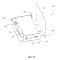
- FIG. 3 shows an example of embodiments of a charging device with retracted cables and an open cover.
- FIG. 4 shows an example of embodiments of a charging device with extended cables and a closed cover.
- FIG. 5 shows an example of embodiments of a charging device with retracted cables and a closed cover.
- FIG. 6 shows an example of embodiments of a charging device with extended cables and an open cover.
- FIG. 7 shows a side detail view for an example of embodiments of a charging device with retracted cables and a closed cover.
- FIG. 8 shows an example of embodiments of a charging device with retracted cables and a thermally conductive outer wall.
- FIG. 9 shows an expanded view of an example of embodiments of a charging device having a thermally conductive outer wall and a plurality of thermal interfaces coupled to electrical components inside the main body.
- FIG. 10 shows an expanded view of an example of embodiments of a charging device having a thermally conductive outer wall thermally coupled to a battery.
- FIG. 11 shows a schematic example of embodiments of a charging device with a first electrical cable configured to couple to a mobile electronic device, and with a second electrical cable configured to couple to a power source.
- a charging device 100 for charging an electronic device 150 a or 150 b can include a main body housing 128 with at least one recessed portion 120 , a battery 124 disposed inside the main body, and one or more electrical cables.
- the battery 124 can be a rechargeable battery (e.g., a lithium ion battery, a lithium polymer battery, or other suitable battery type).
- a charging device 100 can include a cover 102 and a thermally conductive outer wall 104 .
- the one or more electrical cables can each be movable between a retracted position and an extended position. In some embodiments, each of the cables can be disposed in the at least one recessed portion 120 when in the retracted position and extend outside the main body when in the extended position.
- FIGS. 1 , 3 , and 5 show examples of some embodiments of a charging device 100 with a retracted first electrical cable 106 and a retracted second electrical cable 110 .
- Charging device 100 can include a cover 102 .
- FIGS. 2 and 6 show examples of some embodiments of a charging device 100 with extended first and second electrical cables 106 and 110 , and an open cover 102 .
- the first electrical cable 106 and the second electrical cable 110 can be positioned in the recessed portion 120 .
- the first electrical cable 106 can be positioned on top of the second electrical cable 110 (e.g., as shown in FIG.
- the second electrical cable 110 can be positioned on top of the first electrical cable 106 .
- the retracted first and second electrical cables 106 and 110 can remain partially visible when the cover 102 is closed.
- the first and second electrical cables 106 and 110 can be configured so that once put in the extended position they will remain in the extended position without recoiling to the retracted position.
- the one or more electrical cables e.g., electrical cables 106 and 110
- a cover 102 for a charging device 100 can be movable relative to the main body housing 128 .
- the cover 102 can be movable between a closed position (as shown in FIG. 1 ) and an open position (as shown in FIG. 2 ).
- a cover 102 can at least partially cover a recessed portion 120 to impede the first and second electrical cables 106 and 110 from moving between the retracted positions and the extended positions.
- a cover 102 can be in the closed position to impede the first and second cables 106 and 110 from moving from the retract position into the extended position, as shown in FIGS. 1 and 5 .
- the cover 102 can be in the closed position to impede the first and second cables 106 and 110 from moving from the extended position into the retracted position, as shown in FIG. 4 .
- a hinge can connect the cover 102 to the main body housing 128 .
- Charging device 100 can in some embodiments include engaging mechanisms 130 configured to restrict the movement of a cover 102 away from the main body housing 128 .
- Engaging mechanisms 130 can in some embodiments include corresponding recessed portions and protrusions configured to snap together when engaged.
- engaging mechanisms 130 can include magnets configured to attract when in proximity in order to restrict the motion of the cover 102 .
- engaging mechanisms 130 can include a moveable pin configured to engage or disengage with a corresponding recess in response to user input.
- engaging mechanisms 130 can include a latch or hook or other retaining element.
- a charging device 100 can include first and second electrical cables 106 and 110 .
- a first electrical cable 106 can include a first electrical connector 108 configured to couple to a corresponding interface on an electronic device.
- the charging device 100 can be configured to charge the electronic device through the first electrical cable 106 using electrical power from a battery 124 disposed inside the main body 128 .
- a second electrical cable 110 can include a second electrical connector 112 configured to couple to a power source.
- the charging device can be configured to charge a battery 124 disposed inside the main body 128 using electrical power received from a power source 140 through the second electrical cable 110 .
- a charging device 100 can include three or more electrical cables (e.g., having two or more output electrical cables for charging multiple devices).
- a charging device 100 can have a single electrical cable configured to receive electrical power to charge the battery 124 in a recharge mode (e.g., when coupled to a power supply) and configured to output electrical power from the battery 124 when in a discharge mode (e.g., when doupled to a mobile electronic device).
- the charging device 100 can include the electrical cable 106 , which can be configured to output power from the battery 124 , and in some embodiments the electrical cable 110 can be omitted.
- the charging device 100 can include an electrical port configured to receive electrical power for recharging the battery 124 .
- the charging device 100 can include the electrical cable 110 , which can be configured to receive electrical power (e.g., from an external power supply) for charging the battery 124 , and in some embodiments the electrical cable 106 can be omitted.
- the charging device 100 can include an electrical port configured to output electrical power from the battery 124 .
- a charging device 100 can in some embodiments include a charge indicator 118 .
- a charging device 100 can include a battery indicator user input element 116 (e.g., a button).
- a charge indicator 118 can display the amount of charge remaining on a battery 124 disposed within the main housing 128 .
- the charge indictor 118 can, in some embodiments, include one or more lights (e.g., light emitting diodes (LEDs) configured such that the number of lights illuminated reflects the amount of charge remaining on a battery 124 (i.e. more lights illuminated indicates more charge remaining).
- a charge indicator 118 can in some embodiments be configured to indicate the amount of remaining charge at least in part by the color of light emitted.
- a charge indicator 118 can be configured to indicate the charge remaining on a battery 124 in response to user input received by the battery indicator user input element 116 (e.g., a user pressing the battery indicator button).
- a charging device can include an electrical port 114 .
- An electrical port 114 can be configured to receive an electrical connector and to output electrical power from a battery 124 disposed within main housing 128 .
- an electrical port 114 can be configured to interface with one or more of a variety of industry standard electrical cables.
- the electrical port 114 can be configured to interface with one or more of the following: a USB cable, a mini-USB cable, a FireWire interface (e.g., IEEE 1394 interface), a Thunderbolt interface, a wall or car charger, etc.
- a charging device 100 can be configure to supply electrical power or signals simultaneously to multiple devices.
- a charging device 100 can supply electrical power simultaneously through an electrical port 114 and a first electrical cable 106 (e.g., to simultaneously provide power to two electronic devices).
- the outer housing of the charging device 100 can be thermally conductive and can be thermally coupled to one or more electrical components (e.g., the battery 124 , a processor, etc.) that are inside the charging device 100 such that at least a portion of the outer housing of the charging device 100 can operate as a heat sink for the one or more electrical components.
- the charging device 100 can include a thermally conductive back portion (e.g., on a side opposite the cover 102 ), which can be a thermally conductive back plate 104 , as shown in FIGS. 8 through 10 , although other portions of the outer housing (e.g., one or more side edges and/or a front portion) can be thermally conductive and can be used as a heat sink similar to the disclosure provided herein for the back plate 104 .
- a thermally conductive back plate 104 can be made of a metal or a metal alloy. In some embodiments a thermally conductive back plate 104 can be made of aluminum. In some embodiments, a thermally conductive back plate 104 can be made of a plastic or ceramic material suitable for the effective transfer of heat. For example, the thermally conductive back plate 104 can have a thermal conductivity of at least about 10 W/mK, at least about 30 W/mK, at least about 50 W/mK, at least about 100 W/mK, at least about 150 W/mK, at least about 200 W/mK, or more, although other values can be used in some cases.
- the thermally conductive back plate 104 can have a thermal conductivity of less than or equal to about 2000 W/mK, less than or equal to about 1000 W/mK, less than or equal to about 5000 W/mK, less than or equal to about 300 W/mK, although other values can be used in some cases as defined by power load and efficiency, or thermal requirements.
- the thermally conductive back plate 104 can be configured to operate as a heat sink for a battery 124 disposed in a main body housing 128 .
- a thermally conductive back plate can be configured to operate as a heat sink for electrical components 126 disposed in a main body housing 128 .
- the electrical components 126 can in some embodiments include any number of electrical or electronic components not limited to one or more of the following: a processor, a switch, an inductor, a memory, a capacitor, a voltage monitor, a conductive connector, or a semi-conductive connector, a battery, or combinations thereof.
- the electrical components 126 can be on a printed circuit board or a flex circuit.
- a thermally conductive back plate 104 can be thermally coupled to one or more electrical components 126 .
- FIGS. 9 and 10 show expanded views of a charging device 100 with a thermally conductive back plate 104 displaced from its operable position in order to show the arrangement of electrical components 126 and thermal interfaces 122 .
- a thermally conductive back plate 104 can be coupled to one or more electrical components through one or more thermal interfaces 122 .
- a thermal interface 122 can include one or more of the following: thermal grease, thermal gel, thermal compound, thermal paste, heat paste, heat sink paste, heat sink compound, or a thermal pad, or a direct connection to the conductive back plate 104 can be used.
- more than one different thermal interface 122 can couple a thermally conductive back plate 104 to the electronic components 126 .
- a first thermal interface can couple the battery 124 to the thermally conductive back plate 104
- a second thermal interface can couple one or more other electrical components (e.g., a processor, etc.) to the thermally conductive back plate 104 .
- a single thermal interface can thermally couple multiple electrical components to the thermally conductive back plate 104 .
- one or more electrical components can be directly thermally coupled to the thermally conductive back plate 104 (e.g., using a single thermal interface between any of the electrical components and the thermally conductive back plate 104 ).
- the charging device 100 does not include a heat spreader between the one or more electrical components and the thermally conductive back plate 104 .
- a thermally conductive back plate 104 can be thermally coupled to a battery 124 . As shown in FIG. 10 , a thermally conductive back plate 104 can be coupled directly to a battery 124 . In some embodiments, a thermal interface 122 can thermally couple the thermally conductive back plate 104 with a battery 124 . In some embodiments, the same thermal interface 122 can couple the thermally conductive back plate 104 to a battery 124 and to other electrical components 126 . In some embodiments, a plurality of thermal interfaces 122 of one or more types can be used to couple the thermally conductive back plate 104 to electrical components 126 and a battery 124 . In some implementations, thermal paste can thermally couple the battery 124 to the thermally conductive back plate 104 , and a thermal pad can thermally couple the other electrical components 126 to the thermally conductive back plate 104 .
- a thermally conductive back plate 104 can be thermally coupled to a battery disposed entirely within a main housing 128 .
- a thermally conductive back plate 104 can be thermally coupled to other portions of the main housing 128 .
- one or more thermal interfaces 122 can thermally couple a thermally conductive back plate 104 with other portions of the main body housing 128 .
- FIG. 11 shows a schematic example of embodiments of a charging device 100 configured to interact with any combination of the following: a mobile electronic device 150 a by a first electrical cable 106 ; a mobile electronic device 150 b by electrical port 114 ; and a power source 140 by a second electrical cable 110 .
- the electrical port 114 can be omitted.
- a charging device 100 can be configured to interact with a power source 140 coupled to the charging device 100 (e.g., to charge the battery 124 in a charging mode), in some cases when no mobile electronic device 150 a or 150 b is coupled to the charging device 100 .
- the charging device 100 can be configured to interact with a mobile electronic device 150 a or 150 b that is coupled to the charging device 100 (e.g., to send power to the mobile electronic device 150 a or 150 b in a discharge mode), in some cases when no power source 140 is coupled to the charging device 100 .
- a charging device 100 can be configured to interact with both a power source 140 and one or more mobile electronic devices 150 a and/or 150 b simultaneity.
- the charging device 100 can pass electrical power received from the power source 140 to one or more mobile electronic devices 150 a and/or 150 b .
- electrical power can be passed from the power source 140 , through the charging device 100 , to the one or more mobile electronic devices 150 a and/or 150 b without going through the battery 124 (e.g., in a bypass mode).
- the mobile electronic device 150 a or 150 b can be a personal device configured to be portable and operate without a fixed connection to an external power source.
- the mobile electronic device 150 a or 150 b can be a cellular phone.
- An electronic device 150 a or 150 b can in some embodiments be an iPhone® or other smartphone.
- the electronic device 150 a or 150 b can in some embodiments be a laptop computer or a tablet computer.
- the mobile electronic device 150 a or 150 b can be a portable media player or recording device.
- a power source 140 can be any source of electrical power external to the charging device 100 .
- a power source can be a wall electrical outlet.
- a power source 140 can be an external battery.
- a power source 140 can be an external electronic device such as a computer (e.g., having a USB port capable of outputting electrical power).
- a charging device 100 can include electrical components 126 such a controller 132 and a memory 134 and additional electrical components, as discussed herein.
- the controller 132 can include one or more computer processors (e.g., a general purpose processor or a special purpose processor), which can be configured to execute computer-executable instructions stored on memory 134 to implement various features described herein.
- a controller 132 can determine when a charging device 100 has been connected to a mobile electronic device 150 a or 150 b , or to a power source 140 .
- a controller 132 can initiate an action in response to detecting the connection of a power source 140 or a mobile electronic device 150 a or 150 b to the charging device 100 , without further user input.
- Actions by the controller 132 can in some embodiments include initiating the charging of a battery 124 in response to detecting the connection to a power source 140 .
- Actions by controller 132 can in some embodiments include initiating the charging of a mobile electronic device 150 a or 150 b from a battery 124 in response to detecting the connection to a mobile electronic device 150 a or 150 b , and in some cases the controller 132 can detect the presence of charge on battery 124 , e.g., before outputting electrical power to charge a mobile electronic device 150 a or 150 b .
- a controller 132 can in some embodiments interact with one or more switches to direct electricity through in the charging device 100 .
- a controller 132 in some embodiments can interact with one or more voltage modifiers.
- a charging device 100 can be configured to pass charge directly from a power source 140 to an electronic device 150 a or 150 b .
- the charging device 100 can include a bypass electrical pathway from the second electrical cable 110 to the first electrical cable 106 , which can be used to relay electrical charge from the power source 140 , through the charging device 100 , to the electronic device 150 a or 150 b .
- the bypass electrical pathway can in some embodiments include or extend through a voltage modifier, which can adjust the voltage output by the charging device 100 to be a voltage acceptable to the mobile electronic device 150 a or 150 b .
- the bypass electrical pathway does not go through, or otherwise include, the battery 124 .
- a voltage modifier can adjust the voltage to an appropriate voltage level for the electronic device 150 a or 150 b .
- a discharge electrical pathway can be configured to deliver electrical power from the battery 124 to a mobile electronic device 150 a or 150 b via the electrical cable 106 or electrical port 114 .
- the discharge electrical pathway and the bypass electrical pathway can both use the same voltage modifier (e.g., the same boost converter or voltage regulator), although a bypass electrical pathway may use a different voltage modifier than the discharge electrical pathway in some implementations.
- a switch can be closed to direct electrical charge along the bypass electrical pathway (e.g., to charge the electronic device 150 a or 150 b using the power source 140 and bypassing the battery 124 ).
- the switch can be opened to disrupt the bypass electrical pathway (e.g., so that electrical power input through the second electrical cable 110 is not passed through to charge the electronic device 150 a or 150 b ).
- a portion of the electrical charge from a power source 140 can be used to charge the electronic device 150 a or 150 b
- a portion of the electrical charge is used to charge the battery 124 (e.g., via a charging electrical pathway from the electrical cable 110 to the battery 124 ).
- the charging device can be configured to direct electrical charge from power source 140 to both a battery 124 and to an electronic device 150 a or 150 b . Additional details are disclosed in U.S. Provisional Patent Application No. 62/045,461 (the '461 Application), titled “Systems and Methods for Battery Charging and Management,” and filed on Sep. 3, 2014, the entirety of which is hereby incorporated by reference.
- the charging device 100 can enable communication of data between an external electronic device (e.g., a personal computer, a laptop, a tablet computer, etc.) and one or more electronic devices 150 a and/or 150 b .
- the external electronic device can be a power source 140 , in some embodiments.
- One or more data communication lines can extend between the second electrical cable connector 112 and the first electrical cable connector 108 , and/or between the second electrical cable connector 112 and the electrical port 114 . Data can be passed through the charging device 100 (e.g., for syncing the electronic device 150 a or 150 b with an external electronic device such as a computer).
- the charging device 100 can receive information from the electronic device 150 a or 150 b (e.g., via the first electrical cable 106 or the electrical port 114 ).
- the charging device 100 can transfer the data to the second electrical cable connector 112 , where the data can be transmitted to an external electronic device.
- the second electrical cable connector 112 can receive data from an external electronic device (e.g., a personal computer, laptop, or tablet computer), and the charging device 100 can transmit the data to the first electrical cable connector 108 such that the data is communicated to the mobile electronic device 150 a or 150 b .
- the charging device 100 can enable the mobile electronic device 150 a or 150 b to send data to and/or receive data from an external electronic device that is coupled to the charging device 100 , and in many implementations without a direct data connection between the electronic device 150 a or 150 b and the external electronic device. Accordingly, a user can utilize the charging device 100 for syncing the electronic device 150 a or 150 b , so that the user does not need to carry a separate cable for syncing. In some embodiments, the charging device 100 can transmit electrical power from a power source 140 of an external electronic device to an electronic device 150 a or 150 b while simultaneously transmitting data between the external electronic device and the mobile electronic device 150 a or 150 b . Additional details disclosed in the '461 Application can be applied to the charging device 100 .
- Software can include computer-readable instructions stored in memory (e.g., non-transitory, tangible memory, such as solid state memory (e.g., ROM, EEPROM, FLASH, RAM), optical memory (e.g., a CD, DVD, Blu-ray disc, etc.), magnetic memory (e.g., a hard disc drive), etc.), configured to implement the algorithms on a general purpose computer, special purpose processors, or combinations thereof.
- memory e.g., non-transitory, tangible memory, such as solid state memory (e.g., ROM, EEPROM, FLASH, RAM), optical memory (e.g., a CD, DVD, Blu-ray disc, etc.), magnetic memory (e.g., a hard disc drive), etc.
- memory e.g., non-transitory, tangible memory, such as solid state memory (e.g., ROM, EEPROM, FLASH, RAM), optical memory (e.g., a CD, DVD, Blu-ray disc, etc.), magnetic memory (e
Abstract
Description
Claims (20)
Priority Applications (4)
| Application Number | Priority Date | Filing Date | Title |
|---|---|---|---|
| US14/536,505 US9153985B1 (en) | 2014-09-30 | 2014-11-07 | Portable charging device |
| DE202015002577.3U DE202015002577U1 (en) | 2014-09-30 | 2015-04-08 | Portable charging device |
| CN201520212163.6U CN204761047U (en) | 2014-09-30 | 2015-04-09 | Portable battery charging outfit |
| CN201510166849.0A CN106160044A (en) | 2014-09-30 | 2015-04-09 | Portable charging apparatus |
Applications Claiming Priority (2)
| Application Number | Priority Date | Filing Date | Title |
|---|---|---|---|
| US201462057591P | 2014-09-30 | 2014-09-30 | |
| US14/536,505 US9153985B1 (en) | 2014-09-30 | 2014-11-07 | Portable charging device |
Publications (1)
| Publication Number | Publication Date |
|---|---|
| US9153985B1 true US9153985B1 (en) | 2015-10-06 |
Family
ID=53185719
Family Applications (1)
| Application Number | Title | Priority Date | Filing Date |
|---|---|---|---|
| US14/536,505 Expired - Fee Related US9153985B1 (en) | 2014-09-30 | 2014-11-07 | Portable charging device |
Country Status (3)
| Country | Link |
|---|---|
| US (1) | US9153985B1 (en) |
| CN (2) | CN106160044A (en) |
| DE (1) | DE202015002577U1 (en) |
Cited By (47)
| Publication number | Priority date | Publication date | Assignee | Title |
|---|---|---|---|---|
| US20150146401A1 (en) * | 2013-11-22 | 2015-05-28 | AFC Trident, Inc. | Case for a portable electronic device having a cable to electrically couple the portable electronic device to an external device |
| US20150189780A1 (en) * | 2013-11-22 | 2015-07-02 | AFC Trident, Inc. | Case for a portable electronic device having an interface to provide for transmission of data bewteen the portable electronic device and an external device |
| US20160064963A1 (en) * | 2014-09-03 | 2016-03-03 | Mophie, Inc. | Systems and methods for battery charging and management |
| USD751056S1 (en) * | 2014-03-28 | 2016-03-08 | Hewlett-Packard Development Company, L.P. | Device |
| CN105811496A (en) * | 2016-03-03 | 2016-07-27 | 深圳市汇业电子有限公司 | Power smart lithium battery based on outdoor emergency operation and remote control |
| US9495375B2 (en) | 2013-11-27 | 2016-11-15 | Mophie, Inc. | Battery pack with supplemental memory |
| US9545542B2 (en) | 2011-03-25 | 2017-01-17 | May Patents Ltd. | System and method for a motion sensing device which provides a visual or audible indication |
| USD780725S1 (en) * | 2015-02-05 | 2017-03-07 | Lg Electronics Inc. | Adaptor for mobile phone |
| USD786790S1 (en) * | 2015-09-30 | 2017-05-16 | Halo International Sezc Ltd | Portable power charger |
| USD791070S1 (en) * | 2015-12-24 | 2017-07-04 | Samsung Electronics Co., Ltd. | Battery |
| US20170214268A1 (en) * | 2016-01-22 | 2017-07-27 | Boston Scientific Neuromodulation Corporation | Physically-Configurable External Charger for an Implantable Medical Device with Separable Coil and Electronics Housings |
| US9755444B2 (en) | 2013-02-25 | 2017-09-05 | Mophie, Inc. | Protective case with switch cover |
| USD797092S1 (en) | 2014-11-25 | 2017-09-12 | Mophie, Inc. | Case for a mobile electronic device |
| USD797044S1 (en) * | 2016-05-31 | 2017-09-12 | Halo International SEZC Ltd. | Portable power charger with AC and DC charging capability |
| USD797091S1 (en) | 2014-11-25 | 2017-09-12 | Mophie, Inc. | Case for a mobile electronic device |
| USD797093S1 (en) | 2014-12-03 | 2017-09-12 | Mophie, Inc. | Case for a mobile electronic device |
| USD797659S1 (en) * | 2015-01-05 | 2017-09-19 | Zound Industries International Ab | Power bank with data storage device |
| US9787808B1 (en) * | 2015-05-21 | 2017-10-10 | King David Gyasi | Combined cover and charging cord for a portable electronic device and associated use thereof |
| US9876522B2 (en) | 2013-03-15 | 2018-01-23 | Mophie, Inc. | Protective case for mobile device |
| USD812557S1 (en) | 2017-01-05 | 2018-03-13 | Advanced Wireless Innovations Llc | Portable power supply |
| USD814412S1 (en) * | 2016-11-10 | 2018-04-03 | Molonlave Group Llc | Portable battery charger |
| USD818431S1 (en) * | 2016-05-26 | 2018-05-22 | Thales Defense & Security, Inc. | Battery charger |
| USD828295S1 (en) * | 2017-04-24 | 2018-09-11 | Shenzhen Aukey E-Business Business Co., Ltd. | Portable charger |
| WO2018183104A1 (en) * | 2017-03-27 | 2018-10-04 | Lat Enterprises D/B/A Medipak Energy Systems | Portable power case |
| USD832785S1 (en) | 2017-01-05 | 2018-11-06 | Advanced Wireless Innovations, Llc | Portable power supply |
| US10170738B2 (en) | 2008-01-18 | 2019-01-01 | Mophie Inc. | Battery pack for mobile devices |
| US20190013686A1 (en) * | 2017-07-07 | 2019-01-10 | EcoFlow Technology Limited | Mobile power source |
| USD838240S1 (en) | 2017-01-05 | 2019-01-15 | Advanced Wireless Innovations, Llc | Portable power supply |
| USD838669S1 (en) | 2016-11-04 | 2019-01-22 | Halo International SEZC Ltd. | Portable power charger |
| USD839186S1 (en) | 2017-01-05 | 2019-01-29 | Advanced Wireless Innovations Llc | Portable power supply |
| US10305306B1 (en) | 2016-03-12 | 2019-05-28 | Krista Wardell | Jewelry phone charging systems |
| USD858530S1 (en) * | 2018-03-23 | 2019-09-03 | Gopod Group Ltd. | Multi-port docking station for mobile phone |
| USD861653S1 (en) | 2015-05-27 | 2019-10-01 | Mophie Inc. | Protective battery case for mobile communications device |
| US10516431B2 (en) | 2017-11-21 | 2019-12-24 | Mophie Inc. | Mobile device case for receiving wireless signals |
| US20200159299A1 (en) * | 2018-11-19 | 2020-05-21 | Cheng Uei Precision Industry Co., Ltd. | Power supply and electronic device including the same |
| US20200366109A1 (en) * | 2020-03-19 | 2020-11-19 | Ifory Limited | Portable power bank |
| WO2020262908A1 (en) * | 2019-06-24 | 2020-12-30 | Samsung Electronics Co., Ltd. | Input/output connector and electronic device including the same |
| USD911936S1 (en) | 2019-03-27 | 2021-03-02 | Halo International SEZC Ltd. | Portable power charger with air compressor hose |
| US11054863B1 (en) * | 2018-01-19 | 2021-07-06 | Hewlett-Packard Development Company, L.P. | Attachment of power cables to computing devices |
| WO2021150263A1 (en) * | 2020-01-24 | 2021-07-29 | Houriani Rodney | Data and power selectable device charger |
| US11190035B2 (en) * | 2018-12-21 | 2021-11-30 | Adeeb SOBH | Device for charging portable electronic devices |
| USD940647S1 (en) | 2019-01-07 | 2022-01-11 | Mophie Inc. | Battery pack |
| USD945961S1 (en) * | 2019-11-29 | 2022-03-15 | Dongguan Budi Electronic Co., Ltd | Wireless charger |
| USD950538S1 (en) * | 2016-03-03 | 2022-05-03 | Mophie Inc. | Case for a mobile electronic device |
| USD986165S1 (en) * | 2021-04-16 | 2023-05-16 | Jonathan Kinas | Battery charger |
| USD1008182S1 (en) * | 2023-08-01 | 2023-12-19 | Shenzhen Huanantong Electronic Technology Co., Ltd. | Charger |
| USD1013632S1 (en) * | 2023-08-01 | 2024-02-06 | Shenzhen Huanantong Electronic Technology Co., Ltd. | Charger |
Families Citing this family (1)
| Publication number | Priority date | Publication date | Assignee | Title |
|---|---|---|---|---|
| CN111512516A (en) * | 2018-09-28 | 2020-08-07 | 查奇塔布有限公司 | Portable charging device for portable electronic equipment |
Citations (188)
| Publication number | Priority date | Publication date | Assignee | Title |
|---|---|---|---|---|
| USD300831S (en) | 1986-04-28 | 1989-04-25 | Jenkins Henry C | Remote control |
| USD303799S (en) | 1986-06-12 | 1989-10-03 | Motorola, Inc. | Radio pager or similar article |
| US5001772A (en) | 1989-11-17 | 1991-03-19 | Jack N. Holcomb | Power pack with concealed radio transmitter for portable cellular telephone |
| US5368159A (en) | 1991-06-14 | 1994-11-29 | Daniels S.R.L. | Protection case for remote controls |
| US5508123A (en) | 1995-03-06 | 1996-04-16 | Wey Henn Co., Ltd. | Power supplying device |
| USD372896S (en) | 1995-06-13 | 1996-08-20 | Motorola, Inc. | Battery housing |
| US5586002A (en) | 1992-06-24 | 1996-12-17 | John Notarianni | Protective case and interface housing containing computer devices and the like |
| US5604050A (en) | 1995-06-13 | 1997-02-18 | Motorola Inc. | Latching mechanism and method of latching thereby |
| US5610979A (en) | 1995-09-19 | 1997-03-11 | Yu; Wen-Chung | Mobile phone holder having security and charging function |
| US5648712A (en) | 1995-08-29 | 1997-07-15 | Asian Micro Sources, Inc. | Universally interchangeable and modular power supply with integrated battery charger |
| US5708707A (en) | 1995-01-20 | 1998-01-13 | Nokia Mobile Phones Limited | Telephone holder |
| US5711013A (en) | 1995-01-18 | 1998-01-20 | Cycomm Corporation | Conformant compact portable cellular phone case system and connector |
| USD392248S (en) | 1995-09-13 | 1998-03-17 | Nokia Mobile Phones Limited | Battery |
| USD392939S (en) | 1996-02-23 | 1998-03-31 | Nokia Mobile Phone Limited | Battery |
| US5786106A (en) | 1996-06-24 | 1998-07-28 | Armani; Shane | Battery pack with interchangeable tag-along supplemental feature cartridge particularly for cellular telephones |
| USD400495S (en) | 1997-12-23 | 1998-11-03 | Motorola, Inc. | Auxiliary battery encasement |
| US5864766A (en) | 1996-08-13 | 1999-01-26 | Chiang; Chih-Cheng | Cellular telephone battery with auto-answering and hand-free functions |
| US5973477A (en) | 1998-12-16 | 1999-10-26 | Creation Intelligence Technology Co., Ltd. | Multi-purpose battery mobile phones |
| US6043626A (en) | 1996-10-29 | 2000-03-28 | Ericsson Inc. | Auxiliary battery holder with multicharger functionality |
| USD427193S (en) | 1999-03-29 | 2000-06-27 | Smartdisk Personal Storage Systems Corporation | Peripheral hard drive device |
| US6171138B1 (en) | 2000-01-28 | 2001-01-09 | Motorola, Inc. | Electrical connector for removable components |
| USD436596S1 (en) | 1999-07-10 | 2001-01-23 | Teac Corporation | Magnetic disc memory |
| US6184654B1 (en) | 1998-07-28 | 2001-02-06 | Double-Time Battery Corporation | Wearable docking-holster system, with energy management, to support portable electronic devices |
| US6208115B1 (en) | 1997-06-16 | 2001-03-27 | Yehuda Binder | Battery substitute pack |
| US6317313B1 (en) | 1999-11-09 | 2001-11-13 | Interlogix, Inc. | Case and cover for an electronic device |
| US6324380B1 (en) | 1997-02-28 | 2001-11-27 | Kyocera Corporation | Dual-mode satellite/terrestrial mobile communication unit |
| US20010054148A1 (en) | 2000-02-18 | 2001-12-20 | Frank Hoornaert | Field programmable smart card terminal and token device |
| USD460411S1 (en) | 2000-08-28 | 2002-07-16 | Shu Jane Wang | Battery for a handsfree mobile phone |
| US20020147035A1 (en) | 2001-04-10 | 2002-10-10 | Den-Tsai Su | Multifunctional battery box of a mobile telephone |
| US6538413B1 (en) | 1995-09-07 | 2003-03-25 | Intermec Ip Corp. | Battery pack with capacity and pre-removal indicators |
| US6555990B1 (en) | 2002-03-29 | 2003-04-29 | Fu-I Yang | Mobile telephone battery charger with power indicator means |
| US20030096642A1 (en) | 2001-11-19 | 2003-05-22 | Jerry Bessa | Case for cellular phone |
| US6614722B2 (en) | 1999-10-04 | 2003-09-02 | Diver Entertainment Systems, Inc. | System for housing an audio system in an aquatic environment |
| US20030218445A1 (en) | 2002-05-21 | 2003-11-27 | Behar Brad M. | Portable electronic device carrier and charger |
| US20030228866A1 (en) | 2002-05-24 | 2003-12-11 | Farhad Pezeshki | Mobile terminal system |
| USD487458S1 (en) | 2002-11-22 | 2004-03-09 | Gregoire Alexandre Gentil | Portable electronic storage device |
| US20040097256A1 (en) | 2000-08-31 | 2004-05-20 | Clemens Kujawski | Protective cover |
| US20040104268A1 (en) | 2002-07-30 | 2004-06-03 | Bailey Kenneth Stephen | Plug in credit card reader module for wireless cellular phone verifications |
| USD496029S1 (en) | 2003-03-10 | 2004-09-14 | Plantronics, Inc. | Cradle for communications headset |
| USD503679S1 (en) | 2004-06-24 | 2005-04-05 | Apple Computer, Inc. | Power adapter |
| US20050090301A1 (en) | 2002-02-06 | 2005-04-28 | Thorsten Lange | Holder for an electronic device |
| US20050231159A1 (en) | 2004-04-14 | 2005-10-20 | Jones James A Sr | Portable electronic device charger and method |
| US20050247787A1 (en) | 2002-02-12 | 2005-11-10 | Clay Von Mueller | Magnetic stripe reader with power management control for attachment to a PDA device |
| US20050248312A1 (en) | 2004-05-05 | 2005-11-10 | Advanced Connectek Inc. | Portable power supply with computer port |
| USD513617S1 (en) | 2004-09-15 | 2006-01-17 | International Business Machines Corporation | Digital audio player |
| US6992461B2 (en) | 2003-10-29 | 2006-01-31 | Hui-Hu Liang | Automotive-use charger flashing light array |
| USD515500S1 (en) | 2004-03-16 | 2006-02-21 | Spin Master Ltd. | Charging unit |
| US20060058073A1 (en) | 2004-01-29 | 2006-03-16 | Duck-Young Kim | Portable cellular phone holder which has an electric charging ability |
| US20060063569A1 (en) | 2004-09-20 | 2006-03-23 | Qualcomm Incorporated | Portable device with versatile user interface |
| USD518477S1 (en) | 2005-06-06 | 2006-04-04 | He-And Technology Co., Ltd. | Bluetooth earphone with a connector |
| USD520502S1 (en) | 2005-03-12 | 2006-05-09 | Hon Hai Precision Ind. Co., Ltd. | Network device |
| US20060099999A1 (en) | 2002-08-17 | 2006-05-11 | Young-Tae Park | Connector for charging cellular phone |
| USD525616S1 (en) | 2004-12-23 | 2006-07-25 | Apple Computer, Inc. | Stand |
| USD529495S1 (en) | 2005-05-11 | 2006-10-03 | Staples, The Office Superstore, Llc | Computer peripheral housing |
| US7166987B2 (en) | 2003-10-10 | 2007-01-23 | R. F. Tech Co., Ltd | Portable charger for mobile phone |
| US20070152633A1 (en) | 2006-01-04 | 2007-07-05 | Samsung Electronics Co., Ltd. | Cradle for use with a portable electronic appliance and a portable electronic appliance set including the cradle |
| US20070167190A1 (en) | 2006-01-18 | 2007-07-19 | Research In Motion Limited | Component-based mobile device |
| USD547057S1 (en) | 2007-01-22 | 2007-07-24 | Griffin Technology, Inc. | Decorative case for an MP3 player device |
| USD547056S1 (en) | 2007-01-22 | 2007-07-24 | Griffin Technology, Inc. | Decorative case for an MP3 player device |
| USD551216S1 (en) | 2006-03-29 | 2007-09-18 | He-And Technology Co., Ltd. | Bluetooth earphone and adapter |
| US20070236180A1 (en) | 2006-04-11 | 2007-10-11 | Andrew Rodgers | Recharging device for use with portable electronic devices |
| USD556681S1 (en) | 2007-03-07 | 2007-12-04 | Jwin Electronics Corp. | Battery pack with case for multimedia phone |
| US20070297149A1 (en) | 2001-11-19 | 2007-12-27 | Otter Products, Llc | Modular accessory for protective case enclosing touch screen device |
| USD558972S1 (en) | 2005-11-22 | 2008-01-08 | Jwin Electronics Corp. | Protective portable electronic device holder with auxiliary battery and charger |
| USD558973S1 (en) | 2007-04-23 | 2008-01-08 | I-Tec Electronics, Inc. | Audio accessory and storage case for portable digital electronic device |
| US20080007214A1 (en) | 2006-07-10 | 2008-01-10 | Lucent Trans Electronic Co., Ltd. | Carrying case with an emergency charger |
| USD560231S1 (en) | 2006-10-13 | 2008-01-22 | Cowon Systems, Inc. | Portable multimedia player |
| USD561092S1 (en) | 2007-03-07 | 2008-02-05 | Jwin Electronics Corp. | Combined battery pack and silicone case for multimedia phone |
| US7336973B2 (en) | 2002-10-30 | 2008-02-26 | Way Systems, Inc | Mobile communication device equipped with a magnetic stripe reader |
| US20080053770A1 (en) | 2006-08-31 | 2008-03-06 | Timothy Tynyk | Travel case for a portable electronic device |
| USD565571S1 (en) | 2006-11-08 | 2008-04-01 | Imation Corp. | Hard drive docking station |
| US20080096620A1 (en) | 2006-10-20 | 2008-04-24 | Lee Min-Soo | Mobile terminal and case for mobile terminal |
| USD568312S1 (en) | 2006-11-29 | 2008-05-06 | Hon Hai Precision Industry Co., Ltd. | External hard disk box |
| US20080108395A1 (en) | 2006-11-06 | 2008-05-08 | Samsung Electronics Co., Ltd. | Portable sub-battery pack, portable communication terminal, and system for cradling portable communication terminal |
| USD569629S1 (en) | 2006-12-13 | 2008-05-27 | Shenzhen Futaihong Precision Industry Co., Ltd. | Digital photo frame |
| US20080123287A1 (en) | 2006-11-27 | 2008-05-29 | Addonit Limited | Casings for hand-held electronic devices |
| US20080132289A1 (en) | 2004-01-30 | 2008-06-05 | Nokia Corporation | Protective devices for a mobile terminal |
| USD570772S1 (en) | 2007-03-06 | 2008-06-10 | Acco Brands Usa Llc | Power adapter |
| USD572250S1 (en) | 2007-08-07 | 2008-07-01 | Quanta Computer Inc. | USB wireless dongle |
| USD573946S1 (en) | 2007-08-24 | 2008-07-29 | Microsoft Corporation | Adapter |
| USD575056S1 (en) | 2008-02-19 | 2008-08-19 | Incase Designs Corporation | Portable electronic device case |
| USD575729S1 (en) | 2007-06-18 | 2008-08-26 | Sanyo Electric Co., Ltd. | Battery charger |
| US7428427B2 (en) | 2005-11-02 | 2008-09-23 | Sony Ericsson Mobile Communications Ab | IMF cover for a portable electronic device |
| USD579902S1 (en) | 2007-11-22 | 2008-11-04 | Samsung Electronics Co., Ltd. | Mobile phone |
| USD581151S1 (en) | 2008-02-19 | 2008-11-25 | Incase Designs Corporation | Portable electronic device case |
| USD584738S1 (en) | 2007-04-12 | 2009-01-13 | Lg Electronics Inc. | MP3 player |
| US7479759B2 (en) | 2004-02-26 | 2009-01-20 | Research In Motion Limited | Electronic device including handheld electronic device with dual battery configuration, and associated method |
| US20090051319A1 (en) | 2007-08-21 | 2009-02-26 | Asustek Computer Inc. | Phone charging stand |
| USD588147S1 (en) | 2008-01-18 | 2009-03-10 | Photonic Data Security, Llc | Secure portable data transport and storage system |
| USD587896S1 (en) | 2008-02-19 | 2009-03-10 | Incase Designs Corporation | Portable electronic device case |
| US20090069050A1 (en) | 2007-09-12 | 2009-03-12 | Devicefidelity, Inc. | Updating mobile devices with additional elements |
| US20090073650A1 (en) * | 2007-09-19 | 2009-03-19 | Giga-Byte Communications & Giga-Byte Technology Co., Ltd. | Holster for mobile electronic apparatus |
| USD589021S1 (en) | 2008-01-25 | 2009-03-24 | Samsung Electronics Co., Ltd. | Mobile phone |
| US20090144456A1 (en) | 2007-11-30 | 2009-06-04 | Alexander David Gelf | Interface Device for Securely Extending Computer Functionality |
| US20090143104A1 (en) | 2007-09-21 | 2009-06-04 | Michael Loh | Wireless smart card and integrated personal area network, near field communication and contactless payment system |
| USD593940S1 (en) | 2007-06-18 | 2009-06-09 | Sanyo Electric Co., Ltd. | Battery |
| USD594833S1 (en) | 2007-08-30 | 2009-06-23 | Lg Electronics Inc. | Cellular phone |
| US20090186264A1 (en) | 2008-01-18 | 2009-07-23 | Daniel Huang | Battery pack, holster, and extendible processing and interface platform for mobile devices |
| USD598414S1 (en) | 2008-03-17 | 2009-08-18 | Lg Electronics Inc. | Cellular phone |
| USD598375S1 (en) | 2008-07-07 | 2009-08-18 | Sanyo Electric Co., Ltd. | Battery charger |
| USD601583S1 (en) | 2006-09-11 | 2009-10-06 | Apple Inc. | Media device |
| USD601955S1 (en) | 2008-12-31 | 2009-10-13 | Ekko (Hk) Ltd | Charger |
| USD601959S1 (en) | 2007-06-04 | 2009-10-13 | Samsung Electronics Co., Ltd. | Battery case for a battery of a mobile communication terminal |
| US7612997B1 (en) | 2008-11-17 | 2009-11-03 | Incase Designs Corp. | Portable electronic device case with battery |
| USD603334S1 (en) | 2007-10-18 | 2009-11-03 | Kyosho Corporation | Battery charger for radio control toys |
| US20100026589A1 (en) | 2007-07-31 | 2010-02-04 | Weiping Dou | Antenna Design for an Attached Accessory |
| USD610538S1 (en) | 2009-09-21 | 2010-02-23 | Wu William C W | Portable rechargeable battery pack with retractable contact |
| US20100064883A1 (en) | 2008-06-10 | 2010-03-18 | Deshko Gynes | Compact modular wireless control devices |
| US7713073B2 (en) * | 2008-01-25 | 2010-05-11 | Transpower Technology Co., Ltd. | Power adapter |
| US20100117597A1 (en) | 2008-06-20 | 2010-05-13 | Ke-Guan Wang | Charger |
| USD618237S1 (en) | 2009-05-12 | 2010-06-22 | Datastore Technology Corp. | External storage device case |
| US20100190046A1 (en) | 2007-09-14 | 2010-07-29 | Shih-Hui Chen | Power Bank Apparatus |
| US7778410B2 (en) | 2006-06-09 | 2010-08-17 | Lite-On Technology Corp. | Personal audio listening device |
| US7782610B2 (en) | 2008-11-17 | 2010-08-24 | Incase Designs Corp. | Portable electronic device case with battery |
| USD623399S1 (en) | 2010-02-12 | 2010-09-14 | Scosche Industries, Inc. | Keychain USB cable |
| USD624747S1 (en) | 2010-02-12 | 2010-10-05 | Scosche Industries, Inc. | Keychain USB cable |
| USD628153S1 (en) | 2010-07-16 | 2010-11-30 | T-Mobile Usa, Inc. | Micro USB charger |
| USD628572S1 (en) | 2010-02-02 | 2010-12-07 | Datastore Technology Corp. | External storage device case |
| USD628535S1 (en) | 2010-06-24 | 2010-12-07 | Cheng Uei Precision Industry Co., Ltd. | Portable charger |
| USD632648S1 (en) | 2010-07-07 | 2011-02-15 | Samya Technology Co., Ltd. | Portable lithium power bank, power detector and separate battery charger three in one |
| USD633493S1 (en) | 2010-04-19 | 2011-03-01 | Apple Inc. | Electronic device |
| USD633908S1 (en) | 2010-04-19 | 2011-03-08 | Apple Inc. | Electronic device |
| USD634704S1 (en) | 2010-10-05 | 2011-03-22 | EcoloBlue, Inc | Solar charger |
| USD635961S1 (en) | 2010-02-12 | 2011-04-12 | Novero Canada Inc. | Headset and docking station |
| USD637952S1 (en) | 2010-04-05 | 2011-05-17 | Santom Ltd | Portable phone holder and solar charger |
| USD637951S1 (en) | 2010-07-29 | 2011-05-17 | Nokia Corporation | Charging plate |
| USD639731S1 (en) | 2010-10-26 | 2011-06-14 | Freda Chu | External battery |
| USD642516S1 (en) | 2009-05-29 | 2011-08-02 | Sony Corporation | Rechargeable battery |
| USD643427S1 (en) | 2010-09-27 | 2011-08-16 | Toshiba America Information Systems | Hard disk drive case |
| US20110215767A1 (en) * | 2002-11-22 | 2011-09-08 | Johnson Todd W | Battery pack |
| USD645050S1 (en) | 2010-12-30 | 2011-09-13 | Igo, Inc. | Collapsible USB key fob device |
| USD645049S1 (en) | 2010-12-30 | 2011-09-13 | iGo, Inc | Collapsible USB connector |
| USD647908S1 (en) | 2010-12-24 | 2011-11-01 | Hon Hai Precision Industry Co., Ltd. | Docking station |
| USD648270S1 (en) | 2011-01-26 | 2011-11-08 | Cham Battery Technology Co., Ltd. | Spare battery for cell phone |
| USD649932S1 (en) | 2011-04-22 | 2011-12-06 | Dominic Symons | Electrical device charger |
| USD652379S1 (en) | 2011-04-22 | 2012-01-17 | Scosche Industries, Inc. | Portable electronic device recharger |
| USD653207S1 (en) | 2011-04-22 | 2012-01-31 | Scosche Industries, Inc. | Portable electronic device recharger |
| USD654852S1 (en) | 2007-06-26 | 2012-02-28 | Hansen Leroy C | Portable battery power supply |
| USD654854S1 (en) | 2011-07-14 | 2012-02-28 | Mathew Inskeep | Battery charger and maintainer |
| USD656096S1 (en) | 2011-03-01 | 2012-03-20 | Sanyo Electric Co., Ltd. | Adapter for charging |
| USD659094S1 (en) | 2011-08-19 | 2012-05-08 | Mophie, Inc. | Portable battery charger |
| USD661249S1 (en) | 2011-04-18 | 2012-06-05 | Research In Motion Limited | Multimedia converter |
| USD662050S1 (en) | 2011-10-28 | 2012-06-19 | Hon Hai Precision Industry Co., Ltd. | Portable power bank |
| USD662904S1 (en) | 2011-11-01 | 2012-07-03 | Hon Hai Precision Industry Co., Ltd. | Set-top box |
| USD663684S1 (en) | 2011-11-17 | 2012-07-17 | Samya Technology Co., Ltd. | Portable power charger |
| USD663685S1 (en) | 2011-11-17 | 2012-07-17 | Samya Technology Co., Ltd. | Portable power charger |
| USD664502S1 (en) | 2012-04-24 | 2012-07-31 | Mathew Inskeep | Jump starter |
| USD664501S1 (en) | 2012-03-06 | 2012-07-31 | Mathew Inskeep | Battery charger |
| USD665732S1 (en) | 2011-09-12 | 2012-08-21 | Sanyo Electric Co., Ltd. | Battery |
| USD666144S1 (en) | 2011-08-19 | 2012-08-28 | Mophie, Inc. | Universal battery pack |
| USD667788S1 (en) | 2011-09-28 | 2012-09-25 | Huabin Mai | Portable power supply |
| USD671096S1 (en) | 2011-07-26 | 2012-11-20 | Samsung Electronics Co., Ltd. | Bluetooth dongle |
| USD672309S1 (en) | 2011-11-16 | 2012-12-11 | Hon Hai Precision Industry Co., Ltd. | Portable power bank |
| USD674748S1 (en) | 2012-05-03 | 2013-01-22 | Fka Distributing Co. | Portable power supply for a mobile device |
| USD675156S1 (en) | 2011-11-17 | 2013-01-29 | Scosche Industries, Inc. | Portable electronic device recharger |
| USD676380S1 (en) | 2012-06-20 | 2013-02-19 | Shenzhen Win-Top Electronic Tech Co., Ltd. | Portable charger with lights |
| USD677223S1 (en) | 2012-04-23 | 2013-03-05 | Samsung Electronics Co., Ltd. | Repeater |
| USD678187S1 (en) | 2012-07-13 | 2013-03-19 | Chao Kuang Huang | Mobile power pack |
| USD680063S1 (en) | 2012-01-18 | 2013-04-16 | Sanyo Electric Co., Ltd. | Battery |
| USD682202S1 (en) | 2012-10-01 | 2013-05-14 | Advanced Charging Technologies, LLC | Housing for a charging device |
| USD682197S1 (en) | 2012-11-07 | 2013-05-14 | Globexpress Co. Limited, DBA HKGE US Inc | Battery pack |
| USD682196S1 (en) | 2012-11-07 | 2013-05-14 | Globexpress Co. Limited | Battery pack with illuminated power button |
| USD682777S1 (en) | 2012-08-29 | 2013-05-21 | Sumeet Kumar Gupta | Battery for electronic equipment |
| USD682781S1 (en) | 2012-04-18 | 2013-05-21 | Mitsumi Electric Co., Ltd | AC/DC converter |
| USD683310S1 (en) | 2012-07-20 | 2013-05-28 | Scosche Industries, Inc. | Home charger |
| USD684571S1 (en) | 2012-09-07 | 2013-06-18 | Apple Inc. | Electronic device |
| USD685732S1 (en) | 2012-10-12 | 2013-07-09 | Adam C Miller | Flat charging cable |
| USD686150S1 (en) | 2012-06-07 | 2013-07-16 | Samsung Sdi Co., Ltd. | Battery |
| USD686153S1 (en) | 2012-06-20 | 2013-07-16 | Dexin Ming Electronics (Shenzhen) Co., Ltd. | Battery |
| USD686152S1 (en) | 2012-06-07 | 2013-07-16 | Samsung Sdi Co., Ltd. | Battery |
| US20130193911A1 (en) * | 2011-08-10 | 2013-08-01 | Garold C. Miller | Motion-actuated portable charger |
| USD689847S1 (en) | 2012-01-09 | 2013-09-17 | Mophie, Inc. | Mobile phone wireless earpiece and earpiece battery charger |
| US8541985B1 (en) | 2012-11-27 | 2013-09-24 | Gigastone America Corp | Multifunctional portable power bank |
| US8547061B1 (en) | 2012-11-27 | 2013-10-01 | Gigastone America Corp | Wireless hotpoint device |
| USD692379S1 (en) | 2012-10-16 | 2013-10-29 | Lg Electronics Inc. | Portable adaptor |
| USD692825S1 (en) | 2013-01-04 | 2013-11-05 | First Act, Inc. | Charger |
| USD693297S1 (en) | 2013-03-18 | 2013-11-12 | Mathew Inskeep | Portable power pack |
| USD693798S1 (en) | 2012-12-27 | 2013-11-19 | D-Link Corporation | Router |
| USD694703S1 (en) | 2013-06-24 | 2013-12-03 | Kevin Faro | Battery in shape of block |
| USD695214S1 (en) | 2012-05-04 | 2013-12-10 | Ecosol Technologies Inc. | Portable battery charger |
| USD697865S1 (en) | 2011-04-26 | 2014-01-21 | Sanyo Electric Co., Ltd. | Battery |
| USD699177S1 (en) | 2013-02-28 | 2014-02-11 | TRA Company Ltd. | Battery pack |
| US20140042969A1 (en) | 2011-08-10 | 2014-02-13 | Garold C. Miller | Multi-source power adapter |
| US20140051292A1 (en) | 2012-08-17 | 2014-02-20 | Advanced Charging Technologies, LLC | Power device |
| USD704135S1 (en) | 2013-05-10 | 2014-05-06 | S P Technologies LLC | Electronic charging device |
| USD714215S1 (en) | 2012-01-09 | 2014-09-30 | Mophie, Inc. | Mobile battery charger |
| USD720687S1 (en) | 2012-05-24 | 2015-01-06 | Mophie, Inc. | Mobile battery charger |
| USD721328S1 (en) | 2013-03-15 | 2015-01-20 | Advanced Charging Technologies, LLC | Housing for a charging device |
-
2014
- 2014-11-07 US US14/536,505 patent/US9153985B1/en not_active Expired - Fee Related
-
2015
- 2015-04-08 DE DE202015002577.3U patent/DE202015002577U1/en active Active
- 2015-04-09 CN CN201510166849.0A patent/CN106160044A/en active Pending
- 2015-04-09 CN CN201520212163.6U patent/CN204761047U/en not_active Expired - Fee Related
Patent Citations (196)
| Publication number | Priority date | Publication date | Assignee | Title |
|---|---|---|---|---|
| USD300831S (en) | 1986-04-28 | 1989-04-25 | Jenkins Henry C | Remote control |
| USD303799S (en) | 1986-06-12 | 1989-10-03 | Motorola, Inc. | Radio pager or similar article |
| US5001772A (en) | 1989-11-17 | 1991-03-19 | Jack N. Holcomb | Power pack with concealed radio transmitter for portable cellular telephone |
| US5368159A (en) | 1991-06-14 | 1994-11-29 | Daniels S.R.L. | Protection case for remote controls |
| US5586002A (en) | 1992-06-24 | 1996-12-17 | John Notarianni | Protective case and interface housing containing computer devices and the like |
| US5711013A (en) | 1995-01-18 | 1998-01-20 | Cycomm Corporation | Conformant compact portable cellular phone case system and connector |
| US5708707A (en) | 1995-01-20 | 1998-01-13 | Nokia Mobile Phones Limited | Telephone holder |
| US5508123A (en) | 1995-03-06 | 1996-04-16 | Wey Henn Co., Ltd. | Power supplying device |
| USD372896S (en) | 1995-06-13 | 1996-08-20 | Motorola, Inc. | Battery housing |
| US5604050A (en) | 1995-06-13 | 1997-02-18 | Motorola Inc. | Latching mechanism and method of latching thereby |
| US5648712A (en) | 1995-08-29 | 1997-07-15 | Asian Micro Sources, Inc. | Universally interchangeable and modular power supply with integrated battery charger |
| US6538413B1 (en) | 1995-09-07 | 2003-03-25 | Intermec Ip Corp. | Battery pack with capacity and pre-removal indicators |
| USD392248S (en) | 1995-09-13 | 1998-03-17 | Nokia Mobile Phones Limited | Battery |
| US5610979A (en) | 1995-09-19 | 1997-03-11 | Yu; Wen-Chung | Mobile phone holder having security and charging function |
| USD392939S (en) | 1996-02-23 | 1998-03-31 | Nokia Mobile Phone Limited | Battery |
| US5786106A (en) | 1996-06-24 | 1998-07-28 | Armani; Shane | Battery pack with interchangeable tag-along supplemental feature cartridge particularly for cellular telephones |
| US5864766A (en) | 1996-08-13 | 1999-01-26 | Chiang; Chih-Cheng | Cellular telephone battery with auto-answering and hand-free functions |
| US6043626A (en) | 1996-10-29 | 2000-03-28 | Ericsson Inc. | Auxiliary battery holder with multicharger functionality |
| US6324380B1 (en) | 1997-02-28 | 2001-11-27 | Kyocera Corporation | Dual-mode satellite/terrestrial mobile communication unit |
| US6208115B1 (en) | 1997-06-16 | 2001-03-27 | Yehuda Binder | Battery substitute pack |
| USD400495S (en) | 1997-12-23 | 1998-11-03 | Motorola, Inc. | Auxiliary battery encasement |
| US6184654B1 (en) | 1998-07-28 | 2001-02-06 | Double-Time Battery Corporation | Wearable docking-holster system, with energy management, to support portable electronic devices |
| US5973477A (en) | 1998-12-16 | 1999-10-26 | Creation Intelligence Technology Co., Ltd. | Multi-purpose battery mobile phones |
| USD427193S (en) | 1999-03-29 | 2000-06-27 | Smartdisk Personal Storage Systems Corporation | Peripheral hard drive device |
| USD436596S1 (en) | 1999-07-10 | 2001-01-23 | Teac Corporation | Magnetic disc memory |
| US6614722B2 (en) | 1999-10-04 | 2003-09-02 | Diver Entertainment Systems, Inc. | System for housing an audio system in an aquatic environment |
| US6317313B1 (en) | 1999-11-09 | 2001-11-13 | Interlogix, Inc. | Case and cover for an electronic device |
| US6171138B1 (en) | 2000-01-28 | 2001-01-09 | Motorola, Inc. | Electrical connector for removable components |
| US20010054148A1 (en) | 2000-02-18 | 2001-12-20 | Frank Hoornaert | Field programmable smart card terminal and token device |
| USD460411S1 (en) | 2000-08-28 | 2002-07-16 | Shu Jane Wang | Battery for a handsfree mobile phone |
| US20040097256A1 (en) | 2000-08-31 | 2004-05-20 | Clemens Kujawski | Protective cover |
| US20020147035A1 (en) | 2001-04-10 | 2002-10-10 | Den-Tsai Su | Multifunctional battery box of a mobile telephone |
| US20070297149A1 (en) | 2001-11-19 | 2007-12-27 | Otter Products, Llc | Modular accessory for protective case enclosing touch screen device |
| US20030096642A1 (en) | 2001-11-19 | 2003-05-22 | Jerry Bessa | Case for cellular phone |
| US20050090301A1 (en) | 2002-02-06 | 2005-04-28 | Thorsten Lange | Holder for an electronic device |
| US20050247787A1 (en) | 2002-02-12 | 2005-11-10 | Clay Von Mueller | Magnetic stripe reader with power management control for attachment to a PDA device |
| US6555990B1 (en) | 2002-03-29 | 2003-04-29 | Fu-I Yang | Mobile telephone battery charger with power indicator means |
| US20030218445A1 (en) | 2002-05-21 | 2003-11-27 | Behar Brad M. | Portable electronic device carrier and charger |
| US20030228866A1 (en) | 2002-05-24 | 2003-12-11 | Farhad Pezeshki | Mobile terminal system |
| US20040104268A1 (en) | 2002-07-30 | 2004-06-03 | Bailey Kenneth Stephen | Plug in credit card reader module for wireless cellular phone verifications |
| US20060099999A1 (en) | 2002-08-17 | 2006-05-11 | Young-Tae Park | Connector for charging cellular phone |
| US7336973B2 (en) | 2002-10-30 | 2008-02-26 | Way Systems, Inc | Mobile communication device equipped with a magnetic stripe reader |
| USD487458S1 (en) | 2002-11-22 | 2004-03-09 | Gregoire Alexandre Gentil | Portable electronic storage device |
| US20110215767A1 (en) * | 2002-11-22 | 2011-09-08 | Johnson Todd W | Battery pack |
| USD496029S1 (en) | 2003-03-10 | 2004-09-14 | Plantronics, Inc. | Cradle for communications headset |
| US7166987B2 (en) | 2003-10-10 | 2007-01-23 | R. F. Tech Co., Ltd | Portable charger for mobile phone |
| US6992461B2 (en) | 2003-10-29 | 2006-01-31 | Hui-Hu Liang | Automotive-use charger flashing light array |
| US20060058073A1 (en) | 2004-01-29 | 2006-03-16 | Duck-Young Kim | Portable cellular phone holder which has an electric charging ability |
| US7400917B2 (en) | 2004-01-30 | 2008-07-15 | Nokia Corporation | Protective devices for a mobile terminal |
| US20080132289A1 (en) | 2004-01-30 | 2008-06-05 | Nokia Corporation | Protective devices for a mobile terminal |
| US7479759B2 (en) | 2004-02-26 | 2009-01-20 | Research In Motion Limited | Electronic device including handheld electronic device with dual battery configuration, and associated method |
| USD515500S1 (en) | 2004-03-16 | 2006-02-21 | Spin Master Ltd. | Charging unit |
| US20050231159A1 (en) | 2004-04-14 | 2005-10-20 | Jones James A Sr | Portable electronic device charger and method |
| US20050248312A1 (en) | 2004-05-05 | 2005-11-10 | Advanced Connectek Inc. | Portable power supply with computer port |
| USD503679S1 (en) | 2004-06-24 | 2005-04-05 | Apple Computer, Inc. | Power adapter |
| USD513617S1 (en) | 2004-09-15 | 2006-01-17 | International Business Machines Corporation | Digital audio player |
| US20060063569A1 (en) | 2004-09-20 | 2006-03-23 | Qualcomm Incorporated | Portable device with versatile user interface |
| USD525616S1 (en) | 2004-12-23 | 2006-07-25 | Apple Computer, Inc. | Stand |
| USD520502S1 (en) | 2005-03-12 | 2006-05-09 | Hon Hai Precision Ind. Co., Ltd. | Network device |
| USD529495S1 (en) | 2005-05-11 | 2006-10-03 | Staples, The Office Superstore, Llc | Computer peripheral housing |
| USD518477S1 (en) | 2005-06-06 | 2006-04-04 | He-And Technology Co., Ltd. | Bluetooth earphone with a connector |
| US7428427B2 (en) | 2005-11-02 | 2008-09-23 | Sony Ericsson Mobile Communications Ab | IMF cover for a portable electronic device |
| USD558972S1 (en) | 2005-11-22 | 2008-01-08 | Jwin Electronics Corp. | Protective portable electronic device holder with auxiliary battery and charger |
| US20070152633A1 (en) | 2006-01-04 | 2007-07-05 | Samsung Electronics Co., Ltd. | Cradle for use with a portable electronic appliance and a portable electronic appliance set including the cradle |
| US20070167190A1 (en) | 2006-01-18 | 2007-07-19 | Research In Motion Limited | Component-based mobile device |
| USD551216S1 (en) | 2006-03-29 | 2007-09-18 | He-And Technology Co., Ltd. | Bluetooth earphone and adapter |
| US20070236180A1 (en) | 2006-04-11 | 2007-10-11 | Andrew Rodgers | Recharging device for use with portable electronic devices |
| US7778410B2 (en) | 2006-06-09 | 2010-08-17 | Lite-On Technology Corp. | Personal audio listening device |
| US20080007214A1 (en) | 2006-07-10 | 2008-01-10 | Lucent Trans Electronic Co., Ltd. | Carrying case with an emergency charger |
| US20080053770A1 (en) | 2006-08-31 | 2008-03-06 | Timothy Tynyk | Travel case for a portable electronic device |
| USD601583S1 (en) | 2006-09-11 | 2009-10-06 | Apple Inc. | Media device |
| USD560231S1 (en) | 2006-10-13 | 2008-01-22 | Cowon Systems, Inc. | Portable multimedia player |
| US20080096620A1 (en) | 2006-10-20 | 2008-04-24 | Lee Min-Soo | Mobile terminal and case for mobile terminal |
| US20080108395A1 (en) | 2006-11-06 | 2008-05-08 | Samsung Electronics Co., Ltd. | Portable sub-battery pack, portable communication terminal, and system for cradling portable communication terminal |
| USD565571S1 (en) | 2006-11-08 | 2008-04-01 | Imation Corp. | Hard drive docking station |
| US20080123287A1 (en) | 2006-11-27 | 2008-05-29 | Addonit Limited | Casings for hand-held electronic devices |
| USD568312S1 (en) | 2006-11-29 | 2008-05-06 | Hon Hai Precision Industry Co., Ltd. | External hard disk box |
| USD569629S1 (en) | 2006-12-13 | 2008-05-27 | Shenzhen Futaihong Precision Industry Co., Ltd. | Digital photo frame |
| USD547057S1 (en) | 2007-01-22 | 2007-07-24 | Griffin Technology, Inc. | Decorative case for an MP3 player device |
| USD547056S1 (en) | 2007-01-22 | 2007-07-24 | Griffin Technology, Inc. | Decorative case for an MP3 player device |
| USD570772S1 (en) | 2007-03-06 | 2008-06-10 | Acco Brands Usa Llc | Power adapter |
| USD561092S1 (en) | 2007-03-07 | 2008-02-05 | Jwin Electronics Corp. | Combined battery pack and silicone case for multimedia phone |
| USD556681S1 (en) | 2007-03-07 | 2007-12-04 | Jwin Electronics Corp. | Battery pack with case for multimedia phone |
| USD584738S1 (en) | 2007-04-12 | 2009-01-13 | Lg Electronics Inc. | MP3 player |
| USD558973S1 (en) | 2007-04-23 | 2008-01-08 | I-Tec Electronics, Inc. | Audio accessory and storage case for portable digital electronic device |
| USD601959S1 (en) | 2007-06-04 | 2009-10-13 | Samsung Electronics Co., Ltd. | Battery case for a battery of a mobile communication terminal |
| USD575729S1 (en) | 2007-06-18 | 2008-08-26 | Sanyo Electric Co., Ltd. | Battery charger |
| USD593940S1 (en) | 2007-06-18 | 2009-06-09 | Sanyo Electric Co., Ltd. | Battery |
| USD654852S1 (en) | 2007-06-26 | 2012-02-28 | Hansen Leroy C | Portable battery power supply |
| US20100026589A1 (en) | 2007-07-31 | 2010-02-04 | Weiping Dou | Antenna Design for an Attached Accessory |
| USD572250S1 (en) | 2007-08-07 | 2008-07-01 | Quanta Computer Inc. | USB wireless dongle |
| US20090051319A1 (en) | 2007-08-21 | 2009-02-26 | Asustek Computer Inc. | Phone charging stand |
| USD573946S1 (en) | 2007-08-24 | 2008-07-29 | Microsoft Corporation | Adapter |
| USD594833S1 (en) | 2007-08-30 | 2009-06-23 | Lg Electronics Inc. | Cellular phone |
| US20090069050A1 (en) | 2007-09-12 | 2009-03-12 | Devicefidelity, Inc. | Updating mobile devices with additional elements |
| US20100190046A1 (en) | 2007-09-14 | 2010-07-29 | Shih-Hui Chen | Power Bank Apparatus |
| US20090073650A1 (en) * | 2007-09-19 | 2009-03-19 | Giga-Byte Communications & Giga-Byte Technology Co., Ltd. | Holster for mobile electronic apparatus |
| US20090143104A1 (en) | 2007-09-21 | 2009-06-04 | Michael Loh | Wireless smart card and integrated personal area network, near field communication and contactless payment system |
| USD603334S1 (en) | 2007-10-18 | 2009-11-03 | Kyosho Corporation | Battery charger for radio control toys |
| USD579902S1 (en) | 2007-11-22 | 2008-11-04 | Samsung Electronics Co., Ltd. | Mobile phone |
| US20090144456A1 (en) | 2007-11-30 | 2009-06-04 | Alexander David Gelf | Interface Device for Securely Extending Computer Functionality |
| US20090186264A1 (en) | 2008-01-18 | 2009-07-23 | Daniel Huang | Battery pack, holster, and extendible processing and interface platform for mobile devices |
| USD588147S1 (en) | 2008-01-18 | 2009-03-10 | Photonic Data Security, Llc | Secure portable data transport and storage system |
| US7713073B2 (en) * | 2008-01-25 | 2010-05-11 | Transpower Technology Co., Ltd. | Power adapter |
| USD589021S1 (en) | 2008-01-25 | 2009-03-24 | Samsung Electronics Co., Ltd. | Mobile phone |
| USD587896S1 (en) | 2008-02-19 | 2009-03-10 | Incase Designs Corporation | Portable electronic device case |
| USD575056S1 (en) | 2008-02-19 | 2008-08-19 | Incase Designs Corporation | Portable electronic device case |
| USD582149S1 (en) | 2008-02-19 | 2008-12-09 | Incase Designs Corporation | Portable electronic device case |
| USD581151S1 (en) | 2008-02-19 | 2008-11-25 | Incase Designs Corporation | Portable electronic device case |
| USD598414S1 (en) | 2008-03-17 | 2009-08-18 | Lg Electronics Inc. | Cellular phone |
| US20100064883A1 (en) | 2008-06-10 | 2010-03-18 | Deshko Gynes | Compact modular wireless control devices |
| US20100117597A1 (en) | 2008-06-20 | 2010-05-13 | Ke-Guan Wang | Charger |
| USD598375S1 (en) | 2008-07-07 | 2009-08-18 | Sanyo Electric Co., Ltd. | Battery charger |
| US7782610B2 (en) | 2008-11-17 | 2010-08-24 | Incase Designs Corp. | Portable electronic device case with battery |
| US7612997B1 (en) | 2008-11-17 | 2009-11-03 | Incase Designs Corp. | Portable electronic device case with battery |
| USD601955S1 (en) | 2008-12-31 | 2009-10-13 | Ekko (Hk) Ltd | Charger |
| USD618237S1 (en) | 2009-05-12 | 2010-06-22 | Datastore Technology Corp. | External storage device case |
| USD642516S1 (en) | 2009-05-29 | 2011-08-02 | Sony Corporation | Rechargeable battery |
| USD610538S1 (en) | 2009-09-21 | 2010-02-23 | Wu William C W | Portable rechargeable battery pack with retractable contact |
| USD628572S1 (en) | 2010-02-02 | 2010-12-07 | Datastore Technology Corp. | External storage device case |
| USD635961S1 (en) | 2010-02-12 | 2011-04-12 | Novero Canada Inc. | Headset and docking station |
| USD623399S1 (en) | 2010-02-12 | 2010-09-14 | Scosche Industries, Inc. | Keychain USB cable |
| USD624747S1 (en) | 2010-02-12 | 2010-10-05 | Scosche Industries, Inc. | Keychain USB cable |
| USD637952S1 (en) | 2010-04-05 | 2011-05-17 | Santom Ltd | Portable phone holder and solar charger |
| USD636392S1 (en) | 2010-04-07 | 2011-04-19 | Apple Inc. | Electronic device with graphical user interface |
| USD633908S1 (en) | 2010-04-19 | 2011-03-08 | Apple Inc. | Electronic device |
| USD677657S1 (en) | 2010-04-19 | 2013-03-12 | Apple Inc. | Electronic device |
| USD671937S1 (en) | 2010-04-19 | 2012-12-04 | Apple Inc. | Electronic device |
| USD690693S1 (en) | 2010-04-19 | 2013-10-01 | Apple Inc. | Electronic device |
| USD688660S1 (en) | 2010-04-19 | 2013-08-27 | Apple Inc. | Electronic device with graphical user interface |
| USD633493S1 (en) | 2010-04-19 | 2011-03-01 | Apple Inc. | Electronic device |
| USD672343S1 (en) | 2010-04-19 | 2012-12-11 | Apple Inc. | Electronic device |
| USD628535S1 (en) | 2010-06-24 | 2010-12-07 | Cheng Uei Precision Industry Co., Ltd. | Portable charger |
| USD632648S1 (en) | 2010-07-07 | 2011-02-15 | Samya Technology Co., Ltd. | Portable lithium power bank, power detector and separate battery charger three in one |
| USD628153S1 (en) | 2010-07-16 | 2010-11-30 | T-Mobile Usa, Inc. | Micro USB charger |
| USD637951S1 (en) | 2010-07-29 | 2011-05-17 | Nokia Corporation | Charging plate |
| USD643427S1 (en) | 2010-09-27 | 2011-08-16 | Toshiba America Information Systems | Hard disk drive case |
| USD634704S1 (en) | 2010-10-05 | 2011-03-22 | EcoloBlue, Inc | Solar charger |
| USD639731S1 (en) | 2010-10-26 | 2011-06-14 | Freda Chu | External battery |
| USD647908S1 (en) | 2010-12-24 | 2011-11-01 | Hon Hai Precision Industry Co., Ltd. | Docking station |
| USD645050S1 (en) | 2010-12-30 | 2011-09-13 | Igo, Inc. | Collapsible USB key fob device |
| USD645049S1 (en) | 2010-12-30 | 2011-09-13 | iGo, Inc | Collapsible USB connector |
| USD648270S1 (en) | 2011-01-26 | 2011-11-08 | Cham Battery Technology Co., Ltd. | Spare battery for cell phone |
| USD656096S1 (en) | 2011-03-01 | 2012-03-20 | Sanyo Electric Co., Ltd. | Adapter for charging |
| USD661249S1 (en) | 2011-04-18 | 2012-06-05 | Research In Motion Limited | Multimedia converter |
| USD653207S1 (en) | 2011-04-22 | 2012-01-31 | Scosche Industries, Inc. | Portable electronic device recharger |
| USD652379S1 (en) | 2011-04-22 | 2012-01-17 | Scosche Industries, Inc. | Portable electronic device recharger |
| USD649932S1 (en) | 2011-04-22 | 2011-12-06 | Dominic Symons | Electrical device charger |
| USD697865S1 (en) | 2011-04-26 | 2014-01-21 | Sanyo Electric Co., Ltd. | Battery |
| USD654854S1 (en) | 2011-07-14 | 2012-02-28 | Mathew Inskeep | Battery charger and maintainer |
| USD671096S1 (en) | 2011-07-26 | 2012-11-20 | Samsung Electronics Co., Ltd. | Bluetooth dongle |
| US20140042969A1 (en) | 2011-08-10 | 2014-02-13 | Garold C. Miller | Multi-source power adapter |
| US20130193911A1 (en) * | 2011-08-10 | 2013-08-01 | Garold C. Miller | Motion-actuated portable charger |
| USD659094S1 (en) | 2011-08-19 | 2012-05-08 | Mophie, Inc. | Portable battery charger |
| USD666144S1 (en) | 2011-08-19 | 2012-08-28 | Mophie, Inc. | Universal battery pack |
| USD665732S1 (en) | 2011-09-12 | 2012-08-21 | Sanyo Electric Co., Ltd. | Battery |
| USD667788S1 (en) | 2011-09-28 | 2012-09-25 | Huabin Mai | Portable power supply |
| USD662050S1 (en) | 2011-10-28 | 2012-06-19 | Hon Hai Precision Industry Co., Ltd. | Portable power bank |
| USD662904S1 (en) | 2011-11-01 | 2012-07-03 | Hon Hai Precision Industry Co., Ltd. | Set-top box |
| USD672309S1 (en) | 2011-11-16 | 2012-12-11 | Hon Hai Precision Industry Co., Ltd. | Portable power bank |
| USD675156S1 (en) | 2011-11-17 | 2013-01-29 | Scosche Industries, Inc. | Portable electronic device recharger |
| USD663685S1 (en) | 2011-11-17 | 2012-07-17 | Samya Technology Co., Ltd. | Portable power charger |
| USD663684S1 (en) | 2011-11-17 | 2012-07-17 | Samya Technology Co., Ltd. | Portable power charger |
| USD689847S1 (en) | 2012-01-09 | 2013-09-17 | Mophie, Inc. | Mobile phone wireless earpiece and earpiece battery charger |
| USD714215S1 (en) | 2012-01-09 | 2014-09-30 | Mophie, Inc. | Mobile battery charger |
| USD680063S1 (en) | 2012-01-18 | 2013-04-16 | Sanyo Electric Co., Ltd. | Battery |
| USD664501S1 (en) | 2012-03-06 | 2012-07-31 | Mathew Inskeep | Battery charger |
| USD682781S1 (en) | 2012-04-18 | 2013-05-21 | Mitsumi Electric Co., Ltd | AC/DC converter |
| USD677223S1 (en) | 2012-04-23 | 2013-03-05 | Samsung Electronics Co., Ltd. | Repeater |
| USD664502S1 (en) | 2012-04-24 | 2012-07-31 | Mathew Inskeep | Jump starter |
| USD674748S1 (en) | 2012-05-03 | 2013-01-22 | Fka Distributing Co. | Portable power supply for a mobile device |
| USD695214S1 (en) | 2012-05-04 | 2013-12-10 | Ecosol Technologies Inc. | Portable battery charger |
| USD720687S1 (en) | 2012-05-24 | 2015-01-06 | Mophie, Inc. | Mobile battery charger |
| USD686152S1 (en) | 2012-06-07 | 2013-07-16 | Samsung Sdi Co., Ltd. | Battery |
| USD686150S1 (en) | 2012-06-07 | 2013-07-16 | Samsung Sdi Co., Ltd. | Battery |
| USD686153S1 (en) | 2012-06-20 | 2013-07-16 | Dexin Ming Electronics (Shenzhen) Co., Ltd. | Battery |
| USD676380S1 (en) | 2012-06-20 | 2013-02-19 | Shenzhen Win-Top Electronic Tech Co., Ltd. | Portable charger with lights |
| USD678187S1 (en) | 2012-07-13 | 2013-03-19 | Chao Kuang Huang | Mobile power pack |
| USD683310S1 (en) | 2012-07-20 | 2013-05-28 | Scosche Industries, Inc. | Home charger |
| US20140051292A1 (en) | 2012-08-17 | 2014-02-20 | Advanced Charging Technologies, LLC | Power device |
| USD682777S1 (en) | 2012-08-29 | 2013-05-21 | Sumeet Kumar Gupta | Battery for electronic equipment |
| USD684571S1 (en) | 2012-09-07 | 2013-06-18 | Apple Inc. | Electronic device |
| USD682202S1 (en) | 2012-10-01 | 2013-05-14 | Advanced Charging Technologies, LLC | Housing for a charging device |
| USD685732S1 (en) | 2012-10-12 | 2013-07-09 | Adam C Miller | Flat charging cable |
| USD692379S1 (en) | 2012-10-16 | 2013-10-29 | Lg Electronics Inc. | Portable adaptor |
| USD682196S1 (en) | 2012-11-07 | 2013-05-14 | Globexpress Co. Limited | Battery pack with illuminated power button |
| USD682197S1 (en) | 2012-11-07 | 2013-05-14 | Globexpress Co. Limited, DBA HKGE US Inc | Battery pack |
| US8547061B1 (en) | 2012-11-27 | 2013-10-01 | Gigastone America Corp | Wireless hotpoint device |
| US8541985B1 (en) | 2012-11-27 | 2013-09-24 | Gigastone America Corp | Multifunctional portable power bank |
| USD693798S1 (en) | 2012-12-27 | 2013-11-19 | D-Link Corporation | Router |
| USD692825S1 (en) | 2013-01-04 | 2013-11-05 | First Act, Inc. | Charger |
| USD699177S1 (en) | 2013-02-28 | 2014-02-11 | TRA Company Ltd. | Battery pack |
| USD721328S1 (en) | 2013-03-15 | 2015-01-20 | Advanced Charging Technologies, LLC | Housing for a charging device |
| USD693297S1 (en) | 2013-03-18 | 2013-11-12 | Mathew Inskeep | Portable power pack |
| USD704135S1 (en) | 2013-05-10 | 2014-05-06 | S P Technologies LLC | Electronic charging device |
| USD694703S1 (en) | 2013-06-24 | 2013-12-03 | Kevin Faro | Battery in shape of block |
Non-Patent Citations (14)
| Title |
|---|
| "Cheap DIY iPhone External Battery," dated Jul. 22, 2008, http://fastdad.wordpress.com/2008/07/22/cheap-diy-iphone-external-battery/. |
| Dave Rees, "Richard Solo Backup Battery for iPhone / iPod Review," dated Jun. 16, 2008, http://the-gadgeteer.com/2008/06/16/richard-solo-backup-battery-for-iphone-ipod/. |
| Devin Coldewey, "Combination iPhone battery pack and flash from FastMac," dated Nov. 4, 2008, http://crunchgear.com/2008/11/04/combination-iphone-battery-pack-and-flash-from-fastmac/. |
| Jeremy Horwitz, "iLuv i603 / i604 Rechargeable Lithium Polymer Batteries with Silicone Skin," dated Jun. 27, 2006, http://www.ilounge.com/index.php/reviews/entry/iluv-i603-rechargeable-lithium-polymer-battery-with-silicone-skin/. |
| Jeremy Horwitz, "Kensington Mini Battery Pack and Charger for iPhone and iPod," dated May 16, 2008, http://www.ilounge.com/index.php/reviews/entry/kensington-mini-battery-pack-and-charger-for-iphone-and-ipod/. |
| Kensington Mini Battery Pack and Charger for iPhone and iPod, dated Sep. 30, 2008, 1 page. |
| Sven Rafferty, "Mybat External Battery for iPhone and iPod," dated May 18, 2008, http://svenontech.com/reviews/?p=74. |
| U.S. Appl. No. 29/410,518 including its prosecution history, filed Jan. 9, 2012, To. |
| U.S. Appl. No. 29/422,897 including its prosecution history, filed May 24, 2012, Hasbrook. |
| U.S. Appl. No. 29/464,271 including its prosecution history, filed Aug. 14, 2013, To. |
| U.S. Appl. No. 29/475,951 including its prosecution history, filed Dec. 9, 2013, Hasbrook et al. |
| U.S. Appl. No. 29/478,243 including its prosecution history, filed Jan. 2, 2014, Kim. |
| U.S. Appl. No. 29/478,253 including its prosecution history, filed Jan. 2, 2014., Namminga. |
| U.S. Appl. No. 29/501,885 including its prosecution history, filed Sep. 9, 2014, mophie, Inc. |
Cited By (81)
| Publication number | Priority date | Publication date | Assignee | Title |
|---|---|---|---|---|
| US10559788B2 (en) | 2008-01-18 | 2020-02-11 | Mophie Inc. | Battery pack for mobile devices |
| US10170738B2 (en) | 2008-01-18 | 2019-01-01 | Mophie Inc. | Battery pack for mobile devices |
| US11141629B2 (en) | 2011-03-25 | 2021-10-12 | May Patents Ltd. | Device for displaying in response to a sensed motion |
| US10926140B2 (en) | 2011-03-25 | 2021-02-23 | May Patents Ltd. | Device for displaying in response to a sensed motion |
| US9757624B2 (en) | 2011-03-25 | 2017-09-12 | May Patents Ltd. | Motion sensing device which provides a visual indication with a wireless signal |
| US11605977B2 (en) | 2011-03-25 | 2023-03-14 | May Patents Ltd. | Device for displaying in response to a sensed motion |
| US9545542B2 (en) | 2011-03-25 | 2017-01-17 | May Patents Ltd. | System and method for a motion sensing device which provides a visual or audible indication |
| US9555292B2 (en) | 2011-03-25 | 2017-01-31 | May Patents Ltd. | System and method for a motion sensing device which provides a visual or audible indication |
| US11298593B2 (en) | 2011-03-25 | 2022-04-12 | May Patents Ltd. | Device for displaying in response to a sensed motion |
| US9592428B2 (en) | 2011-03-25 | 2017-03-14 | May Patents Ltd. | System and method for a motion sensing device which provides a visual or audible indication |
| US9630062B2 (en) | 2011-03-25 | 2017-04-25 | May Patents Ltd. | System and method for a motion sensing device which provides a visual or audible indication |
| US11305160B2 (en) | 2011-03-25 | 2022-04-19 | May Patents Ltd. | Device for displaying in response to a sensed motion |
| US10953290B2 (en) | 2011-03-25 | 2021-03-23 | May Patents Ltd. | Device for displaying in response to a sensed motion |
| US10525312B2 (en) | 2011-03-25 | 2020-01-07 | May Patents Ltd. | Device for displaying in response to a sensed motion |
| US9878214B2 (en) | 2011-03-25 | 2018-01-30 | May Patents Ltd. | System and method for a motion sensing device which provides a visual or audible indication |
| US11192002B2 (en) | 2011-03-25 | 2021-12-07 | May Patents Ltd. | Device for displaying in response to a sensed motion |
| US11260273B2 (en) | 2011-03-25 | 2022-03-01 | May Patents Ltd. | Device for displaying in response to a sensed motion |
| US11631996B2 (en) | 2011-03-25 | 2023-04-18 | May Patents Ltd. | Device for displaying in response to a sensed motion |
| US11631994B2 (en) | 2011-03-25 | 2023-04-18 | May Patents Ltd. | Device for displaying in response to a sensed motion |
| US11173353B2 (en) | 2011-03-25 | 2021-11-16 | May Patents Ltd. | Device for displaying in response to a sensed motion |
| US11689055B2 (en) | 2011-03-25 | 2023-06-27 | May Patents Ltd. | System and method for a motion sensing device |
| US9764201B2 (en) | 2011-03-25 | 2017-09-19 | May Patents Ltd. | Motion sensing device with an accelerometer and a digital display |
| US9782637B2 (en) | 2011-03-25 | 2017-10-10 | May Patents Ltd. | Motion sensing device which provides a signal in response to the sensed motion |
| US11916401B2 (en) | 2011-03-25 | 2024-02-27 | May Patents Ltd. | Device for displaying in response to a sensed motion |
| US9808678B2 (en) | 2011-03-25 | 2017-11-07 | May Patents Ltd. | Device for displaying in respose to a sensed motion |
| US9868034B2 (en) | 2011-03-25 | 2018-01-16 | May Patents Ltd. | System and method for a motion sensing device which provides a visual or audible indication |
| US11949241B2 (en) | 2011-03-25 | 2024-04-02 | May Patents Ltd. | Device for displaying in response to a sensed motion |
| US9878228B2 (en) | 2011-03-25 | 2018-01-30 | May Patents Ltd. | System and method for a motion sensing device which provides a visual or audible indication |
| US9755444B2 (en) | 2013-02-25 | 2017-09-05 | Mophie, Inc. | Protective case with switch cover |
| US9876522B2 (en) | 2013-03-15 | 2018-01-23 | Mophie, Inc. | Protective case for mobile device |
| US20150189780A1 (en) * | 2013-11-22 | 2015-07-02 | AFC Trident, Inc. | Case for a portable electronic device having an interface to provide for transmission of data bewteen the portable electronic device and an external device |
| US20150146401A1 (en) * | 2013-11-22 | 2015-05-28 | AFC Trident, Inc. | Case for a portable electronic device having a cable to electrically couple the portable electronic device to an external device |
| US9495375B2 (en) | 2013-11-27 | 2016-11-15 | Mophie, Inc. | Battery pack with supplemental memory |
| USD751056S1 (en) * | 2014-03-28 | 2016-03-08 | Hewlett-Packard Development Company, L.P. | Device |
| US10079496B2 (en) | 2014-09-03 | 2018-09-18 | Mophie Inc. | Systems for managing charging devices based on battery health information |
| US10033204B2 (en) * | 2014-09-03 | 2018-07-24 | Mophie, Inc. | Systems and methods for battery charging and management |
| US9997933B2 (en) | 2014-09-03 | 2018-06-12 | Mophie, Inc. | Systems and methods for battery charging and management |
| US20160064963A1 (en) * | 2014-09-03 | 2016-03-03 | Mophie, Inc. | Systems and methods for battery charging and management |
| US11824383B2 (en) | 2014-09-09 | 2023-11-21 | Bollinger Industries, Inc. | Portable power charger with air compressor |
| USD797092S1 (en) | 2014-11-25 | 2017-09-12 | Mophie, Inc. | Case for a mobile electronic device |
| USD797091S1 (en) | 2014-11-25 | 2017-09-12 | Mophie, Inc. | Case for a mobile electronic device |
| USD797093S1 (en) | 2014-12-03 | 2017-09-12 | Mophie, Inc. | Case for a mobile electronic device |
| USD797659S1 (en) * | 2015-01-05 | 2017-09-19 | Zound Industries International Ab | Power bank with data storage device |
| USD780725S1 (en) * | 2015-02-05 | 2017-03-07 | Lg Electronics Inc. | Adaptor for mobile phone |
| US9787808B1 (en) * | 2015-05-21 | 2017-10-10 | King David Gyasi | Combined cover and charging cord for a portable electronic device and associated use thereof |
| USD861653S1 (en) | 2015-05-27 | 2019-10-01 | Mophie Inc. | Protective battery case for mobile communications device |
| USD786790S1 (en) * | 2015-09-30 | 2017-05-16 | Halo International Sezc Ltd | Portable power charger |
| USD791070S1 (en) * | 2015-12-24 | 2017-07-04 | Samsung Electronics Co., Ltd. | Battery |
| US20170214268A1 (en) * | 2016-01-22 | 2017-07-27 | Boston Scientific Neuromodulation Corporation | Physically-Configurable External Charger for an Implantable Medical Device with Separable Coil and Electronics Housings |
| CN105811496A (en) * | 2016-03-03 | 2016-07-27 | 深圳市汇业电子有限公司 | Power smart lithium battery based on outdoor emergency operation and remote control |
| USD950538S1 (en) * | 2016-03-03 | 2022-05-03 | Mophie Inc. | Case for a mobile electronic device |
| US10305306B1 (en) | 2016-03-12 | 2019-05-28 | Krista Wardell | Jewelry phone charging systems |
| USD909292S1 (en) | 2016-05-26 | 2021-02-02 | Thales Defense & Security, Inc. | Battery charger |
| USD818431S1 (en) * | 2016-05-26 | 2018-05-22 | Thales Defense & Security, Inc. | Battery charger |
| USD797044S1 (en) * | 2016-05-31 | 2017-09-12 | Halo International SEZC Ltd. | Portable power charger with AC and DC charging capability |
| USD838669S1 (en) | 2016-11-04 | 2019-01-22 | Halo International SEZC Ltd. | Portable power charger |
| USD814412S1 (en) * | 2016-11-10 | 2018-04-03 | Molonlave Group Llc | Portable battery charger |
| USD838240S1 (en) | 2017-01-05 | 2019-01-15 | Advanced Wireless Innovations, Llc | Portable power supply |
| USD839186S1 (en) | 2017-01-05 | 2019-01-29 | Advanced Wireless Innovations Llc | Portable power supply |
| USD812557S1 (en) | 2017-01-05 | 2018-03-13 | Advanced Wireless Innovations Llc | Portable power supply |
| USD832785S1 (en) | 2017-01-05 | 2018-11-06 | Advanced Wireless Innovations, Llc | Portable power supply |
| WO2018183104A1 (en) * | 2017-03-27 | 2018-10-04 | Lat Enterprises D/B/A Medipak Energy Systems | Portable power case |
| USD828295S1 (en) * | 2017-04-24 | 2018-09-11 | Shenzhen Aukey E-Business Business Co., Ltd. | Portable charger |
| US20190013686A1 (en) * | 2017-07-07 | 2019-01-10 | EcoFlow Technology Limited | Mobile power source |
| US10516431B2 (en) | 2017-11-21 | 2019-12-24 | Mophie Inc. | Mobile device case for receiving wireless signals |
| US11054863B1 (en) * | 2018-01-19 | 2021-07-06 | Hewlett-Packard Development Company, L.P. | Attachment of power cables to computing devices |
| USD858530S1 (en) * | 2018-03-23 | 2019-09-03 | Gopod Group Ltd. | Multi-port docking station for mobile phone |
| US20200159299A1 (en) * | 2018-11-19 | 2020-05-21 | Cheng Uei Precision Industry Co., Ltd. | Power supply and electronic device including the same |
| US11190035B2 (en) * | 2018-12-21 | 2021-11-30 | Adeeb SOBH | Device for charging portable electronic devices |
| USD940647S1 (en) | 2019-01-07 | 2022-01-11 | Mophie Inc. | Battery pack |
| USD956686S1 (en) | 2019-01-07 | 2022-07-05 | Mophie Inc. | Battery pack |
| USD911936S1 (en) | 2019-03-27 | 2021-03-02 | Halo International SEZC Ltd. | Portable power charger with air compressor hose |
| US11545778B2 (en) | 2019-06-24 | 2023-01-03 | Samsung Electronics Co., Ltd. | Input/output connector and electronic device including the same |
| WO2020262908A1 (en) * | 2019-06-24 | 2020-12-30 | Samsung Electronics Co., Ltd. | Input/output connector and electronic device including the same |
| US11146013B2 (en) | 2019-06-24 | 2021-10-12 | Samsung Electronics Co., Ltd. | Input/output connector and electronic device including the same |
| USD945961S1 (en) * | 2019-11-29 | 2022-03-15 | Dongguan Budi Electronic Co., Ltd | Wireless charger |
| WO2021150263A1 (en) * | 2020-01-24 | 2021-07-29 | Houriani Rodney | Data and power selectable device charger |
| US20200366109A1 (en) * | 2020-03-19 | 2020-11-19 | Ifory Limited | Portable power bank |
| USD986165S1 (en) * | 2021-04-16 | 2023-05-16 | Jonathan Kinas | Battery charger |
| USD1008182S1 (en) * | 2023-08-01 | 2023-12-19 | Shenzhen Huanantong Electronic Technology Co., Ltd. | Charger |
| USD1013632S1 (en) * | 2023-08-01 | 2024-02-06 | Shenzhen Huanantong Electronic Technology Co., Ltd. | Charger |
Also Published As
| Publication number | Publication date |
|---|---|
| DE202015002577U1 (en) | 2015-04-30 |
| CN106160044A (en) | 2016-11-23 |
| CN204761047U (en) | 2015-11-11 |
Similar Documents
| Publication | Publication Date | Title |
|---|---|---|
| US9153985B1 (en) | Portable charging device | |
| TWI566498B (en) | Mobile power capable of carrying charging adapter and supporting recognition of two-dimensional barcode | |
| US10250056B2 (en) | Multi-function external attachment and safety circuit for a portable power charger | |
| US11005279B2 (en) | Compact portable battery charger | |
| KR101819040B1 (en) | Detachable computing system having dual batteries | |
| US9722654B2 (en) | Smart ultra box and protective case with the same | |
| US20110163719A1 (en) | Universal Charger | |
| US20130082543A1 (en) | Portable power supply | |
| US20160211616A9 (en) | High Power Rechargeable Flashlight With Two Way Universal Serial BUS | |
| US20150288215A1 (en) | Charger device with network connectivity | |
| JP2013529365A (en) | Power module for portable devices | |
| TWM513505U (en) | Power bank and protective case thereof | |
| US20230097239A1 (en) | Wireless mobile battery | |
| US9647713B2 (en) | Smart ultra box, protective case and mobile phone protective case with the same | |
| US20200287396A1 (en) | Protective casing for portable terminal with built-in auxiliary battery | |
| JP3170782U (en) | Hidden structure of transmission cable for 3C electrical products | |
| TW201701563A (en) | Mobile charge-discharge device | |
| US20150162756A1 (en) | Back-up power supply for mobile phone | |
| TWI554000B (en) | Mobile charge-discharge device | |
| TW201601414A (en) | Mobile power bank | |
| US20160111828A1 (en) | Usb device | |
| KR20140067321A (en) | Data storage devices are equipped with a portable battery charging devices | |
| US8651687B1 (en) | Charging device for a light | |
| WO2017208224A1 (en) | A compact retractable connectors charger for mobile devices | |
| US20140185203A1 (en) | Electronic device with battery |
Legal Events
| Date | Code | Title | Description |
|---|---|---|---|
| AS | Assignment |
Owner name: MOPHIE, INC., CALIFORNIA Free format text: ASSIGNMENT OF ASSIGNORS INTEREST;ASSIGNORS:GJOVIK, ERIK JOHN;PARK, SOO YOUN;LEE, SAI KONG FRANK;SIGNING DATES FROM 20141211 TO 20150112;REEL/FRAME:034780/0192 |
|
| STCF | Information on status: patent grant |
Free format text: PATENTED CASE |
|
| AS | Assignment |
Owner name: KEYBANK NATIONAL ASSOCIATION, OHIO Free format text: INTELLECTUAL PROPERTY SECURITY AGREEMENT;ASSIGNOR:MOPHIE INC.;REEL/FRAME:038012/0900 Effective date: 20160303 |
|
| FEPP | Fee payment procedure |
Free format text: ENTITY STATUS SET TO UNDISCOUNTED (ORIGINAL EVENT CODE: BIG.); ENTITY STATUS OF PATENT OWNER: LARGE ENTITY |
|
| MAFP | Maintenance fee payment |
Free format text: PAYMENT OF MAINTENANCE FEE, 4TH YEAR, LARGE ENTITY (ORIGINAL EVENT CODE: M1551); ENTITY STATUS OF PATENT OWNER: LARGE ENTITY Year of fee payment: 4 |
|
| AS | Assignment |
Owner name: LYNX HOLDINGS V, LLC, TEXAS Free format text: SECURITY INTEREST;ASSIGNOR:MOPHIE, INC.;REEL/FRAME:055381/0484 Effective date: 20210222 |
|
| AS | Assignment |
Owner name: BLUE TORCH FINANCE, LLC, NEW YORK Free format text: SECURITY INTEREST;ASSIGNORS:ZAGG INC.;MOPHIE INC.;HALO2CLOUD, LLC;REEL/FRAME:056972/0857 Effective date: 20210723 |
|
| AS | Assignment |
Owner name: MOPHIE INC., UTAH Free format text: RELEASE BY SECURED PARTY;ASSIGNOR:LYNX HOLDINGS V, LLC;REEL/FRAME:057650/0190 Effective date: 20210723 |
|
| AS | Assignment |
Owner name: HALO2CLOUD, LLC, UTAH Free format text: RELEASE BY SECURED PARTY;ASSIGNOR:BLUE TORCH FINANCE, LLC;REEL/FRAME:061085/0585 Effective date: 20220804 Owner name: MOPHIE INC., UTAH Free format text: RELEASE BY SECURED PARTY;ASSIGNOR:BLUE TORCH FINANCE, LLC;REEL/FRAME:061085/0585 Effective date: 20220804 Owner name: ZAGG INC, UTAH Free format text: RELEASE BY SECURED PARTY;ASSIGNOR:BLUE TORCH FINANCE, LLC;REEL/FRAME:061085/0585 Effective date: 20220804 |
|
| FEPP | Fee payment procedure |
Free format text: MAINTENANCE FEE REMINDER MAILED (ORIGINAL EVENT CODE: REM.); ENTITY STATUS OF PATENT OWNER: LARGE ENTITY |
|
| LAPS | Lapse for failure to pay maintenance fees |
Free format text: PATENT EXPIRED FOR FAILURE TO PAY MAINTENANCE FEES (ORIGINAL EVENT CODE: EXP.); ENTITY STATUS OF PATENT OWNER: LARGE ENTITY |
|
| STCH | Information on status: patent discontinuation |
Free format text: PATENT EXPIRED DUE TO NONPAYMENT OF MAINTENANCE FEES UNDER 37 CFR 1.362 |
|
| FP | Lapsed due to failure to pay maintenance fee |
Effective date: 20231006 |