US9085084B2 - Robot manipulator system - Google Patents

Robot manipulator system Download PDF

Info

Publication number
US9085084B2
US9085084B2 US13/907,053 US201313907053A US9085084B2 US 9085084 B2 US9085084 B2 US 9085084B2 US 201313907053 A US201313907053 A US 201313907053A US 9085084 B2 US9085084 B2 US 9085084B2
Authority
US
United States
Prior art keywords
robot
manipulator
robot manipulator
heatable
temperature
Prior art date
Legal status (The legal status is an assumption and is not a legal conclusion. Google has not performed a legal analysis and makes no representation as to the accuracy of the status listed.)
Active, expires
Application number
US13/907,053
Other versions
US20130268117A1 (en
Inventor
Harald STAAB
Sönke Kock
Current Assignee (The listed assignees may be inaccurate. Google has not performed a legal analysis and makes no representation or warranty as to the accuracy of the list.)
ABB AG Germany
Original Assignee
ABB AG Germany
Priority date (The priority date is an assumption and is not a legal conclusion. Google has not performed a legal analysis and makes no representation as to the accuracy of the date listed.)
Filing date
Publication date
Application filed by ABB AG Germany filed Critical ABB AG Germany
Assigned to ABB AG reassignment ABB AG ASSIGNMENT OF ASSIGNORS INTEREST (SEE DOCUMENT FOR DETAILS). Assignors: STAAB, HARALD, KOCK, SONKE
Publication of US20130268117A1 publication Critical patent/US20130268117A1/en
Application granted granted Critical
Publication of US9085084B2 publication Critical patent/US9085084B2/en
Active legal-status Critical Current
Adjusted expiration legal-status Critical

Links

Images

Classifications

    • BPERFORMING OPERATIONS; TRANSPORTING
    • B25HAND TOOLS; PORTABLE POWER-DRIVEN TOOLS; MANIPULATORS
    • B25JMANIPULATORS; CHAMBERS PROVIDED WITH MANIPULATION DEVICES
    • B25J9/00Programme-controlled manipulators
    • B25J9/16Programme controls
    • B25J9/1694Programme controls characterised by use of sensors other than normal servo-feedback from position, speed or acceleration sensors, perception control, multi-sensor controlled systems, sensor fusion
    • BPERFORMING OPERATIONS; TRANSPORTING
    • B25HAND TOOLS; PORTABLE POWER-DRIVEN TOOLS; MANIPULATORS
    • B25JMANIPULATORS; CHAMBERS PROVIDED WITH MANIPULATION DEVICES
    • B25J13/00Controls for manipulators
    • B25J13/08Controls for manipulators by means of sensing devices, e.g. viewing or touching devices
    • B25J13/087Controls for manipulators by means of sensing devices, e.g. viewing or touching devices for sensing other physical parameters, e.g. electrical or chemical properties
    • BPERFORMING OPERATIONS; TRANSPORTING
    • B25HAND TOOLS; PORTABLE POWER-DRIVEN TOOLS; MANIPULATORS
    • B25JMANIPULATORS; CHAMBERS PROVIDED WITH MANIPULATION DEVICES
    • B25J19/00Accessories fitted to manipulators, e.g. for monitoring, for viewing; Safety devices combined with or specially adapted for use in connection with manipulators
    • YGENERAL TAGGING OF NEW TECHNOLOGICAL DEVELOPMENTS; GENERAL TAGGING OF CROSS-SECTIONAL TECHNOLOGIES SPANNING OVER SEVERAL SECTIONS OF THE IPC; TECHNICAL SUBJECTS COVERED BY FORMER USPC CROSS-REFERENCE ART COLLECTIONS [XRACs] AND DIGESTS
    • Y10TECHNICAL SUBJECTS COVERED BY FORMER USPC
    • Y10STECHNICAL SUBJECTS COVERED BY FORMER USPC CROSS-REFERENCE ART COLLECTIONS [XRACs] AND DIGESTS
    • Y10S901/00Robots
    • Y10S901/02Arm motion controller
    • Y10S901/09Closed loop, sensor feedback controls arm movement
    • YGENERAL TAGGING OF NEW TECHNOLOGICAL DEVELOPMENTS; GENERAL TAGGING OF CROSS-SECTIONAL TECHNOLOGIES SPANNING OVER SEVERAL SECTIONS OF THE IPC; TECHNICAL SUBJECTS COVERED BY FORMER USPC CROSS-REFERENCE ART COLLECTIONS [XRACs] AND DIGESTS
    • Y10TECHNICAL SUBJECTS COVERED BY FORMER USPC
    • Y10STECHNICAL SUBJECTS COVERED BY FORMER USPC CROSS-REFERENCE ART COLLECTIONS [XRACs] AND DIGESTS
    • Y10S901/00Robots
    • Y10S901/46Sensing device

Definitions

  • the present disclosure relates to a robot manipulator system, such as a system which includes a robot manipulator with a kinematic chain of stiff robot manipulator segments which are linked together by hinged joints, a robot controller for controlling execution of a robot program and at least one temperature sensor for providing measured temperature values.
  • Robots are used for industrial applications, such as manufacturing, welding or palletizing for example.
  • Robots can include robot manipulators having several robot manipulator segments which are connected with hinged joints to a kinematic chain to form a robot arm.
  • Such a robot manipulator might be electrically or hydraulically powered for example.
  • an end-effector can be provided, for example a gripper tool or a welding gun or such.
  • a robot controller might be foreseen, which controls the movements of the robot manipulator according to a robot program.
  • Robots can be arranged within a protected environment, for example within a factory building, whereas the environment temperature of the robot might be in a range of 15° C. to 35° C., dependent on the frame conditions. Robots for welding might be suitable also for higher temperatures of their working environment. Thus, robots can be designed for a use under certain environmental conditions.
  • Exemplary embodiments are directed to a robot manipulator system, comprising: a robot manipulator with a kinematic chain of stiff robot manipulator segments, which are linked together by hinged joints; a robot controller for controlling robot manipulator movement via execution of a robot program; at least one temperature sensor for providing measured temperature values; at least one heatable cover attached onto at least one manipulator segment for applying heat energy thereon; and a control unit for controlling an amount of heat energy dependent on measured temperature values of the at least one temperature sensor.
  • FIG. 1 shows an exemplary robot manipulator system
  • FIG. 2 shows a second exemplary robot manipulator with additional devices
  • FIG. 3 shows exemplary adjacent manipulator segments with heatable covers and a flexible tube
  • FIG. 4 shows an exemplary sixth heatable cover with an electrical heat wire
  • FIG. 5 shows an exemplary seventh heatable cover arranged as flexible tube.
  • An exemplary robot manipulator system wherein at least one heatable cover is attached onto at least one manipulator segment for applying heat energy thereon.
  • An associated amount of heat energy is controlled by a control unit dependent on measured temperature values of at least one temperature sensor.
  • Exemplary embodiments can include applying heat energy onto specified areas (e.g., the most temperature critical areas) of the robot system by one or more heatable covers, so that a minimum operational temperature of associated components (e.g., critical components) can be ensured.
  • Those components can be related to the robot manipulator and the robot arm itself, for example the motors, and gears including gear oil or breaks.
  • a heatable cover can have for example a flat, mat-like shape. It can be assumed, that in those cases an attached heatable cover does not reduce the freedom of movement of the robot manipulator. Since the heatable covers can be easily attachable onto those surface areas of a standard robot, which are representing or at least covering a temperature critical component, an easy solution for enabling a robot operating in a cold environment is provided.
  • temperature critical components such as bearings and some parts of the hinged joints for example, which are not directly related to one stiff robot manipulator segment, since they are arranged moveable or pivotable in between different manipulator segments.
  • a heatable cover directly on those parts—as an outer surface covering those parts—without reducing the freedom of movement of the robot arm.
  • the heatable covers can be attached to one or more of the adjacent stiff robot manipulator segments, so that heat energy applied thereon is transferred to the adjacent temperature critical components, whereas the freedom of movement of the robot manipulator is not negatively reduced.
  • Such a kind of heat transfer is rather efficient, since the relevant parts such as bearings or gears may be built of metal, which has a good heat conductance characteristic.
  • Heatable covers might be attached on several outer surface areas of the robot manipulator, such as in close proximity to the temperature critical components.
  • a control mechanism can regulate the amount of heat energy, which is applied by one or more heatable covers onto one or more robot manipulator segments, dependent on a measured temperature.
  • the measured temperature of one or more robot manipulator segments can be used as a controlled process variable, so that this measured temperature can be regulated to a certain value. It is on the other hand also possible to apply a predetermined amount of heat energy dependent on a measured ambient temperature.
  • the amount of heat energy to be applied can be controlled and determined by a control unit.
  • the heatable covers need not only be active in a case where a movement program is executed.
  • the heatable covers can also be—at least temporarily—active when the robot is in a stand-by or wait mode.
  • this control or regulation functionality can be integrated within the robot controller, which can execute a robot program by controlling and coordinating the movement of the robot manipulator dependent on the associated robot program.
  • the task of controlling, regulating, and determining heat energy which is applied by the heatable covers can be dependent on a measured temperature as an add-on functionality which can be implemented without additional hardware into the existing robot controller.
  • a robot controller can include a computing device and power amplifiers for the drives of the different robot manipulator segments, whereas the power amplifiers might be seen as an optional part of the robot controller.
  • power amplifiers or such can be provided for driving the heat generation within the heatable covers according to the demand of the robot controller.
  • the robot controller can be connected to the robot manipulator with a control cable of a length of for example several meters, whereas a length of for example several tens of meters, or any desired cable, is also possible. Since the robot controller can be a temperature critical electronic component, it can be placed in a protected environment with a less critical temperature in a certain distance to the robot manipulator, for example in a control room. An exemplary maximum distance within a cold (e.g., freezer) room or such might amount to, for example, some ten meters, so that the length of an associated control cable is adaptable thereto.
  • a control cable of a length of for example several meters, whereas a length of for example several tens of meters, or any desired cable, is also possible. Since the robot controller can be a temperature critical electronic component, it can be placed in a protected environment with a less critical temperature in a certain distance to the robot manipulator, for example in a control room. An exemplary maximum distance within a cold (e.g., freezer) room or such might amount to
  • an additional device can be mounted on the robot manipulator with an additional heatable cover attached thereon.
  • Such an additional device can be specific to the working task of the robot manipulator system and can be a camera, a headlight, a gripper or such.
  • the control of the heat energy, which is applied by the additional heatable cover, can be integrated into the robot controller.
  • At least one heatable cover can comprise an electrical heater, for example a heat wire.
  • the amount of heat energy applied by an electrical heater can be easily regulated by electrical amplifiers whereas electrical cables are guidable along the robot manipulator arm without major restrictions in freedom of movement. Furthermore an electrical heater does not cause an exhaust emission within the working environment of the robot manipulator.
  • At least one heatable cover can comprise a thermal insulating outer layer for thermal insulation of the environment. Hence the amount of heat energy to be applied by the heatable cover can be reduced where less heat energy disappears to the environment.
  • At least one heatable cover can comprise a thermal conducting inner layer for heat energy distribution towards the manipulator segments. This can be useful especially for example where the robot manipulator segments are not as heat conductive; for example, those which are built from a compound material. Thus the heat energy can be applied in a homogenous way.
  • At least one heatable cover can be glued onto an outer surface area of an associated manipulator segment.
  • an intermediate space in between a heatable cover and a surface of a robot manipulator segment can be reduced in an advantageous way so that the flow of heat energy can be increased.
  • a heatable cover can be easily and durably attached to a robot manipulator segment.
  • At least one heatable cover can be lashed or strapped onto an outer surface area of an associated manipulator segment with a belt-like device. This enables on one hand an increased heat energy flow into the robot manipulator segment due to a minimized intermediate space. On the other hand this kind of attached heatable cover can be easy to disassemble, can provide increased flexibility and provide a better possibility for maintenance. The same advantages can also be gained by using a heatable cover, which can be designed and configured as a solvable pressure collar.
  • heatable covers can be attached on at least two adjacent manipulator segments which are linked together by a common hinged joint.
  • a heatable cover is in some cases not directly attachable on a hinged joint, because it could reduce the freedom of movement of the robot arm in a broader way. This can enable an increased indirect heat transfer into the area around the hinged joint.
  • a flexible tube can be included in between the heatable covers attached on the adjacent manipulator segments which surround the common hinged joint and at least a part of the heatable covers.
  • a tube can have an effect to thermally insulate an area around the hinged joint, so that less indirect transferred heat energy disappears to the environment.
  • Such a flexible tube can partly be comparable with tights, for example concerning the material. But of course other materials can be used including but not limited to an elastic rubber material.
  • the robot manipulator system includes a heatable cover attached as a flexible tube around a hinged joint, whereas the heatable cover can comprise a wire-like heating element that is arranged in the form of a helix or meander mainly crosswise to the longitudinal extension of the hinged joint.
  • This kind of flexible tube is different relative to the aforementioned kind, because a more or less fixed cross section circumference can be desired due to the wire-like heating element having a sectional length that is nearly constant.
  • the heating wire can be arranged in a helix- or meander-like manner crosswise to the longitudinal extension of the hinged joint, the heatable cover can be bendable along the longitudinal extension of the hinged joint.
  • the heat dissipation around a hinged joint can also be reduced in an advantageous way, as it is possible to actively apply heat energy into this area.
  • an attached heatable cover can comprise a sensor on its outer side for measuring ambient temperature and/or a sensor on its inner side for measuring the temperature of a covered area of an associated manipulator segment of the additional device, where it can be attached.
  • the integration of temperature sensors into a heatable cover can provide an easier overall handling of the robot system because a separate mounting of temperature sensors can be avoided therewith.
  • an inner sensor can be thermally insulated against the environment and an outer sensor can be thermally insulated against the robot manipulator segment where the heatable cover is mounted.
  • the data connection in between the sensor and robot controller can for example comprise a wireless section. This can simplify once again an arrangement of a sensor.
  • the amount of heat energy to be applied by the at least one heatable cover can depend as well on the measured values of the ambient temperature and the measured values of the temperature of at least one manipulator segment.
  • the amount of heat energy to be applied by the at least one heatable cover can depend as well on the measured values of the ambient temperature and the measured values of the temperature of at least one manipulator segment.
  • heatable covers can be attached onto the robot manipulator.
  • Those can comprise associated temperature sensors on their inner side, which can provide values of measured temperatures to an evaluation device.
  • This device can be used to determine the lowest measured temperature therefrom, whereas the determined value of the lowest temperature can be provided to the robot controller.
  • This exemplary worst case observation can increase the reliability of the temperature control, as an exemplary most disadvantageous temperature value can be the base for applying heat energy by the heatable covers.
  • Such a lowest-value-determination can be integrated into the robot controller, but it is also possible to do this in a separate device.
  • the robot controller can be configured to reduce a movement speed as planned while executing a robot program in case that the measured temperature values of the at least one temperature sensor are lower than a predetermined limit.
  • the gear of a robot manipulator segment for example is sometimes arranged within a box filled with gear oil, and oil can be a temperature critical substance.
  • An exemplary intermediate temperature range of the oil in between an absolute uncritical upper temperature and an absolute critical lower temperature can be rather broad, for example in between 10° C. and ⁇ 10° C.
  • An exemplary robot program can include different sections of a predetermined movement path with different given movement speeds.
  • a speed reduction could either be realized by a downscaling of each movement speed by a certain factor or a by a kind of speed limiter. Both functionalities are implementable within the robot controller itself. While executing the robot movement at a reduced speed the gear oil will be heated by friction, so that after applying certain friction energy the oil temperature can rise to an uncritical value.
  • the robot controller can be configured to execute at least temporarily a steady motion robot program if no further robot program is foreseen for execution.
  • This steady motion program can, for example, determine a robot motion, which loads all gears and all associated drives of all robot manipulator segments in a homogenous manner. So additional friction heat can be applied homogenously and a cooling down of a robot manipulator for the associated gear components within an off-duty state can be avoided in an advantageous way.
  • FIG. 1 shows an exemplary robot manipulator system 10 .
  • An exemplary robot manipulator comprises a kinematic chain of several stiff robot manipulator segments 12 , 14 , 16 , which are linked together by hinged joints 18 , 20 .
  • the robot manipulator can comprise stiff robot manipulator segments and hinged joints (without reference number), whereas an exemplary total of five degrees of freedom in movement of the robot manipulator can be considered.
  • a robot controller 22 is connected to the robot manipulator by a connection cable 36 .
  • the robot controller can comprise a computing device and some electrical amplifiers, which drive is associated with electrical motors for each stiff robot manipulator segment.
  • a robot program can be stored within a memory of the robot controller, whereas the robot controller determines each desired revolution of each electrical motor, so that in the end the tip of the robot manipulator performs the desired movement according to the robot program.
  • An ambient temperature sensor 24 can be mounted on a chassis of a spring cylinder for damping a pivoting movement.
  • the sensor 24 is connected to the robot controller 22 by a data connection line 38 .
  • the robot controller 22 determines an amount of heat energy to be applied on heatable covers 30 , 32 , 34 , which are shown in a detailed drawing.
  • the heatable covers 30 , 32 , 34 are not limited to being only active in the case where a movement program is executed.
  • the heatable covers can also be active when for example, the robot is in a stand-by or wait mode.
  • the heatable cover 30 can be attached to the outer surface of the chassis of an electrical motor drive for pivoting a part of the robot arm, whereas the heatable cover 32 can be attached to the outer surface of the chassis of an electrical motor drive for rotating the robot arm around its base.
  • the heatable cover 34 is attached to the outer surface of a gearbox which is partly filled with gear oil. All heatable covers 30 , 32 , 34 can comprise on their inner side—face to the associated surface area of the robot manipulator—temperature sensors 26 , 27 , 28 for measuring the temperature of the robot manipulator segments to which they are attached.
  • a data connection 38 can be included to provide measured temperature values to the robot controller 22 .
  • a common data connection and/or an—at least in part—wireless data connection can be provided.
  • the heatable covers 30 , 32 , 34 can each comprise a heat wire as a heater which is driven by the robot controller 22 over the connection lines 40 , in this case an electrical cable. Therefore the robot controller can comprise amplifiers for driving the heaters.
  • FIG. 2 shows a second robot manipulator with additional devices in a drawing 50 , where an associated robot controller is not shown.
  • the robot manipulator can comprise a kinematic chain of stiff robot manipulator segments 52 , 54 , 56 which are connected with hinged joints 58 , 60 .
  • a gripper tool 62 can be attached to the tip of the robot manipulator, which is turnable around an axis of rotation.
  • the kinematic chain mentioned herein can be turnable around the robot base. In an exemplary embodiment, a total of five degrees of freedom in movement are provided for the movement of the gripper 62 .
  • a first additional device 64 e.g., a camera
  • a second additional device 68 (e.g., a headlight), is attached to the stiff robot manipulator segment 52 .
  • the working range of the robot manipulator can be illuminated such that sufficient light for the camera 64 is provided.
  • associated heatable covers 66 , 70 are attached onto the associated additional devices 64 , 68 . Those additional heatable covers 66 , 70 can also be controlled by the robot controller.
  • FIG. 3 shows a schematic detail drawing 80 of exemplary adjacent manipulator segments 81 , 82 with attached heatable covers 86 , 88 and a surrounding flexible tube 96 .
  • a common hinged joint 84 pivotably connects both manipulator segments 81 , 82 . Even the hinged joint 84 can be assumed to be a temperature critical component.
  • a heatable cover is not directly connected to the parts of the hinged joint 84 , as it could reduce its freedom of movement. Thus heat energy is applicable with the heatable covers 86 , 88 onto the adjacent manipulator segments 81 , 82 , which as such are not temperature critical.
  • the temperature in the segment areas surrounded by the heatable covers will increase compared to the lower ambient temperature, whereas temperature areas 102 and 106 with a first temperature will rise.
  • the heat energy applied thereon can dissipate on one hand to the outer temperature areas 100 and 108 .
  • the applied heat is conducted by the robot manipulator segments themselves to the area around the hinged joint 84 , where a temperature area 104 with a second temperature arises. Due to dissipation of heat energy from this area 104 to the environment, the second temperature is lower than the first temperature.
  • the flexible tube 96 can be provided. This is for example made of a stretchable material which can avoid air exchange in between a surrounded intermediate space 98 and the environment.
  • the first temperature within the temperature areas 102 , 106 can be increased such that the temperature area 104 around the hinged joint is sufficiently high for an uncritical operation.
  • the heatable covers 86 , 88 can for example comprise three layers, whereas the inner layer can be built of a heat conductible material. In this example this feature is optional, as the robot manipulator segments 81 , 82 can be built from a metal, which is a good head conductor.
  • a third outer layer for example a kind of foil—can provide mechanical protection against mechanical impacts from outside.
  • a not shown heat wire can be included for applying heat energy within the heatable cover which can, for example, be arranged in between the inner and the medium layer.
  • the heat energy from the heat wires can be easily applicable onto the robot manipulator segments 81 , 82 , whereas a thermal insulation against the environment can be provided.
  • Sensors 92 , 94 for measuring the temperature of the associated robot manipulator segments are as well integrated into the heatable covers 86 , 88 , and a sensor 90 for measuring the ambient temperature can be integrated on the outer side of the heatable cover 86 . Those sensors are foreseen to be connected to an associated robot controller.
  • FIG. 4 shows an exemplary sixth heatable cover 122 with an electrical heat wire 124 in a drawing 120 .
  • the heatable cover 122 can comprise two not shown flat layers, an inner one which is a good heat conductor and a second one which is thermally insulating, whereas the heat wire 124 is arranged in between them.
  • the heat wire 124 can be arranged in a meander-like manner.
  • a temperature sensor 126 can be integrated in the heatable cover 122 .
  • FIG. 5 shows an exemplary seventh heatable cover arranged as a flexible tube 132 around an axis of rotation 136 .
  • An integrated heat wire 134 surrounds the axis of rotation in a helix-like form.
  • a not shown hinged joint with a longitudinal extension along the axis of rotation 136 can be surrounded by the flexible tube 132 . Due to the helix-like arrangement of the heat wire 134 , the flexible tube is bendable in the direction of pivoting of the hinged joint, as indicated in the sketch with reference number 138 .

Landscapes

  • Engineering & Computer Science (AREA)
  • Robotics (AREA)
  • Mechanical Engineering (AREA)
  • Human Computer Interaction (AREA)
  • Manipulator (AREA)

Abstract

The present disclosure is related to an exemplary robot manipulator system having a robot manipulator with a kinematic chain of stiff robot manipulator segments, which are linked together by hinged joints. A robot controller controls execution of a robot program. At least one temperature sensor provides measured temperature values. At least one heatable cover is attached onto at least one manipulator segment for applying heat energy thereon, with an amount of heat energy being controlled dependent on measured temperature values of the at least one temperature sensor.

Description

RELATED APPLICATION
This application claims priority as a continuation application under 35 U.S.C. §120 to PCT/EP2010/007274, which was filed as an International Application on Dec. 1, 2010 designating the U.S., the entire content of which is hereby incorporated by reference in its entirety.
FIELD
The present disclosure relates to a robot manipulator system, such as a system which includes a robot manipulator with a kinematic chain of stiff robot manipulator segments which are linked together by hinged joints, a robot controller for controlling execution of a robot program and at least one temperature sensor for providing measured temperature values.
BACKGROUND
It is known that robots are used for industrial applications, such as manufacturing, welding or palletizing for example. Robots can include robot manipulators having several robot manipulator segments which are connected with hinged joints to a kinematic chain to form a robot arm. Such a robot manipulator might be electrically or hydraulically powered for example. At the tip of such a robot arm, having for example five to seven degrees of freedom in movement, an end-effector can be provided, for example a gripper tool or a welding gun or such. A robot controller might be foreseen, which controls the movements of the robot manipulator according to a robot program.
Robots can be arranged within a protected environment, for example within a factory building, whereas the environment temperature of the robot might be in a range of 15° C. to 35° C., dependent on the frame conditions. Robots for welding might be suitable also for higher temperatures of their working environment. Thus, robots can be designed for a use under certain environmental conditions.
Many robots are not foreseen for use within a cold environment, for example within a freezer room for food or within cold rooms for environmental testing facilities. Many endangered components of a robot manipulator system concerning operation in such a low-temperature environment are for example the drive components, such as motors, gears, breaks, rubber sealings, resolvers or bearings, and electronic components. But also application specific additional devices such as cameras or headlights can be temperature critical components.
Based on this state of the art it would be desirable for robots with robot manipulator systems to operate also in a colder environment, for example 0° to −20° C. and below.
SUMMARY
Exemplary embodiments are directed to a robot manipulator system, comprising: a robot manipulator with a kinematic chain of stiff robot manipulator segments, which are linked together by hinged joints; a robot controller for controlling robot manipulator movement via execution of a robot program; at least one temperature sensor for providing measured temperature values; at least one heatable cover attached onto at least one manipulator segment for applying heat energy thereon; and a control unit for controlling an amount of heat energy dependent on measured temperature values of the at least one temperature sensor.
BRIEF DESCRIPTION OF THE DRAWINGS
Exemplary embodiments will be described with reference to the accompanying drawings, in which:
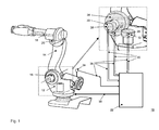
FIG. 1 shows an exemplary robot manipulator system;
FIG. 2 shows a second exemplary robot manipulator with additional devices;
FIG. 3 shows exemplary adjacent manipulator segments with heatable covers and a flexible tube;
FIG. 4 shows an exemplary sixth heatable cover with an electrical heat wire; and
FIG. 5 shows an exemplary seventh heatable cover arranged as flexible tube.
DETAILED DESCRIPTION
An exemplary robot manipulator system is disclosed wherein at least one heatable cover is attached onto at least one manipulator segment for applying heat energy thereon. An associated amount of heat energy is controlled by a control unit dependent on measured temperature values of at least one temperature sensor.
Exemplary embodiments can include applying heat energy onto specified areas (e.g., the most temperature critical areas) of the robot system by one or more heatable covers, so that a minimum operational temperature of associated components (e.g., critical components) can be ensured. Those components can be related to the robot manipulator and the robot arm itself, for example the motors, and gears including gear oil or breaks. Depending on the construction of the robot manipulator, some of those components can be seen as part of a stiff robot manipulator segment if they are directly mounted thereon, for example a motor drive. A heatable cover can have for example a flat, mat-like shape. It can be assumed, that in those cases an attached heatable cover does not reduce the freedom of movement of the robot manipulator. Since the heatable covers can be easily attachable onto those surface areas of a standard robot, which are representing or at least covering a temperature critical component, an easy solution for enabling a robot operating in a cold environment is provided.
On the other hand, there can be temperature critical components such as bearings and some parts of the hinged joints for example, which are not directly related to one stiff robot manipulator segment, since they are arranged moveable or pivotable in between different manipulator segments. Hence in some cases it might be not possible to attach a heatable cover directly on those parts—as an outer surface covering those parts—without reducing the freedom of movement of the robot arm. In those cases the heatable covers can be attached to one or more of the adjacent stiff robot manipulator segments, so that heat energy applied thereon is transferred to the adjacent temperature critical components, whereas the freedom of movement of the robot manipulator is not negatively reduced. Such a kind of heat transfer is rather efficient, since the relevant parts such as bearings or gears may be built of metal, which has a good heat conductance characteristic.
Heatable covers might be attached on several outer surface areas of the robot manipulator, such as in close proximity to the temperature critical components. A control mechanism can regulate the amount of heat energy, which is applied by one or more heatable covers onto one or more robot manipulator segments, dependent on a measured temperature. The measured temperature of one or more robot manipulator segments can be used as a controlled process variable, so that this measured temperature can be regulated to a certain value. It is on the other hand also possible to apply a predetermined amount of heat energy dependent on a measured ambient temperature. Of course it is possible to have different mechanisms or regulation characteristics for different heatable covers. According to exemplary embodiments, the amount of heat energy to be applied can be controlled and determined by a control unit. In an exemplary embodiment, this could be in an electrical circuit, but also for example a separate computing device. Furthermore, the heatable covers need not only be active in a case where a movement program is executed. The heatable covers can also be—at least temporarily—active when the robot is in a stand-by or wait mode.
According to an exemplary embodiment, this control or regulation functionality can be integrated within the robot controller, which can execute a robot program by controlling and coordinating the movement of the robot manipulator dependent on the associated robot program. The task of controlling, regulating, and determining heat energy which is applied by the heatable covers can be dependent on a measured temperature as an add-on functionality which can be implemented without additional hardware into the existing robot controller.
A robot controller can include a computing device and power amplifiers for the drives of the different robot manipulator segments, whereas the power amplifiers might be seen as an optional part of the robot controller. In a comparable way power amplifiers or such can be provided for driving the heat generation within the heatable covers according to the demand of the robot controller.
The robot controller can be connected to the robot manipulator with a control cable of a length of for example several meters, whereas a length of for example several tens of meters, or any desired cable, is also possible. Since the robot controller can be a temperature critical electronic component, it can be placed in a protected environment with a less critical temperature in a certain distance to the robot manipulator, for example in a control room. An exemplary maximum distance within a cold (e.g., freezer) room or such might amount to, for example, some ten meters, so that the length of an associated control cable is adaptable thereto.
In a further exemplary embodiment, an additional device can be mounted on the robot manipulator with an additional heatable cover attached thereon. Such an additional device can be specific to the working task of the robot manipulator system and can be a camera, a headlight, a gripper or such. The control of the heat energy, which is applied by the additional heatable cover, can be integrated into the robot controller. Hence additional temperature critical device components, which are not part of the robot manipulator itself, are easily enabled for operation in a cold environment.
In an exemplary embodiment of the robot manipulator system, at least one heatable cover can comprise an electrical heater, for example a heat wire. The amount of heat energy applied by an electrical heater can be easily regulated by electrical amplifiers whereas electrical cables are guidable along the robot manipulator arm without major restrictions in freedom of movement. Furthermore an electrical heater does not cause an exhaust emission within the working environment of the robot manipulator.
According to a further exemplary embodiment, at least one heatable cover can comprise a thermal insulating outer layer for thermal insulation of the environment. Hence the amount of heat energy to be applied by the heatable cover can be reduced where less heat energy disappears to the environment.
In another variant embodiment, at least one heatable cover can comprise a thermal conducting inner layer for heat energy distribution towards the manipulator segments. This can be useful especially for example where the robot manipulator segments are not as heat conductive; for example, those which are built from a compound material. Thus the heat energy can be applied in a homogenous way.
Following a further exemplary embodiment, at least one heatable cover can be glued onto an outer surface area of an associated manipulator segment. Thus, an intermediate space in between a heatable cover and a surface of a robot manipulator segment can be reduced in an advantageous way so that the flow of heat energy can be increased. Furthermore a heatable cover can be easily and durably attached to a robot manipulator segment.
According to another exemplary variant, at least one heatable cover can be lashed or strapped onto an outer surface area of an associated manipulator segment with a belt-like device. This enables on one hand an increased heat energy flow into the robot manipulator segment due to a minimized intermediate space. On the other hand this kind of attached heatable cover can be easy to disassemble, can provide increased flexibility and provide a better possibility for maintenance. The same advantages can also be gained by using a heatable cover, which can be designed and configured as a solvable pressure collar.
According to an exemplary variant, heatable covers can be attached on at least two adjacent manipulator segments which are linked together by a common hinged joint. A heatable cover is in some cases not directly attachable on a hinged joint, because it could reduce the freedom of movement of the robot arm in a broader way. This can enable an increased indirect heat transfer into the area around the hinged joint.
In a further exemplary embodiment, a flexible tube can be included in between the heatable covers attached on the adjacent manipulator segments which surround the common hinged joint and at least a part of the heatable covers. Such a tube can have an effect to thermally insulate an area around the hinged joint, so that less indirect transferred heat energy disappears to the environment. Such a flexible tube can partly be comparable with tights, for example concerning the material. But of course other materials can be used including but not limited to an elastic rubber material.
In an exemplary embodiment, the robot manipulator system includes a heatable cover attached as a flexible tube around a hinged joint, whereas the heatable cover can comprise a wire-like heating element that is arranged in the form of a helix or meander mainly crosswise to the longitudinal extension of the hinged joint. This kind of flexible tube is different relative to the aforementioned kind, because a more or less fixed cross section circumference can be desired due to the wire-like heating element having a sectional length that is nearly constant. Because the heating wire can be arranged in a helix- or meander-like manner crosswise to the longitudinal extension of the hinged joint, the heatable cover can be bendable along the longitudinal extension of the hinged joint. The heat dissipation around a hinged joint can also be reduced in an advantageous way, as it is possible to actively apply heat energy into this area.
In an exemplary embodiment, an attached heatable cover can comprise a sensor on its outer side for measuring ambient temperature and/or a sensor on its inner side for measuring the temperature of a covered area of an associated manipulator segment of the additional device, where it can be attached. The integration of temperature sensors into a heatable cover can provide an easier overall handling of the robot system because a separate mounting of temperature sensors can be avoided therewith. Of course an inner sensor can be thermally insulated against the environment and an outer sensor can be thermally insulated against the robot manipulator segment where the heatable cover is mounted. The data connection in between the sensor and robot controller can for example comprise a wireless section. This can simplify once again an arrangement of a sensor.
According to a further exemplary variant of the robot manipulator system, the amount of heat energy to be applied by the at least one heatable cover can depend as well on the measured values of the ambient temperature and the measured values of the temperature of at least one manipulator segment. Thus it is possible to have a stronger feedback of a measured temperature within a control loop at lower ambient temperatures than at not as low ambient temperatures. The higher dissipation of heat energy into the environment at lower ambient temperatures can be compensated therewith.
In an exemplary variant, several heatable covers can be attached onto the robot manipulator. Those can comprise associated temperature sensors on their inner side, which can provide values of measured temperatures to an evaluation device. This device can be used to determine the lowest measured temperature therefrom, whereas the determined value of the lowest temperature can be provided to the robot controller. This exemplary worst case observation can increase the reliability of the temperature control, as an exemplary most disadvantageous temperature value can be the base for applying heat energy by the heatable covers. Such a lowest-value-determination can be integrated into the robot controller, but it is also possible to do this in a separate device.
In another exemplary embodiment, the robot controller can be configured to reduce a movement speed as planned while executing a robot program in case that the measured temperature values of the at least one temperature sensor are lower than a predetermined limit. The gear of a robot manipulator segment for example is sometimes arranged within a box filled with gear oil, and oil can be a temperature critical substance. An exemplary intermediate temperature range of the oil in between an absolute uncritical upper temperature and an absolute critical lower temperature can be rather broad, for example in between 10° C. and −10° C. By reducing the movement speed of the robot manipulator while executing the robot program, the material stress for the gear can also be reduced, so that an operation with reduced speed can be enabled at a lower temperature within this intermediate temperature range. An exemplary robot program can include different sections of a predetermined movement path with different given movement speeds. A speed reduction could either be realized by a downscaling of each movement speed by a certain factor or a by a kind of speed limiter. Both functionalities are implementable within the robot controller itself. While executing the robot movement at a reduced speed the gear oil will be heated by friction, so that after applying certain friction energy the oil temperature can rise to an uncritical value.
The same effect can be gained according to another exemplary variant, whereas the robot controller can be configured to execute at least temporarily a steady motion robot program if no further robot program is foreseen for execution. This steady motion program can, for example, determine a robot motion, which loads all gears and all associated drives of all robot manipulator segments in a homogenous manner. So additional friction heat can be applied homogenously and a cooling down of a robot manipulator for the associated gear components within an off-duty state can be avoided in an advantageous way.
FIG. 1 shows an exemplary robot manipulator system 10. An exemplary robot manipulator comprises a kinematic chain of several stiff robot manipulator segments 12, 14, 16, which are linked together by hinged joints 18, 20. The robot manipulator can comprise stiff robot manipulator segments and hinged joints (without reference number), whereas an exemplary total of five degrees of freedom in movement of the robot manipulator can be considered. A robot controller 22 is connected to the robot manipulator by a connection cable 36. The robot controller can comprise a computing device and some electrical amplifiers, which drive is associated with electrical motors for each stiff robot manipulator segment. A robot program can be stored within a memory of the robot controller, whereas the robot controller determines each desired revolution of each electrical motor, so that in the end the tip of the robot manipulator performs the desired movement according to the robot program.
An ambient temperature sensor 24 can be mounted on a chassis of a spring cylinder for damping a pivoting movement. The sensor 24 is connected to the robot controller 22 by a data connection line 38. Based on a measured temperature value the robot controller 22 determines an amount of heat energy to be applied on heatable covers 30, 32, 34, which are shown in a detailed drawing. Of course, in an exemplary embodiment the heatable covers 30, 32, 34 are not limited to being only active in the case where a movement program is executed. The heatable covers can also be active when for example, the robot is in a stand-by or wait mode.
The heatable cover 30 can be attached to the outer surface of the chassis of an electrical motor drive for pivoting a part of the robot arm, whereas the heatable cover 32 can be attached to the outer surface of the chassis of an electrical motor drive for rotating the robot arm around its base. The heatable cover 34 is attached to the outer surface of a gearbox which is partly filled with gear oil. All heatable covers 30, 32, 34 can comprise on their inner side—face to the associated surface area of the robot manipulator— temperature sensors 26, 27, 28 for measuring the temperature of the robot manipulator segments to which they are attached. A data connection 38 can be included to provide measured temperature values to the robot controller 22. A common data connection and/or an—at least in part—wireless data connection can be provided. The heatable covers 30, 32, 34 can each comprise a heat wire as a heater which is driven by the robot controller 22 over the connection lines 40, in this case an electrical cable. Therefore the robot controller can comprise amplifiers for driving the heaters.
FIG. 2 shows a second robot manipulator with additional devices in a drawing 50, where an associated robot controller is not shown. The robot manipulator can comprise a kinematic chain of stiff robot manipulator segments 52, 54, 56 which are connected with hinged joints 58, 60. A gripper tool 62 can be attached to the tip of the robot manipulator, which is turnable around an axis of rotation. Furthermore the kinematic chain mentioned herein can be turnable around the robot base. In an exemplary embodiment, a total of five degrees of freedom in movement are provided for the movement of the gripper 62. A first additional device 64 (e.g., a camera), is attached to the stiff robot manipulator segment 56, of the upper robot arm. Thus the camera 64 has a good position to observe the working area of the gripper 62 in each position of the robot manipulator. This can be important for example to check if a workpiece has been gripped correctly. A second additional device 68 (e.g., a headlight), is attached to the stiff robot manipulator segment 52. Thus the working range of the robot manipulator can be illuminated such that sufficient light for the camera 64 is provided. To enable the functionality of the camera 64 and the headlight 68 also under cold environmental frame conditions, associated heatable covers 66, 70 are attached onto the associated additional devices 64, 68. Those additional heatable covers 66, 70 can also be controlled by the robot controller.
FIG. 3 shows a schematic detail drawing 80 of exemplary adjacent manipulator segments 81, 82 with attached heatable covers 86, 88 and a surrounding flexible tube 96. A common hinged joint 84 pivotably connects both manipulator segments 81, 82. Even the hinged joint 84 can be assumed to be a temperature critical component. A heatable cover is not directly connected to the parts of the hinged joint 84, as it could reduce its freedom of movement. Thus heat energy is applicable with the heatable covers 86, 88 onto the adjacent manipulator segments 81, 82, which as such are not temperature critical. Therefore the temperature in the segment areas surrounded by the heatable covers will increase compared to the lower ambient temperature, whereas temperature areas 102 and 106 with a first temperature will rise. The heat energy applied thereon can dissipate on one hand to the outer temperature areas 100 and 108. On the other hand, the applied heat is conducted by the robot manipulator segments themselves to the area around the hinged joint 84, where a temperature area 104 with a second temperature arises. Due to dissipation of heat energy from this area 104 to the environment, the second temperature is lower than the first temperature. To reduce the amount of dissipating heat energy, the flexible tube 96 can be provided. This is for example made of a stretchable material which can avoid air exchange in between a surrounded intermediate space 98 and the environment. According to an exemplary embodiment, the first temperature within the temperature areas 102, 106 can be increased such that the temperature area 104 around the hinged joint is sufficiently high for an uncritical operation.
The heatable covers 86, 88 can for example comprise three layers, whereas the inner layer can be built of a heat conductible material. In this example this feature is optional, as the robot manipulator segments 81, 82 can be built from a metal, which is a good head conductor. A medium layer—in the drawing in white colour—can be a thermal insulation against the environment, which can reduce an associated heat dissipation. Such a layer could be made from a solid foam material for example. A third outer layer—for example a kind of foil—can provide mechanical protection against mechanical impacts from outside. A not shown heat wire can be included for applying heat energy within the heatable cover which can, for example, be arranged in between the inner and the medium layer. Thus the heat energy from the heat wires can be easily applicable onto the robot manipulator segments 81, 82, whereas a thermal insulation against the environment can be provided. Sensors 92, 94 for measuring the temperature of the associated robot manipulator segments are as well integrated into the heatable covers 86, 88, and a sensor 90 for measuring the ambient temperature can be integrated on the outer side of the heatable cover 86. Those sensors are foreseen to be connected to an associated robot controller.
FIG. 4 shows an exemplary sixth heatable cover 122 with an electrical heat wire 124 in a drawing 120. The heatable cover 122 can comprise two not shown flat layers, an inner one which is a good heat conductor and a second one which is thermally insulating, whereas the heat wire 124 is arranged in between them. To apply heat energy homogenously within the heated cover, the heat wire 124 can be arranged in a meander-like manner. A temperature sensor 126 can be integrated in the heatable cover 122.
FIG. 5 shows an exemplary seventh heatable cover arranged as a flexible tube 132 around an axis of rotation 136. An integrated heat wire 134 surrounds the axis of rotation in a helix-like form. A not shown hinged joint with a longitudinal extension along the axis of rotation 136 can be surrounded by the flexible tube 132. Due to the helix-like arrangement of the heat wire 134, the flexible tube is bendable in the direction of pivoting of the hinged joint, as indicated in the sketch with reference number 138.
It will be appreciated by those skilled in the art that the present invention can be embodied in other specific forms without departing from the spirit or essential characteristics thereof. The presently disclosed embodiments are therefore considered in all respects to be illustrative and not restricted. The scope of the invention is indicated by the appended claims rather than the foregoing description and all changes that come within the meaning and range and equivalence thereof are intended to be embraced therein.
LIST OF REFERENCE SIGNS
    • 10 exemplary robot manipulator system
    • 12 first stiff manipulator segment of first manipulator
    • 14 second stiff manipulator segment of first manipulator
    • 16 third stiff manipulator segment of first manipulator
    • 18 first hinged joint of first manipulator
    • 20 second hinged joint of first manipulator
    • 22 robot controller
    • 24 ambient temperature sensor
    • 26 temperature sensor of first heatable cover
    • 27 temperature sensor of third heatable cover
    • 28 temperature sensor of second heatable cover
    • 30 first heatable cover
    • 32 second heatable cover
    • 34 third heatable cover
    • 36 connection for controlling the manipulator
    • 38 data connection for measured values from temperature sensors
    • 40 connection for heaters
    • 50 second robot manipulator with additional devices
    • 52 first stiff manipulator segment of second manipulator
    • 54 second stiff manipulator segment of second manipulator
    • 56 third stiff manipulator segment of second manipulator
    • 58 first hinged joint of second manipulator
    • 60 second hinged joint of second manipulator
    • 62 gripper
    • 64 first additional device
    • 66 heatable cover attached to first additional device
    • 68 second additional device
    • 70 heatable cover attached to second additional device
    • 80 adjacent manipulator segments with heatable covers and flexible tube
    • 81 first adjacent manipulator segment
    • 82 second adjacent manipulator segment
    • 84 common hinged joint
    • 86 forth heatable cover attached to first adjacent manipulator segment
    • 88 fifth heatable cover attached to second adjacent manipulator segment
    • 90 temperature sensor on outer side of forth heatable cover
    • 92 temperature sensor on inner side of forth heatable cover
    • 94 temperature sensor on inner side of fifth heatable cover
    • 96 flexible tube
    • 98 intermediate space surrounded by flexible tube
    • 100 first temperature area
    • 102 second temperature area
    • 104 third temperature area
    • 106 forth temperature area
    • 108 fifth temperature area
    • 110 direction of pivoting
    • 120 sixth heatable cover with electrical heat wire
    • 122 cover
    • 124 heat wire arranged in form of a meander
    • 126 temperature sensor of sixth heatable cover
    • 130 seventh heatable cover arranged as flexible tube
    • 132 cover
    • 134 heat wire arranged in form of a helix
    • 136 axis of rotation
    • 138 bending directions of the tube

Claims (16)

The invention claimed is:
1. Robot manipulator system, comprising:
a robot manipulator with a kinematic chain of stiff robot manipulator segments, which are linked together by hinged joints;
a robot controller for controlling robot manipulator movement via execution of a robot program;
at least one temperature sensor for providing measured temperature values;
at least one heatable cover attached onto at least one manipulator segment for applying heat energy thereon and attached on at least two adjacent manipulator segments which are linked together by a common hinged joint;
a control unit for controlling an amount of heat energy dependent on measured temperature values of the at least one temperature sensor; and
a flexible tube in between the heatable covers attached on the adjacent manipulator segments, which surrounds the common hinged joint and at least a part of the heatable covers.
2. Robot manipulator system according to claim 1, wherein the control unit is part of the robot controller.
3. Robot manipulator system according to claim 1, comprising:
an additional device mounted on the robot manipulator; and
an additional heatable cover attached on the additional device.
4. Robot manipulator system according to claim 1, wherein the at least one heatable cover comprises:
a thermal insulating outer layer for thermal insulation of an environment.
5. Robot manipulator system according to claim 1, wherein the at least one heatable cover comprises:
a thermal conducting inner layer for heat energy distribution towards the manipulator segments.
6. Robot manipulator system according to claim 1, wherein the robot controller is configured to reduce a movement speed as planned while executing a robot program when a measured temperature value of the at least one temperature sensor is lower than a predetermined limit.
7. Robot manipulator system according to claim 1, wherein the robot controller is configured to execute a steady motion robot program when no further robot program is selected for execution.
8. Robot manipulator system according to claim 1, comprising:
an additional device mounted on the robot manipulator; and
an additional heatable cover attached on the additional device.
9. Robot manipulator system according to claim 1, wherein the at least one heatable cover comprises:
an electrical heater.
10. Robot manipulator system, comprising:
a robot manipulator with a kinematic chain of stiff robot manipulator segments, which are linked together by hinged joints;
a robot controller for controlling robot manipulator movement via execution of a robot program;
at least one temperature sensor for providing measured temperature values;
at least one heatable cover attached onto at least one manipulator segment for applying heat energy thereon; and
a control unit for controlling an amount of heat energy dependent on measured temperature values of the at least one temperature sensor,
wherein the heatable cover is attached as a flexible tube around a hinged joint, where the heatable cover comprises:
a wire-like heating element that is arranged as a helix or meander mainly crosswise to a longitudinal extension of the hinged joint.
11. Robot manipulator system according to claim 10, wherein the at least one heatable cover comprises:
an electrical heater.
12. Robot manipulator system according to claim 11, comprising:
several heatable covers attached onto the robot manipulator, which include associated temperature sensors on their inner side to provide values of measured temperatures to an evaluation device for determining a lowest measured temperature therefrom, whereas a value of the lowest measured temperature will be provided to the robot controller.
13. Robot manipulator system according to claim 10, comprising:
heatable covers attached on at least two adjacent manipulator segments which are linked together by a common hinged joint.
14. Robot manipulator system, comprising:
a robot manipulator with a kinematic chain of stiff robot manipulator segments, which are linked together by hinged joints;
a robot controller for controlling robot manipulator movement via execution of a robot program;
at least one temperature sensor for providing measured temperature values;
at least one heatable cover attached onto at least one manipulator segment for applying heat energy thereon;
a control unit for controlling an amount of heat energy dependent on measured temperature values of the at least one temperature sensor;
an additional device mounted on the robot manipulator; and
an additional heatable cover attached on the additional device,
wherein an attached heatable cover comprises:
a sensor on its outer side for measuring an ambient temperature and/or a sensor on its inner side for measuring temperature of a covered area of an associated manipulator segment of the additional device.
15. Robot manipulator system according to claim 14, wherein the control unit is configured such that an amount of heat to be applied by the at least one heatable cover will depend on measured values of the ambient temperature and measured values of the temperature of at least one manipulator segment.
16. Robot manipulator system according to claim 14, comprising:
several heatable covers attached onto the robot manipulator, which include associated temperature sensors on their inner side to provide values of measured temperatures to an evaluation device for determining a lowest measured temperature therefrom, whereas a value of the lowest measured temperature will be provided to the robot controller.
US13/907,053 2010-12-01 2013-05-31 Robot manipulator system Active 2031-02-20 US9085084B2 (en)

Applications Claiming Priority (1)

Application Number Priority Date Filing Date Title
PCT/EP2010/007274 WO2012072093A1 (en) 2010-12-01 2010-12-01 Robot manipulator system

Related Parent Applications (1)

Application Number Title Priority Date Filing Date
PCT/EP2010/007274 Continuation WO2012072093A1 (en) 2010-12-01 2010-12-01 Robot manipulator system

Publications (2)

Publication Number Publication Date
US20130268117A1 US20130268117A1 (en) 2013-10-10
US9085084B2 true US9085084B2 (en) 2015-07-21

Family

ID=44351621

Family Applications (1)

Application Number Title Priority Date Filing Date
US13/907,053 Active 2031-02-20 US9085084B2 (en) 2010-12-01 2013-05-31 Robot manipulator system

Country Status (5)

Country Link
US (1) US9085084B2 (en)
EP (1) EP2646206B1 (en)
CN (1) CN103384585B (en)
ES (1) ES2536308T3 (en)
WO (1) WO2012072093A1 (en)

Cited By (2)

* Cited by examiner, † Cited by third party
Publication number Priority date Publication date Assignee Title
US10160119B2 (en) * 2016-03-30 2018-12-25 Fanuc Corporation Robot system
US20190159553A1 (en) * 2017-11-28 2019-05-30 Pou Chen Corporation Roughing System

Families Citing this family (11)

* Cited by examiner, † Cited by third party
Publication number Priority date Publication date Assignee Title
CN103192380A (en) * 2013-04-18 2013-07-10 岳强 Robot gripper
KR101481278B1 (en) * 2013-06-11 2015-01-09 현대자동차주식회사 Multi-functional robot apparatus for common use
DE102014219719B4 (en) * 2014-09-29 2018-05-03 Ipr Intelligente Peripherien Für Roboter Gmbh needle grippers
CN105081635A (en) * 2015-08-31 2015-11-25 江苏新光数控技术有限公司 Wheel type rotating precise machining welding robot
CN106426285A (en) * 2016-10-21 2017-02-22 上海春雨自动化设备防护技术有限公司 Temperature controlling device for robot protective clothing
US10296482B2 (en) * 2017-03-07 2019-05-21 Honeywell International Inc. System and method for flexible connection of redundant input-output modules or other devices
DE102018204184A1 (en) * 2018-03-19 2019-09-19 Leoni Kabel Gmbh Method for monitoring a supply system of a robot
DE102018206019B4 (en) * 2018-04-19 2021-01-21 Kuka Deutschland Gmbh Robot system and method for operating the robot system
DE102018208668B4 (en) * 2018-05-31 2020-09-17 Fraunhofer-Gesellschaft zur Förderung der angewandten Forschung e.V. System for at least regionally regulating a temperature of an industrial robot and method for increasing the working accuracy of an industrial robot
CN109917830A (en) * 2019-03-29 2019-06-21 徐州华恒机器人系统有限公司 Temperature control equipment and method
CN113134849A (en) * 2021-04-29 2021-07-20 成都卡诺普自动化控制技术有限公司 Automatic preheating method for robot in low-temperature environment

Citations (27)

* Cited by examiner, † Cited by third party
Publication number Priority date Publication date Assignee Title
JPS62292390A (en) 1986-06-09 1987-12-19 工業技術院長 Robot having heat control function
US5172950A (en) * 1988-04-29 1992-12-22 Fraunhofer Gesellschaft Zur Forderung Der Angewandten Forschung E.V. Micromanipulator for gripping objects
US5212432A (en) * 1989-10-20 1993-05-18 Tokico, Ltd. Industrial robot
US6184504B1 (en) * 1999-04-13 2001-02-06 Silicon Thermal, Inc. Temperature control system for electronic devices
US6304803B1 (en) * 1999-09-22 2001-10-16 Honda Giken Kogyo Kabushiki Kaisha HVAC control system for an automobile
US6505098B1 (en) * 1999-10-29 2003-01-07 Sony Corporation Robot system, robot device, and its cover
US6617845B1 (en) * 2000-04-28 2003-09-09 Rockwell Automation Technologies, Inc. Proximity sensor resistant to environmental effects
US6754560B2 (en) * 2000-03-31 2004-06-22 Sony Corporation Robot device, robot device action control method, external force detecting device and external force detecting method
US6975028B1 (en) * 2003-03-19 2005-12-13 Delta Design, Inc. Thermal apparatus for engaging electronic device
US6993922B2 (en) * 2001-05-31 2006-02-07 Delta Design, Inc. Apparatus and method for controlling the temperature of an electronic device under test
US7017358B2 (en) * 2003-03-19 2006-03-28 Delta Design, Inc. Apparatus and method for controlling the temperature of an electronic device
JP2007061962A (en) 2005-08-31 2007-03-15 Yaskawa Electric Corp Mobile robot and temperature adjustment device and method therefor
US20070089557A1 (en) * 2004-09-30 2007-04-26 Solomon Todd R Multi-ply strap drive trains for robotic arms
US20080011904A1 (en) * 2005-05-06 2008-01-17 United States Of America As Represented By The Administrator Of The Nasa Method and Associated Apparatus for Capturing, Servicing, and De-Orbiting Earth Satellites Using Robotics
US20080023460A1 (en) * 2006-07-26 2008-01-31 Petatech International Co., Ltd. Garment with heating assembly
US20080067163A1 (en) * 2006-07-20 2008-03-20 Hyperion Innovations, Inc. Heated clothing for pets
US20080147239A1 (en) * 2006-12-14 2008-06-19 Industrial Technology Research Institute Apparatus with Surface Information Displaying and Interaction Capability
US20080223844A1 (en) * 2007-03-16 2008-09-18 Cronn Charles E Textile Based Heating Apparatus and Method
US20080257094A1 (en) * 2007-04-20 2008-10-23 Gm Global Technology Operations, Inc. Method for robotic handling using thermo-reversible dry adhesives
US20090055019A1 (en) * 2007-05-08 2009-02-26 Massachusetts Institute Of Technology Interactive systems employing robotic companions
US7511443B2 (en) * 2002-09-26 2009-03-31 Barrett Technology, Inc. Ultra-compact, high-performance motor controller and method of using same
US20090145671A1 (en) * 2007-01-05 2009-06-11 Irobot Corporation Robotic Vehicle with Dynamic Range Actuators
US20090326714A1 (en) * 2006-12-05 2009-12-31 Robert Oliver Buckingham Robotic Arms
WO2010022991A1 (en) 2008-08-27 2010-03-04 Abb Research Ltd. A robot for harsh outdoor environment
US20100080733A1 (en) * 2001-08-10 2010-04-01 Symyx Technologies, Inc. Needle assembly for aspirating and dispensing from sealed containers
US20100116081A1 (en) * 2008-11-11 2010-05-13 Intuitive Surgical, Inc. Robotic linkage
US7914521B2 (en) * 1996-02-20 2011-03-29 Intuitive Surgical Operations, Inc. Method and apparatus for performing minimally invasive cardiac procedures

Family Cites Families (3)

* Cited by examiner, † Cited by third party
Publication number Priority date Publication date Assignee Title
JPH03136789A (en) * 1989-10-20 1991-06-11 Tokico Ltd Explosion proof structure of motor-operated robot
JPH03256684A (en) * 1990-03-05 1991-11-15 Hitachi Ltd Robot control device
JP5264308B2 (en) * 2008-06-12 2013-08-14 三菱電機株式会社 Control device

Patent Citations (28)

* Cited by examiner, † Cited by third party
Publication number Priority date Publication date Assignee Title
JPS62292390A (en) 1986-06-09 1987-12-19 工業技術院長 Robot having heat control function
US5172950A (en) * 1988-04-29 1992-12-22 Fraunhofer Gesellschaft Zur Forderung Der Angewandten Forschung E.V. Micromanipulator for gripping objects
US5212432A (en) * 1989-10-20 1993-05-18 Tokico, Ltd. Industrial robot
US7914521B2 (en) * 1996-02-20 2011-03-29 Intuitive Surgical Operations, Inc. Method and apparatus for performing minimally invasive cardiac procedures
US6184504B1 (en) * 1999-04-13 2001-02-06 Silicon Thermal, Inc. Temperature control system for electronic devices
US6304803B1 (en) * 1999-09-22 2001-10-16 Honda Giken Kogyo Kabushiki Kaisha HVAC control system for an automobile
US6505098B1 (en) * 1999-10-29 2003-01-07 Sony Corporation Robot system, robot device, and its cover
US6754560B2 (en) * 2000-03-31 2004-06-22 Sony Corporation Robot device, robot device action control method, external force detecting device and external force detecting method
US6617845B1 (en) * 2000-04-28 2003-09-09 Rockwell Automation Technologies, Inc. Proximity sensor resistant to environmental effects
US6993922B2 (en) * 2001-05-31 2006-02-07 Delta Design, Inc. Apparatus and method for controlling the temperature of an electronic device under test
US20100080733A1 (en) * 2001-08-10 2010-04-01 Symyx Technologies, Inc. Needle assembly for aspirating and dispensing from sealed containers
US7511443B2 (en) * 2002-09-26 2009-03-31 Barrett Technology, Inc. Ultra-compact, high-performance motor controller and method of using same
US6975028B1 (en) * 2003-03-19 2005-12-13 Delta Design, Inc. Thermal apparatus for engaging electronic device
US7017358B2 (en) * 2003-03-19 2006-03-28 Delta Design, Inc. Apparatus and method for controlling the temperature of an electronic device
US20070089557A1 (en) * 2004-09-30 2007-04-26 Solomon Todd R Multi-ply strap drive trains for robotic arms
US20080011904A1 (en) * 2005-05-06 2008-01-17 United States Of America As Represented By The Administrator Of The Nasa Method and Associated Apparatus for Capturing, Servicing, and De-Orbiting Earth Satellites Using Robotics
JP2007061962A (en) 2005-08-31 2007-03-15 Yaskawa Electric Corp Mobile robot and temperature adjustment device and method therefor
US20080067163A1 (en) * 2006-07-20 2008-03-20 Hyperion Innovations, Inc. Heated clothing for pets
US20080023460A1 (en) * 2006-07-26 2008-01-31 Petatech International Co., Ltd. Garment with heating assembly
US20090326714A1 (en) * 2006-12-05 2009-12-31 Robert Oliver Buckingham Robotic Arms
US20080147239A1 (en) * 2006-12-14 2008-06-19 Industrial Technology Research Institute Apparatus with Surface Information Displaying and Interaction Capability
US20090145671A1 (en) * 2007-01-05 2009-06-11 Irobot Corporation Robotic Vehicle with Dynamic Range Actuators
US20080223844A1 (en) * 2007-03-16 2008-09-18 Cronn Charles E Textile Based Heating Apparatus and Method
US20080257094A1 (en) * 2007-04-20 2008-10-23 Gm Global Technology Operations, Inc. Method for robotic handling using thermo-reversible dry adhesives
US20090055019A1 (en) * 2007-05-08 2009-02-26 Massachusetts Institute Of Technology Interactive systems employing robotic companions
WO2010022991A1 (en) 2008-08-27 2010-03-04 Abb Research Ltd. A robot for harsh outdoor environment
US20110154934A1 (en) 2008-08-27 2011-06-30 ABB Research Ltd........ Robot for harsh outdoor environment
US20100116081A1 (en) * 2008-11-11 2010-05-13 Intuitive Surgical, Inc. Robotic linkage

Non-Patent Citations (1)

* Cited by examiner, † Cited by third party
Title
International Search Report (PCT/ISA/210) issued on Aug. 29, 2011, by the European Patent Office as the International Searching Authority for International Application No. PCT/EP2010/007274.

Cited By (2)

* Cited by examiner, † Cited by third party
Publication number Priority date Publication date Assignee Title
US10160119B2 (en) * 2016-03-30 2018-12-25 Fanuc Corporation Robot system
US20190159553A1 (en) * 2017-11-28 2019-05-30 Pou Chen Corporation Roughing System

Also Published As

Publication number Publication date
ES2536308T3 (en) 2015-05-22
US20130268117A1 (en) 2013-10-10
CN103384585A (en) 2013-11-06
CN103384585B (en) 2016-08-10
EP2646206A1 (en) 2013-10-09
EP2646206B1 (en) 2015-03-04
WO2012072093A1 (en) 2012-06-07

Similar Documents

Publication Publication Date Title
US9085084B2 (en) Robot manipulator system
US20220003297A1 (en) Screw Actuator for a Legged Robot
US7974739B2 (en) System and method having arm with cable passage through joint to infrared lamp
US9701029B2 (en) Manipulator
US11920649B2 (en) Transmission with integrated overload protection for a legged robot
US20120215358A1 (en) Robotic arm system
JP7176330B2 (en) robot
GB2522113A (en) Wind turbine
EP2101961B1 (en) Robotic arm with sensor for an environemental parameter
US20190248021A1 (en) Motor and Controller Integration for a Legged Robot
GB2454721A (en) Controlling the translation and orientation of a moveable platform with six-degrees-of--freedom
EP3067606B1 (en) Valve system
CN110202545B (en) Auxiliary driving unit and six-degree-of-freedom parallel mechanism comprising same
JP2017216863A (en) Motor unit and robot
CN110573307A (en) Robot limb
KR102442544B1 (en) Robot assembly and robot actuating device including the same
US20240019237A1 (en) Active thermal management for coordinate measuring machines
JP6852880B2 (en) SCARA robot
CN220809617U (en) Rail transport robot for transporting high-resistance carbon film plates
US20230202058A1 (en) Cooling medium flow path structure, cooler, robot, and method of mounting cooler to robot
JP6255904B2 (en) robot
WO2015024579A1 (en) Robot manipulated viewpoint
JP2018034279A (en) robot

Legal Events

Date Code Title Description
AS Assignment

Owner name: ABB AG, GERMANY

Free format text: ASSIGNMENT OF ASSIGNORS INTEREST;ASSIGNORS:STAAB, HARALD;KOCK, SONKE;SIGNING DATES FROM 20130521 TO 20130628;REEL/FRAME:030832/0157

FEPP Fee payment procedure

Free format text: PAYOR NUMBER ASSIGNED (ORIGINAL EVENT CODE: ASPN); ENTITY STATUS OF PATENT OWNER: LARGE ENTITY

STCF Information on status: patent grant

Free format text: PATENTED CASE

MAFP Maintenance fee payment

Free format text: PAYMENT OF MAINTENANCE FEE, 4TH YEAR, LARGE ENTITY (ORIGINAL EVENT CODE: M1551); ENTITY STATUS OF PATENT OWNER: LARGE ENTITY

Year of fee payment: 4

MAFP Maintenance fee payment

Free format text: PAYMENT OF MAINTENANCE FEE, 8TH YEAR, LARGE ENTITY (ORIGINAL EVENT CODE: M1552); ENTITY STATUS OF PATENT OWNER: LARGE ENTITY

Year of fee payment: 8