US9027558B2 - Headgear connection assembly for a respiratory mask assembly - Google Patents
Headgear connection assembly for a respiratory mask assembly Download PDFInfo
- Publication number
- US9027558B2 US9027558B2 US14/269,768 US201414269768A US9027558B2 US 9027558 B2 US9027558 B2 US 9027558B2 US 201414269768 A US201414269768 A US 201414269768A US 9027558 B2 US9027558 B2 US 9027558B2
- Authority
- US
- United States
- Prior art keywords
- locking
- locking clip
- frame
- assembly
- clip
- Prior art date
- Legal status (The legal status is an assumption and is not a legal conclusion. Google has not performed a legal analysis and makes no representation as to the accuracy of the status listed.)
- Active
Links
- 230000000241 respiratory effect Effects 0.000 title claims abstract description 19
- 210000001061 forehead Anatomy 0.000 description 25
- 210000003811 finger Anatomy 0.000 description 13
- 230000000712 assembly Effects 0.000 description 5
- 238000000429 assembly Methods 0.000 description 5
- 230000008901 benefit Effects 0.000 description 4
- 239000007789 gas Substances 0.000 description 4
- 239000000463 material Substances 0.000 description 4
- 238000004519 manufacturing process Methods 0.000 description 3
- 230000014759 maintenance of location Effects 0.000 description 2
- 230000029058 respiratory gaseous exchange Effects 0.000 description 2
- 230000004075 alteration Effects 0.000 description 1
- 230000015572 biosynthetic process Effects 0.000 description 1
- 230000000295 complement effect Effects 0.000 description 1
- 230000008878 coupling Effects 0.000 description 1
- 238000010168 coupling process Methods 0.000 description 1
- 238000005859 coupling reaction Methods 0.000 description 1
- 239000003517 fume Substances 0.000 description 1
- 239000003292 glue Substances 0.000 description 1
- 238000001746 injection moulding Methods 0.000 description 1
- 230000007246 mechanism Effects 0.000 description 1
- 238000000034 method Methods 0.000 description 1
- 238000012986 modification Methods 0.000 description 1
- 230000004048 modification Effects 0.000 description 1
- 229920000728 polyester Polymers 0.000 description 1
- 230000008569 process Effects 0.000 description 1
- 238000006467 substitution reaction Methods 0.000 description 1
- 210000003813 thumb Anatomy 0.000 description 1
- 238000009423 ventilation Methods 0.000 description 1
Images


Classifications
-
- A—HUMAN NECESSITIES
- A61—MEDICAL OR VETERINARY SCIENCE; HYGIENE
- A61M—DEVICES FOR INTRODUCING MEDIA INTO, OR ONTO, THE BODY; DEVICES FOR TRANSDUCING BODY MEDIA OR FOR TAKING MEDIA FROM THE BODY; DEVICES FOR PRODUCING OR ENDING SLEEP OR STUPOR
- A61M16/00—Devices for influencing the respiratory system of patients by gas treatment, e.g. mouth-to-mouth respiration; Tracheal tubes
- A61M16/06—Respiratory or anaesthetic masks
- A61M16/0683—Holding devices therefor
-
- A—HUMAN NECESSITIES
- A44—HABERDASHERY; JEWELLERY
- A44B—BUTTONS, PINS, BUCKLES, SLIDE FASTENERS, OR THE LIKE
- A44B11/00—Buckles; Similar fasteners for interconnecting straps or the like, e.g. for safety belts
- A44B11/25—Buckles; Similar fasteners for interconnecting straps or the like, e.g. for safety belts with two or more separable parts
- A44B11/26—Buckles; Similar fasteners for interconnecting straps or the like, e.g. for safety belts with two or more separable parts with push-button fastenings
- A44B11/266—Buckles; Similar fasteners for interconnecting straps or the like, e.g. for safety belts with two or more separable parts with push-button fastenings with at least one push-button acting parallel to the main plane of the buckle and perpendicularly to the direction of the fastening action
-
- A—HUMAN NECESSITIES
- A61—MEDICAL OR VETERINARY SCIENCE; HYGIENE
- A61M—DEVICES FOR INTRODUCING MEDIA INTO, OR ONTO, THE BODY; DEVICES FOR TRANSDUCING BODY MEDIA OR FOR TAKING MEDIA FROM THE BODY; DEVICES FOR PRODUCING OR ENDING SLEEP OR STUPOR
- A61M16/00—Devices for influencing the respiratory system of patients by gas treatment, e.g. mouth-to-mouth respiration; Tracheal tubes
- A61M16/06—Respiratory or anaesthetic masks
- A61M16/0605—Means for improving the adaptation of the mask to the patient
- A61M16/0633—Means for improving the adaptation of the mask to the patient with forehead support
- A61M16/0638—Means for improving the adaptation of the mask to the patient with forehead support in the form of a pivot
-
- A—HUMAN NECESSITIES
- A61—MEDICAL OR VETERINARY SCIENCE; HYGIENE
- A61M—DEVICES FOR INTRODUCING MEDIA INTO, OR ONTO, THE BODY; DEVICES FOR TRANSDUCING BODY MEDIA OR FOR TAKING MEDIA FROM THE BODY; DEVICES FOR PRODUCING OR ENDING SLEEP OR STUPOR
- A61M16/00—Devices for influencing the respiratory system of patients by gas treatment, e.g. mouth-to-mouth respiration; Tracheal tubes
- A61M16/06—Respiratory or anaesthetic masks
- A61M16/0605—Means for improving the adaptation of the mask to the patient
- A61M16/0633—Means for improving the adaptation of the mask to the patient with forehead support
- A61M16/0644—Means for improving the adaptation of the mask to the patient with forehead support having the means for adjusting its position
- A61M16/065—Means for improving the adaptation of the mask to the patient with forehead support having the means for adjusting its position in the form of a pivot
-
- A—HUMAN NECESSITIES
- A61—MEDICAL OR VETERINARY SCIENCE; HYGIENE
- A61M—DEVICES FOR INTRODUCING MEDIA INTO, OR ONTO, THE BODY; DEVICES FOR TRANSDUCING BODY MEDIA OR FOR TAKING MEDIA FROM THE BODY; DEVICES FOR PRODUCING OR ENDING SLEEP OR STUPOR
- A61M16/00—Devices for influencing the respiratory system of patients by gas treatment, e.g. mouth-to-mouth respiration; Tracheal tubes
- A61M16/08—Bellows; Connecting tubes ; Water traps; Patient circuits
- A61M16/0816—Joints or connectors
- A61M16/0825—Joints or connectors with ball-sockets
-
- Y—GENERAL TAGGING OF NEW TECHNOLOGICAL DEVELOPMENTS; GENERAL TAGGING OF CROSS-SECTIONAL TECHNOLOGIES SPANNING OVER SEVERAL SECTIONS OF THE IPC; TECHNICAL SUBJECTS COVERED BY FORMER USPC CROSS-REFERENCE ART COLLECTIONS [XRACs] AND DIGESTS
- Y10—TECHNICAL SUBJECTS COVERED BY FORMER USPC
- Y10T—TECHNICAL SUBJECTS COVERED BY FORMER US CLASSIFICATION
- Y10T24/00—Buckles, buttons, clasps, etc.
- Y10T24/45—Separable-fastener or required component thereof [e.g., projection and cavity to complete interlock]
- Y10T24/45225—Separable-fastener or required component thereof [e.g., projection and cavity to complete interlock] including member having distinct formations and mating member selectively interlocking therewith
- Y10T24/45471—Projection having movable connection between components thereof or variable configuration
- Y10T24/45524—Projection having movable connection between components thereof or variable configuration including resiliently biased projection component or surface segment
- Y10T24/45529—Requiring manual force applied against bias to interlock or disengage
-
- Y—GENERAL TAGGING OF NEW TECHNOLOGICAL DEVELOPMENTS; GENERAL TAGGING OF CROSS-SECTIONAL TECHNOLOGIES SPANNING OVER SEVERAL SECTIONS OF THE IPC; TECHNICAL SUBJECTS COVERED BY FORMER USPC CROSS-REFERENCE ART COLLECTIONS [XRACs] AND DIGESTS
- Y10—TECHNICAL SUBJECTS COVERED BY FORMER USPC
- Y10T—TECHNICAL SUBJECTS COVERED BY FORMER US CLASSIFICATION
- Y10T24/00—Buckles, buttons, clasps, etc.
- Y10T24/45—Separable-fastener or required component thereof [e.g., projection and cavity to complete interlock]
- Y10T24/45225—Separable-fastener or required component thereof [e.g., projection and cavity to complete interlock] including member having distinct formations and mating member selectively interlocking therewith
- Y10T24/45471—Projection having movable connection between components thereof or variable configuration
- Y10T24/45524—Projection having movable connection between components thereof or variable configuration including resiliently biased projection component or surface segment
- Y10T24/45545—Projection having movable connection between components thereof or variable configuration including resiliently biased projection component or surface segment forming total external surface of projection
- Y10T24/45581—Projection having movable connection between components thereof or variable configuration including resiliently biased projection component or surface segment forming total external surface of projection having inserted end formed by oppositely biased surface segments
Definitions
- the present invention relates to a headgear connection assembly for use in removably attaching a headgear assembly to a frame of a respiratory mask assembly, the mask assembly being used for treatment, e.g., of Sleep Disordered Breathing (SDB) with Non-invasive Positive Pressure Ventilation (NPPV).
- SDB Sleep Disordered Breathing
- NPPV Non-invasive Positive Pressure Ventilation
- Respiratory mask assemblies used in the treatment of SDB may comprise a nasal mask designed to fit over a patient's nose, or a full face mask designed to fit over the nose and mouth of the patient. Air or other breathable gas is supplied by a blower and passed along a flexible conduit to the mask assembly.
- the mask assembly generally comprises a relatively rigid shell, e.g., a frame, which defines a rearwardly opening cavity covering the patient's nose and/or mouth, and a soft portion, e.g., a cushion, which spaces the frame away from the face of the patient for comfortable contact.
- a relatively rigid shell e.g., a frame
- a soft portion e.g., a cushion
- the mask assembly is usually held in place using a headgear assembly, the frame and headgear assembly being joined using some form of connector.
- Some patients have poor dexterity, and hence find certain arrangements of connectors awkward or difficult to use. For example, some patients may have difficulty in correctly joining the frame and headgear assembly with the connector. As a result, the connector may disengage during use or may become stuck so it becomes difficult for the patient to disconnect the frame from the headgear assembly.
- some connectors are positioned on the frame of the mask assembly which makes it difficult for the user to see the connectors, because they are very close to the eyes or out of the range of vision of the patient.
- One aspect of the present invention is to provide a respiratory mask assembly having a headgear connection assembly positioned between the frame and headgear assembly in a convenient and intuitive location for quick attachment and/or detachment by the patient, while not being easily detached accidentally.
- the respiratory mask assembly includes a frame and at least one locking clip.
- the frame has a main body and a side frame member provided on each lateral side of the main body.
- At least one of the side frame members includes an integrally formed locking clip receiver assembly.
- the at least one locking clip has a main body providing a front portion and a rear portion. The front portion is adapted to be removably coupled with the at least one locking clip receiver assembly and the rear portion is adapted to be removably coupled to a headgear assembly.
- the rear portion of the locking clip includes a cross bar that forms an opening through which a strap of the headgear assembly can pass and be removably coupled with the cross bar, and the front portion of the locking clip includes at least one resiliently flexible spring arm that is flexible within the plane of the main body.
- Another aspect of the invention is to provide a headgear connection assembly which can be easily molded in a mask frame which includes a swivel elbow connector.
- Another aspect of the invention is to provide a locking clip that includes a flexing spring arm having a length that is effectively increased while maintaining a compact size, without sacrificing spring/clip retention forces.
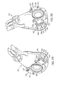
- FIG. 1 is a front perspective view illustrating a mask assembly having a headgear connection assembly constructed in accordance with an embodiment of the invention
- FIG. 2 is a front view of the mask assembly showing FIG. 1 ;
- FIG. 3 is a top view of a locking clip of the headgear connection assembly shown in FIG. 1 ;
- FIG. 4 is a perspective view of a locking clip of the headgear connection assembly shown in FIG. 1 ;
- FIG. 5 is a perspective view of a locking clip receiver assembly of the headgear connection assembly shown in FIG. 1 ;
- FIG. 6 is a front view of a locking clip receiver assembly of the headgear connection assembly shown in FIG. 1 ;
- FIG. 7 is a cross-sectional view of a locking clip receiver assembly of the headgear connection assembly shown in FIG. 1 ;
- FIG. 8 is a cross-sectional view illustrating the engagement between a locking clip and a locking clip receiver assembly of the headgear connection assembly shown in FIG. 1 ;
- FIG. 9 is a cross-sectional view illustrating the engagement between a locking clip and a locking clip receiver assembly of the headgear connection assembly shown in FIG. 1 ;
- FIG. 10 is a perspective view illustrating the mask assembly of FIG. 1 being secured to a patient's face by a headgear connection assembly of FIG. 1 ;
- FIG. 11 is a top view illustrating the headgear connection assembly of FIG. 1 in a first incorrect position with respect to the frame of the mask assembly;
- FIG. 12 is a top view illustrating the headgear connection assembly of FIG. 1 in a second incorrect position with respect to the frame of the mask assembly;
- FIG. 13 is a front perspective view of a locking clip of the headgear connection assembly shown in FIG. 1 ;
- FIG. 14 is a rear perspective view of the locking clip shown in FIG. 13 ;
- FIG. 15 is a top view of the locking clip shown in FIG. 13 ;
- FIG. 16 is a cross-section taken along line 16 - 16 of FIG. 15 ;
- FIG. 17 is a front view of the locking clip shown in FIG. 13 ;
- FIG. 18 is a rear view of the locking clip shown in FIG. 13 ;
- FIG. 19 is a side view of the locking clip shown in FIG. 13 ;
- FIG. 20 is a bottom view of the locking clip shown in FIG. 13 ;
- FIG. 21 is a front perspective view of another embodiment of a locking clip
- FIG. 22 is a rear perspective view of the locking clip shown in FIG. 21 ;
- FIG. 23 is a top view of the locking clip shown in FIG. 21 ;
- FIG. 24 is a cross-section taken along line 24 - 24 of FIG. 23 ;
- FIG. 25 is a front view of the locking clip shown in FIG. 21 ;
- FIG. 26 is a rear view of the locking clip shown in FIG. 21 ;
- FIG. 27 is a side view of the locking clip shown in FIG. 21 ;
- FIG. 28 is a bottom view of the locking clip shown in FIG. 21 ;
- FIG. 29 is a front perspective view illustrating an embodiment of a frame for a full-face mask assembly, the frame having a locking clip receiver assembly structured to interlock with the locking clip shown in FIG. 21 ;
- FIG. 30 is a front perspective view, similar to FIG. 29 but at a different angle, of the frame shown in FIG. 29 ;
- FIG. 31 is a rear perspective view of the frame shown in FIG. 29 ;
- FIG. 32 is a front view of the frame shown in FIG. 29 ;
- FIG. 33 is a side view of the frame shown in FIG. 29 ;
- FIG. 34 is a top view of the frame shown in FIG. 29 ;
- FIG. 35 is a top perspective view illustrating an embodiment of a forehead support adapted to be movably mounted to an upper portion of the frame shown in FIG. 29 , the forehead support having a locking clip receiver assembly structured to interlock with the locking clip shown in FIG. 21 ;
- FIG. 36 is a rear perspective view of the forehead support shown in FIG. 35 ;
- FIG. 37 is a front perspective view of the forehead support shown in FIG. 35 ;
- FIG. 38 is a front view of the forehead support shown in FIG. 35 ;
- FIG. 39 is a side view of the forehead support shown in FIG. 35 ;
- FIG. 40 is a top view of the forehead support shown in FIG. 35 ;
- FIG. 41 is a front view of a locking clip according to another embodiment of the present invention.
- FIG. 42 is a rear view thereof
- FIG. 43 is a front perspective view thereof.
- FIG. 44 is a front view of a locking clip according to another embodiment of the present invention.
- FIG. 45 is a rear view thereof
- FIG. 46 is a front perspective view thereof
- FIG. 47 is a front view Of a locking clip according to another embodiment of the present invention.
- FIG. 48 is a rear view thereof
- FIG. 49 is a front perspective view thereof.
- FIG. 50 is a side view thereof.
- FIGS. 1 and 2 shown a respiratory mask assembly 10 that includes a frame 12 and a cushion 14 that may be permanently or removably connected to the frame 12 .
- the cushion 14 may be removably attached to the frame 12 with a cushion clip, straps, a friction or interference fit, and/or a tongue-in-groove arrangement, as is known in the art.
- the cushion 14 may be permanently attached to the frame 12 with glue and/or mechanical fastening means, for example.
- a forehead support 16 is movably mounted to an upper portion of the frame 12 .
- a headgear assembly (not shown) can be removably attached to the frame 12 to maintain the frame 12 and cushion 14 in a desired adjusted position on the patient's face.
- the headgear assembly may include a pair of upper and lower straps with the upper straps removably connected to clip structures 18 provided on the forehead support 16 and the lower straps removably connected the frame 12 by a headgear connection assembly 20 , as will be further discussed below.
- the mask assembly 10 is a nasal mask structure to deliver breathable gas to a patient's nose.
- the mask assembly 10 may be a nasal and mouth mask, or the mask assembly may be a full face mask.
- a swivel elbow assembly 22 is removably attached to a front portion of the frame 12 .
- the elbow assembly 22 is structured to be connected to a conduit that is connected to a pressurized supply.
- the pressurized supply supplies pressurized breathable gas through the conduit and elbow assembly 22 and into the cushion 14 for breathing by the patient.
- lower straps of the headgear assembly are removably attached to the frame 12 by a headgear connection assembly 20 .
- the headgear connection assembly 20 includes a first connector portion 24 provided by the frame 12 and a second connector portion 26 adapted to be removably coupled with the first connector portion 24 .
- the second connector portion 26 is removably connected to the lower straps of the headgear assembly.
- the second connector portion 26 includes a pair of locking clips 28 .
- the locking clip 28 is a unitary plastic piece formed by injection molding.
- each locking clip 28 includes a main body 30 having a rear portion 32 and a front portion 34 .
- the rear portion 32 is removably connected to a lower strap of the headgear assembly and the front portion 34 is removably coupled with the first connector portion 24 provided on the frame 12 .
- the front portion 34 includes at least one and preferably two resiliently flexible spring arms 36 that are attached to opposite sides of the main body 30 and extend away from the main body 30 in a generally parallel manner.
- the front portion 34 may include one spring arm 36 .
- the spring arms 36 can flex up and down, e.g., in the direction of arrows A or in a reverse direction of arrows A, respectively, as shown in FIG. 3 .
- a locking tab 38 is attached to a free end of each spring arm 36 .
- each spring arm 36 is configured to provide a shoulder portion 40 .
- the shoulder portions 40 and locking tabs 38 are adapted to engage with corresponding portions of the first connector portion 24 for coupling the first and second connector portions 24 , 26 with one another.
- the locking tabs 38 are structured to prevent accidental disengagement of the second connector portion 26 from the first connector portion 24 if a force is applied to the second connector portion 26 in the direction of arrow B ( FIG. 3 ), as will be further discussed.
- the front portion 32 also includes a central support tab 42 positioned between the pair of spring arms 36 .
- the central support tab 42 has a length that is greater than the length of each of the spring arms 36 .
- the central support tab 42 is slidably insertable into a complimentary shaped portion of the first connector portion 24 , as will be further discussed.
- the central support tab 42 includes a groove 44 .
- the central support tab 42 has a height of h 2
- the front portion of each spring arm 36 has a height of h 1 .
- the height h 2 is larger than the height h 1 .
- h 2 may be smaller than h 1 .
- the rear portion 32 of the second connector portion 26 includes a cross bar 46 that forms an opening 48 through which a lower strap of the headgear assembly may pass and be removably connected. Specifically, an end portion of the lower strap of the headgear assembly may be wrapped around the cross bar 46 . Fastening of the lower strap to the cross bar 46 may be assisted by use of a hook and loop material, such as Velcro®. Thus, the lower strap may be adjusted with respect to the locking clip 28 for proper fit.
- the locking clip 28 may be rotatably adjustable with respect to the headgear assembly, e.g., see U.S. Provisional Application No. 60/402,509, filed on Aug., 12, 2002, incorporated herein by reference in its entirety.
- the frame 12 includes a main body 50 accommodating the cushion 14 and a side frame member 52 provided on each lateral side of the main body 50 .
- Each side frame member 52 includes the first connector portion 24 which is integrally formed therewith.
- the first connector portion 24 includes a locking clip receiver assembly 54 .
- the locking clip 28 is structured to interlock with the locking clip receiver assembly 54 to removably attach the locking clip 28 , and hence the headgear assembly, to the frame 12 .
- Each locking clip receiver assembly 54 includes a slot 56 having a central portion 58 and two locking portions 60 positioned on opposite sides of the central portion 58 .
- the central portion 58 of the slot 56 has an upper surface 62 that is continuous with an upper surface 64 of each of the locking portions 60 .
- lower surfaces 66 , 68 of the central portion 58 and two locking portions 60 respectively, have a stepped configuration.
- the central portion 58 has a height h 2 between the upper surface 62 and lower surface 66 thereof.
- the two locking portions 60 have a height h 1 between the upper surface 64 and lower surface 68 thereof. In the illustrated embodiment, the height h 2 is greater than the height h 1 .
- the height h 2 of the central portion 58 is approximately equal to the height h 2 of the central support tab 42 and the height h 1 of the two locking portions 60 is approximately equal to the height h 1 of the front portion of each spring arm 36 .
- This arrangement facilitates the connection between the locking clip 28 and the locking clip receiver assembly 54 , as will be further discussed.
- each of the locking portions 60 includes a locking flange 70 positioned on an outer wall thereof for engagement with the locking tab 38 of a locking clip 28 .
- the central portion 58 includes a wall 72 that extends upwardly from the lower surface 66 towards the upper surface 62 .
- the wall 72 extends approximately half the way to the upper surface 62 .
- the first connector portions 24 are integrally molded with the frame 12 .
- the frame 12 also includes an orifice 80 and collar 82 adapted to receive a swivel elbow 22 ( FIGS. 1 and 2 ).
- the collar 82 has a rim 84 which extends horizontally and radially from the orifice 80 .
- the mold can be withdrawn horizontally.
- the headgear be presented at an angle with respect to the frame 12 .
- the first connector portions 24 are aligned downwardly at an angle ⁇ of approximately 5% with respect to the horizontal.
- the mold components When the frame 12 is molded, the mold components should be withdrawn in a horizontal direction to form the collar 82 .
- the junction between the lower surfaces 66 , 68 of the central portion 58 and locking portions 60 , respectively, is arranged to make an angle ⁇ which is sufficiently wide to enable the sides of the mold to be withdrawn in a horizontal direction. Further, the angled junction facilitates the connection between the locking clip 28 and the locking clip receiver assembly 54 .
- the front portion 34 and rear portion 32 of the locking clip 28 are disposed at an angle ⁇ with respect to one another.
- the rear portion 34 is angled downwardly with respect to the horizontal, whereas the front portion 32 is generally horizontally aligned.
- the headgear straps are connected to the locking clip 28 at an angle which more naturally follows the contour of the face.
- the front and rear portions 34 , 32 may be curved to achieve an angular difference between the front and rear.
- slot 56 of the first connector portion 24 into which the front portion 34 of the second connector 26 is slidably received may be generally horizontal. This is advantageous during the manufacture process because it means the sides of the mold may be withdrawn horizontally to assist formation of the collar 82 .
- the locking portions 60 of the slot 56 are adapted to receive a respective one of the pair of spring arms 36 , the locking tab 38 of each spring arm 36 interlocking with the locking flange 70 provided in respective locking portions 60 to removably attach the locking clip 28 , and hence the headgear. assembly, to the frame 12 .
- the shoulder portion 40 of each locking clip 28 engages an engagement face 74 provided on the fume 12 when the locking clip 28 is inserted into the locking clip receiver assembly 54 to provide additional support for the locking clip 28 .
- the locking tab 38 may interlock with an undercut provided in the locking portions 60 to removably attach the locking clip 28 to the frame 12 .
- each locking tab 38 may extend through a slot provided in the outer wall of the locking portion 60 . The slot need not extend through the outer wall of the locking portion 60 .
- the central support tab 42 is inserted into the central portion 58 of the slot 56 when the locking clip 28 and locking clip receiver assembly 54 are engaged so as to prevent relative movement between the locking clip 28 and the locking clip receiver assembly 54 .
- the spring arms 36 are forced toward one another (in the direction of arrows A as shown in FIG. 3 ) as the locking tabs 38 are inserted into respective locking portions 60 of the slot 56 and ride up and over the locking flanges 70 .
- the spring arms 36 can spring outwardly (in the reverse direction of arrows A as shown in FIG. 3 ) to provide a locking engagement between the locking tabs 38 and the locking flanges 70 .
- Sufficient clearance is provided in the locking portions 60 of the slot 56 to allow the necessary movement of the locking tabs 38 to clear the locking flanges 70 .
- the central support tab 42 is configured to have a close fit with the central portion 58 of the slot 56 so that when the central support tab 42 is inserted into the central portion 58 , little rotational, rocking or side-to-side movement is permitted between the locking clip 28 and the locking clip receiver assembly 54 .
- the central support tab 42 is longer than the spring arms 36 to assist with alignment into the slot 56 .
- the groove 44 of the central support tab 42 engages the wall 72 provided in the central portion 58 of the slot 56 to facilitate entry of the central support tab 42 into the central portion 58 of the slot 56 .
- the central support tab 42 may have a protrusion that engages a groove provided in the central portion 58 of the slot 56 .
- the central support tab 42 has a shape that is complementary to the angle ⁇ that defines the shape of the central portion 58 of the slot 56 .
- the locking portions 60 of the slot 56 are of sufficient height to accommodate the front portion of each spring arm 36 , but insufficient to accommodate the central support tab 42 . That is, the central support tab 42 is too thick to fit into the locking portions 60 of the slot 56 . Because of this arrangement, it will be clear to the patient whether or not the locking clip 28 has been correctly engaged with the locking clip receiver assembly 54 . Thus, the patient cannot inadvertently partly assemble the locking clip 28 to the locking clip receiver assembly 54 in such a way that it will accidentally release. For example, FIG.
- FIG. 11 illustrates a first incorrect position of the locking clip 28 with respect to the locking clip receiver assembly 54
- FIG. 12 illustrates a second incorrect position of the locking clip 28 with respect to the locking clip receiver assembly 54 .
- the patient is unable to insert the thicker central support tab 42 into the thinner locking portion 60 of the slot 56 .
- the patient To release the locking clip 28 from the locking clip receiver assembly 54 , the patient simply forces the spring arms 36 towards one another to clear the locking tabs 38 from respective locking flanges 70 . Then, the patient pulls the locking clip 28 outwardly away from the frame 12 to disengage the locking clip 28 from the locking clip receiver assembly 54 .
- the locking tabs 38 and central support tab 42 have rounded or contoured edges to facilitate entry into the slot 56 .
- the outward surfaces of the locking clip 28 and the frame 12 preferably form a generally coextensive continuous surface, which is not interrupted when connected.
- the locking clip 28 is as wide as the side frame members 52 , which facilitates tactile location of the locking clip 28 by the patient.
- the spring arms 36 are designed to flex within the plane of the locking clip main body 30 , which further improves the ease by which the locking clips 28 are attached and detached. This positioning improves the ergonomics of flexing the spring arms up and down. As shown in FIG. 10 , the patient's thumb and opposing finger can be used to readily locate and operate the locking clips 28 .
- the outward surface of the spring arms 36 may include a series of protrusions 76 to facilitate gripping of the locking clip 28 by the patient (see FIG. 8 ). Further, the locking clips 28 are connected to the straps of the headgear assembly so that length adjustment may be provided.
- headgear connection assembly 20 An advantage of the headgear connection assembly 20 is that one locking clip 28 can be used with the locking clip receiver assembly 54 provided on each side frame member 52 , thereby reducing manufacturing costs and the need for inventory.
- FIGS. 13-20 show further structural details in various dimensions in one embodiment of the locking clip 28 of the headgear connection assembly 20 .
- the locking clip 28 has a length in the range of 20-40 mm, preferably 29 mm, a width in the range of 20-40 mm, preferably 27.8 mm, and a height in the range of 4-8 mm, preferably 6.7 mm.
- the dimensions illustrated in FIGS. 13-20 may vary ⁇ 10%.
- the rear portion 32 of the locking clip 28 includes a cross-bar 46 that forms an opening 48 through which a strap of the headgear assembly can be removably coupled with the cross-bar 46 .
- the strap of the headgear assembly is connected using other mechanisms.
- the strap may include a hook which engages with a corresponding hole in the locking clip.
- the strap is sewn in position and is not removable.
- the strap is removable, and held in position by a friction fit.
- a locking clip in accordance with the invention is used only on a mask frame adjacent a swivel elbow, in the region of the mouth; and straps for connection to a forehead support of the mask assembly are held in position only by hook & loop material.
- two locking clips are used on one mask.
- four locking clips are used, two as illustrated, and a further two being used as part of the forehead support.
- FIGS. 21-28 illustrate another embodiment of a locking clip, indicated as 228 .
- the locking clip 228 is structured for use with a full-face mask assembly having a frame 212 (see FIGS. 29-34 ) and a forehead support 216 (see FIGS. 35-40 ).
- the frame 212 has a pair of locking clip receiver assemblies 254 structured to interlock with a pair of locking clips 228 .
- the forehead support 216 has a pair of locking clip receiver assemblies 254 structured to interlock with a pair of locking clips 228 .
- the locking clip 228 and locking clip receiver assemblies 254 illustrated may be structured for use with a nasal mask or a nasal and mouth mask, for example.
- the locking clip 228 is substantially similar to the locking clip 28 described above.
- the length of the groove 244 provided in clip 228 is greater than the length of the groove 44 provided in clip 28 , as will be further discussed.
- the remaining elements of the locking clip 228 are similar to the elements of the locking clip 28 and are indicated with similar reference numerals.
- the locking clip 228 includes a main body 230 having a rear portion 232 and a front portion 234 .
- the rear portion 232 is removably connected to a strap of the headgear assembly and the front portion 234 is removably coupled with a respective locking clip receiver assembly 254 provided on the frame 212 or forehead support 216 .
- the front portion 234 includes two resiliently flexible spring arms 236 that are attached to opposite sides of the main body 230 .
- the flexible spring arms 236 are flexible within the plane of the main body 230 .
- each spring arm 236 includes a locking tab 238 and a shoulder portion 240 adapted to engage with a respective locking clip receiver assembly 254 provided on the frame 212 or forehead support 216 .
- the front portion 234 also includes a central support tab 242 that includes a groove 244 .
- the groove 244 provided in clip 228 is deeper or more elongated than the groove 44 provided in clip 28 (as best shown in FIGS. 14 and 22 ).
- the groove 244 has a length that is at least half a length of the central support tab 242 .
- the elongated groove in clip 228 facilitates with alignment of the clip 228 with the frame 212 or forehead support 216 .
- the elongated groove 244 helps to prevent relative movement between the locking clip 228 and the respective locking clip receiver assembly 254 on the frame 212 or forehead support 216 , as will be further discussed below.
- FIGS. 29-34 show an embodiment of a frame 212 for a full-face mask assembly.
- the frame 212 may be permanently or removably connected to a cushion (not shown) in any suitable manner. Further, a swivel elbow assembly (not shown) may be removable attached to a front portion of the frame 212 .
- Each lateral side of the frame 212 includes a locking clip receiver assembly 254 structured to interlock with a locking clip 228 .
- the locking clip receiver assembly 254 includes a slot 256 having a central portion 258 and two locking portions 260 .
- the locking portions 260 include a locking flange 270 (see FIG. 32 ) positioned on an outer wall thereof for engagement with the locking tab 238 of a locking clip 228 .
- an upper wall 261 of the slot 256 includes a pair of openings 263 that are aligned with the locking flange 270 . This enables the patient to visually confirm that the locking tab 238 of a locking clip 228 is interlocked with the locking flange 270 in use.
- the central portion 258 includes a wall 272 .
- the wall 272 provided in the locking clip receiver assembly 254 extends outwardly away from the slot 256 .
- the wall 72 was positioned entirely within the slot 56 (see FIGS. 5 , 7 , 11 , and 12 ).
- the elongated wall 272 of locking clip receiver assembly 254 facilitates alignment of a clip 228 with a respective locking clip receiver assembly 254 .
- the groove 244 of a clip 228 may be engaged with the elongated wall 272 so as to guide the clip 228 into the slot 256 .
- FIGS. 35-40 show an embodiment of a forehead support 216 adapted to be movably mounted to an upper portion of the frame 212 .
- the forehead support 216 may be provided with one or more fixed, permanent or removable forehead pads (not shown) in any suitable manner.
- Each lateral side of the forehead support 216 includes a locking clip receiver assembly 254 structured to interlock with a locking clip 228 .
- the locking clip receiver assembly 254 on the forehead support 216 is substantially similar to the locking clip receiver assembly on the frame 216 and indicated with similar reference numerals.
- one locking clip 228 can be used with the locking clip receiver assemblies 254 provided on the frame 212 and the forehead support 216 , thereby reducing manufacturing costs and the need for inventory.
- four locking clips 228 are used, two locking clips 228 for the frame 212 and two locking clips 228 for the forehead support 216 .
- upper straps of a headgear assembly would be removably connected to the locking clips 228 for the forehead support 216 and lower straps of the headgear assembly would be removably connected to locking clips 228 for the frame 212 .
- FIGS. 41-50 show additional embodiments of the present invention.
- FIGS. 41-43 show a locking clip 300 which is similar to the locking clip 228 shown in FIGS. 21-23 .
- the locking clip 300 is constructed and arranged for use with a nasal or full face mask having a locking clip receiving assembly and provided with headgear, as described above.
- locking clip 300 includes raised finger grip portions 302 which are larger than the grip portions shown, e.g., in FIG. 22 .
- Each grip portion may include one or more grooves 303 .
- the enlarged finger grip portions 302 shown in FIGS. 41-43 offer a larger grip for the fingers since they protrude and therefore allow the clip to be more easily squeezed upon assembly and disassembly.
- FIGS. 44-46 show yet another embodiment, similar to the embodiment of FIGS. 41-43 , in which a locking clip 304 includes finger grip portions 306 and grooves 307 which are even larger than the finger grip portions 302 and grooves 303 shown in FIGS. 41-43 .
- the enlarged finger grip portions shown in FIGS. 44-46 also enable easier assembly and disassembly.
- the finger grip portions 306 offer a larger grip for the fingers since they protrude and therefore allow the clip to be more easily squeezed upon disassembly.
- grip portions 302 may protrude about 1-3 mm away from flexing arms, while grip portions 306 may extend from 2-6 mm away from flexing arms.
- FIGS. 47-49 illustrate yet another embodiment of the present invention.
- Locking clip 310 includes a modified body and arm design.
- Locking clip includes a pair of flexible spring arms 312 .
- Each arm 312 includes a first end 314 including a locking tab 316 and a second end 318 , near front portion 319 of clip 304 , attached to the main body 320 .
- Each arm 312 is spaced from the main body 320 by a flexing space 322 .
- Arm 312 includes a central portion 324 that is angled with respect to proximal portion 326 of arm 312 .
- Central portion 324 is spaced by a gap 328 from rear portion 330 .
- Gaps 322 and 328 may form the general shape of the letter “L.”
- the design of the arms 312 in this manner e.g., a spring loop, allows for effective compact lengthening of the arms so as to reduce the force required to squeeze clip upon assembly and/or disassembly. This reduced force may also provide the user with a softer and/or improved feel, since the looped design allows the arm to deflect about a greater effective length, without sacrificing spring/clip retention forces.
- FIGS. 47-49 include finger grip portions like those shown in FIGS. 21-28 , but the finger grip portions shown in FIGS. 41-46 could also be used.
- FIG. 50 is a side view of clip 310 .
- FIGS. 47-50 include exemplary dimensions of clip 310 . However, the dimensional values can be changed to suit the particular application. In embodiments, the dimensions can be changed to be up to ⁇ 20%, and preferably up to ⁇ 10%, of the values shown.
- the clip 310 may be made of a polyester material, e.g., POCAN B1501, although other materials are possible.
Abstract
Description
Claims (11)
Priority Applications (1)
| Application Number | Priority Date | Filing Date | Title |
|---|---|---|---|
| US14/269,768 US9027558B2 (en) | 2001-09-07 | 2014-05-05 | Headgear connection assembly for a respiratory mask assembly |
Applications Claiming Priority (11)
| Application Number | Priority Date | Filing Date | Title |
|---|---|---|---|
| US31748601P | 2001-09-07 | 2001-09-07 | |
| US34285401P | 2001-12-28 | 2001-12-28 | |
| US10/235,846 US6823869B2 (en) | 2001-09-07 | 2002-09-06 | Mask assembly |
| US42469802P | 2002-11-08 | 2002-11-08 | |
| US46757103P | 2003-05-05 | 2003-05-05 | |
| US10/655,603 US7753050B2 (en) | 2001-09-07 | 2003-09-05 | Headgear connection assembly for a respiratory mask assembly |
| US53673504P | 2004-01-16 | 2004-01-16 | |
| PCT/AU2004/001834 WO2005068002A1 (en) | 2004-01-16 | 2004-12-24 | Headgear connection assembly for a respiratory mask assembly |
| US10/585,514 US7841345B2 (en) | 2004-01-16 | 2004-12-24 | Headgear connection assembly for a respiratory mask assembly |
| US12/805,037 US8763612B2 (en) | 2004-01-16 | 2010-07-08 | Headgear connection assembly for a respiratory mask assembly |
| US14/269,768 US9027558B2 (en) | 2001-09-07 | 2014-05-05 | Headgear connection assembly for a respiratory mask assembly |
Related Parent Applications (1)
| Application Number | Title | Priority Date | Filing Date |
|---|---|---|---|
| US12/805,037 Continuation US8763612B2 (en) | 2001-09-07 | 2010-07-08 | Headgear connection assembly for a respiratory mask assembly |
Publications (2)
| Publication Number | Publication Date |
|---|---|
| US20140238404A1 US20140238404A1 (en) | 2014-08-28 |
| US9027558B2 true US9027558B2 (en) | 2015-05-12 |
Family
ID=34794429
Family Applications (3)
| Application Number | Title | Priority Date | Filing Date |
|---|---|---|---|
| US10/585,514 Active 2027-04-11 US7841345B2 (en) | 2001-09-07 | 2004-12-24 | Headgear connection assembly for a respiratory mask assembly |
| US12/805,037 Active US8763612B2 (en) | 2001-09-07 | 2010-07-08 | Headgear connection assembly for a respiratory mask assembly |
| US14/269,768 Active US9027558B2 (en) | 2001-09-07 | 2014-05-05 | Headgear connection assembly for a respiratory mask assembly |
Family Applications Before (2)
| Application Number | Title | Priority Date | Filing Date |
|---|---|---|---|
| US10/585,514 Active 2027-04-11 US7841345B2 (en) | 2001-09-07 | 2004-12-24 | Headgear connection assembly for a respiratory mask assembly |
| US12/805,037 Active US8763612B2 (en) | 2001-09-07 | 2010-07-08 | Headgear connection assembly for a respiratory mask assembly |
Country Status (7)
| Country | Link |
|---|---|
| US (3) | US7841345B2 (en) |
| EP (1) | EP1708773A4 (en) |
| JP (2) | JP4787174B2 (en) |
| CN (2) | CN101810903B (en) |
| AU (1) | AU2004313613B2 (en) |
| NZ (2) | NZ589941A (en) |
| WO (1) | WO2005068002A1 (en) |
Cited By (1)
| Publication number | Priority date | Publication date | Assignee | Title |
|---|---|---|---|---|
| US10137273B2 (en) | 2001-11-20 | 2018-11-27 | Fisher & Paykel Healthcare Limited | Patient interfaces |
Families Citing this family (52)
| Publication number | Priority date | Publication date | Assignee | Title |
|---|---|---|---|---|
| DE20017940U1 (en) | 2000-10-19 | 2000-12-28 | Map Gmbh | Breathing mask for supplying a breathing gas to a mask user and a derivation device for deriving breathing gas |
| US7753050B2 (en) * | 2001-09-07 | 2010-07-13 | Resmed Limited | Headgear connection assembly for a respiratory mask assembly |
| DE10151984C5 (en) | 2001-10-22 | 2008-07-17 | Map Medizin-Technologie Gmbh | Application device for a breathing mask arrangement |
| WO2003035156A2 (en) | 2001-10-22 | 2003-05-01 | Map Medizin-Technologie Gmbh | Breathing mask device and application device and frontal support device thereof |
| DE10201682A1 (en) | 2002-01-17 | 2003-07-31 | Map Medizin Technologie Gmbh | The breathing mask arrangement |
| EP2594306B1 (en) | 2002-09-06 | 2015-10-21 | ResMed Limited | Forehead pad for respiratory mask |
| EP2514471B1 (en) | 2003-05-02 | 2016-01-13 | ResMed Ltd. | A mask system |
| AU2004313613B2 (en) * | 2004-01-16 | 2011-05-26 | ResMed Pty Ltd | Headgear connection assembly for a respiratory mask assembly |
| US8783257B2 (en) | 2004-02-23 | 2014-07-22 | Fisher & Paykel Healthcare Limited | Breathing assistance apparatus |
| AU2005228827C1 (en) | 2004-04-02 | 2022-02-03 | Fisher & Paykel Healthcare Limited | Breathing assistance apparatus |
| WO2005123166A1 (en) | 2004-06-16 | 2005-12-29 | Resmed Limited | Cushion for a respiratory mask assembly |
| NZ556041A (en) | 2005-01-12 | 2011-11-25 | Resmed Ltd | Forehead supports for facial masks |
| NZ565507A (en) | 2005-10-14 | 2011-06-30 | Resmed Ltd | Mask with cushion having lip which in use deflects against frame of mask |
| NZ701505A (en) | 2005-10-25 | 2016-06-24 | Resmed Ltd | Interchangeable mask assembly |
| DE202007019687U1 (en) | 2006-07-14 | 2015-07-14 | Fisher & Paykel Healthcare Ltd. | Respiratory support device |
| US8517023B2 (en) | 2007-01-30 | 2013-08-27 | Resmed Limited | Mask system with interchangeable headgear connectors |
| US11331447B2 (en) | 2008-03-04 | 2022-05-17 | ResMed Pty Ltd | Mask system with snap-fit shroud |
| NZ772129A (en) | 2008-03-04 | 2022-10-28 | ResMed Pty Ltd | Mask system |
| US10258757B2 (en) | 2008-05-12 | 2019-04-16 | Fisher & Paykel Healthcare Limited | Patient interface and aspects thereof |
| US10792451B2 (en) | 2008-05-12 | 2020-10-06 | Fisher & Paykel Healthcare Limited | Patient interface and aspects thereof |
| US11660413B2 (en) | 2008-07-18 | 2023-05-30 | Fisher & Paykel Healthcare Limited | Breathing assistance apparatus |
| WO2010041966A1 (en) | 2008-10-10 | 2010-04-15 | Fisher & Paykel Healthcare Limited | Nasal pillows for a patient interface |
| US8601617B1 (en) * | 2008-10-11 | 2013-12-10 | Advanced Basic Communications | Mounting device for attaching a device to a mask |
| US8286311B2 (en) * | 2008-10-31 | 2012-10-16 | Jisook Paik | Buckle |
| US9539403B2 (en) | 2009-08-26 | 2017-01-10 | Resmed Limited | Mask system |
| WO2011062510A1 (en) | 2009-11-18 | 2011-05-26 | Fisher & Paykel Healthcare Limited | Nasal interface |
| CN115591073A (en) * | 2009-11-20 | 2023-01-13 | 瑞思迈私人有限公司(Au) | Mask system |
| WO2011110968A2 (en) | 2010-03-12 | 2011-09-15 | Koninklijke Philips Electronics N.V. | Patient interface device with dynamic mask adjustment |
| EP4070841A1 (en) | 2010-10-08 | 2022-10-12 | Fisher & Paykel Healthcare Limited | Breathing assistance apparatus |
| EP2478926A1 (en) * | 2011-01-20 | 2012-07-25 | Air Liquide Medical Systems | Connector element for headgear of respiratory mask |
| US10603456B2 (en) | 2011-04-15 | 2020-03-31 | Fisher & Paykel Healthcare Limited | Interface comprising a nasal sealing portion |
| EP4282456A3 (en) | 2011-04-15 | 2024-02-14 | Fisher & Paykel Healthcare Limited | Interface comprising a rolling nasal bridge portion |
| WO2012156929A2 (en) * | 2011-05-17 | 2012-11-22 | Koninklijke Philips Electronics N.V. | Flexible member adjustable forehead support cross-reference to related applications |
| CN102847215B (en) * | 2011-06-30 | 2015-11-18 | 北京怡和嘉业医疗科技有限公司 | For adjusting part and the breathing mask of breathing mask |
| EP3566736B1 (en) * | 2011-07-01 | 2020-12-09 | Fisher & Paykel Healthcare Limited | Nasal mask interface assembly |
| WO2013056389A1 (en) * | 2011-10-18 | 2013-04-25 | Honeywell International Inc. | Automatically adjustable cushion of respiratory mask for better fit |
| US20140311496A1 (en) * | 2011-11-03 | 2014-10-23 | Koninklijke Philips N.V. | Patient interface having headgear post for clip or strap |
| CN203107935U (en) * | 2011-12-29 | 2013-08-07 | 皇家飞利浦电子股份有限公司 | Patient interface system with adjustable forehead supporting part |
| GB2519261B (en) | 2012-08-08 | 2018-02-28 | Fisher & Paykel Healthcare Ltd | Headgear for patient interface |
| EP4279106A3 (en) | 2012-09-04 | 2024-01-17 | Fisher & Paykel Healthcare Limited | Valsalva mask |
| GB2538016B (en) * | 2012-10-25 | 2017-05-10 | Jsp Ltd | Improvements to wearable protective device |
| GB2544428B (en) | 2014-08-25 | 2021-03-24 | Fisher & Paykel Healthcare Ltd | A cushion module for a respiratory interface |
| US11173270B2 (en) * | 2015-03-04 | 2021-11-16 | Fisher & Paykel Healthcare Limited | Mask system headgear |
| WO2016203376A1 (en) | 2015-06-18 | 2016-12-22 | Koninklijke Philips N.V. | Patient interface device and retention assembly therefor |
| USD882066S1 (en) | 2016-05-13 | 2020-04-21 | Fisher & Paykel Healthcare Limited | Frame for a breathing mask |
| US10156071B2 (en) * | 2016-08-19 | 2018-12-18 | Avigilon Corporation | Adaptor for installing a camera or lighting fixture |
| USD824020S1 (en) | 2017-02-23 | 2018-07-24 | Fisher & Paykel Healthcare Limited | Cushion assembly for breathing mask assembly |
| USD823455S1 (en) | 2017-02-23 | 2018-07-17 | Fisher & Paykel Healthcare Limited | Cushion assembly for breathing mask assembly |
| USD823454S1 (en) | 2017-02-23 | 2018-07-17 | Fisher & Paykel Healthcare Limited | Cushion assembly for breathing mask assembly |
| EP4241814A3 (en) * | 2017-12-21 | 2023-11-08 | Fisher & Paykel Healthcare Limited | Respiratory mask system |
| CN112806677B (en) * | 2020-12-31 | 2023-06-30 | 西安易朴通讯技术有限公司 | Wearable device and assembly method thereof |
| TWI803145B (en) * | 2022-01-10 | 2023-05-21 | 貝斯美德股份有限公司 | Buckle connector used for mask and headgear |
Citations (88)
| Publication number | Priority date | Publication date | Assignee | Title |
|---|---|---|---|---|
| US1081745A (en) | 1912-05-03 | 1913-12-16 | White S Dental Mfg Co | Nasal inhaler. |
| GB1146568A (en) | 1966-06-23 | 1969-03-26 | Tarwil Rosoflex | Improvements in or relating to a separable element connecting device |
| DE2323633A1 (en) | 1973-05-10 | 1974-11-28 | Reinhard Gedack | LOCKING CLAMP FOR BRUSH |
| GB2002445A (en) | 1977-08-10 | 1979-02-21 | Illinois Tool Works | Belt buckles |
| US4402316A (en) | 1981-04-27 | 1983-09-06 | U.S.D. Corp. | Breathing gas mask |
| US4414973A (en) | 1981-03-10 | 1983-11-15 | U.S.D. Corp. | Respirator face mask |
| WO1985001192A1 (en) | 1983-09-09 | 1985-03-28 | I.T.W. De France | Auxiliary element for pusher of articles such as loops, fastenersand clasps |
| GB2150632A (en) | 1983-11-30 | 1985-07-03 | Itw Ltd | Buckles |
| US4569106A (en) | 1982-03-19 | 1986-02-11 | Itw Fastex Italia S.P.A. | Buckle of the snap closure type having the two parts engageable by snap action identical to one another |
| US4577375A (en) | 1983-08-31 | 1986-03-25 | Intertechnique | Quick attachment device for harness of a piece of equipment |
| US4639982A (en) | 1982-03-23 | 1987-02-03 | Nippon Notion Kogyo Co., Ltd. | Releasable buckle |
| US4688337A (en) | 1985-12-20 | 1987-08-25 | National Molding Corporation | Buckle type fastener |
| US4712280A (en) | 1985-04-26 | 1987-12-15 | Gerhard Fildan | Strap fastener |
| US4713844A (en) | 1986-07-16 | 1987-12-22 | Gentex Corporation | Protective helmet with face mask sealing means |
| US4793032A (en) | 1986-11-28 | 1988-12-27 | Illinois Tool Works, Inc. | Side release buckle |
| US4907584A (en) | 1988-03-03 | 1990-03-13 | Mcginnis Gerald E | Respiratory mask |
| US4944310A (en) | 1981-04-24 | 1990-07-31 | Somed Pty. Ltd. | Device for treating snoring sickness |
| US4960121A (en) | 1987-03-18 | 1990-10-02 | Figgie International, Inc. | Half-face mask assembly |
| US5027481A (en) | 1990-11-01 | 1991-07-02 | Illinois Tool Works | Shell buckle |
| US5069205A (en) | 1990-04-20 | 1991-12-03 | Figgie International, Inc. | Quick-donning head harness assembly |
| EP0471264A2 (en) | 1990-08-16 | 1992-02-19 | CAIRNS & BROTHER INCORPORATED | Protective helmet with protective facepiece connection and adjustment provision |
| FR2676652A1 (en) | 1991-05-23 | 1992-11-27 | Gallet Sa | Arm for securing a breathing mask on a protective helmet |
| US5222279A (en) | 1992-07-27 | 1993-06-29 | Illinois Tool Works Inc. | Buckle having increased holding power when under load |
| US5243971A (en) | 1990-05-21 | 1993-09-14 | The University Of Sydney | Nasal mask for CPAP having ballooning/moulding seal with wearer's nose and facial contours |
| US5245995A (en) | 1987-06-26 | 1993-09-21 | Rescare Limited | Device and method for monitoring breathing during sleep, control of CPAP treatment, and preventing of apnea |
| US5441046A (en) | 1993-09-29 | 1995-08-15 | Respironics, Inc. | Quick release mechanism for nasal and/or oral gas delivery mask |
| US5465506A (en) | 1994-01-19 | 1995-11-14 | Karhu Usa Inc. | Sandal fastening system |
| JPH0822242A (en) | 1994-07-08 | 1996-01-23 | Yubitsukusu:Kk | Means for correcting and training way of holding bar to be grasped |
| US5507076A (en) | 1994-09-15 | 1996-04-16 | National Molding Corporation | Side-release buckle having improved locking feature |
| US5551131A (en) | 1994-12-15 | 1996-09-03 | National Molding Corp. | Buckle which is releasable by depression of a hinged member and having improved locking capability |
| US5555569A (en) | 1994-03-18 | 1996-09-17 | Firequip Helmets, Inc. | Helmet and face mask interface system |
| US5590444A (en) | 1994-08-02 | 1997-01-07 | American Cord & Webbing Company, Inc. | Side release buckle with improved distribution of stress under loads |
| JPH09502628A (en) | 1993-09-15 | 1997-03-18 | ミネソタ・マイニング・アンド・マニュファクチュアリング・カンパニー | Convenient "descent" type mask |
| US5657493A (en) | 1994-03-25 | 1997-08-19 | Dacor Corporation | Diving mask with quick-release strap attachment |
| US5704345A (en) | 1993-11-05 | 1998-01-06 | Resmed Limited | Detection of apnea and obstruction of the airway in the respiratory system |
| AU3081397A (en) | 1996-07-30 | 1998-02-05 | David Gareth Johnson | Knapsack sprayers and firefighters carry harness |
| WO1998012965A1 (en) | 1996-09-23 | 1998-04-02 | Resmed Limited | Assisted ventilation to match patient respiratory need |
| US5737810A (en) | 1994-08-02 | 1998-04-14 | American Cord & Webbing Co, Inc. | Side release buckle with increased holding strength |
| JPH10117814A (en) | 1996-10-08 | 1998-05-12 | American Cord & Webbing Co Inc | Side releasing buckle improve in holding strength |
| DE29723101U1 (en) | 1997-04-05 | 1998-05-28 | Weinmann G Geraete Med | Device for coupling to ventilation masks |
| US5791026A (en) | 1997-05-30 | 1998-08-11 | National Molding Corporation | Side-release buckle having retaining straps |
| US5921239A (en) | 1997-01-07 | 1999-07-13 | Sunrise Medical Hhg Inc. | Face mask for patient breathing |
| WO1999035933A1 (en) | 1998-01-16 | 1999-07-22 | Mccay Holdings Pty. Ltd. | A strap assembly |
| JPH11309004A (en) | 1998-04-30 | 1999-11-09 | Ykk Corp | Buckle |
| WO1999061088A1 (en) | 1998-05-22 | 1999-12-02 | Resmed Limited | Ventilatory assistance for treatment of cardiac failure and cheyne-stokes breathing |
| US6112746A (en) | 1996-07-26 | 2000-09-05 | Resmed Limited | Nasal mask and mask cushion therefor |
| US6119693A (en) | 1998-01-16 | 2000-09-19 | Resmed Limited | Forehead support for facial mask |
| WO2000078383A1 (en) | 1999-06-18 | 2000-12-28 | Resmed Ltd. | Mask and headgear connector |
| WO2000078384A1 (en) | 1999-06-18 | 2000-12-28 | Resmed Limited | Forehead support for facial mask |
| WO2001032250A1 (en) | 1999-11-03 | 2001-05-10 | Australian Centre For Advanced Medicine Technology Ltd | Mask |
| JP2001178506A (en) | 1999-12-16 | 2001-07-03 | Taiwan Industrial Fastener Corp | Cushion type clamp |
| US20010010778A1 (en) | 1996-10-18 | 2001-08-02 | Kevin Hilton | Fastenings |
| JP2001218606A (en) | 2000-02-10 | 2001-08-14 | Nifco Inc | Buckle |
| EP1166674A1 (en) | 2000-06-30 | 2002-01-02 | Ykk Corporation | Buckle |
| US6341710B1 (en) | 2000-10-23 | 2002-01-29 | Bcb Innovations, Inc. | Sheathed receptacle with locking means |
| JP2002051824A (en) | 2000-08-11 | 2002-02-19 | Morito Co Ltd | Hang down strap |
| US6347631B1 (en) | 1999-11-09 | 2002-02-19 | Mallinckrodt, Inc. | Cantilever device and method for breathing devices and the like |
| US20020029780A1 (en) | 2000-06-22 | 2002-03-14 | Frater Robert H. | Mask with gusset |
| AU7555901A (en) | 2000-09-27 | 2002-03-28 | Ykk Corporation | Buckle |
| US6374826B1 (en) | 1999-03-18 | 2002-04-23 | Resmed Limited | Mask and headgear connector |
| US6378466B1 (en) | 2000-10-23 | 2002-04-30 | Coastal Pet Products, Inc. | Side release buckle |
| US6412487B1 (en) | 1997-01-31 | 2002-07-02 | Resmed Limited | Mask cushion and frame assembly |
| DE10057893C1 (en) | 2000-11-22 | 2002-07-11 | Mpv Truma Ges Fuer Medizintech | Nasal breathing mask has section which fits over nose and has mounting to which a strap is attached which holds mask on, connector at top of mask linking it to breathing hose and forehead shield attached to mounting clipping on to hose |
| US6422238B1 (en) | 1999-01-12 | 2002-07-23 | Resmed Limited | Headgear |
| US20020108613A1 (en) | 1999-02-09 | 2002-08-15 | Resmed Limited | Mask cushion and frame assembly |
| US6530373B1 (en) | 2000-08-04 | 2003-03-11 | Mallinckrodt Inc. | Respirator mask |
| US6536435B1 (en) | 1999-02-22 | 2003-03-25 | Cabot Safety Intermediate Corporation | Respirator headpiece and release mechanism |
| JP2003129325A (en) | 2001-10-26 | 2003-05-08 | Meiwa Kosan Kk | Connector for helmet |
| US20030106192A1 (en) | 2000-05-02 | 2003-06-12 | Hans-Jorg Schmitz | Belt buckle |
| US20030110605A1 (en) | 2001-12-17 | 2003-06-19 | Yasutaka Nishida | Three point release buckle assembly |
| US20030135966A1 (en) | 2002-01-18 | 2003-07-24 | Masaru Tejima | Strap buckle |
| US6611965B1 (en) | 2002-12-23 | 2003-09-02 | Shu-Min Lee | Safety goggles |
| US6615460B1 (en) | 2002-08-27 | 2003-09-09 | David Baumgarten | Optionally manual or automatic breakaway lanyard buckle |
| US20030196656A1 (en) | 2002-04-23 | 2003-10-23 | Moore Rachael E. | Ergonomic and adjustable respiratory mask assembly with cushion |
| US20030196302A1 (en) | 2002-04-17 | 2003-10-23 | Buscart Jordi Badrenas | Side release buckle with spring |
| US20030196662A1 (en) | 2002-04-23 | 2003-10-23 | Ging Anthony M. | Ergonomic and adjustable respiratory mask assembly with elbow assembly |
| US20030196658A1 (en) | 2002-04-23 | 2003-10-23 | Ging Anthony M. | Ergonomic and adjustable respiratory mask assembly with frame |
| USD485905S1 (en) | 2002-08-09 | 2004-01-27 | Resmed Limited | Nasal mask |
| US20040045551A1 (en) | 2002-09-06 | 2004-03-11 | Ric Investments, Inc. | Patient interface with forehead support system |
| WO2004022144A1 (en) | 2002-09-06 | 2004-03-18 | Resmed Limited | Headgear connection assembly for a respiratory mask assembly |
| WO2003082406A3 (en) | 2002-03-22 | 2004-03-18 | Invacare Corp | Nasal mask |
| US20040112384A1 (en) | 2001-09-07 | 2004-06-17 | Resmed Limited | Headgear connection assembly for a respiratory mask assembly |
| US6823869B2 (en) | 2001-09-07 | 2004-11-30 | Resmed Limited | Mask assembly |
| US20050199240A1 (en) * | 2003-01-09 | 2005-09-15 | Matthew Hall | Flexible full-face mask for CPAP treatment |
| US7111368B2 (en) | 2002-09-20 | 2006-09-26 | Ykk Corporation | Buckle |
| US7290313B2 (en) | 2002-06-25 | 2007-11-06 | Royal College Of Art | Clasp |
| US20080066759A1 (en) | 2006-09-07 | 2008-03-20 | Resmed Limited | Headgear connection assembly |
| US20100275923A1 (en) | 2004-01-16 | 2010-11-04 | Resmed Limited | Headgear connection assembly for a respiratory mask assembly |
-
2004
- 2004-12-24 AU AU2004313613A patent/AU2004313613B2/en not_active Ceased
- 2004-12-24 NZ NZ589941A patent/NZ589941A/en unknown
- 2004-12-24 NZ NZ548484A patent/NZ548484A/en unknown
- 2004-12-24 WO PCT/AU2004/001834 patent/WO2005068002A1/en active Application Filing
- 2004-12-24 US US10/585,514 patent/US7841345B2/en active Active
- 2004-12-24 JP JP2006548034A patent/JP4787174B2/en not_active Expired - Fee Related
- 2004-12-24 EP EP04802135A patent/EP1708773A4/en not_active Withdrawn
- 2004-12-24 CN CN201010119450.4A patent/CN101810903B/en not_active Expired - Fee Related
- 2004-12-24 CN CN200480040513XA patent/CN1905918B/en not_active Expired - Fee Related
-
2010
- 2010-07-08 US US12/805,037 patent/US8763612B2/en active Active
- 2010-12-15 JP JP2010279326A patent/JP5411116B2/en not_active Expired - Fee Related
-
2014
- 2014-05-05 US US14/269,768 patent/US9027558B2/en active Active
Patent Citations (113)
| Publication number | Priority date | Publication date | Assignee | Title |
|---|---|---|---|---|
| US1081745A (en) | 1912-05-03 | 1913-12-16 | White S Dental Mfg Co | Nasal inhaler. |
| GB1146568A (en) | 1966-06-23 | 1969-03-26 | Tarwil Rosoflex | Improvements in or relating to a separable element connecting device |
| DE2323633A1 (en) | 1973-05-10 | 1974-11-28 | Reinhard Gedack | LOCKING CLAMP FOR BRUSH |
| GB2002445A (en) | 1977-08-10 | 1979-02-21 | Illinois Tool Works | Belt buckles |
| US4150464A (en) | 1977-08-10 | 1979-04-24 | Illinois Tool Works Inc. | Buckle |
| US4414973A (en) | 1981-03-10 | 1983-11-15 | U.S.D. Corp. | Respirator face mask |
| US4944310A (en) | 1981-04-24 | 1990-07-31 | Somed Pty. Ltd. | Device for treating snoring sickness |
| US4402316A (en) | 1981-04-27 | 1983-09-06 | U.S.D. Corp. | Breathing gas mask |
| US4569106A (en) | 1982-03-19 | 1986-02-11 | Itw Fastex Italia S.P.A. | Buckle of the snap closure type having the two parts engageable by snap action identical to one another |
| US4639982A (en) | 1982-03-23 | 1987-02-03 | Nippon Notion Kogyo Co., Ltd. | Releasable buckle |
| US4577375A (en) | 1983-08-31 | 1986-03-25 | Intertechnique | Quick attachment device for harness of a piece of equipment |
| WO1985001192A1 (en) | 1983-09-09 | 1985-03-28 | I.T.W. De France | Auxiliary element for pusher of articles such as loops, fastenersand clasps |
| GB2150632A (en) | 1983-11-30 | 1985-07-03 | Itw Ltd | Buckles |
| US4712280A (en) | 1985-04-26 | 1987-12-15 | Gerhard Fildan | Strap fastener |
| US4688337A (en) | 1985-12-20 | 1987-08-25 | National Molding Corporation | Buckle type fastener |
| US4713844A (en) | 1986-07-16 | 1987-12-22 | Gentex Corporation | Protective helmet with face mask sealing means |
| US4793032A (en) | 1986-11-28 | 1988-12-27 | Illinois Tool Works, Inc. | Side release buckle |
| US4960121A (en) | 1987-03-18 | 1990-10-02 | Figgie International, Inc. | Half-face mask assembly |
| US5245995A (en) | 1987-06-26 | 1993-09-21 | Rescare Limited | Device and method for monitoring breathing during sleep, control of CPAP treatment, and preventing of apnea |
| US4907584A (en) | 1988-03-03 | 1990-03-13 | Mcginnis Gerald E | Respiratory mask |
| US5069205A (en) | 1990-04-20 | 1991-12-03 | Figgie International, Inc. | Quick-donning head harness assembly |
| US5243971A (en) | 1990-05-21 | 1993-09-14 | The University Of Sydney | Nasal mask for CPAP having ballooning/moulding seal with wearer's nose and facial contours |
| EP0471264A2 (en) | 1990-08-16 | 1992-02-19 | CAIRNS & BROTHER INCORPORATED | Protective helmet with protective facepiece connection and adjustment provision |
| US5291880A (en) | 1990-08-16 | 1994-03-08 | Cairns & Brother Inc. | Protective helmet with protective facepiece connection and adjustment provision |
| US5027481A (en) | 1990-11-01 | 1991-07-02 | Illinois Tool Works | Shell buckle |
| JPH0638810A (en) | 1990-11-01 | 1994-02-15 | Illinois Tool Works Inc <Itw> | Buckle |
| FR2676652A1 (en) | 1991-05-23 | 1992-11-27 | Gallet Sa | Arm for securing a breathing mask on a protective helmet |
| US5222279A (en) | 1992-07-27 | 1993-06-29 | Illinois Tool Works Inc. | Buckle having increased holding power when under load |
| AU4178693A (en) | 1992-07-27 | 1994-02-17 | Illinois Tool Works Inc. | Buckle having increased holding power when under load |
| JPH09502628A (en) | 1993-09-15 | 1997-03-18 | ミネソタ・マイニング・アンド・マニュファクチュアリング・カンパニー | Convenient "descent" type mask |
| US5441046A (en) | 1993-09-29 | 1995-08-15 | Respironics, Inc. | Quick release mechanism for nasal and/or oral gas delivery mask |
| US5704345A (en) | 1993-11-05 | 1998-01-06 | Resmed Limited | Detection of apnea and obstruction of the airway in the respiratory system |
| US5465506A (en) | 1994-01-19 | 1995-11-14 | Karhu Usa Inc. | Sandal fastening system |
| US5555569A (en) | 1994-03-18 | 1996-09-17 | Firequip Helmets, Inc. | Helmet and face mask interface system |
| US5657493A (en) | 1994-03-25 | 1997-08-19 | Dacor Corporation | Diving mask with quick-release strap attachment |
| JPH0822242A (en) | 1994-07-08 | 1996-01-23 | Yubitsukusu:Kk | Means for correcting and training way of holding bar to be grasped |
| US5737810A (en) | 1994-08-02 | 1998-04-14 | American Cord & Webbing Co, Inc. | Side release buckle with increased holding strength |
| US5590444A (en) | 1994-08-02 | 1997-01-07 | American Cord & Webbing Company, Inc. | Side release buckle with improved distribution of stress under loads |
| US5507076A (en) | 1994-09-15 | 1996-04-16 | National Molding Corporation | Side-release buckle having improved locking feature |
| US5551131A (en) | 1994-12-15 | 1996-09-03 | National Molding Corp. | Buckle which is releasable by depression of a hinged member and having improved locking capability |
| US6112746A (en) | 1996-07-26 | 2000-09-05 | Resmed Limited | Nasal mask and mask cushion therefor |
| AU3081397A (en) | 1996-07-30 | 1998-02-05 | David Gareth Johnson | Knapsack sprayers and firefighters carry harness |
| WO1998012965A1 (en) | 1996-09-23 | 1998-04-02 | Resmed Limited | Assisted ventilation to match patient respiratory need |
| JPH10117814A (en) | 1996-10-08 | 1998-05-12 | American Cord & Webbing Co Inc | Side releasing buckle improve in holding strength |
| US20010010778A1 (en) | 1996-10-18 | 2001-08-02 | Kevin Hilton | Fastenings |
| US5921239A (en) | 1997-01-07 | 1999-07-13 | Sunrise Medical Hhg Inc. | Face mask for patient breathing |
| US6412487B1 (en) | 1997-01-31 | 2002-07-02 | Resmed Limited | Mask cushion and frame assembly |
| DE29723101U1 (en) | 1997-04-05 | 1998-05-28 | Weinmann G Geraete Med | Device for coupling to ventilation masks |
| JPH10327908A (en) | 1997-05-30 | 1998-12-15 | Natl Molding Corp | Side release buckle with holding strap |
| US5791026A (en) | 1997-05-30 | 1998-08-11 | National Molding Corporation | Side-release buckle having retaining straps |
| WO1999035933A1 (en) | 1998-01-16 | 1999-07-22 | Mccay Holdings Pty. Ltd. | A strap assembly |
| US6119693A (en) | 1998-01-16 | 2000-09-19 | Resmed Limited | Forehead support for facial mask |
| US6061883A (en) | 1998-04-30 | 2000-05-16 | Ykk Corporation | Buckle |
| JPH11309004A (en) | 1998-04-30 | 1999-11-09 | Ykk Corp | Buckle |
| WO1999061088A1 (en) | 1998-05-22 | 1999-12-02 | Resmed Limited | Ventilatory assistance for treatment of cardiac failure and cheyne-stokes breathing |
| US6796308B2 (en) | 1998-12-09 | 2004-09-28 | Resmed Limited | Mask cushion and frame assembly |
| US6422238B1 (en) | 1999-01-12 | 2002-07-23 | Resmed Limited | Headgear |
| US20020108613A1 (en) | 1999-02-09 | 2002-08-15 | Resmed Limited | Mask cushion and frame assembly |
| US6536435B1 (en) | 1999-02-22 | 2003-03-25 | Cabot Safety Intermediate Corporation | Respirator headpiece and release mechanism |
| US6374826B1 (en) | 1999-03-18 | 2002-04-23 | Resmed Limited | Mask and headgear connector |
| WO2000078383A1 (en) | 1999-06-18 | 2000-12-28 | Resmed Ltd. | Mask and headgear connector |
| WO2000078384A1 (en) | 1999-06-18 | 2000-12-28 | Resmed Limited | Forehead support for facial mask |
| WO2001032250A1 (en) | 1999-11-03 | 2001-05-10 | Australian Centre For Advanced Medicine Technology Ltd | Mask |
| US6347631B1 (en) | 1999-11-09 | 2002-02-19 | Mallinckrodt, Inc. | Cantilever device and method for breathing devices and the like |
| US6363590B1 (en) | 1999-12-16 | 2002-04-02 | Taiwan Industrial Fastener Corporation | Safety buckle with buffer means |
| JP2001178506A (en) | 1999-12-16 | 2001-07-03 | Taiwan Industrial Fastener Corp | Cushion type clamp |
| CN1307847A (en) | 2000-02-10 | 2001-08-15 | 株式会社尼富考 | Buckle |
| US6460232B2 (en) * | 2000-02-10 | 2002-10-08 | Nifco Inc. | Buckle |
| JP2001218606A (en) | 2000-02-10 | 2001-08-14 | Nifco Inc | Buckle |
| US20010013159A1 (en) | 2000-02-10 | 2001-08-16 | Nifco Inc. | Buckle |
| US20030106192A1 (en) | 2000-05-02 | 2003-06-12 | Hans-Jorg Schmitz | Belt buckle |
| US6986352B2 (en) | 2000-06-22 | 2006-01-17 | Resmed Limited | Mask with gusset |
| US20020029780A1 (en) | 2000-06-22 | 2002-03-14 | Frater Robert H. | Mask with gusset |
| EP1166674A1 (en) | 2000-06-30 | 2002-01-02 | Ykk Corporation | Buckle |
| US6530373B1 (en) | 2000-08-04 | 2003-03-11 | Mallinckrodt Inc. | Respirator mask |
| JP2002051824A (en) | 2000-08-11 | 2002-02-19 | Morito Co Ltd | Hang down strap |
| CN1345558A (en) | 2000-09-27 | 2002-04-24 | Ykk株式会社 | Buckle |
| AU7555901A (en) | 2000-09-27 | 2002-03-28 | Ykk Corporation | Buckle |
| US20020040514A1 (en) | 2000-09-27 | 2002-04-11 | Ryoichiro Uehara | Buckle |
| US6378466B1 (en) | 2000-10-23 | 2002-04-30 | Coastal Pet Products, Inc. | Side release buckle |
| US6341710B1 (en) | 2000-10-23 | 2002-01-29 | Bcb Innovations, Inc. | Sheathed receptacle with locking means |
| DE10057893C1 (en) | 2000-11-22 | 2002-07-11 | Mpv Truma Ges Fuer Medizintech | Nasal breathing mask has section which fits over nose and has mounting to which a strap is attached which holds mask on, connector at top of mask linking it to breathing hose and forehead shield attached to mounting clipping on to hose |
| US6823869B2 (en) | 2001-09-07 | 2004-11-30 | Resmed Limited | Mask assembly |
| US20140261412A1 (en) | 2001-09-07 | 2014-09-18 | Resmed Limited | Headgear connection assembly for a respiratory mask assembly |
| US7753050B2 (en) | 2001-09-07 | 2010-07-13 | Resmed Limited | Headgear connection assembly for a respiratory mask assembly |
| US20040112384A1 (en) | 2001-09-07 | 2004-06-17 | Resmed Limited | Headgear connection assembly for a respiratory mask assembly |
| JP2003129325A (en) | 2001-10-26 | 2003-05-08 | Meiwa Kosan Kk | Connector for helmet |
| US6684466B2 (en) | 2001-12-17 | 2004-02-03 | Ykk Corporation Of America | Three point release buckle assembly |
| US20030110605A1 (en) | 2001-12-17 | 2003-06-19 | Yasutaka Nishida | Three point release buckle assembly |
| US20030135966A1 (en) | 2002-01-18 | 2003-07-24 | Masaru Tejima | Strap buckle |
| WO2003082406A3 (en) | 2002-03-22 | 2004-03-18 | Invacare Corp | Nasal mask |
| US20030196302A1 (en) | 2002-04-17 | 2003-10-23 | Buscart Jordi Badrenas | Side release buckle with spring |
| WO2003090827A1 (en) | 2002-04-23 | 2003-11-06 | Resmed Limited | Ergonomic and adjustable respiratory mask assembly |
| US20030196656A1 (en) | 2002-04-23 | 2003-10-23 | Moore Rachael E. | Ergonomic and adjustable respiratory mask assembly with cushion |
| US7597100B2 (en) | 2002-04-23 | 2009-10-06 | Resmed Limited | Ergonomic and adjustable respiratory mask assembly with vent cover |
| US7487772B2 (en) | 2002-04-23 | 2009-02-10 | Resmed Limited | Ergonomic and adjustable respiratory mask assembly with elbow assembly |
| JP2004000574A (en) | 2002-04-23 | 2004-01-08 | Resmed Ltd | Adjustable respirator mask assembly having elbow assembly based on ergonomics |
| US20030196662A1 (en) | 2002-04-23 | 2003-10-23 | Ging Anthony M. | Ergonomic and adjustable respiratory mask assembly with elbow assembly |
| EP1356843A2 (en) | 2002-04-23 | 2003-10-29 | Resmed Limited | Ergonomic and adjustable respiratory mask assembly with elbow assembly |
| US20030196658A1 (en) | 2002-04-23 | 2003-10-23 | Ging Anthony M. | Ergonomic and adjustable respiratory mask assembly with frame |
| US6907882B2 (en) | 2002-04-23 | 2005-06-21 | Resmed Limited | Ergonomic and adjustable respiratory mask assembly with headgear assembly |
| US7290313B2 (en) | 2002-06-25 | 2007-11-06 | Royal College Of Art | Clasp |
| USD485905S1 (en) | 2002-08-09 | 2004-01-27 | Resmed Limited | Nasal mask |
| US6615460B1 (en) | 2002-08-27 | 2003-09-09 | David Baumgarten | Optionally manual or automatic breakaway lanyard buckle |
| WO2004022144A1 (en) | 2002-09-06 | 2004-03-18 | Resmed Limited | Headgear connection assembly for a respiratory mask assembly |
| US20040045551A1 (en) | 2002-09-06 | 2004-03-11 | Ric Investments, Inc. | Patient interface with forehead support system |
| US7111368B2 (en) | 2002-09-20 | 2006-09-26 | Ykk Corporation | Buckle |
| US6611965B1 (en) | 2002-12-23 | 2003-09-02 | Shu-Min Lee | Safety goggles |
| US20050199240A1 (en) * | 2003-01-09 | 2005-09-15 | Matthew Hall | Flexible full-face mask for CPAP treatment |
| US20100275923A1 (en) | 2004-01-16 | 2010-11-04 | Resmed Limited | Headgear connection assembly for a respiratory mask assembly |
| US7841345B2 (en) | 2004-01-16 | 2010-11-30 | Resmed Limited | Headgear connection assembly for a respiratory mask assembly |
| US8763612B2 (en) * | 2004-01-16 | 2014-07-01 | Resmed Limited | Headgear connection assembly for a respiratory mask assembly |
| US20080066759A1 (en) | 2006-09-07 | 2008-03-20 | Resmed Limited | Headgear connection assembly |
Non-Patent Citations (28)
| Title |
|---|
| Decision of Rejection issued in a corresponding Chinese Appln. No. 201010119450.4 (Nov. 21, 2012) with English translation. |
| Decision of Rejection issued in corresponding Japanese Appln. No. 2010-279326 (Feb. 26, 2013) with English translation. |
| Examination Report issued in NZ Application No. 548484 (Mar. 22, 2010). |
| Examination Report issued in related New Zealand Appln. No. 589941 (Dec. 16, 2010). |
| Examination Report issued in related New Zealand Appln. No. 589941 (May 10, 2012). |
| International Search Resort for PCT/AU2004/001834 Feb. 23, 2005. |
| Notice of Allowance issued in related Japanese Appln. No. 2006-548034 (Jun. 14, 2011). |
| Notice of Allowance issued in related Japanese Appln. No. 2009-140432 (Oct. 2, 2012). |
| Notification of Reexamination issued in corresponding Chinese Appln. No. 201010119450.4 dated May 21, 2014, with English translation thereof. |
| Office Action issued in corresponding Chinese Appln. No. 201010119450.4 dated Jan. 30, 2015, with English translation thereof. |
| Office Action issued in corresponding Japanese Appln. No. 2013-11442 (Jul. 30, 2013) with English translation. |
| Office Action issued in Japanese Appln. No. 2006-548034 (Jun. 11, 2010) with English translation. |
| Office Action issued in related Chinese Appin. No. 201010119450.4 (Jan. 28, 2011). |
| Office Action issued in related Chinese Appln. No. 201010119450.4 (Aug. 10, 2012) with English translation. |
| Office Action issued in related Chinese Appln. No. 201010119450.4 (Feb. 28, 2012). |
| Office Action issued in related Japanese Patent Appln. No. 2010-279326 (Jun. 26, 2012) with English translation. |
| Patent Examination Report No. 1 issued in related Australian Appln. No. 2013211476 dated Jul. 21, 2014. |
| Search Report issued in related European Appln. No. 04802135 (Nov. 15, 2010). |
| Second Office Action issued in CN 200480040513X (Aug. 7, 2009) with translation. |
| Second Office Action issued in related Chinese Appln. No. 201010119450.4 (Aug. 3, 2011). |
| U.S. Appl. No. 10/655,603, filed Sep. 2003, Lithgow et al. |
| U.S. Appl. No. 60/317,486, filed Sep. 2001, Raje et al. |
| U.S. Appl. No. 60/342,854, filed Dec. 2001, Raje et al. |
| U.S. Appl. No. 60/377,254, filed May 3, 2002, Moore et al. |
| U.S. Appl. No. 60/397,195, filed Jul. 22, 2002, Moore et al. |
| U.S. Appl. No. 60/402,509, filed Aug. 12, 2002, Moore et al. |
| U.S. Appl. No. 60/424,698, filed Nov. 2002, Lithgow et al. |
| U.S. Appl. No. 60/467,571, filed May 2003, Lithgow et al. |
Cited By (3)
| Publication number | Priority date | Publication date | Assignee | Title |
|---|---|---|---|---|
| US10137273B2 (en) | 2001-11-20 | 2018-11-27 | Fisher & Paykel Healthcare Limited | Patient interfaces |
| US10137274B2 (en) | 2001-11-20 | 2018-11-27 | Fisher & Paykel Healthcare Limited | Patient interfaces |
| US10946158B2 (en) | 2001-11-20 | 2021-03-16 | Fisher & Paykel Healthcare Limited | Patient interfaces |
Also Published As
| Publication number | Publication date |
|---|---|
| AU2004313613A1 (en) | 2005-07-28 |
| CN101810903A (en) | 2010-08-25 |
| US20100275923A1 (en) | 2010-11-04 |
| JP4787174B2 (en) | 2011-10-05 |
| JP2011062549A (en) | 2011-03-31 |
| JP2007517551A (en) | 2007-07-05 |
| JP5411116B2 (en) | 2014-02-12 |
| CN101810903B (en) | 2015-08-05 |
| EP1708773A4 (en) | 2010-12-22 |
| NZ548484A (en) | 2011-01-28 |
| US7841345B2 (en) | 2010-11-30 |
| EP1708773A1 (en) | 2006-10-11 |
| AU2004313613B2 (en) | 2011-05-26 |
| CN1905918B (en) | 2010-10-06 |
| CN1905918A (en) | 2007-01-31 |
| US20070157353A1 (en) | 2007-07-12 |
| US20140238404A1 (en) | 2014-08-28 |
| WO2005068002A1 (en) | 2005-07-28 |
| US8763612B2 (en) | 2014-07-01 |
| NZ589941A (en) | 2012-08-31 |
Similar Documents
| Publication | Publication Date | Title |
|---|---|---|
| US9027558B2 (en) | Headgear connection assembly for a respiratory mask assembly | |
| US9561340B2 (en) | Headgear connection assembly for a respiratory mask assembly | |
| AU2010200697B2 (en) | Headgear Connection Assembly for a Respiratory Mask Assembly | |
| US9901701B2 (en) | Mask and headgear connector | |
| US6374826B1 (en) | Mask and headgear connector | |
| AU775051B2 (en) | Mask and headgear connector | |
| AU2013211476B2 (en) | Headgear Connection Assembly for a Respiratory Mask Assembly | |
| AU2015203730A1 (en) | Headgear Connection Assembly for a Respiratory Mask Assembly |
Legal Events
| Date | Code | Title | Description |
|---|---|---|---|
| AS | Assignment |
Owner name: RESMED LIMITED, AUSTRALIA Free format text: ASSIGNMENT OF ASSIGNORS INTEREST;ASSIGNOR:JONES, MICHAEL;REEL/FRAME:032855/0028 Effective date: 20020626 Owner name: RESMED LIMITED, AUSTRALIA Free format text: ASSIGNMENT OF ASSIGNORS INTEREST;ASSIGNOR:RAJE, MILIND CHANDRAKAND;REEL/FRAME:032854/0976 Effective date: 20070613 Owner name: RESMED LIMITED, AUSTRALIA Free format text: ASSIGNMENT OF ASSIGNORS INTEREST;ASSIGNORS:GUNEY, MEMDUH;AMARASINGHE, AMAL SHIRLEY;LITHGOW, PERRY DAVID;AND OTHERS;SIGNING DATES FROM 20070502 TO 20070531;REEL/FRAME:032851/0616 |
|
| FEPP | Fee payment procedure |
Free format text: PAYOR NUMBER ASSIGNED (ORIGINAL EVENT CODE: ASPN); ENTITY STATUS OF PATENT OWNER: LARGE ENTITY |
|
| STCF | Information on status: patent grant |
Free format text: PATENTED CASE |
|
| MAFP | Maintenance fee payment |
Free format text: PAYMENT OF MAINTENANCE FEE, 4TH YEAR, LARGE ENTITY (ORIGINAL EVENT CODE: M1551); ENTITY STATUS OF PATENT OWNER: LARGE ENTITY Year of fee payment: 4 |
|
| AS | Assignment |
Owner name: RESMED PTY LTD, AUSTRALIA Free format text: CHANGE OF NAME;ASSIGNOR:RESMED LIMITED;REEL/FRAME:050005/0461 Effective date: 20190301 |
|
| MAFP | Maintenance fee payment |
Free format text: PAYMENT OF MAINTENANCE FEE, 8TH YEAR, LARGE ENTITY (ORIGINAL EVENT CODE: M1552); ENTITY STATUS OF PATENT OWNER: LARGE ENTITY Year of fee payment: 8 |