US9000374B2 - EGR distribution and fluctuation probe based on CO2 measurements - Google Patents
EGR distribution and fluctuation probe based on CO2 measurements Download PDFInfo
- Publication number
- US9000374B2 US9000374B2 US13/912,462 US201313912462A US9000374B2 US 9000374 B2 US9000374 B2 US 9000374B2 US 201313912462 A US201313912462 A US 201313912462A US 9000374 B2 US9000374 B2 US 9000374B2
- Authority
- US
- United States
- Prior art keywords
- probe
- light beam
- egr
- signal
- catch
- Prior art date
- Legal status (The legal status is an assumption and is not a legal conclusion. Google has not performed a legal analysis and makes no representation as to the accuracy of the status listed.)
- Active, expires
Links
- 239000000523 sample Substances 0.000 title claims abstract description 103
- 238000005259 measurement Methods 0.000 title claims description 32
- 230000003287 optical effect Effects 0.000 claims abstract description 53
- 238000005070 sampling Methods 0.000 claims abstract description 17
- 238000000034 method Methods 0.000 claims abstract description 15
- 239000012530 fluid Substances 0.000 claims description 15
- 238000010521 absorption reaction Methods 0.000 claims description 10
- 230000003595 spectral effect Effects 0.000 claims description 9
- 238000001228 spectrum Methods 0.000 claims description 9
- 238000012545 processing Methods 0.000 claims description 4
- 230000002123 temporal effect Effects 0.000 description 11
- 239000007789 gas Substances 0.000 description 10
- 238000002485 combustion reaction Methods 0.000 description 8
- 239000000126 substance Substances 0.000 description 6
- 125000006850 spacer group Chemical group 0.000 description 5
- 238000004847 absorption spectroscopy Methods 0.000 description 4
- QVGXLLKOCUKJST-UHFFFAOYSA-N atomic oxygen Chemical compound [O] QVGXLLKOCUKJST-UHFFFAOYSA-N 0.000 description 4
- 230000008901 benefit Effects 0.000 description 4
- 239000001301 oxygen Substances 0.000 description 4
- 229910052760 oxygen Inorganic materials 0.000 description 4
- 239000002131 composite material Substances 0.000 description 3
- 238000009792 diffusion process Methods 0.000 description 3
- 238000004458 analytical method Methods 0.000 description 2
- 230000015572 biosynthetic process Effects 0.000 description 2
- 238000010276 construction Methods 0.000 description 2
- 238000011161 development Methods 0.000 description 2
- 238000000295 emission spectrum Methods 0.000 description 2
- 239000000446 fuel Substances 0.000 description 2
- 238000002347 injection Methods 0.000 description 2
- 239000007924 injection Substances 0.000 description 2
- 238000004519 manufacturing process Methods 0.000 description 2
- 239000011800 void material Substances 0.000 description 2
- 230000009471 action Effects 0.000 description 1
- 230000004075 alteration Effects 0.000 description 1
- 230000004888 barrier function Effects 0.000 description 1
- 230000005540 biological transmission Effects 0.000 description 1
- 239000000919 ceramic Substances 0.000 description 1
- 238000013461 design Methods 0.000 description 1
- 239000003085 diluting agent Substances 0.000 description 1
- 230000000694 effects Effects 0.000 description 1
- 238000005516 engineering process Methods 0.000 description 1
- 230000002708 enhancing effect Effects 0.000 description 1
- 238000001914 filtration Methods 0.000 description 1
- 238000013507 mapping Methods 0.000 description 1
- 238000004949 mass spectrometry Methods 0.000 description 1
- 230000007246 mechanism Effects 0.000 description 1
- 229910044991 metal oxide Inorganic materials 0.000 description 1
- 150000004706 metal oxides Chemical class 0.000 description 1
- 230000000116 mitigating effect Effects 0.000 description 1
- 239000000203 mixture Substances 0.000 description 1
- 238000010606 normalization Methods 0.000 description 1
- 239000013307 optical fiber Substances 0.000 description 1
- 238000004806 packaging method and process Methods 0.000 description 1
- 230000008569 process Effects 0.000 description 1
- 230000001681 protective effect Effects 0.000 description 1
- 230000009467 reduction Effects 0.000 description 1
- 238000012827 research and development Methods 0.000 description 1
- 230000004044 response Effects 0.000 description 1
- 239000000565 sealant Substances 0.000 description 1
- 239000007787 solid Substances 0.000 description 1
- 238000013519 translation Methods 0.000 description 1
Images


Classifications
-
- G—PHYSICS
- G01—MEASURING; TESTING
- G01N—INVESTIGATING OR ANALYSING MATERIALS BY DETERMINING THEIR CHEMICAL OR PHYSICAL PROPERTIES
- G01N21/00—Investigating or analysing materials by the use of optical means, i.e. using sub-millimetre waves, infrared, visible or ultraviolet light
- G01N21/17—Systems in which incident light is modified in accordance with the properties of the material investigated
- G01N21/59—Transmissivity
-
- G—PHYSICS
- G01—MEASURING; TESTING
- G01N—INVESTIGATING OR ANALYSING MATERIALS BY DETERMINING THEIR CHEMICAL OR PHYSICAL PROPERTIES
- G01N21/00—Investigating or analysing materials by the use of optical means, i.e. using sub-millimetre waves, infrared, visible or ultraviolet light
- G01N21/17—Systems in which incident light is modified in accordance with the properties of the material investigated
- G01N21/25—Colour; Spectral properties, i.e. comparison of effect of material on the light at two or more different wavelengths or wavelength bands
- G01N21/31—Investigating relative effect of material at wavelengths characteristic of specific elements or molecules, e.g. atomic absorption spectrometry
- G01N21/35—Investigating relative effect of material at wavelengths characteristic of specific elements or molecules, e.g. atomic absorption spectrometry using infrared light
- G01N21/3504—Investigating relative effect of material at wavelengths characteristic of specific elements or molecules, e.g. atomic absorption spectrometry using infrared light for analysing gases, e.g. multi-gas analysis
-
- G—PHYSICS
- G01—MEASURING; TESTING
- G01N—INVESTIGATING OR ANALYSING MATERIALS BY DETERMINING THEIR CHEMICAL OR PHYSICAL PROPERTIES
- G01N33/00—Investigating or analysing materials by specific methods not covered by groups G01N1/00 - G01N31/00
- G01N33/0004—Gaseous mixtures, e.g. polluted air
- G01N33/0009—General constructional details of gas analysers, e.g. portable test equipment
- G01N33/0027—General constructional details of gas analysers, e.g. portable test equipment concerning the detector
- G01N33/0036—Specially adapted to detect a particular component
- G01N33/004—Specially adapted to detect a particular component for CO, CO2
-
- Y—GENERAL TAGGING OF NEW TECHNOLOGICAL DEVELOPMENTS; GENERAL TAGGING OF CROSS-SECTIONAL TECHNOLOGIES SPANNING OVER SEVERAL SECTIONS OF THE IPC; TECHNICAL SUBJECTS COVERED BY FORMER USPC CROSS-REFERENCE ART COLLECTIONS [XRACs] AND DIGESTS
- Y02—TECHNOLOGIES OR APPLICATIONS FOR MITIGATION OR ADAPTATION AGAINST CLIMATE CHANGE
- Y02A—TECHNOLOGIES FOR ADAPTATION TO CLIMATE CHANGE
- Y02A50/00—TECHNOLOGIES FOR ADAPTATION TO CLIMATE CHANGE in human health protection, e.g. against extreme weather
- Y02A50/20—Air quality improvement or preservation, e.g. vehicle emission control or emission reduction by using catalytic converters
Definitions
- the light sources may produce light output in the mid-infrared (MIR) range.
- the combined light source may, for example, include a first light source centered at 4.2 ⁇ m and a second light source centered at 3.8 ⁇ m.
- the light sources may be light-emitting diodes.
- the system may also include separate filters for filtering the output of the two light sources to the desired spectral ranges, as well as a beam combiner for combining the filtered light from the two light sources into a single beam of light.
- the EGR probe is a single-port probe that is capable of being mounted in a single opening.
- the pitch optical cable and catch optical cable may be disposed adjacent to one another within a shared housing.
- the pitch cable may deliver light to the probe through a first end where it passes through the window, the first flow cell, the lens and the second flow cell to the second end.
- the mirror may be positioned at the second end and may reflect the light beam back toward the first end causing it to pass back through the second flow cell, the lens, the first flow cell, the window and into the catch optical cable.
- the catch optical cable may convey the reflected light beam back out of the first end of the probe to deliver it to the detector.
- the present invention provides a method for measuring spatial and temporal EGR fluctuations using an optical probe.
- the method generally includes the steps of: (a) providing an EGR probe in which portions of the pitch and catch optical path are includes in a single housing suitable for mounting within a single port, (b) producing first and second light beams with light over different spectra, (c) combining the first and second light beams into a combined light beam, (d) directing the combined light beam in a first direction through the housing via a pitch cable, (e) passing the combined light beam from the pitch cable through a fluid stream, for example, through a portion of the intake or exhaust manifold, (f) reflecting the combined light toward a catch cable, (g) directing the reflected beam through the housing in a direction opposite to the first direction via a catch cable, (h) receiving the light beam at a detector, and (i) determining the concentration of a component within the intake or exhaust manifold as function of the detected light beam.
- the step of determining the concentration of the component may include
- FIG. 2B is an emission spectra profile for a reference light source with a highlighted region showing a region where CO 2 does not absorb light effectively.
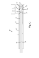
- FIG. 7 is an enlarged side view of select subcomponents of the EGR probe.
- FIG. 8 is an exploded side view of select subcompoents of the EGR probe.
- FIG. 12 is a schematic representation of an alternative embodiment of the EGR probe.
- the diagnostic system 10 may be used to measure CO 2 concentrations in essentially any application.
- the diagnostic system 10 is used to measure CO 2 concentrations within an engine intake manifold I to determine the spatial and temporal non-uniformities of CO 2 in the fluid stream.
- the system 10 may be used to measure cylinder-to-cylinder and cycle-to-cycle EGR fluctuations.
- the diagnostic system 10 may be used to quantify intake EGR fluctuations using CO 2 measurements.
- the present invention is described in connection with a diagnostic system 10 used with an intake manifold I for an internal combustion engine (not shown) having an exhaust gas recirculation (EGR) system (not shown).
- EGR exhaust gas recirculation
- the present invention can be used to assess spatial and temporal fluctuations in exhaust gas based on measurement of CO 2 concentration.
- the data collected by the diagnostic system 10 may be used to refine the EGR system, the intake manifold I, engine control parameters or other characteristics to improve performance of the engine and minimize NO X production.
- the present invention may be readily adapted for use in other types of diagnostics.
- the system 10 may allow diagnostics relating to other engine characteristics that can be assessed using CO 2 concentration.
- the diagnostic system 10 may also be used for applications that do not involve engines.
- the system may be modified to measure substances other than CO 2 .
- the light source, detector and processor may be modified to measure other substances, and provide diagnostics based on those substances can be performed.
- the inner end of the EGR probe 16 may be positioned so that the flow cells 28 and 32 (described below) are located at the location where samples are to be taken.
- the intake manifold apertures A are capable of receiving an EGR probe 16 manufactured in accordance with an embodiment of the present invention.
- the probe 16 is mounted to the intake manifold I via a standard bore-through SwageLok tube union boss, and positioned via a nonswaging ferrule.
- the EGR probe 16 may be mounted using other hardware, if desired.
- the EGR probe 16 may be installed in essentially any other structure containing a fluid stream, such as an exhaust manifold (not shown) or exhaust line (not shown).
- FIG. 1 is a schematic representation of diagnostic system 10 .
- the diagnostic system 10 of FIG. 1 generally includes a light source 12 , a pitch optical cable 14 , an EGR probe 16 with an internal sampling chamber 17 , a catch optical cable 18 , a detector 20 and a processor 22 for determining CO 2 concentration based on the output of the detector 20 .
- the EGR probe 16 of the illustrated embodiment is a single-port probe capable of being installed in a single opening, such as aperture A in intake manifold I (See FIGS. 9-11 ).
- the EGR probe 16 of this embodiment includes a tubular housing 50 having a circular cross-section that corresponds with the shape of the aperture A in the intake manifold I.
- the housing 50 defines an internal void configured to define the sampling chamber 17 and to house the probe optics.
- the sampling chamber 17 includes two separate flow cells (first flow cell 28 and second flow cell 32 ), and the probe optics are configured to direct the combined light beam through the flow cells.
- the probe optics of this embodiment include a pitch optical cable 24 , a window 26 , a lens 30 , a mirror 34 and a catch optical cable 36 .
- Pitch optical cable 14 and pitch optical cable 24 may be a single optical cable that extends from the light source 12 to the sampling chamber 17 , or they may be separate optical cables that are joined together to form a continuous light path.
- catch optical cable 18 and catch optical cable 36 may be a single optical cable that extends from the sampling chamber 17 to the detector 20 , or they may be separate optical cables that are joined together to form a continuous light path.
- the housing 50 may include an outer tube 60 , an inner tube 62 , a mount 64 , a first spacer 66 and a second spacer 68 .
- the outer tube 60 is approximately 3 ⁇ 8 of an inch in diameter and is configured to be fitted into a 3 ⁇ 8 of an inch diameter aperture A in the intake manifold I.
- the outer tube 60 is hollow and includes a closed inner end 72 . As perhaps best shown in FIG.
- the outer tube 60 defines sampling ports 90 and 92 that allow fluid from outside the EGR probe 16 to flow through the flow cells 28 and 32 .
- the mirror 34 , first spacer 66 , lens 30 , second spacer 68 , window 26 and mount 64 are stacked within the hollow outer tube 60 .
- the inner tube 62 may include an internal bore 70 configured to receive and support the pitch and catch optical cables.
- the inner tube 62 may be threadedly secured within the outer tube 60 to secure the various components of the EGR probe 16 .
- a nut 74 may be fitted around the outer tube 60 for securing the EGR probe 16 is an aperture A.
- the nut 74 may be a Swagelok nut.
- the EGR probe 16 may utilize a nonswaging ferrule to allow translation.
- the size, shape and configuration of EGR probe 16 is merely exemplary, and the EGR probe may vary from application to application.
- the size, cross-sectional shape and internal configuration of the housing 50 may vary depending on the application.
- the optical components may also vary depending on the application.
- EGR probe 16 ′ is shown in FIG. 12 .
- the EGR probe 16 ′ is generally identical to EGR probe 16 , except as described.
- EGR probe 16 ′ includes essentially the same optics as EGR prober 16 having pitch and catch optical cables 24 ′ and 36′, window 26 ′, first flow cell 28 ′, lens 30 ′, second flow cell 32 ′ and mirror 34 ′.
- the housing 50 ′ is somewhat different having a main tube 60 ′ and an end tube 62 ′ that are joined end to end and cooperatively form an internal void to contain the probe optics and supporting structures.
- the main tube 60 ′ and end tube 62 ′ may be welded together or other joined as desired.
- the housing 50 ′ includes a mount 64 ′ that is fitted into the main tube 60 ′ and the end tube 62 ′.
- the mount 64 ′ may be threaded or otherwise secure to main tube 60 ′ and/or the end tube 62 ′.
- the housing 50 ′ also includes a spacer 66 ′ that is fitted into the end tube 62 ′ where it is disposed between the mirror 34 ′ and the lens 30 ′.
- the EGR probe 16 is intended for use with a light source 12 that produces light in the mid-infrared (MIR) range.
- MIR mid-infrared
- the pitch optical cable 24 and the catch optical cable 36 may be hollow waveguides configured for use in conveying MIR light. Hollow waveguides may provide improved light transmission as compared to other types of optical fibers or light guides.
- the light source 12 is a combined light source that includes light produced by a signal source 40 and a reference source 42 .
- the EGR probe 16 is intended for use in measuring CO 2 concentration.
- the signal source 40 may be an MIR LED that produces light over a spectral range that is centered at 4.2 ⁇ m and overlaps the CO 2 absorption features near 4.3 ⁇ m.
- the characteristics of the signal source 40 may vary, for example, depending on the substance to be detected.
- the reference source 42 may be an MIR LED that produces light over a spectral range that is centered at 3.8 ⁇ m and does not coincide with CO 2 absorption features or other known interference species.
- the output of each light source 40 , 42 may be spectrally filtered as shown in FIGS. 2A and 2B to provide the desired light beam.
- FIG. 2A shows the spectral range R 1 of the filtered signal light source.
- FIG. 2B shows the spectral range R 2 of the filtered reference light source.
- the reference source 42 may be used by the processor 22 to normalize the measurements of the signal source 40 taken by the detector 20 .
- the spectrally-filtered output of the signal source 40 and the spectrally-filtered output of the reference source 42 are combined, for example, using a beam combiner 44 .
- the beam combiner 44 may be essentially any beam combiner or beam combiner/splitter capable of combining the light produced by the signal source 40 and the light produced by the reference source 42 into a composite light beam.
- the combined light beam is conveyed to the EGR probe 16 by pitch optical cable 14 and pitch optical cable 24 .
- the light is output from the pitch optical cable 24 through window 26 into first flow cell 28 . After passing through first flow cell 28 , the light passes through lens 30 and second flow cell 32 .
- the light then reflects off of mirror 34 and passes back through second flow cell 32 , lens 30 , first flow cell 28 and window 26 .
- the mirror 34 , lens 30 and window 26 are configured so that the returning light is directed into catch optical cable 36 .
- Catch optical cable 36 conveys the light to catch optical cable 18 .
- Catch optical cable 18 conveys the
- the signal and reference light sources are driven at different modulation frequencies, such as 50 kHz and 77 kHz. These particular modulation frequencies are merely exemplary and the modulation frequencies may vary from application to application. In practice, it is desirable for the modulation frequencies to be sufficiently distant from one another so that the signals can be adequately separated by the processor 22 .
- the signal light source 40 is operated by a signal driver 80 that modulates the signal light source 40 at 50 kHz
- the reference light source 42 is operated by a reference driver 82 that modulates the reference light source at 77 kHz.
- the drivers 80 and 82 may be enabled by the processor 22 , as shown in FIG. 1 .
- This configuration is merely exemplary and the light sources may be driven using other electronic controls.
- the processor 22 may be capable of directly driving the two light sources, 40 and 42 , at the desired modulation frequencies.
- the detector 20 may be essentially any photodetector capable of producing signals representative of the light beam returned from the EGR probe 16 .
- the output of the detector 20 is connected to processor 22 .
- the processor 22 may be essentially any processor capable of analyzing the detector output to provide CO 2 measurements.
- the light beam passed through the EGR probe 16 is a combined light beam that is a composite of the light produced by the signal source 40 and the reference source 42 .
- the processor 22 is configured to separate the combined light beam into a signal component and a reference component. In this embodiment, the signal component and reference component are resolved from the detector output using a Fourier transform.
- the processor 22 is also configured to normalize the signal component using the reference component.
- the EGR probe 16 may measure the CO 2 concentrations at various locations within the intake manifold to determine the spatial uniformity of exhaust gas recirculation.
- the present invention may use a single EGR probe 16 that may be moved from time to time to measure CO 2 concentrations at different locations.
- the EGR probe 16 may be used to measure the CO 2 concentrations at each cylinder to assess the cylinder-to-cylinder uniformity of recirculated exhaust gas.
- the system 10 may include a plurality of EGR probes 16 that allow simultaneous measurements from different locations within the manifold. In some application, a separate diagnostic system may be used for each location, and the output of the different systems may be compared to assess the differences.
- the EGR probe 16 may measure the CO 2 concentrations at a given location over time to determine changes in CO 2 concentration over time. In this application, the temporal differences may be determined to assess cycle-to-cycle uniformity of the EGR system.
- a single EGR probe 16 may be used to measure CO 2 concentrations at a single location over time, or a plurality of EGR probes may be used to simultaneously measure CO 2 concentrations at different locations.
- the present invention may be used to take measurements at essentially any timescale (e.g. individual valve events, or intra-valve events, or longer term drift or variations).
- the diagnostic system 10 may be used to perform other types of diagnostics that depend on CO 2 concentration or the concentration of other substances that may be measured using the present invention.
- the signal and reference light beams are combined into a single light beam using a beam combiner/splitter.
- the beam combiner may be essentially any beam combiner or beam splitter capable of combining the MIR output of the signal and reference light sources into a single composite light beam.
- the method may also include the steps of (a) installing the EGR probe 16 in a first location in the intake manifold I, (b) taking CO 2 measurements at the first location, (c) installing the EGR probe 16 in a second location, (d) taking CO 2 measurements at the second location and (e) repeating these steps for each additional location to be measured.
- the location may be varied by moving the EGR probe 16 from one aperture A to another and/or by varying the depth of EGR rpobe 16 within an aperture A.
- FIG. 11 is a schematic representation of the EGR probe 16 in the intake manifold I. The depth of the EGR probe 16 within the intake manifold I can be adjusted to essentially any location along line L.
- the measurements produced by the detector 20 are processed by processor 22 to determine the concentration of CO 2 .
- This process may include the steps of: (a) separating the detector measurements into a signal component and a reference component; (b) normalizing the signal component using the reference component and (c) determining the CO 2 concentration from the normalized signal component.
- the step of separating the detector measurements into a signal component and a reference component may include processing the measurements using a Fourier transform that separates the components based on their different modulation frequencies. Such processing also minimizes the effect of detector noise on the measurement precision.
- the step of normalizing the signal component may include adjusting the signal component as a function of the reference component. Once the signal component has been normalized, the CO 2 concentration may be determined using conventional absorption spectroscopy methodologies, which will not be described in detail here.
Abstract
Description
Claims (16)
Priority Applications (2)
| Application Number | Priority Date | Filing Date | Title |
|---|---|---|---|
| US13/912,462 US9000374B2 (en) | 2012-06-08 | 2013-06-07 | EGR distribution and fluctuation probe based on CO2 measurements |
| US14/051,788 US9068933B2 (en) | 2012-06-08 | 2013-10-11 | EGR distribution and fluctuation probe based on CO2 measurements |
Applications Claiming Priority (2)
| Application Number | Priority Date | Filing Date | Title |
|---|---|---|---|
| US201261657205P | 2012-06-08 | 2012-06-08 | |
| US13/912,462 US9000374B2 (en) | 2012-06-08 | 2013-06-07 | EGR distribution and fluctuation probe based on CO2 measurements |
Related Child Applications (1)
| Application Number | Title | Priority Date | Filing Date |
|---|---|---|---|
| US14/051,788 Continuation-In-Part US9068933B2 (en) | 2012-06-08 | 2013-10-11 | EGR distribution and fluctuation probe based on CO2 measurements |
Publications (2)
| Publication Number | Publication Date |
|---|---|
| US20130327943A1 US20130327943A1 (en) | 2013-12-12 |
| US9000374B2 true US9000374B2 (en) | 2015-04-07 |
Family
ID=49714519
Family Applications (1)
| Application Number | Title | Priority Date | Filing Date |
|---|---|---|---|
| US13/912,462 Active 2033-08-22 US9000374B2 (en) | 2012-06-08 | 2013-06-07 | EGR distribution and fluctuation probe based on CO2 measurements |
Country Status (1)
| Country | Link |
|---|---|
| US (1) | US9000374B2 (en) |
Cited By (3)
| Publication number | Priority date | Publication date | Assignee | Title |
|---|---|---|---|---|
| US9541498B1 (en) | 2015-08-21 | 2017-01-10 | Ut-Battelle, Llc | Diagnostic system for measuring temperature, pressure, CO2 concentration and H2O concentration in a fluid stream |
| US20170234707A1 (en) * | 2016-02-12 | 2017-08-17 | Leo BRETON | Real-Time Fluid Species Mass Flowmeter |
| WO2018178306A1 (en) * | 2017-03-31 | 2018-10-04 | Siemens Aktiengesellschaft | Gas analyser |
Families Citing this family (9)
| Publication number | Priority date | Publication date | Assignee | Title |
|---|---|---|---|---|
| US20150029693A1 (en) * | 2013-07-23 | 2015-01-29 | Delphi Technologies, Inc. | Vehicle instrument panel with light source diagnostics |
| JP6317277B2 (en) * | 2015-02-18 | 2018-04-25 | トヨタ自動車株式会社 | Fuel gas concentration measuring device for internal combustion engine |
| CN104794870B (en) * | 2015-04-22 | 2017-05-03 | 国家电网公司 | Electric power optical cable maintenance pre-warning system and method |
| JP6480255B2 (en) * | 2015-05-14 | 2019-03-06 | 株式会社Soken | Fuel concentration measuring device |
| EP3539108B1 (en) * | 2016-11-11 | 2020-08-12 | Carrier Corporation | High sensitivity fiber optic based detection |
| CA3043583A1 (en) | 2016-11-11 | 2018-05-17 | Carrier Corporation | High sensitivity fiber optic based detection |
| WO2018089654A1 (en) | 2016-11-11 | 2018-05-17 | Carrier Corporation | High sensitivity fiber optic based detection |
| EP3539105A1 (en) | 2016-11-11 | 2019-09-18 | Carrier Corporation | High sensitivity fiber optic based detection |
| EP3539109B8 (en) | 2016-11-11 | 2024-02-14 | Carrier Corporation | High sensitivity fiber optic based detection |
Citations (8)
| Publication number | Priority date | Publication date | Assignee | Title |
|---|---|---|---|---|
| US5373367A (en) | 1992-10-21 | 1994-12-13 | Qualimetrics, Inc. | Multiple angle and redundant visibility sensor |
| US5751423A (en) | 1996-12-06 | 1998-05-12 | United Sciences, Inc. | Opacity and forward scattering monitor using beam-steered solid-state light source |
| US5831730A (en) | 1996-12-06 | 1998-11-03 | United Sciences, Inc. | Method for monitoring particulates using beam-steered solid-state light source |
| US6744059B2 (en) | 2001-08-21 | 2004-06-01 | Spx Corporation | Optical path structure for open path emissions sensing with spinning mirror |
| US20040263851A1 (en) * | 2003-06-26 | 2004-12-30 | Dobbs Michael E. | Active remote sensing using a simultaneous spectral sampling technique |
| US7301641B1 (en) | 2004-04-16 | 2007-11-27 | United States Of America As Represented By The Secretary Of The Navy | Fiber optic smoke detector |
| US7839492B2 (en) | 2008-06-12 | 2010-11-23 | Ut-Battelle, Llc | Laser-induced fluorescence fiber optic probe measurement of oil dilution by fuel |
| US7884937B2 (en) * | 2007-04-19 | 2011-02-08 | Science & Engineering Services, Inc. | Airborne tunable mid-IR laser gas-correlation sensor |
-
2013
- 2013-06-07 US US13/912,462 patent/US9000374B2/en active Active
Patent Citations (11)
| Publication number | Priority date | Publication date | Assignee | Title |
|---|---|---|---|---|
| US5373367A (en) | 1992-10-21 | 1994-12-13 | Qualimetrics, Inc. | Multiple angle and redundant visibility sensor |
| US5751423A (en) | 1996-12-06 | 1998-05-12 | United Sciences, Inc. | Opacity and forward scattering monitor using beam-steered solid-state light source |
| US5831730A (en) | 1996-12-06 | 1998-11-03 | United Sciences, Inc. | Method for monitoring particulates using beam-steered solid-state light source |
| US5999257A (en) | 1996-12-06 | 1999-12-07 | United Sciences, Inc. | Method and apparatus for monitoring particulates using back-scattered laser with steerable detection optics |
| US6744059B2 (en) | 2001-08-21 | 2004-06-01 | Spx Corporation | Optical path structure for open path emissions sensing with spinning mirror |
| US6744516B2 (en) | 2001-08-21 | 2004-06-01 | Spx Corporation | Optical path structure for open path emissions sensing |
| US6833922B2 (en) | 2001-08-21 | 2004-12-21 | Spx Corporation | Optical path structure for open path emissions sensing with opposed sources |
| US20040263851A1 (en) * | 2003-06-26 | 2004-12-30 | Dobbs Michael E. | Active remote sensing using a simultaneous spectral sampling technique |
| US7301641B1 (en) | 2004-04-16 | 2007-11-27 | United States Of America As Represented By The Secretary Of The Navy | Fiber optic smoke detector |
| US7884937B2 (en) * | 2007-04-19 | 2011-02-08 | Science & Engineering Services, Inc. | Airborne tunable mid-IR laser gas-correlation sensor |
| US7839492B2 (en) | 2008-06-12 | 2010-11-23 | Ut-Battelle, Llc | Laser-induced fluorescence fiber optic probe measurement of oil dilution by fuel |
Non-Patent Citations (2)
| Title |
|---|
| C. Schulz, Advanced Laser Imaging Diagnostics in Combustion, Z. Phys. Chem. 219 (2005) pp. 509-554. |
| Michael Cundy, Torsten Schucht, Olaf Thiele, and Volker Sick, High-speed laser-induced fluorescence and spark plug absorption sensor diagnostics for mixing and combustion studies in engines, Applied Optics, vol. 48, No. 4 / Feb. 1, 2009. |
Cited By (6)
| Publication number | Priority date | Publication date | Assignee | Title |
|---|---|---|---|---|
| US9541498B1 (en) | 2015-08-21 | 2017-01-10 | Ut-Battelle, Llc | Diagnostic system for measuring temperature, pressure, CO2 concentration and H2O concentration in a fluid stream |
| US9851296B2 (en) | 2015-08-21 | 2017-12-26 | Ut-Battelle, Llc | Diagnostic system for measuring temperature, pressure, CO2 concentration and H2O concentration in a fluid stream |
| US20170234707A1 (en) * | 2016-02-12 | 2017-08-17 | Leo BRETON | Real-Time Fluid Species Mass Flowmeter |
| US10578468B2 (en) * | 2016-02-12 | 2020-03-03 | Leo BRETON | Real-time fluid species mass flowmeter |
| WO2018178306A1 (en) * | 2017-03-31 | 2018-10-04 | Siemens Aktiengesellschaft | Gas analyser |
| US11060969B2 (en) | 2017-03-31 | 2021-07-13 | Siemens Aktiengesellschaft | Gas analyzer |
Also Published As
| Publication number | Publication date |
|---|---|
| US20130327943A1 (en) | 2013-12-12 |
Similar Documents
| Publication | Publication Date | Title |
|---|---|---|
| US9000374B2 (en) | EGR distribution and fluctuation probe based on CO2 measurements | |
| US9068933B2 (en) | EGR distribution and fluctuation probe based on CO2 measurements | |
| US7839492B2 (en) | Laser-induced fluorescence fiber optic probe measurement of oil dilution by fuel | |
| Schindler et al. | A photoacoustic sensor system for time resolved quantification of diesel soot emissions | |
| CN101535797B (en) | Reaction analyzer, recording medium, measurement system, and control system | |
| CN106802288B (en) | Gas-detecting device and method based on tunable laser and super continuous spectrums laser | |
| CN103278472B (en) | A kind of Fourier infrared spectrograph and sample gas absorption cell | |
| Weikl et al. | Simultaneous temperature and exhaust-gas recirculation-measurements in a homogeneous charge-compression ignition engine by use of pure rotational coherent anti-Stokes Raman spectroscopy | |
| CN206399819U (en) | Automobile exhaust detection system | |
| US5475223A (en) | System for monitoring exhaust gas composition | |
| Barro et al. | Optical investigations of soot reduction mechanisms using post-injections in a cylindrical constant volume chamber (CCVC) | |
| CN104777145A (en) | Raman spectrum system aiming at industrial gas multi-component analysis | |
| Wermuth et al. | Absorption and fluorescence data of acetone, 3-pentanone, biacetyl, and toluene at engine-specific combinations of temperature and pressure | |
| US9851296B2 (en) | Diagnostic system for measuring temperature, pressure, CO2 concentration and H2O concentration in a fluid stream | |
| JP2011241753A (en) | Device for monitoring condition in cylinder of spark ignition type internal combustion engine and controller | |
| Niklas et al. | Quantitative measurement of combustion gases in harsh environments using NDIR spectroscopy | |
| Zhang et al. | Fast hybrid sensor for soot of production CI engines | |
| Parks et al. | Rapid in situ measurement of fuel dilution of oil in a diesel engine using laser-induced fluorescence spectroscopy | |
| Zhang et al. | Fast measurement of soot by in-situ LII on a production engine | |
| US10288561B1 (en) | Gas analyzer | |
| CN209182227U (en) | Atmospheric analysis detection system based on DOAS and LIBS technology | |
| Bauke et al. | Quantitative, time-resolved detection of CH 4 concentrations in flows for injection analysis in CNG engines using IR absorption | |
| Wagner et al. | Portable and Compact TDLAS Measurement System for Exhaust Gas Diagnostics at Real Driving Conditions | |
| Wagner et al. | Exhaust Gas Diagnostics at Real Driving Conditions using a Compact TDLAS Measurement System | |
| Yeo | Development and application of in-cylinder fuel concentration and pyrometry optical diagnostic tools in diesel-ignited dual-fuel natural gas engines |
Legal Events
| Date | Code | Title | Description |
|---|---|---|---|
| AS | Assignment |
Owner name: UT-BATTELLE, LLC, TENNESSEE Free format text: ASSIGNMENT OF ASSIGNORS INTEREST;ASSIGNOR:OAK RIDGE ASSOCIATED UNIVERSITIES;REEL/FRAME:030813/0172 Effective date: 20130712 Owner name: OAK RIDGE ASSOCIATED UNIVERSITIES, TENNESSEE Free format text: ASSIGNMENT OF ASSIGNORS INTEREST;ASSIGNOR:YOO, JI HYUNG;REEL/FRAME:030813/0155 Effective date: 20130702 Owner name: UT-BATTELLE, LLC, TENNESSEE Free format text: ASSIGNMENT OF ASSIGNORS INTEREST;ASSIGNORS:PARTRIDGE, WILLIAM P.;PARKS, JAMES E., II;REEL/FRAME:030813/0313 Effective date: 20130702 |
|
| AS | Assignment |
Owner name: U.S. DEPARTMENT OF ENERGY, DISTRICT OF COLUMBIA Free format text: CONFIRMATORY LICENSE;ASSIGNOR:UT-BATTELLE, LLC;REEL/FRAME:033838/0273 Effective date: 20140724 |
|
| STCF | Information on status: patent grant |
Free format text: PATENTED CASE |
|
| MAFP | Maintenance fee payment |
Free format text: PAYMENT OF MAINTENANCE FEE, 4TH YEAR, LARGE ENTITY (ORIGINAL EVENT CODE: M1551); ENTITY STATUS OF PATENT OWNER: LARGE ENTITY Year of fee payment: 4 |
|
| MAFP | Maintenance fee payment |
Free format text: PAYMENT OF MAINTENANCE FEE, 8TH YEAR, LARGE ENTITY (ORIGINAL EVENT CODE: M1552); ENTITY STATUS OF PATENT OWNER: LARGE ENTITY Year of fee payment: 8 |