US8998469B1 - Lighted ceramic tile assembly - Google Patents
Lighted ceramic tile assembly Download PDFInfo
- Publication number
- US8998469B1 US8998469B1 US13/736,422 US201313736422A US8998469B1 US 8998469 B1 US8998469 B1 US 8998469B1 US 201313736422 A US201313736422 A US 201313736422A US 8998469 B1 US8998469 B1 US 8998469B1
- Authority
- US
- United States
- Prior art keywords
- panel
- extending
- trunk line
- coupled
- chamber
- Prior art date
- Legal status (The legal status is an assumption and is not a legal conclusion. Google has not performed a legal analysis and makes no representation as to the accuracy of the status listed.)
- Expired - Fee Related, expires
Links
Images


Classifications
-
- F—MECHANICAL ENGINEERING; LIGHTING; HEATING; WEAPONS; BLASTING
- F21—LIGHTING
- F21V—FUNCTIONAL FEATURES OR DETAILS OF LIGHTING DEVICES OR SYSTEMS THEREOF; STRUCTURAL COMBINATIONS OF LIGHTING DEVICES WITH OTHER ARTICLES, NOT OTHERWISE PROVIDED FOR
- F21V33/00—Structural combinations of lighting devices with other articles, not otherwise provided for
- F21V33/006—General building constructions or finishing work for buildings, e.g. roofs, gutters, stairs or floors; Garden equipment; Sunshades or parasols
-
- G—PHYSICS
- G02—OPTICS
- G02B—OPTICAL ELEMENTS, SYSTEMS OR APPARATUS
- G02B6/00—Light guides; Structural details of arrangements comprising light guides and other optical elements, e.g. couplings
- G02B6/0001—Light guides; Structural details of arrangements comprising light guides and other optical elements, e.g. couplings specially adapted for lighting devices or systems
- G02B6/0005—Light guides; Structural details of arrangements comprising light guides and other optical elements, e.g. couplings specially adapted for lighting devices or systems the light guides being of the fibre type
- G02B6/0006—Coupling light into the fibre
-
- G—PHYSICS
- G02—OPTICS
- G02B—OPTICAL ELEMENTS, SYSTEMS OR APPARATUS
- G02B6/00—Light guides; Structural details of arrangements comprising light guides and other optical elements, e.g. couplings
- G02B6/0001—Light guides; Structural details of arrangements comprising light guides and other optical elements, e.g. couplings specially adapted for lighting devices or systems
- G02B6/0005—Light guides; Structural details of arrangements comprising light guides and other optical elements, e.g. couplings specially adapted for lighting devices or systems the light guides being of the fibre type
- G02B6/0008—Light guides; Structural details of arrangements comprising light guides and other optical elements, e.g. couplings specially adapted for lighting devices or systems the light guides being of the fibre type the light being emitted at the end of the fibre
Definitions
- the disclosure relates to tile devices and more particularly pertains to a new tile device for selectively illuminating tiles to enhance visibility of a floor or wall surface while enhancing the decorative appearance of the floor or wall surface.
- An embodiment of the disclosure meets the needs presented above by generally comprising a panel having an upper surface, a lower surface, and a perimeter edge extending around the panel between the upper surface and the lower surface.
- a primary conduit is coupled to the panel.
- Each of a plurality of secondary conduits has a first end extending into the primary conduit and a second end extending through the upper surface.
- a fiber optic trunk line is coupled to the panel and positioned in the primary conduit.
- Each of a plurality of fiber optic filaments is positioned in and extends through an associated one of the secondary conduits.
- Each filament has a second end positioned proximate the second end of the associated secondary conduit and a first end operationally coupled to the trunk line. Thus, the second end of the filament provides visible light through the second end of the associated secondary conduit.
- FIG. 1 is a partial cutaway top front side perspective view of a lighted ceramic tile assembly according to an embodiment of the disclosure.
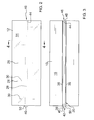
- FIG. 2 is a top view of an embodiment of the disclosure.
- FIG. 3 is a bottom view of an embodiment of the disclosure.
- FIG. 4 is a cross-sectional view of an embodiment of the disclosure taken along line 4 - 4 of FIG. 2 .
- FIG. 5 is a top view of an embodiment of the disclosure.
- FIG. 6 is a top front side perspective view of an embodiment of the disclosure.
- FIGS. 1 through 6 With reference now to the drawings, and in particular to FIGS. 1 through 6 thereof, a new tile device embodying the principles and concepts of an embodiment of the disclosure and generally designated by the reference numeral 10 will be described.
- the lighted ceramic tile assembly 10 generally comprises a plurality of interconnecting panels 12 .
- Each panel 12 has an upper surface 14 , a lower surface 16 , and a perimeter edge 18 extending around the panel 12 between the upper surface 14 and the lower surface 16 .
- Each panel 12 has a primary conduit 20 coupled to the panel 12 .
- Each panel 12 has a plurality of secondary conduits 22 .
- the secondary conduits 22 extend through the panel 12 .
- Each secondary conduit 22 has a first end 24 extending into the primary conduit 20 of the panel 12 .
- Each secondary conduit 22 has a second end 26 extending through the upper surface 14 of the panel 12 .
- a plurality of fiber optic trunk lines 28 is provided.
- Each trunk line 28 is coupled to an associated one of the panels 12 and positioned in the primary conduit 20 of the associated panel 12 .
- a plurality of fiber optic filaments 30 is provided. Each filament 30 is positioned in and extends through an associated one of the secondary conduits 22 . Each filament 30 has a second end 32 positioned proximate the second end 26 of the associated secondary conduit 22 . Each filament 30 further has a first end 34 operationally coupled to the trunk line 28 of the associated panel 12 . Thus, the second end 32 of the filament 30 provides visible light through the second end 26 of the associated secondary conduit 22 .
- Each panel 12 having a pair of elongated projections 36 coupled to and extending from the lower surface 16 of the panel 12 .
- the projections 36 define the primary conduit 20 of the panel 12 .
- An arcuate upper surface 38 extends between the projections 36 of each panel 12 .
- the trunk line 28 of the associated panel 12 abuts the arcuate upper surface 38 of the panel 12 .
- Each trunk line 28 has a first end 40 extending outwardly from the perimeter edge 18 of the associated panel 12 defining a male connector 42 for the associated panel 12 .
- Each trunk line 28 further has a second end 44 inset from the perimeter edge 18 of the associated panel 12 defining a female connector 46 of the associated panel 12 .
- the male connector 42 of each panel 12 is couplable to the female connector 46 of an adjacently positioned one of the panels 12 .
- the panels 12 can be coupled together in series.
- a cavity 48 extends into the perimeter edge 18 of the panel 12 adjacent to the second end 44 of the trunk line 28 .
- the cavity 48 extends radially outward from the primary conduit 20 and may be annular further defining an outer portion of the female connector 46 .
- a collar 50 may be coupled to the trunk line 28 .
- the collar 50 extends radially outward from the trunk line 28 adjacent to the first end 40 of the trunk line 28 such that the collar 50 is incorporated into the male connector 42 .
- the male connector 42 and female connector 46 may be configured to provide a desired spacing between the adjacent panels 12 .
- the spacing may be between 1 and 7 millimeters to accommodate grouting between the panels 12 .
- the spacing may be standardized when the male connector 42 is fully inserted into the female connector 46 to provide a consistent spacing between the panels 12 .
- An electrical box 54 has a first chamber 56 and a second chamber 58 .
- a first aperture 60 extends into the first chamber 56 wherein the electrical box 54 is configured for coupling to electrical wiring 62 extending into the first chamber 56 .
- a light emitter 66 is coupled to the electrical box 54 .
- the light emitter 66 is positioned in the second chamber 58 and has electrical connections 68 extending into the first chamber 56 .
- the light emitter 66 is configured for being electrically coupled to the wiring 62 extending into the first chamber 54 .
- a second aperture 70 extends through the electrical box 54 into the second chamber 58 .
- a trunk connector 72 is coupled to the electrical box 54 .
- the trunk connector 72 is adjacent the second aperture 70 and may be a cone shape to facilitate collection of light from said light emitter into said trunk lines 28 .
- Each trunk line 28 is operationally coupled to the trunk connector 72 wherein the light emitter 66 provides light to each trunk line 28 when the light emitter 66 is illuminated.
- a channel 76 is extended into a base member 78 such as drywall.
- the panels 12 are interconnected by inserting the male connectors 42 into associated female connectors 46 and installing the panels 12 on the base member 78 .
- the trunk lines 28 are provided with light from the light emitter 66 .
- the second ends 26 of the secondary conduits 22 are arranged into a desired pattern to provide decorations to the panels 12 .
Abstract
A lighted tile assembly illuminates tiles to enhance visibility of a floor or wall surface while enhancing the decorative appearance of the floor surface. The assembly includes a panel having a perimeter edge extending between an upper surface and a lower surface. Each of a plurality of secondary conduits has a first end extending into a primary conduit and a second end extending through the upper surface. A fiber optic trunk line is coupled to the panel and positioned in the primary conduit. Each of a plurality of fiber optic filaments is positioned in and extends through an associated one of the secondary conduits. Each filament has a second end positioned proximate the second end of the associated secondary conduit and a first end operationally coupled to the trunk line. Thus, the second end of the filament provides visible light through the second end of the associated secondary conduit.
Description
The disclosure relates to tile devices and more particularly pertains to a new tile device for selectively illuminating tiles to enhance visibility of a floor or wall surface while enhancing the decorative appearance of the floor or wall surface.
An embodiment of the disclosure meets the needs presented above by generally comprising a panel having an upper surface, a lower surface, and a perimeter edge extending around the panel between the upper surface and the lower surface. A primary conduit is coupled to the panel. Each of a plurality of secondary conduits has a first end extending into the primary conduit and a second end extending through the upper surface. A fiber optic trunk line is coupled to the panel and positioned in the primary conduit. Each of a plurality of fiber optic filaments is positioned in and extends through an associated one of the secondary conduits. Each filament has a second end positioned proximate the second end of the associated secondary conduit and a first end operationally coupled to the trunk line. Thus, the second end of the filament provides visible light through the second end of the associated secondary conduit.
There has thus been outlined, rather broadly, the more important features of the disclosure in order that the detailed description thereof that follows may be better understood, and in order that the present contribution to the art may be better appreciated. There are additional features of the disclosure that will be described hereinafter and which will form the subject matter of the claims appended hereto.
The objects of the disclosure, along with the various features of novelty which characterize the disclosure, are pointed out with particularity in the claims annexed to and forming a part of this disclosure.
The disclosure will be better understood and objects other than those set forth above will become apparent when consideration is given to the following detailed description thereof. Such description makes reference to the annexed drawings wherein:
With reference now to the drawings, and in particular to FIGS. 1 through 6 thereof, a new tile device embodying the principles and concepts of an embodiment of the disclosure and generally designated by the reference numeral 10 will be described.
As best illustrated in FIGS. 1 through 6 , the lighted ceramic tile assembly 10 generally comprises a plurality of interconnecting panels 12. Each panel 12 has an upper surface 14, a lower surface 16, and a perimeter edge 18 extending around the panel 12 between the upper surface 14 and the lower surface 16. Each panel 12 has a primary conduit 20 coupled to the panel 12. Each panel 12 has a plurality of secondary conduits 22. The secondary conduits 22 extend through the panel 12. Each secondary conduit 22 has a first end 24 extending into the primary conduit 20 of the panel 12. Each secondary conduit 22 has a second end 26 extending through the upper surface 14 of the panel 12. A plurality of fiber optic trunk lines 28 is provided. Each trunk line 28 is coupled to an associated one of the panels 12 and positioned in the primary conduit 20 of the associated panel 12. A plurality of fiber optic filaments 30 is provided. Each filament 30 is positioned in and extends through an associated one of the secondary conduits 22. Each filament 30 has a second end 32 positioned proximate the second end 26 of the associated secondary conduit 22. Each filament 30 further has a first end 34 operationally coupled to the trunk line 28 of the associated panel 12. Thus, the second end 32 of the filament 30 provides visible light through the second end 26 of the associated secondary conduit 22.
Each panel 12 having a pair of elongated projections 36 coupled to and extending from the lower surface 16 of the panel 12. The projections 36 define the primary conduit 20 of the panel 12. An arcuate upper surface 38 extends between the projections 36 of each panel 12. The trunk line 28 of the associated panel 12 abuts the arcuate upper surface 38 of the panel 12.
Each trunk line 28 has a first end 40 extending outwardly from the perimeter edge 18 of the associated panel 12 defining a male connector 42 for the associated panel 12. Each trunk line 28 further has a second end 44 inset from the perimeter edge 18 of the associated panel 12 defining a female connector 46 of the associated panel 12. The male connector 42 of each panel 12 is couplable to the female connector 46 of an adjacently positioned one of the panels 12. Thus, the panels 12 can be coupled together in series. A cavity 48 extends into the perimeter edge 18 of the panel 12 adjacent to the second end 44 of the trunk line 28. The cavity 48 extends radially outward from the primary conduit 20 and may be annular further defining an outer portion of the female connector 46. A collar 50 may be coupled to the trunk line 28. The collar 50 extends radially outward from the trunk line 28 adjacent to the first end 40 of the trunk line 28 such that the collar 50 is incorporated into the male connector 42. When coupled together, adjacent panels 12 the male connector 42 and female connector 46 may be configured to provide a desired spacing between the adjacent panels 12. The spacing may be between 1 and 7 millimeters to accommodate grouting between the panels 12. The spacing may be standardized when the male connector 42 is fully inserted into the female connector 46 to provide a consistent spacing between the panels 12.
An electrical box 54 has a first chamber 56 and a second chamber 58. A first aperture 60 extends into the first chamber 56 wherein the electrical box 54 is configured for coupling to electrical wiring 62 extending into the first chamber 56. A light emitter 66 is coupled to the electrical box 54. The light emitter 66 is positioned in the second chamber 58 and has electrical connections 68 extending into the first chamber 56. Thus, the light emitter 66 is configured for being electrically coupled to the wiring 62 extending into the first chamber 54. A second aperture 70 extends through the electrical box 54 into the second chamber 58. A trunk connector 72 is coupled to the electrical box 54. The trunk connector 72 is adjacent the second aperture 70 and may be a cone shape to facilitate collection of light from said light emitter into said trunk lines 28. Each trunk line 28 is operationally coupled to the trunk connector 72 wherein the light emitter 66 provides light to each trunk line 28 when the light emitter 66 is illuminated.
In use, a channel 76 is extended into a base member 78 such as drywall. The panels 12 are interconnected by inserting the male connectors 42 into associated female connectors 46 and installing the panels 12 on the base member 78. The trunk lines 28 are provided with light from the light emitter 66. The second ends 26 of the secondary conduits 22 are arranged into a desired pattern to provide decorations to the panels 12.
With respect to the above description then, it is to be realized that the optimum dimensional relationships for the parts of an embodiment enabled by the disclosure, to include variations in size, materials, shape, form, function and manner of operation, assembly and use, are deemed readily apparent and obvious to one skilled in the art, and all equivalent relationships to those illustrated in the drawings and described in the specification are intended to be encompassed by an embodiment of the disclosure.
Therefore, the foregoing is considered as illustrative only of the principles of the disclosure. Further, since numerous modifications and changes will readily occur to those skilled in the art, it is not desired to limit the disclosure to the exact construction and operation shown and described, and accordingly, all suitable modifications and equivalents may be resorted to, falling within the scope of the disclosure.
Claims (5)
1. A lighted tile assembly comprising:
a panel having an upper surface, a lower surface, and a perimeter edge extending around said panel between said upper surface and said lower surface;
a primary conduit coupled to said panel;
a plurality of secondary conduits, each secondary conduit having a first end extending into said primary conduit, each secondary conduit having a second end extending through said upper surface;
a fiber optic trunk line coupled to said panel and positioned in said primary conduit; and
a plurality of fiber optic filaments, each filament being positioned in and extending through an associated one of said secondary conduits, each filament having a second end positioned proximate said second end of said associated secondary conduit, each said filament having a first end operationally coupled to said trunk line wherein said second end of said filament provides visible light through said second end of said associated secondary conduit;
a pair of elongated projections coupled to and extending from said lower surface of said panel, said projections defining said primary conduit;
an arcuate upper surface extending between said projections, said trunk line abutting said arcuate upper surface; and
said trunk line having a first end extending outwardly from said perimeter edge of said panel defining a male connector, said trunk line having a second end inset from said perimeter edge of said panel defining a female connector.
2. The assembly of claim 1 , further comprising a plurality of said panels, said male connector of each said panel being couplable to said female connector of an adjacently positioned one of said panels.
3. The assembly of claim 1 , further comprising:
a cavity extending into said perimeter edge of said panel adjacent to said second end of said trunk line, said cavity extending radially outward from said primary conduit; and
a collar coupled to said trunk line, said collar extending radially outward from said trunk line adjacent to said first end of said trunk line.
4. A lighted tile assembly comprising:
a panel having an upper surface, a lower surface, and a perimeter edge extending around said panel between said upper surface and said lower surface;
a primary conduit coupled to said panel;
a plurality of secondary conduits, each secondary conduit having a first end extending into said primary conduit, each secondary conduit having a second end extending through said upper surface;
a fiber optic trunk line coupled to said panel and positioned in said primary conduit; and
a plurality of fiber optic filaments, each filament being positioned in and extending through an associated one of said secondary conduits, each filament having a second end positioned proximate said second end of said associated secondary conduit, each said filament having a first end operationally coupled to said trunk line wherein said second end of said filament provides visible light through said second end of said associated secondary conduit;
an electrical box having a first chamber and a second chamber;
a first aperture extending into said first chamber wherein said electrical box is configured for coupling to electrical wiring extending into said first chamber;
a light emitter coupled to said electrical box, said light emitter being positioned in said second chamber, said light emitter having electrical connections extending into said first chamber wherein said light emitter is configured for being electrically coupled to the wiring extending into said first chamber;
a second aperture extending through said electrical box into said second chamber; and
a trunk connector coupled to said electrical box, said trunk connector being adjacent said second aperture, said trunk line being coupled to said trunk connector wherein said light emitter provides light to said trunk line when said light emitter is illuminated.
5. A lighted tile assembly comprising:
a plurality of panels, each said panel having an upper surface, a lower surface, and a perimeter edge extending around said panel between said upper surface and said lower surface;
each said panel having a primary conduit coupled to said panel;
each said panel having a plurality of secondary conduits, said secondary conduits extending through said panel, each secondary conduit having a first end extending into said primary conduit of said panel, each secondary conduit having a second end extending through said upper surface of said panel;
a plurality of fiber optic trunk lines, each trunk line being coupled to an associated one of said panels and positioned in said primary conduit of said associated panel;
a plurality of fiber optic filaments, each filament being positioned in and extending through an associated one of said secondary conduits, each filament having a second end positioned proximate said second end of said associated secondary conduit, each said filament having a first end operationally coupled to said trunk line of said associated panel wherein said second end of said filament provides visible light through said second end of said associated secondary conduit;
each said panel having a pair of elongated projections coupled to and extending from said lower surface of said panel, said projections defining said primary conduit of said panel, an arcuate upper surface extending between said projections of each said panel, said trunk line of said associated panel abutting said arcuate upper surface of said panel;
each said trunk line having a first end extending outwardly from said perimeter edge of said associated panel defining a male connector for said associated panel, each said trunk line having a second end inset from said perimeter edge of said associated panel defining a female connector of said associated panel, said male connector of each said panel being couplable to said female connector of an adjacently positioned one of said panels;
a cavity extending into said perimeter edge of said panel adjacent to said second end of said trunk line, said cavity extending radially outward from said primary conduit;
a collar coupled to said trunk line, said collar extending radially outward from said trunk line adjacent to said first end of said trunk line;
an electrical box having a first chamber and a second chamber;
a first aperture extending into said first chamber wherein said electrical box is configured for coupling to electrical wiring extending into said first chamber;
a light emitter coupled to said electrical box, said light emitter being positioned in said second chamber, said light emitter having electrical connections extending into said first chamber wherein said light emitter is configured for being electrically coupled to the wiring extending into said first chamber;
a second aperture extending through said electrical box into said second chamber; and
a trunk connector coupled to said electrical box, said trunk connector being adjacent said second aperture, each said trunk line being operationally coupled to said trunk connector wherein said light emitter provides light to each said trunk line when said light emitter is illuminated.
Priority Applications (1)
| Application Number | Priority Date | Filing Date | Title |
|---|---|---|---|
| US13/736,422 US8998469B1 (en) | 2013-01-08 | 2013-01-08 | Lighted ceramic tile assembly |
Applications Claiming Priority (1)
| Application Number | Priority Date | Filing Date | Title |
|---|---|---|---|
| US13/736,422 US8998469B1 (en) | 2013-01-08 | 2013-01-08 | Lighted ceramic tile assembly |
Publications (1)
| Publication Number | Publication Date |
|---|---|
| US8998469B1 true US8998469B1 (en) | 2015-04-07 |
Family
ID=52745028
Family Applications (1)
| Application Number | Title | Priority Date | Filing Date |
|---|---|---|---|
| US13/736,422 Expired - Fee Related US8998469B1 (en) | 2013-01-08 | 2013-01-08 | Lighted ceramic tile assembly |
Country Status (1)
| Country | Link |
|---|---|
| US (1) | US8998469B1 (en) |
Cited By (2)
| Publication number | Priority date | Publication date | Assignee | Title |
|---|---|---|---|---|
| US20150260823A1 (en) * | 2014-03-11 | 2015-09-17 | Crestron Electronics, Inc. | Method of enclosing and powering a bluetooth emitter |
| US20180292080A1 (en) * | 2015-09-29 | 2018-10-11 | Robert Hofer | Illuminated ceramic tile and production method |
Citations (18)
| Publication number | Priority date | Publication date | Assignee | Title |
|---|---|---|---|---|
| US4394714A (en) * | 1981-03-06 | 1983-07-19 | James Rote | Step lighting system |
| USD312664S (en) | 1986-11-14 | 1990-12-04 | Albin Kaut | Electronically controllable module illuminated wall for displaying advertising material and the like |
| US5184253A (en) * | 1991-12-18 | 1993-02-02 | Steven Hwang | Fiber optic illuminator display |
| US5818998A (en) * | 1994-03-25 | 1998-10-06 | Inwave Corporation | Components for fiber-optic matrix display systems |
| US5887102A (en) * | 1996-11-20 | 1999-03-23 | Fostec, Inc. | Fiber optic lightline device having randomized input and output for reducing sensitivity to input variations and method of making the same |
| US6234657B1 (en) * | 1997-06-30 | 2001-05-22 | Shan Wei Shih | Light source structure for optical fiber decoration |
| US6755550B1 (en) | 2003-02-06 | 2004-06-29 | Amy Lackey | Recessed illuminated tile light |
| US20050057944A1 (en) * | 2003-09-13 | 2005-03-17 | Pipo Walter E. | Self-illuminating fabricated solid material objects |
| US20050060949A1 (en) * | 2001-09-17 | 2005-03-24 | Mcnaught Donald Stephen Fraser | Lighting apparatus for incorporation into walls, panels, ceilings, floors or similar structures |
| US20050116667A1 (en) * | 2001-09-17 | 2005-06-02 | Color Kinetics, Incorporated | Tile lighting methods and systems |
| US20060280423A1 (en) * | 2003-04-28 | 2006-12-14 | Gotfried Bradley L | Method for Displaying Advertisements |
| US20080019121A1 (en) | 2006-07-24 | 2008-01-24 | Mesa Design Llc | Illuminated tile and method of producing the same |
| US20080025039A1 (en) * | 2006-07-20 | 2008-01-31 | Int America, Llc | Fiber optic auxilliary lighting system |
| US7331686B2 (en) | 2002-01-08 | 2008-02-19 | Royal College Of Art | Illuminating surface |
| US7510297B2 (en) | 2007-01-29 | 2009-03-31 | Dobija Michael J | Luminous wall system |
| US20090116241A1 (en) | 2007-11-07 | 2009-05-07 | Richard D. Ashoff | Illuminated Tile Systems and Methods for Manufacturing the Same |
| US7607793B2 (en) | 2007-07-31 | 2009-10-27 | Osram Sylvania Inc. | Decorative light tile |
| US20090322202A1 (en) | 2006-08-21 | 2009-12-31 | Saint-Gobain Glass France | Substantially flat luminous and/or uv structure |
-
2013
- 2013-01-08 US US13/736,422 patent/US8998469B1/en not_active Expired - Fee Related
Patent Citations (18)
| Publication number | Priority date | Publication date | Assignee | Title |
|---|---|---|---|---|
| US4394714A (en) * | 1981-03-06 | 1983-07-19 | James Rote | Step lighting system |
| USD312664S (en) | 1986-11-14 | 1990-12-04 | Albin Kaut | Electronically controllable module illuminated wall for displaying advertising material and the like |
| US5184253A (en) * | 1991-12-18 | 1993-02-02 | Steven Hwang | Fiber optic illuminator display |
| US5818998A (en) * | 1994-03-25 | 1998-10-06 | Inwave Corporation | Components for fiber-optic matrix display systems |
| US5887102A (en) * | 1996-11-20 | 1999-03-23 | Fostec, Inc. | Fiber optic lightline device having randomized input and output for reducing sensitivity to input variations and method of making the same |
| US6234657B1 (en) * | 1997-06-30 | 2001-05-22 | Shan Wei Shih | Light source structure for optical fiber decoration |
| US20050060949A1 (en) * | 2001-09-17 | 2005-03-24 | Mcnaught Donald Stephen Fraser | Lighting apparatus for incorporation into walls, panels, ceilings, floors or similar structures |
| US20050116667A1 (en) * | 2001-09-17 | 2005-06-02 | Color Kinetics, Incorporated | Tile lighting methods and systems |
| US7331686B2 (en) | 2002-01-08 | 2008-02-19 | Royal College Of Art | Illuminating surface |
| US6755550B1 (en) | 2003-02-06 | 2004-06-29 | Amy Lackey | Recessed illuminated tile light |
| US20060280423A1 (en) * | 2003-04-28 | 2006-12-14 | Gotfried Bradley L | Method for Displaying Advertisements |
| US20050057944A1 (en) * | 2003-09-13 | 2005-03-17 | Pipo Walter E. | Self-illuminating fabricated solid material objects |
| US20080025039A1 (en) * | 2006-07-20 | 2008-01-31 | Int America, Llc | Fiber optic auxilliary lighting system |
| US20080019121A1 (en) | 2006-07-24 | 2008-01-24 | Mesa Design Llc | Illuminated tile and method of producing the same |
| US20090322202A1 (en) | 2006-08-21 | 2009-12-31 | Saint-Gobain Glass France | Substantially flat luminous and/or uv structure |
| US7510297B2 (en) | 2007-01-29 | 2009-03-31 | Dobija Michael J | Luminous wall system |
| US7607793B2 (en) | 2007-07-31 | 2009-10-27 | Osram Sylvania Inc. | Decorative light tile |
| US20090116241A1 (en) | 2007-11-07 | 2009-05-07 | Richard D. Ashoff | Illuminated Tile Systems and Methods for Manufacturing the Same |
Cited By (3)
| Publication number | Priority date | Publication date | Assignee | Title |
|---|---|---|---|---|
| US20150260823A1 (en) * | 2014-03-11 | 2015-09-17 | Crestron Electronics, Inc. | Method of enclosing and powering a bluetooth emitter |
| US20180292080A1 (en) * | 2015-09-29 | 2018-10-11 | Robert Hofer | Illuminated ceramic tile and production method |
| US10571116B2 (en) * | 2015-09-29 | 2020-02-25 | Robert Hofer | Illuminated ceramic tile and production method |
Similar Documents
| Publication | Publication Date | Title |
|---|---|---|
| USD875997S1 (en) | Light fixture system | |
| USD863648S1 (en) | Lighting fixture | |
| USD846178S1 (en) | Lighting fixture | |
| USD823669S1 (en) | Five-way cube connector for wall panel system | |
| US8998469B1 (en) | Lighted ceramic tile assembly | |
| USD879363S1 (en) | Lighting fixture | |
| USD834525S1 (en) | Cable connector | |
| US8317353B1 (en) | Decorative roof light covering system | |
| US20190293272A1 (en) | Lighting System for a Palm Tree | |
| CN205535423U (en) | Lamp area mounting structure | |
| CN206116821U (en) | Termination of company who arranges is inserted in line changing | |
| CN205646370U (en) | Wall -mounted socket | |
| CN205429274U (en) | A switch socket bottom case | |
| USD879501S1 (en) | Wall mount | |
| CN204152148U (en) | A kind of floor panel assembly of easily mating formation | |
| KR102175014B1 (en) | Prefabricated Cable Duct | |
| CN202276045U (en) | Multifunctional combined conversion socket | |
| CN204862623U (en) | Backplate structure of steam ager microwave oven all -in -one | |
| CN205141308U (en) | Construct indoor socket extension mounting box structure | |
| USD943780S1 (en) | Ventilated ceiling tile | |
| PL406000A1 (en) | Modular set for erecting walls of building objects | |
| USD973027S1 (en) | Junction box for fiber and power cables | |
| CN202225664U (en) | Structure for simply forming into three-dimensional ornament by sheet | |
| CN210985550U (en) | Partition wall pipeline module | |
| CN203562727U (en) | Bus duct plug box fast fixing cardboard |
Legal Events
| Date | Code | Title | Description |
|---|---|---|---|
| STCF | Information on status: patent grant |
Free format text: PATENTED CASE |
|
| FEPP | Fee payment procedure |
Free format text: MAINTENANCE FEE REMINDER MAILED (ORIGINAL EVENT CODE: REM.); ENTITY STATUS OF PATENT OWNER: MICROENTITY |
|
| LAPS | Lapse for failure to pay maintenance fees |
Free format text: PATENT EXPIRED FOR FAILURE TO PAY MAINTENANCE FEES (ORIGINAL EVENT CODE: EXP.); ENTITY STATUS OF PATENT OWNER: MICROENTITY |
|
| STCH | Information on status: patent discontinuation |
Free format text: PATENT EXPIRED DUE TO NONPAYMENT OF MAINTENANCE FEES UNDER 37 CFR 1.362 |
|
| FP | Lapsed due to failure to pay maintenance fee |
Effective date: 20190407 |