US8994492B2 - Disablement of user device functionality - Google Patents
Disablement of user device functionality Download PDFInfo
- Publication number
- US8994492B2 US8994492B2 US13/454,055 US201213454055A US8994492B2 US 8994492 B2 US8994492 B2 US 8994492B2 US 201213454055 A US201213454055 A US 201213454055A US 8994492 B2 US8994492 B2 US 8994492B2
- Authority
- US
- United States
- Prior art keywords
- user equipment
- vehicle
- restrictions
- zones
- conditions
- Prior art date
- Legal status (The legal status is an assumption and is not a legal conclusion. Google has not performed a legal analysis and makes no representation as to the accuracy of the status listed.)
- Active, expires
Links
Images


Classifications
-
- G—PHYSICS
- G05—CONTROLLING; REGULATING
- G05B—CONTROL OR REGULATING SYSTEMS IN GENERAL; FUNCTIONAL ELEMENTS OF SUCH SYSTEMS; MONITORING OR TESTING ARRANGEMENTS FOR SUCH SYSTEMS OR ELEMENTS
- G05B9/00—Safety arrangements
- G05B9/02—Safety arrangements electric
-
- G—PHYSICS
- G05—CONTROLLING; REGULATING
- G05B—CONTROL OR REGULATING SYSTEMS IN GENERAL; FUNCTIONAL ELEMENTS OF SUCH SYSTEMS; MONITORING OR TESTING ARRANGEMENTS FOR SUCH SYSTEMS OR ELEMENTS
- G05B23/00—Testing or monitoring of control systems or parts thereof
- G05B23/02—Electric testing or monitoring
- G05B23/0205—Electric testing or monitoring by means of a monitoring system capable of detecting and responding to faults
- G05B23/0259—Electric testing or monitoring by means of a monitoring system capable of detecting and responding to faults characterized by the response to fault detection
- G05B23/0275—Fault isolation and identification, e.g. classify fault; estimate cause or root of failure
- G05B23/0278—Qualitative, e.g. if-then rules; Fuzzy logic; Lookup tables; Symptomatic search; FMEA
Definitions
- the present disclosure presents techniques to identify the user equipment using RFID or other short-range wireless communication and the proximity of the user equipment to a driver's ROI. Once the presence of user equipment within the operator's or driver's operational area is detected, distracting features can then be restricted either immediately or based on other conditions such as vehicle speed, motion, engine state, etc. When the conditions have been eliminated and/or the user equipment is vacated from the operator's operational area, the restrictions can be removed, relaxed or removed after a threshold period of time.
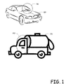
- FIG. 1 is a conceptual diagram of exemplary areas that define the driver's ROI.
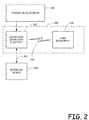
- FIG. 2 is a system diagram illustrating the elements of one exemplary embodiment.
- FIG. 3 is a flow diagram illustrating an exemplar operation of the system illustrated in FIG. 2 .
- FIG. 4 is a system diagram illustrating the elements of another exemplary embodiment.
- FIG. 5 is a system diagram illustrating the elements of another exemplary embodiment that includes a combination of the systems illustrated in FIG. 2 and FIG. 4 .
- FIG. 6 is a functional block diagram of the components of an exemplary device that can incorporate one or more aspects of the various embodiments and that may be used in implementing aspects of the embodiments.
- FIG. 7 is a schematic diagram, which shows the various forces that are acting on a vehicle.
- FIG. 8 is a flow diagram illustrating exemplary actions that can be taken by an exemplary algorithm used to calculate the speed of a vehicle utilizing an accelerometer to obtain input information.
- This disclosure presents various embodiments, as well as features and aspects thereof, directed towards providing a solution that disables distracting activities while driving a vehicle.
- One of the challenges in such a solution is to be able to identify the driver's equipment (e.g., cellular telephone, BLACKBERRY, IPAD, IPHONE, e-mail or text messaging or web-surfing device, GPS, etc.).
- the driver's equipment e.g., cellular telephone, BLACKBERRY, IPAD, IPHONE, e-mail or text messaging or web-surfing device, GPS, etc.
- one aspect that can be included in various embodiments is the ability to identify equipment utilized by the driver and disable that equipment. For instance, it should be a goal to disable the activities of the driver but to still allow the other occupants of the vehicle to utilize their equipment for such activity.
- cars that include a built in BLUETOOTH functionality may use this capability to automatically connect the correct person's handset to the BLUETOOTH functionality (e.g., the driver's handset to the speaker/microphone system in driver's side).
- tag is used to represent an RFID tag or any short-range wireless transmitter.
- detector is used to represent an RFID detector or any wireless receiver capable of detecting the wireless transmitter, such as a tag.
- driver's quadrant or driver's region of interest (“driver's ROI”) is used to represent the region that is proximate, close to or surrounding the driver (i.e., the space that is usually associated as being within the driver's reach or “belonging to the driver” or some space within which the tag or detector used to identify the driver can be placed).
- FIG. 1 is a conceptual diagram of exemplary areas that define the driver's ROI. Vehicle 100 is shown as including an ROI 110 and vehicle 120 illustrates ROI 130 . It should be appreciated that any motorized vehicle, such as an automobile, truck, motorcycle, boat, plane, etc. could benefit from the disclosed embodiments as well as non-vehicle equipment such as heavy machinery, farm equipment, etc.
- the driver's ROI although illustrated as being on the left side of the car, could also be on the right side for other countries.
- the ROI could be any particular region within the vehicle, such as in back of a fire truck, in the engine room of a train, or even relative to critical zones around equipment that is being operated (such as at the entrance chute of a wood chipper machine, etc.
- the disclosure refers to the detector “identifying” the tag.
- “identify” means more than just sensing the tag.
- Many techniques such as signal strength/signal-to-noise ratio (SNR), time of arrival, etc., can be used to detect the proximity of the tag.
- wireless technologies e.g., RF/RFID, UWB, BLUETOOTH
- RF/RFID radio frequency identification
- UWB ultrasonic wave ratio
- BLUETOOTH wireless technologies
- Different algorithms may be incorporated to identify the tag correctly.
- time diversity may be incorporated in detecting the correct tag. This technique operates by combining/averaging the signals over time, using specific correlation receivers, or by requiring N subsequent detections of the same handset as a driver's handset before actually recognizing/identifying it as the driver's), or
- Handset refers to an electronic device, usually with a transmitter and receiver (or transceiver) used for various types of personal communications.
- personal communications may include, but are not limited to e-mail, text-messaging/SMS, Internet surfing/download/upload or/and storage of information, TWEETS, FACEBOOK postings, blog postings, etc.
- PDA personal data assistants
- wireless computers such as iPhones, iPads, ANDROIDS, BLACKBERRYS, etc.
- the term “distracting functionalities/services” is used to describe any or a combination of those handset functionalities or services that may be distracting to the user while driving, such as text messaging, Internet, typing, E-mail, keyboard/touch screen, certain communication functionalities, or notifications such as sounds/messages/displays/vibrations, etc.
- the various embodiments presented herein operate to restrict or prevent distractions to the operator of a vehicle by (a) defining conditions under which such distractions could be problematic, (b) detecting when the conditions are satisfied, and then (c) restricting operations of the user equipment when such conditions are satisfied.
- FIG. 2 is a system diagram illustrating the elements of one exemplary embodiment.
- the illustrated system 200 includes a condition detection function 220 that interfaces to the user equipment 230 over a communications link 240 .
- the communications link 240 may include any of a variety of wireless or wired technologies, including but not limited to, INFRARED, BLUETOOTH, WiFi, RF, etc.
- the condition detection function 220 interfaces to the vehicle or equipment 210 to detect if and when conditions are satisfied for imposing restrictions on the operation of the user equipment 230 .
- the conditions can be preprogrammed into the condition detection function 220 , can be hardcoded into the software of the condition detection function, can be embedded as part of the circuitry/hardware of the condition detection function 220 (such as a chip or series of chips or a plug in module such as a USB jump drive etc.) or can be loaded into the condition detection function 220 by a user/operator. For instance, if the vehicle is operated by a child, the parent could define and program the conditions into the condition detection function 220 using interface device 250 through programming interface 260 .
- the condition detection function may include a direct interface to allow programming of the conditions, such as a keypad and display as a non-limiting example.
- the user equipment 230 or a similar device could be used to program the conditions into the condition detection function over the communications link 240 .
- the ability to program the conditions into the condition detection function may be password protected or use some other security or anti-tampering technology to prevent the operation of the condition detection function from being inhibited, disabled, spoofed or otherwise altered.
- condition detection function 220 may be incorporated into a car-pluggable device that can be inserted into a cigarette lighter receptacle (12 volt receptacle) and includes a BLUETOOTH communication system for interfacing to a BLUETOOTH enabled user equipment 230 .
- condition detection function 220 may be a device installed within the vehicle, such as a car-PC apparatus within the console or otherwise installed within the vehicle.
- car-PC or other device may include BLUETOOTH communications technology for interfacing to a BLUETOOTH enabled user equipment 230 .
- the car-PC detects conditions, such as speed by reading the vehicle speedometer via the internal bus of the vehicle. The car-PC then imposes the restrictions on the user equipment 230 .
- FIG. 3 is a flow diagram illustrating an exemplar operation of the system illustrated in FIG. 2 .
- the exemplary operation 300 when commenced, may, in necessary, first include the action of obtaining programming conditions 310 . As previously described, this can be preprogrammed into the condition detection function 220 prior to operation or can be programmed by a user/operator at any time once the system is in use depending on the particular embodiments. For instance, a rental car company may evaluate a potential renter, their driving record, their age, their insurance coverage etc., and program the condition detection device accordingly. Likewise, an insurance company may impose or program certain conditions into the condition detection function 220 .
- Other examples also include, but are not limited to, parents, companies, agencies, etc., imposing or programming conditions into the condition detection function 220 .
- the action of obtaining programming conditions 310 can be accomplished at the time of building the system components and not a part of normal operation.
- the processing unit can read the programming conditions.
- the condition detection function may also operate to detect the user equipment 230 .
- This action can be performed in a variety of manners and may be autonomous, automatic, manual, etc., or a combination of a variety of techniques.
- a BLUETOOTH peer-to-peer signaling exchange may be utilized by the condition detection function 220 to identify user equipment 230 that is proximate to the condition detection function 220 .
- the condition detection function 220 may utilize technology to determine the location of the user equipment 230 relative to the driver's ROI.
- condition detection device can prevent operation of the vehicle until the operator keys in his or her user equipment identification number (such as a mobile number, MIN, etc.) into the condition detection device and/or registers the user equipment 230 therewith.
- the condition detection function 220 may simply operate on all user equipment that is within the communication range of the condition detection function 220 .
- the user equipment 230 may be plugged or connected directly to the condition detection function 220 .
- the condition detection function 220 then commences to monitor for conditions 330 .
- the conditions can be any of a variety of conditions and combinations thereof, including but not limited to, motion of the vehicle, speed of the vehicle, time of day, location of the vehicle, type of the vehicle, identification of the operator, etc. If conditions are detected that invoke the imposition of restrictions 350 , then the condition detection function 220 causes the restrictions to be imposed on the user equipment 230 and then continues to monitor for conditions 330 .
- the conditions may be evaluated to determine if removal of the imposition of restrictions is warranted 360 . If the conditions warrant the removal of restrictions, then any or specific restrictions imposed on the user equipment 230 are removed 370 and the condition detection function 220 again returns to monitor for conditions 330 . Although not illustrated, this operation may continue in a loop until a triggering event occurs, such as the vehicle is turned off, the user equipment 230 is removed from the vicinity of the condition detection function 220 , etc.
- FIG. 4 is a system diagram illustrating the elements of another exemplary embodiment.
- the illustrated system 400 includes a condition detection function 420 that may or may not interface to the user equipment 430 over a communications link 440 depending on the particulars of the embodiment.
- the condition detection function 440 interfaces to the vehicle or equipment 410 to detect if and when conditions are satisfied for imposing restrictions on the operation of the user equipment 430 .
- the conditions can be preprogrammed into the condition detection function 420 or can be loaded into the condition detection function 420 by a user/operator (not illustrated in FIG. 4 ).
- the condition detection function 420 interfaces with a user equipment operator interface 465 , which in turn interfaces to operator equipment 470 over communications link 480 .
- the user equipment operator interface may be as simple as a signal transmitter the receives a signal from the condition detection function 420 and transmits it to the operator equipment 470 , or it may be a complicated device that can engage in communication with the conditions detection function 420 and determine what, if any messages should be sent to the operator equipment 470 .
- some or all of the condition detection functionality can be incorporated into the user equipment operator interface 465 . As such, in some embodiments, the user equipment operator interface 465 may supplant the condition detection function 420 altogether.
- the operator equipment 470 which in the illustrated example is shown to be a mobile terminal switching operator and/or office (MTSO) as a non-limiting example, communicates with the user equipment 430 over one or more communication links 495 and through communication equipment 490 to impose restriction or relinquish the imposition of restrictions on the user equipment 430 .
- MTSO mobile terminal switching operator and/or office
- condition detection function 420 may be incorporated into a car-pluggable device that can be inserted into a cigarette lighter receptacle (12 volt receptacle) and includes an interface to a GPRS/EDGE/LTE/WiMAX or other similar device that communications with the operator equipment.
- the car-pluggable device detects conditions, such as the car being in motion and through the embedded or attached cellular modem signals the mobile operator that the driver is in motion. The mobile operator then holds all SMS messages from being forwarded to the user equipment 430 .
- condition detection function 220 may be a device installed within the vehicle, such as a car-PC apparatus within the console or otherwise installed within the vehicle.
- car-PC or other device may include an interface to a GPRS/EDGE/LTE/WiMAX or other similar device that communications with the operator equipment.
- the car-PC detects conditions, such as speed by reading the vehicle speedometer via the internal bus of the vehicle.
- the car-PC then through the embedded or attached cellular modem signals the mobile operator that the driver is in motion.
- the mobile operator then holds all SMS messages from being forwarded to the user equipment 530 .
- FIG. 3 The operation of FIG. 3 is now revisited in view of illustrating an exemplar operation of the system illustrated in FIG. 4 .
- the exemplary operation 300 includes the action of programming conditions 310 . As previously described, this can be preprogrammed into the condition detection function 420 or can be programmed by a user/operator.
- the condition detection function may also operate to detect the user equipment 430 .
- This action can be performed in a variety of manners and may be autonomous, automatic, manual, etc., or a combination of a variety of techniques.
- a BLUETOOTH peer-to-peer signaling exchange may be utilized by the condition detection function 420 to identify user equipment 430 that is proximate to the condition detection function 420 .
- the condition detection function 420 may utilize technology to determine the location of the user equipment 430 relative to the driver's ROI.
- condition detection device can prevent operation of the vehicle until the operator keys in his or her user equipment identification number (such as a mobile number, MIN, etc.) into the condition detection device and/or registers the user equipment 430 therewith.
- the condition detection function 420 may simply operate on all user equipment that is within the communication range of the condition detection function 420 .
- the user equipment 430 may be plugged or connected directly to the condition detection function 420 .
- the condition detection function 420 then commences to monitor for conditions 330 .
- the conditions can be any of a variety of conditions and combinations thereof, including but not limited to, motion of the vehicle, speed of the vehicle, time of day, location of the vehicle, type of the vehicle, identification of the operator, etc. If conditions are detected that invoke the imposition of restrictions 350 , then the condition detection function 420 sends notification to the operator equipment 470 through the user equipment operator interface 465 and communications link 480 . The operator equipment 470 may then operate to cause the restrictions to be imposed on the user equipment 430 through the communications links 495 and infrastructure equipment 490 . The condition detection function 420 then continues to monitor for conditions 330 .
- the conditions may be evaluated to determine if removal of the imposition of restrictions is warranted 360 . If the conditions warrant the removal of restrictions, then the condition detect function 420 sends notification to the operator equipment 470 through the user equipment operator interface 465 and communications link 480 . The operator equipment 470 may then operate to cause the restrictions to be removed from the user equipment 430 through the communications links 495 and infrastructure equipment 490 . Although not illustrated, this operation may continue in a loop until a triggering event occurs, such as the vehicle is turned off, the user equipment 430 is removed from the vicinity of the condition detection function 420 , etc.
- FIG. 5 is a system diagram illustrating the elements of another exemplary embodiment that includes a combination of the systems illustrated in FIG. 2 and FIG. 4 .
- the illustrated system 500 includes a condition detection function 520 that may or may not interface to the user equipment 530 over a communications link 540 depending on the particulars of the embodiment.
- the condition detection function 540 interfaces to the vehicle or equipment 510 to detect if and when conditions are satisfied for imposing restrictions on the operation of the user equipment 530 .
- the conditions can be preprogrammed into the condition detection function 520 or can be loaded into the condition detection function 520 by a user/operator (not illustrated in FIG. 5 ).
- the condition detection function 520 interfaces with a user equipment operator interface 565 , which in turn interfaces to operator equipment 570 over communications link 580 .
- the user equipment operator interface may be as simple as a signal transmitter the receives a signal from the condition detection function 520 and transmits it to the operator equipment 570 , or it may be a complicated device that can engage in communication with the conditions detection function 520 and determine what, if any messages should be sent to the operator equipment 570 .
- some or all of the condition detection functionality can be incorporated into the user equipment operator interface 565 . As such, in some embodiments, the user equipment operator interface 565 may supplant the condition detection function 520 altogether.
- the operator equipment 570 which in the illustrated example is shown to be a mobile telephone switching operator and/or office (MTSO) as a non-limiting example, communicates with the user equipment 530 over one or more communication links 595 and through communication equipment 590 to impose restriction or relinquish the imposition of restrictions on the user equipment 530 .
- MTSO mobile telephone switching operator and/or office
- FIG. 3 The operation of FIG. 3 is now revisited in view of illustrating an exemplar operation of the system illustrated in FIG. 5 .
- the exemplary operation 300 includes the action of programming conditions 310 . As previously described, this can be preprogrammed into the condition detection function 520 or can be programmed by a user/operator.
- the condition detection function may also operate to detect the user equipment 530 .
- This action can be performed in a variety of manners and may be autonomous, automatic, manual, etc., or a combination of a variety of techniques.
- a BLUETOOTH peer-to-peer signaling exchange may be utilized by the condition detection function 520 to identify user equipment 530 that is proximate to the condition detection function 520 .
- the condition detection function 520 may utilize technology to determine the location of the user equipment 530 relative to the driver's ROI.
- condition detection device can prevent operation of the vehicle until the operator keys in his or her user equipment identification number (such as a mobile number, MIN, etc.) into the condition detection device and/or registers the user equipment 530 therewith.
- the condition detection function 520 may simply operate on all user equipment that is within the communication range of the condition detection function 520 .
- the user equipment 530 may be plugged or connected directly to the condition detection function 520 . It should also be appreciated that the user equipment 530 (in this and in other embodiments) may be linked or associated with the condition detection function 520 by the operator equipment 570 .
- the operator equipment 570 may associate the user equipment 530 with a particular condition detection function 520 . This can be accomplished in a variety of manners including identifying the location of the user equipment 530 and the condition detection function 520 , or one or more of the condition detection function 520 and user equipment 530 can detect the other and provide this information to the operator equipment 570 .
- the condition detection function 520 then commences to monitor for conditions 330 .
- the conditions can be any of a variety of conditions and combinations thereof, including but not limited to, motion of the vehicle, speed of the vehicle, time of day, location of the vehicle, type of the vehicle, identification of the operator, etc. If conditions are detected that invoke the imposition of restrictions 350 , then the condition detection function 520 may impose the restrictions on the user equipment 530 . In addition or alternatively, the condition detection function 520 may send notification to the operator equipment 570 through the user equipment operator interface 565 and communications link 580 . The operator equipment 570 may then operate to cause the restrictions to be imposed on the user equipment 530 through the communications links 595 and infrastructure equipment 590 . The condition detection function 520 then continues to monitor for conditions 330 .
- the conditions may be evaluated to determine if removal of the imposition of restrictions is warranted 360 . If the conditions warrant the removal of restrictions, then the condition detect function 520 removes the restrictions on the user equipment 530 and/or sends notification to the operator equipment 570 through the user equipment operator interface 565 and communications link 580 . The operator equipment 570 may then operate to cause the restrictions to be removed from the user equipment 530 through the communications links 595 and infrastructure equipment 590 .
- the condition detection function 520 and the operator equipment 570 may impose restrictions, may share the responsibility for imposing the restrictions, or may be assigned certain capabilities for restricting the operation of the user equipment 530 . Although not illustrated, this operation may continue in a loop until a triggering event occurs, such as the vehicle is turned off, the user equipment 530 is removed from the vicinity of the condition detection function 520 , etc.
- One operational configuration includes fully or partially disabling user equipment functions via a detachable/pluggable apparatus (e.g. pluggable into the cigarette lighter slot).
- the pluggable apparatus may contain a velocity sensor (such as an accelerometer or global positioning system function) and a BLUETOOTH wireless transceiver to signal that motion of the vehicle has been detected and notify the user equipment of such conditions.
- This operational configure can include software and/or hardware functionality in the user equipment to detect and authenticate the alert of the pluggable apparatus (condition detection function) “car-in-motion” in order to disable functionality of the user equipment, such as the notification of receipt of an incoming text message.
- a BLUETOOTH peer-to-peer software protocol may be utilized to enable this to happen.
- Another operational configuration operates to fully or partially disable functions of the user equipment via a detachable/pluggable apparatus (e.g. pluggable into the cigarette lighter slot).
- the pluggable apparatus may contain a velocity sensor and a cellular modem radio to signal that motion of the vehicle has been detected and notify the user equipment of such condition through available GSM and/or other cellular protocols and channels used for the delivery of data, such as GPRS and Edge so that the operator can disable functions of the user equipment or prevent certain data from being sent to the user equipment, such as putting a hold on all SMS message forwarding to the user equipment.
- Another operational configuration includes fully or partially disabling user equipment functions (such as SMS messaging features) utilizing the speedometer reader in a car computer and through a BLUETOOTH wireless transceiver, built-in or plugged into the car computer.
- the car computer then signals the condition being met (such as the vehicle being in motion or exceeding a threshold speed) to the user equipment and, the user equipment then self-imposes the restriction of the function.
- This operational configuration may utilize software and/or hardware functionality within the user equipment to detect and authenticate the alert of the condition detection function that the condition(s) is met prior to disabling the function(s), such as notification of receipt of incoming text messages.
- a BLUETOOTH peer-to-peer software protocol enables this capability.
- Yet another operational configuration operates to fully or partially disable functions of the user equipment by utilizing the speedometer reader in a vehicle computer and through a radio modem to wirelessly signal that the conditions have been met, such as motion of the vehicle and/or threshold speeds of the vehicle to the operator equipment through available channels.
- the channels may include GSM and other cellular protocols and channels used for the delivery of data, such as GPRS and Edge so that the Mobile operator can restrict the functionality of the user equipment, such as putting a hold on all SMS messages forwarded to a cellular telephone user equipment.
- Motion sensing can be provided in a variety of manners in various embodiments and, one or more of the techniques may be incorporated into the various embodiments. On technique is by the use of accelerometers. Accelerometers are useful in detecting velocity, such as the speed and direction of motion. Multiple accelerometers may be used to detect motion in various planes. For instance, the X-Y plane may be used to indicate forward and backward motion. The Z plane can be added to identify when the vehicle is turning. Further, the Z plane can be used in aircraft to determine if the aircraft is ascending or descending. GPS technology may also be used to detect motion and velocity. The speedometer of the vehicle may also be used to detect motion and velocity. In aircraft, other devices may be used to detect altitude, air speed, etc. Similarly, speedometer technology employed in marine vehicles may also be utilized as well as the above-listed technologies.
- BLUETOOTH peer-to-peer is a communication standard protocol that has been established by standards bodies to allow wireless data transfer of devices using BLUETOOTH wireless radio.
- the device detecting a motion such as the condition detection function, may establish a peer-to-peer session with the user equipment (i.e., a cellular telephone as a non-limiting example).
- the cellular telephone may utilize a software application running within the cellular telephone and/or hardware that will allow this peer-to-peer communication to happen.
- the software application and/or hardware may further authenticate the transmitting device and interpret its message.
- the application and/or hardware may then disable a feature or features of the cellular telephone, such as the notification feature of the SMS receiving routine.
- a feature or features of the cellular telephone such as the notification feature of the SMS receiving routine.
- the two devices communicating the protocol need to be paired up initially so that subsequent authentications may occur successfully.
- condition detection function communicates to the operator equipment through a data modem offered and/or authorized by the operator itself.
- the modem and the service is readily available and do not need to be created but, as mentioned above, new technologies may be created for such capabilities.
- One exemplary embodiment may provide a near real-time messaging and alerting system for detecting a motor vehicle in motion, and further disabling the SMS text messaging features of the driver's mobile (cellular) telephone.
- a car pluggable apparatus and a wireless communication protocol between said apparatus and mobile telephone are employed.
- the apparatus includes an accelerometer to detect speed and direction and/or velocity of the vehicle.
- the communication protocol is utilized to send signals to the mobile telephone to cause the disablement of the SMS text messaging features of the driver's mobile telephone.
- Another exemplary embodiment may provide a near real-time messaging and alerting system for detecting a motor vehicle in motion, and further disabling the SMS text messaging features of the driver's mobile (cellular) telephone.
- a vehicle installed computer or entertainment and control center utilizes a wireless communication protocol between the vehicle computer and the mobile telephone.
- the vehicle computer may include a connection to the internal vehicle signals to detect and receive the vehicle speed. Through the transmission of signals utilizing the communication protocol, the vehicle computer can invoke the disablement of the SMS text messaging features of the driver's mobile telephone.
- a car pluggable apparatus includes an accelerometer to detect speed and direction and/or velocity of the vehicle and a radio data modem compatible with operating cellular channels and in communication with a mobile operator. The motion of the motor vehicle is detected and signals conveying such information are transmitted to the mobile operator using said data modem. The mobile operator then operates to disable SMS test messages from being forwarded to driver's mobile telephone.
- a vehicle installed computer or entertainment and control center includes a connection to the internal vehicle signals for reading or detecting the car speed.
- a radio data modem is attached to or embedded within the vehicle computer and is compatible with an operating cellular channels and in communication with a mobile operator. The motion of vehicle is detected and signals conveying such information are transmitted to the mobile operator using said data modem. The mobile operator then operates to disable SMS text messages from being forwarded to driver's mobile phone.
- Another exemplary embodiment may provide a method for disabling the SMS text messaging notification features of mobile telephones using a BLUETOOTH wireless peer-to-peer protocol between a commanding device and the mobile telephone.
- the method includes initializing the BLUETOOTH technology to create a pairing between the commanding device and the mobile telephone.
- a messaging session includes sending a prescribed command to the mobile telephone from the commanding device.
- An authentication routine may be executed by the mobile telephone to authenticate the prescribed command.
- a command interpretation and execution routine then disables the alerting and notification of SMS text messages received by the mobile telephone.
- One aspect or function that can be incorporated into various embodiments is the use of RFID technology for the detection of the user equipment and verification of user equipment within the driver's ROI.
- An exemplary technique to enable this capability is through the use of a tag and detector, such as an RFID tag and detector as a non-limiting example.
- the tag can be embedded within, connected physically or wirelessly to, or simply be proximate to the user equipment. In such a configuration, the detector can then be placed in or near the driver's ROI. In other embodiments, the detector can be embedded within, connected physically or wirelessly to, or simply be proximate to the user equipment. In such a configuration, the tag can be placed within the driver's ROI.
- the detection of the tag by the detector based on specific algorithms is used to “identify” the user equipment as being within the driver's ROI.
- This information by itself or combined with other information (such as detection of motion, the engine being on, the RPM of the motor, the speed of the vehicle, the gear position/status, geo-location/GPS/triangulation algorithms, etc.) can be used as a condition to turn on or off certain functionality of the user equipment (ie., text messaging, Internet access, call restriction and/or other keyboard/touch screen functionalities that are unsafe during driving).
- a device external to the user equipment sends out an excitement signal which triggers the tag to transmit its signal.
- the detector can be located in the driver's ROI and detect that a tag associated with the user equipment has transmitted its signal and thereby conclude that the user device is within the driver's ROI. If the tag is external to the user equipment, the user equipment may send out an excitement signal. The user equipment or an external device can then detect the transmission of the tag and the excitement signal and determine that the user equipment is within the driver's ROI.
- RFID stands for radio frequency identification. It is an automatic identification technology whereby digital data encoded in an RFID tag or “smart label” is captured by a detector using radio waves. In essence, RFID is similar to bar code technology but uses radio waves to capture data from tags, rather than optically scanning the bar codes on a label. RFID does not require the tag or label to be seen to read its stored data. Information is sent to and read from RFID tags by a detector or reader using radio waves. In passive systems, which are the most common, an RFID reader transmits an energy field that “wakes up” the tag and provides the power for the tag to respond to the reader. In active systems, a battery in the tag is used to boost the effective operating range of the tag and to support additional features over passive tags, such as temperature sensing.
- Passive smart label RFID systems offer unique capabilities as an automatic data capture system in that they: provide real-time, wireless transmission of data without human intervention; do not require line-of-site scanners for operation; allow stored data to be altered during sorting or allow workflow process information to be captured with the data; and work effectively even in harsh environments with excessive dirt, dust, moisture, and extreme temperatures.
- the detector/reader in an RFID based embodiment may send out a signal to detect all tags in the vicinity and based on the information received, determine what user equipment is within a defined zone and operate accordingly. It should be appreciated that some tags are active, meaning they can transmit their signals without being excited or actuated, while other tags are passive meaning that they transmit their signal only when excited or actuated. Throughout the description, it should be appreciated that either technology could be used and any reference to “detecting” a tag or sending a signal to “activate a tag” should be assumed to be only an example of one particular type of tag but, the other technology could be substituted as well. Thus, if the navigation system for a vehicle includes a tag, the system may detect such and choose to not disable any functions of the navigation system or simply to ignore that tag. However, if a cellular telephone is detected, certain features of the cellular telephone may be disabled.
- a detector/reader within the user equipment can send out a signal to determine if a user equipment restriction tag is in the same zone as the user equipment. If the vehicle includes multiple tags, the ID of a user equipment restriction tag may be pre-programmed into the user equipment. As another example, if multiple tags are located within the range of the user equipment, the user equipment can analyze the tag signals to determine which zone the user equipment is within.
- RFID technology may also be employed for the detection of user equipment and the use of RFID technology is simply one non-limiting example.
- Other technologies may include, as non-limiting examples, BLUETOOTH pairing, any RF based handshaking protocol such as transmissions in the unlicensed frequency spectrum, INFRARED technology, Ultra Wideband technology, Impulse Radio Technology, Personal Area Networks, etc.
- the vehicle may be equipped with small transmitters located at various locations within the vehicle.
- the use of triangulation technology may be used within the vehicle by various components of the system (i.e., the user equipment) to determine if the user equipment is within the driver's ROI.
- camera systems can be set up within the vehicle to visually monitor the location of user equipment and define zones within the vehicle.
- any user equipment that is in the proximity of the vehicle may be detected and controlled.
- the detection and control can be as simplistic as a Boolean operation: if user equipment is in vicinity, disable certain functions, or the detection and control can be more robust by being based on various conditions, parameters and heuristics.
- the user equipment detection function can define the ROI and only operate to control user equipment within that ROI. Further, only certain classes of user equipment within the ROI may be subjected to control. In addition, the user equipment within the ROI may be totally disabled or, only portions of the functionality may be disabled, or the user equipment may be totally or partially disabled based on various other conditions.
- multiple zones can be defined within the vehicle and user equipment may be controlled depending upon which zone it resides. For instance, user equipment within the driver's ROI may be restricted at a first level, user equipment in the front seat may be controlled at a second level, user equipment in the rear of the vehicle may be controlled at yet a third level, etc.
- tags or detectors may be installed in various locations such as the steering wheel, driver's door, under driver's seat, in the visor, in the headliner, as well as throughout the vehicle in various other locations.
- various embodiments may operate to continuously monitor and assess the location of user equipment and apply restriction control based on current positions. For instance, user equipment that is located in the driver's ROI may be disabled from answering an incoming call but may still signal a ring tone to indicate that a call is being received. If the user equipment is passed into a different zone, the restrictions may be relaxed thus allowing a passenger to answer the incoming call.
- the condition detector function can operate to detect one or more of a variety of operational and environmental conditions of the vehicle or equipment that is associated with the various embodiments.
- a variety of technologies may be utilized for detecting such operational and/or environmental conditions. A few non-limiting examples are provided in this section.
- accelerometer technology can be used to detect motion, velocity, speed, etc. of the vehicle.
- Using accelerometer technology can be accomplished by an accelerometer that is embedded within the user equipment, the vehicle, or a within a device to which the user equipment and/or vehicle interface.
- the accelerometer may be embedded within or coupled to the tag, the detector, the condition detection function, the vehicle computer system etc.
- GPS global positioning system
- the use of the global positioning system may also be used to detect motion, speed, velocity, location, etc. of the vehicle.
- the GPS technology can embedded within the user equipment, the vehicle, or a within a device to which the user equipment and/or vehicle interface.
- the accelerometer may be embedded within or coupled to the tag, the detector, the condition detection function, the vehicle computer system etc.
- Triangulation operates by detecting signals, usually three or more, that are transmitted from known locations, such a mobile telephone towers. By analyzing the propagation characteristics of the received signals, the location of the vehicle can be identified. By taking period samples and comparing the results, the direction, speed, motion, velocity, etc., of the vehicle can be determined.
- OBD is an acronym for On-Board Diagnostic System.
- OBD technology was birthed out of a desire to operate vehicles is a more environmental friendly manner.
- the technology introduced various sensors and data communications capabilities within the vehicle to enable the detection of problems that may result in environmentally unfriendly operation of the vehicle.
- a typical OBD system includes an engine control module (ECM) that monitors critical and emission related components for proper operation and triggers an alarm condition (i.e., illuminating an indicator lamp on the instrument panel) when a malfunction is detected.
- ECM engine control module
- the OBD system also provides for a system of diagnostic trouble codes (DTC) and fault isolation logic charts to assist technicians in determining the likely cause of engine control and emissions system malfunctions.
- DTC diagnostic trouble codes
- OBD-II add and enhance the vehicle operation monitoring capabilities.
- Some of the monitoring capabilities in OBD-II include throttle position sensor, idle air control valve, oxygen sensors, manifold absolute pressure sensor, etc.
- Today, many operational features are all interconnected within a data bus system within a vehicle and interconnected with an in-vehicle computer.
- the in-vehicle computer can monitor the data over the bus to determine a variety of information including vehicle speed, miles traveled, driving statistics, braking statistics, operation of head lamps, seat belts, entertainment systems, windshield wipers, etc.
- embodiments that exploit this technology can be used to obtain operational information of the vehicle such as the engine being on or off, the RPM, the speed, gear positions, etc.
- Another technology that can be employed is the use of video cameras integrated within or installed within the vehicle.
- the audio detectors and cameras can be used to monitor internal events and external events.
- the cameras, along with video processing technology and a processing unit can determine the speed of the vehicle by monitoring the speed at which objects external to the vehicle are passed or by looking at the speedometer. It will be appreciated that such technology may also be utilized to identify a variety of other operational and environmental characteristics such as time of day, ambient light, weather conditions, noise level within the vehicle, etc.
- any of the embodiments and variants thereof may utilize one or more accelerometers to detect movement and/or speed of a vehicle.
- an algorithm is presented following that presents one technique that can be used to determine movement and/or speed of the vehicle using the accelerometer.
- FIG. 7 shows the various forces that are acting on a vehicle. At any given moment, two main forces act on objects inside a vehicle. These forces are represented as follow:
- the speed of the vehicle can be determined by from data collected or received from one or more accelerometers and analyzed in view of the above-listed forces.
- a processing unit receives readings from an accelerometer. These readings are represented as follows:
- the algorithm operates by initially calculating ⁇ right arrow over (a) ⁇ g (0) and then finding the sum of the square of the absolute values of ⁇ right arrow over (a) ⁇ int as follows: ⁇
- 2 which is the high frequency energy (E h ) while car is not moving.
- speed will be calculated periodically or a periodically.
- the algorithm may operate to calculate the speed approximately every 0.1 sec.
- the high frequency energy is also calculated.
- the value of ⁇ right arrow over (a) ⁇ g (t) can be recalculated or updated.
- FIG. 8 is a flow diagram illustrating exemplary actions that can be taken by an exemplary algorithm used to calculate the speed of a vehicle utilizing an accelerometer to obtain input information.
- the speed is calculated and adjusted, if necessary, periodically (i.e., every 0.1 seconds as a non-limiting example 808 ).
- This function operates to determine if the magnitude of the effective acceleration equals that of time zero (no motion condition) 810 . If so, then it is determined that the gravitation angle has changed and thus the change in gravitational acceleration vector can be calculated and adjustments are made by overwriting the value as follows:
- the process checks to see if the motion has stopped 816 .
- Stopped can be defined as absolutely zero movement or can approximate zero movement (i.e., approximately less than 5 km/hour for more than approximately 0.5 seconds as a non-limiting example)
- S i ⁇ 0 and E h (i) is within 98% of E h (0) for at least approximately 1 second indicating that the vehicle is not receiving any forces due to bumps from moving on the terrain because the energy at E h (i) approximates the energy of E h (0) when the vehicle was not moving. If the vehicle has stopped moving, then the process is reinitialized 802 . Otherwise, the speed is continuously calculated 808 .
- the restrictions can be applied to relevant user equipment. Further, when the condition detection function determines that the conditions have changed or have been relinquished, new restrictions can be applied or all restrictions may be removed as appropriate. In some embodiments, a time delay may be imposed on the removal of restrictions thus requiring the conditions to be removed or the user equipment to be out of the driver's ROI for a required period of time before the restrictions are relaxed or removed. It should be appreciated that a wide variety of conditions and restrictions can be applied in various embodiments and conditions and can depend upon a wide array of factors. The present disclosure anticipates this and as such, applies in any such configuration.
- the detector uses this information by itself or combined with any other information (such as detection of motion, engine being on, RPM, speed of the vehicle, gear position/status, geo-location/GPS/triangulation algorithms, etc.) to do one or a combination of two or more, as well as other functions, including the following:
- the detector is communicatively coupled with the user equipment using any of a variety of communication technologies.
- the communication technologies may include wireless technologies, such as a BLUETOOTH transmitter integrated with/connected to the detector and communicating with the user equipment, instructing it (or software applications or hardware functions within the user equipment) to disable the distracting functionalities.
- the detector may communicate with a communications system operator that controls the delivery of communications to the user equipment to request the disablement of such functions.
- the detector may communicate using any of a wide variety of communication technologies with the mobile telephone service operator or carrier to request disabling of any or any combination of the “distracting functionalities/services”.
- a cellular modem may be embedded or connected to the detector, which would be used to inform the mobile operator (e.g., via SMS or other services), or a BLUETOOTH transmitter/modem connected to or embedded within the detector unit would communicate with the driver's handset, which would in turn communicate with the mobile provider in order to temporarily disable the distracting functionalities/services.
- embodiments may perform other actions or functions under certain conditions. For instance, if certain conditions are active, an embodiment may operate to perform an action to warn (e.g., by using sound/noise, lights, vibration, etc.) the driver or others in or around the vehicle (e.g., warning the other cars by sounding the horn, flashing of the lights, etc.) of the existence of the conditions. For example, if the driver engages in risky behavior, such as texting while driving, such an embodiment can operate to perform actions such as sounding the horn, turning on hazard lights, flashing the headlights, etc. to provide an alert to nearby driver's to be cautious when approaching this vehicle.
- risky behavior such as texting while driving
- such an embodiment can operate to perform actions such as sounding the horn, turning on hazard lights, flashing the headlights, etc. to provide an alert to nearby driver's to be cautious when approaching this vehicle.
- Such actions may also be used to alert other passengers in the car, especially a sleeping passenger, of the perilous activity and allow them the opportunity to take remedial action, such as request the driver to stop the dangerous activity.
- the detector is a pluggable unit
- the pluggable unit itself can have flashing lights and sounds to gain the driver's or others' attention, and in case of Bluetooth or other wireless communication with the handset, the handset can inform of the driver's risky behavior via sounds, vibration, etc.
- embodiments may operate to inform a third party of the dangerous activity thus allowing others to take remedial measures or to levy consequences for the behavior. For instance, if the driver is engaged in the activity of texting while driving, the driver's parents can be notified via a text message. Similarly, the driver's insurance company or law enforcement officials can also be notified of the activity. Thus, it will be appreciated that in any of the embodiments described herein, the application of the various technologies can enable the third party to be notified.
- a log can be kept by one or more of the components of the system to identify if and when dangerous activities were conducted. This log can be down loaded automatically to parents, insurance companies, etc., or simply requested from time to time.
- the various embodiments can operate to remove and/or change the restrictions and/or provide follow-up warnings or notifications.
- the detector can communicate with the handset to enable any or any combination of the previously applied restrictions.
- the detector can communicate with the service operator of the user equipment (i.e., a mobile telephone system operator) to request the removal of the restrictions on the user equipment.
- the embodiment can cease or remove the application of the warning signals that may be active and/or send a communication to the third party indicating the removal or change of the conditions.
- the system may operate to simply detect the presence of user equipment within the driver's ROI and then disable some or all functions of the user equipment.
- they system may operate to detect the presence of user equipment within the driver's ROI and then if one or more additional conditions are met, then operate to disable some or all functions of the user equipment. For instance, if the user equipment is in the driver's ROI and the car is moving, text-messaging can be disabled.
- the tag can be attached to or integrated with the user equipment (e.g., placed on or built into the user equipment or another unit within the user equipment such as a SIM card for a cellular telephone).
- the detector is available either as an external apparatus (can be a unit pluggable into the vehicle's electric outlet or battery operated), or can be integrated into the car's components (e.g., car's built in GPS, car's computer, etc.). The detector is placed within or built in within the Driver's ROI.
- the signal-to-strength ratio (SNR greater than a certain threshold) is used to detect the presence of a tag within certain proximity of the detector.
- SNR greater than a certain threshold is used to detect the presence of a tag within certain proximity of the detector.
- signal averaging or/and other algorithms may be incorporated. For example, several N consecutive detections of the same tag (with SNR greater than the threshold) within a certain time period can be used to “identify” that the detected tag is within the driver's ROI.
- any one or combination of the following conditions may be checked for: (a) the ignition being on or the gear being in a specific position/setting, such as “Drive”, (b) the RPM is above a certain threshold, (c) the vehicle speed being above a certain threshold, (d) weather conditions, (e) time of day, (f) location of vehicle, (g) traffic conditions, (h) other distractions within the vehicle, (i) identify of the driver (age, gender, experience, etc.), as well as a variety of other conditions.
- these conditions can be detected using a variety of technologies, as well as combinations thereof, including but not limited to, the OBDI port of the vehicle, signals received from an accelerometer, using GPS data, motion or speed detected via other means, such as car's rear view camera, triangulation, GPS, etc.
- restrictions can be imposed using any of the above-described techniques as well as other anticipated techniques.
- the restrictions can be changed or removed using any of the above-described techniques as well as other anticipated techniques.
- the tag is (or several tags) can be placed in the driver's ROI in a variety of fashions including being attached to or placed within or connected to any units within the driver's ROI.
- the tag(s) maybe placed inside the stirring wheel or/and driver's door or/and under the driver's seat.
- the detector is integrated with or built into or connected to the user equipment (or it may be an apparatus connected to the user equipment).
- signal averaging or/and other algorithms may be incorporated. For example, several (n) consecutive detections of the same tag (with SNR greater than the threshold) within a certain time period can be used to “identify” that the tag(s) was/were correctly detected by the handset within the Driver's ROI. Or detection of several tags installed/attached in the driver's ROI may be necessary before the handset identifies itself as being in the driver's ROI.
- the user equipment may be implemented such as to be a self-governing system.
- the condition detection function may reside completely within the user equipment and as such, once conditions are detected, the restrictions can be imposed either by the user device directly or, reported to another system (i.e., a cellular operator) which then imposes the restrictions.
- the user equipment may include an accelerometer that is used to detect one or more of the conditions.
- one or more of the techniques used to determine if the user equipment is within the driver's ROI can be used. For instance, if the vehicle is equipped with a tag, the user equipment can use the RFID technology to determine the location of the user equipment.
- the user equipment may conclude that it is within a moving vehicle and impose restrictions based on this knowledge alone. Rather than detecting the specific location of the user equipment, a receptacle within the vehicle that is out of reach and out of sight of the driver may be used for placement of the user equipment. If the user equipment is not within the receptacle, then functions can be automatically restricted when a threshold speed is detected.
- the present disclosure has presented various techniques to determine the location of user equipment within a vehicle and especially the driver's ROI. Further, the various embodiments have presented techniques to detect various operating and environmental conditions using technologies such as accelerometers, BLUETOOTH wireless protocols, cellular data transport or advanced car computers to detect motion of a motor vehicle, triangulation and the like. Further, embodiments have been presented to describe various techniques for applying and removing restrictions in the operation or functionality of the user equipment. It should be appreciated that each embodiment has been presented as a non-limiting example and other embodiments that incorporate one or more features from any of the described embodiments, as well as other anticipated technologies and features are also anticipated.
- FIG. 6 is a functional block diagram of the components of an exemplary device that can incorporate one or more aspects of the various embodiments and that may be used in implementing aspects of the embodiments.
- the block diagram of FIG. 6 or variants thereof can be a suitable environment for the condition detection function, the user equipment, the user equipment operator interface, the operator and/or the interface device.
- the components illustrated in FIG. 6 are required in all embodiments of the components but, each of the components are presented and described in conjunction with FIG. 6 to provide a complete and overall understanding of the components.
- some components are described in general terms and it is intended that various implementations are anticipated. Further, components that are described with specific terms and technology are provided as non-limiting examples and as such, other implementations are anticipated.
- the system, server or device can include a general computing platform 600 illustrated as including a processor or processing unit 612 and a memory device 614 .
- the processing unit 612 and the memory device 614 may be integrated together, such as a micro-controller, or they may be communicatively coupled over a bus or similar interface 606 .
- the processor 612 can be any of a variety of processor types including microprocessors, micro-controllers, programmable arrays, custom IC's etc. and may also include single or multiple processors with or without accelerators or the like.
- the memory element of 614 may include a variety of structures, including but not limited to RAM, ROM, magnetic media, optical media, bubble memory, FLASH memory, EPROM, EEPROM, etc.
- the processor 612 may also provide components such as a real-time clock, analog to digital convertors, digital to analog convertors, accelerometers, etc.
- the processor 612 also interfaces to a variety of elements including a device interface 612 , a display adapter 608 , an audio adapter 610 , an device interface 612 and network/communications interface 614 .
- the device interface 612 provides an interface to external controls or devices, such as sensors, actuators or the like. For instance, for a condition detector function, the device interface 612 may be an interface to a GPS device, an OBD-I interface, etc.
- the display adapter 608 can be used to drive a variety of alert elements 616 , such as display devices including an LED displays, LCD display, one or more LEDs or other display devices.
- the audio adapter 610 interfaces to and drives another alert element 618 , such as a speaker or speaker system, buzzer, bell, etc.
- the network/communication interface 614 may interface to a variety of devices (not shown) such as a keyboard, a mouse, a pin pad, and audio activate device, a PS3 or other game controller, as well as a variety of the many other available input and output devices or, another computer or processing device 226 .
- the network/communication interface 614 can also be used to interface the computing platform 640 to other devices through a network 620 .
- the network may be a local network, a wide area network, wireless network, a global network such as the Internet, or any of a variety of other configurations including hybrids, etc.
- the network/communication interface 614 may be a wired interface or a wireless interface.
- the computing platform 640 is shown as being able to interface to a server 622 and a third party system 624 through the network 620 .
- the network/communication interface 614 may also incorporate one or more of a variety of communication capabilities such as BLUETOOTH, cellular, cellular data, INFRARED, RF, direct connect, etc., for transmitting and receiving data or signal 626 .
- each of the verbs, “comprise”, “include” and “have”, and conjugates thereof, are used to indicate that the object or objects of the verb are not necessarily a complete listing of members, components, elements, or parts of the subject or subjects of the verb.
Abstract
Description
-
- m·{right arrow over (a)}m(t) represents the force that can be applied to the movement of the vehicle due to drive from the engine and friction from the braking system
- m·{right arrow over (a)}g(t) represents force of gravity on the vehicle
-
- m·{right arrow over (a)}int(t) represents intrinsic forces applied to the vehicle in operation
{right arrow over (a)} effective(t)
-
- At time t=0 (initialization), the vehicle is not moving. And so, the force due to the engine is zero and is represented as:
{right arrow over (a)} m(0)=0(no movement).
- At time t=0 (initialization), the vehicle is not moving. And so, the force due to the engine is zero and is represented as:
{right arrow over (a)} eff(0)={right arrow over (a)} g(0)+{right arrow over (a)} int(0).
F{{right arrow over (a)} eff(0)}≈A F ·{right arrow over (a)} g(0)
where AF is assumed to be a constant (let AF=1 for now).
{right arrow over (a)} int(0)={right arrow over (a)} eff(0)−{right arrow over (a)} g(0)={right arrow over (a)} eff(0)−F{{right arrow over (a)} eff(0)}
F{{right arrow over (a)} eff(t)−{right arrow over (a)} g(0)}={right arrow over (a)} m(t)
Thus, the acceleration in the direction of motion of the vehicle (vector) equals the effective acceleration (as observed by the motion sensor), minus the initial gravitational acceleration.
{right arrow over (v)} 1(t)·{right arrow over (v)} 2(t)=|{right arrow over (v)} 1(t)∥{right arrow over (v)} 2(t)|cos(α)
where (‘.’) is the ‘dot’ product of two vectors, then we have
what acts on the objects inside the car=|{right arrow over (a)} m(t)|+|{right arrow over (a)} g(t)|cos(α)
where α is the angle between {right arrow over (a)}m(t) and {right arrow over (a)}g(t). (because we are looking at the entire forces/accelerations in the direction of motion on the road).
Σ|{right arrow over (a)} int|2,
which is the high frequency energy (Eh) while car is not moving.
-
- Calculate high frequency energy {right arrow over (E)}h(0) 806
- {right arrow over (a)}int(0)={right arrow over (a)}eff(0)−{right arrow over (a)}g(0), calculate 1 second average energy as follows:
divided by the number of samples in one second.
Speed Calculation
-
- Define
 HPF.
HPF.
- Define
S i≈0
and Eh(i) is within 98% of Eh(0) for at least approximately 1 second indicating that the vehicle is not receiving any forces due to bumps from moving on the terrain because the energy at Eh(i) approximates the energy of Eh(0) when the vehicle was not moving. If the vehicle has stopped moving, then the process is reinitialized 802. Otherwise, the speed is continuously calculated 808.
Application of Restrictions
Claims (26)
Priority Applications (1)
| Application Number | Priority Date | Filing Date | Title |
|---|---|---|---|
| US13/454,055 US8994492B2 (en) | 2011-04-21 | 2012-04-23 | Disablement of user device functionality |
Applications Claiming Priority (2)
| Application Number | Priority Date | Filing Date | Title |
|---|---|---|---|
| US201161477681P | 2011-04-21 | 2011-04-21 | |
| US13/454,055 US8994492B2 (en) | 2011-04-21 | 2012-04-23 | Disablement of user device functionality |
Publications (2)
| Publication Number | Publication Date |
|---|---|
| US20120268235A1 US20120268235A1 (en) | 2012-10-25 |
| US8994492B2 true US8994492B2 (en) | 2015-03-31 |
Family
ID=47020860
Family Applications (1)
| Application Number | Title | Priority Date | Filing Date |
|---|---|---|---|
| US13/454,055 Active 2032-09-14 US8994492B2 (en) | 2011-04-21 | 2012-04-23 | Disablement of user device functionality |
Country Status (1)
| Country | Link |
|---|---|
| US (1) | US8994492B2 (en) |
Cited By (19)
| Publication number | Priority date | Publication date | Assignee | Title |
|---|---|---|---|---|
| US20140123228A1 (en) * | 2012-10-25 | 2014-05-01 | Jacob Andrew Brill | Event Reporting and Handling |
| US20160019737A1 (en) * | 2014-07-15 | 2016-01-21 | Laird Technologies, Inc. | Bluetooth zone control using proximity detection |
| US9258409B1 (en) * | 2014-07-29 | 2016-02-09 | Verizon Patent And Licensing Inc. | Determining that a user is in a vehicle or driving a vehicle based on sensor data gathered by a user device |
| US20170308869A1 (en) * | 2016-04-21 | 2017-10-26 | Continental Tide Defense Systems, Inc. | Workflow, assessment, verification, and evaluation (wave) system and method |
| US9840258B1 (en) | 2016-06-08 | 2017-12-12 | Westinghouse Air Brake Technologies Corporation | System, method, and apparatus for detecting vehicle operator conduct |
| US9854405B2 (en) | 2015-11-10 | 2017-12-26 | At&T Intellectual Property I, L.P. | Mobile application and device feature regulation based on profile data |
| US10142458B1 (en) | 2017-07-18 | 2018-11-27 | Calvin Cooksey | Device for jamming a cellular phone within a vehicle |
| US10257805B2 (en) | 2016-05-11 | 2019-04-09 | International Business Machines Corporation | Preventing driver distraction from incoming notifications |
| US10382619B2 (en) | 2016-04-20 | 2019-08-13 | Stephen Rhyne | System, device, and method for tracking and monitoring mobile phone usage to deter and prevent such usage and for generating an audible alarm and/or visual alarm to maintain compliance |
| CN110869991A (en) * | 2017-07-07 | 2020-03-06 | 高级声波警示记术有限公司 | External audio alert system and method for vehicular use |
| US10757248B1 (en) | 2019-03-22 | 2020-08-25 | International Business Machines Corporation | Identifying location of mobile phones in a vehicle |
| US11330508B1 (en) | 2017-06-06 | 2022-05-10 | Nocell Technologies, LLC | System, method and apparatus for obtaining sensory data |
| US11498588B2 (en) * | 2019-09-25 | 2022-11-15 | Subaru Corporation | Vehicle control apparatus |
| US11595878B2 (en) * | 2018-10-24 | 2023-02-28 | Google Llc | Systems, devices, and methods for controlling operation of wearable displays during vehicle operation |
| US11676470B2 (en) | 2021-09-01 | 2023-06-13 | Nocell Technologies, LLC | Systems and methods for determining a wireless communications module of a network device has been disabled |
| US11736194B1 (en) | 2021-06-11 | 2023-08-22 | Nocell Technologies, LLC | System and method for determining a driver device from a plurality of network devices |
| US11737049B1 (en) | 2021-06-11 | 2023-08-22 | Nocell Technologies, LLC | System and method for rapid release of policy implemented on a mobile device |
| US11785418B1 (en) | 2021-06-11 | 2023-10-10 | Nocell Technologies, LLC | System and method for determining network device handling |
| US11967218B1 (en) | 2023-05-31 | 2024-04-23 | Nocell Technologies, LLC | Systems and methods for detection of failure to establish a communicative coupling between network device and transceiver device |
Families Citing this family (56)
| Publication number | Priority date | Publication date | Assignee | Title |
|---|---|---|---|---|
| US9386447B2 (en) * | 2009-07-21 | 2016-07-05 | Scott Ferrill Tibbitts | Method and system for controlling a mobile communication device |
| WO2011011544A1 (en) | 2009-07-21 | 2011-01-27 | Scott Ferrill Tibbitts | Method and system for controlling a mobile communication device in a moving vehicle |
| US9615213B2 (en) | 2009-07-21 | 2017-04-04 | Katasi Llc | Method and system for controlling and modifying driving behaviors |
| US8731475B1 (en) * | 2009-12-30 | 2014-05-20 | Sprint Spectrum L.P. | Method and system for determining environmental characteristics of a called communication device |
| US8595037B1 (en) * | 2012-05-08 | 2013-11-26 | Elwha Llc | Systems and methods for insurance based on monitored characteristics of an autonomous drive mode selection system |
| US9000903B2 (en) | 2012-07-09 | 2015-04-07 | Elwha Llc | Systems and methods for vehicle monitoring |
| US9165469B2 (en) | 2012-07-09 | 2015-10-20 | Elwha Llc | Systems and methods for coordinating sensor operation for collision detection |
| US9558667B2 (en) | 2012-07-09 | 2017-01-31 | Elwha Llc | Systems and methods for cooperative collision detection |
| US9208390B2 (en) | 2012-11-12 | 2015-12-08 | Wilfred Ludick | Intra-vehicular mobile device management |
| US20140155052A1 (en) * | 2012-11-20 | 2014-06-05 | Kenneth Matthew Glover | Mobile device services control system and method |
| EP2736180A1 (en) * | 2012-11-27 | 2014-05-28 | BlackBerry Limited | System and method for communicating with a portable electronic device |
| US9337914B2 (en) | 2012-11-27 | 2016-05-10 | Blackberry Limited | System and method for communicating with a portable electronic device |
| US9699587B2 (en) * | 2013-03-01 | 2017-07-04 | General Motors Llc | Provisioning automotive SIM cards without removal from vehicle |
| US10931816B2 (en) | 2013-03-15 | 2021-02-23 | Cbros Technologies, Llc | System and method for limiting mobile device functionality in a geographic area |
| US10104224B2 (en) * | 2013-03-15 | 2018-10-16 | Cbros Technologies, Llc | Limiting mobile device functionality in a vehicle |
| US20150015430A1 (en) * | 2013-07-09 | 2015-01-15 | Li K. Wang | Mobile Device Signal Interference Emitter and Control Method Thereof |
| US9269268B2 (en) | 2013-07-31 | 2016-02-23 | Elwha Llc | Systems and methods for adaptive vehicle sensing systems |
| US9776632B2 (en) | 2013-07-31 | 2017-10-03 | Elwha Llc | Systems and methods for adaptive vehicle sensing systems |
| US9230442B2 (en) | 2013-07-31 | 2016-01-05 | Elwha Llc | Systems and methods for adaptive vehicle sensing systems |
| US9889862B2 (en) * | 2014-04-01 | 2018-02-13 | Ford Global Technologies, Llc | Workload estimation for mobile device feature integration |
| US9560187B2 (en) * | 2014-04-09 | 2017-01-31 | Gabriel Evan | System for prevention of texting while driving |
| US9516529B2 (en) * | 2014-06-20 | 2016-12-06 | Jason Tzannes | Method and device to prohibit communications which require active participation by the driver of a vehicle |
| US20160012391A1 (en) | 2014-07-08 | 2016-01-14 | Rick Burnett | Shipper and Carrier Interaction Optimization Platform |
| DE102014219165A1 (en) * | 2014-09-23 | 2016-04-07 | Robert Bosch Gmbh | Method and device for monitoring a traffic space |
| US10429968B2 (en) * | 2014-11-06 | 2019-10-01 | Visteon Global Technologies, Inc. | Reconfigurable messaging assembly |
| US9413871B2 (en) * | 2014-12-09 | 2016-08-09 | Toyota Motor Engineering & Manufacturing North America, Inc. | Texting while driving caution system for a vehicle |
| US9586596B2 (en) * | 2014-12-30 | 2017-03-07 | Paypal, Inc. | Vehicle use and performance restrictions based on detected users |
| US20160257198A1 (en) | 2015-03-02 | 2016-09-08 | Ford Global Technologies, Inc. | In-vehicle component user interface |
| US9747740B2 (en) | 2015-03-02 | 2017-08-29 | Ford Global Technologies, Llc | Simultaneous button press secure keypad code entry |
| US9619078B2 (en) * | 2015-03-04 | 2017-04-11 | Motorola Solutions, Inc. | Method and apparatus for reducing user distraction |
| US10257344B2 (en) | 2016-04-20 | 2019-04-09 | Stephen Rhyne | System, device, and method for tracking and monitoring mobile phone usage while operating a vehicle in order to deter and prevent such usage |
| KR20160133780A (en) * | 2015-05-13 | 2016-11-23 | 엘지전자 주식회사 | Vehicle and control method thereof |
| US9622159B2 (en) | 2015-09-01 | 2017-04-11 | Ford Global Technologies, Llc | Plug-and-play interactive vehicle interior component architecture |
| US9914418B2 (en) | 2015-09-01 | 2018-03-13 | Ford Global Technologies, Llc | In-vehicle control location |
| US9967717B2 (en) * | 2015-09-01 | 2018-05-08 | Ford Global Technologies, Llc | Efficient tracking of personal device locations |
| US9860710B2 (en) | 2015-09-08 | 2018-01-02 | Ford Global Technologies, Llc | Symmetrical reference personal device location tracking |
| US9744852B2 (en) | 2015-09-10 | 2017-08-29 | Ford Global Technologies, Llc | Integration of add-on interior modules into driver user interface |
| US10046637B2 (en) | 2015-12-11 | 2018-08-14 | Ford Global Technologies, Llc | In-vehicle component control user interface |
| US9749470B1 (en) * | 2016-01-27 | 2017-08-29 | State Farm Mutual Automobile Insurance Company | Systems and methods for handling communications during user operation of a motor vehicle |
| US10219116B2 (en) | 2016-03-10 | 2019-02-26 | Allstate Insurance Company | Detection of mobile device location within vehicle using vehicle based data and mobile device based data |
| US10082877B2 (en) | 2016-03-15 | 2018-09-25 | Ford Global Technologies, Llc | Orientation-independent air gesture detection service for in-vehicle environments |
| WO2017181032A1 (en) * | 2016-04-14 | 2017-10-19 | Rive Technologies, Inc. | Distraction prevention system for mobile devices |
| US9914415B2 (en) | 2016-04-25 | 2018-03-13 | Ford Global Technologies, Llc | Connectionless communication with interior vehicle components |
| US10464427B2 (en) * | 2016-08-29 | 2019-11-05 | Universal City Studios Llc | Systems and methods for braking or propelling a roaming vehicle |
| AU2018201545A1 (en) * | 2017-03-02 | 2018-09-20 | Penelope WILLIAMS | A system and a method for ensuring safe operation of a vehicle |
| US10069962B1 (en) * | 2017-03-17 | 2018-09-04 | American Megatrends, Inc. | Near field communication (NFC) enhanced computing systems |
| US10129388B1 (en) * | 2017-05-01 | 2018-11-13 | Verizon Patent And Licensing Inc. | Systems and methods for restricting operation of a mobile device while operating a vehicle |
| US10681613B2 (en) * | 2017-09-12 | 2020-06-09 | Tango Network, Inc. | Vehicle-to-everything (V2X), vehicle-to-vehicle (V2V) and vehicle-to-infrastructure (V2I) policy for managing distracted driving |
| US10148806B1 (en) * | 2017-12-22 | 2018-12-04 | Frederick Davis Stalnecker | System and method of intercepting text messages |
| CN110662187B (en) * | 2018-06-29 | 2022-07-12 | 鸿富锦精密电子(郑州)有限公司 | Incoming call switching device and method |
| US20200092245A1 (en) * | 2018-09-18 | 2020-03-19 | International Business Machines Corporation | Provoking and maintaining user attention for urgent messages by actively monitoring user activity and biometrics |
| FR3087600B1 (en) * | 2018-10-23 | 2022-01-28 | Orange | DRIVER'S MOBILE TERMINAL CONTROL SYSTEM. |
| EP3935889A4 (en) * | 2019-03-04 | 2022-11-02 | Katasi, Inc. | Method and system for detecting, monitoring, and controlling a mobile communication device |
| DE102019105588A1 (en) * | 2019-03-05 | 2020-09-10 | Bayerische Motoren Werke Aktiengesellschaft | Minimally invasive integration of messaging services in vehicles |
| US11377114B2 (en) * | 2019-03-14 | 2022-07-05 | GM Global Technology Operations LLC | Configuration of in-vehicle entertainment based on driver attention |
| US20220044551A1 (en) * | 2020-08-10 | 2022-02-10 | Ross David Sheckler | Safety system and safety apparatus |
Citations (14)
| Publication number | Priority date | Publication date | Assignee | Title |
|---|---|---|---|---|
| US20050173509A1 (en) * | 2004-01-29 | 2005-08-11 | Nokia Corporation | Terminal, method and computer program product for interacting with a service provider via a signaling tag |
| US20050258955A1 (en) * | 2003-12-30 | 2005-11-24 | Gloekler John S | Method and apparatus for aggregating and communicating tracking information |
| US20070072553A1 (en) * | 2005-09-26 | 2007-03-29 | Barbera Melvin A | Safety features for portable electronic device |
| US20080180244A1 (en) * | 2007-01-29 | 2008-07-31 | Cisco Technology, Inc. | Detecting theft and disabling stolen equipment |
| US20090002147A1 (en) * | 2006-08-30 | 2009-01-01 | Sony Ericsson Mobile Communications Ab | Method for safe operation of mobile phone in a car environment |
| US20090224931A1 (en) * | 2008-03-06 | 2009-09-10 | Research In Motion Limited | Safety for Mobile Device Users While Driving |
| US20100087137A1 (en) | 2008-10-03 | 2010-04-08 | Fischer John J | Vehicle safety system |
| US20100123560A1 (en) * | 2008-11-19 | 2010-05-20 | Proventix Systems Inc. | Method and apparatus for detecting and identifying device utilization |
| US20110021234A1 (en) | 2009-07-21 | 2011-01-27 | Scott Ferrill Tibbitts | Method and system for controlling a mobile communication device in a moving vehicle |
| US20110063098A1 (en) * | 2009-09-16 | 2011-03-17 | Fischer John J | Standard mobile communication device distraction prevention and safety protocols |
| US20110077032A1 (en) | 2009-09-29 | 2011-03-31 | Harry Benjamin Correale | Restriction Method and Apparatus for Texting Based on Speed |
| US20110084807A1 (en) * | 2009-10-08 | 2011-04-14 | James D. Logan | System, method and device to interrogate for the presence of objects |
| WO2011085250A1 (en) * | 2010-01-07 | 2011-07-14 | Swakker, Llc | Methods and apparatus to disable text message input using accelerometer of mobile communication device |
| US20110267185A1 (en) | 2010-04-30 | 2011-11-03 | General Electric Company | Vehicle and driver monitoring system and method thereof |
-
2012
- 2012-04-23 US US13/454,055 patent/US8994492B2/en active Active
Patent Citations (14)
| Publication number | Priority date | Publication date | Assignee | Title |
|---|---|---|---|---|
| US20050258955A1 (en) * | 2003-12-30 | 2005-11-24 | Gloekler John S | Method and apparatus for aggregating and communicating tracking information |
| US20050173509A1 (en) * | 2004-01-29 | 2005-08-11 | Nokia Corporation | Terminal, method and computer program product for interacting with a service provider via a signaling tag |
| US20070072553A1 (en) * | 2005-09-26 | 2007-03-29 | Barbera Melvin A | Safety features for portable electronic device |
| US20090002147A1 (en) * | 2006-08-30 | 2009-01-01 | Sony Ericsson Mobile Communications Ab | Method for safe operation of mobile phone in a car environment |
| US20080180244A1 (en) * | 2007-01-29 | 2008-07-31 | Cisco Technology, Inc. | Detecting theft and disabling stolen equipment |
| US20090224931A1 (en) * | 2008-03-06 | 2009-09-10 | Research In Motion Limited | Safety for Mobile Device Users While Driving |
| US20100087137A1 (en) | 2008-10-03 | 2010-04-08 | Fischer John J | Vehicle safety system |
| US20100123560A1 (en) * | 2008-11-19 | 2010-05-20 | Proventix Systems Inc. | Method and apparatus for detecting and identifying device utilization |
| US20110021234A1 (en) | 2009-07-21 | 2011-01-27 | Scott Ferrill Tibbitts | Method and system for controlling a mobile communication device in a moving vehicle |
| US20110063098A1 (en) * | 2009-09-16 | 2011-03-17 | Fischer John J | Standard mobile communication device distraction prevention and safety protocols |
| US20110077032A1 (en) | 2009-09-29 | 2011-03-31 | Harry Benjamin Correale | Restriction Method and Apparatus for Texting Based on Speed |
| US20110084807A1 (en) * | 2009-10-08 | 2011-04-14 | James D. Logan | System, method and device to interrogate for the presence of objects |
| WO2011085250A1 (en) * | 2010-01-07 | 2011-07-14 | Swakker, Llc | Methods and apparatus to disable text message input using accelerometer of mobile communication device |
| US20110267185A1 (en) | 2010-04-30 | 2011-11-03 | General Electric Company | Vehicle and driver monitoring system and method thereof |
Cited By (24)
| Publication number | Priority date | Publication date | Assignee | Title |
|---|---|---|---|---|
| US20140123228A1 (en) * | 2012-10-25 | 2014-05-01 | Jacob Andrew Brill | Event Reporting and Handling |
| US9660993B2 (en) * | 2012-10-25 | 2017-05-23 | Facebook, Inc. | Event reporting and handling |
| US20160019737A1 (en) * | 2014-07-15 | 2016-01-21 | Laird Technologies, Inc. | Bluetooth zone control using proximity detection |
| US9460574B2 (en) * | 2014-07-15 | 2016-10-04 | Laird Technologies, Inc. | Bluetooth zone control using proximity detection |
| US9258409B1 (en) * | 2014-07-29 | 2016-02-09 | Verizon Patent And Licensing Inc. | Determining that a user is in a vehicle or driving a vehicle based on sensor data gathered by a user device |
| US10171947B2 (en) | 2015-11-10 | 2019-01-01 | At&T Intellectual Property I, L.P. | Mobile application and device feature regulation based on profile data |
| US9854405B2 (en) | 2015-11-10 | 2017-12-26 | At&T Intellectual Property I, L.P. | Mobile application and device feature regulation based on profile data |
| US10382619B2 (en) | 2016-04-20 | 2019-08-13 | Stephen Rhyne | System, device, and method for tracking and monitoring mobile phone usage to deter and prevent such usage and for generating an audible alarm and/or visual alarm to maintain compliance |
| US10789577B2 (en) * | 2016-04-21 | 2020-09-29 | Continental Tide Defense Systems Inc. | Workflow, assessment, verification, and evaluation (WAVE) system and method |
| US20170308869A1 (en) * | 2016-04-21 | 2017-10-26 | Continental Tide Defense Systems, Inc. | Workflow, assessment, verification, and evaluation (wave) system and method |
| US10257805B2 (en) | 2016-05-11 | 2019-04-09 | International Business Machines Corporation | Preventing driver distraction from incoming notifications |
| US9840258B1 (en) | 2016-06-08 | 2017-12-12 | Westinghouse Air Brake Technologies Corporation | System, method, and apparatus for detecting vehicle operator conduct |
| US11330508B1 (en) | 2017-06-06 | 2022-05-10 | Nocell Technologies, LLC | System, method and apparatus for obtaining sensory data |
| CN110869991A (en) * | 2017-07-07 | 2020-03-06 | 高级声波警示记术有限公司 | External audio alert system and method for vehicular use |
| EP4235602A3 (en) * | 2017-07-07 | 2023-10-04 | Advanced Sonic Alert Technologies, LLC | External audio alert system and method for vehicular use |
| US10142458B1 (en) | 2017-07-18 | 2018-11-27 | Calvin Cooksey | Device for jamming a cellular phone within a vehicle |
| US11595878B2 (en) * | 2018-10-24 | 2023-02-28 | Google Llc | Systems, devices, and methods for controlling operation of wearable displays during vehicle operation |
| US10757248B1 (en) | 2019-03-22 | 2020-08-25 | International Business Machines Corporation | Identifying location of mobile phones in a vehicle |
| US11498588B2 (en) * | 2019-09-25 | 2022-11-15 | Subaru Corporation | Vehicle control apparatus |
| US11736194B1 (en) | 2021-06-11 | 2023-08-22 | Nocell Technologies, LLC | System and method for determining a driver device from a plurality of network devices |
| US11737049B1 (en) | 2021-06-11 | 2023-08-22 | Nocell Technologies, LLC | System and method for rapid release of policy implemented on a mobile device |
| US11785418B1 (en) | 2021-06-11 | 2023-10-10 | Nocell Technologies, LLC | System and method for determining network device handling |
| US11676470B2 (en) | 2021-09-01 | 2023-06-13 | Nocell Technologies, LLC | Systems and methods for determining a wireless communications module of a network device has been disabled |
| US11967218B1 (en) | 2023-05-31 | 2024-04-23 | Nocell Technologies, LLC | Systems and methods for detection of failure to establish a communicative coupling between network device and transceiver device |
Also Published As
| Publication number | Publication date |
|---|---|
| US20120268235A1 (en) | 2012-10-25 |
Similar Documents
| Publication | Publication Date | Title |
|---|---|---|
| US8994492B2 (en) | Disablement of user device functionality | |
| US8914014B2 (en) | Phone that prevents concurrent texting and driving | |
| US11366708B2 (en) | Managing functions on an iOS mobile device using ANCS notifications | |
| US9813897B2 (en) | Systems and methods for vehicle policy enforcement | |
| US8538402B2 (en) | Phone that prevents texting while driving | |
| US9872225B2 (en) | Driver identification and data collection systems for use with mobile communication devices in vehicles | |
| US8952800B2 (en) | Prevention of texting while operating a motor vehicle | |
| US9473919B2 (en) | System and method for anti texting in cell phones during vehicle driving | |
| US20110111724A1 (en) | Method and apparatus for combating distracted driving | |
| US10382619B2 (en) | System, device, and method for tracking and monitoring mobile phone usage to deter and prevent such usage and for generating an audible alarm and/or visual alarm to maintain compliance | |
| EP3314375B1 (en) | Managing functions on an ios mobile device using ancs notifications | |
| US20210377383A1 (en) | Assembly and method for preventing wireless communication while driving | |
| WO2018164820A1 (en) | System, device, and method for tracking and monitoring mobile phone usage to deter and prevent such usage and for generating an audible alarm and/or visual alarm to maintain compliance | |
| NZ739328B2 (en) | Managing functions on an ios mobile device using ancs notifications |
Legal Events
| Date | Code | Title | Description |
|---|---|---|---|
| STCF | Information on status: patent grant |
Free format text: PATENTED CASE |
|
| AS | Assignment |
Owner name: KONNECTED UNIVERSE LLC, GEORGIA Free format text: ASSIGNMENT OF ASSIGNORS INTEREST;ASSIGNORS:FARHAN, FARIBORZ M;FIROOZBAKHSH, BABAK;AMINI, AFSHIN;SIGNING DATES FROM 20150528 TO 20150529;REEL/FRAME:035849/0669 |
|
| FEPP | Fee payment procedure |
Free format text: MAINTENANCE FEE REMINDER MAILED (ORIGINAL EVENT CODE: REM.); ENTITY STATUS OF PATENT OWNER: SMALL ENTITY |
|
| FEPP | Fee payment procedure |
Free format text: SURCHARGE FOR LATE PAYMENT, SMALL ENTITY (ORIGINAL EVENT CODE: M2554); ENTITY STATUS OF PATENT OWNER: SMALL ENTITY |
|
| MAFP | Maintenance fee payment |
Free format text: PAYMENT OF MAINTENANCE FEE, 4TH YR, SMALL ENTITY (ORIGINAL EVENT CODE: M2551); ENTITY STATUS OF PATENT OWNER: SMALL ENTITY Year of fee payment: 4 |
|
| FEPP | Fee payment procedure |
Free format text: MAINTENANCE FEE REMINDER MAILED (ORIGINAL EVENT CODE: REM.); ENTITY STATUS OF PATENT OWNER: SMALL ENTITY |
|
| FEPP | Fee payment procedure |
Free format text: 7.5 YR SURCHARGE - LATE PMT W/IN 6 MO, SMALL ENTITY (ORIGINAL EVENT CODE: M2555); ENTITY STATUS OF PATENT OWNER: SMALL ENTITY |
|
| MAFP | Maintenance fee payment |
Free format text: PAYMENT OF MAINTENANCE FEE, 8TH YR, SMALL ENTITY (ORIGINAL EVENT CODE: M2552); ENTITY STATUS OF PATENT OWNER: SMALL ENTITY Year of fee payment: 8 |