US8980148B2 - Method of manufacturing a track membrane - Google Patents
Method of manufacturing a track membrane Download PDFInfo
- Publication number
- US8980148B2 US8980148B2 US13/442,799 US201213442799A US8980148B2 US 8980148 B2 US8980148 B2 US 8980148B2 US 201213442799 A US201213442799 A US 201213442799A US 8980148 B2 US8980148 B2 US 8980148B2
- Authority
- US
- United States
- Prior art keywords
- membrane matrix
- holder
- water
- particles
- membrane
- Prior art date
- Legal status (The legal status is an assumption and is not a legal conclusion. Google has not performed a legal analysis and makes no representation as to the accuracy of the status listed.)
- Expired - Fee Related, expires
Links
- 239000012528 membrane Substances 0.000 title claims abstract description 104
- 238000004519 manufacturing process Methods 0.000 title claims abstract description 12
- 239000011159 matrix material Substances 0.000 claims abstract description 76
- 239000002245 particle Substances 0.000 claims abstract description 53
- 239000000463 material Substances 0.000 claims abstract description 46
- 239000002360 explosive Substances 0.000 claims abstract description 34
- 239000000126 substance Substances 0.000 claims abstract description 32
- 150000003839 salts Chemical class 0.000 claims abstract description 28
- XLYOFNOQVPJJNP-UHFFFAOYSA-N water Substances O XLYOFNOQVPJJNP-UHFFFAOYSA-N 0.000 claims abstract description 17
- 239000002861 polymer material Substances 0.000 claims abstract description 14
- 238000005406 washing Methods 0.000 claims abstract description 7
- 238000000034 method Methods 0.000 claims description 52
- 239000007864 aqueous solution Substances 0.000 claims description 15
- -1 polyethylene Polymers 0.000 claims description 13
- 238000004880 explosion Methods 0.000 claims description 12
- 238000011282 treatment Methods 0.000 claims description 9
- 229920006395 saturated elastomer Polymers 0.000 claims description 8
- 239000000243 solution Substances 0.000 claims description 8
- 229910052783 alkali metal Inorganic materials 0.000 claims description 6
- 150000001340 alkali metals Chemical class 0.000 claims description 6
- 229920000620 organic polymer Polymers 0.000 claims description 6
- 239000004698 Polyethylene Substances 0.000 claims description 5
- 229910017053 inorganic salt Inorganic materials 0.000 claims description 5
- 239000004033 plastic Substances 0.000 claims description 5
- 229920003023 plastic Polymers 0.000 claims description 5
- 229920000573 polyethylene Polymers 0.000 claims description 5
- 239000004743 Polypropylene Substances 0.000 claims description 4
- 229920000515 polycarbonate Polymers 0.000 claims description 4
- 239000004417 polycarbonate Substances 0.000 claims description 4
- 229920001155 polypropylene Polymers 0.000 claims description 4
- 229920001343 polytetrafluoroethylene Polymers 0.000 claims description 4
- 239000004810 polytetrafluoroethylene Substances 0.000 claims description 4
- 229920000915 polyvinyl chloride Polymers 0.000 claims description 4
- 239000004800 polyvinyl chloride Substances 0.000 claims description 4
- 239000002033 PVDF binder Substances 0.000 claims description 3
- 239000004952 Polyamide Substances 0.000 claims description 3
- 229910052784 alkaline earth metal Inorganic materials 0.000 claims description 3
- 150000001342 alkaline earth metals Chemical class 0.000 claims description 3
- 150000004820 halides Chemical class 0.000 claims description 3
- 229920002492 poly(sulfone) Polymers 0.000 claims description 3
- 229920002647 polyamide Polymers 0.000 claims description 3
- 229920000728 polyester Polymers 0.000 claims description 3
- 229920002981 polyvinylidene fluoride Polymers 0.000 claims description 3
- QTBSBXVTEAMEQO-UHFFFAOYSA-M Acetate Chemical compound CC([O-])=O QTBSBXVTEAMEQO-UHFFFAOYSA-M 0.000 claims 2
- FEWJPZIEWOKRBE-JCYAYHJZSA-N Dextrotartaric acid Chemical compound OC(=O)[C@H](O)[C@@H](O)C(O)=O FEWJPZIEWOKRBE-JCYAYHJZSA-N 0.000 claims 2
- 229940022663 acetate Drugs 0.000 claims 2
- 229940050390 benzoate Drugs 0.000 claims 2
- WPYMKLBDIGXBTP-UHFFFAOYSA-N benzoic acid Chemical compound OC(=O)C1=CC=CC=C1 WPYMKLBDIGXBTP-UHFFFAOYSA-N 0.000 claims 2
- YGSDEFSMJLZEOE-UHFFFAOYSA-M salicylate Chemical compound OC1=CC=CC=C1C([O-])=O YGSDEFSMJLZEOE-UHFFFAOYSA-M 0.000 claims 2
- 229960001860 salicylate Drugs 0.000 claims 2
- 229940095064 tartrate Drugs 0.000 claims 2
- 230000000977 initiatory effect Effects 0.000 claims 1
- 230000035515 penetration Effects 0.000 abstract description 7
- 230000000149 penetrating effect Effects 0.000 abstract description 2
- 229920000642 polymer Polymers 0.000 description 10
- FAPWRFPIFSIZLT-UHFFFAOYSA-M Sodium chloride Chemical compound [Na+].[Cl-] FAPWRFPIFSIZLT-UHFFFAOYSA-M 0.000 description 8
- 239000011148 porous material Substances 0.000 description 7
- 239000007787 solid Substances 0.000 description 7
- 238000005474 detonation Methods 0.000 description 5
- 239000007788 liquid Substances 0.000 description 5
- 229910052751 metal Inorganic materials 0.000 description 5
- 239000002184 metal Substances 0.000 description 5
- 230000000694 effects Effects 0.000 description 4
- 238000002513 implantation Methods 0.000 description 4
- AVTYONGGKAJVTE-OLXYHTOASA-L potassium L-tartrate Chemical compound [K+].[K+].[O-]C(=O)[C@H](O)[C@@H](O)C([O-])=O AVTYONGGKAJVTE-OLXYHTOASA-L 0.000 description 4
- 239000001472 potassium tartrate Substances 0.000 description 4
- 229940111695 potassium tartrate Drugs 0.000 description 4
- 235000011005 potassium tartrates Nutrition 0.000 description 4
- 239000011780 sodium chloride Substances 0.000 description 4
- 238000012986 modification Methods 0.000 description 3
- 230000004048 modification Effects 0.000 description 3
- 239000011236 particulate material Substances 0.000 description 3
- 229920000098 polyolefin Polymers 0.000 description 3
- 230000035939 shock Effects 0.000 description 3
- PAWQVTBBRAZDMG-UHFFFAOYSA-N 2-(3-bromo-2-fluorophenyl)acetic acid Chemical compound OC(=O)CC1=CC=CC(Br)=C1F PAWQVTBBRAZDMG-UHFFFAOYSA-N 0.000 description 2
- QYEXBYZXHDUPRC-UHFFFAOYSA-N B#[Ti]#B Chemical compound B#[Ti]#B QYEXBYZXHDUPRC-UHFFFAOYSA-N 0.000 description 2
- 229910052580 B4C Inorganic materials 0.000 description 2
- VYPSYNLAJGMNEJ-UHFFFAOYSA-N Silicium dioxide Chemical compound O=[Si]=O VYPSYNLAJGMNEJ-UHFFFAOYSA-N 0.000 description 2
- 229910033181 TiB2 Inorganic materials 0.000 description 2
- INAHAJYZKVIDIZ-UHFFFAOYSA-N boron carbide Chemical compound B12B3B4C32B41 INAHAJYZKVIDIZ-UHFFFAOYSA-N 0.000 description 2
- 239000000919 ceramic Substances 0.000 description 2
- 239000002131 composite material Substances 0.000 description 2
- 229910052593 corundum Inorganic materials 0.000 description 2
- 238000005530 etching Methods 0.000 description 2
- 238000001704 evaporation Methods 0.000 description 2
- 230000008020 evaporation Effects 0.000 description 2
- 239000000203 mixture Substances 0.000 description 2
- NROKBHXJSPEDAR-UHFFFAOYSA-M potassium fluoride Chemical compound [F-].[K+] NROKBHXJSPEDAR-UHFFFAOYSA-M 0.000 description 2
- JHJLBTNAGRQEKS-UHFFFAOYSA-M sodium bromide Chemical compound [Na+].[Br-] JHJLBTNAGRQEKS-UHFFFAOYSA-M 0.000 description 2
- 238000005728 strengthening Methods 0.000 description 2
- 239000008207 working material Substances 0.000 description 2
- PZNSFCLAULLKQX-UHFFFAOYSA-N Boron nitride Chemical compound N#B PZNSFCLAULLKQX-UHFFFAOYSA-N 0.000 description 1
- UXVMQQNJUSDDNG-UHFFFAOYSA-L Calcium chloride Chemical compound [Cl-].[Cl-].[Ca+2] UXVMQQNJUSDDNG-UHFFFAOYSA-L 0.000 description 1
- 229910000997 High-speed steel Inorganic materials 0.000 description 1
- 239000004696 Poly ether ether ketone Substances 0.000 description 1
- 239000004962 Polyamide-imide Substances 0.000 description 1
- 239000004642 Polyimide Substances 0.000 description 1
- VMHLLURERBWHNL-UHFFFAOYSA-M Sodium acetate Chemical compound [Na+].CC([O-])=O VMHLLURERBWHNL-UHFFFAOYSA-M 0.000 description 1
- ABBQHOQBGMUPJH-UHFFFAOYSA-M Sodium salicylate Chemical compound [Na+].OC1=CC=CC=C1C([O-])=O ABBQHOQBGMUPJH-UHFFFAOYSA-M 0.000 description 1
- 229910000831 Steel Inorganic materials 0.000 description 1
- QCWXUUIWCKQGHC-UHFFFAOYSA-N Zirconium Chemical compound [Zr] QCWXUUIWCKQGHC-UHFFFAOYSA-N 0.000 description 1
- 238000005299 abrasion Methods 0.000 description 1
- 238000010521 absorption reaction Methods 0.000 description 1
- 230000001133 acceleration Effects 0.000 description 1
- 150000001242 acetic acid derivatives Chemical class 0.000 description 1
- 229920000122 acrylonitrile butadiene styrene Polymers 0.000 description 1
- 239000004676 acrylonitrile butadiene styrene Substances 0.000 description 1
- PNEYBMLMFCGWSK-UHFFFAOYSA-N aluminium oxide Inorganic materials [O-2].[O-2].[O-2].[Al+3].[Al+3] PNEYBMLMFCGWSK-UHFFFAOYSA-N 0.000 description 1
- 150000001558 benzoic acid derivatives Chemical class 0.000 description 1
- 239000001110 calcium chloride Substances 0.000 description 1
- 229910001628 calcium chloride Inorganic materials 0.000 description 1
- 239000003153 chemical reaction reagent Substances 0.000 description 1
- 239000000356 contaminant Substances 0.000 description 1
- 238000007796 conventional method Methods 0.000 description 1
- 239000010431 corundum Substances 0.000 description 1
- 238000000502 dialysis Methods 0.000 description 1
- 230000005670 electromagnetic radiation Effects 0.000 description 1
- 238000005516 engineering process Methods 0.000 description 1
- 229920002313 fluoropolymer Polymers 0.000 description 1
- 239000002223 garnet Substances 0.000 description 1
- 239000011521 glass Substances 0.000 description 1
- 230000003993 interaction Effects 0.000 description 1
- 238000010849 ion bombardment Methods 0.000 description 1
- 150000002500 ions Chemical class 0.000 description 1
- 239000000696 magnetic material Substances 0.000 description 1
- 238000001465 metallisation Methods 0.000 description 1
- 150000002739 metals Chemical class 0.000 description 1
- 238000001000 micrograph Methods 0.000 description 1
- 229920001778 nylon Polymers 0.000 description 1
- TWNQGVIAIRXVLR-UHFFFAOYSA-N oxo(oxoalumanyloxy)alumane Chemical compound O=[Al]O[Al]=O TWNQGVIAIRXVLR-UHFFFAOYSA-N 0.000 description 1
- 229920002312 polyamide-imide Polymers 0.000 description 1
- 229920002530 polyetherether ketone Polymers 0.000 description 1
- 229920001721 polyimide Polymers 0.000 description 1
- 229920006254 polymer film Polymers 0.000 description 1
- 239000011698 potassium fluoride Substances 0.000 description 1
- 235000003270 potassium fluoride Nutrition 0.000 description 1
- 238000002360 preparation method Methods 0.000 description 1
- 238000000746 purification Methods 0.000 description 1
- 230000005855 radiation Effects 0.000 description 1
- 230000003014 reinforcing effect Effects 0.000 description 1
- 150000003873 salicylate salts Chemical class 0.000 description 1
- 239000004576 sand Substances 0.000 description 1
- 239000012047 saturated solution Substances 0.000 description 1
- 239000002002 slurry Substances 0.000 description 1
- 239000001632 sodium acetate Substances 0.000 description 1
- 235000017281 sodium acetate Nutrition 0.000 description 1
- 229960004249 sodium acetate Drugs 0.000 description 1
- 229960004025 sodium salicylate Drugs 0.000 description 1
- 238000004544 sputter deposition Methods 0.000 description 1
- 239000010959 steel Substances 0.000 description 1
- 238000006467 substitution reaction Methods 0.000 description 1
- 238000004381 surface treatment Methods 0.000 description 1
- 150000003892 tartrate salts Chemical class 0.000 description 1
- 239000004753 textile Substances 0.000 description 1
- 229920001169 thermoplastic Polymers 0.000 description 1
- 229920001187 thermosetting polymer Polymers 0.000 description 1
- 239000004416 thermosoftening plastic Substances 0.000 description 1
- 229910001845 yogo sapphire Inorganic materials 0.000 description 1
- 229910052726 zirconium Inorganic materials 0.000 description 1
Images


Classifications
-
- B—PERFORMING OPERATIONS; TRANSPORTING
- B01—PHYSICAL OR CHEMICAL PROCESSES OR APPARATUS IN GENERAL
- B01D—SEPARATION
- B01D67/00—Processes specially adapted for manufacturing semi-permeable membranes for separation processes or apparatus
- B01D67/0002—Organic membrane manufacture
- B01D67/0023—Organic membrane manufacture by inducing porosity into non porous precursor membranes
- B01D67/0032—Organic membrane manufacture by inducing porosity into non porous precursor membranes by elimination of segments of the precursor, e.g. nucleation-track membranes, lithography or laser methods
-
- B—PERFORMING OPERATIONS; TRANSPORTING
- B01—PHYSICAL OR CHEMICAL PROCESSES OR APPARATUS IN GENERAL
- B01D—SEPARATION
- B01D71/00—Semi-permeable membranes for separation processes or apparatus characterised by the material; Manufacturing processes specially adapted therefor
- B01D71/06—Organic material
- B01D71/26—Polyalkenes
- B01D71/261—Polyethylene
-
- B—PERFORMING OPERATIONS; TRANSPORTING
- B01—PHYSICAL OR CHEMICAL PROCESSES OR APPARATUS IN GENERAL
- B01D—SEPARATION
- B01D71/00—Semi-permeable membranes for separation processes or apparatus characterised by the material; Manufacturing processes specially adapted therefor
- B01D71/06—Organic material
- B01D71/26—Polyalkenes
- B01D71/262—Polypropylene
-
- B—PERFORMING OPERATIONS; TRANSPORTING
- B01—PHYSICAL OR CHEMICAL PROCESSES OR APPARATUS IN GENERAL
- B01D—SEPARATION
- B01D71/00—Semi-permeable membranes for separation processes or apparatus characterised by the material; Manufacturing processes specially adapted therefor
- B01D71/06—Organic material
- B01D71/30—Polyalkenyl halides
- B01D71/32—Polyalkenyl halides containing fluorine atoms
- B01D71/36—Polytetrafluoroethene
-
- B—PERFORMING OPERATIONS; TRANSPORTING
- B01—PHYSICAL OR CHEMICAL PROCESSES OR APPARATUS IN GENERAL
- B01D—SEPARATION
- B01D2323/00—Details relating to membrane preparation
- B01D2323/44—Relaxation steps
Definitions
- This invention relates to a process of manufacturing track membranes by deep penetration of a working substance into and through the matrix of a polymer material.
- the working substance interacts with the matrix in the form of a high-speed jet generated and energized by an explosion of an explosive material.
- U.S. Pat. No. 4,960,430 issued on Oct. 2, 1990 to Koerber, et al. discloses a treatment of synthetic polymeric materials by contacting endless sheet-like, ribbon-shaped or filiform polymeric products with 0.1 to 2 mm size particles of sand, glass, corundum or a metal by directing onto the surface a stream of gas carrying the aforesaid particles.
- a method of treating a surface of a polymeric article by impact implantation with particulate material to attain hardening, abrasion resistance or other altered surface characteristics is described in U.S. Pat. No. 5,330,790 issued to Calkins in 1994.
- High-pressure treatment with a slurry of a liquid mixed with a ceramic particulate material ranging in size from 66 to 350 ⁇ m, methods of ultrasonic and mechanical particle implantation are disclosed.
- impact implantation with electrically conductive or magnetic materials can be employed to attain a conductive surface or a surface having electromagnetic radiation absorption characteristics.
- said particulate material can be driven by shock waves created by detonation of a sheet explosive material.
- the invention may be practiced with the commercially available plastic materials, including the common thermoplastic such as the nylons, polyimides and polyetheretherketones, the polyolefins such as polyethylene and polypropylene, the fluoroplastics, polyamide-imides, polycarbonates, ABS, and others as well as thermoset plastics, and including filled, reinforced and composite variations of these materials.
- Ceramic macro particle for implantation was selected from the group consisting of electro-corundum (Al2O3), boron-carbide (BC), silicone-carbide (SiC), titanium diboride (TiB2), boron nitride (BN), quartz (SiO2), garnet, zirconium, or a mixture of the above.
- Russian Pat. RU 2,425,912 issued to Ulyanitsky et al. in 2011 discloses a procedure for metallization of polymer materials by detonation sputtering. Preliminary modification of surface of polymer material is performed by acceleration of particles of metal with a shock wave formed before detonation front causing their penetration into surface of polymer material. A metal layer is applied on modified surface with flow of these particles accelerated with products of detonation of gas mixture.
- the explosive methods described above are surface treatment methods which are not suitable for producing track membranes. What is needed is a method for new material treatment involving deep penetration.
- One method of deep penetration is described in detail by S. Usherenko in U.S. Pat. No. 7,897,204 issued on Mar. 1, 2011. It is a process of strengthening the matrix of a high-speed steel for forming a composite tool material by SDP (Super Deep Penetration) of reinforcing particles into and through the matrix of the tool material.
- the particles interact with the matrix in the form of a high-speed jet generated and energized by an explosion of an explosive material that contains the premixed powdered components of the working medium composed of particles of a hard material and ductile metal, and if necessary, with an addition of a process liquid.
- the particles of the working medium material have dimensions ranging from 1 to 100 ⁇ m.
- the jet has a pulsating nature with the velocity in the range of 200 to 6000 m/sec and a temperature in the range 100 to 2000 C.
- the steel matrix is reinforced by elongated zones of the working material particles which are oriented in the direction of the jet and occupy less than 1 vol. % of the matrix material, while less than 10 vol. % is occupied by the zones of the matrix restructured as a result of interaction with the particles of the super-high velocity jet.
- the inventive methodology is directed to methods and systems that substantially obviate one or more of the above and other problems associated with conventional techniques for manufacturing track membranes.
- a method for manufacturing track membranes by deep penetration of a material is carried out by using a matrix material of the membrane and special working substances which interact with the matrix in the form of a high-speed jet generated and energized by an explosion of an explosive material.
- the special working substance comprises a saturated or supersaturated aqueous solution or solutions of water soluble organic salts, or a saturated or supersaturated aqueous solution or solutions of water soluble inorganic salts.
- the matrix material comprises an organic polymer material in the form of a solid plate.
- a device for practicing of the method comprises a shell in the form of a tube one end of which contains a cartridge with an explosive material and a working substance in the form of a solution of a water-soluble salt or salts.
- a holder Inserted freely into the other end of the shell is a holder that contains a membrane matrix to be treated, which has a shape of a plate.
- the open end of the holder is closed by a cover which is attached to the holder, e.g. by screws, whereby the membrane matrix is secured in the holder.
- the shell with the cartridge that contains the explosive material and the working substance as well as the holder with the matrix of the material to be treated is placed into an explosion-proof chamber, and the explosive material is detonated to cause and explosion.
- the working substance is expelled from the cartridge by an explosive wave in the form of a high-speed jet and penetrates deep into and through the polymer material of the plate.
- the holder with the polymer plate and cover is ejected from the shell into the explosion-proof chamber.
- the cover is disconnected from the holder, the matrix is extracted, and is subjected to treatments with water that dissolves the water-soluble particles or washes them out from the membrane matrix thus forming microscopic openings that pass through the polymer plate.
- the polymer plate is sliced into thin pieces that can be used, e.g., as filter plates.
- FIG. 1 is a vertical sectional view of a device that can be used for realization of the method of the invention.
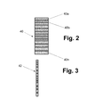
- FIG. 2 is a diametric sectional view of a polymer plate obtained by the method of the invention.
- FIG. 3 is a diametric sectional view of a track membrane produced by the method of the invention.
- FIGS. 4A and 4B are microphotographs of sections of treated samples obtained on a Multimode V Atomic Force Microscope (Veeco).
- the method of one or more embodiments of the invention is aimed at manufacturing track membranes.
- a track membrane is a thin polymer film with through pores which are formed by penetrating a special substance into and through the material of a polymer plate and then removing the traces of penetrated particles from the matrix material thus forming pores.
- the track membrane may find use in various fields of industry as conventional membrane filters for purification of liquid substances from solid contaminants. In view of low manufacturing cost and only a slight deviation of the holes from the rated diameter (within the limits of 10 to 20%), the track membrane of the invention may be advantageously used as a dialysis filter.
- a method of one or more embodiments of the invention comprises forming membrane with through openings by piercing a membrane matrix located in a tubular shell with particles of an oversaturated aqueous soluble solution of a water-soluble salt or salts contained in a high-speed jet generated by explosion of an explosive material detonated in the same shell.
- the obtained membrane is suitable for use as a filter for separating liquids from solid particles that may be contained in such liquids.
- the method of one or more embodiments of the invention comprises the steps of:
- a cartridge that is secured at the first end of the shell and contains a detonatable explosive material and a working substance in the form of at least one supersaturated solution of at least one water-soluble salt;
- the method further comprises the step of disconnecting the cover from the holder, removing the membrane matrix having residual water-soluble particles of the working substance from the cavity of the retainer, and treating the membrane matrix with water for dissolving the residual particles or washing them out from the membrane matrix and for forming a membrane with through openings.
- the polymer plate is sliced into thin pieces of a require thickness that can be used, e.g., as filter plates.
- the thin pieces again are subjected to a second water treatment for final rinse.
- the membrane matrix material is an organic polymer material such as polyolefin (polyethylene, polypropylene, etc.), polyvinylchloride, fluorinated polyolefin (polytetrafluoroethylene, polyvinylidene fluoride, etc.), polyamide, polycarbonate, polyester, polysulfone, etc.
- organic polymer material such as polyolefin (polyethylene, polypropylene, etc.), polyvinylchloride, fluorinated polyolefin (polytetrafluoroethylene, polyvinylidene fluoride, etc.), polyamide, polycarbonate, polyester, polysulfone, etc.
- the working substance may also contain at least one saturated solution of water soluble salts and may be selected from the group consisting of saturated aqueous solution of at least one water-soluble organic salt, a supersaturated aqueous solution of at least one water-soluble organic salt, a saturated aqueous solution of at least one water soluble inorganic salt, and a supersaturated aqueous solution of at least one water-soluble inorganic salt.
- the organic salts are selected from the group comprising tartrates, acetates, salicylates, benzoates of alkali metals, for example potassium tartrate, sodium acetate, sodium salicylate.
- the inorganic salts are selected from the group comprising halides of the alkali metals and alkaline earth metals, for example sodium chloride, sodium bromide, potassium fluoride, calcium chloride.
- the solid plate of the matrix polymer materials may have a total thickness in the range of 10 to 20 mm. After piercing with the particles the plate is sliced into track membranes having a thickness of 5 to 50 ⁇ m by means of a microtome.
- the through holes formed in the track membrane by the method of the invention may have diameters ranging from 80 nm to 100,000 nm.
- the actual diameters and the range of the diameters of the holes depend mainly on the velocity of the particles, diameter of the shell, and a distance from the cartridge with the explosive material and the particles to the membrane matrix material in the holder.
- the through holes produced in the track membrane by the method of the invention are oriented in the direction of the jet of particles and occupy from 10 to 20 vol. % of the membrane material volume.
- the explosion wave that has a detonating nature imparts to the particles of the working substance a velocity in the range of 3800 to 4200 m/sec.
- removal of the residual trace particles of the substance from the membrane may be carried out in the running flow of water.
- FIG. 1 is a vertical sectional view of the device.
- the device which as a whole is designated by reference numeral 20 contains a tubular shell 22 made, e.g., of a plastic material such as polyvinylchloride.
- the tubular shell 22 has open ends 22 a and 22 b .
- the device 20 also contains a cartridge 24 with the aforementioned detonatable explosive material 26 and the working substance 28 in the form of a saturated/supersaturated solution of at least one water-soluble salt.
- the cartridge is inserted into the open end 22 a of the tubular holder 22 .
- Reference numeral 29 designates a detonator that is used for detonation of the explosive material 26 .
- the device 20 contains a membrane holder 30 with an open-bottom cavity 30 a for receiving a membrane matrix 32 that can be inserted into the cavity 30 a of the holder 30 so that when the holder 30 is inserted into the shell 22 , a major part of the membrane surface remains exposed to the interior of the tubular shell.
- the membrane holder 30 is provided with a cover 33 attachable to the holder 30 , e.g., by fasteners, such as studs 35 a and 35 b shown in FIG. 1 , for covering the membrane matrix 32 .
- the holder 30 with the membrane matrix 32 and the cover 33 is freely inserted into the opposite end 22 b of the tubular shell 22 .
- the shell 22 with the holder 30 and the cartridge 24 is placed into an explosion-proof chamber 36 .
- the explosive material 26 when the explosive material 26 is detonated by the detonator 29 , this generates an explosion inside the shell 22 .
- the particles of the working material substance 28 that comprises the high-speed jet of the water-soluble salt, formed from the saturated/supersaturated aqueous solution of water soluble organic or inorganic salts will be directed toward the surface of the membrane matrix 32 exposed to the high-speed flow of the particles, in view of high kinetic velocity (3800 to 4200 m/sec) imparted to the particles of the working substance.
- some particles will deeply penetrate into the membrane matrix material and some particles will pierce the body of the membrane matrix 32 from its exposed side.
- the holder 30 together with the membrane matrix 32 and the cover 33 will be expelled from the shell 22 into the explosion-proof chamber 36 .
- the shell 22 and cartridge 24 will collapse.
- the cover 33 is then disconnected from the holder 30 , and the treated membrane matrix 32 is extracted from the holder 30 .
- the membrane matrix 32 will still contain residue of the water-soluble particles of the working substance 28 .
- the membrane matrix material 32 is then washed with water, whereby the residue of the water-soluble particles of the working substance 28 is dissolved or washed out from the membrane matrix leaving a plurality of small-diameter holes.
- a polymer plate 40 shown in FIG. 2 with a plurality of small holes 40 a , 40 b , . . . 40 n is obtained.
- the diameters of the holes may be selected within the range of 80 nm to 100,000 nm. However, deviations of the hole diameters from the rated value is insignificant and may be within the range of 10% to 20%.
- the solid plate 40 of the matrix polymer materials may have a total thickness in the range of 10 to 20 mm. After removal of the residue of the working substance, the solid plate 40 is sliced into track membranes having a thickness of 5 to 50 ⁇ m by means of a microtome. As a result, track membranes, one of which, i.e., a track membrane 42 is shown in FIG. 3 , are obtained.
- Samples of the track membranes produced by a method of an embodiment of the invention were observed under a Multimode V Atomic Force Microscope (Veeco), and micropictures were taken (see FIGS. 4A and 4B ).
- the pictures show sections of samples taken parallel to the diameter of the polymeric cylinder by means of microtome.
- the black dots in the photographs represent the pores of the sliced samples.
- Specimen 1 of a polymer plate produced by the method of an embodiment of the invention comprised a 15 mm-thick circular plate made from a shock-resistant polyethylene.
- the working substance comprised a supersaturated aqueous solution of potassium tartrate having concentration of 60% by weight.
- the test was conducted with the use of the device of the type described above and shown in FIG. 1 .
- Length of the shell 22 was 200 mm
- explosive material 26 was 25 g of ammonite #6 (79% w/w of ammonium nitrate and 21% w/w of TNT; density 0.8-0.9 g/cm3).
- the velocity of particles of potassium tartrate developed under the effect of the explosive wave and by flash evaporation of water was 3800 m/s.
- the results are shown in the microphotography presented by FIG. 4A , where the pores formed in the matrix material after washing out the residue of the potassium tartrate particles are seen as black spots.
- the rated diameter of the holes was 22 ⁇ m with deviations from the value of 22 ⁇ m in the range of 13%.
- Specimen 2 of a polymer plate produced by a method of an embodiment of the invention comprised a 15 mm-thick circular plate made from a polytetrafluoroethylene.
- the working substance comprised a 30% w/w aqueous solution of sodium chloride.
- the test was conducted with the use of the device of the type described above and shown in FIG. 1 .
- Length of the shell 22 was 200 mm
- explosive material 26 was 25 g of ammonite #6 (79% w/w of ammonium nitrate and 21% w/w of TNT; density 0.8-0.9 g/cm3).
- the velocity of particles of sodium chloride developed under the effect of the explosive wave and by flash evaporation of water was 4200 m/s.
- the results are shown in the microphotography presented by FIG. 4B , where the pores formed in the matrix material after washing out the residue of the sodium chloride particles are seen as black spots.
- the rated diameter of the holes was 25 ⁇ m with deviations from the value of 25 ⁇ m in the range of 19%.
Abstract
Description
Claims (18)
Priority Applications (1)
| Application Number | Priority Date | Filing Date | Title |
|---|---|---|---|
| US13/442,799 US8980148B2 (en) | 2012-04-09 | 2012-04-09 | Method of manufacturing a track membrane |
Applications Claiming Priority (1)
| Application Number | Priority Date | Filing Date | Title |
|---|---|---|---|
| US13/442,799 US8980148B2 (en) | 2012-04-09 | 2012-04-09 | Method of manufacturing a track membrane |
Publications (2)
| Publication Number | Publication Date |
|---|---|
| US20130264737A1 US20130264737A1 (en) | 2013-10-10 |
| US8980148B2 true US8980148B2 (en) | 2015-03-17 |
Family
ID=49291670
Family Applications (1)
| Application Number | Title | Priority Date | Filing Date |
|---|---|---|---|
| US13/442,799 Expired - Fee Related US8980148B2 (en) | 2012-04-09 | 2012-04-09 | Method of manufacturing a track membrane |
Country Status (1)
| Country | Link |
|---|---|
| US (1) | US8980148B2 (en) |
Cited By (2)
| Publication number | Priority date | Publication date | Assignee | Title |
|---|---|---|---|---|
| RU2637230C1 (en) * | 2016-10-26 | 2017-12-01 | Федеральное государственное автономное образовательное учреждение высшего образования "Национальный исследовательский Томский политехнический университет" | Method of forming polymeric track membrane with cavity of given curvature and device for its implementation |
| RU2687921C1 (en) * | 2018-05-03 | 2019-05-16 | Закрытое Акционерное Общество "Владисарт" | Filtering element for separation and concentration of liquid media |
Citations (9)
| Publication number | Priority date | Publication date | Assignee | Title |
|---|---|---|---|---|
| US3303085A (en) | 1962-02-28 | 1967-02-07 | Gen Electric | Molecular sieves and methods for producing same |
| US3770532A (en) | 1971-02-16 | 1973-11-06 | Gen Electric | Porous bodies and method of making |
| US3802972A (en) | 1968-06-27 | 1974-04-09 | Gen Electric | Process for making cylindrical holes in a sheet material |
| US4960430A (en) | 1987-05-13 | 1990-10-02 | Veb Greika Greiz Weberei Und Veredlung | Method for manufacturing of mat and rough, laminar, ribbon-shaped or fibrous polymeric products with a stream of particles |
| US5330790A (en) | 1992-02-07 | 1994-07-19 | Calkins Noel C | Impact implantation of particulate material into polymer surfaces |
| US7001501B2 (en) | 2000-09-08 | 2006-02-21 | Gesellschaft für Schwerionenforschung mbH | Method for etching at least one ion track to a pore in a membrane and electrolyte cell for preparing the membrane |
| US7597815B2 (en) | 2003-05-29 | 2009-10-06 | Dressel Pte. Ltd. | Process for producing a porous track membrane |
| US7897204B2 (en) | 2009-01-29 | 2011-03-01 | Nanotech Industries, Inc. | Method of strengthening tool material by penetration of reinforcing particles |
| RU2425912C2 (en) | 2009-08-04 | 2011-08-10 | Институт гидродинамики им. М.А. Лаврентьева Сибирского отделения Российской академии наук (ИГиЛ СО РАН) | Procedure for metallisation of part of polymer material by detonation sputtering |
-
2012
- 2012-04-09 US US13/442,799 patent/US8980148B2/en not_active Expired - Fee Related
Patent Citations (9)
| Publication number | Priority date | Publication date | Assignee | Title |
|---|---|---|---|---|
| US3303085A (en) | 1962-02-28 | 1967-02-07 | Gen Electric | Molecular sieves and methods for producing same |
| US3802972A (en) | 1968-06-27 | 1974-04-09 | Gen Electric | Process for making cylindrical holes in a sheet material |
| US3770532A (en) | 1971-02-16 | 1973-11-06 | Gen Electric | Porous bodies and method of making |
| US4960430A (en) | 1987-05-13 | 1990-10-02 | Veb Greika Greiz Weberei Und Veredlung | Method for manufacturing of mat and rough, laminar, ribbon-shaped or fibrous polymeric products with a stream of particles |
| US5330790A (en) | 1992-02-07 | 1994-07-19 | Calkins Noel C | Impact implantation of particulate material into polymer surfaces |
| US7001501B2 (en) | 2000-09-08 | 2006-02-21 | Gesellschaft für Schwerionenforschung mbH | Method for etching at least one ion track to a pore in a membrane and electrolyte cell for preparing the membrane |
| US7597815B2 (en) | 2003-05-29 | 2009-10-06 | Dressel Pte. Ltd. | Process for producing a porous track membrane |
| US7897204B2 (en) | 2009-01-29 | 2011-03-01 | Nanotech Industries, Inc. | Method of strengthening tool material by penetration of reinforcing particles |
| RU2425912C2 (en) | 2009-08-04 | 2011-08-10 | Институт гидродинамики им. М.А. Лаврентьева Сибирского отделения Российской академии наук (ИГиЛ СО РАН) | Procedure for metallisation of part of polymer material by detonation sputtering |
Cited By (2)
| Publication number | Priority date | Publication date | Assignee | Title |
|---|---|---|---|---|
| RU2637230C1 (en) * | 2016-10-26 | 2017-12-01 | Федеральное государственное автономное образовательное учреждение высшего образования "Национальный исследовательский Томский политехнический университет" | Method of forming polymeric track membrane with cavity of given curvature and device for its implementation |
| RU2687921C1 (en) * | 2018-05-03 | 2019-05-16 | Закрытое Акционерное Общество "Владисарт" | Filtering element for separation and concentration of liquid media |
Also Published As
| Publication number | Publication date |
|---|---|
| US20130264737A1 (en) | 2013-10-10 |
Similar Documents
| Publication | Publication Date | Title |
|---|---|---|
| Sullivan et al. | Controlling material reactivity using architecture | |
| Liu et al. | Ultralight free-standing reduced graphene oxide membranes for oil-in-water emulsion separation | |
| US7497951B2 (en) | Composite semipermeable membrane, production process thereof, and element, fluid separation equipment and method for water treatment using the same | |
| US8980148B2 (en) | Method of manufacturing a track membrane | |
| Scott | The role of salt in whitecap persistence | |
| EP3616778B1 (en) | Semipermeable composite membrane and method for producing same | |
| Cui et al. | Optimization of novel composite membranes for water and mineral recovery by vacuum membrane distillation | |
| KR20170071502A (en) | Forward osmosis process for concentration of lithium containing solutions | |
| Xue et al. | All-polymer and self-roughened superhydrophobic PVDF fibrous membranes for stably concentrating seawater by membrane distillation | |
| Awolayo et al. | Impact of multi-ion interactions on oil mobilization by smart waterflooding in carbonate reservoirs | |
| Zahedi et al. | Separation study of Mg+ 2 from seawater and RO brine through a facilitated bulk liquid membrane transport using 18-Crown-6 | |
| Figovsky et al. | Production of polymer nanomembranes by super deep penetration method | |
| Issar | The rate of flushing as a major factor in determining the chemistry of water in fossil aquifers in southern Israel | |
| Omichi et al. | Application of ion beams to synthesis of environmentally responsive track membranes | |
| Figovsky et al. | The production of polymer tracking membranes by super deep penetration method | |
| Raval et al. | A novel thin film composite reverse osmosis membrane modified by ionic liquid | |
| JP2687142B2 (en) | Method for manufacturing porous polyimide film | |
| CN105233700A (en) | Manufacturing method for nuclear track etched membrane with single taper micropore | |
| Kulshrestha et al. | Swift heavy ion (SHI) irradiated polymer blend membranes for hydrogen permeation | |
| Zhang et al. | Smart Janus titanium mesh used as a diode for both liquid droplet and air bubble transport | |
| Komaki et al. | Observation of nuclear track development in polyvinylidene fluoride with several etchants | |
| Фиговский | ADVANCED METHODS OF NANOMEMBRANES’PRODUCING | |
| JP6214091B2 (en) | Method for producing water containing nanobubbles | |
| JP2006504746A5 (en) | ||
| Eliasson et al. | Dynamics of whistler spheromaks in magnetized plasmas |
Legal Events
| Date | Code | Title | Description |
|---|---|---|---|
| AS | Assignment |
Owner name: NANOTECH INDUSTRIES, INC., CALIFORNIA Free format text: ASSIGNMENT OF ASSIGNORS INTEREST;ASSIGNORS:FIGOVSKY, OLEG;GOTLIB, ELENA;PASHIN, DMITRY;AND OTHERS;REEL/FRAME:028015/0711 Effective date: 20120405 Owner name: POLYMATE, LTD., ISRAEL Free format text: ASSIGNMENT OF ASSIGNORS INTEREST;ASSIGNORS:FIGOVSKY, OLEG;GOTLIB, ELENA;PASHIN, DMITRY;AND OTHERS;REEL/FRAME:028015/0711 Effective date: 20120405 |
|
| STCF | Information on status: patent grant |
Free format text: PATENTED CASE |
|
| FEPP | Fee payment procedure |
Free format text: MAINTENANCE FEE REMINDER MAILED (ORIGINAL EVENT CODE: REM.); ENTITY STATUS OF PATENT OWNER: SMALL ENTITY |
|
| LAPS | Lapse for failure to pay maintenance fees |
Free format text: PATENT EXPIRED FOR FAILURE TO PAY MAINTENANCE FEES (ORIGINAL EVENT CODE: EXP.); ENTITY STATUS OF PATENT OWNER: SMALL ENTITY |
|
| STCH | Information on status: patent discontinuation |
Free format text: PATENT EXPIRED DUE TO NONPAYMENT OF MAINTENANCE FEES UNDER 37 CFR 1.362 |
|
| FP | Lapsed due to failure to pay maintenance fee |
Effective date: 20190317 |
|
| AS | Assignment |
Owner name: NANOTECH INDUSTRIES INC., CALIFORNIA Free format text: ASSIGNMENT OF ASSIGNORS INTEREST;ASSIGNOR:POLYMATE LTD.;REEL/FRAME:050646/0019 Effective date: 20191007 |
|
| AS | Assignment |
Owner name: LIFSCHITZ, YAKOV MARK, CALIFORNIA Free format text: ASSIGNMENT OF ASSIGNORS INTEREST;ASSIGNOR:NELLIS, DARIN;REEL/FRAME:050851/0276 Effective date: 20191029 |