US8970795B2 - Sliding panels system for hiding a flat screen TV - Google Patents
Sliding panels system for hiding a flat screen TV Download PDFInfo
- Publication number
- US8970795B2 US8970795B2 US13/871,387 US201313871387A US8970795B2 US 8970795 B2 US8970795 B2 US 8970795B2 US 201313871387 A US201313871387 A US 201313871387A US 8970795 B2 US8970795 B2 US 8970795B2
- Authority
- US
- United States
- Prior art keywords
- members
- panel
- assembly
- assemblies
- extendable
- Prior art date
- Legal status (The legal status is an assumption and is not a legal conclusion. Google has not performed a legal analysis and makes no representation as to the accuracy of the status listed.)
- Expired - Fee Related, expires
Links
Images


Classifications
-
- A—HUMAN NECESSITIES
- A47—FURNITURE; DOMESTIC ARTICLES OR APPLIANCES; COFFEE MILLS; SPICE MILLS; SUCTION CLEANERS IN GENERAL
- A47B—TABLES; DESKS; OFFICE FURNITURE; CABINETS; DRAWERS; GENERAL DETAILS OF FURNITURE
- A47B81/00—Cabinets or racks specially adapted for other particular purposes, e.g. for storing guns or skis
- A47B81/06—Furniture aspects of radio, television, gramophone, or record cabinets
-
- F—MECHANICAL ENGINEERING; LIGHTING; HEATING; WEAPONS; BLASTING
- F16—ENGINEERING ELEMENTS AND UNITS; GENERAL MEASURES FOR PRODUCING AND MAINTAINING EFFECTIVE FUNCTIONING OF MACHINES OR INSTALLATIONS; THERMAL INSULATION IN GENERAL
- F16M—FRAMES, CASINGS OR BEDS OF ENGINES, MACHINES OR APPARATUS, NOT SPECIFIC TO ENGINES, MACHINES OR APPARATUS PROVIDED FOR ELSEWHERE; STANDS; SUPPORTS
- F16M13/00—Other supports for positioning apparatus or articles; Means for steadying hand-held apparatus or articles
- F16M13/02—Other supports for positioning apparatus or articles; Means for steadying hand-held apparatus or articles for supporting on, or attaching to, an object, e.g. tree, gate, window-frame, cycle
-
- A—HUMAN NECESSITIES
- A47—FURNITURE; DOMESTIC ARTICLES OR APPLIANCES; COFFEE MILLS; SPICE MILLS; SUCTION CLEANERS IN GENERAL
- A47B—TABLES; DESKS; OFFICE FURNITURE; CABINETS; DRAWERS; GENERAL DETAILS OF FURNITURE
- A47B81/00—Cabinets or racks specially adapted for other particular purposes, e.g. for storing guns or skis
- A47B81/06—Furniture aspects of radio, television, gramophone, or record cabinets
- A47B81/061—Furniture aspects of radio, television, gramophone, or record cabinets the device supports being adjustable
- A47B81/062—Furniture aspects of radio, television, gramophone, or record cabinets the device supports being adjustable horizontally
-
- F—MECHANICAL ENGINEERING; LIGHTING; HEATING; WEAPONS; BLASTING
- F16—ENGINEERING ELEMENTS AND UNITS; GENERAL MEASURES FOR PRODUCING AND MAINTAINING EFFECTIVE FUNCTIONING OF MACHINES OR INSTALLATIONS; THERMAL INSULATION IN GENERAL
- F16M—FRAMES, CASINGS OR BEDS OF ENGINES, MACHINES OR APPARATUS, NOT SPECIFIC TO ENGINES, MACHINES OR APPARATUS PROVIDED FOR ELSEWHERE; STANDS; SUPPORTS
- F16M11/00—Stands or trestles as supports for apparatus or articles placed thereon Stands for scientific apparatus such as gravitational force meters
- F16M11/02—Heads
- F16M11/04—Means for attachment of apparatus; Means allowing adjustment of the apparatus relatively to the stand
- F16M11/043—Allowing translations
- F16M11/045—Allowing translations adapted to left-right translation movement
-
- F—MECHANICAL ENGINEERING; LIGHTING; HEATING; WEAPONS; BLASTING
- F16—ENGINEERING ELEMENTS AND UNITS; GENERAL MEASURES FOR PRODUCING AND MAINTAINING EFFECTIVE FUNCTIONING OF MACHINES OR INSTALLATIONS; THERMAL INSULATION IN GENERAL
- F16M—FRAMES, CASINGS OR BEDS OF ENGINES, MACHINES OR APPARATUS, NOT SPECIFIC TO ENGINES, MACHINES OR APPARATUS PROVIDED FOR ELSEWHERE; STANDS; SUPPORTS
- F16M11/00—Stands or trestles as supports for apparatus or articles placed thereon Stands for scientific apparatus such as gravitational force meters
- F16M11/02—Heads
- F16M11/18—Heads with mechanism for moving the apparatus relatively to the stand
Definitions
- the present invention relates generally to sliding panels but more particularly to sliding panels system for hiding a flat screen TV.
- the invention consists of a sliding panels system for hiding a flat screen television having a frame structure consisting of a wall attachment panel adapted to be securely attached to a wall member, a pair of post members spaced from one another and attached to the wall attachment panel, Upper and lower rail assemblies are extendable, spaced apart, and parallel to one another and attached between the post members.
- a first side support bracket assembly connected between the upper and lower rail assemblies on first ends thereof, and a second side support bracket assembly connected between the upper and lower rail assemblies on second ends thereof, such that the space between the first and second support bracket assemblies can be adjusted by the extendable upper and lower rail assemblies; and first and second panel members respectively attached to the first and second support bracket assemblies, such that the first and second panel members can be moved between an open position wherein the panel members are spaced apart and a closed position wherein the panel members are abutting one another.
- the sliding panels system is preferably comprised of a looped cable forming an upper loop portion and a lower loop portion, the upper loop portion attached at one point to a first portion of the extendable upper rail assembly via a first connector, and the lower loop portion attached at a second point to a second portion of the extendable upper rail assembly that is movable from the first portion of the upper rail assembly via a second connector.
- the looped cable is rotated in one direction, the extendable upper and lower rail members extend outwards and move the first and second panel members away from one another, and when the looped cable is rotated in the opposite direction, the extendable upper and lower rail members retract inwards and move the first and second panel members towards one another.
- the sliding panels system has the extendable upper rail assembly include an elongated bracket member extending a length upon the upper rail assembly that is greater than a maximum width of the space between the first and second panel members when the upper rail assembly is fully extended; and wherein the elongated bracket member includes a pulley member on each opposite end portion thereof, such that the looped cable is wrapped around both pulleys forming a taught elongated loop.
- the sliding panels system has the upper rail assembly bracket member include an electric motor assembly located on an end portion thereof adjacent one of the pulley members>
- the electric motor assembly includes an electric motor, a motor wheel, a motor cable, and a transmission adapted to allow the motor wheel to turn in forward and reverse directions, wherein the motor cable is adapted to be connected between the motor wheel and the one of the pulley members, such that the electric motor assembly is adapted to mechanically open and close the first and second panel members.
- the sliding panels system has the upper and lower rail assemblies each formed from two respective telescoping inner and outer rail members, such that the first connector is connected to a first telescoping part of the upper rail assembly, and the second connector is connected to a second telescoping part of the upper rail assembly.
- the sliding panels system has the sliding panels are opened and closed by way of a remote control device.
- the sliding panels work in combination with a flat screen television.
- FIGS. 1 a - d Isometric rear view and isometric detail views of the invention and its main components.
- FIG. 2 Isometric front view of the invention with panels closed.
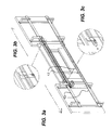
- FIGS. 3 a - c Isometric rear view with panels opened and isometric details of components.
- FIGS. 4 a - b Top and front views with panels closed.
- FIGS. 5 a - b Top and front views with panels opened.
- FIG. 6 Rear view of the invention.
- FIG. 7 Side view of the invention.
- a sliding panels system ( 10 ) for hiding a flat screen TV ( 12 ) has a frame structure comprised of a wall attachment panel ( 15 ) attached to a wall ( 11 ) on one side and connected to a pair of generally vertical post members ( 26 ) on the other side.
- the vertical post members ( 26 ) hold upper and lower rail assemblies ( 14 , 14 ′) perpendicularly therefrom.
- the rail assemblies ( 14 , 14 ′) are telescopic in nature, meaning that there is an inner rail members ( 13 ) sliding out from outer rail members ( 17 ).
- the rail assemblies are connected by way of support brackets ( 18 ) to panels ( 28 ).
- a looped cable ( 20 ) is what pulls on the rail assemblies ( 14 , 14 ′) either apart or together so as to move the panels ( 28 ).
- the cable ( 20 ) is arranged in a “clothes line” fashion with a first connector ( 30 ) attached to the part of the looped cable ( 20 ) that runs top part of the cable ( 20 ) and a second connector ( 30 ′) attached to the part of the cable ( 20 ) running on the bottom.
- the cable ( 20 ) is part of an assembly comprised of pulleys ( 22 ) and at least one electric motor assembly ( 24 ).
- the motor assembly ( 24 ) is comprised of an electric motor (not shown), a transmission (not shown) and a motor wheel ( 32 ) as is known in the art and held in place by way of a motor assembly bracket ( 25 ).
- a remote control device comprised of a remote unit ( 30 ) and an an associated signal receiver (not shown) control the opening and closing of the sliding panels system ( 10 ).
- a wall switch (not shown) can also control the opening and closing.
Abstract
A sliding panels system for hiding a flat screen television, has a wall attachment panel, a pair of post members spaced from one another and attached to the wall attachment panel. Extendable upper and lower rail assemblies attached between the post members. A first side support bracket assembly connected between the upper and lower rail assemblies on first ends thereof, and a second side support bracket assembly connected between the upper and lower rail assemblies on second ends thereof, such that the space between the first and second support bracket assemblies can be adjusted by the extendable upper and lower rail assemblies; and first and second panel members respectively attached to the first and second support bracket assemblies, such that the first and second panel members can be moved between an open and a closed position.
Description
This application claims priority based on request GB1209048.6 filed May 25, 2012
The present invention relates generally to sliding panels but more particularly to sliding panels system for hiding a flat screen TV.
Flat screen TVs are quite common but their huge sizes are not always appreciated in some home decor. There has to be a practical way of hiding the screens. There does not seem to be readily available screen hiding devices in the marketplace.
In view of the foregoing disadvantages inherent in the known devices now present in the prior art, the present invention, which will be described subsequently in greater detail, is to provide objects and advantages which are:
To provide for a convenient means for hiding a large flat screen TV.
In order to do so, the invention consists of a sliding panels system for hiding a flat screen television having a frame structure consisting of a wall attachment panel adapted to be securely attached to a wall member, a pair of post members spaced from one another and attached to the wall attachment panel, Upper and lower rail assemblies are extendable, spaced apart, and parallel to one another and attached between the post members. A first side support bracket assembly connected between the upper and lower rail assemblies on first ends thereof, and a second side support bracket assembly connected between the upper and lower rail assemblies on second ends thereof, such that the space between the first and second support bracket assemblies can be adjusted by the extendable upper and lower rail assemblies; and first and second panel members respectively attached to the first and second support bracket assemblies, such that the first and second panel members can be moved between an open position wherein the panel members are spaced apart and a closed position wherein the panel members are abutting one another.
The sliding panels system is preferably comprised of a looped cable forming an upper loop portion and a lower loop portion, the upper loop portion attached at one point to a first portion of the extendable upper rail assembly via a first connector, and the lower loop portion attached at a second point to a second portion of the extendable upper rail assembly that is movable from the first portion of the upper rail assembly via a second connector. When the looped cable is rotated in one direction, the extendable upper and lower rail members extend outwards and move the first and second panel members away from one another, and when the looped cable is rotated in the opposite direction, the extendable upper and lower rail members retract inwards and move the first and second panel members towards one another.
The sliding panels system has the extendable upper rail assembly include an elongated bracket member extending a length upon the upper rail assembly that is greater than a maximum width of the space between the first and second panel members when the upper rail assembly is fully extended; and wherein the elongated bracket member includes a pulley member on each opposite end portion thereof, such that the looped cable is wrapped around both pulleys forming a taught elongated loop.
In a preferred embodiment, the sliding panels system has the upper rail assembly bracket member include an electric motor assembly located on an end portion thereof adjacent one of the pulley members> The electric motor assembly includes an electric motor, a motor wheel, a motor cable, and a transmission adapted to allow the motor wheel to turn in forward and reverse directions, wherein the motor cable is adapted to be connected between the motor wheel and the one of the pulley members, such that the electric motor assembly is adapted to mechanically open and close the first and second panel members.
The sliding panels system has the upper and lower rail assemblies each formed from two respective telescoping inner and outer rail members, such that the first connector is connected to a first telescoping part of the upper rail assembly, and the second connector is connected to a second telescoping part of the upper rail assembly.
In a preferred embodiment, the sliding panels system has the sliding panels are opened and closed by way of a remote control device.
The sliding panels work in combination with a flat screen television.
There has thus been outlined, rather broadly, the more important features of the invention in order that the detailed description thereof that follows may be better understood, and in order that the present contribution to the art may be better appreciated. There are additional features of the invention that will be described hereinafter and which will form the subject matter of the claims appended hereto.
In this respect, before explaining at least one embodiment of the invention in detail, it is to be understood that the invention is not limited in its application to the details of construction and to the arrangements of the components set forth in the following description or illustrated in the drawings. The invention is capable of other embodiments and of being practiced and carried out in various ways. Also, it is to be understood that the phraseology and terminology employed herein are for the purpose of description and should not be regarded as limiting.
As such, those skilled in the art will appreciate that the conception, upon which this disclosure is based, may readily be utilized as a basis for the designing of other structures, methods and systems for carrying out the several purposes of the present invention. It is important, therefore, that the claims be regarded as including such equivalent constructions insofar as they do not depart from the spirit and scope of the present invention.
These together with other objects of the invention, along with the various features of novelty which characterize the invention, are pointed out with particularity in the claims annexed to and forming a part of this disclosure. For a better understanding of the invention, its operating advantages and the specific objects attained by its uses, reference should be made to the accompanying drawings and descriptive matter which contains illustrated preferred embodiments of the invention.
A sliding panels system (10) for hiding a flat screen TV (12) has a frame structure comprised of a wall attachment panel (15) attached to a wall (11) on one side and connected to a pair of generally vertical post members (26) on the other side. The vertical post members (26) hold upper and lower rail assemblies (14, 14′) perpendicularly therefrom. The rail assemblies (14, 14′) are telescopic in nature, meaning that there is an inner rail members (13) sliding out from outer rail members (17). The rail assemblies are connected by way of support brackets (18) to panels (28).
A looped cable (20) is what pulls on the rail assemblies (14, 14′) either apart or together so as to move the panels (28). The cable (20) is arranged in a “clothes line” fashion with a first connector (30) attached to the part of the looped cable (20) that runs top part of the cable (20) and a second connector (30′) attached to the part of the cable (20) running on the bottom. The cable (20) is part of an assembly comprised of pulleys (22) and at least one electric motor assembly (24).
The motor assembly (24) is comprised of an electric motor (not shown), a transmission (not shown) and a motor wheel (32) as is known in the art and held in place by way of a motor assembly bracket (25).
Typically, a remote control device comprised of a remote unit (30) and an an associated signal receiver (not shown) control the opening and closing of the sliding panels system (10). Alternatively, or a wall switch (not shown) can also control the opening and closing.
As to a further discussion of the manner of usage and operation of the present invention, the same should be apparent from the above description. Accordingly, no further discussion relating to the manner of usage and operation will be provided.
With respect to the above description then, it is to be realized that the optimum dimensional relationships for the parts of the invention, to include variations in size, materials, shape, form, function and manner of operation, assembly and use, are deemed readily apparent and obvious to one skilled in the art, and all equivalent relationships to those illustrated in the drawings and described in the specification are intended to be encompassed by the present invention.
Therefore, the foregoing is considered as illustrative only of the principles of the invention. Further, since numerous modifications and changes will readily occur to those skilled in the art, it is not desired to limit the invention to the exact construction and operation shown and described, and accordingly, all suitable modifications and equivalents may be resorted to, falling within the scope of the invention.
Claims (9)
1. A sliding panel system for hiding a flat screen television, said sliding panel system comprising a frame structure consisting of a wall attachment panel adapted to be securely attached to a wall member, a pair of post members spaced from one another and attached to said wall attachment panel, upper and lower rail assemblies that are extendable, spaced apart, and parallel to one another and attached between said post members, a first side support bracket assembly connected between said upper and lower rail assemblies on first ends thereof, and a second side support bracket assembly connected between said upper and lower rail assemblies on second ends thereof, such that a space between said first and second support bracket assemblies can be adjusted by said extendable upper and lower rail assemblies; and first and second panel members respectively attached to said first and second support bracket assemblies, such that said first and second panel members can be moved between an open position wherein said panel members are spaced apart and a dosed position wherein said panel members are abutting one another; a looped cable forming an upper loop portion and a lower loop portion, said upper loop portion attached at one point to a first portion of said extendable upper rail assembly via a first connector, and said lower loop portion attached at a second point to a second portion of said extendable upper rail assembly that is movable from said first portion of said upper rail assembly via a second connector; such that when said looped cable is rotated in one direction, said extendable upper and lower rail members extend outwards and move said first and second panel members away from one another, and when said looped cable is rotated in the opposite direction, said extendable upper and lower rail members retract inwards and move said first and second panel members towards one another, said extendable upper rail assembly includes an elongated bracket member extending a length upon said upper rail assembly that is greater than a maximum width of a space between said first and second panel members when said upper rail assembly is fully extended; and wherein said elongated bracket member includes a pulley member on each opposite end portion thereof, such that said looped cable is wrapped around both pulleys forming a taught elongated loop.
2. The sliding panels system of claim 1 , wherein said upper rail assembly bracket member includes an electric motor assembly located on an end portion thereof adjacent one of said pulley members, said electric motor assembly includes an electric motor, a motor wheel, a motor cable, and a transmission adapted to allow said motor wheel to turn in forward and reverse directions, wherein said motor cable is adapted to be connected between said motor wheel and said one of said pulley members, such that said electric motor assembly is adapted to mechanically open and close said first and second panel members.
3. The sliding panels system of claim 1 , wherein said upper and lower rail assemblies are each formed from two respective telescoping inner and outer rail members, such that said first connector is connected to a first telescoping part of said upper rail assembly, and said second connector is connected to a second telescoping part of said upper rail assembly.
4. The sliding panels system of claim 1 wherein said sliding panels are opened and closed by way of a remote control device.
5. A combination of a flat screen television and a sliding panel system for hiding said flat screen television, said combination comprises said flat screen television, and said sliding panel system configured to hide said television set and comprising a frame structure consisting of a wall attachment panel adapted to be securely attached to a wall member, a pair of post members spaced from one another and attached to said wall attachment panel, upper and lower rail assemblies that are extendable, spaced apart, and parallel to one another and attached between said post members, a first side support bracket assembly connected between said upper and lower rail assemblies on first ends thereof, and a second side support bracket assembly connected between said upper and lower rail assemblies on second ends thereof, such that a space between said first and second support bracket assemblies can be adjusted by said extendable upper and lower rail assemblies; and first and second panel members respectively attached to said first and second support bracket assemblies, such that said first and second panel members can be moved between an open position wherein said panel members are spaced apart and a closed position wherein said panel members are abutting one another; a looped cable forming an upper loop portion and a lower loop portion, said upper loop portion attached at one point to a first portion of said extendable upper rail assembly via a first connector, and said lower loop portion attached at a second point to a second portion of said extendable upper rail assembly that is movable from said first portion of said upper rail assembly via a second connector; such that when said looped cable is rotated in one direction, said extendable upper and lower rail members extend outwards and move said first and second panel members away from one another, and when said looped cable is rotated in the opposite direction, said extendable upper and lower rail members retract inwards and move said first and second panel members towards one another; said extendable upper rail assembly includes an elongated bracket member extending a length upon said upper rail assembly that is greater than a maximum width of a space between said first and second panel members when said upper rail assembly is fully extended; and wherein said elongated bracket member includes a pulley member on each opposite end portion thereof, such that said looped cable is wrapped around both pulleys forming a taught elongated loop.
6. The sliding panels system of claim 5 , wherein said upper rail assembly bracket member includes an electric motor assembly located on an end portion thereof adjacent one of said pulley members, said electric motor assembly includes an electric motor, a motor wheel, a motor cable, and a transmission adapted to allow said motor wheel to turn in forward and reverse directions, wherein said motor cable is adapted to be connected between said motor wheel and said one of said pulley members, such that said electric motor assembly is adapted to mechanically open and close said first and second panel members.
7. The sliding panels system of claim 5 , wherein said upper and lower rail assemblies are each formed from two respective telescoping inner and outer rail members, such that said first connector is connected to a first telescoping part of said upper rail assembly, and said second connector is connected to a second telescoping part of said upper rail assembly.
8. The sliding panels system of claim 5 , wherein said flat screen television is configured to fit between said upper and lower rail assemblies and said panel members.
9. The sliding system of claim 5 wherein said sliding panels are opened and closed by a remote control device.
Priority Applications (1)
| Application Number | Priority Date | Filing Date | Title |
|---|---|---|---|
| US13/871,387 US8970795B2 (en) | 2013-04-26 | 2013-04-26 | Sliding panels system for hiding a flat screen TV |
Applications Claiming Priority (1)
| Application Number | Priority Date | Filing Date | Title |
|---|---|---|---|
| US13/871,387 US8970795B2 (en) | 2013-04-26 | 2013-04-26 | Sliding panels system for hiding a flat screen TV |
Publications (2)
| Publication Number | Publication Date |
|---|---|
| US20140319978A1 US20140319978A1 (en) | 2014-10-30 |
| US8970795B2 true US8970795B2 (en) | 2015-03-03 |
Family
ID=51788677
Family Applications (1)
| Application Number | Title | Priority Date | Filing Date |
|---|---|---|---|
| US13/871,387 Expired - Fee Related US8970795B2 (en) | 2013-04-26 | 2013-04-26 | Sliding panels system for hiding a flat screen TV |
Country Status (1)
| Country | Link |
|---|---|
| US (1) | US8970795B2 (en) |
Cited By (4)
| Publication number | Priority date | Publication date | Assignee | Title |
|---|---|---|---|---|
| US10874028B2 (en) * | 2018-08-09 | 2020-12-22 | Lg Electronics Inc. | Smart wall |
| US11000126B1 (en) * | 2019-11-21 | 2021-05-11 | Lg Electronics Inc. | Smart wall |
| US11033107B2 (en) * | 2019-07-16 | 2021-06-15 | Francis Douglas Warren | Tilting mounting apparatus |
| USD979095S1 (en) * | 2020-07-22 | 2023-02-21 | Lg Electronics Inc. | Indoor wall with builtin home appliances |
Families Citing this family (10)
| Publication number | Priority date | Publication date | Assignee | Title |
|---|---|---|---|---|
| EP3091528B1 (en) * | 2015-05-05 | 2020-10-07 | Harman Professional Denmark ApS | Support frame for video wall |
| CN105221919B (en) * | 2015-10-27 | 2017-12-05 | 苏州罗普斯金铝业股份有限公司 | A kind of aluminium alloy extrusions framework |
| CN105443931B (en) * | 2015-12-30 | 2018-05-22 | 天津科岸仪器有限公司 | A kind of length-adjustable optical table instrument support |
| CN106855174B (en) * | 2016-12-08 | 2019-05-10 | 广州视源电子科技股份有限公司 | Show equipment and its mounting device |
| CN107084305B (en) * | 2017-01-24 | 2019-03-15 | 江西鑫彩晨光电科技有限公司 | A kind of wall-mounted display screen device |
| CN110863744A (en) * | 2018-08-28 | 2020-03-06 | 唐肖近 | Full-open glass window with built-in curtain |
| USD970472S1 (en) * | 2019-11-08 | 2022-11-22 | Lg Electronics Inc. | Door for an indoor wall with built-in home appliances |
| USD970473S1 (en) * | 2019-11-08 | 2022-11-22 | Lg Electronics Inc. | Door for an indoor wall with built-in home appliances |
| USD970470S1 (en) * | 2019-11-08 | 2022-11-22 | Lg Electronics Inc. | Door for an indoor wall with built-in home appliances |
| USD970471S1 (en) * | 2019-11-08 | 2022-11-22 | Lg Electronics Inc. | Door for an indoor wall with built-in home appliances |
Citations (43)
| Publication number | Priority date | Publication date | Assignee | Title |
|---|---|---|---|---|
| US736357A (en) * | 1903-01-03 | 1903-08-18 | Harry Brousseau | Hatch. |
| US1857368A (en) | 1930-05-06 | 1932-05-10 | John E Flynn | Curtain device |
| US2235380A (en) * | 1938-02-17 | 1941-03-18 | Westinghouse Elec Elevator Co | Elevator door operator |
| US2547447A (en) | 1942-03-18 | 1951-04-03 | Hartford Nat Bank & Trust Co | Apparatus for stereophonic sound reproduction |
| US2905463A (en) * | 1956-01-06 | 1959-09-22 | Toledo Scale Corp | Elevator door carrying mechanism |
| US3456995A (en) * | 1967-04-11 | 1969-07-22 | Gen Electric | Slide-in cabinet door |
| US4050191A (en) * | 1974-10-21 | 1977-09-27 | Yoshida Kogyo K.K. | Knockdown apparatus for supporting and driving overhung doors |
| US4910916A (en) * | 1987-07-23 | 1990-03-27 | Julius Blum Gesellschaft M.B.H. | Sliding door fitting |
| US4935819A (en) | 1988-12-22 | 1990-06-19 | Zenith Electronic Corporation | Picture-width-adaptable television receiver |
| US5138462A (en) | 1988-01-27 | 1992-08-11 | Bang & Olufsen A/S | TV-set having screen covering means |
| US5264765A (en) | 1992-03-27 | 1993-11-23 | Pecorino Philip A | Video display screen cover |
| US5711112A (en) * | 1996-09-03 | 1998-01-27 | Otis Elevator Company | Double-drive automatic sliding door operator |
| US6073375A (en) * | 1997-06-18 | 2000-06-13 | Fant; Patrick J. | Advertising display system for sliding panel doors |
| US6095623A (en) * | 1998-11-10 | 2000-08-01 | Sony Corporation | Three pillar construction stand |
| US6152549A (en) * | 1998-11-10 | 2000-11-28 | Sony Corporation | Frameless sliding door system for a television cabinet stand |
| US20020084727A1 (en) * | 2000-11-13 | 2002-07-04 | Miller Joseph E. | Armoire or entertainment center |
| US6480243B2 (en) * | 1998-06-18 | 2002-11-12 | Sony Corporation | Installation structure for panel-type display device |
| US20030201372A1 (en) * | 2002-04-26 | 2003-10-30 | Leonard Dozier | Mounting device for a flat screen display panel |
| US20040135476A1 (en) * | 2003-01-07 | 2004-07-15 | Alan Gillengerten | Audio visual system and apparatus |
| US20050109892A1 (en) * | 2003-11-25 | 2005-05-26 | Wieslaw Bober | Compound lift device |
| US6902243B2 (en) * | 2003-02-25 | 2005-06-07 | Wieslaw Bober | Modular sub-cabinet for motion furniture |
| US6901987B1 (en) | 2003-09-26 | 2005-06-07 | Jonathan W. Graham | Furled decorative covering apparatus and method |
| US20050146251A1 (en) * | 2003-09-17 | 2005-07-07 | Alan Gillengerten | Audio visual system |
| US6968645B2 (en) * | 2000-10-04 | 2005-11-29 | Quikserv Corporation | Sliding service window |
| US20060170315A1 (en) * | 2004-04-14 | 2006-08-03 | Daniel Hoss | Device for covering or displaying an object |
| US7128003B2 (en) * | 2003-05-05 | 2006-10-31 | Marek Okninski | Lifting device for visual screens |
| US20060255697A1 (en) * | 2005-03-10 | 2006-11-16 | Wlodzimierz Smieszek | Apparatus for moving a cover of furniture |
| US7178775B2 (en) * | 2003-01-09 | 2007-02-20 | Csav, Inc. | Adjustable tilt mount |
| US7204569B2 (en) * | 2004-11-03 | 2007-04-17 | Rev-A-Shelf Company, Llc | Adjustable door-mounted rack |
| US20070108791A1 (en) * | 2003-05-05 | 2007-05-17 | Marek Okninski | Lifting device for a display |
| US20070170823A1 (en) * | 2006-01-20 | 2007-07-26 | Sligh Furniture Company | Display cabinet with modular slide door |
| US7345886B2 (en) | 2005-04-01 | 2008-03-18 | Hewlett-Packard Development Company, L.P. | Electronic device enclosure with sliding and pivoting doors |
| US20080143219A1 (en) * | 2005-02-09 | 2008-06-19 | Free David J | Television or Video Monitors and Cabinets Therefor |
| US20080264308A1 (en) * | 2007-04-24 | 2008-10-30 | Tzai-Wen Wu | Stand with lifting and lowering function |
| US20080297012A1 (en) | 2007-05-31 | 2008-12-04 | Cathryn Cooper | Artistic Flat Panel Concealment Screen |
| US7529082B2 (en) * | 2004-04-16 | 2009-05-05 | Funai Electric Co., Ltd. | Plasma television, flat panel display fixing structure, flat panel television, and method of assembling flat panel television |
| US20100224751A1 (en) * | 2009-03-03 | 2010-09-09 | Howard Richard Hochhalter | Flat Panel TV Accessory Mounting Bracket and Enclosure |
| US7866622B2 (en) * | 2007-01-05 | 2011-01-11 | Milestone Av Technologies Llc | In-wall mount |
| US20110079685A1 (en) * | 2009-10-04 | 2011-04-07 | Kwak Jonathan J | Adjustable, Telescoping and Rotating Television Mount |
| US20110198972A1 (en) * | 2010-02-12 | 2011-08-18 | Robert Kirkeby | Flat screen armoire |
| US20120194750A1 (en) * | 2011-02-02 | 2012-08-02 | Carr James E | Universal television lift with enclosure |
| US20130127306A1 (en) * | 2011-10-19 | 2013-05-23 | Gene Head | Furniture Including A Slidable Panel For Concealing A Display Stand |
| US20130257236A1 (en) * | 2010-07-30 | 2013-10-03 | Gene Head | Furniture including a slidable display stand for concealing a television |
-
2013
- 2013-04-26 US US13/871,387 patent/US8970795B2/en not_active Expired - Fee Related
Patent Citations (44)
| Publication number | Priority date | Publication date | Assignee | Title |
|---|---|---|---|---|
| US736357A (en) * | 1903-01-03 | 1903-08-18 | Harry Brousseau | Hatch. |
| US1857368A (en) | 1930-05-06 | 1932-05-10 | John E Flynn | Curtain device |
| US2235380A (en) * | 1938-02-17 | 1941-03-18 | Westinghouse Elec Elevator Co | Elevator door operator |
| US2547447A (en) | 1942-03-18 | 1951-04-03 | Hartford Nat Bank & Trust Co | Apparatus for stereophonic sound reproduction |
| US2905463A (en) * | 1956-01-06 | 1959-09-22 | Toledo Scale Corp | Elevator door carrying mechanism |
| US3456995A (en) * | 1967-04-11 | 1969-07-22 | Gen Electric | Slide-in cabinet door |
| US4050191A (en) * | 1974-10-21 | 1977-09-27 | Yoshida Kogyo K.K. | Knockdown apparatus for supporting and driving overhung doors |
| US4910916A (en) * | 1987-07-23 | 1990-03-27 | Julius Blum Gesellschaft M.B.H. | Sliding door fitting |
| US5138462A (en) | 1988-01-27 | 1992-08-11 | Bang & Olufsen A/S | TV-set having screen covering means |
| US4935819A (en) | 1988-12-22 | 1990-06-19 | Zenith Electronic Corporation | Picture-width-adaptable television receiver |
| US5264765A (en) | 1992-03-27 | 1993-11-23 | Pecorino Philip A | Video display screen cover |
| US5711112A (en) * | 1996-09-03 | 1998-01-27 | Otis Elevator Company | Double-drive automatic sliding door operator |
| US6073375A (en) * | 1997-06-18 | 2000-06-13 | Fant; Patrick J. | Advertising display system for sliding panel doors |
| US6480243B2 (en) * | 1998-06-18 | 2002-11-12 | Sony Corporation | Installation structure for panel-type display device |
| US6095623A (en) * | 1998-11-10 | 2000-08-01 | Sony Corporation | Three pillar construction stand |
| US6152549A (en) * | 1998-11-10 | 2000-11-28 | Sony Corporation | Frameless sliding door system for a television cabinet stand |
| US6968645B2 (en) * | 2000-10-04 | 2005-11-29 | Quikserv Corporation | Sliding service window |
| US20020084727A1 (en) * | 2000-11-13 | 2002-07-04 | Miller Joseph E. | Armoire or entertainment center |
| US20030201372A1 (en) * | 2002-04-26 | 2003-10-30 | Leonard Dozier | Mounting device for a flat screen display panel |
| US20040135476A1 (en) * | 2003-01-07 | 2004-07-15 | Alan Gillengerten | Audio visual system and apparatus |
| US7178775B2 (en) * | 2003-01-09 | 2007-02-20 | Csav, Inc. | Adjustable tilt mount |
| US6902243B2 (en) * | 2003-02-25 | 2005-06-07 | Wieslaw Bober | Modular sub-cabinet for motion furniture |
| US20050248243A1 (en) * | 2003-02-25 | 2005-11-10 | Wieslaw Bober | Modular sub-cabinet for motion furniture |
| US20070108791A1 (en) * | 2003-05-05 | 2007-05-17 | Marek Okninski | Lifting device for a display |
| US7128003B2 (en) * | 2003-05-05 | 2006-10-31 | Marek Okninski | Lifting device for visual screens |
| US20050146251A1 (en) * | 2003-09-17 | 2005-07-07 | Alan Gillengerten | Audio visual system |
| US6901987B1 (en) | 2003-09-26 | 2005-06-07 | Jonathan W. Graham | Furled decorative covering apparatus and method |
| US20050109892A1 (en) * | 2003-11-25 | 2005-05-26 | Wieslaw Bober | Compound lift device |
| US20060170315A1 (en) * | 2004-04-14 | 2006-08-03 | Daniel Hoss | Device for covering or displaying an object |
| US7529082B2 (en) * | 2004-04-16 | 2009-05-05 | Funai Electric Co., Ltd. | Plasma television, flat panel display fixing structure, flat panel television, and method of assembling flat panel television |
| US7204569B2 (en) * | 2004-11-03 | 2007-04-17 | Rev-A-Shelf Company, Llc | Adjustable door-mounted rack |
| US20080143219A1 (en) * | 2005-02-09 | 2008-06-19 | Free David J | Television or Video Monitors and Cabinets Therefor |
| US20060255697A1 (en) * | 2005-03-10 | 2006-11-16 | Wlodzimierz Smieszek | Apparatus for moving a cover of furniture |
| US7345886B2 (en) | 2005-04-01 | 2008-03-18 | Hewlett-Packard Development Company, L.P. | Electronic device enclosure with sliding and pivoting doors |
| US20070170823A1 (en) * | 2006-01-20 | 2007-07-26 | Sligh Furniture Company | Display cabinet with modular slide door |
| US7866622B2 (en) * | 2007-01-05 | 2011-01-11 | Milestone Av Technologies Llc | In-wall mount |
| US20080264308A1 (en) * | 2007-04-24 | 2008-10-30 | Tzai-Wen Wu | Stand with lifting and lowering function |
| US20080297012A1 (en) | 2007-05-31 | 2008-12-04 | Cathryn Cooper | Artistic Flat Panel Concealment Screen |
| US20100224751A1 (en) * | 2009-03-03 | 2010-09-09 | Howard Richard Hochhalter | Flat Panel TV Accessory Mounting Bracket and Enclosure |
| US20110079685A1 (en) * | 2009-10-04 | 2011-04-07 | Kwak Jonathan J | Adjustable, Telescoping and Rotating Television Mount |
| US20110198972A1 (en) * | 2010-02-12 | 2011-08-18 | Robert Kirkeby | Flat screen armoire |
| US20130257236A1 (en) * | 2010-07-30 | 2013-10-03 | Gene Head | Furniture including a slidable display stand for concealing a television |
| US20120194750A1 (en) * | 2011-02-02 | 2012-08-02 | Carr James E | Universal television lift with enclosure |
| US20130127306A1 (en) * | 2011-10-19 | 2013-05-23 | Gene Head | Furniture Including A Slidable Panel For Concealing A Display Stand |
Cited By (4)
| Publication number | Priority date | Publication date | Assignee | Title |
|---|---|---|---|---|
| US10874028B2 (en) * | 2018-08-09 | 2020-12-22 | Lg Electronics Inc. | Smart wall |
| US11033107B2 (en) * | 2019-07-16 | 2021-06-15 | Francis Douglas Warren | Tilting mounting apparatus |
| US11000126B1 (en) * | 2019-11-21 | 2021-05-11 | Lg Electronics Inc. | Smart wall |
| USD979095S1 (en) * | 2020-07-22 | 2023-02-21 | Lg Electronics Inc. | Indoor wall with builtin home appliances |
Also Published As
| Publication number | Publication date |
|---|---|
| US20140319978A1 (en) | 2014-10-30 |
Similar Documents
| Publication | Publication Date | Title |
|---|---|---|
| US8970795B2 (en) | Sliding panels system for hiding a flat screen TV | |
| US8397440B1 (en) | Pool or spa shade device | |
| US9027766B1 (en) | Adjustable bracket for holding auxiliary equipment for televisions | |
| US8215042B1 (en) | Picture hanging device for corners | |
| CA2814263C (en) | Sliding panels system for hiding a flat screen tv | |
| CN103118517B (en) | Clamping device and use the wiring chest of this clamping device | |
| US20170127807A1 (en) | Day-Cab Lounger | |
| US20170205087A1 (en) | AC Cage - Anti-theft device | |
| CN204009340U (en) | A kind of quiet screen of dynamoelectric projection | |
| RU2017135170A (en) | HINGE AND DOOR UNIT | |
| CN104739092A (en) | Ceiling-mounted electrical mosquito net | |
| US10791837B2 (en) | Flat-screen display wall mount cover | |
| CN207790458U (en) | One kind can expand picking-up vehicle | |
| JP6715674B2 (en) | Attachment for resin frame and fitting including the same | |
| JP2017100637A5 (en) | ||
| CN203891692U (en) | Window capable of rotating in multiple directions | |
| US20170350177A1 (en) | Door and Suspension Mechanism Assembly and An Assembly of An Elongated Housing and A Door and Suspension Mechanism Assembly | |
| JP2014151674A (en) | Sunroof fitting adjusting device | |
| FR3025541B1 (en) | REAL ESTATE CONSTRUCTION METHOD AND REAL ESTATE BUILDING PANEL IMPLEMENTING SUCH A METHOD | |
| CN206442072U (en) | A kind of entrance line anchor ear | |
| CN203285312U (en) | Curtain which does not swing with wind | |
| DE202005011344U1 (en) | Retainer chassis for e.g. flat screen, has internal receiver supplying signal over integrated radio antenna, where chassis is mounted on ceiling using pivoting arm over cover mounting plate, and passage provided for current supply in plate | |
| JP2018523037A (en) | Telescopic bathroom door | |
| CN103670176A (en) | Anti-theft window | |
| KR101885547B1 (en) | Folding door |
Legal Events
| Date | Code | Title | Description |
|---|---|---|---|
| STCF | Information on status: patent grant |
Free format text: PATENTED CASE |
|
| FEPP | Fee payment procedure |
Free format text: MAINTENANCE FEE REMINDER MAILED (ORIGINAL EVENT CODE: REM.); ENTITY STATUS OF PATENT OWNER: MICROENTITY |
|
| LAPS | Lapse for failure to pay maintenance fees |
Free format text: PATENT EXPIRED FOR FAILURE TO PAY MAINTENANCE FEES (ORIGINAL EVENT CODE: EXP.); ENTITY STATUS OF PATENT OWNER: MICROENTITY |
|
| STCH | Information on status: patent discontinuation |
Free format text: PATENT EXPIRED DUE TO NONPAYMENT OF MAINTENANCE FEES UNDER 37 CFR 1.362 |
|
| FP | Lapsed due to failure to pay maintenance fee |
Effective date: 20190303 |