US8942349B2 - Processing of radiological images to delete markers without image deterioration - Google Patents
Processing of radiological images to delete markers without image deterioration Download PDFInfo
- Publication number
- US8942349B2 US8942349B2 US13/218,514 US201113218514A US8942349B2 US 8942349 B2 US8942349 B2 US 8942349B2 US 201113218514 A US201113218514 A US 201113218514A US 8942349 B2 US8942349 B2 US 8942349B2
- Authority
- US
- United States
- Prior art keywords
- imaging system
- images
- image
- radiological
- acquired
- Prior art date
- Legal status (The legal status is an assumption and is not a legal conclusion. Google has not performed a legal analysis and makes no representation as to the accuracy of the status listed.)
- Active, expires
Links
Images


Classifications
-
- G—PHYSICS
- G06—COMPUTING; CALCULATING OR COUNTING
- G06T—IMAGE DATA PROCESSING OR GENERATION, IN GENERAL
- G06T5/00—Image enhancement or restoration
- G06T5/50—Image enhancement or restoration by the use of more than one image, e.g. averaging, subtraction
-
- A—HUMAN NECESSITIES
- A61—MEDICAL OR VETERINARY SCIENCE; HYGIENE
- A61B—DIAGNOSIS; SURGERY; IDENTIFICATION
- A61B6/00—Apparatus for radiation diagnosis, e.g. combined with radiation therapy equipment
- A61B6/48—Diagnostic techniques
- A61B6/482—Diagnostic techniques involving multiple energy imaging
-
- A—HUMAN NECESSITIES
- A61—MEDICAL OR VETERINARY SCIENCE; HYGIENE
- A61B—DIAGNOSIS; SURGERY; IDENTIFICATION
- A61B6/00—Apparatus for radiation diagnosis, e.g. combined with radiation therapy equipment
- A61B6/52—Devices using data or image processing specially adapted for radiation diagnosis
- A61B6/5211—Devices using data or image processing specially adapted for radiation diagnosis involving processing of medical diagnostic data
- A61B6/5229—Devices using data or image processing specially adapted for radiation diagnosis involving processing of medical diagnostic data combining image data of a patient, e.g. combining a functional image with an anatomical image
- A61B6/5235—Devices using data or image processing specially adapted for radiation diagnosis involving processing of medical diagnostic data combining image data of a patient, e.g. combining a functional image with an anatomical image combining images from the same or different ionising radiation imaging techniques, e.g. PET and CT
- A61B6/5241—Devices using data or image processing specially adapted for radiation diagnosis involving processing of medical diagnostic data combining image data of a patient, e.g. combining a functional image with an anatomical image combining images from the same or different ionising radiation imaging techniques, e.g. PET and CT combining overlapping images of the same imaging modality, e.g. by stitching
-
- A—HUMAN NECESSITIES
- A61—MEDICAL OR VETERINARY SCIENCE; HYGIENE
- A61B—DIAGNOSIS; SURGERY; IDENTIFICATION
- A61B6/00—Apparatus for radiation diagnosis, e.g. combined with radiation therapy equipment
- A61B6/52—Devices using data or image processing specially adapted for radiation diagnosis
- A61B6/5258—Devices using data or image processing specially adapted for radiation diagnosis involving detection or reduction of artifacts or noise
-
- A—HUMAN NECESSITIES
- A61—MEDICAL OR VETERINARY SCIENCE; HYGIENE
- A61B—DIAGNOSIS; SURGERY; IDENTIFICATION
- A61B6/00—Apparatus for radiation diagnosis, e.g. combined with radiation therapy equipment
- A61B6/54—Control of apparatus or devices for radiation diagnosis
- A61B6/548—Remote control of the apparatus or devices
-
- A—HUMAN NECESSITIES
- A61—MEDICAL OR VETERINARY SCIENCE; HYGIENE
- A61B—DIAGNOSIS; SURGERY; IDENTIFICATION
- A61B6/00—Apparatus for radiation diagnosis, e.g. combined with radiation therapy equipment
- A61B6/44—Constructional features of apparatus for radiation diagnosis
- A61B6/4429—Constructional features of apparatus for radiation diagnosis related to the mounting of source units and detector units
- A61B6/4435—Constructional features of apparatus for radiation diagnosis related to the mounting of source units and detector units the source unit and the detector unit being coupled by a rigid structure
- A61B6/4441—Constructional features of apparatus for radiation diagnosis related to the mounting of source units and detector units the source unit and the detector unit being coupled by a rigid structure the rigid structure being a C-arm or U-arm
-
- G—PHYSICS
- G06—COMPUTING; CALCULATING OR COUNTING
- G06T—IMAGE DATA PROCESSING OR GENERATION, IN GENERAL
- G06T2207/00—Indexing scheme for image analysis or image enhancement
- G06T2207/10—Image acquisition modality
- G06T2207/10116—X-ray image
- G06T2207/10121—Fluoroscopy
-
- G—PHYSICS
- G06—COMPUTING; CALCULATING OR COUNTING
- G06T—IMAGE DATA PROCESSING OR GENERATION, IN GENERAL
- G06T2207/00—Indexing scheme for image analysis or image enhancement
- G06T2207/10—Image acquisition modality
- G06T2207/10141—Special mode during image acquisition
- G06T2207/10144—Varying exposure
-
- G—PHYSICS
- G06—COMPUTING; CALCULATING OR COUNTING
- G06T—IMAGE DATA PROCESSING OR GENERATION, IN GENERAL
- G06T2207/00—Indexing scheme for image analysis or image enhancement
- G06T2207/20—Special algorithmic details
- G06T2207/20212—Image combination
- G06T2207/20221—Image fusion; Image merging
-
- G—PHYSICS
- G06—COMPUTING; CALCULATING OR COUNTING
- G06T—IMAGE DATA PROCESSING OR GENERATION, IN GENERAL
- G06T2207/00—Indexing scheme for image analysis or image enhancement
- G06T2207/30—Subject of image; Context of image processing
- G06T2207/30004—Biomedical image processing
-
- G—PHYSICS
- G06—COMPUTING; CALCULATING OR COUNTING
- G06T—IMAGE DATA PROCESSING OR GENERATION, IN GENERAL
- G06T2207/00—Indexing scheme for image analysis or image enhancement
- G06T2207/30—Subject of image; Context of image processing
- G06T2207/30204—Marker
Definitions
- the disclosure generally relates to dual-energy imaging, and in particular, techniques to produce and process dual-energy images using a dual-energy imaging system.
- markers on or around the patient.
- the arrangement of the markers depends on the region of the patient to be imaged.
- One problem is that these markers may mask some regions of interest and be detrimental to the quality of information that can be provided by the images.
- One aim of the embodiments of the invention is to delete the markers in a radiological image without deteriorating the quality of the image.
- a method for generating at least one image of a region of interest in a patient comprising: obtaining at least two radiological images of the region of interest identified with at least one marker arranged on and/or around the patient, wherein a first image is acquired with a first X-ray energy and a second image is acquired with a second X-ray energy; and determining a final radiological image of the region of interest by linearly combining the two radiological images to obtain an image without the markers.
- an imaging system for obtaining radiological images comprising: a support configured to receive a patient to be examined; a source configured to emit an X-ray beam, connected to a C-arm; a detector, connected to the C-arm, wherein the detector is arranged facing the source and wherein the detector is configured to detect the X-rays emitted by the source; a control unit in communication with the C-arm, the source, and the detector, wherein the control unit is configured to control acquisition of images by setting parameters comprising a radiation dose and an angle position of the C-arm; and a processing system configured to receive acquired images and to linearly combine at least two radiological images to obtain a final radiological image without markers, the markers configured to locate a region of interest in a patient.
- FIG. 1 schematically illustrates a medical imaging system according to an embodiment of the invention
- FIG. 2 illustrates steps of a method according to an embodiment of the invention
- FIG. 3 illustrates a configuration of markers on a region of interest
- FIG. 4 illustrates a step of a method according to an embodiment of the invention.
- FIG. 1 schematically illustrates a medical imaging system 100 for the acquisition of radiological images.
- the medical imaging system 100 comprises a support 1 intended to receive a patient 10 to be examined, a source 2 intended to emit an X-ray beam 3 , a detector 4 arranged facing the source 2 and configured to detect the X-rays emitted by the source 2 , a control unit 6 , a storage unit 7 and a display unit 8 .
- the X-ray source 2 and the detector 4 are connected via a C-arm 5 .
- the C-arm 5 is more commonly known as an archway.
- the C-arm 5 can be oriented along three degrees of freedom.
- the detector 4 may be a semiconductor image sensor, for example comprising caesium iodide phosphor (scintillator) on a transistor/photodiode array in amorphous silicon.
- CCD sensor direct digital detector which directly converts X-rays to digital signals.
- the detector 4 illustrated in FIG. 1 is planar and defines a planar image surface, other geometries evidently also being suitable.
- the control unit 6 is connected to the C-arm 5 by wire or wireless connection.
- the control unit 6 is used to control the acquisition of images by setting several parameters such as the radiation dose to be emitted by the X-ray source and the angle position of the C-arm 5 .
- the control unit 6 provides control over the position of the C-arm, i.e. the position of the source 2 relative to the detector 4 .
- the control unit 6 may comprise a reader device (not shown) e.g. a diskette reader, CD-ROM or DVD-ROM reader, or connection ports to read the instructions of the processing method from an instruction medium (not shown) e.g. a diskette, CD-ROM, DVD-ROM, USB flash drive or more generally any removable memory medium or via a network connection.
- the storage unit 7 is connected to the control unit 6 to record parameters and acquired images. It is possible to make provision for the storage unit 7 to be placed inside or outside the control unit 6 .
- the storage unit 7 may be formed of a hard disk or SSD, or any other removable, rewriteable storage means (USB flash drives, memory cards etc . . . ).
- the storage unit 7 may be a ROM/RAM memory of the control unit 6 , a USB flash drive, memory card or memory of a central server.
- the display unit 8 is connected to the control unit 6 to display acquired images and/or information on acquisition control parameters.
- the display unit 8 may be a computer screen, a monitor, flat screen, plasma screen or any other type of display device of known type.
- the display unit 8 allows the practitioner to control the acquisition of radiological images.
- the medical imaging system 100 is coupled with a processing system 200 .
- the processing system comprises a computing unit 9 and a storage unit 10 .
- the processing system 200 receives acquired images stored in the storage unit 7 of the medical imaging system 100 , on which it performs a certain number of processing operations described hereinafter.
- the transmission of data from the storage unit 7 of the medical imaging system 100 towards the computing unit 9 of the processing system 200 may take place via an internal or external computer network or by means of any suitable physical memory medium such as diskettes, CD-ROM, DVD-ROM, external hard disk, USB flash drive, SD card etc.
- the computing unit 9 is one or more computers, for example, or one or more processors, one or more microcontrollers, one or more microcomputers, one or more programmable logic controllers, one or more application-specific integrated circuits, other programmable circuits, or other devices which include a computer such as a workstation.
- the computing unit 9 may comprise a reader device (not illustrated) for example a diskette reader, CD-ROM or DVD-ROM reader, or connection ports to read the instructions of the processing method from an instruction medium (not illustrated) e.g. a diskette, CD-ROM, DVD-ROM, or USE flash drive or more generally any removable memory medium or via a network connection.
- the processing system comprises a storage unit 11 to store data generated by the computing unit 9 .
- the computing unit 9 may be connected to the display unit 8 (as in FIG. 1 ) or to another display unit (not illustrated).
- Dual-energy medical imaging consists of acquiring images of one same part of anatomy with X-rays having different energies.
- the imaging protocol makes use of the absorption properties of the different imaged materials: human tissue, instruments used in interventional radiology, etc.
- FIG. 2 schematically illustrates the steps of a method for the processing of radiological images. The method comprises: locating a region of interest with markers E 1 , acquiring radiological images E 2 , obtaining radiological images E 3 , and determining the final image E 4 .
- FIG. 1 shows three markers 101 , 102 , 103 arranged on the region of interest of a patient 10 , the markers being self-adhesive patches, for example, arranged on the skin, or a stereotaxy frame.
- FIG. 3 illustrates the region of interest 10 of a patient, identified by means of eight markers 301 , 302 , 303 , 304 , 305 , 306 , 307 , 308 arranged at the eight corners of a cube 300 . In practice, this is a configuration used to image a patient's head.
- the markers are such that they have different X-ray absorption properties from those of human tissues and/or when applicable of a contrast agent injected into the patient and/or of an instrument inserted into the patient.
- the 2 constants ⁇ c and ⁇ p characterize the material and are notably dependent on the atomic number Z and the mass of the material.
- a material is therefore chosen whose constants ⁇ c and ⁇ p are significantly different from those of human tissues and/or iodine and/or medical instruments. This choice may be guided by examining masses and atomic numbers.
- Radiological images are acquired E 2 by means of the medical imaging system, one image being acquired with a first X-ray energy, the following being acquired with a second X-ray energy.
- the interval between two successive images typically lies between 33 ms and one second, depending upon the application.
- the two images are acquired at the two different energies so that there is no significant movement between these two images. For example, for cardiac applications a very short time interval will be sought, shorter than the standard intervals of 33 ms, optionally at the time of the cardiac phase when the heart is the most static. On the other hand, for neuro-radiology applications in which movements are less rapid, longer time intervals can be used.
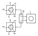
- FIG. 4 schematically illustrates two images I 1 and I 2 in which the region of interest 10 is shown with three markers 101 , 102 , 103 .
- the images I 1 and I 2 differ in that the markers 101 , 102 , 103 have a different appearance. They are contrasted to a greater or lesser extent. This difference in contrast is due to the absorption of the markers 101 , 102 , 103 which varies in relation to the energy used for acquisition E 2 .
- Obtaining radiological images E 3 consists either of acquiring the different radiological images, or retrieving radiological images that were stored after acquisition. These can be stored in the storage unit 7 of the medical imaging system.
- FIG. 4 illustrates the final image I in which the markers 101 , 102 , 103 have been deleted.
- the final image I is not deteriorated by this linear combination, only the markers are deleted.
- the method described in the foregoing can be implemented using a computer program comprising machine instructions for this purpose.
- the computer program can be stored on any ad hoe medium of known type, for example: hard disk, CD-ROM, DVD-ROM, diskette, USB flash drive, SD card. These storage means may also be kept on a local or remote server.
Abstract
Description
μ=αc·ƒc(E)+αp·ƒp(E).
Claims (15)
I=α log I 1+β log I 2,
I=α log I 1+β log I 2,
Applications Claiming Priority (2)
| Application Number | Priority Date | Filing Date | Title |
|---|---|---|---|
| FR1056780 | 2010-08-26 | ||
| FR1056780A FR2964228B1 (en) | 2010-08-26 | 2010-08-26 | PROCESSING OF RADIOLOGICAL IMAGES FOR DELETION OF MARKERS WITHOUT IMAGE DEGRADATION |
Publications (2)
| Publication Number | Publication Date |
|---|---|
| US20120051497A1 US20120051497A1 (en) | 2012-03-01 |
| US8942349B2 true US8942349B2 (en) | 2015-01-27 |
Family
ID=43797606
Family Applications (1)
| Application Number | Title | Priority Date | Filing Date |
|---|---|---|---|
| US13/218,514 Active 2032-12-28 US8942349B2 (en) | 2010-08-26 | 2011-08-26 | Processing of radiological images to delete markers without image deterioration |
Country Status (2)
| Country | Link |
|---|---|
| US (1) | US8942349B2 (en) |
| FR (1) | FR2964228B1 (en) |
Citations (3)
| Publication number | Priority date | Publication date | Assignee | Title |
|---|---|---|---|---|
| US4868857A (en) * | 1987-10-30 | 1989-09-19 | Duke University | Variable compensation method and apparatus for radiological images |
| US5359513A (en) | 1992-11-25 | 1994-10-25 | Arch Development Corporation | Method and system for detection of interval change in temporally sequential chest images |
| US5910972A (en) | 1996-09-25 | 1999-06-08 | Fuji Photo Film Co., Ltd. | Bone image processing method and apparatus |
-
2010
- 2010-08-26 FR FR1056780A patent/FR2964228B1/en not_active Expired - Fee Related
-
2011
- 2011-08-26 US US13/218,514 patent/US8942349B2/en active Active
Patent Citations (3)
| Publication number | Priority date | Publication date | Assignee | Title |
|---|---|---|---|---|
| US4868857A (en) * | 1987-10-30 | 1989-09-19 | Duke University | Variable compensation method and apparatus for radiological images |
| US5359513A (en) | 1992-11-25 | 1994-10-25 | Arch Development Corporation | Method and system for detection of interval change in temporally sequential chest images |
| US5910972A (en) | 1996-09-25 | 1999-06-08 | Fuji Photo Film Co., Ltd. | Bone image processing method and apparatus |
Non-Patent Citations (4)
| Title |
|---|
| Alvarez, Macovski, Lehmann et al: "Generalized image combinations in dual KVP digital radiography"; L.A. Lehmann, R.E. Alvarez, A. Macovski, W.R.Brody, N.J. Pelc, S.J. Riederer and A.L. Hall, Med. Phys. 8, 659 (1981), OI:10.1118/1.595025. |
| Bentum, M.J.; Arendsen, R.G.J.; Slump, C.H.; Mistretta, C.A.; Peppler, W.W.; Zink, F.E.; Lab. for Network Theory, Twente Univ. Design and realization of high speed single exposure dual energy image processing; Jun. 14-17, 1992; pp. 25-34. |
| Loeckx, D.; Maes, F.; Vandermeulen, D.; Suetens, P.; Medical Image Comput., University Hospital Gasthuisberg, Leuven, Belgium; "Temporal subtraction of thorax CR images using a statistical deformation model," Nov. 2003, vol. 22, issue 11, pp. 1490-1504. |
| Written Opinion and Search Report in connection with FR Patent Application No. 1056780 filed on Aug. 26, 2010, issued on Apr. 20, 2011. |
Also Published As
| Publication number | Publication date |
|---|---|
| US20120051497A1 (en) | 2012-03-01 |
| FR2964228A1 (en) | 2012-03-02 |
| FR2964228B1 (en) | 2012-09-28 |
Similar Documents
| Publication | Publication Date | Title |
|---|---|---|
| RU2634622C2 (en) | Protocol with dose optimisation for attenuation correction and location determination on hybrid scanners | |
| US5672877A (en) | Coregistration of multi-modality data in a medical imaging system | |
| US7539284B2 (en) | Method and system for dynamic low dose X-ray imaging | |
| US7592600B2 (en) | Diagnosis device for radiographic and nuclear medical examinations | |
| JP5676486B2 (en) | Model-based field expansion in nuclear imaging | |
| US10130320B2 (en) | X-ray CT apparatus and image diagnostic apparatus | |
| US9332955B2 (en) | Adaptive dual-pass targeted reconstruction and acquisition | |
| US8447009B2 (en) | Method and computed tomography scanner for carrying out an angiographic examination | |
| JP2012066075A (en) | System and method of notch filtration for dual energy ct | |
| DE102005048853A1 (en) | Medical imaging modality, e.g. for medical examination procedure of patient, has PET detector ring which records raw positron emission tomography image data of patient | |
| CN102727238A (en) | Ct system for use in multi-modality imaging system | |
| EP2723238B1 (en) | Interventional imaging | |
| JP2009236793A (en) | Method for creating image information, method for creating tomographic image information for tomographic photographing apparatus, and tomographic photographing apparatus | |
| Xu et al. | Technical assessment of a prototype cone‐beam CT system for imaging of acute intracranial hemorrhage | |
| US20120176412A1 (en) | Method and system for improved medical image analysis | |
| JP2009540935A (en) | System and method for determining the position of an object | |
| US20090016488A1 (en) | Medical diagnostic system and method for capturing medical image information | |
| US8942349B2 (en) | Processing of radiological images to delete markers without image deterioration | |
| US20180235573A1 (en) | Systems and methods for intervention guidance using a combination of ultrasound and x-ray imaging | |
| DE102005054226A1 (en) | Imaging medical modality for diagnosing e.g. tumor, has recording device arranged within magnetic resonance imaging test tube, and common display unit for displaying two images and attached to respective image processing units | |
| US11039803B1 (en) | System and method for cabinet radiography incorporating a gamma or other probe | |
| Majewski et al. | Compact and mobile high resolution PET brain imager | |
| KR20160026267A (en) | Medical image processing system and method | |
| JP5259213B2 (en) | Nuclear medicine diagnostic apparatus and medical image processing apparatus | |
| Buzug | Milestones of Computed Tomography |
Legal Events
| Date | Code | Title | Description |
|---|---|---|---|
| AS | Assignment |
Owner name: GENERAL ELECTRIC COMPANY, NEW YORK Free format text: ASSIGNMENT OF ASSIGNORS INTEREST;ASSIGNORS:BISMUTH, VINCENT;GORGES, SEBASTIEN;REEL/FRAME:026812/0973 Effective date: 20110825 |
|
| STCF | Information on status: patent grant |
Free format text: PATENTED CASE |
|
| MAFP | Maintenance fee payment |
Free format text: PAYMENT OF MAINTENANCE FEE, 4TH YEAR, LARGE ENTITY (ORIGINAL EVENT CODE: M1551) Year of fee payment: 4 |
|
| CC | Certificate of correction | ||
| MAFP | Maintenance fee payment |
Free format text: PAYMENT OF MAINTENANCE FEE, 8TH YEAR, LARGE ENTITY (ORIGINAL EVENT CODE: M1552); ENTITY STATUS OF PATENT OWNER: LARGE ENTITY Year of fee payment: 8 |