US8939342B2 - Cordless framing nailer - Google Patents
Cordless framing nailer Download PDFInfo
- Publication number
- US8939342B2 US8939342B2 US13/947,192 US201313947192A US8939342B2 US 8939342 B2 US8939342 B2 US 8939342B2 US 201313947192 A US201313947192 A US 201313947192A US 8939342 B2 US8939342 B2 US 8939342B2
- Authority
- US
- United States
- Prior art keywords
- driver
- driving tool
- nosepiece
- frame
- flywheel
- Prior art date
- Legal status (The legal status is an assumption and is not a legal conclusion. Google has not performed a legal analysis and makes no representation as to the accuracy of the status listed.)
- Active
Links
Images


Classifications
-
- B—PERFORMING OPERATIONS; TRANSPORTING
- B25—HAND TOOLS; PORTABLE POWER-DRIVEN TOOLS; MANIPULATORS
- B25C—HAND-HELD NAILING OR STAPLING TOOLS; MANUALLY OPERATED PORTABLE STAPLING TOOLS
- B25C1/00—Hand-held nailing tools; Nail feeding devices
- B25C1/06—Hand-held nailing tools; Nail feeding devices operated by electric power
-
- B—PERFORMING OPERATIONS; TRANSPORTING
- B25—HAND TOOLS; PORTABLE POWER-DRIVEN TOOLS; MANIPULATORS
- B25C—HAND-HELD NAILING OR STAPLING TOOLS; MANUALLY OPERATED PORTABLE STAPLING TOOLS
- B25C5/00—Manually operated portable stapling tools; Hand-held power-operated stapling tools; Staple feeding devices therefor
- B25C5/10—Driving means
- B25C5/15—Driving means operated by electric power
Definitions
- the present invention generally relates to driving tools and more particularly to a driving tool with a driver that can be selectively engaged to a rotating flywheel.
- Fastening tools such as power nailers and staplers
- the fastening tools that are available may not provide the user with a desired degree of flexibility and freedom due to the presence of hoses and such that couple the fastening tool to a source of pneumatic power.
- cordless nailers have been introduced to the market in an effort to satisfy the demands of modern consumers. Some of these nailers, however, are relatively large in size and/or weight, which render them relatively cumbersome to work with. Others require relatively expensive fuel cartridges that are not re-fillable by the user so that when the supply of fuel cartridges has been exhausted, the user must leave the work site to purchase additional fuel cartridges. Yet other cordless nailers are relatively complex in their design and operation so that they are relatively expensive to manufacture and do not operate in a robust manner that reliably sets fasteners into a workpiece in a consistent manner. Accordingly, there remains a need in the art for an improved fastening tool.
- the present teachings provide a driving tool having a frame, a motor coupled to the frame, a flywheel, a rail, a driver and a follower.
- the frame defines a rotational axis and a driver axis.
- the flywheel is rotatably driven by the motor about the rotational axis.
- the rail extends parallel to the driver axis.
- the driver is mounted on the rail and movable along the driver axis between a returned position and an extended position.
- the follower is coupled to the frame and is movable between a first position, in which the follower drives the driver into engagement with the flywheel to transfer energy from the flywheel to the driver to propel the driver along the driver axis, and a second position in which the follower, the driver and the flywheel are not engaged to one another.
- the present teachings provide a driving tool with a frame, a nosepiece, a motor, a flywheel, a pair of rails, a driver, a pair of springs and a follower.
- the frame defines a rotational axis and a driver axis.
- the nosepiece is coupled to the frame.
- the motor is coupled to the frame.
- the flywheel is rotatably driven by the motor about the rotational axis.
- the rails extend parallel to the driver axis and are disposed on opposite sides of the flywheel.
- the driver is mounted on the rails and is received into the nosepiece. The driver is movable along the driver axis between a returned position and an extended position.
- Each of the springs is received over a corresponding one of the rails and cooperates to bias the driver into the returned position.
- the follower is coupled to the frame and is movable between a first position, in which the follower drives the driver into engagement with the flywheel to transfer energy from the flywheel to the driver to propel the driver along the driver axis, and a second position in which the follower, the driver and the flywheel are not engaged to one another.
- the rails are movable relative to the frame in a direction toward the rotational axis when the driver is driven by the follower into engagement with the flywheel.
- the present teachings provide a driving tool having a motor assembly with an electric motor-driven flywheel, a driver and a follower that is selectively movable to drive the driver into engagement with a rotating perimeter of the flywheel.
- the driver is unitarily formed and includes driver body and a driver blade.
- the driver body includes a driver profile on one side, which is configured to engage the perimeter of the flywheel, and a cam on an opposite side that is configured to aid in the loading and unloading of the follower with movement of the driver.
- FIG. 1A is a side elevation view of an exemplary driving tool constructed in accordance with the teachings of the present disclosure
- FIG. 1B is a bottom plan view of a portion of the driving tool of FIG. 1 illustrating the backbone and drive motor assembly in more detail;
- FIG. 1C is a rear view of a portion of the driving tool of FIG. 1 illustrating the backbone and drive motor assembly in more detail;
- FIG. 1D is a perspective view of a portion of the driving tool of FIG. 1 ;
- FIG. 2 is an exploded perspective view of a portion of the driving tool of FIG. 1 , illustrating the backbone and the power source in more detail;
- FIG. 3 is an exploded perspective view of a portion of the driving tool of FIG. 1 illustrating the backbone, transmission and motor in more detail;
- FIG. 4 is a perspective view of a portion of the driving tool of FIG. 1 illustrating the driver and the power source in more detail;
- FIG. 5 is an exploded perspective view of a portion of the driving tool of FIG. 1 illustrating the transmission and a second gearcase member in more detail;
- FIGS. 5A and 5B are exploded perspective views similar to that of FIG. 5 but illustrating alternatively configured transmissions that utilize pulleys and a power transmitting belt;
- FIG. 6 is an end view of a portion of the driving tool of FIG. 1 illustrating the construction of the lug members on the isolation plate of the transmission;
- FIG. 7 is a perspective view of a portion of the power source illustrating the driver in more detail
- FIG. 8 is a section view of a portion of the driving tool of FIG. 1 illustrating the driver as received into the nosepiece assembly;
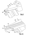
- FIG. 9 is a perspective view of a portion of the driving tool of FIG. 1 illustrating the nosepiece in more detail;
- FIG. 10 is a longitudinal section view taken through a portion of the nosepiece
- FIG. 11 is a perspective view of a portion of another driving tool constructed in accordance with the teachings of the present disclosure illustrating the return mechanism and driver;
- FIG. 12 is a schematic illustration of the driving tool of FIG. 11 , illustrating the return mechanism and driver positioned in relation to a nosepiece, a flywheel and a follower;
- FIG. 13 is an enlarged view of a portion of the return mechanism and driver that are illustrated in FIG. 12 ;
- FIG. 14 is a schematic illustration of the driving tool of FIG. 1 , illustrating the controller
- FIG. 15 is a plot illustrating the supply of electrical power to the motor using a pulse-width modulation technique for operation of the driving tool of FIG. 1 ;
- FIG. 16 is a perspective view of a portion of another driving tool constructed in accordance with the teachings of the present disclosure.
- FIG. 17 is a perspective view of a portion of the driving tool of FIG. 16 illustrating the driver and the return mechanism in greater detail;
- FIG. 18 is an enlarged portion of FIG. 17 .
- a driving tool constructed in accordance with the teachings of the present invention is generally indicated by reference numeral 10 .
- the driving tool 10 may include a housing and magazine assembly 12 , a backbone 14 , a backbone cover 16 , a drive motor assembly 18 , a control unit 20 , a nosepiece assembly 22 and a battery pack 26 . While the driving tool 10 is illustrated as being electrically powered by a suitable power source, such as the battery pack 26 , those skilled in the art will appreciate that the invention, in its broader aspects, may be constructed somewhat differently and that aspects of the present invention may have applicability to pneumatically powered driving tools.
- the drive motor assembly 18 may also be employed in various other mechanisms that utilize reciprocating motion, including rotary hammers, hole forming tools, such as punches, and riveting tools, such as those that install deformation rivets.
- the battery pack 26 may be of any desired type and may be rechargeable, removable and/or disposable. In the particular example provided, the battery pack 26 is rechargeable and removable and may be a battery pack that is commercially available and marketed by the DeWalt Industrial Tool Company of Baltimore, Md.
- the backbone 14 may be a structural element upon which the drive motor assembly 18 , the control unit 20 , the nosepiece assembly 22 , and/or the housing and magazine assembly 12 may be fully or partially mounted.
- the drive motor assembly 18 may be of any desired configuration, but in the example provided, includes a power source 30 , a driver 32 , a follower assembly 34 , and a return mechanism 36 .
- the power source 30 includes a motor 40 , a transmission 5000 , a flywheel 42 , and an actuator 44 .
- fasteners F which are stored in the housing and magazine assembly 12 , are sequentially fed into the nosepiece assembly 22 .
- the drive motor assembly 18 may be actuated by the control unit 20 to cause the driver 32 to translate and impact a fastener F that resides in the nosepiece assembly 22 so that the fastener F may be driven into a workpiece (not shown).
- Actuation of the power source may utilize electrical energy from the battery pack 26 to operate the motor 40 and the actuator 44 .
- the motor 40 is employed to drive the flywheel 42
- the actuator 44 is employed to move a follower 50 that is associated with the follower assembly 34 , which squeezes the driver 32 into engagement with the flywheel 42 so that energy may be transferred from the flywheel 42 to the driver 32 to cause the driver 32 to translate.
- the follower 50 which can be a roller, can be coupled to the backbone 14 and can be moved via the actuator 44 between a first position, in which the follower 50 drives the driver 32 into the rotating perimeter of the flywheel 42 to transfer energy from the flywheel 42 to the driver 32 to propel the driver 32 along the driver axis 118 , and a second position in which the follower 50 , the driver 50 and the flywheel 42 are not engaged to one another.
- the nosepiece assembly 22 guides the fastener F as it is being driven into the workpiece.
- the return mechanism 36 biases the driver 32 into a returned position.
- the housing and magazine assembly 12 can include a pair of discrete housing shells 2400 and a pusher assembly 5002 .
- the housing shells 2400 can be formed from a thermoplastic material and can cooperate to define a tool body portion 2402 , a handle portion 2404 , and a magazine portion 2406 .
- the body portion 2402 may define a housing cavity 2410 that is sized to receive the backbone 14 , the drive motor assembly 18 and the control unit 20 therein.
- the handle portion 2404 may extend from the body portion 2402 and may be configured in a manner that permits an operator to manipulate the driving tool 10 in a convenient manner.
- the handle portion 2404 may include a mount 2418 to which the battery pack 26 may be releasably coupled.
- the pusher assembly 5002 can include a spring-biased pusher 5006 that can be housed in the magazine portion 2406 .
- the magazine portion 2406 can cooperate with the pusher assembly 5002 to hold a plurality of fasteners F and sequentially dispense the fasteners F into the nosepiece assembly 22 .
- one or more guide rails (not specifically shown), which can be formed of a suitably wear-resistant material, can be coupled to the housing shells 2400 to cover portions of the housing shells 2400 that would otherwise directly contact the fasteners F and/or portions of the pusher assembly 5002 in the magazine portion 2406 .
- portions of the housing shells 2400 can be overmolded to create areas on the exterior of and/or within the housing and magazine assembly 12 that enhance the capability of the housing and magazine assembly 12 to be gripped by an operator, provide vibration damping, and/or form one or more seals.
- Such techniques are described in more detail in commonly assigned U.S. Pat. No. 6,431,289 entitled “Multispeed Power Tool Transmission”, which is hereby incorporated by reference as if fully set forth in detail herein.
- the backbone 14 can define a motor mount 60 , a flywheel mount 66 , first and second activation arm mounts 68 a and 68 b and a nosepiece mount 70 .
- the backbone 14 includes a first backbone member 5010 , a second backbone member 5012 , a first gearcase member 5014 and a second gearcase member 5016 .
- first gearcase member 5014 is illustrated and described below as being a discrete component that is coupled to the first and second backbone members 5010 and 5012 , the first gearcase member 5014 could be integrally formed with the second backbone member 5012 .
- Each of the first and second backbone members 5010 and 5012 and the first and second gearcase members 5014 and 5016 can be die cast from a suitable structural material, such as magnesium or aluminum.
- the first gearcase member 5014 can define a first case portion 5020 and a second case portion 5022 (i.e., the motor mount 60 ).
- the first case portion 5020 can include a rear wall 5028 and an annular sidewall 5030 that can be disposed about the outer perimeter of the rear wall 5028 .
- the rear wall 5028 and the annular sidewall 5030 can cooperate to define a gear cavity 5032 .
- the second case portion 5022 can have a hollow semi-spherical shape that can define a mounting aperture 5034 , an annular surface 5036 that can be disposed about the mounting aperture 5034 , and a first bearing mount 5038 .
- the mounting aperture 5034 can receive at least the output shaft 40 a of the motor 40 .
- the motor 40 is abutted against the annular surface 5036 and threaded fasteners 5040 are received through fastener apertures 5042 in the annular surface 5036 and threadably engaged to corresponding threaded holes (not shown) in the motor 40 to thereby fixedly but removably couple the motor 40 to the motor mount 60 .
- one or more spacers can be disposed between the annular surface 5036 and the motor 40 to control the position of the motor 40 relative to a datum of the motor mount 60 . It will be appreciated that other mounting/alignment techniques may be employed to mount the motor 40 in the motor mount 60 in a desired orientation.
- the body 40 b of the motor 40 can be press-fit into the mounting aperture 5034 or threaded into the mounting aperture 5034 .
- Mounting of the motor 40 in the manner illustrated permits the rotational axis 40 c of the motor 40 to be oriented generally parallel and in a common plane with the axis 118 along which the driver 32 translates to thereby reduce the overall width of the driving tool 10 relative to the width of the driving tool that is illustrated and described in U.S. Pat. No. 7,204,403.
- the second gearcase member 5016 can be removably coupled to the first gearcase member 5014 via a plurality of fasteners 5044 to close a side of the gear cavity 5032 opposite the rear wall 5028 .
- the second gearcase member 5016 can define a second bearing mount 5050 .
- the flywheel mount 66 can include a third bearing mount 5100 in the second gearcase member 5016 and a fourth bearing mount 5102 that can be formed in the first backbone member 5010 .
- a transmission output shaft 5110 can be received through a hole 5112 in the first gearcase member 5014 and supported on bearings 5114 and 5116 that can be received into the third and fourth bearing mounts 5100 and 5102 , respectively.
- the flywheel 42 can be coupled for rotation with the transmission output shaft 5110 .
- a pin 3040 can be received through the opposite arms 3000 of the follower assembly 34 and into corresponding apertures in the first activation arm mount 64 a to thereby fixedly couple a first end of the follower assembly 34 to the backbone 14 .
- a pair of threaded fasteners 3041 can be received through the opposite arms 3000 of the follower assembly 34 and into corresponding apertures in the second activation arm mount 64 b to thereby fixedly couple a second end of the follower assembly 34 to the backbone 14 .
- the nosepiece mount 70 may include a pair of flanges 220 that can extend outwardly in the direction in which the driver 32 is advanced (or extended).
- the nosepiece assembly 22 can be coupled to the nosepiece mount 70 in any desired manner. For example, threaded fasteners (not shown) can be received through holes H (only one shown) in the flanges 220 and threadably coupled to the nosepiece assembly 22 .
- the transmission 5000 can be mounted to the backbone 14 and can include a plurality of gears 5200 that transmit rotary power between the output shaft 40 a of the motor 40 and the output shaft 5110 of the transmission 5000 .
- the plurality of gears 5200 can be of any desired configuration and can include for example spur and/or bevel gears having straight and/or helical teeth.
- a bevel pinion 5204 is non-rotatably coupled to the output shaft 40 a of the motor 40 and received through the mounting aperture 5034 into the hollow interior of the second case portion 5022 .
- An intermediate shaft 5206 can be supported on a pair of bearings 5208 and 5210 ; each of the bearings 5208 and 5210 is received in an associated one of the first and second bearing mounts 5038 and 5050 .
- a bevel idler gear 5212 can be received on the intermediate shaft 5206 and meshingly engaged with the bevel pinion 5204 .
- a spur idler gear 5214 can be coupled for rotation with the bevel idler gear 5212 .
- the transmission output shaft 5110 can be supported on the bearings 5114 and 5116 in the third and fourth bearing mounts 5100 and 5102 , respectively.
- An output gear assembly 5220 can be mounted on the transmission output shaft 5110 and can be meshingly engaged with the spur idler gear 5214 .
- the output gear assembly 5220 can include an isolation plate 5222 , an output spur gear 5224 , a bearing 5226 , a plate member 5228 and a plurality of isolation plugs 5230 .
- the isolation plate 5222 can include a hub 5240 , an annular plate member 5241 that can be coupled to and extend outwardly from the hub 5240 , and a plurality of arcuate lugs 5242 .
- the hub 5240 can be configured to mount the isolation plate 5222 to the transmission output shaft 5110 in any desired manner, such as via an interference fit (e.g., press fit) that involves an aperture 5244 in the hub 5240 and the outer diameter of the portion of the transmission output shaft 5110 to which the hub 5240 is coupled.
- an interference fit e.g., press fit
- various features such as a shoulder 5246 , can be incorporated into the transmission output shaft 5110 and/or the isolation plate 5222 so that these components can be joined to one another in a desired manner.
- the isolation plate 5222 may be pressed onto the transmission output shaft 5110 such that the hub 5240 is abutted against the shoulder 5246 .
- the arcuate lugs 5242 can extend from a side of the annular plate member 5241 and can be disposed about a common (circular) axis 5242 a about a rotational axis 5110 a of the transmission output shaft 5110 .
- Each of the arcuate lugs 5242 can include a first end 5250 , which can be defined by a radius (whose center point can lie on the common circular axis 5242 a ) and can have a convex cylindrical shape, and a second end 5252 opposite the first end 5250 , which can be defined by a radius (whose center point can lie on the common circular axis 5242 a ) and can have a concave cylindrical shape.
- the output spur gear 5224 can include a through-hole 5260 , a plurality of teeth 5262 that can be meshingly engaged to the teeth 5264 of the spur idler gear 5214 , and a plurality of arcuate slots 5270 that can be configured to receive the arcuate lugs 5242 of the isolation plate 5222 .
- Each of the arcuate slots 5270 can have a first end 5272 , which can be complementary in shape to the first end 5250 of the arcuate lugs 5242 , and a second end 5274 opposite the first end 5272 .
- the bearing 5226 can be received between the transmission output shaft 5110 and the output spur gear 5224 so as to support the output spur gear 5224 for rotation on the transmission output shaft 5110 .
- the plate member 5228 can be received on the transmission output shaft 5110 on a side of the output spur gear 5224 opposite the annular plate member 5228 of the isolation plate 5222 .
- Each of the isolation plugs 5230 can be formed of a resilient material.
- Each isolation plug 5230 can be generally cylindrical in shape and can be received between the concave second end 5252 of an associated one of the arcuate lugs 5242 and a second end 5274 of an associated one of the arcuate slots 5270 .
- the shape of the second end 5274 of the arcuate slots 5270 and the portion of the isolation plugs 5230 that contact the second end 5274 of the arcuate slots 5270 can be configured in any desired manner and can be sized and shaped to inhibit rotational movement of one or more of the isolation plugs 5230 relative to the output spur gear 5224 (e.g., the second end 5274 of the arcuate slot 5270 could include a “bow-tie” or “dog bone” shape and the isolation plugs 5230 could be shaped to resiliently engage such “bow-tie” or “dog bone” shape).
- Power can be transmitted through the transmission 5000 such that the output spur gear 5224 is rotated in a direction that tends to compress the isolation plugs 5230 against the second ends 5252 of the arcuate lugs 5242 (i.e., in the direction of arrow A in FIG. 6 ).
- the isolation plugs 5230 can be configured to further compress when the rotational inertia of the transmission 5000 is greater than the rotational inertia of the flywheel 42 (e.g., upon start-up of the motor 40 or after the flywheel 42 has decelerated due to transmission of energy to the driver 32 ). In such situations, the compliant nature of the isolation plugs 5230 serves to relieve some of the stress on the teeth 5262 of the output spur gear 5224 .
- the transmission 5000 has been illustrated and described as including a spur idler gear 5214 and an output gear assembly 5220 , those of skill in the art will appreciate that the transmission could be configured somewhat differently.
- the transmission 5000 ′ of FIG. 5A substitutes a pair of pulleys 5214 ′ and 5220 ′ and a belt B for the spur idler gear 5214 and the output gear assembly 5220 of FIG. 5
- the transmission 5000 ′′ of FIG. 5B substitutes a pair of pulleys 5214 ′ and 5224 ′ and a belt B for the spur idler gear 5214 and the output spur gear 5224 of FIG. 5 .
- the driver 32 can be unitarily formed in a suitable casting process (e.g., investment casting) from a suitable material, such as steel.
- the driver 32 can include an upper driver member 500 and a driver blade 502 .
- the upper driver member 500 can include a body 510 and a pair of projections 512 .
- the projections 515 can extend from the opposite lateral sides of the body 510 and can include return anchors 630 (i.e., points at which the driver 32 is coupled to the return mechanism 36 ) and bumper tabs 632 which include contact surfaces 670 that are configured to contact a lower bumper (not shown).
- the body 510 can include a driver profile 520 (e.g., a surface, such as one with a plurality of V-shaped teeth, that is configured to engage the perimeter of a rotating flywheel as illustrated and described in U.S. patent application Ser. No. 11/586,104) and a cam profile 522 (e.g., a profile with a loading cam and an unloading cam as illustrated and described in U.S. patent application Ser. No. 11/586,104 that is configured to aid in the loading and unloading of the follower with movement of the driver along a driver axis).
- a driver profile 520 e.g., a surface, such as one with a plurality of V-shaped teeth, that is configured to engage the perimeter of a rotating flywheel as illustrated and described in U.S. patent application Ser. No. 11/586,104
- a cam profile 522 e.g., a profile with a loading cam and an unloading cam as illustrated and described in U.S. patent application Ser. No.
- the driver blade 502 can be configured in any desired manner, such as with a generally rectangular cross-section (taken latterly in a direction perpendicular to the longitudinal axis of the driver blade 502 ).
- the driver blade 502 has a generally half-moon cross-section having a longitudinally extending key-slot 5300 formed on a top surface of the driver blade 502 .
- the key-slot 5300 can be configured to receive a correspondingly shaped key member 5302 formed on or coupled to the nosepiece assembly 22 .
- the key-slot 5300 and the key member 5302 can cooperate to inhibit rotation of the driver 32 relative to the flywheel 42 .
- the nosepiece assembly 22 can be configured to receive a portion of the upper driver member 500 when the driver 32 is driven forwardly to drive a fastener F ( FIG. 1A ).
- the nosepiece assembly 22 can include an upper nosepiece member 5350 , a lower nosepiece member 5352 , and a pair of sidewalls 5354 that can couple the upper nosepiece member 5350 to the lower nosepiece member 5352 .
- the upper and lower nosepiece members 5350 and 5352 and the sidewalls 5354 can cooperate to define a nosepiece cavity 5356 into which a portion of the body 510 of the upper driver member 500 can be received.
- the key member 5302 can be coupled to the upper nosepiece member 5350 and can extend into the nosepiece cavity 5356 .
- the nosepiece assembly 22 can be unitarily formed in a suitable process, such as investment casting, or can be formed as one or more components.
- the nosepiece assembly 22 includes a lower nosepiece structure 5400 and an upper nosepiece structure 5402 .
- the lower nosepiece structure 5400 can be formed of a suitable material, such as steel, in a suitable process, such as investment casting, and can be removably coupled to the backbone 14 ( FIG. 2 ) and the housing and magazine assembly 12 ( FIG. 1A ) to receive fasteners F ( FIG. 1A ) from the magazine portion 2406 ( FIG. 1A ).
- the upper nosepiece structure 5402 can include a wear plate 5410 and an outer member 5412 .
- the outer member 5412 can be formed of a suitable material, such as die-cast aluminum, and can be coupled to the wear plate 5410 in a suitable manner.
- the wear plate 5410 is formed of steel and is molded into the outer member 5412 (i.e., the outer member 5412 is molded onto the wear plate 5410 ).
- the outer member 5412 can be integrally formed with the backbone 14 ( FIG. 1D ) and the wear plate 5410 can be formed of steel and fixedly coupled to the outer member 5412 in any desired manner.
- driver 32 has been illustrated and described as employing the projections 515 that are described in U.S. Patent No. 7 , 204 , 403 , those of skill in the art will appreciate that the driver 32 could be constructed somewhat differently.
- the driver 32 a can be configured to include a pair of projections 512 a as illustrated in FIGS. 11 through 13 .
- the projections 512 a can extend from the opposite lateral sides of the body 510 a and can include return anchors 630 a (i.e., points at which the driver 32 is coupled to the return mechanism 36 a ) and bumper tabs 632 a which include contact surfaces 670 a that are configured to contact a lower bumper 2102 a that can be received into a pocket P formed into the nosepiece assembly 22 .
- Each of the return anchors 630 a can define an anchor hole 5450 , which can extend through an associated one of the projections 512 a generally parallel to the driver blade 502 .
- the return mechanism 36 a can include a rail assembly 5460 , a pair of compression springs 5462 and a rail pivot 5464 .
- the rail assembly 5460 can include a pair of rails 5470 an end cap 5472 that can be coupled to an upper end 5474 of the rails 5470 .
- the rails 5470 can be formed of a low friction material, such as hardened steel, and can be employed to guide the driver 32 a when the driver 32 a is moved to the returned position.
- a pair of hollow guide members 5476 can be formed of a lubricious material, such as acetyl, and can be fitted over the rails 5470 and into the anchor holes 5450 to guide the driver 32 a as the driver 32 a is moved on the rails 5470 .
- the compression springs 5462 can be received over the rails 5470 on an end opposite the end cap 5472 and can be abutted against the contact surfaces 670 a.
- the hollow guide members 5476 can be received into and engage the inner diametrical surface of the compression springs 5462 .
- the compression springs 5462 can be relatively long so as to have a relatively high return force, which can be desirable where the full travel of the driver 32 a is relatively short and/or where the pusher 5006 ( FIG. 1A ) applies a relatively high force to the fasteners F ( FIG. 1A ) in the housing and magazine assembly 12 ( FIG. 1A ).
- the compression springs 5462 are relatively long, the stress generated in the compression springs 5462 when the driving tool 10 ( FIG.
- the compression springs 5462 are anticipated to have a relatively long fatigue life in spite of the dynamic loading that they will experience.
- the pockets P in the nosepiece assembly 22 permit the relatively long rails 5470 and compression springs 5462 to be packaged into the tool without enlarging the size of the tool.
- the lower bumpers 2102 a can be generally hollow and cylindrical in shape with an upper contact surface 670 b that is defined by a spherical radius. Each of the lower bumpers 2102 a can be received over an associated one of the compression springs 5462 and can be received in a lower bumper pocket 5480 ( FIG. 2 ) that is formed in the backbone 14 ( FIG. 2 ).
- the rail pivot 5464 can resiliently support a lower end 5482 of the rails 5470 so as to urge the rails 5470 away from the flywheel 42 .
- a compression spring 5484 can be employed to urge the end cap 5472 away from the flywheel 42 .
- the rail pivot 5464 and the compression spring 5484 can cooperate to maintain the rails 5470 in a position that spaces the driver 32 a apart from the flywheel 42 .
- the follower 50 is driven into contact with the cam profile 522 of the driver 32 a and urges the driver 32 a downwardly toward the flywheel 42 .
- the rail pivot 5464 and the compression spring 5484 that support the lower and upper ends 5482 and 5474 of the rails 5470 can move toward the flywheel 42 in response to the force applied by the follower 50 to permit the driver profile 520 of the driver 32 a to engage the flywheel 42 .
- FIG. 16 Another driver constructed in accordance with the teachings of the present disclosure is illustrated in FIG. 16 and identified by reference numeral 10 b. Except as described herein, the driver 32 b can be generally similar to the driver 32 a illustrated in FIGS. 11 through 13 and discussed in detail above. With additional reference to FIGS. 17 and 18 , the projections 512 b of the driver 32 b can extend from the opposite lateral sides of the body 510 b and can include integrally-formed return anchors 630 b and bumper tabs 632 b that include contact surfaces 670 b that are configured to contact a lower bumper 2102 b.
- Each of the return anchors 630 b can define an anchor hole 5450 b, which can extend through an associated one of the projections 512 b generally parallel to the driver blade 502 b.
- the contact surfaces 670 b can be shaped in a desired manner, but are flat in the particular example provided.
- the return mechanism 36 b can include a rail assembly 5460 b and a pair of compression springs 5462 b.
- the rail assembly 5460 b can include a pair of rails 5470 b and an end cap 5472 b that can be coupled to an upper end 5474 b of the rails 5470 b.
- the rails 5470 b can be formed of a low friction material, such as hardened steel, and can be received through the anchor holes 5450 b and employed to guide the driver 32 b when the driver 32 b is moved to the returned position.
- the end cap 5472 b can include an aperture 6000 through which the driver 32 b can either extend or be accessed by an upper bumper (not shown), which is coupled to the backbone or frame 14 b (schematically illustrated in FIG.
- the upper bumper can include an energy absorbing member so as to dampen the impact forces transmitted to the backbone 14 b when the driver 32 b is moved to the returned position.
- the compression springs 5462 b can be received coaxially over the rails 5470 b on an end opposite the end cap 5472 b and can be abutted against the return anchors 630 b.
- the compression springs 5462 b have ground ends and as such, the return anchors 630 b have a flat surface against which the compression springs 5462 b are abutted.
- the compression springs 5462 b could have open or closed ends that are not ground and the surface of the return anchors 630 b can be at least partly contoured in a helical manner to matingly engage the unground ends of the compression springs 5462 b ).
- the compression springs 5462 b can be configured to provide a relatively long fatigue life in spite of the dynamic loading that they will experience.
- the compression springs 5462 b can be formed of several wires 6010 that can be twisted about one another and collectively coiled in a helical manner.
- each compression spring 5462 b can be formed of three wires formed of 0.018 inch diameter M4 music wire that can be twisted at a rate of nine (9) turns per inch.
- the compression springs 5462 b can be configured with a coil pitch (i.e., the distance between adjacent coils 6012 of the compression spring 5462 b ) and at least two different coil pitches can be employed to define each of the compression springs 5462 b.
- Each compression spring 5462 b can employ a first coil pitch at a first end 6016 that is abutted against the return anchor 630 b, and a second coil pitch at a second end 6018 opposite the first end 6016 .
- the coil pitch can vary between the first and second ends and for example, can become progressively smaller with decreasing distance to the second end.
- the compression springs 5462 b can be formed of 0.028 inch M4 music wire, the first coil pitch can be 3.00 mm and the second coil pitch can be 1.20 mm.
- Impact absorbers 6020 can be employed in conjunction with the compression springs 5462 b to further protect the compression springs 5462 from fatigue.
- the impact absorbers 6020 include first and second impact structures 6022 and 6024 , respectively and a damper 6026 that can be disposed between the first and second impact structures 6022 and 6024 .
- Each of the first and second impact structures 6022 and 6024 can be formed of a suitable impact-resistant material, such as glass-filled nylon or hardened steel, which can be directly contacted by the compression springs 5462 b, while the damper 6026 can be formed of a suitable impact absorbing material, such as chlorobutyl rubber.
- the impact absorbers 6020 can be sleeve-like structures that can be fitted coaxially over an associated one of the rails 5470 b between the second end 6018 of the compression springs 5462 b and the backbone or frame 14 b.
- the backbone 14 b can be configured with pockets 6030 to at least partly receive the impact absorbers 6020 but it will be appreciated that the backbone 14 b and impact absorbers 6020 are not configured to cooperate to maintain the rails 5470 b in a fixed, non-movable orientation relative to the backbone 14 b. Rather, the rails 5470 b are provided with a degree of movement (toward and away from the rotational axis 6036 of the flywheel 42 b ).
- the nosepiece 22 b includes an aperture (not shown) that is shaped and sized to correspond to a cross-sectional shape and size of the driver blade 502 .
- the driving tool 10 can include a mode selector switch 60 - 1 .
- the mode selector switch 60 - 1 can be employed by the user of the driving tool 10 to set the driving tool 10 into a (first) sequential mode, a bump mode or a second sequential mode.
- the mode selector switch 60 - 1 , the (first) sequential mode and the bump mode are described in more detail in U.S. patent application Ser. No. 11/095,721 entitled “Fastening Tool With Mode Selector Switch”, the disclosure of which is hereby incorporated by reference as if fully set forth in detail herein.
- the mode selector switch 60 - 1 can be a switch that produces a mode selector switch signal that is indicative of a desired mode of operation of the driving tool 10 .
- One mode of operation may be, for example, a sequential fire mode wherein a contact trip 20 - 1 must first be abutted against a workpiece (so that a contact trip sensor 50 - 1 generates a contact trip sensor signal) and thereafter a trigger switch 18 a - 1 is actuated to generate a trigger signal.
- Another mode of operation may be a mandatory bump feed mode wherein the trigger switch 18 a - 1 is first actuated to generate the trigger signal and thereafter the contact trip 20 - 1 abutted against a workpiece so that the contact trip sensor 50 - 1 generates the contact trip sensor signal.
- Yet another mode of operation may be a combination mode that permits either sequential fire or bump feed wherein no particular sequence is required (i.e., the trigger sensor signal and the contact trip sensor signal may be made in either order or simultaneously).
- the mode selector switch 60 - 1 is a three-position switch that permits the user to select either a first sequential fire mode, the combination mode or a second sequential mode.
- the second sequential mode can be generally similar to the first sequential mode, except that the target or desired rotational speed of the flywheel 42 is changed in a desired manner that may be pre-programmed by the manufacturer of the driving tool 10 or selectively pre-programmed by the user of the driving tool 10 .
- the first sequential mode and the combination mode are configured such that the control unit 20 controls the power that is provided to the motor 40 to cause the flywheel 42 to rotate at or about a first target speed
- the second sequential mode is configured such that the control unit 20 controls the power that is provided to the motor 40 to cause the flywheel 42 to rotate at or about a second target speed that is greater than the first target speed.
- Configuration in this manner permits standard-duty operations, such as sheathing and framing, to be performed in the first sequential mode and the combination mode, and heavy-duty operations, such as fastening laminated veneer lumber (LVL) or hard woods, to be performed in the second sequential mode.
- standard-duty operations such as sheathing and framing
- heavy-duty operations such as fastening laminated veneer lumber (LVL) or hard woods
- control unit 20 can employ pulse width modulation (PWM), DC/DC converters, and precise on-time control to control the operation of the motor 40 and the actuator 44 , for example to ensure consistent speed of the flywheel 42 regardless of the voltage of the battery.
- PWM pulse width modulation
- the control unit 20 can be configured to sense or otherwise determine the actual or nominal voltage of the battery pack 26 at start-up (e.g., when the battery pack 26 is initially installed or electrically coupled to the controller 54 ). Power can be supplied to the motor 40 over all or a portion of a cycle using a pulse-width modulation technique, an example of which is illustrated in FIG. 15 .
- the cycle which may be initiated by a predetermined event, such as the actuation of the trigger 18 - 1 , may include an initial power interval 120 - 1 and one or more supplemental power intervals (e.g., 126 a - 1 , 126 b - 1 , 126 c - 1 ).
- the initial power interval 120 - 1 may be an interval over which the full voltage of the battery pack 26 may be employed to power the motor 40 .
- the length or duration (ti) of the initial power interval 120 - 1 may be determined through an algorithm or a look-up table in the memory of the control unit 20 for example, based on the output of the battery pack 26 or on an operating characteristic, such as rotational speed, of a component in the motor assembly 14 and the position of the mode selector switch 60 - 1 .
- the length or duration (ts) of each supplemental power interval may equal that of the initial power interval 120 - 1 , or may be a predetermined constant, or may be varied based on the output of the battery pack 26 or on an operating characteristic of the drive motor assembly 18 .
- a dwell interval 122 - 1 may be employed between the initial power interval 120 - 1 and a first supplemental power interval 126 a - 1 and/or between successive supplemental power intervals.
- the dwell intervals 122 - 1 may be of a varying length or duration (td), but in the particular example provided, the dwell intervals 122 - 1 are of a constant duration (td).
- power to the motor 40 may be interrupted so as to permit the motor 40 to “coast”.
- the output of a power source sensor 52 - 1 may be employed during this time to evaluate the level of kinetic energy in the drive motor assembly 18 (e.g., to permit the control unit 20 to determine whether the drive motor assembly 18 has sufficient energy to drive a fastener) and/or to determine one or more parameters by which the motor 40 may be powered or operated in a subsequent power interval.
- the control unit 20 evaluates the back emf of the motor 40 to approximate the speed of the flywheel 42 .
- the approximate speed of the flywheel 42 (or an equivalent thereof, such as the value of the back emf of the motor 40 ) may be employed in an algorithm or look-up table to determine the duty cycle (e.g., apparent voltage) of the next supplemental power interval.
- an algorithm or look-up table may be employed to calculate changes to the duration (ti) of the initial power interval 120 - 1 . In this way, the value (ti) may be constantly updated as the battery pack 26 is discharged.
- the value (ti) may be reset (e.g., to a value that may be stored in a look-up table) when a battery pack 26 is initially coupled to the control unit 20 .
- the control unit 20 may set (ti) equal to 180 ms if the battery pack 26 has a nominal voltage of about 18 volts, or to 200 ms if the battery pack 26 has a nominal voltage of about 14.4 volts, or to 240 ms if the battery pack 26 has a nominal voltage of about 12 volts.
Abstract
A driving tool with a driver and a motor-driven flywheel that can be engaged by the driver to propel the driver along a driver axis. The driving tool includes a return mechanism with a rail onto which the driver is received. The rail extends parallel to the driver axis.
Description
This application is a continuation of U.S. patent application Ser. No. 12/417,242 filed Apr. 2, 2009, which claims the benefit of U.S. Provisional Patent Application No. 61/041,946 filed Apr. 3, 2008. The disclosure of each of the above-mentioned applications is incorporated by reference as if fully set forth in detail herein.
The present invention generally relates to driving tools and more particularly to a driving tool with a driver that can be selectively engaged to a rotating flywheel.
Fastening tools, such as power nailers and staplers, are relatively common place in the construction trades. Often times, however, the fastening tools that are available may not provide the user with a desired degree of flexibility and freedom due to the presence of hoses and such that couple the fastening tool to a source of pneumatic power.
Recently, several types of cordless nailers have been introduced to the market in an effort to satisfy the demands of modern consumers. Some of these nailers, however, are relatively large in size and/or weight, which render them relatively cumbersome to work with. Others require relatively expensive fuel cartridges that are not re-fillable by the user so that when the supply of fuel cartridges has been exhausted, the user must leave the work site to purchase additional fuel cartridges. Yet other cordless nailers are relatively complex in their design and operation so that they are relatively expensive to manufacture and do not operate in a robust manner that reliably sets fasteners into a workpiece in a consistent manner. Accordingly, there remains a need in the art for an improved fastening tool.
This section provides a general summary of some aspects of the present disclosure and is not a comprehensive listing or detailing of either the full scope of the disclosure or all of the features described therein.
In one form, the present teachings provide a driving tool having a frame, a motor coupled to the frame, a flywheel, a rail, a driver and a follower. The frame defines a rotational axis and a driver axis. The flywheel is rotatably driven by the motor about the rotational axis. The rail extends parallel to the driver axis. The driver is mounted on the rail and movable along the driver axis between a returned position and an extended position. The follower is coupled to the frame and is movable between a first position, in which the follower drives the driver into engagement with the flywheel to transfer energy from the flywheel to the driver to propel the driver along the driver axis, and a second position in which the follower, the driver and the flywheel are not engaged to one another.
In another form, the present teachings provide a driving tool with a frame, a nosepiece, a motor, a flywheel, a pair of rails, a driver, a pair of springs and a follower. The frame defines a rotational axis and a driver axis. The nosepiece is coupled to the frame. The motor is coupled to the frame. The flywheel is rotatably driven by the motor about the rotational axis. The rails extend parallel to the driver axis and are disposed on opposite sides of the flywheel. The driver is mounted on the rails and is received into the nosepiece. The driver is movable along the driver axis between a returned position and an extended position. Each of the springs is received over a corresponding one of the rails and cooperates to bias the driver into the returned position. The follower is coupled to the frame and is movable between a first position, in which the follower drives the driver into engagement with the flywheel to transfer energy from the flywheel to the driver to propel the driver along the driver axis, and a second position in which the follower, the driver and the flywheel are not engaged to one another. The rails are movable relative to the frame in a direction toward the rotational axis when the driver is driven by the follower into engagement with the flywheel.
In a further form, the present teachings provide a driving tool having a motor assembly with an electric motor-driven flywheel, a driver and a follower that is selectively movable to drive the driver into engagement with a rotating perimeter of the flywheel. The driver is unitarily formed and includes driver body and a driver blade. The driver body includes a driver profile on one side, which is configured to engage the perimeter of the flywheel, and a cam on an opposite side that is configured to aid in the loading and unloading of the follower with movement of the driver.
Further areas of applicability will become apparent from the description provided herein. It should be understood that the description and specific examples in this summary are intended for purposes of illustration only and are not intended to limit the scope of the present disclosure, its application and/or uses in any way.
The drawings described herein are for illustration purposes only and are not intended to limit the scope of the present disclosure in any way.
Overview
With reference to FIGS. 1A through 2 of the drawings, a driving tool constructed in accordance with the teachings of the present invention is generally indicated by reference numeral 10. The driving tool 10 may include a housing and magazine assembly 12, a backbone 14, a backbone cover 16, a drive motor assembly 18, a control unit 20, a nosepiece assembly 22 and a battery pack 26. While the driving tool 10 is illustrated as being electrically powered by a suitable power source, such as the battery pack 26, those skilled in the art will appreciate that the invention, in its broader aspects, may be constructed somewhat differently and that aspects of the present invention may have applicability to pneumatically powered driving tools. Furthermore, while aspects of the present invention are described herein and illustrated in the accompanying drawings in the context of a nailer, those of ordinary skill in the art will appreciate that the invention, in its broadest aspects, has further applicability. For example, the drive motor assembly 18 may also be employed in various other mechanisms that utilize reciprocating motion, including rotary hammers, hole forming tools, such as punches, and riveting tools, such as those that install deformation rivets.
Aspects of the control unit 20 and the nosepiece assembly 22 of the particular driving tool illustrated are described in further detail in copending U.S. patent application Ser. No. 11/095,723 filed Mar. 31, 2005, entitled “Method For Controlling A Power Driver” and U.S. patent application Ser. No. 11/068,344 filed Feb. 28, 2005, entitled “Contact Trip Mechanism For Nailer”, all of which being incorporated by reference in their entirety as if fully set forth in detail herein. The battery pack 26 may be of any desired type and may be rechargeable, removable and/or disposable. In the particular example provided, the battery pack 26 is rechargeable and removable and may be a battery pack that is commercially available and marketed by the DeWalt Industrial Tool Company of Baltimore, Md.
Those of ordinary skill in the art will appreciate that other aspects of the driving tool 10 that are not described in detail herein can be generally similar to corresponding components illustrated and described in U.S. patent application Ser. No. 11/586,104 entitled “Power Take Off For Cordless Nailer”, the disclosure of which is hereby incorporated by reference as if set forth in its entirety herein. For example, the follower assembly 34 can be similar to the follower assembly 34′ illustrated and described in U.S. patent application Ser. No. 11/586,104.
The backbone 14 may be a structural element upon which the drive motor assembly 18, the control unit 20, the nosepiece assembly 22, and/or the housing and magazine assembly 12 may be fully or partially mounted. The drive motor assembly 18 may be of any desired configuration, but in the example provided, includes a power source 30, a driver 32, a follower assembly 34, and a return mechanism 36. In the particular example provided, the power source 30 includes a motor 40, a transmission 5000, a flywheel 42, and an actuator 44.
In operation, fasteners F, which are stored in the housing and magazine assembly 12, are sequentially fed into the nosepiece assembly 22. The drive motor assembly 18 may be actuated by the control unit 20 to cause the driver 32 to translate and impact a fastener F that resides in the nosepiece assembly 22 so that the fastener F may be driven into a workpiece (not shown). Actuation of the power source may utilize electrical energy from the battery pack 26 to operate the motor 40 and the actuator 44. The motor 40 is employed to drive the flywheel 42, while the actuator 44 is employed to move a follower 50 that is associated with the follower assembly 34, which squeezes the driver 32 into engagement with the flywheel 42 so that energy may be transferred from the flywheel 42 to the driver 32 to cause the driver 32 to translate. More specifically, the follower 50, which can be a roller, can be coupled to the backbone 14 and can be moved via the actuator 44 between a first position, in which the follower 50 drives the driver 32 into the rotating perimeter of the flywheel 42 to transfer energy from the flywheel 42 to the driver 32 to propel the driver 32 along the driver axis 118, and a second position in which the follower 50, the driver 50 and the flywheel 42 are not engaged to one another. The nosepiece assembly 22 guides the fastener F as it is being driven into the workpiece. The return mechanism 36 biases the driver 32 into a returned position.
Housing & Magazine Assembly
The housing and magazine assembly 12 can include a pair of discrete housing shells 2400 and a pusher assembly 5002. The housing shells 2400 can be formed from a thermoplastic material and can cooperate to define a tool body portion 2402, a handle portion 2404, and a magazine portion 2406. The body portion 2402 may define a housing cavity 2410 that is sized to receive the backbone 14, the drive motor assembly 18 and the control unit 20 therein. The handle portion 2404 may extend from the body portion 2402 and may be configured in a manner that permits an operator to manipulate the driving tool 10 in a convenient manner. The handle portion 2404 may include a mount 2418 to which the battery pack 26 may be releasably coupled. The pusher assembly 5002 can include a spring-biased pusher 5006 that can be housed in the magazine portion 2406. The magazine portion 2406 can cooperate with the pusher assembly 5002 to hold a plurality of fasteners F and sequentially dispense the fasteners F into the nosepiece assembly 22. It will be appreciated that one or more guide rails (not specifically shown), which can be formed of a suitably wear-resistant material, can be coupled to the housing shells 2400 to cover portions of the housing shells 2400 that would otherwise directly contact the fasteners F and/or portions of the pusher assembly 5002 in the magazine portion 2406.
Optionally, portions of the housing shells 2400 can be overmolded to create areas on the exterior of and/or within the housing and magazine assembly 12 that enhance the capability of the housing and magazine assembly 12 to be gripped by an operator, provide vibration damping, and/or form one or more seals. Such techniques are described in more detail in commonly assigned U.S. Pat. No. 6,431,289 entitled “Multispeed Power Tool Transmission”, which is hereby incorporated by reference as if fully set forth in detail herein.
Backbone
With reference to FIGS. 2 through 4 , the backbone 14 can define a motor mount 60, a flywheel mount 66, first and second activation arm mounts 68 a and 68 b and a nosepiece mount 70. In the particular example provided, the backbone 14 includes a first backbone member 5010, a second backbone member 5012, a first gearcase member 5014 and a second gearcase member 5016. It will be appreciated that while the first gearcase member 5014 is illustrated and described below as being a discrete component that is coupled to the first and second backbone members 5010 and 5012, the first gearcase member 5014 could be integrally formed with the second backbone member 5012. Each of the first and second backbone members 5010 and 5012 and the first and second gearcase members 5014 and 5016 can be die cast from a suitable structural material, such as magnesium or aluminum.
The first gearcase member 5014 can define a first case portion 5020 and a second case portion 5022 (i.e., the motor mount 60). The first case portion 5020 can include a rear wall 5028 and an annular sidewall 5030 that can be disposed about the outer perimeter of the rear wall 5028. The rear wall 5028 and the annular sidewall 5030 can cooperate to define a gear cavity 5032. The second case portion 5022 can have a hollow semi-spherical shape that can define a mounting aperture 5034, an annular surface 5036 that can be disposed about the mounting aperture 5034, and a first bearing mount 5038. The mounting aperture 5034 can receive at least the output shaft 40 a of the motor 40. In the particular example provided, the motor 40 is abutted against the annular surface 5036 and threaded fasteners 5040 are received through fastener apertures 5042 in the annular surface 5036 and threadably engaged to corresponding threaded holes (not shown) in the motor 40 to thereby fixedly but removably couple the motor 40 to the motor mount 60. Optionally, one or more spacers (not shown) can be disposed between the annular surface 5036 and the motor 40 to control the position of the motor 40 relative to a datum of the motor mount 60. It will be appreciated that other mounting/alignment techniques may be employed to mount the motor 40 in the motor mount 60 in a desired orientation. For example, the body 40 b of the motor 40 can be press-fit into the mounting aperture 5034 or threaded into the mounting aperture 5034. Mounting of the motor 40 in the manner illustrated permits the rotational axis 40 c of the motor 40 to be oriented generally parallel and in a common plane with the axis 118 along which the driver 32 translates to thereby reduce the overall width of the driving tool 10 relative to the width of the driving tool that is illustrated and described in U.S. Pat. No. 7,204,403.
The second gearcase member 5016 can be removably coupled to the first gearcase member 5014 via a plurality of fasteners 5044 to close a side of the gear cavity 5032 opposite the rear wall 5028. The second gearcase member 5016 can define a second bearing mount 5050.
The flywheel mount 66 can include a third bearing mount 5100 in the second gearcase member 5016 and a fourth bearing mount 5102 that can be formed in the first backbone member 5010. A transmission output shaft 5110 can be received through a hole 5112 in the first gearcase member 5014 and supported on bearings 5114 and 5116 that can be received into the third and fourth bearing mounts 5100 and 5102, respectively. The flywheel 42 can be coupled for rotation with the transmission output shaft 5110.
A pin 3040 can be received through the opposite arms 3000 of the follower assembly 34 and into corresponding apertures in the first activation arm mount 64 a to thereby fixedly couple a first end of the follower assembly 34 to the backbone 14. A pair of threaded fasteners 3041 can be received through the opposite arms 3000 of the follower assembly 34 and into corresponding apertures in the second activation arm mount 64 b to thereby fixedly couple a second end of the follower assembly 34 to the backbone 14.
The nosepiece mount 70 may include a pair of flanges 220 that can extend outwardly in the direction in which the driver 32 is advanced (or extended). The nosepiece assembly 22 can be coupled to the nosepiece mount 70 in any desired manner. For example, threaded fasteners (not shown) can be received through holes H (only one shown) in the flanges 220 and threadably coupled to the nosepiece assembly 22.
Power Source
The transmission 5000 can be mounted to the backbone 14 and can include a plurality of gears 5200 that transmit rotary power between the output shaft 40 a of the motor 40 and the output shaft 5110 of the transmission 5000. The plurality of gears 5200 can be of any desired configuration and can include for example spur and/or bevel gears having straight and/or helical teeth. In the particular example illustrated, a bevel pinion 5204 is non-rotatably coupled to the output shaft 40 a of the motor 40 and received through the mounting aperture 5034 into the hollow interior of the second case portion 5022. An intermediate shaft 5206 can be supported on a pair of bearings 5208 and 5210; each of the bearings 5208 and 5210 is received in an associated one of the first and second bearing mounts 5038 and 5050.
With additional reference to FIG. 5 , a bevel idler gear 5212 can be received on the intermediate shaft 5206 and meshingly engaged with the bevel pinion 5204. A spur idler gear 5214 can be coupled for rotation with the bevel idler gear 5212.
The transmission output shaft 5110 can be supported on the bearings 5114 and 5116 in the third and fourth bearing mounts 5100 and 5102, respectively. An output gear assembly 5220 can be mounted on the transmission output shaft 5110 and can be meshingly engaged with the spur idler gear 5214. The output gear assembly 5220 can include an isolation plate 5222, an output spur gear 5224, a bearing 5226, a plate member 5228 and a plurality of isolation plugs 5230. The isolation plate 5222 can include a hub 5240, an annular plate member 5241 that can be coupled to and extend outwardly from the hub 5240, and a plurality of arcuate lugs 5242. The hub 5240 can be configured to mount the isolation plate 5222 to the transmission output shaft 5110 in any desired manner, such as via an interference fit (e.g., press fit) that involves an aperture 5244 in the hub 5240 and the outer diameter of the portion of the transmission output shaft 5110 to which the hub 5240 is coupled. It will be appreciated that various features, such as a shoulder 5246, can be incorporated into the transmission output shaft 5110 and/or the isolation plate 5222 so that these components can be joined to one another in a desired manner. For example, the isolation plate 5222 may be pressed onto the transmission output shaft 5110 such that the hub 5240 is abutted against the shoulder 5246.
With additional reference to FIG. 6 , the arcuate lugs 5242 can extend from a side of the annular plate member 5241 and can be disposed about a common (circular) axis 5242 a about a rotational axis 5110 a of the transmission output shaft 5110. Each of the arcuate lugs 5242 can include a first end 5250, which can be defined by a radius (whose center point can lie on the common circular axis 5242 a) and can have a convex cylindrical shape, and a second end 5252 opposite the first end 5250, which can be defined by a radius (whose center point can lie on the common circular axis 5242 a) and can have a concave cylindrical shape.
The output spur gear 5224 can include a through-hole 5260, a plurality of teeth 5262 that can be meshingly engaged to the teeth 5264 of the spur idler gear 5214, and a plurality of arcuate slots 5270 that can be configured to receive the arcuate lugs 5242 of the isolation plate 5222. Each of the arcuate slots 5270 can have a first end 5272, which can be complementary in shape to the first end 5250 of the arcuate lugs 5242, and a second end 5274 opposite the first end 5272. The bearing 5226 can be received between the transmission output shaft 5110 and the output spur gear 5224 so as to support the output spur gear 5224 for rotation on the transmission output shaft 5110. The plate member 5228 can be received on the transmission output shaft 5110 on a side of the output spur gear 5224 opposite the annular plate member 5228 of the isolation plate 5222. Each of the isolation plugs 5230 can be formed of a resilient material. Each isolation plug 5230 can be generally cylindrical in shape and can be received between the concave second end 5252 of an associated one of the arcuate lugs 5242 and a second end 5274 of an associated one of the arcuate slots 5270. It will be appreciated that the shape of the second end 5274 of the arcuate slots 5270 and the portion of the isolation plugs 5230 that contact the second end 5274 of the arcuate slots 5270 can be configured in any desired manner and can be sized and shaped to inhibit rotational movement of one or more of the isolation plugs 5230 relative to the output spur gear 5224 (e.g., the second end 5274 of the arcuate slot 5270 could include a “bow-tie” or “dog bone” shape and the isolation plugs 5230 could be shaped to resiliently engage such “bow-tie” or “dog bone” shape).
Power can be transmitted through the transmission 5000 such that the output spur gear 5224 is rotated in a direction that tends to compress the isolation plugs 5230 against the second ends 5252 of the arcuate lugs 5242 (i.e., in the direction of arrow A in FIG. 6 ). The isolation plugs 5230 can be configured to further compress when the rotational inertia of the transmission 5000 is greater than the rotational inertia of the flywheel 42 (e.g., upon start-up of the motor 40 or after the flywheel 42 has decelerated due to transmission of energy to the driver 32). In such situations, the compliant nature of the isolation plugs 5230 serves to relieve some of the stress on the teeth 5262 of the output spur gear 5224.
While the transmission 5000 has been illustrated and described as including a spur idler gear 5214 and an output gear assembly 5220, those of skill in the art will appreciate that the transmission could be configured somewhat differently. For example, the transmission 5000′ of FIG. 5A substitutes a pair of pulleys 5214′ and 5220′ and a belt B for the spur idler gear 5214 and the output gear assembly 5220 of FIG. 5 , while the transmission 5000″ of FIG. 5B substitutes a pair of pulleys 5214′ and 5224′ and a belt B for the spur idler gear 5214 and the output spur gear 5224 of FIG. 5 .
Driver
With reference to FIGS. 4 , 7 and 8, the driver 32 can be unitarily formed in a suitable casting process (e.g., investment casting) from a suitable material, such as steel. The driver 32 can include an upper driver member 500 and a driver blade 502. The upper driver member 500 can include a body 510 and a pair of projections 512. The projections 515 can extend from the opposite lateral sides of the body 510 and can include return anchors 630 (i.e., points at which the driver 32 is coupled to the return mechanism 36) and bumper tabs 632 which include contact surfaces 670 that are configured to contact a lower bumper (not shown). The body 510 can include a driver profile 520 (e.g., a surface, such as one with a plurality of V-shaped teeth, that is configured to engage the perimeter of a rotating flywheel as illustrated and described in U.S. patent application Ser. No. 11/586,104) and a cam profile 522 (e.g., a profile with a loading cam and an unloading cam as illustrated and described in U.S. patent application Ser. No. 11/586,104 that is configured to aid in the loading and unloading of the follower with movement of the driver along a driver axis). The driver blade 502 can be configured in any desired manner, such as with a generally rectangular cross-section (taken latterly in a direction perpendicular to the longitudinal axis of the driver blade 502). In the particular example provided, the driver blade 502 has a generally half-moon cross-section having a longitudinally extending key-slot 5300 formed on a top surface of the driver blade 502. The key-slot 5300 can be configured to receive a correspondingly shaped key member 5302 formed on or coupled to the nosepiece assembly 22. The key-slot 5300 and the key member 5302 can cooperate to inhibit rotation of the driver 32 relative to the flywheel 42.
With reference to FIGS. 8 through 10 , the nosepiece assembly 22 can be configured to receive a portion of the upper driver member 500 when the driver 32 is driven forwardly to drive a fastener F (FIG. 1A ). In this regard, the nosepiece assembly 22 can include an upper nosepiece member 5350, a lower nosepiece member 5352, and a pair of sidewalls 5354 that can couple the upper nosepiece member 5350 to the lower nosepiece member 5352. The upper and lower nosepiece members 5350 and 5352 and the sidewalls 5354 can cooperate to define a nosepiece cavity 5356 into which a portion of the body 510 of the upper driver member 500 can be received. The key member 5302 can be coupled to the upper nosepiece member 5350 and can extend into the nosepiece cavity 5356. Configuration of the driver 32 and the nosepiece assembly 22 in this manner reduces the distance between the flywheel 42 (FIG. 4 ) and the nosepiece assembly 22 (relative to the example illustrated and described in U.S. Pat. No. 7,204,403) so that the driving tool 10 (FIG. 1A ) can be relatively shorter. The nosepiece assembly 22 can be unitarily formed in a suitable process, such as investment casting, or can be formed as one or more components.
In the example of FIGS. 8 through 10 , the nosepiece assembly 22 includes a lower nosepiece structure 5400 and an upper nosepiece structure 5402. The lower nosepiece structure 5400 can be formed of a suitable material, such as steel, in a suitable process, such as investment casting, and can be removably coupled to the backbone 14 (FIG. 2 ) and the housing and magazine assembly 12 (FIG. 1A ) to receive fasteners F (FIG. 1A ) from the magazine portion 2406 (FIG. 1A ). The upper nosepiece structure 5402 can include a wear plate 5410 and an outer member 5412. The outer member 5412 can be formed of a suitable material, such as die-cast aluminum, and can be coupled to the wear plate 5410 in a suitable manner. In the particular example provided, the wear plate 5410 is formed of steel and is molded into the outer member 5412 (i.e., the outer member 5412 is molded onto the wear plate 5410). As another example, the outer member 5412 can be integrally formed with the backbone 14 (FIG. 1D ) and the wear plate 5410 can be formed of steel and fixedly coupled to the outer member 5412 in any desired manner.
While the driver 32 has been illustrated and described as employing the projections 515 that are described in U.S. Patent No. 7,204,403, those of skill in the art will appreciate that the driver 32 could be constructed somewhat differently. For example, the driver 32 a can be configured to include a pair of projections 512 a as illustrated in FIGS. 11 through 13 . The projections 512 a can extend from the opposite lateral sides of the body 510 a and can include return anchors 630 a (i.e., points at which the driver 32 is coupled to the return mechanism 36 a) and bumper tabs 632 a which include contact surfaces 670 a that are configured to contact a lower bumper 2102 a that can be received into a pocket P formed into the nosepiece assembly 22. Each of the return anchors 630 a can define an anchor hole 5450, which can extend through an associated one of the projections 512 a generally parallel to the driver blade 502.
The return mechanism 36 a can include a rail assembly 5460, a pair of compression springs 5462 and a rail pivot 5464. The rail assembly 5460 can include a pair of rails 5470 an end cap 5472 that can be coupled to an upper end 5474 of the rails 5470. The rails 5470 can be formed of a low friction material, such as hardened steel, and can be employed to guide the driver 32 a when the driver 32 a is moved to the returned position. A pair of hollow guide members 5476 can be formed of a lubricious material, such as acetyl, and can be fitted over the rails 5470 and into the anchor holes 5450 to guide the driver 32 a as the driver 32 a is moved on the rails 5470. The compression springs 5462 can be received over the rails 5470 on an end opposite the end cap 5472 and can be abutted against the contact surfaces 670 a. The hollow guide members 5476 can be received into and engage the inner diametrical surface of the compression springs 5462. The compression springs 5462 can be relatively long so as to have a relatively high return force, which can be desirable where the full travel of the driver 32 a is relatively short and/or where the pusher 5006 (FIG. 1A ) applies a relatively high force to the fasteners F (FIG. 1A ) in the housing and magazine assembly 12 (FIG. 1A ). Moreover, as the compression springs 5462 are relatively long, the stress generated in the compression springs 5462 when the driving tool 10 (FIG. 1A ) is operated is relatively low and as such, the compression springs 5462 are anticipated to have a relatively long fatigue life in spite of the dynamic loading that they will experience. Those of skill in the art will appreciate from this disclosure that the pockets P in the nosepiece assembly 22 permit the relatively long rails 5470 and compression springs 5462 to be packaged into the tool without enlarging the size of the tool.
The lower bumpers 2102 a can be generally hollow and cylindrical in shape with an upper contact surface 670 b that is defined by a spherical radius. Each of the lower bumpers 2102 a can be received over an associated one of the compression springs 5462 and can be received in a lower bumper pocket 5480 (FIG. 2 ) that is formed in the backbone 14 (FIG. 2 ). The rail pivot 5464 can resiliently support a lower end 5482 of the rails 5470 so as to urge the rails 5470 away from the flywheel 42. Similarly, a compression spring 5484 can be employed to urge the end cap 5472 away from the flywheel 42. Accordingly, it will be appreciated from this disclosure that the rail pivot 5464 and the compression spring 5484 can cooperate to maintain the rails 5470 in a position that spaces the driver 32 a apart from the flywheel 42. During operation of the driving tool 10 (FIG. 1A ), the follower 50 is driven into contact with the cam profile 522 of the driver 32 a and urges the driver 32 a downwardly toward the flywheel 42. The rail pivot 5464 and the compression spring 5484 that support the lower and upper ends 5482 and 5474 of the rails 5470 can move toward the flywheel 42 in response to the force applied by the follower 50 to permit the driver profile 520 of the driver 32 a to engage the flywheel 42.
Another driver constructed in accordance with the teachings of the present disclosure is illustrated in FIG. 16 and identified by reference numeral 10 b. Except as described herein, the driver 32 b can be generally similar to the driver 32 a illustrated in FIGS. 11 through 13 and discussed in detail above. With additional reference to FIGS. 17 and 18 , the projections 512 b of the driver 32 b can extend from the opposite lateral sides of the body 510 b and can include integrally-formed return anchors 630 b and bumper tabs 632 b that include contact surfaces 670 b that are configured to contact a lower bumper 2102 b. Each of the return anchors 630 b can define an anchor hole 5450 b, which can extend through an associated one of the projections 512 b generally parallel to the driver blade 502 b. The contact surfaces 670 b can be shaped in a desired manner, but are flat in the particular example provided.
The return mechanism 36 b can include a rail assembly 5460 b and a pair of compression springs 5462 b. The rail assembly 5460 b can include a pair of rails 5470 b and an end cap 5472 b that can be coupled to an upper end 5474 b of the rails 5470 b. The rails 5470 b can be formed of a low friction material, such as hardened steel, and can be received through the anchor holes 5450 b and employed to guide the driver 32 b when the driver 32 b is moved to the returned position. The end cap 5472 b can include an aperture 6000 through which the driver 32 b can either extend or be accessed by an upper bumper (not shown), which is coupled to the backbone or frame 14 b (schematically illustrated in FIG. 16 ) of the driving tool 10 b, when the driver 32 b is moved to the returned position (shown in FIG. 16 ). It will be appreciated that the upper bumper can include an energy absorbing member so as to dampen the impact forces transmitted to the backbone 14 b when the driver 32 b is moved to the returned position.
The compression springs 5462 b can be received coaxially over the rails 5470 b on an end opposite the end cap 5472 b and can be abutted against the return anchors 630 b. In the particular example provided, the compression springs 5462 b have ground ends and as such, the return anchors 630 b have a flat surface against which the compression springs 5462 b are abutted. It be appreciated, however, that other configurations could be employed in the alternative (e.g., the compression springs 5462 b could have open or closed ends that are not ground and the surface of the return anchors 630 b can be at least partly contoured in a helical manner to matingly engage the unground ends of the compression springs 5462 b).
The compression springs 5462 b can be configured to provide a relatively long fatigue life in spite of the dynamic loading that they will experience. For example, the compression springs 5462 b can be formed of several wires 6010 that can be twisted about one another and collectively coiled in a helical manner. For example, each compression spring 5462 b can be formed of three wires formed of 0.018 inch diameter M4 music wire that can be twisted at a rate of nine (9) turns per inch.
Additionally or alternatively, the compression springs 5462 b can be configured with a coil pitch (i.e., the distance between adjacent coils 6012 of the compression spring 5462 b) and at least two different coil pitches can be employed to define each of the compression springs 5462 b. Each compression spring 5462 b can employ a first coil pitch at a first end 6016 that is abutted against the return anchor 630 b, and a second coil pitch at a second end 6018 opposite the first end 6016. The coil pitch can vary between the first and second ends and for example, can become progressively smaller with decreasing distance to the second end. For example, the compression springs 5462 b can be formed of 0.028 inch M4 music wire, the first coil pitch can be 3.00 mm and the second coil pitch can be 1.20 mm.
Flywheel Speed Control
With reference to FIGS. 1A , 14 and 15, the driving tool 10 can include a mode selector switch 60-1. The mode selector switch 60-1 can be employed by the user of the driving tool 10 to set the driving tool 10 into a (first) sequential mode, a bump mode or a second sequential mode. The mode selector switch 60-1, the (first) sequential mode and the bump mode are described in more detail in U.S. patent application Ser. No. 11/095,721 entitled “Fastening Tool With Mode Selector Switch”, the disclosure of which is hereby incorporated by reference as if fully set forth in detail herein. In brief, the mode selector switch 60-1 can be a switch that produces a mode selector switch signal that is indicative of a desired mode of operation of the driving tool 10. One mode of operation may be, for example, a sequential fire mode wherein a contact trip 20-1 must first be abutted against a workpiece (so that a contact trip sensor 50-1 generates a contact trip sensor signal) and thereafter a trigger switch 18 a-1 is actuated to generate a trigger signal. Another mode of operation may be a mandatory bump feed mode wherein the trigger switch 18 a-1 is first actuated to generate the trigger signal and thereafter the contact trip 20-1 abutted against a workpiece so that the contact trip sensor 50-1 generates the contact trip sensor signal. Yet another mode of operation may be a combination mode that permits either sequential fire or bump feed wherein no particular sequence is required (i.e., the trigger sensor signal and the contact trip sensor signal may be made in either order or simultaneously). In the particular example provided, the mode selector switch 60-1 is a three-position switch that permits the user to select either a first sequential fire mode, the combination mode or a second sequential mode.
The second sequential mode can be generally similar to the first sequential mode, except that the target or desired rotational speed of the flywheel 42 is changed in a desired manner that may be pre-programmed by the manufacturer of the driving tool 10 or selectively pre-programmed by the user of the driving tool 10. In the particular example provided, the first sequential mode and the combination mode are configured such that the control unit 20 controls the power that is provided to the motor 40 to cause the flywheel 42 to rotate at or about a first target speed, while the second sequential mode is configured such that the control unit 20 controls the power that is provided to the motor 40 to cause the flywheel 42 to rotate at or about a second target speed that is greater than the first target speed. Configuration in this manner permits standard-duty operations, such as sheathing and framing, to be performed in the first sequential mode and the combination mode, and heavy-duty operations, such as fastening laminated veneer lumber (LVL) or hard woods, to be performed in the second sequential mode.
In the particular example provided, the control unit 20 can employ pulse width modulation (PWM), DC/DC converters, and precise on-time control to control the operation of the motor 40 and the actuator 44, for example to ensure consistent speed of the flywheel 42 regardless of the voltage of the battery. The control unit 20 can be configured to sense or otherwise determine the actual or nominal voltage of the battery pack 26 at start-up (e.g., when the battery pack 26 is initially installed or electrically coupled to the controller 54). Power can be supplied to the motor 40 over all or a portion of a cycle using a pulse-width modulation technique, an example of which is illustrated in FIG. 15 . The cycle, which may be initiated by a predetermined event, such as the actuation of the trigger 18-1, may include an initial power interval 120-1 and one or more supplemental power intervals (e.g., 126 a-1, 126 b-1, 126 c-1). The initial power interval 120-1 may be an interval over which the full voltage of the battery pack 26 may be employed to power the motor 40. The length or duration (ti) of the initial power interval 120-1 may be determined through an algorithm or a look-up table in the memory of the control unit 20 for example, based on the output of the battery pack 26 or on an operating characteristic, such as rotational speed, of a component in the motor assembly 14 and the position of the mode selector switch 60-1. The length or duration (ts) of each supplemental power interval may equal that of the initial power interval 120-1, or may be a predetermined constant, or may be varied based on the output of the battery pack 26 or on an operating characteristic of the drive motor assembly 18.
A dwell interval 122-1 may be employed between the initial power interval 120-1 and a first supplemental power interval 126 a-1 and/or between successive supplemental power intervals. The dwell intervals 122-1 may be of a varying length or duration (td), but in the particular example provided, the dwell intervals 122-1 are of a constant duration (td). During a dwell interval 122-1, power to the motor 40 may be interrupted so as to permit the motor 40 to “coast”. The output of a power source sensor 52-1 may be employed during this time to evaluate the level of kinetic energy in the drive motor assembly 18 (e.g., to permit the control unit 20 to determine whether the drive motor assembly 18 has sufficient energy to drive a fastener) and/or to determine one or more parameters by which the motor 40 may be powered or operated in a subsequent power interval.
In the example provided, the control unit 20 evaluates the back emf of the motor 40 to approximate the speed of the flywheel 42. The approximate speed of the flywheel 42 (or an equivalent thereof, such as the value of the back emf of the motor 40) may be employed in an algorithm or look-up table to determine the duty cycle (e.g., apparent voltage) of the next supplemental power interval. Additionally, if the back emf of the motor 40 is taken in a dwell interval 122-1 immediately after an initial power interval 120-1, an algorithm or look-up table may be employed to calculate changes to the duration (ti) of the initial power interval 120-1. In this way, the value (ti) may be constantly updated as the battery pack 26 is discharged. The value (ti) may be reset (e.g., to a value that may be stored in a look-up table) when a battery pack 26 is initially coupled to the control unit 20. For example, the control unit 20 may set (ti) equal to 180 ms if the battery pack 26 has a nominal voltage of about 18 volts, or to 200 ms if the battery pack 26 has a nominal voltage of about 14.4 volts, or to 240 ms if the battery pack 26 has a nominal voltage of about 12 volts.
It will be appreciated that the above description is merely exemplary in nature and is not intended to limit the present disclosure, its application or uses. While specific examples have been described in the specification and illustrated in the drawings, it will be understood by those of ordinary skill in the art that various changes may be made and equivalents may be substituted for elements thereof without departing from the scope of the present disclosure as defined in the claims. Furthermore, the mixing and matching of features, elements and/or functions between various examples is expressly contemplated herein, even if not specifically shown or described, so that one of ordinary skill in the art would appreciate from this disclosure that features, elements and/or functions of one example may be incorporated into another example as appropriate, unless described otherwise, above. Moreover, many modifications may be made to adapt a particular situation or material to the teachings of the present disclosure without departing from the essential scope thereof. Therefore, it is intended that the present disclosure not be limited to the particular examples illustrated by the drawings and described in the specification as the best mode presently contemplated for carrying out the teachings of the present disclosure, but that the scope of the present disclosure will include any embodiments falling within the foregoing description and the appended claims.
Claims (28)
1. A driving tool comprising:
a frame defining a rotational axis and a driver axis;
a motor coupled to the frame;
a flywheel rotatably driven by the motor about the rotational axis;
a rail coupled to the frame;
a driver having a driver body and a driver member, the driver body being configured to engage the flywheel, the driver member being fixedly coupled to the driver body, the driver member being the output member of the driving tool, the driver being slidably mounted on the rail for movement along the driver axis between a returned position and an extended position; and
a follower coupled to the frame and movable between a first position, in which the follower drives the driver body into engagement with the flywheel to transfer energy from the flywheel to the driver to propel the driver relative to the frame along the driver axis, and a second position in which the follower, the driver and the flywheel are not engaged to one another.
2. The driving tool of claim 1 , wherein a return spring is mounted on the rail, the return spring biasing the driver toward the returned position.
3. The driving tool of claim 2 , wherein the return spring is a helical coil spring, wherein adjacent coils of the helical coil spring are spaced apart by a coil pitch and wherein at least two coil pitches are employed to define the helical coil spring.
4. The driving tool of claim 3 , wherein a first end of the helical coil spring adjacent the driver employs a first coil pitch, wherein a second, opposite end of the helical coil spring employs a second coil pitch and wherein the first coil pitch is larger than the second coil pitch.
5. The driving tool of claim 4 , wherein the coil pitch varies between the first coil pitch and the second coil pitch between the first and second ends.
6. The driving tool of claim 5 , wherein the coil pitch progressively decreases with decreasing distance to the second end.
7. The driving tool of claim 2 , wherein the return spring is a helical coil spring that comprises a plurality of twisted wires.
8. The driving tool of claim 2 , further comprising an impact absorber disposed between the frame and the return spring.
9. The driving tool of claim 8 , wherein the impact absorber is received over the rail.
10. The driving tool of claim 1 , further comprising a nosepiece into which the driver is partly received, wherein the rail is movably coupled to the frame such that the nosepiece guides the driver as the driver is moved from the returned position to the extended position.
11. The driving tool of claim 10 , further comprising a magazine coupled to the nosepiece, the magazine being configured to hold a plurality of fasteners that are sequentially dispensed into the nosepiece, the driver member being configured to sequentially drive the fasteners through the nosepiece into a workpiece.
12. The driving tool of claim 1 , wherein the driver member is a blade.
13. The driving tool of claim 1 , wherein the driver body and the driver member are two discrete components that are assembled to one another.
14. The driving tool of claim 1 , wherein the rail is pivotably coupled to the frame.
15. A driving tool comprising:
a frame defining a rotational axis and a driver axis;
a motor coupled to the frame;
a flywheel rotatably driven by the motor about the rotational axis;
a rail pivotably coupled to the frame;
a driver having a driver body and a driver member, the driver body being configured to engage the flywheel, the driver member being fixedly coupled to the driver body, the driver member being the output member of the driving tool, the driver being slidably mounted on the rail for guided movement on the rail between a returned position and an extended position; and
a follower coupled to the frame and movable between a first position, in which the follower drives the driver body into engagement with the flywheel when the driver is in the returned position to transfer energy from the flywheel to the driver to thereby propel the driver relative to the frame along the driver axis toward the extended position, and a second position in which the follower, the driver and the flywheel are not engaged to one another.
16. The driving tool of claim 15 , wherein a return spring is mounted on the rail, the return spring biasing the driver toward the returned position.
17. The driving tool of claim 16 , wherein the return spring is a helical coil spring, wherein adjacent coils of the helical coil spring are spaced apart by a coil pitch and wherein at least two coil pitches are employed to define the helical coil spring.
18. The driving tool of claim 17 , wherein a first end of the helical coil spring adjacent the driver employs a first coil pitch, wherein a second, opposite end of the helical coil spring employs a second coil pitch and wherein the first coil pitch is larger than the second coil pitch.
19. The driving tool of claim 18 , wherein the coil pitch varies between the first coil pitch and the second coil pitch between the first and second ends.
20. The driving tool of claim 19 , wherein the coil pitch progressively decreases with decreasing distance to the second end.
21. The driving tool of claim 16 , wherein the return spring is a helical coil spring that comprises a plurality of twisted wires.
22. The driving tool of claim 16 , further comprising an impact absorber disposed between the frame and the return spring.
23. The driving tool of claim 22 , wherein the impact absorber is received over the rail.
24. The driving tool of claim 15 , further comprising a nosepiece into which the driver is partly received, wherein the rail is movably coupled to the frame such that the nosepiece guides the driver as the driver is moved from the returned position to the extended position.
25. The driving tool of claim 24 , further comprising a magazine coupled to the nosepiece, the magazine being configured to hold a plurality of fasteners that are sequentially dispensed into the nosepiece, the driver member being configured to sequentially drive the fasteners through the nosepiece into a workpiece.
26. The driving tool of claim 15 , wherein the driver member is a blade.
27. The driving tool of claim 15 , wherein the driver body and the driver member are two discrete components that are assembled to one another.
28. A driving tool comprising:
a frame defining a rotational axis and a driver axis;
a nosepiece coupled to the frame;
a motor coupled to the frame;
a flywheel rotatably driven by the motor about the rotational axis;
a rail pivotably coupled to the frame;
a driver having a driver body and a driver member fixed to the driver body, the driver being mounted on the rail such that the rail guides the driver for movement between a returned position and an extended position, the driver member being received in the nosepiece when the driver is in the extended position, the driver being slidably mounted on the rail for guided movement on the rail between a returned position and an extended position;
a follower coupled to the frame and movable between a first position, in which the follower drives the driver body into engagement with the flywheel when the driver is in the returned position to transfer energy from the flywheel to the driver to thereby propel the driver relative to the frame along the driver axis toward the extended position, and a second position in which the follower, the driver and the flywheel are not engaged to one another; and
a magazine coupled to the nosepiece, the magazine being configured to hold a plurality of fasteners that are sequentially dispensed into the nosepiece, the driver member being configured to sequentially drive the fasteners through the nosepiece into a workpiece.
Priority Applications (1)
| Application Number | Priority Date | Filing Date | Title |
|---|---|---|---|
| US13/947,192 US8939342B2 (en) | 2008-04-03 | 2013-07-22 | Cordless framing nailer |
Applications Claiming Priority (3)
| Application Number | Priority Date | Filing Date | Title |
|---|---|---|---|
| US4194608P | 2008-04-03 | 2008-04-03 | |
| US12/417,242 US8534527B2 (en) | 2008-04-03 | 2009-04-02 | Cordless framing nailer |
| US13/947,192 US8939342B2 (en) | 2008-04-03 | 2013-07-22 | Cordless framing nailer |
Related Parent Applications (1)
| Application Number | Title | Priority Date | Filing Date |
|---|---|---|---|
| US12/417,242 Continuation US8534527B2 (en) | 2008-04-03 | 2009-04-02 | Cordless framing nailer |
Publications (2)
| Publication Number | Publication Date |
|---|---|
| US20130299548A1 US20130299548A1 (en) | 2013-11-14 |
| US8939342B2 true US8939342B2 (en) | 2015-01-27 |
Family
ID=41132335
Family Applications (2)
| Application Number | Title | Priority Date | Filing Date |
|---|---|---|---|
| US12/417,242 Active 2029-11-30 US8534527B2 (en) | 2008-04-03 | 2009-04-02 | Cordless framing nailer |
| US13/947,192 Active US8939342B2 (en) | 2008-04-03 | 2013-07-22 | Cordless framing nailer |
Family Applications Before (1)
| Application Number | Title | Priority Date | Filing Date |
|---|---|---|---|
| US12/417,242 Active 2029-11-30 US8534527B2 (en) | 2008-04-03 | 2009-04-02 | Cordless framing nailer |
Country Status (4)
| Country | Link |
|---|---|
| US (2) | US8534527B2 (en) |
| EP (1) | EP2271464B1 (en) |
| CN (1) | CN102056713B (en) |
| WO (1) | WO2009123765A2 (en) |
Cited By (5)
| Publication number | Priority date | Publication date | Assignee | Title |
|---|---|---|---|---|
| US20130233903A1 (en) * | 2008-04-03 | 2013-09-12 | Black & Decker Inc. | Multi-stranded return spring for fastening tool |
| US10933521B2 (en) | 2018-11-19 | 2021-03-02 | Brahma Industries LLC | Staple gun with self-centering mechanism |
| US10967492B2 (en) | 2018-11-19 | 2021-04-06 | Brahma Industries LLC | Staple gun with automatic depth adjustment |
| US11141849B2 (en) | 2018-11-19 | 2021-10-12 | Brahma Industries LLC | Protective shield for use with a staple gun |
| US11806854B2 (en) | 2019-02-19 | 2023-11-07 | Brahma Industries LLC | Insert for palm stapler, a palm stapler and a method of use thereof |
Families Citing this family (429)
| Publication number | Priority date | Publication date | Assignee | Title |
|---|---|---|---|---|
| US20070084897A1 (en) | 2003-05-20 | 2007-04-19 | Shelton Frederick E Iv | Articulating surgical stapling instrument incorporating a two-piece e-beam firing mechanism |
| US9060770B2 (en) | 2003-05-20 | 2015-06-23 | Ethicon Endo-Surgery, Inc. | Robotically-driven surgical instrument with E-beam driver |
| US11896225B2 (en) | 2004-07-28 | 2024-02-13 | Cilag Gmbh International | Staple cartridge comprising a pan |
| US8215531B2 (en) | 2004-07-28 | 2012-07-10 | Ethicon Endo-Surgery, Inc. | Surgical stapling instrument having a medical substance dispenser |
| US9237891B2 (en) | 2005-08-31 | 2016-01-19 | Ethicon Endo-Surgery, Inc. | Robotically-controlled surgical stapling devices that produce formed staples having different lengths |
| US10159482B2 (en) | 2005-08-31 | 2018-12-25 | Ethicon Llc | Fastener cartridge assembly comprising a fixed anvil and different staple heights |
| US11246590B2 (en) | 2005-08-31 | 2022-02-15 | Cilag Gmbh International | Staple cartridge including staple drivers having different unfired heights |
| US7669746B2 (en) | 2005-08-31 | 2010-03-02 | Ethicon Endo-Surgery, Inc. | Staple cartridges for forming staples having differing formed staple heights |
| US11484312B2 (en) | 2005-08-31 | 2022-11-01 | Cilag Gmbh International | Staple cartridge comprising a staple driver arrangement |
| US7934630B2 (en) | 2005-08-31 | 2011-05-03 | Ethicon Endo-Surgery, Inc. | Staple cartridges for forming staples having differing formed staple heights |
| US20070106317A1 (en) | 2005-11-09 | 2007-05-10 | Shelton Frederick E Iv | Hydraulically and electrically actuated articulation joints for surgical instruments |
| US11278279B2 (en) | 2006-01-31 | 2022-03-22 | Cilag Gmbh International | Surgical instrument assembly |
| US8820603B2 (en) | 2006-01-31 | 2014-09-02 | Ethicon Endo-Surgery, Inc. | Accessing data stored in a memory of a surgical instrument |
| US20110290856A1 (en) | 2006-01-31 | 2011-12-01 | Ethicon Endo-Surgery, Inc. | Robotically-controlled surgical instrument with force-feedback capabilities |
| US8708213B2 (en) | 2006-01-31 | 2014-04-29 | Ethicon Endo-Surgery, Inc. | Surgical instrument having a feedback system |
| US11224427B2 (en) | 2006-01-31 | 2022-01-18 | Cilag Gmbh International | Surgical stapling system including a console and retraction assembly |
| US11793518B2 (en) | 2006-01-31 | 2023-10-24 | Cilag Gmbh International | Powered surgical instruments with firing system lockout arrangements |
| US20110024477A1 (en) | 2009-02-06 | 2011-02-03 | Hall Steven G | Driven Surgical Stapler Improvements |
| US8186555B2 (en) | 2006-01-31 | 2012-05-29 | Ethicon Endo-Surgery, Inc. | Motor-driven surgical cutting and fastening instrument with mechanical closure system |
| US7845537B2 (en) | 2006-01-31 | 2010-12-07 | Ethicon Endo-Surgery, Inc. | Surgical instrument having recording capabilities |
| US7753904B2 (en) | 2006-01-31 | 2010-07-13 | Ethicon Endo-Surgery, Inc. | Endoscopic surgical instrument with a handle that can articulate with respect to the shaft |
| US20120292367A1 (en) | 2006-01-31 | 2012-11-22 | Ethicon Endo-Surgery, Inc. | Robotically-controlled end effector |
| US8992422B2 (en) | 2006-03-23 | 2015-03-31 | Ethicon Endo-Surgery, Inc. | Robotically-controlled endoscopic accessory channel |
| US8322455B2 (en) | 2006-06-27 | 2012-12-04 | Ethicon Endo-Surgery, Inc. | Manually driven surgical cutting and fastening instrument |
| US10568652B2 (en) | 2006-09-29 | 2020-02-25 | Ethicon Llc | Surgical staples having attached drivers of different heights and stapling instruments for deploying the same |
| US8348131B2 (en) | 2006-09-29 | 2013-01-08 | Ethicon Endo-Surgery, Inc. | Surgical stapling instrument with mechanical indicator to show levels of tissue compression |
| US8652120B2 (en) | 2007-01-10 | 2014-02-18 | Ethicon Endo-Surgery, Inc. | Surgical instrument with wireless communication between control unit and sensor transponders |
| US8684253B2 (en) | 2007-01-10 | 2014-04-01 | Ethicon Endo-Surgery, Inc. | Surgical instrument with wireless communication between a control unit of a robotic system and remote sensor |
| US11291441B2 (en) | 2007-01-10 | 2022-04-05 | Cilag Gmbh International | Surgical instrument with wireless communication between control unit and remote sensor |
| US11039836B2 (en) | 2007-01-11 | 2021-06-22 | Cilag Gmbh International | Staple cartridge for use with a surgical stapling instrument |
| US8540128B2 (en) | 2007-01-11 | 2013-09-24 | Ethicon Endo-Surgery, Inc. | Surgical stapling device with a curved end effector |
| US7438209B1 (en) | 2007-03-15 | 2008-10-21 | Ethicon Endo-Surgery, Inc. | Surgical stapling instruments having a releasable staple-forming pocket |
| US8893946B2 (en) | 2007-03-28 | 2014-11-25 | Ethicon Endo-Surgery, Inc. | Laparoscopic tissue thickness and clamp load measuring devices |
| JP5126573B2 (en) * | 2007-04-18 | 2013-01-23 | 日立工機株式会社 | Driving machine |
| US11857181B2 (en) | 2007-06-04 | 2024-01-02 | Cilag Gmbh International | Robotically-controlled shaft based rotary drive systems for surgical instruments |
| US8931682B2 (en) | 2007-06-04 | 2015-01-13 | Ethicon Endo-Surgery, Inc. | Robotically-controlled shaft based rotary drive systems for surgical instruments |
| US7753245B2 (en) | 2007-06-22 | 2010-07-13 | Ethicon Endo-Surgery, Inc. | Surgical stapling instruments |
| US11849941B2 (en) | 2007-06-29 | 2023-12-26 | Cilag Gmbh International | Staple cartridge having staple cavities extending at a transverse angle relative to a longitudinal cartridge axis |
| US8636736B2 (en) | 2008-02-14 | 2014-01-28 | Ethicon Endo-Surgery, Inc. | Motorized surgical cutting and fastening instrument |
| US7866527B2 (en) | 2008-02-14 | 2011-01-11 | Ethicon Endo-Surgery, Inc. | Surgical stapling apparatus with interlockable firing system |
| RU2493788C2 (en) | 2008-02-14 | 2013-09-27 | Этикон Эндо-Серджери, Инк. | Surgical cutting and fixing instrument, which has radio-frequency electrodes |
| US8573465B2 (en) | 2008-02-14 | 2013-11-05 | Ethicon Endo-Surgery, Inc. | Robotically-controlled surgical end effector system with rotary actuated closure systems |
| US9179912B2 (en) | 2008-02-14 | 2015-11-10 | Ethicon Endo-Surgery, Inc. | Robotically-controlled motorized surgical cutting and fastening instrument |
| US7819298B2 (en) | 2008-02-14 | 2010-10-26 | Ethicon Endo-Surgery, Inc. | Surgical stapling apparatus with control features operable with one hand |
| US8758391B2 (en) | 2008-02-14 | 2014-06-24 | Ethicon Endo-Surgery, Inc. | Interchangeable tools for surgical instruments |
| US11272927B2 (en) | 2008-02-15 | 2022-03-15 | Cilag Gmbh International | Layer arrangements for surgical staple cartridges |
| US10390823B2 (en) | 2008-02-15 | 2019-08-27 | Ethicon Llc | End effector comprising an adjunct |
| US9005230B2 (en) | 2008-09-23 | 2015-04-14 | Ethicon Endo-Surgery, Inc. | Motorized surgical instrument |
| US9386983B2 (en) | 2008-09-23 | 2016-07-12 | Ethicon Endo-Surgery, Llc | Robotically-controlled motorized surgical instrument |
| US8210411B2 (en) | 2008-09-23 | 2012-07-03 | Ethicon Endo-Surgery, Inc. | Motor-driven surgical cutting instrument |
| US11648005B2 (en) | 2008-09-23 | 2023-05-16 | Cilag Gmbh International | Robotically-controlled motorized surgical instrument with an end effector |
| US8608045B2 (en) | 2008-10-10 | 2013-12-17 | Ethicon Endo-Sugery, Inc. | Powered surgical cutting and stapling apparatus with manually retractable firing system |
| US8517239B2 (en) | 2009-02-05 | 2013-08-27 | Ethicon Endo-Surgery, Inc. | Surgical stapling instrument comprising a magnetic element driver |
| US8444036B2 (en) | 2009-02-06 | 2013-05-21 | Ethicon Endo-Surgery, Inc. | Motor driven surgical fastener device with mechanisms for adjusting a tissue gap within the end effector |
| BRPI1008667A2 (en) | 2009-02-06 | 2016-03-08 | Ethicom Endo Surgery Inc | improvement of the operated surgical stapler |
| US8220688B2 (en) | 2009-12-24 | 2012-07-17 | Ethicon Endo-Surgery, Inc. | Motor-driven surgical cutting instrument with electric actuator directional control assembly |
| US8851354B2 (en) | 2009-12-24 | 2014-10-07 | Ethicon Endo-Surgery, Inc. | Surgical cutting instrument that analyzes tissue thickness |
| US9221112B2 (en) | 2010-03-10 | 2015-12-29 | Milwaukee Electric Tool Corporation | Motor mount for a power tool |
| JP2011218493A (en) * | 2010-04-09 | 2011-11-04 | Makita Corp | Driving tool |
| DE102010030077A1 (en) | 2010-06-15 | 2011-12-15 | Hilti Aktiengesellschaft | driving- |
| DE102010030097A1 (en) | 2010-06-15 | 2011-12-15 | Hilti Aktiengesellschaft | driving- |
| US8783543B2 (en) | 2010-07-30 | 2014-07-22 | Ethicon Endo-Surgery, Inc. | Tissue acquisition arrangements and methods for surgical stapling devices |
| TWI381915B (en) * | 2010-09-16 | 2013-01-11 | Basso Ind Corp | An electric nail gun with an error prevention function |
| TWI392565B (en) * | 2010-09-28 | 2013-04-11 | Basso Ind Corp | The drive unit of the electric nail gun |
| US8740038B2 (en) | 2010-09-30 | 2014-06-03 | Ethicon Endo-Surgery, Inc. | Staple cartridge comprising a releasable portion |
| US9629814B2 (en) | 2010-09-30 | 2017-04-25 | Ethicon Endo-Surgery, Llc | Tissue thickness compensator configured to redistribute compressive forces |
| US9364233B2 (en) | 2010-09-30 | 2016-06-14 | Ethicon Endo-Surgery, Llc | Tissue thickness compensators for circular surgical staplers |
| US9386988B2 (en) | 2010-09-30 | 2016-07-12 | Ethicon End-Surgery, LLC | Retainer assembly including a tissue thickness compensator |
| US9241714B2 (en) | 2011-04-29 | 2016-01-26 | Ethicon Endo-Surgery, Inc. | Tissue thickness compensator and method for making the same |
| US11925354B2 (en) | 2010-09-30 | 2024-03-12 | Cilag Gmbh International | Staple cartridge comprising staples positioned within a compressible portion thereof |
| US11298125B2 (en) | 2010-09-30 | 2022-04-12 | Cilag Gmbh International | Tissue stapler having a thickness compensator |
| US10945731B2 (en) | 2010-09-30 | 2021-03-16 | Ethicon Llc | Tissue thickness compensator comprising controlled release and expansion |
| US9566061B2 (en) | 2010-09-30 | 2017-02-14 | Ethicon Endo-Surgery, Llc | Fastener cartridge comprising a releasably attached tissue thickness compensator |
| US11812965B2 (en) | 2010-09-30 | 2023-11-14 | Cilag Gmbh International | Layer of material for a surgical end effector |
| US8695866B2 (en) | 2010-10-01 | 2014-04-15 | Ethicon Endo-Surgery, Inc. | Surgical instrument having a power control circuit |
| AU2012250197B2 (en) | 2011-04-29 | 2017-08-10 | Ethicon Endo-Surgery, Inc. | Staple cartridge comprising staples positioned within a compressible portion thereof |
| US11207064B2 (en) | 2011-05-27 | 2021-12-28 | Cilag Gmbh International | Automated end effector component reloading system for use with a robotic system |
| US9072535B2 (en) | 2011-05-27 | 2015-07-07 | Ethicon Endo-Surgery, Inc. | Surgical stapling instruments with rotatable staple deployment arrangements |
| US9044230B2 (en) | 2012-02-13 | 2015-06-02 | Ethicon Endo-Surgery, Inc. | Surgical cutting and fastening instrument with apparatus for determining cartridge and firing motion status |
| MX353040B (en) | 2012-03-28 | 2017-12-18 | Ethicon Endo Surgery Inc | Retainer assembly including a tissue thickness compensator. |
| BR112014024102B1 (en) | 2012-03-28 | 2022-03-03 | Ethicon Endo-Surgery, Inc | CLAMP CARTRIDGE ASSEMBLY FOR A SURGICAL INSTRUMENT AND END ACTUATOR ASSEMBLY FOR A SURGICAL INSTRUMENT |
| TW201338936A (en) * | 2012-03-28 | 2013-10-01 | Basso Ind Corp | Impact device of electrically-operated nail gun |
| JP6105041B2 (en) | 2012-03-28 | 2017-03-29 | エシコン・エンド−サージェリィ・インコーポレイテッドEthicon Endo−Surgery,Inc. | Tissue thickness compensator containing capsules defining a low pressure environment |
| US9649755B2 (en) | 2012-05-31 | 2017-05-16 | Black & Decker Inc. | Power tool having angled dry fire lockout |
| US9643305B2 (en) | 2012-05-31 | 2017-05-09 | Black & Decker Inc. | Magazine assembly for fastening tool |
| US9486904B2 (en) | 2012-05-31 | 2016-11-08 | Black & Decker Inc. | Fastening tool nosepiece insert |
| US9469021B2 (en) | 2012-05-31 | 2016-10-18 | Black & Decker Inc. | Fastening tool nail channel |
| US9827658B2 (en) | 2012-05-31 | 2017-11-28 | Black & Decker Inc. | Power tool having latched pusher assembly |
| US9498871B2 (en) | 2012-05-31 | 2016-11-22 | Black & Decker Inc. | Power tool raving spring curl trip actuator |
| US11229995B2 (en) | 2012-05-31 | 2022-01-25 | Black Decker Inc. | Fastening tool nail stop |
| US9101358B2 (en) | 2012-06-15 | 2015-08-11 | Ethicon Endo-Surgery, Inc. | Articulatable surgical instrument comprising a firing drive |
| BR112014032776B1 (en) | 2012-06-28 | 2021-09-08 | Ethicon Endo-Surgery, Inc | SURGICAL INSTRUMENT SYSTEM AND SURGICAL KIT FOR USE WITH A SURGICAL INSTRUMENT SYSTEM |
| US20140001234A1 (en) | 2012-06-28 | 2014-01-02 | Ethicon Endo-Surgery, Inc. | Coupling arrangements for attaching surgical end effectors to drive systems therefor |
| US11202631B2 (en) | 2012-06-28 | 2021-12-21 | Cilag Gmbh International | Stapling assembly comprising a firing lockout |
| EP2866686A1 (en) | 2012-06-28 | 2015-05-06 | Ethicon Endo-Surgery, Inc. | Empty clip cartridge lockout |
| US20140001231A1 (en) | 2012-06-28 | 2014-01-02 | Ethicon Endo-Surgery, Inc. | Firing system lockout arrangements for surgical instruments |
| US9649111B2 (en) | 2012-06-28 | 2017-05-16 | Ethicon Endo-Surgery, Llc | Replaceable clip cartridge for a clip applier |
| US9289256B2 (en) | 2012-06-28 | 2016-03-22 | Ethicon Endo-Surgery, Llc | Surgical end effectors having angled tissue-contacting surfaces |
| US9204879B2 (en) | 2012-06-28 | 2015-12-08 | Ethicon Endo-Surgery, Inc. | Flexible drive member |
| US10414033B2 (en) | 2012-10-04 | 2019-09-17 | Black & Decker Inc. | Power tool hall effect mode selector switch |
| US9744657B2 (en) * | 2012-10-04 | 2017-08-29 | Black & Decker Inc. | Activation system having multi-angled arm and stall release mechanism |
| JP2014091196A (en) | 2012-11-05 | 2014-05-19 | Makita Corp | Driving tool |
| BR112015021098B1 (en) | 2013-03-01 | 2022-02-15 | Ethicon Endo-Surgery, Inc | COVERAGE FOR A JOINT JOINT AND SURGICAL INSTRUMENT |
| MX364729B (en) | 2013-03-01 | 2019-05-06 | Ethicon Endo Surgery Inc | Surgical instrument with a soft stop. |
| US9888919B2 (en) | 2013-03-14 | 2018-02-13 | Ethicon Llc | Method and system for operating a surgical instrument |
| US9629629B2 (en) | 2013-03-14 | 2017-04-25 | Ethicon Endo-Surgey, LLC | Control systems for surgical instruments |
| US9867612B2 (en) | 2013-04-16 | 2018-01-16 | Ethicon Llc | Powered surgical stapler |
| BR112015026109B1 (en) | 2013-04-16 | 2022-02-22 | Ethicon Endo-Surgery, Inc | surgical instrument |
| DE102013106658A1 (en) | 2013-06-25 | 2015-01-08 | Illinois Tool Works Inc. | Driving tool for driving fasteners into a workpiece |
| DE102013106657A1 (en) * | 2013-06-25 | 2015-01-08 | Illinois Tool Works Inc. | Driving tool for driving fasteners into a workpiece |
| TWI458603B (en) * | 2013-08-01 | 2014-11-01 | Basso Ind Corp | Power tools for heat dissipation devices |
| MX369362B (en) | 2013-08-23 | 2019-11-06 | Ethicon Endo Surgery Llc | Firing member retraction devices for powered surgical instruments. |
| US9775609B2 (en) | 2013-08-23 | 2017-10-03 | Ethicon Llc | Tamper proof circuit for surgical instrument battery pack |
| US20170066116A1 (en) * | 2013-10-09 | 2017-03-09 | Black & Decker Inc. | High Inertia Driver System |
| US10434634B2 (en) | 2013-10-09 | 2019-10-08 | Black & Decker, Inc. | Nailer driver blade stop |
| US9962161B2 (en) | 2014-02-12 | 2018-05-08 | Ethicon Llc | Deliverable surgical instrument |
| US9820738B2 (en) | 2014-03-26 | 2017-11-21 | Ethicon Llc | Surgical instrument comprising interactive systems |
| US9826977B2 (en) | 2014-03-26 | 2017-11-28 | Ethicon Llc | Sterilization verification circuit |
| BR112016021943B1 (en) | 2014-03-26 | 2022-06-14 | Ethicon Endo-Surgery, Llc | SURGICAL INSTRUMENT FOR USE BY AN OPERATOR IN A SURGICAL PROCEDURE |
| US20150297225A1 (en) | 2014-04-16 | 2015-10-22 | Ethicon Endo-Surgery, Inc. | Fastener cartridges including extensions having different configurations |
| JP6532889B2 (en) | 2014-04-16 | 2019-06-19 | エシコン エルエルシーEthicon LLC | Fastener cartridge assembly and staple holder cover arrangement |
| JP6612256B2 (en) | 2014-04-16 | 2019-11-27 | エシコン エルエルシー | Fastener cartridge with non-uniform fastener |
| JP6284417B2 (en) * | 2014-04-16 | 2018-02-28 | 株式会社マキタ | Driving tool |
| US9801628B2 (en) | 2014-09-26 | 2017-10-31 | Ethicon Llc | Surgical staple and driver arrangements for staple cartridges |
| JP6636452B2 (en) | 2014-04-16 | 2020-01-29 | エシコン エルエルシーEthicon LLC | Fastener cartridge including extension having different configurations |
| US11517315B2 (en) | 2014-04-16 | 2022-12-06 | Cilag Gmbh International | Fastener cartridges including extensions having different configurations |
| US20160066913A1 (en) | 2014-09-05 | 2016-03-10 | Ethicon Endo-Surgery, Inc. | Local display of tissue parameter stabilization |
| US11311294B2 (en) | 2014-09-05 | 2022-04-26 | Cilag Gmbh International | Powered medical device including measurement of closure state of jaws |
| BR112017004361B1 (en) | 2014-09-05 | 2023-04-11 | Ethicon Llc | ELECTRONIC SYSTEM FOR A SURGICAL INSTRUMENT |
| US10105142B2 (en) | 2014-09-18 | 2018-10-23 | Ethicon Llc | Surgical stapler with plurality of cutting elements |
| CN107427300B (en) | 2014-09-26 | 2020-12-04 | 伊西康有限责任公司 | Surgical suture buttress and buttress material |
| US11523821B2 (en) | 2014-09-26 | 2022-12-13 | Cilag Gmbh International | Method for creating a flexible staple line |
| US10076325B2 (en) | 2014-10-13 | 2018-09-18 | Ethicon Llc | Surgical stapling apparatus comprising a tissue stop |
| US9924944B2 (en) | 2014-10-16 | 2018-03-27 | Ethicon Llc | Staple cartridge comprising an adjunct material |
| US10517594B2 (en) | 2014-10-29 | 2019-12-31 | Ethicon Llc | Cartridge assemblies for surgical staplers |
| US11141153B2 (en) | 2014-10-29 | 2021-10-12 | Cilag Gmbh International | Staple cartridges comprising driver arrangements |
| US9844376B2 (en) | 2014-11-06 | 2017-12-19 | Ethicon Llc | Staple cartridge comprising a releasable adjunct material |
| US10736636B2 (en) | 2014-12-10 | 2020-08-11 | Ethicon Llc | Articulatable surgical instrument system |
| US10245027B2 (en) | 2014-12-18 | 2019-04-02 | Ethicon Llc | Surgical instrument with an anvil that is selectively movable about a discrete non-movable axis relative to a staple cartridge |
| US10085748B2 (en) | 2014-12-18 | 2018-10-02 | Ethicon Llc | Locking arrangements for detachable shaft assemblies with articulatable surgical end effectors |
| BR112017012996B1 (en) | 2014-12-18 | 2022-11-08 | Ethicon Llc | SURGICAL INSTRUMENT WITH AN ANvil WHICH IS SELECTIVELY MOVABLE ABOUT AN IMMOVABLE GEOMETRIC AXIS DIFFERENT FROM A STAPLE CARTRIDGE |
| US9987000B2 (en) | 2014-12-18 | 2018-06-05 | Ethicon Llc | Surgical instrument assembly comprising a flexible articulation system |
| US9844374B2 (en) | 2014-12-18 | 2017-12-19 | Ethicon Llc | Surgical instrument systems comprising an articulatable end effector and means for adjusting the firing stroke of a firing member |
| US9844375B2 (en) | 2014-12-18 | 2017-12-19 | Ethicon Llc | Drive arrangements for articulatable surgical instruments |
| US10322501B2 (en) * | 2015-01-16 | 2019-06-18 | Black & Decker Inc. | Fastening tool having timed ready to fire mode |
| US11154301B2 (en) | 2015-02-27 | 2021-10-26 | Cilag Gmbh International | Modular stapling assembly |
| US9924961B2 (en) | 2015-03-06 | 2018-03-27 | Ethicon Endo-Surgery, Llc | Interactive feedback system for powered surgical instruments |
| US10441279B2 (en) | 2015-03-06 | 2019-10-15 | Ethicon Llc | Multiple level thresholds to modify operation of powered surgical instruments |
| US10052044B2 (en) | 2015-03-06 | 2018-08-21 | Ethicon Llc | Time dependent evaluation of sensor data to determine stability, creep, and viscoelastic elements of measures |
| US10245033B2 (en) | 2015-03-06 | 2019-04-02 | Ethicon Llc | Surgical instrument comprising a lockable battery housing |
| US9808246B2 (en) | 2015-03-06 | 2017-11-07 | Ethicon Endo-Surgery, Llc | Method of operating a powered surgical instrument |
| JP2020121162A (en) | 2015-03-06 | 2020-08-13 | エシコン エルエルシーEthicon LLC | Time dependent evaluation of sensor data to determine stability element, creep element and viscoelastic element of measurement |
| US9993248B2 (en) | 2015-03-06 | 2018-06-12 | Ethicon Endo-Surgery, Llc | Smart sensors with local signal processing |
| US10687806B2 (en) | 2015-03-06 | 2020-06-23 | Ethicon Llc | Adaptive tissue compression techniques to adjust closure rates for multiple tissue types |
| US9901342B2 (en) | 2015-03-06 | 2018-02-27 | Ethicon Endo-Surgery, Llc | Signal and power communication system positioned on a rotatable shaft |
| US10617412B2 (en) | 2015-03-06 | 2020-04-14 | Ethicon Llc | System for detecting the mis-insertion of a staple cartridge into a surgical stapler |
| US10390825B2 (en) | 2015-03-31 | 2019-08-27 | Ethicon Llc | Surgical instrument with progressive rotary drive systems |
| US10835249B2 (en) | 2015-08-17 | 2020-11-17 | Ethicon Llc | Implantable layers for a surgical instrument |
| US10327769B2 (en) | 2015-09-23 | 2019-06-25 | Ethicon Llc | Surgical stapler having motor control based on a drive system component |
| US10105139B2 (en) | 2015-09-23 | 2018-10-23 | Ethicon Llc | Surgical stapler having downstream current-based motor control |
| US10238386B2 (en) | 2015-09-23 | 2019-03-26 | Ethicon Llc | Surgical stapler having motor control based on an electrical parameter related to a motor current |
| US10299878B2 (en) | 2015-09-25 | 2019-05-28 | Ethicon Llc | Implantable adjunct systems for determining adjunct skew |
| US10736633B2 (en) | 2015-09-30 | 2020-08-11 | Ethicon Llc | Compressible adjunct with looping members |
| US10980539B2 (en) | 2015-09-30 | 2021-04-20 | Ethicon Llc | Implantable adjunct comprising bonded layers |
| US10172620B2 (en) | 2015-09-30 | 2019-01-08 | Ethicon Llc | Compressible adjuncts with bonding nodes |
| US11890015B2 (en) | 2015-09-30 | 2024-02-06 | Cilag Gmbh International | Compressible adjunct with crossing spacer fibers |
| TWI532571B (en) * | 2015-10-12 | 2016-05-11 | Electric nail gun drive device | |
| US10368865B2 (en) | 2015-12-30 | 2019-08-06 | Ethicon Llc | Mechanisms for compensating for drivetrain failure in powered surgical instruments |
| US10265068B2 (en) | 2015-12-30 | 2019-04-23 | Ethicon Llc | Surgical instruments with separable motors and motor control circuits |
| US10292704B2 (en) | 2015-12-30 | 2019-05-21 | Ethicon Llc | Mechanisms for compensating for battery pack failure in powered surgical instruments |
| US11213293B2 (en) | 2016-02-09 | 2022-01-04 | Cilag Gmbh International | Articulatable surgical instruments with single articulation link arrangements |
| US10588625B2 (en) | 2016-02-09 | 2020-03-17 | Ethicon Llc | Articulatable surgical instruments with off-axis firing beam arrangements |
| CN108882932B (en) | 2016-02-09 | 2021-07-23 | 伊西康有限责任公司 | Surgical instrument with asymmetric articulation configuration |
| US10448948B2 (en) | 2016-02-12 | 2019-10-22 | Ethicon Llc | Mechanisms for compensating for drivetrain failure in powered surgical instruments |
| US11224426B2 (en) | 2016-02-12 | 2022-01-18 | Cilag Gmbh International | Mechanisms for compensating for drivetrain failure in powered surgical instruments |
| US10617413B2 (en) | 2016-04-01 | 2020-04-14 | Ethicon Llc | Closure system arrangements for surgical cutting and stapling devices with separate and distinct firing shafts |
| US10485542B2 (en) | 2016-04-01 | 2019-11-26 | Ethicon Llc | Surgical stapling instrument comprising multiple lockouts |
| US10357247B2 (en) | 2016-04-15 | 2019-07-23 | Ethicon Llc | Surgical instrument with multiple program responses during a firing motion |
| US11607239B2 (en) | 2016-04-15 | 2023-03-21 | Cilag Gmbh International | Systems and methods for controlling a surgical stapling and cutting instrument |
| US10492783B2 (en) | 2016-04-15 | 2019-12-03 | Ethicon, Llc | Surgical instrument with improved stop/start control during a firing motion |
| US10426467B2 (en) | 2016-04-15 | 2019-10-01 | Ethicon Llc | Surgical instrument with detection sensors |
| US10335145B2 (en) | 2016-04-15 | 2019-07-02 | Ethicon Llc | Modular surgical instrument with configurable operating mode |
| US10405859B2 (en) | 2016-04-15 | 2019-09-10 | Ethicon Llc | Surgical instrument with adjustable stop/start control during a firing motion |
| US10828028B2 (en) | 2016-04-15 | 2020-11-10 | Ethicon Llc | Surgical instrument with multiple program responses during a firing motion |
| US10456137B2 (en) | 2016-04-15 | 2019-10-29 | Ethicon Llc | Staple formation detection mechanisms |
| US11179150B2 (en) | 2016-04-15 | 2021-11-23 | Cilag Gmbh International | Systems and methods for controlling a surgical stapling and cutting instrument |
| US20170296173A1 (en) | 2016-04-18 | 2017-10-19 | Ethicon Endo-Surgery, Llc | Method for operating a surgical instrument |
| US10426469B2 (en) | 2016-04-18 | 2019-10-01 | Ethicon Llc | Surgical instrument comprising a primary firing lockout and a secondary firing lockout |
| US11317917B2 (en) | 2016-04-18 | 2022-05-03 | Cilag Gmbh International | Surgical stapling system comprising a lockable firing assembly |
| US10569403B2 (en) * | 2016-06-21 | 2020-02-25 | Tti (Macao Commercial Offshore) Limited | Gas spring fastener driver |
| US11325235B2 (en) | 2016-06-28 | 2022-05-10 | Black & Decker, Inc. | Push-on support member for fastening tools |
| US11267114B2 (en) | 2016-06-29 | 2022-03-08 | Black & Decker, Inc. | Single-motion magazine retention for fastening tools |
| US11400572B2 (en) | 2016-06-30 | 2022-08-02 | Black & Decker, Inc. | Dry-fire bypass for a fastening tool |
| US11279013B2 (en) | 2016-06-30 | 2022-03-22 | Black & Decker, Inc. | Driver rebound plate for a fastening tool |
| US10987790B2 (en) | 2016-06-30 | 2021-04-27 | Black & Decker Inc. | Cordless concrete nailer with improved power take-off mechanism |
| US10654155B2 (en) * | 2016-06-30 | 2020-05-19 | Black & Decker Inc. | Return mechanism for a cordless nailer |
| US10888322B2 (en) | 2016-12-21 | 2021-01-12 | Ethicon Llc | Surgical instrument comprising a cutting member |
| US11134942B2 (en) | 2016-12-21 | 2021-10-05 | Cilag Gmbh International | Surgical stapling instruments and staple-forming anvils |
| US10485543B2 (en) | 2016-12-21 | 2019-11-26 | Ethicon Llc | Anvil having a knife slot width |
| BR112019011947A2 (en) | 2016-12-21 | 2019-10-29 | Ethicon Llc | surgical stapling systems |
| CN110099619B (en) | 2016-12-21 | 2022-07-15 | 爱惜康有限责任公司 | Lockout device for surgical end effector and replaceable tool assembly |
| US20180168618A1 (en) | 2016-12-21 | 2018-06-21 | Ethicon Endo-Surgery, Llc | Surgical stapling systems |
| US10695055B2 (en) | 2016-12-21 | 2020-06-30 | Ethicon Llc | Firing assembly comprising a lockout |
| US10610224B2 (en) | 2016-12-21 | 2020-04-07 | Ethicon Llc | Lockout arrangements for surgical end effectors and replaceable tool assemblies |
| US10898186B2 (en) | 2016-12-21 | 2021-01-26 | Ethicon Llc | Staple forming pocket arrangements comprising primary sidewalls and pocket sidewalls |
| US11419606B2 (en) | 2016-12-21 | 2022-08-23 | Cilag Gmbh International | Shaft assembly comprising a clutch configured to adapt the output of a rotary firing member to two different systems |
| US10542982B2 (en) | 2016-12-21 | 2020-01-28 | Ethicon Llc | Shaft assembly comprising first and second articulation lockouts |
| JP7010956B2 (en) | 2016-12-21 | 2022-01-26 | エシコン エルエルシー | How to staple tissue |
| US10426471B2 (en) | 2016-12-21 | 2019-10-01 | Ethicon Llc | Surgical instrument with multiple failure response modes |
| US10835246B2 (en) | 2016-12-21 | 2020-11-17 | Ethicon Llc | Staple cartridges and arrangements of staples and staple cavities therein |
| US10980536B2 (en) | 2016-12-21 | 2021-04-20 | Ethicon Llc | No-cartridge and spent cartridge lockout arrangements for surgical staplers |
| US20180168615A1 (en) | 2016-12-21 | 2018-06-21 | Ethicon Endo-Surgery, Llc | Method of deforming staples from two different types of staple cartridges with the same surgical stapling instrument |
| US10639034B2 (en) | 2016-12-21 | 2020-05-05 | Ethicon Llc | Surgical instruments with lockout arrangements for preventing firing system actuation unless an unspent staple cartridge is present |
| US10758230B2 (en) | 2016-12-21 | 2020-09-01 | Ethicon Llc | Surgical instrument with primary and safety processors |
| US10537325B2 (en) | 2016-12-21 | 2020-01-21 | Ethicon Llc | Staple forming pocket arrangement to accommodate different types of staples |
| US10926385B2 (en) | 2017-02-24 | 2021-02-23 | Black & Decker, Inc. | Contact trip having magnetic filter |
| US10368864B2 (en) | 2017-06-20 | 2019-08-06 | Ethicon Llc | Systems and methods for controlling displaying motor velocity for a surgical instrument |
| US10888321B2 (en) | 2017-06-20 | 2021-01-12 | Ethicon Llc | Systems and methods for controlling velocity of a displacement member of a surgical stapling and cutting instrument |
| US11090046B2 (en) | 2017-06-20 | 2021-08-17 | Cilag Gmbh International | Systems and methods for controlling displacement member motion of a surgical stapling and cutting instrument |
| USD890784S1 (en) | 2017-06-20 | 2020-07-21 | Ethicon Llc | Display panel with changeable graphical user interface |
| US11517325B2 (en) | 2017-06-20 | 2022-12-06 | Cilag Gmbh International | Closed loop feedback control of motor velocity of a surgical stapling and cutting instrument based on measured displacement distance traveled over a specified time interval |
| US10813639B2 (en) | 2017-06-20 | 2020-10-27 | Ethicon Llc | Closed loop feedback control of motor velocity of a surgical stapling and cutting instrument based on system conditions |
| US10327767B2 (en) | 2017-06-20 | 2019-06-25 | Ethicon Llc | Control of motor velocity of a surgical stapling and cutting instrument based on angle of articulation |
| USD879809S1 (en) | 2017-06-20 | 2020-03-31 | Ethicon Llc | Display panel with changeable graphical user interface |
| US11653914B2 (en) | 2017-06-20 | 2023-05-23 | Cilag Gmbh International | Systems and methods for controlling motor velocity of a surgical stapling and cutting instrument according to articulation angle of end effector |
| US10624633B2 (en) | 2017-06-20 | 2020-04-21 | Ethicon Llc | Systems and methods for controlling motor velocity of a surgical stapling and cutting instrument |
| US10881399B2 (en) | 2017-06-20 | 2021-01-05 | Ethicon Llc | Techniques for adaptive control of motor velocity of a surgical stapling and cutting instrument |
| US11071554B2 (en) | 2017-06-20 | 2021-07-27 | Cilag Gmbh International | Closed loop feedback control of motor velocity of a surgical stapling and cutting instrument based on magnitude of velocity error measurements |
| US11382638B2 (en) | 2017-06-20 | 2022-07-12 | Cilag Gmbh International | Closed loop feedback control of motor velocity of a surgical stapling and cutting instrument based on measured time over a specified displacement distance |
| US10881396B2 (en) | 2017-06-20 | 2021-01-05 | Ethicon Llc | Surgical instrument with variable duration trigger arrangement |
| US10646220B2 (en) | 2017-06-20 | 2020-05-12 | Ethicon Llc | Systems and methods for controlling displacement member velocity for a surgical instrument |
| US10980537B2 (en) | 2017-06-20 | 2021-04-20 | Ethicon Llc | Closed loop feedback control of motor velocity of a surgical stapling and cutting instrument based on measured time over a specified number of shaft rotations |
| USD879808S1 (en) | 2017-06-20 | 2020-03-31 | Ethicon Llc | Display panel with graphical user interface |
| US10307170B2 (en) | 2017-06-20 | 2019-06-04 | Ethicon Llc | Method for closed loop control of motor velocity of a surgical stapling and cutting instrument |
| US10779820B2 (en) | 2017-06-20 | 2020-09-22 | Ethicon Llc | Systems and methods for controlling motor speed according to user input for a surgical instrument |
| US10856869B2 (en) | 2017-06-27 | 2020-12-08 | Ethicon Llc | Surgical anvil arrangements |
| US11141154B2 (en) | 2017-06-27 | 2021-10-12 | Cilag Gmbh International | Surgical end effectors and anvils |
| US10993716B2 (en) | 2017-06-27 | 2021-05-04 | Ethicon Llc | Surgical anvil arrangements |
| US10772629B2 (en) | 2017-06-27 | 2020-09-15 | Ethicon Llc | Surgical anvil arrangements |
| US11266405B2 (en) | 2017-06-27 | 2022-03-08 | Cilag Gmbh International | Surgical anvil manufacturing methods |
| US11324503B2 (en) | 2017-06-27 | 2022-05-10 | Cilag Gmbh International | Surgical firing member arrangements |
| US11246592B2 (en) | 2017-06-28 | 2022-02-15 | Cilag Gmbh International | Surgical instrument comprising an articulation system lockable to a frame |
| USD906355S1 (en) | 2017-06-28 | 2020-12-29 | Ethicon Llc | Display screen or portion thereof with a graphical user interface for a surgical instrument |
| US10765427B2 (en) | 2017-06-28 | 2020-09-08 | Ethicon Llc | Method for articulating a surgical instrument |
| EP3420947B1 (en) | 2017-06-28 | 2022-05-25 | Cilag GmbH International | Surgical instrument comprising selectively actuatable rotatable couplers |
| USD869655S1 (en) | 2017-06-28 | 2019-12-10 | Ethicon Llc | Surgical fastener cartridge |
| USD854151S1 (en) | 2017-06-28 | 2019-07-16 | Ethicon Llc | Surgical instrument shaft |
| US11259805B2 (en) | 2017-06-28 | 2022-03-01 | Cilag Gmbh International | Surgical instrument comprising firing member supports |
| US10786253B2 (en) | 2017-06-28 | 2020-09-29 | Ethicon Llc | Surgical end effectors with improved jaw aperture arrangements |
| US10903685B2 (en) | 2017-06-28 | 2021-01-26 | Ethicon Llc | Surgical shaft assemblies with slip ring assemblies forming capacitive channels |
| US10716614B2 (en) | 2017-06-28 | 2020-07-21 | Ethicon Llc | Surgical shaft assemblies with slip ring assemblies with increased contact pressure |
| US11564686B2 (en) | 2017-06-28 | 2023-01-31 | Cilag Gmbh International | Surgical shaft assemblies with flexible interfaces |
| US11389161B2 (en) | 2017-06-28 | 2022-07-19 | Cilag Gmbh International | Surgical instrument comprising selectively actuatable rotatable couplers |
| US10898183B2 (en) | 2017-06-29 | 2021-01-26 | Ethicon Llc | Robotic surgical instrument with closed loop feedback techniques for advancement of closure member during firing |
| US10932772B2 (en) | 2017-06-29 | 2021-03-02 | Ethicon Llc | Methods for closed loop velocity control for robotic surgical instrument |
| US11007022B2 (en) | 2017-06-29 | 2021-05-18 | Ethicon Llc | Closed loop velocity control techniques based on sensed tissue parameters for robotic surgical instrument |
| US10398434B2 (en) | 2017-06-29 | 2019-09-03 | Ethicon Llc | Closed loop velocity control of closure member for robotic surgical instrument |
| US11304695B2 (en) | 2017-08-03 | 2022-04-19 | Cilag Gmbh International | Surgical system shaft interconnection |
| US11471155B2 (en) | 2017-08-03 | 2022-10-18 | Cilag Gmbh International | Surgical system bailout |
| US11944300B2 (en) | 2017-08-03 | 2024-04-02 | Cilag Gmbh International | Method for operating a surgical system bailout |
| USD907648S1 (en) | 2017-09-29 | 2021-01-12 | Ethicon Llc | Display screen or portion thereof with animated graphical user interface |
| US10796471B2 (en) | 2017-09-29 | 2020-10-06 | Ethicon Llc | Systems and methods of displaying a knife position for a surgical instrument |
| US10743872B2 (en) | 2017-09-29 | 2020-08-18 | Ethicon Llc | System and methods for controlling a display of a surgical instrument |
| USD917500S1 (en) | 2017-09-29 | 2021-04-27 | Ethicon Llc | Display screen or portion thereof with graphical user interface |
| US11399829B2 (en) | 2017-09-29 | 2022-08-02 | Cilag Gmbh International | Systems and methods of initiating a power shutdown mode for a surgical instrument |
| USD907647S1 (en) | 2017-09-29 | 2021-01-12 | Ethicon Llc | Display screen or portion thereof with animated graphical user interface |
| US10765429B2 (en) | 2017-09-29 | 2020-09-08 | Ethicon Llc | Systems and methods for providing alerts according to the operational state of a surgical instrument |
| US10729501B2 (en) | 2017-09-29 | 2020-08-04 | Ethicon Llc | Systems and methods for language selection of a surgical instrument |
| US11090075B2 (en) | 2017-10-30 | 2021-08-17 | Cilag Gmbh International | Articulation features for surgical end effector |
| US11134944B2 (en) | 2017-10-30 | 2021-10-05 | Cilag Gmbh International | Surgical stapler knife motion controls |
| US10779903B2 (en) | 2017-10-31 | 2020-09-22 | Ethicon Llc | Positive shaft rotation lock activated by jaw closure |
| US10842490B2 (en) | 2017-10-31 | 2020-11-24 | Ethicon Llc | Cartridge body design with force reduction based on firing completion |
| US11071543B2 (en) | 2017-12-15 | 2021-07-27 | Cilag Gmbh International | Surgical end effectors with clamping assemblies configured to increase jaw aperture ranges |
| US11006955B2 (en) | 2017-12-15 | 2021-05-18 | Ethicon Llc | End effectors with positive jaw opening features for use with adapters for electromechanical surgical instruments |
| US10743875B2 (en) | 2017-12-15 | 2020-08-18 | Ethicon Llc | Surgical end effectors with jaw stiffener arrangements configured to permit monitoring of firing member |
| US10687813B2 (en) | 2017-12-15 | 2020-06-23 | Ethicon Llc | Adapters with firing stroke sensing arrangements for use in connection with electromechanical surgical instruments |
| US10779826B2 (en) | 2017-12-15 | 2020-09-22 | Ethicon Llc | Methods of operating surgical end effectors |
| US10743874B2 (en) | 2017-12-15 | 2020-08-18 | Ethicon Llc | Sealed adapters for use with electromechanical surgical instruments |
| US11033267B2 (en) | 2017-12-15 | 2021-06-15 | Ethicon Llc | Systems and methods of controlling a clamping member firing rate of a surgical instrument |
| US10779825B2 (en) | 2017-12-15 | 2020-09-22 | Ethicon Llc | Adapters with end effector position sensing and control arrangements for use in connection with electromechanical surgical instruments |
| US11197670B2 (en) | 2017-12-15 | 2021-12-14 | Cilag Gmbh International | Surgical end effectors with pivotal jaws configured to touch at their respective distal ends when fully closed |
| US10828033B2 (en) | 2017-12-15 | 2020-11-10 | Ethicon Llc | Handheld electromechanical surgical instruments with improved motor control arrangements for positioning components of an adapter coupled thereto |
| US10966718B2 (en) | 2017-12-15 | 2021-04-06 | Ethicon Llc | Dynamic clamping assemblies with improved wear characteristics for use in connection with electromechanical surgical instruments |
| US10869666B2 (en) | 2017-12-15 | 2020-12-22 | Ethicon Llc | Adapters with control systems for controlling multiple motors of an electromechanical surgical instrument |
| US10835330B2 (en) | 2017-12-19 | 2020-11-17 | Ethicon Llc | Method for determining the position of a rotatable jaw of a surgical instrument attachment assembly |
| US10716565B2 (en) | 2017-12-19 | 2020-07-21 | Ethicon Llc | Surgical instruments with dual articulation drivers |
| US10729509B2 (en) | 2017-12-19 | 2020-08-04 | Ethicon Llc | Surgical instrument comprising closure and firing locking mechanism |
| US11020112B2 (en) | 2017-12-19 | 2021-06-01 | Ethicon Llc | Surgical tools configured for interchangeable use with different controller interfaces |
| USD910847S1 (en) | 2017-12-19 | 2021-02-16 | Ethicon Llc | Surgical instrument assembly |
| US11045270B2 (en) | 2017-12-19 | 2021-06-29 | Cilag Gmbh International | Robotic attachment comprising exterior drive actuator |
| US11576668B2 (en) | 2017-12-21 | 2023-02-14 | Cilag Gmbh International | Staple instrument comprising a firing path display |
| US11129680B2 (en) | 2017-12-21 | 2021-09-28 | Cilag Gmbh International | Surgical instrument comprising a projector |
| US11076853B2 (en) | 2017-12-21 | 2021-08-03 | Cilag Gmbh International | Systems and methods of displaying a knife position during transection for a surgical instrument |
| US11311290B2 (en) | 2017-12-21 | 2022-04-26 | Cilag Gmbh International | Surgical instrument comprising an end effector dampener |
| US20200114500A1 (en) * | 2018-06-11 | 2020-04-16 | Milwaukee Electric Tool Corporation | Gas spring-powered fastener driver |
| CN110757413B (en) * | 2018-07-26 | 2022-08-26 | 创科无线普通合伙 | Pneumatic tool |
| US11045192B2 (en) | 2018-08-20 | 2021-06-29 | Cilag Gmbh International | Fabricating techniques for surgical stapler anvils |
| US11253256B2 (en) | 2018-08-20 | 2022-02-22 | Cilag Gmbh International | Articulatable motor powered surgical instruments with dedicated articulation motor arrangements |
| US11291440B2 (en) | 2018-08-20 | 2022-04-05 | Cilag Gmbh International | Method for operating a powered articulatable surgical instrument |
| US10779821B2 (en) | 2018-08-20 | 2020-09-22 | Ethicon Llc | Surgical stapler anvils with tissue stop features configured to avoid tissue pinch |
| US10842492B2 (en) | 2018-08-20 | 2020-11-24 | Ethicon Llc | Powered articulatable surgical instruments with clutching and locking arrangements for linking an articulation drive system to a firing drive system |
| US11324501B2 (en) | 2018-08-20 | 2022-05-10 | Cilag Gmbh International | Surgical stapling devices with improved closure members |
| USD914878S1 (en) | 2018-08-20 | 2021-03-30 | Ethicon Llc | Surgical instrument anvil |
| US10856870B2 (en) | 2018-08-20 | 2020-12-08 | Ethicon Llc | Switching arrangements for motor powered articulatable surgical instruments |
| US10912559B2 (en) | 2018-08-20 | 2021-02-09 | Ethicon Llc | Reinforced deformable anvil tip for surgical stapler anvil |
| US11039834B2 (en) | 2018-08-20 | 2021-06-22 | Cilag Gmbh International | Surgical stapler anvils with staple directing protrusions and tissue stability features |
| US11207065B2 (en) | 2018-08-20 | 2021-12-28 | Cilag Gmbh International | Method for fabricating surgical stapler anvils |
| US11083458B2 (en) | 2018-08-20 | 2021-08-10 | Cilag Gmbh International | Powered surgical instruments with clutching arrangements to convert linear drive motions to rotary drive motions |
| TWI799506B (en) * | 2019-02-01 | 2023-04-21 | 鑽全實業股份有限公司 | Impact Mechanism and Recovery Device of Flywheel Electric Nail Gun |
| US11696761B2 (en) | 2019-03-25 | 2023-07-11 | Cilag Gmbh International | Firing drive arrangements for surgical systems |
| US11172929B2 (en) | 2019-03-25 | 2021-11-16 | Cilag Gmbh International | Articulation drive arrangements for surgical systems |
| US11147553B2 (en) | 2019-03-25 | 2021-10-19 | Cilag Gmbh International | Firing drive arrangements for surgical systems |
| US11147551B2 (en) | 2019-03-25 | 2021-10-19 | Cilag Gmbh International | Firing drive arrangements for surgical systems |
| EP3915731A4 (en) * | 2019-03-29 | 2022-04-13 | Koki Holdings Co., Ltd. | Driving machine |
| WO2020214062A1 (en) * | 2019-04-15 | 2020-10-22 | Общество с ограниченной ответственностью "Перфобур" | Device for generating an axial load in a drill string assembly |
| US11426251B2 (en) | 2019-04-30 | 2022-08-30 | Cilag Gmbh International | Articulation directional lights on a surgical instrument |
| US11432816B2 (en) | 2019-04-30 | 2022-09-06 | Cilag Gmbh International | Articulation pin for a surgical instrument |
| US11253254B2 (en) | 2019-04-30 | 2022-02-22 | Cilag Gmbh International | Shaft rotation actuator on a surgical instrument |
| US11471157B2 (en) | 2019-04-30 | 2022-10-18 | Cilag Gmbh International | Articulation control mapping for a surgical instrument |
| US11452528B2 (en) | 2019-04-30 | 2022-09-27 | Cilag Gmbh International | Articulation actuators for a surgical instrument |
| US11648009B2 (en) | 2019-04-30 | 2023-05-16 | Cilag Gmbh International | Rotatable jaw tip for a surgical instrument |
| US11903581B2 (en) | 2019-04-30 | 2024-02-20 | Cilag Gmbh International | Methods for stapling tissue using a surgical instrument |
| US11259803B2 (en) | 2019-06-28 | 2022-03-01 | Cilag Gmbh International | Surgical stapling system having an information encryption protocol |
| US11241235B2 (en) | 2019-06-28 | 2022-02-08 | Cilag Gmbh International | Method of using multiple RFID chips with a surgical assembly |
| US11426167B2 (en) | 2019-06-28 | 2022-08-30 | Cilag Gmbh International | Mechanisms for proper anvil attachment surgical stapling head assembly |
| US11638587B2 (en) | 2019-06-28 | 2023-05-02 | Cilag Gmbh International | RFID identification systems for surgical instruments |
| US11553971B2 (en) | 2019-06-28 | 2023-01-17 | Cilag Gmbh International | Surgical RFID assemblies for display and communication |
| US11464601B2 (en) | 2019-06-28 | 2022-10-11 | Cilag Gmbh International | Surgical instrument comprising an RFID system for tracking a movable component |
| US11523822B2 (en) | 2019-06-28 | 2022-12-13 | Cilag Gmbh International | Battery pack including a circuit interrupter |
| US11627959B2 (en) | 2019-06-28 | 2023-04-18 | Cilag Gmbh International | Surgical instruments including manual and powered system lockouts |
| US11660163B2 (en) | 2019-06-28 | 2023-05-30 | Cilag Gmbh International | Surgical system with RFID tags for updating motor assembly parameters |
| US11376098B2 (en) | 2019-06-28 | 2022-07-05 | Cilag Gmbh International | Surgical instrument system comprising an RFID system |
| US11298127B2 (en) | 2019-06-28 | 2022-04-12 | Cilag GmbH Interational | Surgical stapling system having a lockout mechanism for an incompatible cartridge |
| US11291451B2 (en) | 2019-06-28 | 2022-04-05 | Cilag Gmbh International | Surgical instrument with battery compatibility verification functionality |
| US11478241B2 (en) | 2019-06-28 | 2022-10-25 | Cilag Gmbh International | Staple cartridge including projections |
| US11298132B2 (en) | 2019-06-28 | 2022-04-12 | Cilag GmbH Inlernational | Staple cartridge including a honeycomb extension |
| US11246678B2 (en) | 2019-06-28 | 2022-02-15 | Cilag Gmbh International | Surgical stapling system having a frangible RFID tag |
| US11684434B2 (en) | 2019-06-28 | 2023-06-27 | Cilag Gmbh International | Surgical RFID assemblies for instrument operational setting control |
| US11219455B2 (en) | 2019-06-28 | 2022-01-11 | Cilag Gmbh International | Surgical instrument including a lockout key |
| US11224497B2 (en) | 2019-06-28 | 2022-01-18 | Cilag Gmbh International | Surgical systems with multiple RFID tags |
| US11771419B2 (en) | 2019-06-28 | 2023-10-03 | Cilag Gmbh International | Packaging for a replaceable component of a surgical stapling system |
| US11399837B2 (en) | 2019-06-28 | 2022-08-02 | Cilag Gmbh International | Mechanisms for motor control adjustments of a motorized surgical instrument |
| US11497492B2 (en) | 2019-06-28 | 2022-11-15 | Cilag Gmbh International | Surgical instrument including an articulation lock |
| US11051807B2 (en) | 2019-06-28 | 2021-07-06 | Cilag Gmbh International | Packaging assembly including a particulate trap |
| US11491623B2 (en) | 2019-10-02 | 2022-11-08 | Illinois Tool Works Inc. | Fastener driving tool |
| TWI812797B (en) * | 2019-10-23 | 2023-08-21 | 鑽全實業股份有限公司 | Impact device of flywheel electric nail gun |
| US11304696B2 (en) | 2019-12-19 | 2022-04-19 | Cilag Gmbh International | Surgical instrument comprising a powered articulation system |
| US11607219B2 (en) | 2019-12-19 | 2023-03-21 | Cilag Gmbh International | Staple cartridge comprising a detachable tissue cutting knife |
| US11464512B2 (en) | 2019-12-19 | 2022-10-11 | Cilag Gmbh International | Staple cartridge comprising a curved deck surface |
| US11911032B2 (en) | 2019-12-19 | 2024-02-27 | Cilag Gmbh International | Staple cartridge comprising a seating cam |
| US11504122B2 (en) | 2019-12-19 | 2022-11-22 | Cilag Gmbh International | Surgical instrument comprising a nested firing member |
| US11529139B2 (en) | 2019-12-19 | 2022-12-20 | Cilag Gmbh International | Motor driven surgical instrument |
| US11701111B2 (en) | 2019-12-19 | 2023-07-18 | Cilag Gmbh International | Method for operating a surgical stapling instrument |
| US11576672B2 (en) | 2019-12-19 | 2023-02-14 | Cilag Gmbh International | Surgical instrument comprising a closure system including a closure member and an opening member driven by a drive screw |
| US11529137B2 (en) | 2019-12-19 | 2022-12-20 | Cilag Gmbh International | Staple cartridge comprising driver retention members |
| US11559304B2 (en) | 2019-12-19 | 2023-01-24 | Cilag Gmbh International | Surgical instrument comprising a rapid closure mechanism |
| US11446029B2 (en) | 2019-12-19 | 2022-09-20 | Cilag Gmbh International | Staple cartridge comprising projections extending from a curved deck surface |
| US11931033B2 (en) | 2019-12-19 | 2024-03-19 | Cilag Gmbh International | Staple cartridge comprising a latch lockout |
| US11291447B2 (en) | 2019-12-19 | 2022-04-05 | Cilag Gmbh International | Stapling instrument comprising independent jaw closing and staple firing systems |
| US11844520B2 (en) | 2019-12-19 | 2023-12-19 | Cilag Gmbh International | Staple cartridge comprising driver retention members |
| US11234698B2 (en) | 2019-12-19 | 2022-02-01 | Cilag Gmbh International | Stapling system comprising a clamp lockout and a firing lockout |
| EP4197700A1 (en) * | 2019-12-24 | 2023-06-21 | Black & Decker Inc. | Flywheel driven fastening tool |
| TWI772797B (en) * | 2020-05-18 | 2022-08-01 | 鑽全實業股份有限公司 | Impact device for releasable rails |
| USD976401S1 (en) | 2020-06-02 | 2023-01-24 | Cilag Gmbh International | Staple cartridge |
| USD975278S1 (en) | 2020-06-02 | 2023-01-10 | Cilag Gmbh International | Staple cartridge |
| USD975850S1 (en) | 2020-06-02 | 2023-01-17 | Cilag Gmbh International | Staple cartridge |
| USD975851S1 (en) | 2020-06-02 | 2023-01-17 | Cilag Gmbh International | Staple cartridge |
| USD966512S1 (en) | 2020-06-02 | 2022-10-11 | Cilag Gmbh International | Staple cartridge |
| USD974560S1 (en) | 2020-06-02 | 2023-01-03 | Cilag Gmbh International | Staple cartridge |
| USD967421S1 (en) | 2020-06-02 | 2022-10-18 | Cilag Gmbh International | Staple cartridge |
| US20220031351A1 (en) | 2020-07-28 | 2022-02-03 | Cilag Gmbh International | Surgical instruments with differential articulation joint arrangements for accommodating flexible actuators |
| US11452526B2 (en) | 2020-10-29 | 2022-09-27 | Cilag Gmbh International | Surgical instrument comprising a staged voltage regulation start-up system |
| US11779330B2 (en) | 2020-10-29 | 2023-10-10 | Cilag Gmbh International | Surgical instrument comprising a jaw alignment system |
| USD1013170S1 (en) | 2020-10-29 | 2024-01-30 | Cilag Gmbh International | Surgical instrument assembly |
| US11517390B2 (en) | 2020-10-29 | 2022-12-06 | Cilag Gmbh International | Surgical instrument comprising a limited travel switch |
| US11844518B2 (en) | 2020-10-29 | 2023-12-19 | Cilag Gmbh International | Method for operating a surgical instrument |
| US11931025B2 (en) | 2020-10-29 | 2024-03-19 | Cilag Gmbh International | Surgical instrument comprising a releasable closure drive lock |
| USD980425S1 (en) | 2020-10-29 | 2023-03-07 | Cilag Gmbh International | Surgical instrument assembly |
| US11534259B2 (en) | 2020-10-29 | 2022-12-27 | Cilag Gmbh International | Surgical instrument comprising an articulation indicator |
| US11896217B2 (en) | 2020-10-29 | 2024-02-13 | Cilag Gmbh International | Surgical instrument comprising an articulation lock |
| US11717289B2 (en) | 2020-10-29 | 2023-08-08 | Cilag Gmbh International | Surgical instrument comprising an indicator which indicates that an articulation drive is actuatable |
| US11617577B2 (en) | 2020-10-29 | 2023-04-04 | Cilag Gmbh International | Surgical instrument comprising a sensor configured to sense whether an articulation drive of the surgical instrument is actuatable |
| US11944296B2 (en) | 2020-12-02 | 2024-04-02 | Cilag Gmbh International | Powered surgical instruments with external connectors |
| US11627960B2 (en) | 2020-12-02 | 2023-04-18 | Cilag Gmbh International | Powered surgical instruments with smart reload with separately attachable exteriorly mounted wiring connections |
| US11744581B2 (en) | 2020-12-02 | 2023-09-05 | Cilag Gmbh International | Powered surgical instruments with multi-phase tissue treatment |
| US11653920B2 (en) | 2020-12-02 | 2023-05-23 | Cilag Gmbh International | Powered surgical instruments with communication interfaces through sterile barrier |
| US11678882B2 (en) | 2020-12-02 | 2023-06-20 | Cilag Gmbh International | Surgical instruments with interactive features to remedy incidental sled movements |
| US11849943B2 (en) | 2020-12-02 | 2023-12-26 | Cilag Gmbh International | Surgical instrument with cartridge release mechanisms |
| US11653915B2 (en) | 2020-12-02 | 2023-05-23 | Cilag Gmbh International | Surgical instruments with sled location detection and adjustment features |
| US11737751B2 (en) | 2020-12-02 | 2023-08-29 | Cilag Gmbh International | Devices and methods of managing energy dissipated within sterile barriers of surgical instrument housings |
| US11890010B2 (en) | 2020-12-02 | 2024-02-06 | Cllag GmbH International | Dual-sided reinforced reload for surgical instruments |
| US11707826B2 (en) * | 2021-01-13 | 2023-07-25 | Basso Industry Corp. | Retaining device for use with a nail gun |
| US11701113B2 (en) | 2021-02-26 | 2023-07-18 | Cilag Gmbh International | Stapling instrument comprising a separate power antenna and a data transfer antenna |
| US11749877B2 (en) | 2021-02-26 | 2023-09-05 | Cilag Gmbh International | Stapling instrument comprising a signal antenna |
| US11723657B2 (en) | 2021-02-26 | 2023-08-15 | Cilag Gmbh International | Adjustable communication based on available bandwidth and power capacity |
| US11950777B2 (en) | 2021-02-26 | 2024-04-09 | Cilag Gmbh International | Staple cartridge comprising an information access control system |
| US11730473B2 (en) | 2021-02-26 | 2023-08-22 | Cilag Gmbh International | Monitoring of manufacturing life-cycle |
| US11950779B2 (en) | 2021-02-26 | 2024-04-09 | Cilag Gmbh International | Method of powering and communicating with a staple cartridge |
| US11793514B2 (en) | 2021-02-26 | 2023-10-24 | Cilag Gmbh International | Staple cartridge comprising sensor array which may be embedded in cartridge body |
| US11744583B2 (en) | 2021-02-26 | 2023-09-05 | Cilag Gmbh International | Distal communication array to tune frequency of RF systems |
| US11812964B2 (en) | 2021-02-26 | 2023-11-14 | Cilag Gmbh International | Staple cartridge comprising a power management circuit |
| US11696757B2 (en) | 2021-02-26 | 2023-07-11 | Cilag Gmbh International | Monitoring of internal systems to detect and track cartridge motion status |
| US11925349B2 (en) | 2021-02-26 | 2024-03-12 | Cilag Gmbh International | Adjustment to transfer parameters to improve available power |
| US11751869B2 (en) | 2021-02-26 | 2023-09-12 | Cilag Gmbh International | Monitoring of multiple sensors over time to detect moving characteristics of tissue |
| US11826012B2 (en) | 2021-03-22 | 2023-11-28 | Cilag Gmbh International | Stapling instrument comprising a pulsed motor-driven firing rack |
| US11737749B2 (en) | 2021-03-22 | 2023-08-29 | Cilag Gmbh International | Surgical stapling instrument comprising a retraction system |
| US11717291B2 (en) | 2021-03-22 | 2023-08-08 | Cilag Gmbh International | Staple cartridge comprising staples configured to apply different tissue compression |
| US11806011B2 (en) | 2021-03-22 | 2023-11-07 | Cilag Gmbh International | Stapling instrument comprising tissue compression systems |
| US11723658B2 (en) | 2021-03-22 | 2023-08-15 | Cilag Gmbh International | Staple cartridge comprising a firing lockout |
| US11826042B2 (en) | 2021-03-22 | 2023-11-28 | Cilag Gmbh International | Surgical instrument comprising a firing drive including a selectable leverage mechanism |
| US11759202B2 (en) | 2021-03-22 | 2023-09-19 | Cilag Gmbh International | Staple cartridge comprising an implantable layer |
| US11786243B2 (en) | 2021-03-24 | 2023-10-17 | Cilag Gmbh International | Firing members having flexible portions for adapting to a load during a surgical firing stroke |
| US11832816B2 (en) | 2021-03-24 | 2023-12-05 | Cilag Gmbh International | Surgical stapling assembly comprising nonplanar staples and planar staples |
| US11786239B2 (en) | 2021-03-24 | 2023-10-17 | Cilag Gmbh International | Surgical instrument articulation joint arrangements comprising multiple moving linkage features |
| US11944336B2 (en) | 2021-03-24 | 2024-04-02 | Cilag Gmbh International | Joint arrangements for multi-planar alignment and support of operational drive shafts in articulatable surgical instruments |
| US11744603B2 (en) | 2021-03-24 | 2023-09-05 | Cilag Gmbh International | Multi-axis pivot joints for surgical instruments and methods for manufacturing same |
| US11896218B2 (en) | 2021-03-24 | 2024-02-13 | Cilag Gmbh International | Method of using a powered stapling device |
| US11903582B2 (en) | 2021-03-24 | 2024-02-20 | Cilag Gmbh International | Leveraging surfaces for cartridge installation |
| EP4063049A1 (en) * | 2021-03-24 | 2022-09-28 | Airbus Operations, S.L.U. | Device and method for drilling with automatic drilling parameters adaptation |
| US11793516B2 (en) | 2021-03-24 | 2023-10-24 | Cilag Gmbh International | Surgical staple cartridge comprising longitudinal support beam |
| US11896219B2 (en) | 2021-03-24 | 2024-02-13 | Cilag Gmbh International | Mating features between drivers and underside of a cartridge deck |
| US11849944B2 (en) | 2021-03-24 | 2023-12-26 | Cilag Gmbh International | Drivers for fastener cartridge assemblies having rotary drive screws |
| US11857183B2 (en) | 2021-03-24 | 2024-01-02 | Cilag Gmbh International | Stapling assembly components having metal substrates and plastic bodies |
| US11849945B2 (en) | 2021-03-24 | 2023-12-26 | Cilag Gmbh International | Rotary-driven surgical stapling assembly comprising eccentrically driven firing member |
| US20220378425A1 (en) | 2021-05-28 | 2022-12-01 | Cilag Gmbh International | Stapling instrument comprising a control system that controls a firing stroke length |
| WO2022265927A1 (en) * | 2021-06-14 | 2022-12-22 | Milwaukee Electric Tool Corporation | Power tool for installing drop-in anchors |
| US11877745B2 (en) | 2021-10-18 | 2024-01-23 | Cilag Gmbh International | Surgical stapling assembly having longitudinally-repeating staple leg clusters |
| US11957337B2 (en) | 2021-10-18 | 2024-04-16 | Cilag Gmbh International | Surgical stapling assembly with offset ramped drive surfaces |
| US11937816B2 (en) | 2021-10-28 | 2024-03-26 | Cilag Gmbh International | Electrical lead arrangements for surgical instruments |
Citations (83)
| Publication number | Priority date | Publication date | Assignee | Title |
|---|---|---|---|---|
| US1945892A (en) | 1930-04-24 | 1934-02-06 | Gobin Jean | Rivet setting machine |
| US2069042A (en) | 1934-03-26 | 1937-01-26 | Lloyd D Marchant | Automatic punching and riveting machine |
| US2593715A (en) | 1946-11-07 | 1952-04-22 | Adler Andre | Feeding and cutting means for forming fasteners |
| US2852424A (en) | 1957-04-30 | 1958-09-16 | Frank W Reinhart | Reinforced plastic springs |
| US3305156A (en) | 1965-02-01 | 1967-02-21 | Khan Joseph Anthony | Fastener machines |
| US3378426A (en) | 1964-10-05 | 1968-04-16 | Koppers Co Inc | Apparatus for forming continuous helical coils of resin bonded glass fibers |
| US3500940A (en) | 1968-08-15 | 1970-03-17 | Sprague & Henwood Inc | Free fall hammer apparatus |
| US3768577A (en) | 1972-07-28 | 1973-10-30 | Nuova Lapi | Pneumatic screw-drivers |
| US3854537A (en) | 1973-11-26 | 1974-12-17 | Bucyrus Erie Co | Twin pull down chain equalizer |
| US3891036A (en) | 1973-08-11 | 1975-06-24 | Tracto Technik | Control arrangement for the forward and backward movement of percussive boring rams |
| US3930297A (en) | 1973-11-05 | 1976-01-06 | Duo-Fast Corporation | Fastener feed apparatus and method |
| US3937286A (en) | 1974-05-13 | 1976-02-10 | Wagner Carl F | Fence post driver |
| US4042036A (en) | 1973-10-04 | 1977-08-16 | Smith James E | Electric impact tool |
| US4121745A (en) | 1977-06-28 | 1978-10-24 | Senco Products, Inc. | Electro-mechanical impact device |
| US4129240A (en) | 1977-07-05 | 1978-12-12 | Duo-Fast Corporation | Electric nailer |
| US4189080A (en) | 1978-02-23 | 1980-02-19 | Senco Products, Inc. | Impact device |
| US4204622A (en) | 1975-05-23 | 1980-05-27 | Cunningham James D | Electric impact tool |
| US4215808A (en) | 1978-12-22 | 1980-08-05 | Sollberger Roger W | Portable electric fastener driving apparatus |
| US4323127A (en) | 1977-05-20 | 1982-04-06 | Cunningham James D | Electrically operated impact tool |
| US4434121A (en) | 1981-10-01 | 1984-02-28 | Audi Nsu Auto Union Aktiengesellschaft | Method for production of a helical spring from a fiber-reinforced plastic |
| US4473217A (en) | 1982-01-07 | 1984-09-25 | Kato Hatsujo Kaisha, Limited | Fiber-reinforced resin coil spring and method of manufacturing the same |
| US4519535A (en) | 1983-03-29 | 1985-05-28 | Sencorp | Flywheel for an electro-mechanical fastener driving tool |
| US4530454A (en) | 1982-10-11 | 1985-07-23 | Hilti Aktiengesellschaft | Device for driving nails and similar fastening elements |
| US4544090A (en) | 1983-03-29 | 1985-10-01 | Sencorp | Elastomeric driver return assembly for an electro-mechanical fastener driving tool |
| US4558747A (en) | 1982-08-11 | 1985-12-17 | Cunningham James D | Impact devices |
| US4721170A (en) | 1985-09-10 | 1988-01-26 | Duo-Fast Corporation | Fastener driving tool |
| US4724992A (en) | 1985-11-07 | 1988-02-16 | Olympic Company, Ltd. | Electric tacker |
| US4756602A (en) | 1987-06-05 | 1988-07-12 | Rockwell International Corporation | Narrowband optical filter with partitioned cavity |
| US4773633A (en) | 1985-02-21 | 1988-09-27 | Deutsche Forschungs- Und Versuchsanstalt Fur Luft- Und Raumfahrt E.V. | Helical spring and process for producing it |
| US4928868A (en) | 1983-03-17 | 1990-05-29 | Duo-Fast Corporation | Fastener driving tool |
| US4938297A (en) | 1987-07-25 | 1990-07-03 | Paul Schmidt | Ram boring machine |
| US4964558A (en) | 1989-05-26 | 1990-10-23 | Sencorp | Electro-mechanical fastener driving tool |
| US5069379A (en) | 1983-03-17 | 1991-12-03 | Duo-Fast Corporation | Fastener driving tool |
| US5088566A (en) | 1989-10-28 | 1992-02-18 | Berema Aktiebolag | Hand held hammer machine |
| US5098004A (en) | 1989-12-19 | 1992-03-24 | Duo-Fast Corporation | Fastener driving tool |
| US5343962A (en) | 1992-08-24 | 1994-09-06 | Ingersoll-Rand Company | Double rod cylinder feed system |
| US5445227A (en) | 1994-03-31 | 1995-08-29 | Heppner; Alden | Release mechanism for a hydraulic post driver |
| US5511715A (en) | 1993-02-03 | 1996-04-30 | Sencorp | Flywheel-driven fastener driving tool and drive unit |
| US5802691A (en) | 1994-01-11 | 1998-09-08 | Zoltaszek; Zenon | Rotary driven linear actuator |
| US5975217A (en) | 1997-04-07 | 1999-11-02 | Hilti Aktiengesellschaft | Tool for drilling and/or chiseling |
| US5992541A (en) | 1997-04-07 | 1999-11-30 | Hilti Aktiengesellschaft | Drilling and/or chiselling tool |
| US6000477A (en) | 1993-07-10 | 1999-12-14 | Barry Campling | Apparatus for applying additional momentum |
| US6068250A (en) | 1996-09-23 | 2000-05-30 | Proteus Engineering Inc. | Composite multi-wave compression spring |
| US6315059B1 (en) | 1999-12-21 | 2001-11-13 | Dorothy Geldean | Portable water well drill |
| US20020003045A1 (en) | 2000-07-08 | 2002-01-10 | Hans-Werner Bongers-Ambrosius | Electric hand tool implement with no-load stroke disconnection |
| US20020108993A1 (en) | 2000-12-22 | 2002-08-15 | Kevin Harper | Return mechanism for a cyclic tool |
| US20020108995A1 (en) | 2001-01-26 | 2002-08-15 | Hempfling Dave C. | Fastener driving tool having improved bearing and fastener guide assemblies |
| US20020108994A1 (en) | 2000-12-22 | 2002-08-15 | John Burke | Flywheel operated nailer |
| US6454251B1 (en) | 2000-05-01 | 2002-09-24 | John C. Fish | Composite cord assembly |
| US20020185288A1 (en) | 2001-04-20 | 2002-12-12 | Andreas Hanke | Hammer |
| US6607111B2 (en) | 2000-12-22 | 2003-08-19 | Senco Products, Inc. | Flywheel operated tool |
| US20030221847A1 (en) | 2002-03-01 | 2003-12-04 | Josef Funfer | Pneumatic percussion operated mechanism |
| US20050072584A1 (en) | 2003-10-07 | 2005-04-07 | Friedmar Dresig | Hand power tool with a percussion mechanism, and as a method of operating the hand power tool |
| US6889591B2 (en) | 2000-11-10 | 2005-05-10 | Feliciano Sabates | Recoilless impact device |
| US20050217873A1 (en) * | 2004-04-02 | 2005-10-06 | Paul Gross | Solenoid positioning methodology |
| US20050218178A1 (en) | 2004-04-02 | 2005-10-06 | Alan Berry | Lock-out for activation arm mechanism in a power tool |
| US20050218182A1 (en) | 2004-04-02 | 2005-10-06 | Alan Berry | Return cord assembly for a power tool |
| US20050218183A1 (en) | 2004-04-02 | 2005-10-06 | Alan Berry | Driver configuration for a power tool |
| US20050218177A1 (en) | 2004-04-02 | 2005-10-06 | Alan Berry | Trigger configuration for a power tool |
| US20060076154A1 (en) | 2003-04-01 | 2006-04-13 | Makita Corporation | Power tool |
| US20060175373A1 (en) | 2005-02-10 | 2006-08-10 | Hilti Aktiengesellschaft | Combustion-engined setting tool |
| US7204403B2 (en) | 2004-04-02 | 2007-04-17 | Black & Decker Inc. | Activation arm configuration for a power tool |
| US20070102471A1 (en) | 2004-04-02 | 2007-05-10 | Gross Paul G | Power take off for cordless nailer |
| US20070210133A1 (en) * | 2006-03-09 | 2007-09-13 | Hiroyuki Oda | Portable driver |
| US7275673B2 (en) | 2005-02-10 | 2007-10-02 | Hilti Aktiengesellschaft | Combustion-engined setting tool |
| US20080048000A1 (en) | 2006-05-31 | 2008-02-28 | David Simonelli | Fastener driving device |
| US20080105725A1 (en) | 2004-11-26 | 2008-05-08 | Junichi Tamura | Striking Machine |
| US20080185164A1 (en) | 2004-08-26 | 2008-08-07 | Von Arx Ag | Needle Gun |
| US20080217040A1 (en) | 2007-03-07 | 2008-09-11 | Alexander Loeffler | Hand-held power tool with pneumatic percussion mechanism |
| US20080302852A1 (en) | 2007-06-11 | 2008-12-11 | Brendel Lee M | Profile lifter for a nailer |
| US7494037B2 (en) | 2005-05-12 | 2009-02-24 | Stanley Fastening Systems, L.P. | Fastener driving device |
| US7575142B2 (en) | 2007-08-03 | 2009-08-18 | De Poan Pneumatic Corp. | Clutch mechanism for electrical nail gun |
| US7575141B1 (en) | 2008-02-04 | 2009-08-18 | De Poan Pneumatic Corp. | Actuator for electrical nail gun |
| US20090223691A1 (en) | 2008-03-05 | 2009-09-10 | Makita Corporation | Impact tool |
| US20090236387A1 (en) | 2005-05-12 | 2009-09-24 | Stanley Fastening Systems, L.P. | Fastener driving device |
| US20090294505A1 (en) | 2008-05-30 | 2009-12-03 | Black & Decker Inc. | Fastener Driving Tool |
| US20090294504A1 (en) | 2008-05-30 | 2009-12-03 | Black & Decker Inc. | Fastener Driving Tool |
| US20100175903A1 (en) | 2005-04-11 | 2010-07-15 | Makita Corporation | Electric hammer |
| US20100187280A1 (en) | 2006-09-05 | 2010-07-29 | Yoshitaka Akiba | Combustion-type power tool |
| EP2230050A1 (en) | 2009-02-25 | 2010-09-22 | Huading Zhang | Electrical motor driven nail gun |
| US8142365B2 (en) | 2002-05-31 | 2012-03-27 | Vidacare Corporation | Apparatus and method for accessing the bone marrow of the sternum |
| US8511532B2 (en) * | 2010-04-26 | 2013-08-20 | Basso Industry Corp. | Fastener driving tool |
| US20130233903A1 (en) * | 2008-04-03 | 2013-09-12 | Black & Decker Inc. | Multi-stranded return spring for fastening tool |
Family Cites Families (3)
| Publication number | Priority date | Publication date | Assignee | Title |
|---|---|---|---|---|
| CA1166401A (en) * | 1981-12-11 | 1984-05-01 | James D. Cunningham | Electrically driven impact tool and method of operating the same |
| US6971567B1 (en) * | 2004-10-29 | 2005-12-06 | Black & Decker Inc. | Electronic control of a cordless fastening tool |
| JP4513508B2 (en) * | 2004-11-05 | 2010-07-28 | マックス株式会社 | Electric nailer |
-
2009
- 2009-04-02 US US12/417,242 patent/US8534527B2/en active Active
- 2009-04-03 EP EP09726670.4A patent/EP2271464B1/en not_active Not-in-force
- 2009-04-03 CN CN200980120898.3A patent/CN102056713B/en not_active Expired - Fee Related
- 2009-04-03 WO PCT/US2009/002126 patent/WO2009123765A2/en active Application Filing
-
2013
- 2013-07-22 US US13/947,192 patent/US8939342B2/en active Active
Patent Citations (92)
| Publication number | Priority date | Publication date | Assignee | Title |
|---|---|---|---|---|
| US1945892A (en) | 1930-04-24 | 1934-02-06 | Gobin Jean | Rivet setting machine |
| US2069042A (en) | 1934-03-26 | 1937-01-26 | Lloyd D Marchant | Automatic punching and riveting machine |
| US2593715A (en) | 1946-11-07 | 1952-04-22 | Adler Andre | Feeding and cutting means for forming fasteners |
| US2852424A (en) | 1957-04-30 | 1958-09-16 | Frank W Reinhart | Reinforced plastic springs |
| US3378426A (en) | 1964-10-05 | 1968-04-16 | Koppers Co Inc | Apparatus for forming continuous helical coils of resin bonded glass fibers |
| US3305156A (en) | 1965-02-01 | 1967-02-21 | Khan Joseph Anthony | Fastener machines |
| US3500940A (en) | 1968-08-15 | 1970-03-17 | Sprague & Henwood Inc | Free fall hammer apparatus |
| US3768577A (en) | 1972-07-28 | 1973-10-30 | Nuova Lapi | Pneumatic screw-drivers |
| US3891036A (en) | 1973-08-11 | 1975-06-24 | Tracto Technik | Control arrangement for the forward and backward movement of percussive boring rams |
| US4042036A (en) | 1973-10-04 | 1977-08-16 | Smith James E | Electric impact tool |
| US3930297A (en) | 1973-11-05 | 1976-01-06 | Duo-Fast Corporation | Fastener feed apparatus and method |
| US3854537A (en) | 1973-11-26 | 1974-12-17 | Bucyrus Erie Co | Twin pull down chain equalizer |
| US3937286A (en) | 1974-05-13 | 1976-02-10 | Wagner Carl F | Fence post driver |
| US4204622A (en) | 1975-05-23 | 1980-05-27 | Cunningham James D | Electric impact tool |
| US4323127A (en) | 1977-05-20 | 1982-04-06 | Cunningham James D | Electrically operated impact tool |
| US4121745A (en) | 1977-06-28 | 1978-10-24 | Senco Products, Inc. | Electro-mechanical impact device |
| US4129240A (en) | 1977-07-05 | 1978-12-12 | Duo-Fast Corporation | Electric nailer |
| US4189080A (en) | 1978-02-23 | 1980-02-19 | Senco Products, Inc. | Impact device |
| US4215808A (en) | 1978-12-22 | 1980-08-05 | Sollberger Roger W | Portable electric fastener driving apparatus |
| US4434121A (en) | 1981-10-01 | 1984-02-28 | Audi Nsu Auto Union Aktiengesellschaft | Method for production of a helical spring from a fiber-reinforced plastic |
| US4473217A (en) | 1982-01-07 | 1984-09-25 | Kato Hatsujo Kaisha, Limited | Fiber-reinforced resin coil spring and method of manufacturing the same |
| US4558747A (en) | 1982-08-11 | 1985-12-17 | Cunningham James D | Impact devices |
| US4530454A (en) | 1982-10-11 | 1985-07-23 | Hilti Aktiengesellschaft | Device for driving nails and similar fastening elements |
| US4928868A (en) | 1983-03-17 | 1990-05-29 | Duo-Fast Corporation | Fastener driving tool |
| US5069379A (en) | 1983-03-17 | 1991-12-03 | Duo-Fast Corporation | Fastener driving tool |
| US4544090A (en) | 1983-03-29 | 1985-10-01 | Sencorp | Elastomeric driver return assembly for an electro-mechanical fastener driving tool |
| US4519535A (en) | 1983-03-29 | 1985-05-28 | Sencorp | Flywheel for an electro-mechanical fastener driving tool |
| US4773633A (en) | 1985-02-21 | 1988-09-27 | Deutsche Forschungs- Und Versuchsanstalt Fur Luft- Und Raumfahrt E.V. | Helical spring and process for producing it |
| US4721170A (en) | 1985-09-10 | 1988-01-26 | Duo-Fast Corporation | Fastener driving tool |
| US4724992A (en) | 1985-11-07 | 1988-02-16 | Olympic Company, Ltd. | Electric tacker |
| US4756602A (en) | 1987-06-05 | 1988-07-12 | Rockwell International Corporation | Narrowband optical filter with partitioned cavity |
| US4938297A (en) | 1987-07-25 | 1990-07-03 | Paul Schmidt | Ram boring machine |
| US4964558A (en) | 1989-05-26 | 1990-10-23 | Sencorp | Electro-mechanical fastener driving tool |
| US5088566A (en) | 1989-10-28 | 1992-02-18 | Berema Aktiebolag | Hand held hammer machine |
| US5098004A (en) | 1989-12-19 | 1992-03-24 | Duo-Fast Corporation | Fastener driving tool |
| US5343962A (en) | 1992-08-24 | 1994-09-06 | Ingersoll-Rand Company | Double rod cylinder feed system |
| US5511715A (en) | 1993-02-03 | 1996-04-30 | Sencorp | Flywheel-driven fastener driving tool and drive unit |
| US6000477A (en) | 1993-07-10 | 1999-12-14 | Barry Campling | Apparatus for applying additional momentum |
| US5802691A (en) | 1994-01-11 | 1998-09-08 | Zoltaszek; Zenon | Rotary driven linear actuator |
| US5445227A (en) | 1994-03-31 | 1995-08-29 | Heppner; Alden | Release mechanism for a hydraulic post driver |
| US6068250A (en) | 1996-09-23 | 2000-05-30 | Proteus Engineering Inc. | Composite multi-wave compression spring |
| US5975217A (en) | 1997-04-07 | 1999-11-02 | Hilti Aktiengesellschaft | Tool for drilling and/or chiseling |
| US5992541A (en) | 1997-04-07 | 1999-11-30 | Hilti Aktiengesellschaft | Drilling and/or chiselling tool |
| US6315059B1 (en) | 1999-12-21 | 2001-11-13 | Dorothy Geldean | Portable water well drill |
| US6454251B1 (en) | 2000-05-01 | 2002-09-24 | John C. Fish | Composite cord assembly |
| US20020003045A1 (en) | 2000-07-08 | 2002-01-10 | Hans-Werner Bongers-Ambrosius | Electric hand tool implement with no-load stroke disconnection |
| US6889591B2 (en) | 2000-11-10 | 2005-05-10 | Feliciano Sabates | Recoilless impact device |
| US20020108994A1 (en) | 2000-12-22 | 2002-08-15 | John Burke | Flywheel operated nailer |
| US6607111B2 (en) | 2000-12-22 | 2003-08-19 | Senco Products, Inc. | Flywheel operated tool |
| US6669072B2 (en) | 2000-12-22 | 2003-12-30 | Senco Products, Inc. | Flywheel operated nailer |
| US20020108993A1 (en) | 2000-12-22 | 2002-08-15 | Kevin Harper | Return mechanism for a cyclic tool |
| US6729522B2 (en) | 2001-01-26 | 2004-05-04 | Illinois Tool Works Inc. | Fastener driving tool having improved bearing and fastener guide assemblies |
| US20020108995A1 (en) | 2001-01-26 | 2002-08-15 | Hempfling Dave C. | Fastener driving tool having improved bearing and fastener guide assemblies |
| US20020185288A1 (en) | 2001-04-20 | 2002-12-12 | Andreas Hanke | Hammer |
| US20030221847A1 (en) | 2002-03-01 | 2003-12-04 | Josef Funfer | Pneumatic percussion operated mechanism |
| US8142365B2 (en) | 2002-05-31 | 2012-03-27 | Vidacare Corporation | Apparatus and method for accessing the bone marrow of the sternum |
| US20060076154A1 (en) | 2003-04-01 | 2006-04-13 | Makita Corporation | Power tool |
| US7252157B2 (en) | 2003-04-01 | 2007-08-07 | Makita Corporation | Power tool |
| US20050072584A1 (en) | 2003-10-07 | 2005-04-07 | Friedmar Dresig | Hand power tool with a percussion mechanism, and as a method of operating the hand power tool |
| US20050218182A1 (en) | 2004-04-02 | 2005-10-06 | Alan Berry | Return cord assembly for a power tool |
| US20050218177A1 (en) | 2004-04-02 | 2005-10-06 | Alan Berry | Trigger configuration for a power tool |
| US20050218183A1 (en) | 2004-04-02 | 2005-10-06 | Alan Berry | Driver configuration for a power tool |
| US8302833B2 (en) | 2004-04-02 | 2012-11-06 | Black & Decker Inc. | Power take off for cordless nailer |
| US7204403B2 (en) | 2004-04-02 | 2007-04-17 | Black & Decker Inc. | Activation arm configuration for a power tool |
| US20070102471A1 (en) | 2004-04-02 | 2007-05-10 | Gross Paul G | Power take off for cordless nailer |
| US20120097729A1 (en) | 2004-04-02 | 2012-04-26 | Black & Decker Inc. | Power take off for cordless nailer |
| US20050218178A1 (en) | 2004-04-02 | 2005-10-06 | Alan Berry | Lock-out for activation arm mechanism in a power tool |
| US7789169B2 (en) | 2004-04-02 | 2010-09-07 | Black & Decker Inc. | Driver configuration for a power tool |
| US7503401B2 (en) | 2004-04-02 | 2009-03-17 | Black & Decker Inc. | Solenoid positioning methodology |
| US20050217873A1 (en) * | 2004-04-02 | 2005-10-06 | Paul Gross | Solenoid positioning methodology |
| US20080185164A1 (en) | 2004-08-26 | 2008-08-07 | Von Arx Ag | Needle Gun |
| US20080105725A1 (en) | 2004-11-26 | 2008-05-08 | Junichi Tamura | Striking Machine |
| US20060175373A1 (en) | 2005-02-10 | 2006-08-10 | Hilti Aktiengesellschaft | Combustion-engined setting tool |
| US7267257B2 (en) | 2005-02-10 | 2007-09-11 | Hilti Aktiengesellschaft | Combustion-engined setting tool |
| US7275673B2 (en) | 2005-02-10 | 2007-10-02 | Hilti Aktiengesellschaft | Combustion-engined setting tool |
| US20100175903A1 (en) | 2005-04-11 | 2010-07-15 | Makita Corporation | Electric hammer |
| US7494037B2 (en) | 2005-05-12 | 2009-02-24 | Stanley Fastening Systems, L.P. | Fastener driving device |
| US20090236387A1 (en) | 2005-05-12 | 2009-09-24 | Stanley Fastening Systems, L.P. | Fastener driving device |
| US20070210133A1 (en) * | 2006-03-09 | 2007-09-13 | Hiroyuki Oda | Portable driver |
| US20080048000A1 (en) | 2006-05-31 | 2008-02-28 | David Simonelli | Fastener driving device |
| US20100187280A1 (en) | 2006-09-05 | 2010-07-29 | Yoshitaka Akiba | Combustion-type power tool |
| US20080217040A1 (en) | 2007-03-07 | 2008-09-11 | Alexander Loeffler | Hand-held power tool with pneumatic percussion mechanism |
| US20080302852A1 (en) | 2007-06-11 | 2008-12-11 | Brendel Lee M | Profile lifter for a nailer |
| US7556184B2 (en) | 2007-06-11 | 2009-07-07 | Black & Decker Inc. | Profile lifter for a nailer |
| US7575142B2 (en) | 2007-08-03 | 2009-08-18 | De Poan Pneumatic Corp. | Clutch mechanism for electrical nail gun |
| US7575141B1 (en) | 2008-02-04 | 2009-08-18 | De Poan Pneumatic Corp. | Actuator for electrical nail gun |
| US20090223691A1 (en) | 2008-03-05 | 2009-09-10 | Makita Corporation | Impact tool |
| US20130233903A1 (en) * | 2008-04-03 | 2013-09-12 | Black & Decker Inc. | Multi-stranded return spring for fastening tool |
| US20090294504A1 (en) | 2008-05-30 | 2009-12-03 | Black & Decker Inc. | Fastener Driving Tool |
| US20090294505A1 (en) | 2008-05-30 | 2009-12-03 | Black & Decker Inc. | Fastener Driving Tool |
| EP2230050A1 (en) | 2009-02-25 | 2010-09-22 | Huading Zhang | Electrical motor driven nail gun |
| US8511532B2 (en) * | 2010-04-26 | 2013-08-20 | Basso Industry Corp. | Fastener driving tool |
Non-Patent Citations (1)
| Title |
|---|
| Merriam-Webster Encyclopedia Britannica Company & The Free Dictionary by Farlex, definitions for "spring." |
Cited By (7)
| Publication number | Priority date | Publication date | Assignee | Title |
|---|---|---|---|---|
| US20130233903A1 (en) * | 2008-04-03 | 2013-09-12 | Black & Decker Inc. | Multi-stranded return spring for fastening tool |
| US9216502B2 (en) * | 2008-04-03 | 2015-12-22 | Black & Decker Inc. | Multi-stranded return spring for fastening tool |
| US10933521B2 (en) | 2018-11-19 | 2021-03-02 | Brahma Industries LLC | Staple gun with self-centering mechanism |
| US10967492B2 (en) | 2018-11-19 | 2021-04-06 | Brahma Industries LLC | Staple gun with automatic depth adjustment |
| US11141849B2 (en) | 2018-11-19 | 2021-10-12 | Brahma Industries LLC | Protective shield for use with a staple gun |
| US11590641B2 (en) | 2018-11-19 | 2023-02-28 | Brahma Industries LLC | Protective shield for use with a staple gun |
| US11806854B2 (en) | 2019-02-19 | 2023-11-07 | Brahma Industries LLC | Insert for palm stapler, a palm stapler and a method of use thereof |
Also Published As
| Publication number | Publication date |
|---|---|
| CN102056713A (en) | 2011-05-11 |
| US20090250500A1 (en) | 2009-10-08 |
| WO2009123765A3 (en) | 2009-12-30 |
| WO2009123765A2 (en) | 2009-10-08 |
| EP2271464B1 (en) | 2014-11-19 |
| US20130299548A1 (en) | 2013-11-14 |
| EP2271464A4 (en) | 2013-11-13 |
| CN102056713B (en) | 2013-03-27 |
| EP2271464A2 (en) | 2011-01-12 |
| US8534527B2 (en) | 2013-09-17 |
Similar Documents
| Publication | Publication Date | Title |
|---|---|---|
| US8939342B2 (en) | Cordless framing nailer | |
| EP1582310B1 (en) | Solenoid positioning methodology | |
| EP1742771B1 (en) | Flywheel configuration for a power tool | |
| US7331403B2 (en) | Lock-out for activation arm mechanism in a power tool | |
| US7503401B2 (en) | Solenoid positioning methodology | |
| US7138595B2 (en) | Trigger configuration for a power tool | |
| US8302833B2 (en) | Power take off for cordless nailer | |
| US8123099B2 (en) | Cam and clutch configuration for a power tool | |
| EP1729924B1 (en) | Method for sizing a motor for a power tool | |
| US9216502B2 (en) | Multi-stranded return spring for fastening tool | |
| WO2005097422A2 (en) | Lower bumper configuration for a power tool | |
| WO2006065263A2 (en) | Overmolded article and method for forming same | |
| JP2009000756A (en) | Driver | |
| EP2641699B1 (en) | Cordless carton closer |
Legal Events
| Date | Code | Title | Description |
|---|---|---|---|
| FEPP | Fee payment procedure |
Free format text: PAYOR NUMBER ASSIGNED (ORIGINAL EVENT CODE: ASPN); ENTITY STATUS OF PATENT OWNER: LARGE ENTITY |
|
| STCF | Information on status: patent grant |
Free format text: PATENTED CASE |
|
| MAFP | Maintenance fee payment |
Free format text: PAYMENT OF MAINTENANCE FEE, 4TH YEAR, LARGE ENTITY (ORIGINAL EVENT CODE: M1551) Year of fee payment: 4 |
|
| MAFP | Maintenance fee payment |
Free format text: PAYMENT OF MAINTENANCE FEE, 8TH YEAR, LARGE ENTITY (ORIGINAL EVENT CODE: M1552); ENTITY STATUS OF PATENT OWNER: LARGE ENTITY Year of fee payment: 8 |