US8931827B2 - Structural mounting insert - Google Patents
Structural mounting insert Download PDFInfo
- Publication number
- US8931827B2 US8931827B2 US13/864,691 US201313864691A US8931827B2 US 8931827 B2 US8931827 B2 US 8931827B2 US 201313864691 A US201313864691 A US 201313864691A US 8931827 B2 US8931827 B2 US 8931827B2
- Authority
- US
- United States
- Prior art keywords
- rigid base
- base member
- vehicle assembly
- sealant material
- component
- Prior art date
- Legal status (The legal status is an assumption and is not a legal conclusion. Google has not performed a legal analysis and makes no representation as to the accuracy of the status listed.)
- Expired - Fee Related, expires
Links
- 239000000463 material Substances 0.000 claims abstract description 134
- 239000012812 sealant material Substances 0.000 claims description 17
- 238000005304 joining Methods 0.000 claims description 11
- 239000002184 metal Substances 0.000 claims description 10
- 229910052751 metal Inorganic materials 0.000 claims description 10
- 238000005260 corrosion Methods 0.000 claims description 8
- 230000007797 corrosion Effects 0.000 claims description 8
- 229910000831 Steel Inorganic materials 0.000 claims description 4
- 239000010959 steel Substances 0.000 claims description 4
- 230000002401 inhibitory effect Effects 0.000 claims description 2
- 238000007789 sealing Methods 0.000 abstract description 11
- 238000000034 method Methods 0.000 description 18
- 239000004616 structural foam Substances 0.000 description 12
- 229920000642 polymer Polymers 0.000 description 10
- 230000004913 activation Effects 0.000 description 9
- 239000004593 Epoxy Substances 0.000 description 6
- 230000008901 benefit Effects 0.000 description 6
- 238000004519 manufacturing process Methods 0.000 description 6
- 230000002787 reinforcement Effects 0.000 description 6
- 238000001125 extrusion Methods 0.000 description 5
- 238000000465 moulding Methods 0.000 description 5
- 230000003014 reinforcing effect Effects 0.000 description 5
- 125000006850 spacer group Chemical group 0.000 description 5
- 239000006260 foam Substances 0.000 description 4
- 230000001788 irregular Effects 0.000 description 4
- 239000003973 paint Substances 0.000 description 4
- 239000003566 sealing material Substances 0.000 description 4
- 239000000126 substance Substances 0.000 description 4
- WSFSSNUMVMOOMR-UHFFFAOYSA-N Formaldehyde Chemical compound O=C WSFSSNUMVMOOMR-UHFFFAOYSA-N 0.000 description 3
- 230000008859 change Effects 0.000 description 3
- 239000000203 mixture Substances 0.000 description 3
- 239000004033 plastic Substances 0.000 description 3
- 229920003023 plastic Polymers 0.000 description 3
- 230000008569 process Effects 0.000 description 3
- 239000000758 substrate Substances 0.000 description 3
- 229920001897 terpolymer Polymers 0.000 description 3
- 239000000853 adhesive Substances 0.000 description 2
- 230000001070 adhesive effect Effects 0.000 description 2
- 238000000748 compression moulding Methods 0.000 description 2
- 229920001577 copolymer Polymers 0.000 description 2
- 238000005516 engineering process Methods 0.000 description 2
- 230000009969 flowable effect Effects 0.000 description 2
- 238000009472 formulation Methods 0.000 description 2
- 230000009477 glass transition Effects 0.000 description 2
- 238000001746 injection moulding Methods 0.000 description 2
- 239000007769 metal material Substances 0.000 description 2
- 239000000178 monomer Substances 0.000 description 2
- 239000008188 pellet Substances 0.000 description 2
- 229920000647 polyepoxide Polymers 0.000 description 2
- 239000000843 powder Substances 0.000 description 2
- 238000005382 thermal cycling Methods 0.000 description 2
- XLYOFNOQVPJJNP-UHFFFAOYSA-N water Substances O XLYOFNOQVPJJNP-UHFFFAOYSA-N 0.000 description 2
- 238000003466 welding Methods 0.000 description 2
- 239000004711 α-olefin Substances 0.000 description 2
- 239000004604 Blowing Agent Substances 0.000 description 1
- VGGSQFUCUMXWEO-UHFFFAOYSA-N Ethene Chemical compound C=C VGGSQFUCUMXWEO-UHFFFAOYSA-N 0.000 description 1
- 239000005977 Ethylene Substances 0.000 description 1
- 229910001335 Galvanized steel Inorganic materials 0.000 description 1
- 229910000677 High-carbon steel Inorganic materials 0.000 description 1
- 239000004831 Hot glue Substances 0.000 description 1
- 229910001209 Low-carbon steel Inorganic materials 0.000 description 1
- ISWSIDIOOBJBQZ-UHFFFAOYSA-N Phenol Chemical compound OC1=CC=CC=C1 ISWSIDIOOBJBQZ-UHFFFAOYSA-N 0.000 description 1
- 239000012190 activator Substances 0.000 description 1
- 239000011324 bead Substances 0.000 description 1
- 230000015572 biosynthetic process Effects 0.000 description 1
- 230000000903 blocking effect Effects 0.000 description 1
- 238000000071 blow moulding Methods 0.000 description 1
- 238000007664 blowing Methods 0.000 description 1
- 238000005266 casting Methods 0.000 description 1
- 239000000919 ceramic Substances 0.000 description 1
- 238000006243 chemical reaction Methods 0.000 description 1
- 239000003795 chemical substances by application Substances 0.000 description 1
- 238000004140 cleaning Methods 0.000 description 1
- 238000000576 coating method Methods 0.000 description 1
- 229910017052 cobalt Inorganic materials 0.000 description 1
- 239000010941 cobalt Substances 0.000 description 1
- GUTLYIVDDKVIGB-UHFFFAOYSA-N cobalt atom Chemical compound [Co] GUTLYIVDDKVIGB-UHFFFAOYSA-N 0.000 description 1
- 230000008602 contraction Effects 0.000 description 1
- 238000001816 cooling Methods 0.000 description 1
- 238000005520 cutting process Methods 0.000 description 1
- 238000013016 damping Methods 0.000 description 1
- 238000005238 degreasing Methods 0.000 description 1
- 230000001419 dependent effect Effects 0.000 description 1
- 238000006073 displacement reaction Methods 0.000 description 1
- 229920001971 elastomer Polymers 0.000 description 1
- 239000003792 electrolyte Substances 0.000 description 1
- 230000007613 environmental effect Effects 0.000 description 1
- 125000003700 epoxy group Chemical group 0.000 description 1
- 239000003822 epoxy resin Substances 0.000 description 1
- 229920001038 ethylene copolymer Polymers 0.000 description 1
- 239000012530 fluid Substances 0.000 description 1
- 239000008397 galvanized steel Substances 0.000 description 1
- 239000004615 ingredient Substances 0.000 description 1
- 230000000977 initiatory effect Effects 0.000 description 1
- 238000009434 installation Methods 0.000 description 1
- 238000012986 modification Methods 0.000 description 1
- 230000004048 modification Effects 0.000 description 1
- 238000010422 painting Methods 0.000 description 1
- 125000000951 phenoxy group Chemical group [H]C1=C([H])C([H])=C(O*)C([H])=C1[H] 0.000 description 1
- 229920000098 polyolefin Polymers 0.000 description 1
- 239000004814 polyurethane Substances 0.000 description 1
- 229920002635 polyurethane Polymers 0.000 description 1
- 238000004881 precipitation hardening Methods 0.000 description 1
- 230000002265 prevention Effects 0.000 description 1
- 230000037452 priming Effects 0.000 description 1
- 230000009257 reactivity Effects 0.000 description 1
- 230000008439 repair process Effects 0.000 description 1
- 229920005989 resin Polymers 0.000 description 1
- 239000011347 resin Substances 0.000 description 1
- 239000005060 rubber Substances 0.000 description 1
- 238000007493 shaping process Methods 0.000 description 1
- 150000003384 small molecules Chemical class 0.000 description 1
- 239000007787 solid Substances 0.000 description 1
- 239000010935 stainless steel Substances 0.000 description 1
- 229910001220 stainless steel Inorganic materials 0.000 description 1
- 239000004753 textile Substances 0.000 description 1
- 229920002725 thermoplastic elastomer Polymers 0.000 description 1
- 239000012815 thermoplastic material Substances 0.000 description 1
- 229920001187 thermosetting polymer Polymers 0.000 description 1
- 150000003673 urethanes Chemical class 0.000 description 1
- 229920002554 vinyl polymer Polymers 0.000 description 1
- 238000010792 warming Methods 0.000 description 1
Images


Classifications
-
- C—CHEMISTRY; METALLURGY
- C09—DYES; PAINTS; POLISHES; NATURAL RESINS; ADHESIVES; COMPOSITIONS NOT OTHERWISE PROVIDED FOR; APPLICATIONS OF MATERIALS NOT OTHERWISE PROVIDED FOR
- C09J—ADHESIVES; NON-MECHANICAL ASPECTS OF ADHESIVE PROCESSES IN GENERAL; ADHESIVE PROCESSES NOT PROVIDED FOR ELSEWHERE; USE OF MATERIALS AS ADHESIVES
- C09J5/00—Adhesive processes in general; Adhesive processes not provided for elsewhere, e.g. relating to primers
-
- F—MECHANICAL ENGINEERING; LIGHTING; HEATING; WEAPONS; BLASTING
- F16—ENGINEERING ELEMENTS AND UNITS; GENERAL MEASURES FOR PRODUCING AND MAINTAINING EFFECTIVE FUNCTIONING OF MACHINES OR INSTALLATIONS; THERMAL INSULATION IN GENERAL
- F16B—DEVICES FOR FASTENING OR SECURING CONSTRUCTIONAL ELEMENTS OR MACHINE PARTS TOGETHER, e.g. NAILS, BOLTS, CIRCLIPS, CLAMPS, CLIPS OR WEDGES; JOINTS OR JOINTING
- F16B11/00—Connecting constructional elements or machine parts by sticking or pressing them together, e.g. cold pressure welding
- F16B11/006—Connecting constructional elements or machine parts by sticking or pressing them together, e.g. cold pressure welding by gluing
-
- E—FIXED CONSTRUCTIONS
- E05—LOCKS; KEYS; WINDOW OR DOOR FITTINGS; SAFES
- E05D—HINGES OR SUSPENSION DEVICES FOR DOORS, WINDOWS OR WINGS
- E05D5/00—Construction of single parts, e.g. the parts for attachment
- E05D5/02—Parts for attachment, e.g. flaps
-
- F—MECHANICAL ENGINEERING; LIGHTING; HEATING; WEAPONS; BLASTING
- F16—ENGINEERING ELEMENTS AND UNITS; GENERAL MEASURES FOR PRODUCING AND MAINTAINING EFFECTIVE FUNCTIONING OF MACHINES OR INSTALLATIONS; THERMAL INSULATION IN GENERAL
- F16J—PISTONS; CYLINDERS; SEALINGS
- F16J15/00—Sealings
- F16J15/02—Sealings between relatively-stationary surfaces
- F16J15/06—Sealings between relatively-stationary surfaces with solid packing compressed between sealing surfaces
- F16J15/068—Sealings between relatively-stationary surfaces with solid packing compressed between sealing surfaces the packing swelling under working conditions
-
- E—FIXED CONSTRUCTIONS
- E05—LOCKS; KEYS; WINDOW OR DOOR FITTINGS; SAFES
- E05Y—INDEXING SCHEME RELATING TO HINGES OR OTHER SUSPENSION DEVICES FOR DOORS, WINDOWS OR WINGS AND DEVICES FOR MOVING WINGS INTO OPEN OR CLOSED POSITION, CHECKS FOR WINGS AND WING FITTINGS NOT OTHERWISE PROVIDED FOR, CONCERNED WITH THE FUNCTIONING OF THE WING
- E05Y2600/00—Mounting or coupling arrangements for elements provided for in this subclass
- E05Y2600/50—Mounting methods; Positioning
- E05Y2600/52—Toolless
- E05Y2600/526—Glueing or cementing
-
- E—FIXED CONSTRUCTIONS
- E05—LOCKS; KEYS; WINDOW OR DOOR FITTINGS; SAFES
- E05Y—INDEXING SCHEME RELATING TO HINGES OR OTHER SUSPENSION DEVICES FOR DOORS, WINDOWS OR WINGS AND DEVICES FOR MOVING WINGS INTO OPEN OR CLOSED POSITION, CHECKS FOR WINGS AND WING FITTINGS NOT OTHERWISE PROVIDED FOR, CONCERNED WITH THE FUNCTIONING OF THE WING
- E05Y2800/00—Details, accessories and auxiliary operations not otherwise provided for
- E05Y2800/10—Additional functions
- E05Y2800/12—Sealing
-
- Y—GENERAL TAGGING OF NEW TECHNOLOGICAL DEVELOPMENTS; GENERAL TAGGING OF CROSS-SECTIONAL TECHNOLOGIES SPANNING OVER SEVERAL SECTIONS OF THE IPC; TECHNICAL SUBJECTS COVERED BY FORMER USPC CROSS-REFERENCE ART COLLECTIONS [XRACs] AND DIGESTS
- Y10—TECHNICAL SUBJECTS COVERED BY FORMER USPC
- Y10T—TECHNICAL SUBJECTS COVERED BY FORMER US CLASSIFICATION
- Y10T428/00—Stock material or miscellaneous articles
- Y10T428/24—Structurally defined web or sheet [e.g., overall dimension, etc.]
- Y10T428/24273—Structurally defined web or sheet [e.g., overall dimension, etc.] including aperture
- Y10T428/24322—Composite web or sheet
- Y10T428/24331—Composite web or sheet including nonapertured component
Definitions
- the present invention relates to a methods and devices for the protection of two or more joined components from corrosion, loosening of fasteners (e.g., torque fall off) or both.
- sealing materials and structural materials that can be located between surfaces of members for limiting exposure of those surfaces to ambient environments and/or for assisting in connecting the surfaces together.
- Such materials suffer from drawbacks.
- expansion/contraction characteristics of the materials during exposure to temperature variances can limit the ability of the materials to seal and/or can degrade materials.
- such materials can limit that ability of members to be attached to each other or have a limited ability to enhance the attachment of members to each other.
- the present invention is provides an insert that acts as a seal, a structural adhesive material, both or the like wherein the material at least assists in overcoming one of the aforementioned drawbacks or other drawbacks.
- the structural mounting insert usable during mounting of a first and second member.
- the structural mounting insert is typically placed between and configured to seal the connection regions of the first and second member from the surrounding environment.
- the structural mounting insert typically includes a base member (e.g., a member formed of structural mesh material) shaped to correspond to the shape of the connection region between the first and second member and a heat activatable material encased over at least a portion of the structural mesh material.
- the base member can have a plurality of opening extending therethrough and the openings can be equally shaped and spaced if desired.
- the heat activatable material can be located within the openings and also is typically formed of a pliable material.
- the heat activatable material Upon mounting of the first and second member, the heat activatable material is typically displaced to allow direct contact between the base member and both the first and second member. Moreover, upon application of heat, the heat activatable material typically expands to fill the openings formed through the base member and to seal the base member and connection regions of the first and second members.
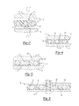
- FIG. 1 illustrates a top view of one configuration of the structural mounting insert according to the teachings of the present invention.
- FIG. 2 illustrates a cross sectional view of the structural insert shown in FIG. 1 with the addition of a first and a second member prior to joining according to the teachings of the present invention.
- FIG. 3 illustrates an enlarged view of the structural mounting insert shown in FIG. 2 .
- FIG. 4 illustrates the structural mounting insert shown in FIG. 3 after joining of the two components.
- FIG. 5 illustrates the structural mounting insert shown in FIG. 4 after activation of one available material according to the teachings of the present invention.
- FIG. 6 illustrates a cross sectional view similar to that shown in FIG. 5 , but instead taken through a mounting feature used to join the two members.
- FIG. 7 illustrates one an example of one application of the structural mounting insert according to the teachings of the present invention.
- FIG. 8 illustrates a top view of another configuration of the structural mounting insert according to the teachings of the present invention.
- FIG. 9 illustrates a cross section view of the structural insert shown in FIG. 8 .
- FIG. 10 illustrates an enlarged cross sectional view of FIG. 9 .
- FIG. 11 illustrates the structural mounting insert shown in FIG. 10 after joining of the two components.
- FIG. 12 illustrates the structural mounting insert shown in FIG. 11 after activation of one available material according to the teachings of the present invention.
- FIG. 13 illustrates a top view of another configuration of the structural mounting insert according to the teachings of the present invention.
- FIG. 14 illustrates a cross section view of the structural insert shown in FIG. 13 .
- FIG. 15 illustrates an enlarged cross sectional view of FIG. 14 .
- FIG. 16 illustrates the structural mounting insert shown in FIG. 15 after joining of the two components.
- FIG. 17 illustrates the structural mounting insert shown in FIG. 16 after activation of one available material according to the teachings of the present invention.
- the present invention is predicated upon methods and devices for positively mounting structural members while preventing or substantially limiting exposure of such members to environmental conditions possibly leading to corrosion.
- This is achieved through the use of an insert 10 placed between a first and second member 12 , 14 , respectively, prior to joining of the same.
- the insert includes a positive locating feature for maintaining a distance between the first and second member and a sealer that may be configured to fill open space between the first and second member, surround the insert and joining portions of the first and second members with the insert, or both.
- the sealer may be activatable, pliable or both to seal both the insert and the contacting portions 16 , 18 of the structural members from the surrounding environment.
- An additional advantage of the present invention is that it substantially limits or prevents torque fall off or the loosening of fasteners during thermal cycling or otherwise of the joined members. For example, during repeated cycles of warming and cooling typical sealing devices expand and contract due to the temperature change. Since the only spacer material used in these prior devices comprise the sealing material itself, it common that moisture enters the gaps formed by the seal during this thermal cycling. Also, it is common that prior sealing devices also undergo creep causing gaps to form which may be increased at elevated temperatures.
- the present invention overcomes these and other problems by providing a higher strength material for forming a gap or otherwise providing a spacer between the first and second members.
- the sealer of the insert then seals any gaps formed between the first and second members and surround the insert thereby substantially limiting or preventing corrosion of the connecting regions of the first and second members. This is because due to the combination of the high strength spacer and the sealing material sealing the edges of the insert, moisture is substantially limited or prevented from contacting the contacting points of the first and second member, which further prevents electrolytes from initiating corrosion since they originate from moisture.
- the insert 10 includes a first component 20 , 62 , 72 comprising a rigid material configured to resist deformation upon the application of force used to join the structural members.
- the insert also includes a second component 22 , which preferably encases or otherwise is attached or becomes attached to the first component.
- the second component is at least partially pliable so as to surround the insert and the contacting points or region of the structural members.
- the second component may be activated or otherwise deformed to cause sealing of the insert and contact points of the structural members thereby limiting or preventing exposure to corrosion driving components such as water, which can corrode the structural components.
- the insert includes a first component 20 comprising a flexible or rigid material that is configured to act as a spacer for the first and second members 12 , 14 .
- the first component is configured in strength to substantially resist deformation during attachment of the first and second members. Accordingly, it is contemplated that the first component is formed of a high strength material.
- Suitable materials that may be used to form the first component includes materials such as metal, plastic, ceramic, rubber or otherwise.
- the first component is formed of polymer.
- the first component is formed of metal (such as shim stock or otherwise) due to its flexibility (e.g. elasticity) and high strength for resisting plastic deformation.
- suitable metal materials include stainless steel, alloyed steels, coated or non-coated steel, galvanized steel, low or high carbon steel, cobalt, other metallic materials, the like or otherwise. Of course other specific materials are available such as those commonly used in textiles or otherwise.
- the first component 10 is formed with or otherwise includes a plurality of openings 24 formed therein for receiving at least a portion of the second component 22 .
- These opening may be formed using any available forming technique (such as molding or otherwise).
- the openings may be geometrical or non-geometrical (i.e. irregular) in shape.
- the geometry of the openings may vary depending upon the needs of a given application. Available shapes of the openings include circular, triangular, square or rectangular, hexagonal, octagonal, etc, or otherwise.
- the size of the openings 24 may vary for each application. It is contemplated that the openings includes a diameter less than 5 mm, 2 mm, 1 mm, 0.5 mm, 0.25 mm or smaller. Also, it is contemplated that the average diameter may be between 0.25 mm to 1 mm, between 0.5 mm to 1 mm, or otherwise. It should be appreciated that the shape and size of the openings may vary throughout the first component. However, in one preferred configuration the shape and size of the openings are consistent throughout the first component.
- the first component includes openings, and particularly where that component is a mesh material or otherwise, there are typically at least 10, more typically at least 150 and even more typically at least 300 openings per square inch, and/or less than about 3000, more typically less than about 800 and even more typically less than about 500 openings per square inch.
- the first component may be formed using different forming techniques.
- the first component may be woven or non-woven from one or a plurality of threads, wires or the like.
- the first component may comprise or be formed similar to that of a screen, or the like.
- the first component may be formed of a mesh material, such as metallic or polymer mesh, which results in the forming of openings 24 .
- Other techniques are available.
- the diameter of the threads or wires forming the first component may also vary for each application. It is contemplated that the thread or wires includes a diameter less than 10 mm, 5 mm, 2 mm, 1 mm or 0.5 mm or smaller. Also, it is contemplated that the average diameter of the threads or wires may be between 0.25 mm to 2 mm, between 0.5 mm to 1 mm, between 0.3 and 0.8 or otherwise. It should be appreciated that the shape and size of the wires may vary throughout the first component. However, in one preferred configuration the shape and size of the wires are consistent throughout the first component. Also, the cross-sectional shape of the wires may be circular, elliptical, square, rectangular, heptagon, hexagon, or otherwise.
- the first component may include a base member having one or more members, such as projections, extending from one or both sides to contact and spatially located the base member from the first and second member. This spatial location allows for placement of the second material between the base member and first or second member to cause sealing thereof.
- the base member may be formed of nearly any type of sheet metal or other material (e.g. sheet steel such as shim stock metal), or the like, and subsequently shaped to form a plurality of projections.
- the first component includes a base member 62 having a plurality of projections 64 extending therefrom.
- the projections may extend from one or both sides of the base member and are preferably spaced apart.
- the projections may form a symmetrical or asymmetrically pattern along the base member. Accordingly, it is contemplated that the projections may form one or more repeated patterns.
- the projections 64 may be attached or otherwise integrally formed with the base member to form a unitary structure.
- the projections may be formed using any available forming technique (such as molding, stamping, welding or otherwise). These projections may be geometrical or non-geometrical (i.e. irregular) in shape, wherein the geometry of the projections may vary depending upon the needs of a given application. Suitable shapes of the projections include circular, triangular, square or rectangular, hexagonal, octagonal, etc, or otherwise.
- the projections include a top surface 66 that is parallel to the base member and includes one or more (e.g. 2, 4 or otherwise) side members 68 for connecting the top surface with the based member. These side members may perpendicular with respect to the base member or top surfaces or may be diagonally orientated.
- the size of the projection may vary for each application. It is contemplated that the projection size (e.g. the top surface or the combination of the top surface and side members) may include a footprint area of about 0.25 mm 2 , 0.5 mm 2 , 1 mm 2 , 2 mm 2 , 5 mm 2 , 10 mm 2 , or more. It should be appreciated that the footprint size of the projection may vary throughout the first component. However, in one preferred configuration the foot print size of the projections are consistent throughout the first component.
- all or part of the base member and/or projections includes a layer of the second component 22 thereover.
- the second component may be located on one or both sides of the first component.
- the second component is located on both sides of the base member and on the projections.
- the first component includes a base member 72 having a plurality of projections 74 extending therefrom.
- the projections may extend from one or both sides of the base member and are preferably spaced apart.
- the projections may form a symmetrical or asymmetrically pattern along the base member. Accordingly, it is contemplated that the projections may form one or more repeated patterns.
- the projections 74 may be attached or otherwise integrally formed with the base member to form a unitary structure.
- the projections may be formed using any available forming technique (such as molding, stamping, welding or otherwise). These projections may be geometrical or non-geometrical (i.e. irregular) in shape, wherein the geometry of the projections may vary depending upon the needs of a given application. Suitable shapes of the projections include circular, triangular, square or rectangular, hexagonal, octagonal, etc, or otherwise.
- the projections include a top surface or portion 76 that is parallel to the base member and includes one or more side members 78 for connecting the top surface with the based member. These side members may perpendicular with respect to the base member or top surfaces or may be diagonally orientated. Still further, the side member may comprise an arcuate member. However, in one configuration, the combination of the top portion and side portion comprises a dome like structure
- the size of the projection may vary for each application. It is contemplated that the projection size (e.g. the top surface or the combination of the top surface and side members) may include a footprint area of about 0.25 mm 2 , 0.5 mm 2 , 1 mm 2 , 2 mm 2 , 5 mm 2 , 10 mm 2 or more. It should be appreciated that the footprint size of the projection may vary throughout the first component. However, in one preferred configuration the foot print size of the projections are consistent throughout the first component.
- all or part of the base member and/or projections includes a layer of the second component 22 thereover.
- the second component may be located on one or both sides of the first component.
- the second component is located on both sides of the base member and on the projections.
- first component may be coated, such as with a sealer or otherwise.
- the insert also includes a second component comprising a sealant material adapted to seal the insert and connecting regions of the first and second members.
- the second material may be configured to displace (e.g. elastically, plastically or both) during joining of a first and second member.
- the second component is provided with the first component during use or application to the first and/or second member.
- the second component is attached or otherwise joined with the first component to improve installation and reduce manufacturing cost.
- the second component substantially or entirely encases the first component.
- the second component may be applied to the first component using common techniques as described herein.
- the first component is dipped or otherwise immersed by the second component.
- the second component may be formed of any of the material components discussed herein. This includes sealant materials, materials to reduce noise vibration harshness, structural materials or otherwise. However, in a preferred configuration the material is configured to form a seal and prevent moisture (such as corrosive fluids of any kind, including water or otherwise) from entering between the second component and the first or second members.
- the second component may comprise a non-activatable material, an activatable material or a combination of both.
- the second component may comprise a non-activatable material, such as a typical gasket or otherwise used or capable to seal components and which undergoes little to no physical or chemical change upon application of energy.
- the second component may comprise an activatable material which does undergo physical and/or chemical change upon application of energy, as described herein. Still further, it is further contemplated that only a portion of the second component may be activatable.
- the second component comprises or includes an activatable material to cause sealing. More preferably, the second component comprises a heat activatable material configured to expand upon application of energy (such as heat or otherwise). In another preferred configuration, the second component comprises a non-expandable material and/or a non-activatable material, wherein the second material forms about the contact region of the first and second members and fills open space therebetween. Additional suitable materials and forming techniques for the second component are discussed below.
- the expandable material may be applied to the carrier using molding or shaping techniques, which may be automatic, semi-automatic or manual. Such techniques include blow molding, rotation molding, injection molding, compression molding casting, or otherwise.
- the expandable material is applied to the carrier through an extrusion (e.g. co-extrusion) process.
- the thickness of the second component may vary depending upon a number of factors such as whether and to what level the second component is activatable or expandable. The thickness may also be dependent upon the volume of open space between the first and second members, or about the first component, to be filled. Still further, the thickness may be based upon the pliability of the second component. Examples of suitable thicknesses include between about 0.5 to 10 mm or between about 1 to 5 mm or otherwise.
- the expandable material may be formed of several different materials.
- the member may utilize technology and processes for the forming and applying the expandable material such as those disclosed in U.S. Pat. Nos. 4,922,596, 4,978,562, 5,124,186, and 5,884,960 and commonly owned, co-pending U.S. application Ser. No. 09/502,686 filed Feb. 11, 2000 and Ser. No. 09/524,961 filed Mar. 14, 2000, and U.S. application Ser. No. 10/867,835, filed Jun. 15, 2004, all of which are expressly incorporated by reference for all purposes.
- the expandable material when used for reinforcement, form a high compressive strength and stiffness heat activated reinforcement material (e.g. foam) having foamable characteristics.
- the compressive strength modulus of the material is preferably greater than about 100 Mpa and more preferably greater than about 800 Mpa and still more preferably greater than about 1500 Mpa.
- the material may be generally dry to the touch or tacky and can be placed upon the first component or the like in any form of desired pattern, placement, or thickness, but is preferably of substantially uniform thickness.
- One exemplary expandable material is L-5204 structural foam available through L&L Products, Inc. of Romeo, Mich.
- tacky or non-tacky materials examples include L-2663, L-2610, L-2609, L-2701 or other similar material available through L&L Products, Inc. of Romeo, Mich.
- a preferred heat activated material is an expandable polymer or plastic, and preferably one that is foamable.
- a particularly preferred material is an epoxy-based structural foam.
- the structural foam may be an epoxy-based material, including an ethylene copolymer or terpolymer that may possess an alpha-olefin.
- the polymer is composed of two or three different monomers, i.e., small molecules with high chemical reactivity that are capable of linking up with similar molecules.
- a number of epoxy-based structural reinforcing or sealing foams are known in the art and may also be used to produce the structural foam.
- a typical structural foam includes a polymeric base material, such as an epoxy resin or ethylene-based polymer which, when compounded with appropriate ingredients (typically a blowing and curing agent), expands and cures in a reliable and predicable manner upon the application of heat or the occurrence of a particular ambient condition.
- the structural foam is usually initially processed as a flowable thermoplastic material before curing. Such a material will typically cross-link upon curing, which makes the material incapable of further flow.
- a preferred structural foam formulation is an epoxy-based material that is commercially available from L&L Products of Romeo, Mich., under the designations L5206, L5207, L5208, L5209.
- One advantage of the preferred structural foam materials over prior art materials is that the preferred materials can be processed in several ways.
- the preferred materials can be processed by injection molding, extrusion compression molding, overmolding onto a carrier or with a mini-applicator. This enables the formation and creation of part designs that exceed the capability of most prior art materials.
- the structural foam (in its uncured state) generally is dry or relatively free of tack to the touch and can easily be attached to the carrier member through fastening means which are well known in the art.
- the expandable material can be formed of other materials provided that the material selected is heat-activated or otherwise activated by an ambient condition (e.g. moisture, pressure, time or the like) and cures in a predictable and reliable manner under appropriate conditions for the selected application.
- an ambient condition e.g. moisture, pressure, time or the like
- One such material is the epoxy based resin disclosed in U.S. Pat. No. 6,131,897, the teachings of which are incorporated herein by reference, filed with the United States Patent and Trademark Office on Mar. 8, 1999 by the assignee of this application. See also, U.S. Pat. Nos. 5,766,719; 5,755,486; 5,575,526; and 5,932,680, (incorporated by reference).
- the desired characteristics of the expandable material include relatively high stiffness, high strength, high glass transition temperature (typically greater than 70 degrees Celsius), and adhesion durability properties. In this manner, the material does not generally interfere with the materials systems employed by automobile manufacturers.
- Exemplary materials include materials sold under product designation L5207 and L5208, which are commercially available from L & L Products, Romeo, Mich.
- the expandable material when used for reinforcement, is configured to expand to a volume that is between 110% and 500% more typically between 130% and 300% and even more typically between 150% and 250% of its original unexpended volume. It is also contemplated that when the system of the present invention is used for sealing or baffling, the expandable material may be designed to absorb or attenuate sound, block off and prevent passage of materials through a cavity or the like. As such, the expandable material may be configured to expand to a volume that is at least 200%, at least 400%, at least 800%, at least 1600% of even at least 3000% or its original unexpanded volume. Examples of such expandable material are discussed in U.S. application Ser. No. 10/867,835, filed Jun. 15, 2004, expressly incorporated by reference.
- the expandable material is a heat activated, thermally expanding material
- an important consideration involved with the selection and formulation of the material comprising the structural foam is the temperature at which a material reaction or expansion, and possibly curing, will take place.
- the material it is undesirable for the material to be reactive at room temperature or otherwise at the ambient temperature in a production line environment.
- the structural foam becomes reactive at higher processing temperatures, such as those encountered in an assembly plant, when the foam is processed along with the automobile components at elevated temperatures or at higher applied energy levels, e.g., during paint curing steps. While temperatures encountered in an automobile assembly operation may be in the range of about 148.89° C. to 204.44° C. (about 300° F.
- body and paint shop applications are commonly about 93.33° C. (about 200° F.) or slightly higher.
- higher temperatures may also be used during paint curing process (such as powder coat applications) or otherwise.
- the material becomes reactive at temperatures greater than about 120° C., or greater than about 150° C. or even greater than about 160° C. If needed, blowing agent activators can be incorporated into the composition to cause expansion at different temperatures outside the above ranges.
- the material may be cured in a powder coat paint cure operation. In such an operation, the material may be exposed to a temperature range between approximately 120°-230° C. with an exposure time between about 10 minutes to 60 minutes. Also, it is contemplated that the material may be cured in a precipitation hardening cure operation. In this operation, the material may be exposed to a temperature range between approximately 150°-230° C. with an exposure time between about 45 minutes to 8 hours.
- suitable expandable foams have a range of expansion ranging from approximately 0 to over 1000 percent.
- the level of expansion of the expandable material 30 may be increased to as high as 1500 percent or more.
- strength and stiffness are obtained from products that possess lower expansion.
- Some other possible materials for the expandable material include, but are not limited to, polyolefin materials, copolymers and terpolymers with at least one monomer type an alpha-olefin, phenol/formaldehyde materials, phenoxy materials, and polyurethane. See also, U.S. Pat. Nos. 5,266,133; 5,766,719; 5,755,486; 5,575,526; 5,932,680; and WO 00/27920 (PCT/US 99/24795) (all of which are expressly incorporated by reference). In general, the desired characteristics of the resulting material include relatively low glass transition point, and good adhesion durability properties.
- the material does not generally interfere with the materials systems employed by automotive or other vehicle manufacturers (e.g., motorcycle, bicycle, all terrain vehicles or otherwise). Moreover, it will withstand the processing conditions typically encountered in the manufacture of a vehicle, such as the e-coat priming, cleaning and degreasing and other coating processes, as well as the painting operations encountered in final vehicle assembly.
- the expandable material is provided in an encapsulated or partially encapsulated form, which may comprise a pellet, which includes an expandable foamable material, encapsulated or partially encapsulated in an adhesive shell.
- an encapsulated or partially encapsulated form which may comprise a pellet, which includes an expandable foamable material, encapsulated or partially encapsulated in an adhesive shell.
- preformed patterns may also be employed such as those made by extruding a sheet (having a flat or contoured surface) and then die cutting it according to a predetermined configuration in accordance with the chosen structure, carrier member or the like, and applying it to thereto.
- system may be employed in combination with or as a component of a conventional sound blocking baffle, or a vehicle structural reinforcement system, such as is disclosed in commonly owned co-pending U.S. application Ser. Nos. 09/524,961 or 09/502,686 (hereby incorporated by reference).
- the material of the expandable material could be delivered and placed into contact with the assembly members, through a variety of delivery systems which include, but are not limited to, a mechanical snap fit assembly, extrusion techniques commonly known in the art as well as a mini-applicator technique as in accordance with the teachings of commonly owned U.S. Pat. No. 5,358,397 (“Apparatus For Extruding Flowable Materials”), hereby expressly incorporated by reference.
- the material or medium is at least partially coated with an active polymer having damping characteristics or other heat activated polymer, (e.g., a formable hot melt adhesive based polymer or an expandable structural foam, examples of which include olefinic polymers, vinyl polymers, thermoplastic rubber-containing polymers, epoxies, urethanes or the like) wherein the framable or expandable material can be snap-fit onto the chosen surface or substrate; placed into beads or pellets for placement along the chosen substrate or member by means of extrusion; placed along the substrate through the use of baffle technology; a die-cast application according to teachings that are well known in the art; pumpable application systems which could include the use of a baffle and bladder system; and sprayable applications.
- an active polymer having damping characteristics or other heat activated polymer e.g., a formable hot melt adhesive based polymer or an expandable structural foam, examples of which include olefinic polymers, vinyl polymers, thermoplastic rubber-containing polymers, ep
- the second material may be non-activatable and/or non-expandable.
- the second material plastically deforms to surround the insert and the contact region of the first and second insert to cause sealing of the same.
- the second material may comprise a gasket.
- the second material may comprise any suitable gasket used for sealing joined components.
- the shape and size of the insert may vary between applications. It is contemplated that the insert may be generally square or rectangular in shape. However, other shapes include circular, elliptical, heptagonal, hexagons, etc, or otherwise, including regular or irregular shapes are contemplated.
- the thickness of the insert may also vary depending upon the application and application of force. However, the thickness may be less than 10 mm, 5 mm, 2 mm or less. Accordingly, it is contemplated that the insert has a continuous thickness in the range of 1 mm to 10 mm or even 2 mm to 5 mm or otherwise.
- FIGS. 2-6 , FIGS. 8-12 and FIGS. 13-17 three examples of use of the insert of the present invention are shown, respectively.
- the present invention is particularly suited for fastening (e.g. bolted or otherwise) systems for joining and maintaining a distance between two or more members.
- the insert as described herein, is placed between a first and second member 12 , 14 prior to attachment of the same.
- the first and second members are then brought together and an application of force ‘F’ is applied, through the used of fastening devices, or otherwise.
- openings may be formed between the first component and the first and second members 12 , 14 . These openings may be partially or completely filled by the second component before activation of the second material, after activation of the second material or both.
- the generated torque formed during attachment of the first and second members may cause the second material located over the first component to displace and partially or completely fill the open spaces prior to activation.
- the open spaces may be additionally filled with an expanding second material.
- the second component comprising the sealing material is displaced into the openings or along the projections formed by the first component 20 , 62 , 72 and/or outside of the end portion of the first component. This displacement continues until the first and second member contact the first component, which may include contact with the projections. At this point the first component acts as a spacer to form and maintain a substantially continuous gap between the first and second member.
- the first component is suitable in strength so as to provide a reactionary force to the applied force without substantial deformation.
- the projections 64 , 74 may be configured to deform towards the surface of the first component.
- the second component may be activated, which in one preferred configuration causes the second component to expand and fill any openings formed by the first component or open spaces formed between the projections. Also, it should be appreciated that the material outside of the first component also expands to form a seal about the entirety of the first component. At this point, the contact regions of the first and second members and the insert are entirely sealed from the surrounding environment.
- the expandable material fills the surrounding area where a fastener extends therethrough to substantially limit or prevent moisture from entering therein.
- a hinge assembly 30 is provided for mounting a door component to a frame member of an automotive vehicle.
- the hinge includes a first hinge portion 32 including a first mounting feature 34 for attachment to a vehicle door.
- the first hinge portion includes: i) a planar mounting surface 36 including a plurality of holes 38 formed therein for receiving one or more mechanical fasteners used for mounting the first hinge portion to the vehicle door, ii) arms 40 extending from opposite sides of the planar mounting surface, the arms including a first aperture 42 extending through the arms for forming a portion of a pivotal connection.
- the hinge also includes a second hinge portion 44 including a second mounting feature 46 for attachment to a vehicle frame member.
- the second hinge portion includes a planar mounting surface 48 including: i) a plurality of fasteners 50 extending therefrom for mounting the first hinge portion to the vehicle frame member, ii) arms 62 extending from opposite sides of the planar mounting surface, the arms including a second aperture 54 extending through the arms for forming a portion of the pivotal connection.
- the hinge further includes a pivotal connection for rotatable attachment of the first hinge portion to the second hinge portion, the pivotal connection formed of the first aperture, the second aperture and a pin 56 extending through the first and second aperture, wherein the are arms of the first and second hinge portion are located adjacent one another and are adapted to rotate with respect to one another, wherein the pivotal connection further includes one or more retaining features 58 from temporarily or permanently preventing removal of the pin from the first and second apertures.
- the hinge further includes a structural mounting insert 10 as described herein. As shown, the insert includes openings 60 formed therein for receiving mounting feature of the second hinge portion. These openings may vary between applications.
- the reinforcing system of the present invention may be utilized in various aspects of structural reinforcement, particularly in the transportation industry for motorcycles, bicycles, automotive vehicles, boats, trains, or otherwise.
- the reinforcing system of the present invention may be used for applications where metal components are joined together and wherein such components are commonly exposed to moisture.
- the insert of the present invention provides solid mounting of such components while protecting the same from corrosion. Additional components for which the present invention can be useful include, without limitation front and rear bumper systems, lift gates, underbody reinforcements or the like.
- the reinforcing system of the present invention may be used in body repair shops, in general assembly plants, or otherwise. Not only does the reinforcing system provide improved attachment for two or more components during original manufacturing, but also provides improved attachment for components which integrity (e.g. strength or otherwise) has be jeopardized, such as during an accident.
- integrity e.g. strength or otherwise
- an individual, machine or combination thereof can fasten (e.g., bolt, screw or otherwise affix) two or more surfaces or members together and limit or prevent corrosion and/or loosening of the fasteners (e.g., torque fall off).
- the limiting or prevention of fastener loosening can be accomplished, in one preferred embodiment, by drawing or forcing together or tightening of the surfaces or members together (e.g., via the fasteners until contact (e.g., metal to metal contact) is achieved between the members or surfaces and the first component.
- the surfaces or member can continue to be drawn or forced together to produce a compressive force upon the first component that does not experience an undesirably high amount of creep that can be caused by time passing and/or temperature changes. In this manner, force is maintained on the fastener thereby inhibiting or preventing fastener loosening (e.g., torque fall off).
- the present invention can then limit or eliminate checks and re-checks of fastener tightness or torque that might otherwise be needed and can limit or eliminate the need for re-tightening of such fasteners.
Abstract
A structural mounting insert for sealing between and/or adhering to surfaces of members is described. The insert includes a base member and activatable material about the base material.
Description
This application is a continuation of Ser. No. 13/185,589, filed on Jul. 19, 2011, which is a continuation of Ser. No. 11/969,389, filed on Jan. 4, 2008, which claims the benefit of U.S. Provisional Application Ser. No. 60/887,287 filed Jan. 30, 2007 and U.S. Provisional Application Ser. No. 60/951,327 filed Jul. 23, 2007 all of which are incorporated herein by reference for all purposes.
The present invention relates to a methods and devices for the protection of two or more joined components from corrosion, loosening of fasteners (e.g., torque fall off) or both.
For many years, industry has developed sealing materials and structural materials that can be located between surfaces of members for limiting exposure of those surfaces to ambient environments and/or for assisting in connecting the surfaces together. Such materials, however, suffer from drawbacks. As one example, expansion/contraction characteristics of the materials during exposure to temperature variances can limit the ability of the materials to seal and/or can degrade materials. As another example, such materials can limit that ability of members to be attached to each other or have a limited ability to enhance the attachment of members to each other. Thus, the present invention is provides an insert that acts as a seal, a structural adhesive material, both or the like wherein the material at least assists in overcoming one of the aforementioned drawbacks or other drawbacks.
Accordingly, there is disclosed a structural mounting insert usable during mounting of a first and second member. The structural mounting insert is typically placed between and configured to seal the connection regions of the first and second member from the surrounding environment. The structural mounting insert typically includes a base member (e.g., a member formed of structural mesh material) shaped to correspond to the shape of the connection region between the first and second member and a heat activatable material encased over at least a portion of the structural mesh material. In one embodiment, the base member can have a plurality of opening extending therethrough and the openings can be equally shaped and spaced if desired. The heat activatable material can be located within the openings and also is typically formed of a pliable material. Upon mounting of the first and second member, the heat activatable material is typically displaced to allow direct contact between the base member and both the first and second member. Moreover, upon application of heat, the heat activatable material typically expands to fill the openings formed through the base member and to seal the base member and connection regions of the first and second members.
The present invention is predicated upon methods and devices for positively mounting structural members while preventing or substantially limiting exposure of such members to environmental conditions possibly leading to corrosion. Referring to the drawings, this is achieved through the use of an insert 10 placed between a first and second member 12, 14, respectively, prior to joining of the same. The insert includes a positive locating feature for maintaining a distance between the first and second member and a sealer that may be configured to fill open space between the first and second member, surround the insert and joining portions of the first and second members with the insert, or both. The sealer may be activatable, pliable or both to seal both the insert and the contacting portions 16, 18 of the structural members from the surrounding environment.
An additional advantage of the present invention is that it substantially limits or prevents torque fall off or the loosening of fasteners during thermal cycling or otherwise of the joined members. For example, during repeated cycles of warming and cooling typical sealing devices expand and contract due to the temperature change. Since the only spacer material used in these prior devices comprise the sealing material itself, it common that moisture enters the gaps formed by the seal during this thermal cycling. Also, it is common that prior sealing devices also undergo creep causing gaps to form which may be increased at elevated temperatures.
The present invention overcomes these and other problems by providing a higher strength material for forming a gap or otherwise providing a spacer between the first and second members. The sealer of the insert then seals any gaps formed between the first and second members and surround the insert thereby substantially limiting or preventing corrosion of the connecting regions of the first and second members. This is because due to the combination of the high strength spacer and the sealing material sealing the edges of the insert, moisture is substantially limited or prevented from contacting the contacting points of the first and second member, which further prevents electrolytes from initiating corrosion since they originate from moisture.
Generally, the insert 10 includes a first component 20, 62, 72 comprising a rigid material configured to resist deformation upon the application of force used to join the structural members. The insert also includes a second component 22, which preferably encases or otherwise is attached or becomes attached to the first component. The second component is at least partially pliable so as to surround the insert and the contacting points or region of the structural members.
Upon joining of the first and second structural member, the second component may be activated or otherwise deformed to cause sealing of the insert and contact points of the structural members thereby limiting or preventing exposure to corrosion driving components such as water, which can corrode the structural components.
It should be appreciated that the foregoing is just one of many examples and advantages of the present invention and the follow description provides, implicitly and/or explicitly, other examples and advantages of the present invention, which are further supported by the drawings.
First Component—Spacer Material
The insert includes a first component 20 comprising a flexible or rigid material that is configured to act as a spacer for the first and second members 12, 14. However, preferably, the first component is configured in strength to substantially resist deformation during attachment of the first and second members. Accordingly, it is contemplated that the first component is formed of a high strength material.
Suitable materials that may be used to form the first component includes materials such as metal, plastic, ceramic, rubber or otherwise. In one configuration the first component is formed of polymer. In another preferred configuration, the first component is formed of metal (such as shim stock or otherwise) due to its flexibility (e.g. elasticity) and high strength for resisting plastic deformation. Examples of suitable metal materials include stainless steel, alloyed steels, coated or non-coated steel, galvanized steel, low or high carbon steel, cobalt, other metallic materials, the like or otherwise. Of course other specific materials are available such as those commonly used in textiles or otherwise.
In a first exemplary configuration, as shown in FIGS. 1-6 , the first component 10 is formed with or otherwise includes a plurality of openings 24 formed therein for receiving at least a portion of the second component 22. These opening may be formed using any available forming technique (such as molding or otherwise). The openings may be geometrical or non-geometrical (i.e. irregular) in shape. The geometry of the openings may vary depending upon the needs of a given application. Available shapes of the openings include circular, triangular, square or rectangular, hexagonal, octagonal, etc, or otherwise.
Also the size of the openings 24 may vary for each application. It is contemplated that the openings includes a diameter less than 5 mm, 2 mm, 1 mm, 0.5 mm, 0.25 mm or smaller. Also, it is contemplated that the average diameter may be between 0.25 mm to 1 mm, between 0.5 mm to 1 mm, or otherwise. It should be appreciated that the shape and size of the openings may vary throughout the first component. However, in one preferred configuration the shape and size of the openings are consistent throughout the first component. When the first component includes openings, and particularly where that component is a mesh material or otherwise, there are typically at least 10, more typically at least 150 and even more typically at least 300 openings per square inch, and/or less than about 3000, more typically less than about 800 and even more typically less than about 500 openings per square inch.
The first component may be formed using different forming techniques. The first component may be woven or non-woven from one or a plurality of threads, wires or the like. The first component may comprise or be formed similar to that of a screen, or the like. With regards to woven configurations, the first component may be formed of a mesh material, such as metallic or polymer mesh, which results in the forming of openings 24. Other techniques are available.
The diameter of the threads or wires forming the first component may also vary for each application. It is contemplated that the thread or wires includes a diameter less than 10 mm, 5 mm, 2 mm, 1 mm or 0.5 mm or smaller. Also, it is contemplated that the average diameter of the threads or wires may be between 0.25 mm to 2 mm, between 0.5 mm to 1 mm, between 0.3 and 0.8 or otherwise. It should be appreciated that the shape and size of the wires may vary throughout the first component. However, in one preferred configuration the shape and size of the wires are consistent throughout the first component. Also, the cross-sectional shape of the wires may be circular, elliptical, square, rectangular, heptagon, hexagon, or otherwise.
In a second and third configuration of the first component, as discussed below in more detail, it is contemplated that the first component may include a base member having one or more members, such as projections, extending from one or both sides to contact and spatially located the base member from the first and second member. This spatial location allows for placement of the second material between the base member and first or second member to cause sealing thereof. In one configuration, the base member may be formed of nearly any type of sheet metal or other material (e.g. sheet steel such as shim stock metal), or the like, and subsequently shaped to form a plurality of projections.
In the second exemplary configuration, as shown in FIGS. 8-12 , the first component includes a base member 62 having a plurality of projections 64 extending therefrom. The projections may extend from one or both sides of the base member and are preferably spaced apart. The projections may form a symmetrical or asymmetrically pattern along the base member. Accordingly, it is contemplated that the projections may form one or more repeated patterns.
The projections 64 may be attached or otherwise integrally formed with the base member to form a unitary structure. The projections may be formed using any available forming technique (such as molding, stamping, welding or otherwise). These projections may be geometrical or non-geometrical (i.e. irregular) in shape, wherein the geometry of the projections may vary depending upon the needs of a given application. Suitable shapes of the projections include circular, triangular, square or rectangular, hexagonal, octagonal, etc, or otherwise. In one preferred configuration, the projections include a top surface 66 that is parallel to the base member and includes one or more (e.g. 2, 4 or otherwise) side members 68 for connecting the top surface with the based member. These side members may perpendicular with respect to the base member or top surfaces or may be diagonally orientated.
The size of the projection may vary for each application. It is contemplated that the projection size (e.g. the top surface or the combination of the top surface and side members) may include a footprint area of about 0.25 mm2, 0.5 mm2, 1 mm2, 2 mm2, 5 mm2, 10 mm2, or more. It should be appreciated that the footprint size of the projection may vary throughout the first component. However, in one preferred configuration the foot print size of the projections are consistent throughout the first component.
Preferably, all or part of the base member and/or projections includes a layer of the second component 22 thereover. The second component may be located on one or both sides of the first component. However, in one preferred configuration, the second component is located on both sides of the base member and on the projections.
In the third exemplary configuration, as shown in FIGS.13-17 , the first component includes a base member 72 having a plurality of projections 74 extending therefrom. The projections may extend from one or both sides of the base member and are preferably spaced apart. The projections may form a symmetrical or asymmetrically pattern along the base member. Accordingly, it is contemplated that the projections may form one or more repeated patterns.
The projections 74 may be attached or otherwise integrally formed with the base member to form a unitary structure. The projections may be formed using any available forming technique (such as molding, stamping, welding or otherwise). These projections may be geometrical or non-geometrical (i.e. irregular) in shape, wherein the geometry of the projections may vary depending upon the needs of a given application. Suitable shapes of the projections include circular, triangular, square or rectangular, hexagonal, octagonal, etc, or otherwise. In one preferred configuration, the projections include a top surface or portion 76 that is parallel to the base member and includes one or more side members 78 for connecting the top surface with the based member. These side members may perpendicular with respect to the base member or top surfaces or may be diagonally orientated. Still further, the side member may comprise an arcuate member. However, in one configuration, the combination of the top portion and side portion comprises a dome like structure
The size of the projection may vary for each application. It is contemplated that the projection size (e.g. the top surface or the combination of the top surface and side members) may include a footprint area of about 0.25 mm2, 0.5 mm2, 1 mm2, 2 mm2, 5 mm2, 10 mm2 or more. It should be appreciated that the footprint size of the projection may vary throughout the first component. However, in one preferred configuration the foot print size of the projections are consistent throughout the first component.
Preferably, all or part of the base member and/or projections includes a layer of the second component 22 thereover. The second component may be located on one or both sides of the first component. However, in one preferred configuration, the second component is located on both sides of the base member and on the projections.
With respect to the different embodiments contained herein, or otherwise, it is contemplated that all or a portion of the first component may be coated, such as with a sealer or otherwise.
Second Component—Sealant Material
The insert also includes a second component comprising a sealant material adapted to seal the insert and connecting regions of the first and second members. The second material may be configured to displace (e.g. elastically, plastically or both) during joining of a first and second member. The second component is provided with the first component during use or application to the first and/or second member. Preferably, the second component is attached or otherwise joined with the first component to improve installation and reduce manufacturing cost.
In one configuration, the second component substantially or entirely encases the first component. The second component may be applied to the first component using common techniques as described herein. However, in one preferred configuration, the first component is dipped or otherwise immersed by the second component.
The second component may be formed of any of the material components discussed herein. This includes sealant materials, materials to reduce noise vibration harshness, structural materials or otherwise. However, in a preferred configuration the material is configured to form a seal and prevent moisture (such as corrosive fluids of any kind, including water or otherwise) from entering between the second component and the first or second members.
The second component may comprise a non-activatable material, an activatable material or a combination of both. For example, the second component may comprise a non-activatable material, such as a typical gasket or otherwise used or capable to seal components and which undergoes little to no physical or chemical change upon application of energy. Alternatively, the second component may comprise an activatable material which does undergo physical and/or chemical change upon application of energy, as described herein. Still further, it is further contemplated that only a portion of the second component may be activatable.
In one preferred configuration, the second component comprises or includes an activatable material to cause sealing. More preferably, the second component comprises a heat activatable material configured to expand upon application of energy (such as heat or otherwise). In another preferred configuration, the second component comprises a non-expandable material and/or a non-activatable material, wherein the second material forms about the contact region of the first and second members and fills open space therebetween. Additional suitable materials and forming techniques for the second component are discussed below.
The expandable material may be applied to the carrier using molding or shaping techniques, which may be automatic, semi-automatic or manual. Such techniques include blow molding, rotation molding, injection molding, compression molding casting, or otherwise. In one highly preferred configuration, the expandable material is applied to the carrier through an extrusion (e.g. co-extrusion) process.
The thickness of the second component may vary depending upon a number of factors such as whether and to what level the second component is activatable or expandable. The thickness may also be dependent upon the volume of open space between the first and second members, or about the first component, to be filled. Still further, the thickness may be based upon the pliability of the second component. Examples of suitable thicknesses include between about 0.5 to 10 mm or between about 1 to 5 mm or otherwise.
The expandable material may be formed of several different materials. Generally speaking, the member may utilize technology and processes for the forming and applying the expandable material such as those disclosed in U.S. Pat. Nos. 4,922,596, 4,978,562, 5,124,186, and 5,884,960 and commonly owned, co-pending U.S. application Ser. No. 09/502,686 filed Feb. 11, 2000 and Ser. No. 09/524,961 filed Mar. 14, 2000, and U.S. application Ser. No. 10/867,835, filed Jun. 15, 2004, all of which are expressly incorporated by reference for all purposes. Typically, when used for reinforcement, the expandable material form a high compressive strength and stiffness heat activated reinforcement material (e.g. foam) having foamable characteristics. For example, the compressive strength modulus of the material is preferably greater than about 100 Mpa and more preferably greater than about 800 Mpa and still more preferably greater than about 1500 Mpa.
The material may be generally dry to the touch or tacky and can be placed upon the first component or the like in any form of desired pattern, placement, or thickness, but is preferably of substantially uniform thickness. One exemplary expandable material is L-5204 structural foam available through L&L Products, Inc. of Romeo, Mich.
Examples of other suitable tacky or non-tacky materials include L-2663, L-2610, L-2609, L-2701 or other similar material available through L&L Products, Inc. of Romeo, Mich.
Though other heat-activated materials are possible for the expandable material, a preferred heat activated material is an expandable polymer or plastic, and preferably one that is foamable. A particularly preferred material is an epoxy-based structural foam. For example, and without limitation, the structural foam may be an epoxy-based material, including an ethylene copolymer or terpolymer that may possess an alpha-olefin. As a copolymer or terpolymer, the polymer is composed of two or three different monomers, i.e., small molecules with high chemical reactivity that are capable of linking up with similar molecules.
A number of epoxy-based structural reinforcing or sealing foams are known in the art and may also be used to produce the structural foam. A typical structural foam includes a polymeric base material, such as an epoxy resin or ethylene-based polymer which, when compounded with appropriate ingredients (typically a blowing and curing agent), expands and cures in a reliable and predicable manner upon the application of heat or the occurrence of a particular ambient condition. From a chemical standpoint for a thermally-activated material or a thermoset material, the structural foam is usually initially processed as a flowable thermoplastic material before curing. Such a material will typically cross-link upon curing, which makes the material incapable of further flow.
An example of a preferred structural foam formulation is an epoxy-based material that is commercially available from L&L Products of Romeo, Mich., under the designations L5206, L5207, L5208, L5209. One advantage of the preferred structural foam materials over prior art materials is that the preferred materials can be processed in several ways. The preferred materials can be processed by injection molding, extrusion compression molding, overmolding onto a carrier or with a mini-applicator. This enables the formation and creation of part designs that exceed the capability of most prior art materials. In one preferred embodiment, the structural foam (in its uncured state) generally is dry or relatively free of tack to the touch and can easily be attached to the carrier member through fastening means which are well known in the art.
While the preferred materials for fabricating the expandable material have been disclosed, the expandable material can be formed of other materials provided that the material selected is heat-activated or otherwise activated by an ambient condition (e.g. moisture, pressure, time or the like) and cures in a predictable and reliable manner under appropriate conditions for the selected application. One such material is the epoxy based resin disclosed in U.S. Pat. No. 6,131,897, the teachings of which are incorporated herein by reference, filed with the United States Patent and Trademark Office on Mar. 8, 1999 by the assignee of this application. See also, U.S. Pat. Nos. 5,766,719; 5,755,486; 5,575,526; and 5,932,680, (incorporated by reference). In general, the desired characteristics of the expandable material include relatively high stiffness, high strength, high glass transition temperature (typically greater than 70 degrees Celsius), and adhesion durability properties. In this manner, the material does not generally interfere with the materials systems employed by automobile manufacturers. Exemplary materials include materials sold under product designation L5207 and L5208, which are commercially available from L & L Products, Romeo, Mich.
Typically, when used for reinforcement, the expandable material is configured to expand to a volume that is between 110% and 500% more typically between 130% and 300% and even more typically between 150% and 250% of its original unexpended volume. It is also contemplated that when the system of the present invention is used for sealing or baffling, the expandable material may be designed to absorb or attenuate sound, block off and prevent passage of materials through a cavity or the like. As such, the expandable material may be configured to expand to a volume that is at least 200%, at least 400%, at least 800%, at least 1600% of even at least 3000% or its original unexpanded volume. Examples of such expandable material are discussed in U.S. application Ser. No. 10/867,835, filed Jun. 15, 2004, expressly incorporated by reference.
In applications where the expandable material is a heat activated, thermally expanding material, an important consideration involved with the selection and formulation of the material comprising the structural foam is the temperature at which a material reaction or expansion, and possibly curing, will take place. For instance, in most applications, it is undesirable for the material to be reactive at room temperature or otherwise at the ambient temperature in a production line environment. More typically, the structural foam becomes reactive at higher processing temperatures, such as those encountered in an assembly plant, when the foam is processed along with the automobile components at elevated temperatures or at higher applied energy levels, e.g., during paint curing steps. While temperatures encountered in an automobile assembly operation may be in the range of about 148.89° C. to 204.44° C. (about 300° F. to 400° F.), body and paint shop applications are commonly about 93.33° C. (about 200° F.) or slightly higher. Similarly, during manufacturing of other transportation device (e.g., bicycle, motorcycles, all terrain vehicles or otherwise), higher temperatures may also be used during paint curing process (such as powder coat applications) or otherwise. In one configuration, the material becomes reactive at temperatures greater than about 120° C., or greater than about 150° C. or even greater than about 160° C. If needed, blowing agent activators can be incorporated into the composition to cause expansion at different temperatures outside the above ranges.
By specific example, it is contemplated that the material may be cured in a powder coat paint cure operation. In such an operation, the material may be exposed to a temperature range between approximately 120°-230° C. with an exposure time between about 10 minutes to 60 minutes. Also, it is contemplated that the material may be cured in a precipitation hardening cure operation. In this operation, the material may be exposed to a temperature range between approximately 150°-230° C. with an exposure time between about 45 minutes to 8 hours.
Generally, suitable expandable foams have a range of expansion ranging from approximately 0 to over 1000 percent. The level of expansion of the expandable material 30 may be increased to as high as 1500 percent or more. Typically, strength and stiffness are obtained from products that possess lower expansion.
Some other possible materials for the expandable material include, but are not limited to, polyolefin materials, copolymers and terpolymers with at least one monomer type an alpha-olefin, phenol/formaldehyde materials, phenoxy materials, and polyurethane. See also, U.S. Pat. Nos. 5,266,133; 5,766,719; 5,755,486; 5,575,526; 5,932,680; and WO 00/27920 (PCT/US 99/24795) (all of which are expressly incorporated by reference). In general, the desired characteristics of the resulting material include relatively low glass transition point, and good adhesion durability properties. In this manner, the material does not generally interfere with the materials systems employed by automotive or other vehicle manufacturers (e.g., motorcycle, bicycle, all terrain vehicles or otherwise). Moreover, it will withstand the processing conditions typically encountered in the manufacture of a vehicle, such as the e-coat priming, cleaning and degreasing and other coating processes, as well as the painting operations encountered in final vehicle assembly.
In another embodiment, the expandable material is provided in an encapsulated or partially encapsulated form, which may comprise a pellet, which includes an expandable foamable material, encapsulated or partially encapsulated in an adhesive shell. An example of one such system is disclosed in commonly owned, co-pending U.S. application Ser. No. 09/524,298 (“Expandable Pre-Formed Plug”), hereby incorporated by reference.
In addition, as discussed previously, preformed patterns may also be employed such as those made by extruding a sheet (having a flat or contoured surface) and then die cutting it according to a predetermined configuration in accordance with the chosen structure, carrier member or the like, and applying it to thereto.
The skilled artisan will appreciate that the system may be employed in combination with or as a component of a conventional sound blocking baffle, or a vehicle structural reinforcement system, such as is disclosed in commonly owned co-pending U.S. application Ser. Nos. 09/524,961 or 09/502,686 (hereby incorporated by reference).
It is contemplated that the material of the expandable material could be delivered and placed into contact with the assembly members, through a variety of delivery systems which include, but are not limited to, a mechanical snap fit assembly, extrusion techniques commonly known in the art as well as a mini-applicator technique as in accordance with the teachings of commonly owned U.S. Pat. No. 5,358,397 (“Apparatus For Extruding Flowable Materials”), hereby expressly incorporated by reference. In this non-limiting embodiment, the material or medium is at least partially coated with an active polymer having damping characteristics or other heat activated polymer, (e.g., a formable hot melt adhesive based polymer or an expandable structural foam, examples of which include olefinic polymers, vinyl polymers, thermoplastic rubber-containing polymers, epoxies, urethanes or the like) wherein the framable or expandable material can be snap-fit onto the chosen surface or substrate; placed into beads or pellets for placement along the chosen substrate or member by means of extrusion; placed along the substrate through the use of baffle technology; a die-cast application according to teachings that are well known in the art; pumpable application systems which could include the use of a baffle and bladder system; and sprayable applications.
In another preferred configuration, as previously mentioned, the second material may be non-activatable and/or non-expandable. In this configuration, it is contemplated that upon application of force, and optionally activation, the second material plastically deforms to surround the insert and the contact region of the first and second insert to cause sealing of the same. Accordingly, in one configuration, the second material may comprise a gasket. For example, the second material may comprise any suitable gasket used for sealing joined components.
The shape and size of the insert may vary between applications. It is contemplated that the insert may be generally square or rectangular in shape. However, other shapes include circular, elliptical, heptagonal, hexagons, etc, or otherwise, including regular or irregular shapes are contemplated. The thickness of the insert may also vary depending upon the application and application of force. However, the thickness may be less than 10 mm, 5 mm, 2 mm or less. Accordingly, it is contemplated that the insert has a continuous thickness in the range of 1 mm to 10 mm or even 2 mm to 5 mm or otherwise.
Method of Use
Referring to FIGS. 2-6 , FIGS. 8-12 and FIGS. 13-17 , three examples of use of the insert of the present invention are shown, respectively. The present invention is particularly suited for fastening (e.g. bolted or otherwise) systems for joining and maintaining a distance between two or more members. The insert, as described herein, is placed between a first and second member 12, 14 prior to attachment of the same. The first and second members are then brought together and an application of force ‘F’ is applied, through the used of fastening devices, or otherwise.
As shown in the three examples, openings may be formed between the first component and the first and second members 12, 14. These openings may be partially or completely filled by the second component before activation of the second material, after activation of the second material or both. For example, during attachment of the first and second member, the generated torque formed during attachment of the first and second members may cause the second material located over the first component to displace and partially or completely fill the open spaces prior to activation. Alternatively, or in addition to pre-activation filling of the open spaces, during activation of the second material the open spaces may be additionally filled with an expanding second material.
Referring to FIGS. 4 , 11 and 16, as the force is increased, the second component comprising the sealing material is displaced into the openings or along the projections formed by the first component 20, 62, 72 and/or outside of the end portion of the first component. This displacement continues until the first and second member contact the first component, which may include contact with the projections. At this point the first component acts as a spacer to form and maintain a substantially continuous gap between the first and second member. As previously mentioned, the first component is suitable in strength so as to provide a reactionary force to the applied force without substantial deformation. However, with respect to the second and third embodiments of the first component 62, 72, the projections 64, 74 may be configured to deform towards the surface of the first component.
As shown in FIGS. 5 , 12 and 17 with the first and second members attached, the second component may be activated, which in one preferred configuration causes the second component to expand and fill any openings formed by the first component or open spaces formed between the projections. Also, it should be appreciated that the material outside of the first component also expands to form a seal about the entirety of the first component. At this point, the contact regions of the first and second members and the insert are entirely sealed from the surrounding environment.
With reference to FIG. 6 , were openings are formed through the insert, the expandable material fills the surrounding area where a fastener extends therethrough to substantially limit or prevent moisture from entering therein.
One Specific Example
Referring to FIG. 7 , one non-limiting example, and use, of the structural mounting insert of the present invention is shown. In this example, it should be appreciated that any of the embodiments (e.g. first components or otherwise) may used. In this configuration a hinge assembly 30 is provided for mounting a door component to a frame member of an automotive vehicle. The hinge includes a first hinge portion 32 including a first mounting feature 34 for attachment to a vehicle door. The first hinge portion includes: i) a planar mounting surface 36 including a plurality of holes 38 formed therein for receiving one or more mechanical fasteners used for mounting the first hinge portion to the vehicle door, ii) arms 40 extending from opposite sides of the planar mounting surface, the arms including a first aperture 42 extending through the arms for forming a portion of a pivotal connection.
The hinge also includes a second hinge portion 44 including a second mounting feature 46 for attachment to a vehicle frame member. The second hinge portion includes a planar mounting surface 48 including: i) a plurality of fasteners 50 extending therefrom for mounting the first hinge portion to the vehicle frame member, ii) arms 62 extending from opposite sides of the planar mounting surface, the arms including a second aperture 54 extending through the arms for forming a portion of the pivotal connection.
The hinge further includes a pivotal connection for rotatable attachment of the first hinge portion to the second hinge portion, the pivotal connection formed of the first aperture, the second aperture and a pin 56 extending through the first and second aperture, wherein the are arms of the first and second hinge portion are located adjacent one another and are adapted to rotate with respect to one another, wherein the pivotal connection further includes one or more retaining features 58 from temporarily or permanently preventing removal of the pin from the first and second apertures.
The hinge further includes a structural mounting insert 10 as described herein. As shown, the insert includes openings 60 formed therein for receiving mounting feature of the second hinge portion. These openings may vary between applications.
Other Applications
The reinforcing system of the present invention may be utilized in various aspects of structural reinforcement, particularly in the transportation industry for motorcycles, bicycles, automotive vehicles, boats, trains, or otherwise. In one particularly advantageous application, the reinforcing system of the present invention may be used for applications where metal components are joined together and wherein such components are commonly exposed to moisture. In these configurations, the insert of the present invention provides solid mounting of such components while protecting the same from corrosion. Additional components for which the present invention can be useful include, without limitation front and rear bumper systems, lift gates, underbody reinforcements or the like.
It should be appreciated that the reinforcing system of the present invention may be used in body repair shops, in general assembly plants, or otherwise. Not only does the reinforcing system provide improved attachment for two or more components during original manufacturing, but also provides improved attachment for components which integrity (e.g. strength or otherwise) has be jeopardized, such as during an accident.
The present invention, as has been discussed can provide multiple advantages. As one example, an individual, machine or combination thereof can fasten (e.g., bolt, screw or otherwise affix) two or more surfaces or members together and limit or prevent corrosion and/or loosening of the fasteners (e.g., torque fall off). The limiting or prevention of fastener loosening can be accomplished, in one preferred embodiment, by drawing or forcing together or tightening of the surfaces or members together (e.g., via the fasteners until contact (e.g., metal to metal contact) is achieved between the members or surfaces and the first component. The surfaces or member can continue to be drawn or forced together to produce a compressive force upon the first component that does not experience an undesirably high amount of creep that can be caused by time passing and/or temperature changes. In this manner, force is maintained on the fastener thereby inhibiting or preventing fastener loosening (e.g., torque fall off). The present invention, in turn, can then limit or eliminate checks and re-checks of fastener tightness or torque that might otherwise be needed and can limit or eliminate the need for re-tightening of such fasteners.
Unless stated otherwise, dimensions and geometries of the various structures depicted herein are not intended to be restrictive of the invention, and other dimensions or geometries are possible. Plural structural components can be provided by a single integrated structure. Alternatively, a single integrated structure might be divided into separate plural components. In addition, while a feature of the present invention may have been described in the context of only one of the illustrated embodiments, such feature may be combined with one or more other features of other embodiments, for any given application. It will also be appreciated from the above that the fabrication of the unique structures herein and the operation thereof also constitute methods in accordance with the present invention.
The preferred embodiment of the present invention has been disclosed. A person of ordinary skill in the art would realize however, that certain modifications would come within the teachings of this invention. Therefore, the following claims should be studied to determine the true scope and content of the invention.
Claims (20)
1. A vehicle assembly comprising:
first member;
a second member; and
a structural mounting insert comprising:
a rigid base member configured for location in a connection region between the first member and the second member, the rigid base member including a plurality of openings extending therethrough:
a sealant material encased over at least a portion of the rigid base member and in the plurality of openings formed therethrough, the sealant material being formed of a pliable material,
wherein, upon joining of the first member and the second member, the sealant material is configured to displace and the rigid base member provides a space between the first member and the second member, and
wherein the sealant material seals the connection region between the first member and the second member so that corrosion of the connecting region between the first member and the second member is substantially limited or prevented.
2. The vehicle assembly of claim 1 , wherein the rigid base member resists deformation during joining of the first member and the second member, and/or the sealant material is displaced into the plurality of openings in the rigid base member until the first member and the second member contact the rigid base member.
3. The vehicle assembly of claim 1 , further including a fastener, the fastener producing a compressive force so that the first member and the second member are drawn into contact with the rigid base member.
4. The vehicle assembly of claim 3 , wherein the rigid base member resists deformation due to the compressive force so that the compressive force is maintained on the rigid base member thereby inhibiting or preventing fastener loosening.
5. The vehicle assembly of claim 1 , wherein the rigid base member is metal and is a structural mesh.
6. The vehicle assembly of claim 5 , wherein the sealant material is a non-activatable material, an activatable material, or a combination of both.
7. The vehicle assembly of claim 5 , wherein the structural mesh includes at least 300 openings per square inch.
8. The vehicle assembly of claim 4 , wherein the rigid base member metal and is a structural mesh, the structural mesh includes at least 150 openings per square inch, and the structural mesh comprises woven threads or wires and the woven threads or wires include a diameter of between 0.3 mm and 0.8 mm.
9. The vehicle assembly of claim 5 , wherein the structural mesh comprises woven threads or wires and the woven threads or wires include a diameter of between about 0.25 mm and 2 mm.
10. The vehicle assembly of claim 1 , wherein upon application of heat, the sealant material displaces so that the rigid base member directly contacts both the first member and the second member.
11. The vehicle assembly of claim 1 , wherein upon the application of force, the sealant material displaces so that the rigid base member directly contacts both the first member and the second member, and
wherein the sealant material is a non-activatable material, an activatable material, or a combination of both.
12. The vehicle assembly of claim 8 , wherein upon application of heat, the sealant material displaces so that the rigid base member directly contacts both the first member and the second member, and
wherein the sealant material is configured to expand volume that is between about 130 percent and 300 percent of an unexpanded volume.
13. The vehicle assembly of claim 8 , wherein upon application of the compressive force, the sealant material displaces so that the rigid base member directly contacts both the first member and the second member.
14. The vehicle assembly of claim 1 , wherein the rigid base member maintains a substantially continuous gap between the first member and the second member after a compressive force has been applied so that the rigid base member is in contact with both the first member and the second member.
15. The vehicle assembly of claim 13 , wherein the rigid base member maintains a substantially continuous gap between the first member and the second member after a compressive force has been applied so that the rigid base member is in contact with both the first member and the second member.
16. The vehicle assembly of claim 1 , wherein a compressive force is applied so that the rigid base member is forced into contact with both the first member and the second member, and the rigid base member includes a suitable strength so that the rigid base member provides a reactionary force to the compressive force and resists deformation.
17. The vehicle assembly of claim 15 , wherein the rigid base is suitable in strength so as to provide a reactionary force to the compressive force so that the rigid base member resists substantial deformation.
18. The vehicle assembly of claim 1 wherein the first member and the second member are rigid components that are commonly exposed to moisture, and the rigid base member is metal.
19. The vehicle assembly of claim 2 , wherein the sealant material is co-extruded on the rigid base member so that the sealant material is encased over at least a portion of the rigid base member and in the plurality of openings extending therethrough the rigid base member.
20. The vehicle assembly of claim 1 , wherein the rigid base member is a sheet steel shim stock rigid, and
wherein the fastener is a bolt that extends through the first member, the second member, and the structural mounting insert.
Priority Applications (1)
| Application Number | Priority Date | Filing Date | Title |
|---|---|---|---|
| US13/864,691 US8931827B2 (en) | 2007-01-30 | 2013-04-17 | Structural mounting insert |
Applications Claiming Priority (5)
| Application Number | Priority Date | Filing Date | Title |
|---|---|---|---|
| US88728707P | 2007-01-30 | 2007-01-30 | |
| US95132707P | 2007-07-23 | 2007-07-23 | |
| US11/969,389 US8002332B2 (en) | 2007-01-30 | 2008-01-04 | Structural mounting insert |
| US13/185,589 US8430449B2 (en) | 2007-01-30 | 2011-07-19 | Structural mounting insert |
| US13/864,691 US8931827B2 (en) | 2007-01-30 | 2013-04-17 | Structural mounting insert |
Related Parent Applications (1)
| Application Number | Title | Priority Date | Filing Date |
|---|---|---|---|
| US13/185,589 Continuation US8430449B2 (en) | 2007-01-30 | 2011-07-19 | Structural mounting insert |
Publications (2)
| Publication Number | Publication Date |
|---|---|
| US20130232896A1 US20130232896A1 (en) | 2013-09-12 |
| US8931827B2 true US8931827B2 (en) | 2015-01-13 |
Family
ID=39667130
Family Applications (3)
| Application Number | Title | Priority Date | Filing Date |
|---|---|---|---|
| US11/969,389 Expired - Fee Related US8002332B2 (en) | 2007-01-30 | 2008-01-04 | Structural mounting insert |
| US13/185,589 Expired - Fee Related US8430449B2 (en) | 2007-01-30 | 2011-07-19 | Structural mounting insert |
| US13/864,691 Expired - Fee Related US8931827B2 (en) | 2007-01-30 | 2013-04-17 | Structural mounting insert |
Family Applications Before (2)
| Application Number | Title | Priority Date | Filing Date |
|---|---|---|---|
| US11/969,389 Expired - Fee Related US8002332B2 (en) | 2007-01-30 | 2008-01-04 | Structural mounting insert |
| US13/185,589 Expired - Fee Related US8430449B2 (en) | 2007-01-30 | 2011-07-19 | Structural mounting insert |
Country Status (8)
| Country | Link |
|---|---|
| US (3) | US8002332B2 (en) |
| EP (1) | EP2122187B1 (en) |
| JP (1) | JP5542451B2 (en) |
| KR (1) | KR101494022B1 (en) |
| CN (2) | CN102927097B (en) |
| DE (1) | DE202008004982U1 (en) |
| RU (1) | RU2452879C2 (en) |
| WO (1) | WO2008094824A1 (en) |
Cited By (2)
| Publication number | Priority date | Publication date | Assignee | Title |
|---|---|---|---|---|
| USD777016S1 (en) * | 2015-03-11 | 2017-01-24 | Garlock Sealing Technologies, Llc | Gasket having raised sealing surface pattern |
| USD778142S1 (en) * | 2015-03-11 | 2017-02-07 | Garlock Sealing Technologies, Llc | Gasket having raised sealing surface pattern |
Families Citing this family (28)
| Publication number | Priority date | Publication date | Assignee | Title |
|---|---|---|---|---|
| US8236128B2 (en) * | 2006-10-26 | 2012-08-07 | Zephyros, Inc. | Adhesive materials, adhesive parts formed therewith and their uses |
| US8002332B2 (en) | 2007-01-30 | 2011-08-23 | Zephyros, Inc. | Structural mounting insert |
| US9194408B2 (en) | 2008-02-08 | 2015-11-24 | Zephyros, Inc. | Mechanical method for improving bond joint strength |
| US8181327B2 (en) | 2008-02-08 | 2012-05-22 | Zephyros, Inc | Mechanical method for improving bond joint strength |
| GB0823063D0 (en) * | 2008-12-18 | 2009-01-28 | Bostik Ltd | Sealant tape comprising offsetting particles |
| US7984919B2 (en) | 2009-05-18 | 2011-07-26 | Zephyros, Inc. | Structural mounting insert having a non-conductive isolator |
| EP2327853A3 (en) * | 2009-11-30 | 2014-05-21 | Dr. Hahn GmbH & Co. KG | Hinge flap and method for fixing the same |
| US8545956B2 (en) | 2010-04-26 | 2013-10-01 | Sika Technology Ag | Expandable insert with flexible substrate |
| BR112013023808A2 (en) | 2011-03-17 | 2016-12-13 | Zephyros Inc | link assembly |
| DE102011086543A1 (en) * | 2011-11-17 | 2013-05-23 | Bayerische Motoren Werke Aktiengesellschaft | Connecting arrangement between a plastic component and another component |
| FR2990643B1 (en) * | 2012-05-18 | 2014-12-05 | Daniel Andre Gastel | METHOD OF MANUFACTURING A SETTING BLOCK |
| ITMI20120958A1 (en) * | 2012-06-04 | 2013-12-05 | Politec Polimeri Tecnici Sa | ASSEMBLY OF ALVEOLAR PANELS FOR ROOFS AND WALLS |
| RU2652291C2 (en) * | 2012-09-05 | 2018-04-25 | Форд Глобал Технолоджис, ЛЛК | Method for producing raised seam |
| GB201318595D0 (en) | 2013-10-21 | 2013-12-04 | Zephyros Inc | Improvements in or relating to laminates |
| CN109454957A (en) | 2013-12-17 | 2019-03-12 | 泽菲罗斯公司 | A kind of carrier and its manufacturing method of local fiber insertion |
| DE102013021403A1 (en) * | 2013-12-18 | 2015-06-18 | Daimler Ag | Underbody stiffening and cladding module, manufacturing process and automotive underbody and assembly process |
| WO2016011395A1 (en) * | 2014-07-18 | 2016-01-21 | Aviation Devices & Electronic Components, L.L.C. | Elastomeric gasket having a foam metal skeletal member |
| CA2981852A1 (en) * | 2015-04-08 | 2016-10-13 | Aviation Devices & Electronic Components, L.L.C. | A metal mesh with a low electrical resistance conversion coating for use with aircraft structures |
| US10780672B2 (en) | 2015-05-14 | 2020-09-22 | Zephyros, Inc. | Localized panel stiffener |
| EP3243885B1 (en) | 2016-05-12 | 2021-08-04 | 3M Innovative Properties Company | Structural adhesive film |
| CN109476344B (en) | 2016-07-21 | 2021-08-10 | 泽菲罗斯有限公司 | Reinforcing structure |
| CN109982917B (en) | 2016-07-28 | 2022-04-05 | 泽菲罗斯有限公司 | Multi-stage deformation reinforcement structure for absorbing impact |
| WO2018149826A1 (en) | 2017-02-17 | 2018-08-23 | Zephyros, Inc. | Activatable polymer composition comprising at least two carboxylic acids as blowing agent |
| US10711380B2 (en) * | 2017-07-13 | 2020-07-14 | Under Armour, Inc. | Article with embroidered tape segments |
| CN108081933A (en) * | 2017-12-14 | 2018-05-29 | 北京汽车研究总院有限公司 | A kind of skylight installing plate assembly and with its vehicle |
| JP6676092B2 (en) * | 2018-03-28 | 2020-04-08 | 株式会社豊田自動織機 | Body reinforcing structure and method of manufacturing body reinforcing structure |
| DE102019213482A1 (en) * | 2019-09-05 | 2021-03-11 | Te Connectivity Germany Gmbh | Mat seal for an electrical connector |
| EP4284861A1 (en) | 2021-01-27 | 2023-12-06 | Zephyros Inc. | Low odor heat-expandable materials |
Citations (120)
| Publication number | Priority date | Publication date | Assignee | Title |
|---|---|---|---|---|
| US2997122A (en) | 1960-03-23 | 1961-08-22 | Ford Motor Co | Vehicle body |
| US3124626A (en) | 1964-03-10 | Process for producing boat hulls of sandwich construction | ||
| US3451696A (en) | 1965-05-05 | 1969-06-24 | United Shoe Machinery Ab | Method for sealing joints and the like |
| US3586556A (en) | 1967-03-17 | 1971-06-22 | Congoleum Ind Inc | Process for producing vinyl chloride polymer foam laminates |
| GB1541482A (en) | 1975-03-03 | 1979-03-07 | Fuller H B Co | Sealant composition |
| US4319768A (en) | 1980-04-03 | 1982-03-16 | Chrysler Corporation | Vehicle suspension strut |
| US4332397A (en) | 1980-07-07 | 1982-06-01 | General Motors Corporation | Steerable suspension strut with pneumatic spring |
| US4810548A (en) | 1988-08-01 | 1989-03-07 | Ligon Brothers Manufacturing Company | Sandwich seal fixture |
| US4922596A (en) | 1987-09-18 | 1990-05-08 | Essex Composite Systems | Method of manufacturing a lightweight composite automotive door beam |
| GB2224683A (en) | 1988-11-14 | 1990-05-16 | Fortschritt Veb K | Connection element for producing a welded and glued connection |
| US4978562A (en) | 1990-02-05 | 1990-12-18 | Mpa Diversified Products, Inc. | Composite tubular door beam reinforced with a syntactic foam core localized at the mid-span of the tube |
| US4981287A (en) | 1988-07-20 | 1991-01-01 | Hutchinson | Upper articulated connecting device between a spring-shock absorber assembly and the chassis of a motor vehicle |
| JPH0333385B2 (en) | 1985-12-12 | 1991-05-16 | Shinnippon Seitetsu Kk | |
| US5124186A (en) | 1990-02-05 | 1992-06-23 | Mpa Diversified Products Co. | Composite tubular door beam reinforced with a reacted core localized at the mid-span of the tube |
| JPH05280107A (en) | 1992-01-21 | 1993-10-26 | Shin Etsu Polymer Co Ltd | Joining section filler of building exterior member |
| US5266133A (en) | 1993-02-17 | 1993-11-30 | Sika Corporation | Dry expansible sealant and baffle composition and product |
| US5344208A (en) | 1991-12-09 | 1994-09-06 | Chrysler Corporation | Reinforcement assembly for vehicle panels |
| US5358397A (en) | 1993-05-10 | 1994-10-25 | L&L Products, Inc. | Apparatus for extruding flowable materials |
| EP0623758A3 (en) | 1993-05-07 | 1994-11-30 | ALUSUISSE-LONZA SERVICES Ltd. | Fastening device |
| US5431363A (en) | 1993-12-23 | 1995-07-11 | General Motors Corporation | Shock absorber mounting bracket |
| US5487803A (en) | 1993-05-25 | 1996-01-30 | Lord Corporation | Method for obtaining mechanical lock between surfaces |
| US5506025A (en) | 1995-01-09 | 1996-04-09 | Sika Corporation | Expandable baffle apparatus |
| US5552095A (en) | 1993-02-05 | 1996-09-03 | Foamseal, Inc. | Method of forming structural panel assemblies using a vacuum plate |
| US5571355A (en) | 1993-04-26 | 1996-11-05 | Atoma International Inc. | Method of making a door panel with integrated bolster |
| US5575526A (en) | 1994-05-19 | 1996-11-19 | Novamax Technologies, Inc. | Composite laminate beam for radiator support |
| US5690035A (en) | 1993-02-08 | 1997-11-25 | Kabushiki Kaisha Kobe Seiko Sho | Vibration-damping material, its manufacturing method, and structural section for transport vehicle |
| JPH1081138A (en) | 1996-09-10 | 1998-03-31 | Suzuki Motor Corp | Back door hinge fitting part structure of automobile |
| US5743979A (en) | 1995-11-13 | 1998-04-28 | Milsco Manufacturing Company | Method of forming fabric |
| US5752342A (en) | 1995-07-04 | 1998-05-19 | Henniges Elastomer- Und Kunstsofftechnik Gmbh & Co. Kg | Vent window for motor vehicles |
| US5755486A (en) | 1995-05-23 | 1998-05-26 | Novamax Technologies Holdings, Inc. | Composite structural reinforcement member |
| US5766719A (en) | 1994-03-14 | 1998-06-16 | Magna Exterior Systems Gmbh | Composite material |
| EP0893332A1 (en) | 1997-07-21 | 1999-01-27 | Henkel Corporation | Method for reinforcing structural members |
| US5884960A (en) | 1994-05-19 | 1999-03-23 | Henkel Corporation | Reinforced door beam |
| US5904024A (en) | 1997-02-26 | 1999-05-18 | Axxis Corp. | Mount construction of foam substrate in hollow structures |
| US5932680A (en) | 1993-11-16 | 1999-08-03 | Henkel Kommanditgesellschaft Auf Aktien | Moisture-curing polyurethane hot-melt adhesive |
| US5997786A (en) | 1995-10-02 | 1999-12-07 | Dow Corning Corporation | Method for bonding rigid substrates |
| US6030701A (en) | 1993-04-15 | 2000-02-29 | 3M Innovative Properties Company | Melt-flowable materials and method of sealing surfaces |
| WO2000027920A1 (en) | 1998-11-05 | 2000-05-18 | Sika Corporation | Sound deadening and structural reinforcement compositions and methods of using the same |
| US6074506A (en) | 1992-04-16 | 2000-06-13 | The Budd Company | Method of bonding using non-compressible beads |
| US6103341A (en) | 1997-12-08 | 2000-08-15 | L&L Products | Self-sealing partition |
| US6131897A (en) | 1999-03-16 | 2000-10-17 | L & L Products, Inc. | Structural reinforcements |
| US6146565A (en) * | 1998-07-15 | 2000-11-14 | Noble Polymers, L.L.C. | Method of forming a heat expandable acoustic baffle |
| US6199940B1 (en) | 2000-01-31 | 2001-03-13 | Sika Corporation | Tubular structural reinforcing member with thermally expansible foaming material |
| US6247287B1 (en) | 1998-08-05 | 2001-06-19 | Neo-Ex Lab, Inc. | Structure and method for closing and reinforcing hollow structural members |
| US6270600B1 (en) | 1996-07-03 | 2001-08-07 | Henkel Corporation | Reinforced channel-shaped structural member methods |
| EP1122152A2 (en) | 2000-01-31 | 2001-08-08 | Sika Corporation | Reinforcing member with beam shaped carrier and thermally expansible reinforcing material |
| US6293572B1 (en) | 1997-12-16 | 2001-09-25 | Daimlerchrysler Corporation | Isolated support for a rear suspension component 1 |
| FR2812268A1 (en) | 2000-07-12 | 2002-02-01 | Mannesmann Sachs Ag | ARTICULATION OF THE UNDERGROUND ON A VEHICLE SUPERSTRUCTURE |
| US20020024233A1 (en) | 2000-08-14 | 2002-02-28 | L&L Products, Inc. | Vibrational reduction system for automotive vehicles |
| US6379762B1 (en) | 2000-03-07 | 2002-04-30 | The Boeing Company | Composite structure of expandable matrix and a reinforcing medium |
| US6382635B1 (en) | 2000-03-17 | 2002-05-07 | Sika Corporation | Double walled baffle |
| US6422575B1 (en) | 2000-03-14 | 2002-07-23 | L&L Products, Inc. | Expandable pre-formed plug |
| US6467834B1 (en) | 2000-02-11 | 2002-10-22 | L&L Products | Structural reinforcement system for automotive vehicles |
| US6468613B1 (en) | 1997-08-21 | 2002-10-22 | Toray Industries, Inc. | Light metal/CFRP structural member |
| US6471285B1 (en) | 2000-09-29 | 2002-10-29 | L&L Products, Inc. | Hydroform structural reinforcement system |
| US6482486B1 (en) | 2000-03-14 | 2002-11-19 | L&L Products | Heat activated reinforcing sleeve |
| US6511120B1 (en) | 2000-02-03 | 2003-01-28 | Illinois Tool Works Inc. | Vehicle door hinge attachment system and method |
| US6530577B1 (en) | 2000-05-12 | 2003-03-11 | Aviation Device & Electronic Components, L.L.C. | Gasket and gasket tape and method of making and using the same |
| US6543976B1 (en) | 1996-05-03 | 2003-04-08 | Senco Products, Inc. | Fastening device |
| US6585202B2 (en) | 2001-01-05 | 2003-07-01 | Daimlerchrysler Corporation | Multi-tiered carrier structure for a motor vehicle |
| US6668457B1 (en) | 1999-12-10 | 2003-12-30 | L&L Products, Inc. | Heat-activated structural foam reinforced hydroform |
| US20040018341A1 (en) | 2002-04-17 | 2004-01-29 | L&L Products, Inc. | Method and assembly for fastening and reinforcing a structural member |
| JP2004036660A (en) | 2002-06-28 | 2004-02-05 | Kyowa Sangyo Kk | Sealing method |
| US6692347B1 (en) * | 2002-09-27 | 2004-02-17 | L&L Products, Inc. | Filter housing assembly for transportation vehicles |
| US6708368B2 (en) | 2001-01-17 | 2004-03-23 | Adc Telecommunications, Inc. | Hinge clip and cover for telecommunications equipment |
| US20040056472A1 (en) * | 2002-09-25 | 2004-03-25 | L&L Products, Inc. | Fuel fill assembly and method of forming same |
| US6711800B2 (en) | 2001-05-16 | 2004-03-30 | Utica Enterprises, Inc. | Method and apparatus for attaching a body panel to an automotive vehicle frame |
| US6719293B1 (en) | 1992-08-19 | 2004-04-13 | The Boeing Company | Corrosion resistant gasket for aircraft |
| US20040076831A1 (en) | 2002-10-02 | 2004-04-22 | L&L Products, Inc. | Synthetic material and methods of forming and applying same |
| US20040124666A1 (en) * | 2002-08-20 | 2004-07-01 | Rainer Stahl | Body structure for a motor vehicle and method of making same |
| US6786533B2 (en) | 2001-09-24 | 2004-09-07 | L&L Products, Inc. | Structural reinforcement system having modular segmented characteristics |
| US6793274B2 (en) | 2001-11-14 | 2004-09-21 | L&L Products, Inc. | Automotive rail/frame energy management system |
| US6808774B2 (en) | 2000-11-01 | 2004-10-26 | Christopher S Autterson | Fabricated tape assembly |
| WO2005002950A2 (en) | 2003-06-26 | 2005-01-13 | L & L Products, Inc. | Expandable material and fastenable member for sealing, baffling or reinforcing and method of forming same |
| US6855652B2 (en) | 2001-08-24 | 2005-02-15 | L&L Products, Inc. | Structurally reinforced panels |
| US20050121942A1 (en) | 1993-09-30 | 2005-06-09 | Donnelly Corporation, A Michigan Corporation | Window assembly for a vehicle |
| US6923499B2 (en) | 2002-08-06 | 2005-08-02 | L & L Products | Multiple material assembly for noise reduction |
| US20050166532A1 (en) | 2004-01-07 | 2005-08-04 | L&L Products, Inc. | Structurally reinforced panels |
| WO2005077634A2 (en) | 2004-02-05 | 2005-08-25 | L & L Products, Inc. | Member for sealing, baffling or reinforcing and method of forming same |
| US6941719B2 (en) | 2001-05-08 | 2005-09-13 | L&L Products, Inc. | Structural reinforcement |
| US6953219B2 (en) | 2003-01-06 | 2005-10-11 | L&L Products, Inc. | Reinforcing members |
| US20050244215A1 (en) | 2004-04-28 | 2005-11-03 | Airbus France | Assembly of structural parts |
| US20050260399A1 (en) | 2004-05-19 | 2005-11-24 | L&L Products, Inc. | Synthetic material having selective expansion characteristics |
| US20050268454A1 (en) | 2003-06-26 | 2005-12-08 | L&L Products, Inc. | Fastenable member for sealing, baffling or reinforcing and method of forming same |
| US20060000186A1 (en) | 2004-06-18 | 2006-01-05 | L&L Products, Inc. | Panel structure |
| US20060003044A1 (en) | 2001-02-05 | 2006-01-05 | Dinello Panfilo M | Process for forming plastic, apparatuses for forming plastic,and articles made therefrom |
| US6991237B2 (en) | 2000-08-07 | 2006-01-31 | L & L Products, Inc. | Paintable seal system |
| US7004536B2 (en) | 2002-07-29 | 2006-02-28 | L&L Products, Inc. | Attachment system and method of forming same |
| US7022400B2 (en) | 2000-01-07 | 2006-04-04 | Adco Products, Inc. | Method of providing flow control of heat activated sealant using a combination sealant/flow control agent |
| US7077461B2 (en) | 2001-07-02 | 2006-07-18 | Hutchinson | Sound insulating device designed to be mounted in a tubular part, in particular a motor vehicle body part |
| US7077460B2 (en) | 2002-04-30 | 2006-07-18 | L&L Products, Inc. | Reinforcement system utilizing a hollow carrier |
| FR2881458A1 (en) | 2005-02-02 | 2006-08-04 | Renault Sas | Hinge part and vehicle casement e.g. door, assembling method, involves positioning perforated plate, indexed with door, on hinge part, and gluing plate on part by thermo-polymerizable glue to index part in adjusted position relative to door |
| US7111882B2 (en) | 2002-03-08 | 2006-09-26 | N. V. Bekaert S.A. | Reinforced impact beam with woven fabric |
| US7140668B2 (en) * | 2002-08-28 | 2006-11-28 | Henkel Kommanditgesellschaft Auf Aktien | Process and components for fixing bulkhead parts |
| US20070045866A1 (en) | 2005-08-04 | 2007-03-01 | L&L Products, Inc. | Reinforcements, baffles and seals with malleable carriers |
| US7199165B2 (en) | 2003-06-26 | 2007-04-03 | L & L Products, Inc. | Expandable material |
| US20070090560A1 (en) | 2005-10-25 | 2007-04-26 | L&L Products, Inc. | Shaped expandable material |
| WO2007050536A1 (en) | 2005-10-25 | 2007-05-03 | Zephyros, Inc. | Panel structure |
| US7249215B2 (en) | 2005-05-03 | 2007-07-24 | Atmel Corporation | System for configuring parameters for a flash memory |
| US7255388B2 (en) | 2003-05-08 | 2007-08-14 | Zephyros, Inc. | Reinforcing members |
| US7290828B2 (en) | 2003-09-18 | 2007-11-06 | Zephyros, Inc. | Baffle system |
| US20070257515A1 (en) | 2003-06-26 | 2007-11-08 | Zephyros, Inc. | Fastenable member for sealing, baffling or reinforcing and method of forming same |
| US20070281523A1 (en) | 2006-05-09 | 2007-12-06 | L&L Products, Inc. | Joints and a system and method of forming the joints |
| US7318873B2 (en) | 2002-03-29 | 2008-01-15 | Zephyros, Inc. | Structurally reinforced members |
| US20080012263A1 (en) | 2006-07-17 | 2008-01-17 | Dickson Daniel G | Insulator For A Wheel Suspension System |
| US20080179913A1 (en) | 2007-01-30 | 2008-07-31 | L&L Products, Inc. | Structural mounting insert |
| US7422088B2 (en) | 2004-06-17 | 2008-09-09 | Kyowa Sangyo Co., Ltd. | Blocking devices for hollow structures |
| US20080226866A1 (en) | 2007-03-15 | 2008-09-18 | Zephyros, Inc. | Sealant material |
| US7428774B2 (en) | 2005-05-25 | 2008-09-30 | Zephyros, Inc. | Baffle for an automotive vehicle and method of use therefor |
| US20080254214A1 (en) | 2006-10-26 | 2008-10-16 | Zephyros, Inc. | Adhesive materials, adhesive parts formed therewith and their uses |
| US7484946B2 (en) | 2005-08-19 | 2009-02-03 | Zephyros, Inc. | Method and assembly for locating material within a structure |
| US7494179B2 (en) | 2005-04-26 | 2009-02-24 | Zephyros, Inc. | Member for baffling, reinforcement or sealing |
| US7503620B2 (en) | 2005-05-12 | 2009-03-17 | Zephyros, Inc. | Structural reinforcement member and method of use therefor |
| US7521093B2 (en) | 2004-07-21 | 2009-04-21 | Zephyros, Inc. | Method of sealing an interface |
| US20090202294A1 (en) | 2008-02-08 | 2009-08-13 | Zephyros, Inc. | Mechanical method for improving bond joint strength |
| US20090211161A1 (en) | 2006-10-13 | 2009-08-27 | Liexco S.A. | Door with closing profile and integrated ventilation |
| US7677639B2 (en) | 2007-02-23 | 2010-03-16 | Gm Global Technology Operations, Inc. | Active material based closure hinge and alignment process |
| US7748099B2 (en) * | 2007-07-19 | 2010-07-06 | Vanguard National Trailer Corp. | Method for creating cargo container with U-shaped panels |
| US20100289242A1 (en) | 2009-05-18 | 2010-11-18 | Zephyros , Inc. | structural mounting insert having a non-conductive isolator |
| US7926867B2 (en) * | 2006-12-05 | 2011-04-19 | Henkel Ag & Co., Kgaa | Reinforcing component |
Family Cites Families (8)
| Publication number | Priority date | Publication date | Assignee | Title |
|---|---|---|---|---|
| GB154182A (en) | 1919-11-20 | 1921-10-27 | Paul Wentworth Webster | Improvements in concentrating, evaporating and dehydrating liquids by treatment withgases |
| DE2803932A1 (en) * | 1978-01-30 | 1979-08-02 | Goetze Ag | CYLINDER HEAD GASKET |
| CN87207110U (en) * | 1987-05-29 | 1988-01-20 | 吴树济 | Metal-expanded graphite complex spacer |
| GB8723565D0 (en) * | 1987-10-07 | 1987-11-11 | Alcan Int Ltd | Joining metal components |
| JPH0684700B2 (en) * | 1989-06-28 | 1994-10-26 | 日産自動車株式会社 | Back door mounting structure |
| RU1803616C (en) * | 1990-12-25 | 1993-03-23 | Харьковский авиационный институт им.Н.Е.Жуковского | Method of making joint of parts |
| US7787186B2 (en) | 2007-09-05 | 2010-08-31 | Entire Technology Co., Ltd. | Light converging optical sheet |
| ES2776164T3 (en) | 2014-01-15 | 2020-07-29 | Siemens Mobility GmbH | Footrest and school desk with a footrest |
-
2008
- 2008-01-04 US US11/969,389 patent/US8002332B2/en not_active Expired - Fee Related
- 2008-01-25 EP EP08728266.1A patent/EP2122187B1/en not_active Not-in-force
- 2008-01-25 DE DE202008004982U patent/DE202008004982U1/en not_active Expired - Lifetime
- 2008-01-25 CN CN201210387828.8A patent/CN102927097B/en not_active Expired - Fee Related
- 2008-01-25 CN CN2008800095273A patent/CN101646876B/en not_active Expired - Fee Related
- 2008-01-25 JP JP2009548367A patent/JP5542451B2/en not_active Expired - Fee Related
- 2008-01-25 WO PCT/US2008/052004 patent/WO2008094824A1/en active Application Filing
- 2008-01-25 RU RU2009132481/12A patent/RU2452879C2/en not_active IP Right Cessation
- 2008-01-25 KR KR1020097017108A patent/KR101494022B1/en not_active IP Right Cessation
-
2011
- 2011-07-19 US US13/185,589 patent/US8430449B2/en not_active Expired - Fee Related
-
2013
- 2013-04-17 US US13/864,691 patent/US8931827B2/en not_active Expired - Fee Related
Patent Citations (134)
| Publication number | Priority date | Publication date | Assignee | Title |
|---|---|---|---|---|
| US3124626A (en) | 1964-03-10 | Process for producing boat hulls of sandwich construction | ||
| US2997122A (en) | 1960-03-23 | 1961-08-22 | Ford Motor Co | Vehicle body |
| US3451696A (en) | 1965-05-05 | 1969-06-24 | United Shoe Machinery Ab | Method for sealing joints and the like |
| US3586556A (en) | 1967-03-17 | 1971-06-22 | Congoleum Ind Inc | Process for producing vinyl chloride polymer foam laminates |
| GB1541482A (en) | 1975-03-03 | 1979-03-07 | Fuller H B Co | Sealant composition |
| US4319768A (en) | 1980-04-03 | 1982-03-16 | Chrysler Corporation | Vehicle suspension strut |
| US4332397A (en) | 1980-07-07 | 1982-06-01 | General Motors Corporation | Steerable suspension strut with pneumatic spring |
| JPH0333385B2 (en) | 1985-12-12 | 1991-05-16 | Shinnippon Seitetsu Kk | |
| US4922596A (en) | 1987-09-18 | 1990-05-08 | Essex Composite Systems | Method of manufacturing a lightweight composite automotive door beam |
| US4981287A (en) | 1988-07-20 | 1991-01-01 | Hutchinson | Upper articulated connecting device between a spring-shock absorber assembly and the chassis of a motor vehicle |
| US4810548A (en) | 1988-08-01 | 1989-03-07 | Ligon Brothers Manufacturing Company | Sandwich seal fixture |
| GB2224683A (en) | 1988-11-14 | 1990-05-16 | Fortschritt Veb K | Connection element for producing a welded and glued connection |
| US4978562A (en) | 1990-02-05 | 1990-12-18 | Mpa Diversified Products, Inc. | Composite tubular door beam reinforced with a syntactic foam core localized at the mid-span of the tube |
| US5124186A (en) | 1990-02-05 | 1992-06-23 | Mpa Diversified Products Co. | Composite tubular door beam reinforced with a reacted core localized at the mid-span of the tube |
| US5344208A (en) | 1991-12-09 | 1994-09-06 | Chrysler Corporation | Reinforcement assembly for vehicle panels |
| JPH05280107A (en) | 1992-01-21 | 1993-10-26 | Shin Etsu Polymer Co Ltd | Joining section filler of building exterior member |
| US6074506A (en) | 1992-04-16 | 2000-06-13 | The Budd Company | Method of bonding using non-compressible beads |
| US6719293B1 (en) | 1992-08-19 | 2004-04-13 | The Boeing Company | Corrosion resistant gasket for aircraft |
| US5552095A (en) | 1993-02-05 | 1996-09-03 | Foamseal, Inc. | Method of forming structural panel assemblies using a vacuum plate |
| US5690035A (en) | 1993-02-08 | 1997-11-25 | Kabushiki Kaisha Kobe Seiko Sho | Vibration-damping material, its manufacturing method, and structural section for transport vehicle |
| US5266133A (en) | 1993-02-17 | 1993-11-30 | Sika Corporation | Dry expansible sealant and baffle composition and product |
| US6030701A (en) | 1993-04-15 | 2000-02-29 | 3M Innovative Properties Company | Melt-flowable materials and method of sealing surfaces |
| US5571355A (en) | 1993-04-26 | 1996-11-05 | Atoma International Inc. | Method of making a door panel with integrated bolster |
| EP0623758A3 (en) | 1993-05-07 | 1994-11-30 | ALUSUISSE-LONZA SERVICES Ltd. | Fastening device |
| US5358397A (en) | 1993-05-10 | 1994-10-25 | L&L Products, Inc. | Apparatus for extruding flowable materials |
| US5487803A (en) | 1993-05-25 | 1996-01-30 | Lord Corporation | Method for obtaining mechanical lock between surfaces |
| US20050121942A1 (en) | 1993-09-30 | 2005-06-09 | Donnelly Corporation, A Michigan Corporation | Window assembly for a vehicle |
| US20060260204A1 (en) | 1993-09-30 | 2006-11-23 | Donnelly Corporation, A Michigan Corporation | Flush-mounted hinged window assembly and method for making same |
| US5932680A (en) | 1993-11-16 | 1999-08-03 | Henkel Kommanditgesellschaft Auf Aktien | Moisture-curing polyurethane hot-melt adhesive |
| US5431363A (en) | 1993-12-23 | 1995-07-11 | General Motors Corporation | Shock absorber mounting bracket |
| US5766719A (en) | 1994-03-14 | 1998-06-16 | Magna Exterior Systems Gmbh | Composite material |
| US5575526A (en) | 1994-05-19 | 1996-11-19 | Novamax Technologies, Inc. | Composite laminate beam for radiator support |
| US5884960A (en) | 1994-05-19 | 1999-03-23 | Henkel Corporation | Reinforced door beam |
| US5506025A (en) | 1995-01-09 | 1996-04-09 | Sika Corporation | Expandable baffle apparatus |
| US5755486A (en) | 1995-05-23 | 1998-05-26 | Novamax Technologies Holdings, Inc. | Composite structural reinforcement member |
| US5752342A (en) | 1995-07-04 | 1998-05-19 | Henniges Elastomer- Und Kunstsofftechnik Gmbh & Co. Kg | Vent window for motor vehicles |
| US5997786A (en) | 1995-10-02 | 1999-12-07 | Dow Corning Corporation | Method for bonding rigid substrates |
| US5743979A (en) | 1995-11-13 | 1998-04-28 | Milsco Manufacturing Company | Method of forming fabric |
| US6543976B1 (en) | 1996-05-03 | 2003-04-08 | Senco Products, Inc. | Fastening device |
| US6270600B1 (en) | 1996-07-03 | 2001-08-07 | Henkel Corporation | Reinforced channel-shaped structural member methods |
| JPH1081138A (en) | 1996-09-10 | 1998-03-31 | Suzuki Motor Corp | Back door hinge fitting part structure of automobile |
| US5904024A (en) | 1997-02-26 | 1999-05-18 | Axxis Corp. | Mount construction of foam substrate in hollow structures |
| EP0893332A1 (en) | 1997-07-21 | 1999-01-27 | Henkel Corporation | Method for reinforcing structural members |
| US6468613B1 (en) | 1997-08-21 | 2002-10-22 | Toray Industries, Inc. | Light metal/CFRP structural member |
| US6103341A (en) | 1997-12-08 | 2000-08-15 | L&L Products | Self-sealing partition |
| US6293572B1 (en) | 1997-12-16 | 2001-09-25 | Daimlerchrysler Corporation | Isolated support for a rear suspension component 1 |
| US6146565A (en) * | 1998-07-15 | 2000-11-14 | Noble Polymers, L.L.C. | Method of forming a heat expandable acoustic baffle |
| US6247287B1 (en) | 1998-08-05 | 2001-06-19 | Neo-Ex Lab, Inc. | Structure and method for closing and reinforcing hollow structural members |
| WO2000027920A1 (en) | 1998-11-05 | 2000-05-18 | Sika Corporation | Sound deadening and structural reinforcement compositions and methods of using the same |
| US6368438B1 (en) | 1998-11-05 | 2002-04-09 | Sika Corporation | Sound deadening and structural reinforcement compositions and methods of using the same |
| US6131897A (en) | 1999-03-16 | 2000-10-17 | L & L Products, Inc. | Structural reinforcements |
| US6668457B1 (en) | 1999-12-10 | 2003-12-30 | L&L Products, Inc. | Heat-activated structural foam reinforced hydroform |
| US7022400B2 (en) | 2000-01-07 | 2006-04-04 | Adco Products, Inc. | Method of providing flow control of heat activated sealant using a combination sealant/flow control agent |
| EP1122152A2 (en) | 2000-01-31 | 2001-08-08 | Sika Corporation | Reinforcing member with beam shaped carrier and thermally expansible reinforcing material |
| US6199940B1 (en) | 2000-01-31 | 2001-03-13 | Sika Corporation | Tubular structural reinforcing member with thermally expansible foaming material |
| US6511120B1 (en) | 2000-02-03 | 2003-01-28 | Illinois Tool Works Inc. | Vehicle door hinge attachment system and method |
| US6467834B1 (en) | 2000-02-11 | 2002-10-22 | L&L Products | Structural reinforcement system for automotive vehicles |
| US6379762B1 (en) | 2000-03-07 | 2002-04-30 | The Boeing Company | Composite structure of expandable matrix and a reinforcing medium |
| US6482486B1 (en) | 2000-03-14 | 2002-11-19 | L&L Products | Heat activated reinforcing sleeve |
| US6422575B1 (en) | 2000-03-14 | 2002-07-23 | L&L Products, Inc. | Expandable pre-formed plug |
| US6382635B1 (en) | 2000-03-17 | 2002-05-07 | Sika Corporation | Double walled baffle |
| US6530577B1 (en) | 2000-05-12 | 2003-03-11 | Aviation Device & Electronic Components, L.L.C. | Gasket and gasket tape and method of making and using the same |
| FR2812268A1 (en) | 2000-07-12 | 2002-02-01 | Mannesmann Sachs Ag | ARTICULATION OF THE UNDERGROUND ON A VEHICLE SUPERSTRUCTURE |
| US6991237B2 (en) | 2000-08-07 | 2006-01-31 | L & L Products, Inc. | Paintable seal system |
| US20020024233A1 (en) | 2000-08-14 | 2002-02-28 | L&L Products, Inc. | Vibrational reduction system for automotive vehicles |
| US6471285B1 (en) | 2000-09-29 | 2002-10-29 | L&L Products, Inc. | Hydroform structural reinforcement system |
| US6808774B2 (en) | 2000-11-01 | 2004-10-26 | Christopher S Autterson | Fabricated tape assembly |
| US6585202B2 (en) | 2001-01-05 | 2003-07-01 | Daimlerchrysler Corporation | Multi-tiered carrier structure for a motor vehicle |
| US6708368B2 (en) | 2001-01-17 | 2004-03-23 | Adc Telecommunications, Inc. | Hinge clip and cover for telecommunications equipment |
| US20060003044A1 (en) | 2001-02-05 | 2006-01-05 | Dinello Panfilo M | Process for forming plastic, apparatuses for forming plastic,and articles made therefrom |
| US6941719B2 (en) | 2001-05-08 | 2005-09-13 | L&L Products, Inc. | Structural reinforcement |
| US6711800B2 (en) | 2001-05-16 | 2004-03-30 | Utica Enterprises, Inc. | Method and apparatus for attaching a body panel to an automotive vehicle frame |
| US7077461B2 (en) | 2001-07-02 | 2006-07-18 | Hutchinson | Sound insulating device designed to be mounted in a tubular part, in particular a motor vehicle body part |
| US6855652B2 (en) | 2001-08-24 | 2005-02-15 | L&L Products, Inc. | Structurally reinforced panels |
| US6786533B2 (en) | 2001-09-24 | 2004-09-07 | L&L Products, Inc. | Structural reinforcement system having modular segmented characteristics |
| US6890021B2 (en) | 2001-09-24 | 2005-05-10 | L & L Products | Structural reinforcement system having modular segmented characteristics |
| US6793274B2 (en) | 2001-11-14 | 2004-09-21 | L&L Products, Inc. | Automotive rail/frame energy management system |
| US7111882B2 (en) | 2002-03-08 | 2006-09-26 | N. V. Bekaert S.A. | Reinforced impact beam with woven fabric |
| US7318873B2 (en) | 2002-03-29 | 2008-01-15 | Zephyros, Inc. | Structurally reinforced members |
| US20080061602A1 (en) | 2002-03-29 | 2008-03-13 | Zephyros, Inc. | Structurally reinforced members |
| US20040018341A1 (en) | 2002-04-17 | 2004-01-29 | L&L Products, Inc. | Method and assembly for fastening and reinforcing a structural member |
| US6969551B2 (en) | 2002-04-17 | 2005-11-29 | L & L Products, Inc. | Method and assembly for fastening and reinforcing a structural member |
| US7077460B2 (en) | 2002-04-30 | 2006-07-18 | L&L Products, Inc. | Reinforcement system utilizing a hollow carrier |
| JP2004036660A (en) | 2002-06-28 | 2004-02-05 | Kyowa Sangyo Kk | Sealing method |
| US7004536B2 (en) | 2002-07-29 | 2006-02-28 | L&L Products, Inc. | Attachment system and method of forming same |
| US6923499B2 (en) | 2002-08-06 | 2005-08-02 | L & L Products | Multiple material assembly for noise reduction |
| US20040124666A1 (en) * | 2002-08-20 | 2004-07-01 | Rainer Stahl | Body structure for a motor vehicle and method of making same |
| US7140668B2 (en) * | 2002-08-28 | 2006-11-28 | Henkel Kommanditgesellschaft Auf Aktien | Process and components for fixing bulkhead parts |
| US20040056472A1 (en) * | 2002-09-25 | 2004-03-25 | L&L Products, Inc. | Fuel fill assembly and method of forming same |
| US6692347B1 (en) * | 2002-09-27 | 2004-02-17 | L&L Products, Inc. | Filter housing assembly for transportation vehicles |
| US20040076831A1 (en) | 2002-10-02 | 2004-04-22 | L&L Products, Inc. | Synthetic material and methods of forming and applying same |
| US6953219B2 (en) | 2003-01-06 | 2005-10-11 | L&L Products, Inc. | Reinforcing members |
| US7255388B2 (en) | 2003-05-08 | 2007-08-14 | Zephyros, Inc. | Reinforcing members |
| US7784186B2 (en) | 2003-06-26 | 2010-08-31 | Zephyros, Inc. | Method of forming a fastenable member for sealing, baffling or reinforcing |
| US20050268454A1 (en) | 2003-06-26 | 2005-12-08 | L&L Products, Inc. | Fastenable member for sealing, baffling or reinforcing and method of forming same |
| WO2005002950A2 (en) | 2003-06-26 | 2005-01-13 | L & L Products, Inc. | Expandable material and fastenable member for sealing, baffling or reinforcing and method of forming same |
| US20070257515A1 (en) | 2003-06-26 | 2007-11-08 | Zephyros, Inc. | Fastenable member for sealing, baffling or reinforcing and method of forming same |
| US7199165B2 (en) | 2003-06-26 | 2007-04-03 | L & L Products, Inc. | Expandable material |
| US7941925B2 (en) | 2003-06-26 | 2011-05-17 | Zephyros, Inc. | Method of forming members for providing sealing or baffling |
| US7469459B2 (en) | 2003-09-18 | 2008-12-30 | Zephyros, Inc. | System and method employing a porous container for sealing, baffling or reinforcing |
| US7290828B2 (en) | 2003-09-18 | 2007-11-06 | Zephyros, Inc. | Baffle system |
| US20050166532A1 (en) | 2004-01-07 | 2005-08-04 | L&L Products, Inc. | Structurally reinforced panels |
| WO2005077634A2 (en) | 2004-02-05 | 2005-08-25 | L & L Products, Inc. | Member for sealing, baffling or reinforcing and method of forming same |
| US20050244215A1 (en) | 2004-04-28 | 2005-11-03 | Airbus France | Assembly of structural parts |
| US20050260399A1 (en) | 2004-05-19 | 2005-11-24 | L&L Products, Inc. | Synthetic material having selective expansion characteristics |
| US7422088B2 (en) | 2004-06-17 | 2008-09-09 | Kyowa Sangyo Co., Ltd. | Blocking devices for hollow structures |
| US20060000186A1 (en) | 2004-06-18 | 2006-01-05 | L&L Products, Inc. | Panel structure |
| US8070994B2 (en) | 2004-06-18 | 2011-12-06 | Zephyros, Inc. | Panel structure |
| US7521093B2 (en) | 2004-07-21 | 2009-04-21 | Zephyros, Inc. | Method of sealing an interface |
| FR2881458A1 (en) | 2005-02-02 | 2006-08-04 | Renault Sas | Hinge part and vehicle casement e.g. door, assembling method, involves positioning perforated plate, indexed with door, on hinge part, and gluing plate on part by thermo-polymerizable glue to index part in adjusted position relative to door |
| US7494179B2 (en) | 2005-04-26 | 2009-02-24 | Zephyros, Inc. | Member for baffling, reinforcement or sealing |
| US7249215B2 (en) | 2005-05-03 | 2007-07-24 | Atmel Corporation | System for configuring parameters for a flash memory |
| US7503620B2 (en) | 2005-05-12 | 2009-03-17 | Zephyros, Inc. | Structural reinforcement member and method of use therefor |
| US7428774B2 (en) | 2005-05-25 | 2008-09-30 | Zephyros, Inc. | Baffle for an automotive vehicle and method of use therefor |
| US20070045866A1 (en) | 2005-08-04 | 2007-03-01 | L&L Products, Inc. | Reinforcements, baffles and seals with malleable carriers |
| US7484946B2 (en) | 2005-08-19 | 2009-02-03 | Zephyros, Inc. | Method and assembly for locating material within a structure |
| WO2007050536A1 (en) | 2005-10-25 | 2007-05-03 | Zephyros, Inc. | Panel structure |
| US20070090560A1 (en) | 2005-10-25 | 2007-04-26 | L&L Products, Inc. | Shaped expandable material |
| US20070101679A1 (en) | 2005-10-25 | 2007-05-10 | L&L Products, Inc. | Panel structure |
| US20070281523A1 (en) | 2006-05-09 | 2007-12-06 | L&L Products, Inc. | Joints and a system and method of forming the joints |
| US8163116B2 (en) | 2006-05-09 | 2012-04-24 | Zephyros, Inc. | Joints and a system and method of forming the joints |
| US20080012263A1 (en) | 2006-07-17 | 2008-01-17 | Dickson Daniel G | Insulator For A Wheel Suspension System |
| US20090211161A1 (en) | 2006-10-13 | 2009-08-27 | Liexco S.A. | Door with closing profile and integrated ventilation |
| US20080254214A1 (en) | 2006-10-26 | 2008-10-16 | Zephyros, Inc. | Adhesive materials, adhesive parts formed therewith and their uses |
| US7926867B2 (en) * | 2006-12-05 | 2011-04-19 | Henkel Ag & Co., Kgaa | Reinforcing component |
| US20080179913A1 (en) | 2007-01-30 | 2008-07-31 | L&L Products, Inc. | Structural mounting insert |
| US8002332B2 (en) | 2007-01-30 | 2011-08-23 | Zephyros, Inc. | Structural mounting insert |
| US7677639B2 (en) | 2007-02-23 | 2010-03-16 | Gm Global Technology Operations, Inc. | Active material based closure hinge and alignment process |
| US20080226866A1 (en) | 2007-03-15 | 2008-09-18 | Zephyros, Inc. | Sealant material |
| US7748099B2 (en) * | 2007-07-19 | 2010-07-06 | Vanguard National Trailer Corp. | Method for creating cargo container with U-shaped panels |
| US20090202294A1 (en) | 2008-02-08 | 2009-08-13 | Zephyros, Inc. | Mechanical method for improving bond joint strength |
| US8181327B2 (en) | 2008-02-08 | 2012-05-22 | Zephyros, Inc | Mechanical method for improving bond joint strength |
| US7984919B2 (en) | 2009-05-18 | 2011-07-26 | Zephyros, Inc. | Structural mounting insert having a non-conductive isolator |
| US20100289242A1 (en) | 2009-05-18 | 2010-11-18 | Zephyros , Inc. | structural mounting insert having a non-conductive isolator |
Non-Patent Citations (11)
| Title |
|---|
| Chinese Office Action dated Mar. 30, 2011, Chinese Application No. 200880009527.3. |
| Chinese Office Action Patent Application No. 2008/80009527.3 dated Mar. 27, 2012. |
| Co-pending U.S. Appl. No. 13/162,628, filed Jun. 17, 2011. |
| European Office Action dated Oct. 12, 2011, European Application No. 08 728 266.1-1252. |
| International Preliminary Report on Patentability, dated Aug. 11, 2011, PCT/US2010/035122. |
| International Search Report, Dated Jun. 24, 2008, Application No. PCT/US2008/052004. |
| Japanese Office Action application No. JP2005-548367 dated Sep. 5, 2012. |
| Japanese Office Action Patent Application No. 2005/548367 dated Jul. 1, 2013. |
| Japanese Office Action Patent Application No. 2005/548367 dated Sep. 25, 2012. |
| Russian Office Action dated Jul. 13, 2011, Russian Application No. 2009132481. |
| Translation of Japanese Office Action dated Jul. 30, 2013, Appln. No. 2009-548367. |
Cited By (2)
| Publication number | Priority date | Publication date | Assignee | Title |
|---|---|---|---|---|
| USD777016S1 (en) * | 2015-03-11 | 2017-01-24 | Garlock Sealing Technologies, Llc | Gasket having raised sealing surface pattern |
| USD778142S1 (en) * | 2015-03-11 | 2017-02-07 | Garlock Sealing Technologies, Llc | Gasket having raised sealing surface pattern |
Also Published As
| Publication number | Publication date |
|---|---|
| KR101494022B1 (en) | 2015-02-16 |
| CN101646876A (en) | 2010-02-10 |
| JP5542451B2 (en) | 2014-07-09 |
| US20080179913A1 (en) | 2008-07-31 |
| CN102927097B (en) | 2015-06-17 |
| US20120090255A1 (en) | 2012-04-19 |
| US20130232896A1 (en) | 2013-09-12 |
| US8430449B2 (en) | 2013-04-30 |
| CN102927097A (en) | 2013-02-13 |
| KR20100014798A (en) | 2010-02-11 |
| DE202008004982U1 (en) | 2008-08-21 |
| WO2008094824A1 (en) | 2008-08-07 |
| US8002332B2 (en) | 2011-08-23 |
| JP2010517847A (en) | 2010-05-27 |
| RU2452879C2 (en) | 2012-06-10 |
| CN101646876B (en) | 2012-11-14 |
| RU2009132481A (en) | 2011-03-10 |
| EP2122187B1 (en) | 2017-03-08 |
| EP2122187A1 (en) | 2009-11-25 |
Similar Documents
| Publication | Publication Date | Title |
|---|---|---|
| US8931827B2 (en) | Structural mounting insert | |
| US8808478B2 (en) | Structural mounting insert having a non-conductive isolator | |
| US6932421B2 (en) | Structural reinforcement member and method of use therefor | |
| US8707534B2 (en) | Mechanical method for improving bond joint strength | |
| US6920693B2 (en) | Dynamic self-adjusting assembly for sealing, baffling or structural reinforcement | |
| US9194408B2 (en) | Mechanical method for improving bond joint strength | |
| US20040034982A1 (en) | System and method for sealing, baffling or reinforcing | |
| US20040056472A1 (en) | Fuel fill assembly and method of forming same |
Legal Events
| Date | Code | Title | Description |
|---|---|---|---|
| FEPP | Fee payment procedure |
Free format text: PAYOR NUMBER ASSIGNED (ORIGINAL EVENT CODE: ASPN); ENTITY STATUS OF PATENT OWNER: LARGE ENTITY |
|
| CC | Certificate of correction | ||
| FEPP | Fee payment procedure |
Free format text: MAINTENANCE FEE REMINDER MAILED (ORIGINAL EVENT CODE: REM.); ENTITY STATUS OF PATENT OWNER: LARGE ENTITY |
|
| LAPS | Lapse for failure to pay maintenance fees |
Free format text: PATENT EXPIRED FOR FAILURE TO PAY MAINTENANCE FEES (ORIGINAL EVENT CODE: EXP.); ENTITY STATUS OF PATENT OWNER: LARGE ENTITY |
|
| STCH | Information on status: patent discontinuation |
Free format text: PATENT EXPIRED DUE TO NONPAYMENT OF MAINTENANCE FEES UNDER 37 CFR 1.362 |
|
| FP | Lapsed due to failure to pay maintenance fee |
Effective date: 20190113 |