US8928753B2 - Method and apparatus for generating a surrounding image - Google Patents
Method and apparatus for generating a surrounding image Download PDFInfo
- Publication number
- US8928753B2 US8928753B2 US13/143,470 US200913143470A US8928753B2 US 8928753 B2 US8928753 B2 US 8928753B2 US 200913143470 A US200913143470 A US 200913143470A US 8928753 B2 US8928753 B2 US 8928753B2
- Authority
- US
- United States
- Prior art keywords
- captured
- vehicle
- camera
- region
- image
- Prior art date
- Legal status (The legal status is an assumption and is not a legal conclusion. Google has not performed a legal analysis and makes no representation as to the accuracy of the status listed.)
- Active, expires
Links
- 238000000034 method Methods 0.000 title claims abstract description 30
- 238000012545 processing Methods 0.000 claims description 23
- 230000015572 biosynthetic process Effects 0.000 claims description 10
- 238000004891 communication Methods 0.000 claims description 10
- 238000003786 synthesis reaction Methods 0.000 claims description 10
- 230000001131 transforming effect Effects 0.000 claims description 4
- 230000009466 transformation Effects 0.000 description 27
- 238000010586 diagram Methods 0.000 description 20
- 238000012937 correction Methods 0.000 description 15
- PXFBZOLANLWPMH-UHFFFAOYSA-N 16-Epiaffinine Natural products C1C(C2=CC=CC=C2N2)=C2C(=O)CC2C(=CC)CN(C)C1C2CO PXFBZOLANLWPMH-UHFFFAOYSA-N 0.000 description 7
- 238000009434 installation Methods 0.000 description 5
- 230000003287 optical effect Effects 0.000 description 4
- 230000015556 catabolic process Effects 0.000 description 2
- 238000006731 degradation reaction Methods 0.000 description 2
- 239000000203 mixture Substances 0.000 description 2
- 230000002194 synthesizing effect Effects 0.000 description 2
- 238000013519 translation Methods 0.000 description 2
- 241000226585 Antennaria plantaginifolia Species 0.000 description 1
- 206010039203 Road traffic accident Diseases 0.000 description 1
- 239000003086 colorant Substances 0.000 description 1
- 238000010276 construction Methods 0.000 description 1
- 238000007796 conventional method Methods 0.000 description 1
- 230000002498 deadly effect Effects 0.000 description 1
- 230000007812 deficiency Effects 0.000 description 1
- 238000013461 design Methods 0.000 description 1
- 238000011161 development Methods 0.000 description 1
- 230000018109 developmental process Effects 0.000 description 1
- 230000000694 effects Effects 0.000 description 1
- 238000013507 mapping Methods 0.000 description 1
- 239000011159 matrix material Substances 0.000 description 1
- 238000012544 monitoring process Methods 0.000 description 1
- 238000003672 processing method Methods 0.000 description 1
- 230000011218 segmentation Effects 0.000 description 1
- 238000000844 transformation Methods 0.000 description 1
Images


Classifications
-
- B—PERFORMING OPERATIONS; TRANSPORTING
- B60—VEHICLES IN GENERAL
- B60R—VEHICLES, VEHICLE FITTINGS, OR VEHICLE PARTS, NOT OTHERWISE PROVIDED FOR
- B60R1/00—Optical viewing arrangements; Real-time viewing arrangements for drivers or passengers using optical image capturing systems, e.g. cameras or video systems specially adapted for use in or on vehicles
- B60R1/20—Real-time viewing arrangements for drivers or passengers using optical image capturing systems, e.g. cameras or video systems specially adapted for use in or on vehicles
- B60R1/22—Real-time viewing arrangements for drivers or passengers using optical image capturing systems, e.g. cameras or video systems specially adapted for use in or on vehicles for viewing an area outside the vehicle, e.g. the exterior of the vehicle
- B60R1/23—Real-time viewing arrangements for drivers or passengers using optical image capturing systems, e.g. cameras or video systems specially adapted for use in or on vehicles for viewing an area outside the vehicle, e.g. the exterior of the vehicle with a predetermined field of view
- B60R1/27—Real-time viewing arrangements for drivers or passengers using optical image capturing systems, e.g. cameras or video systems specially adapted for use in or on vehicles for viewing an area outside the vehicle, e.g. the exterior of the vehicle with a predetermined field of view providing all-round vision, e.g. using omnidirectional cameras
-
- B—PERFORMING OPERATIONS; TRANSPORTING
- B60—VEHICLES IN GENERAL
- B60R—VEHICLES, VEHICLE FITTINGS, OR VEHICLE PARTS, NOT OTHERWISE PROVIDED FOR
- B60R11/00—Arrangements for holding or mounting articles, not otherwise provided for
- B60R11/04—Mounting of cameras operative during drive; Arrangement of controls thereof relative to the vehicle
-
- B—PERFORMING OPERATIONS; TRANSPORTING
- B60—VEHICLES IN GENERAL
- B60R—VEHICLES, VEHICLE FITTINGS, OR VEHICLE PARTS, NOT OTHERWISE PROVIDED FOR
- B60R1/00—Optical viewing arrangements; Real-time viewing arrangements for drivers or passengers using optical image capturing systems, e.g. cameras or video systems specially adapted for use in or on vehicles
- B60R1/02—Rear-view mirror arrangements
- B60R1/08—Rear-view mirror arrangements involving special optical features, e.g. avoiding blind spots, e.g. convex mirrors; Side-by-side associations of rear-view and other mirrors
-
- H—ELECTRICITY
- H04—ELECTRIC COMMUNICATION TECHNIQUE
- H04N—PICTORIAL COMMUNICATION, e.g. TELEVISION
- H04N7/00—Television systems
- H04N7/18—Closed-circuit television [CCTV] systems, i.e. systems in which the video signal is not broadcast
-
- B—PERFORMING OPERATIONS; TRANSPORTING
- B60—VEHICLES IN GENERAL
- B60R—VEHICLES, VEHICLE FITTINGS, OR VEHICLE PARTS, NOT OTHERWISE PROVIDED FOR
- B60R2300/00—Details of viewing arrangements using cameras and displays, specially adapted for use in a vehicle
- B60R2300/10—Details of viewing arrangements using cameras and displays, specially adapted for use in a vehicle characterised by the type of camera system used
- B60R2300/102—Details of viewing arrangements using cameras and displays, specially adapted for use in a vehicle characterised by the type of camera system used using 360 degree surveillance camera system
-
- B—PERFORMING OPERATIONS; TRANSPORTING
- B60—VEHICLES IN GENERAL
- B60R—VEHICLES, VEHICLE FITTINGS, OR VEHICLE PARTS, NOT OTHERWISE PROVIDED FOR
- B60R2300/00—Details of viewing arrangements using cameras and displays, specially adapted for use in a vehicle
- B60R2300/10—Details of viewing arrangements using cameras and displays, specially adapted for use in a vehicle characterised by the type of camera system used
- B60R2300/105—Details of viewing arrangements using cameras and displays, specially adapted for use in a vehicle characterised by the type of camera system used using multiple cameras
-
- B—PERFORMING OPERATIONS; TRANSPORTING
- B60—VEHICLES IN GENERAL
- B60R—VEHICLES, VEHICLE FITTINGS, OR VEHICLE PARTS, NOT OTHERWISE PROVIDED FOR
- B60R2300/00—Details of viewing arrangements using cameras and displays, specially adapted for use in a vehicle
- B60R2300/40—Details of viewing arrangements using cameras and displays, specially adapted for use in a vehicle characterised by the details of the power supply or the coupling to vehicle components
- B60R2300/402—Image calibration
-
- B—PERFORMING OPERATIONS; TRANSPORTING
- B60—VEHICLES IN GENERAL
- B60R—VEHICLES, VEHICLE FITTINGS, OR VEHICLE PARTS, NOT OTHERWISE PROVIDED FOR
- B60R2300/00—Details of viewing arrangements using cameras and displays, specially adapted for use in a vehicle
- B60R2300/60—Details of viewing arrangements using cameras and displays, specially adapted for use in a vehicle characterised by monitoring and displaying vehicle exterior scenes from a transformed perspective
- B60R2300/607—Details of viewing arrangements using cameras and displays, specially adapted for use in a vehicle characterised by monitoring and displaying vehicle exterior scenes from a transformed perspective from a bird's eye viewpoint
-
- B—PERFORMING OPERATIONS; TRANSPORTING
- B60—VEHICLES IN GENERAL
- B60R—VEHICLES, VEHICLE FITTINGS, OR VEHICLE PARTS, NOT OTHERWISE PROVIDED FOR
- B60R2300/00—Details of viewing arrangements using cameras and displays, specially adapted for use in a vehicle
- B60R2300/70—Details of viewing arrangements using cameras and displays, specially adapted for use in a vehicle characterised by an event-triggered choice to display a specific image among a selection of captured images
Definitions
- the present invention relates to a method and an apparatus for generating a surrounding image. More particular, the present invention relates to a method and an apparatus for generating a surrounding image of a vehicle by synthesizing images captured by cameras installed in front, rear, left, and right sides of the vehicle.
- the driver can easily check the front and rear surrounding environment while sitting in a driver's seat, whereas there can be blind spots not checked through the naked eyes or the mirrors.
- a full-size vehicle has many spots which cannot be seen merely through the side-view mirror or the rearview mirror, it is necessary to, before starting the vehicle, check whether there is an obstacle with the naked eyes while looking around the vehicle, thus preventing traffic negligent accidents such as collision or deadly accidents
- the driver who is parking the vehicle, cannot check the left and right sides and the rear at a look.
- a poor driver inexperienced in the driving is likely to bump against a vehicle parked in vicinity or a post.
- An obstacle even in the front of the vehicle can be hidden by a frame positioned between a windscreen and a door of the vehicle. When children sitting and playing in front or back of the vehicle are not detected, this may lead to the loss of human life.
- an apparatus for capturing the surrounding environment through cameras attached to the front, rear, left, and right sides of the vehicle and combining and displaying the captured screen in a navigator screen installed in the driver's seat is under development.
- the conventional technique which simply combines and displays the front and rear images and the left and right images of the vehicle, cannot naturally process the image of the overlapping region of the images and thus cannot properly remove the blind spots around the vehicle.
- the driver may have difficulty in accurately recognizing the current surrounding situation of the vehicle.
- an aspect of the present invention is to provide a method and an apparatus for generating a vehicle surrounding image to remove blind spots around the vehicle and to allow a driver to accurately recognize a situation around the vehicle.
- a method for generating a vehicle surrounding image includes receiving images captured by cameras installed to front, rear, left, and right sides of a vehicle via channels connected to the cameras respectively; generating a plurality of corrected images by correcting the captured images in a top view form; generating a surrounding image of the vehicle by overlay-processing the plurality of the corrected images using a mask image containing region information per channel and weight information for pixels constituting each region; and displaying the surrounding image.
- the generating of the plurality of the corrected images may include correcting distortion of the captured images according to lens distortion of the cameras; transforming a viewpoint of the captured images into the top view form; and rotating, translating, or scaling the captured images transformed into the top view form.
- the generating of the plurality of the corrected images may include correcting distortion of the captured images according to lens distortion of the cameras; and projective transforming the captured images into a rectangular top view form.
- the plurality of the corrected images may be generated using a look up table.
- the mask image may be set to attain a Gradient weight for the pixels in the overlapping region.
- the method may further include calculating an average brightness value of four indicators through the camera installed to the front side and applying the average brightness value to the surrounding image.
- an apparatus for generating a vehicle surrounding image includes an image input part for receiving images captured by cameras installed to front, rear, left, and right sides of a vehicle via channels connected to the cameras respectively; an image processing part for generating a plurality of corrected images by correcting the captured images into a top view form; an image synthesis part for generating a surrounding image of the vehicle by overlay-processing the plurality of the corrected images using a mask image containing region information per channel and weight information for pixels constituting each region; and a display part for displaying the surrounding image.
- the apparatus may further include a communication part for receiving and providing driving state information of the vehicle to the control part, and the control part may determine whether to display the surrounding image according to the driving state of the vehicle.
- a system for generating a vehicle surrounding image includes a plurality of cameras installed to front, rear, left, and right sides of a vehicle for outputting captured images via respective channels; an image generating apparatus for generating a plurality of corrected images by correcting the input captured images into a top view form, and generating a surrounding image of the vehicle by overlay-processing the plurality of the corrected images using a mask image containing region information per channel and weight information for pixels constituting each region; and a display apparatus for displaying the surrounding image.
- the driver can accurately recognize the situation around the vehicle. Therefore, the driver can park the vehicle in the convenient manner and drive the vehicle forward or backward in the safe manner even without looking at the side-view mirror or the rearview mirror.
- FIGS. 1 through 4 are diagrams of cameras installed to a vehicle according to an embodiment of the present invention.
- FIG. 5 is a diagram of a structure of a surrounding image generating system according to an embodiment of the present invention.
- FIG. 6 is a flowchart of a surrounding image generating method according to an embodiment of the present invention.
- FIG. 7 is a diagram of a projective transformation algorithm according to an embodiment of the present invention.
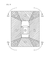
- FIG. 8 is a diagram of a mask image according to an embodiment of the present invention.
- FIG. 9 is a diagram illustrating a cause of the overlapping region when two cameras capture the same object.
- FIG. 10 is a diagram of weight information for pixels in the overlapping region of the mask image according to an embodiment of the present invention.
- FIG. 11 is a diagram of an image overlay-processed corresponding to FIG. 10 .
- FIG. 12 is a diagram of a surrounding image including the overlay-processed overlapping region according to an embodiment of the present invention.
- FIG. 13 is a diagram of a screen configuration of a display apparatus according to an embodiment of the present invention.
- FIG. 14 is a diagram of a screen displayed in the display apparatus of FIG. 13 .
- FIGS. 1 through 4 are diagrams of cameras installed to a vehicle according to an embodiment of the present invention.
- a surrounding image generating system is a system for securing visibility to allow a driver to check 360° around a vehicle by correcting images captured by four cameras 110 , 120 , 130 , and 140 of a three-dimensional space installed to the vehicle.
- the cameras 110 , 120 , 130 , and 140 are installed in front, rear, left, and right sides of the vehicle as shown in FIG. 1 , and the camera requires an optical angle over at least 180° to minimize blind spots of the vehicle.
- an installation height of the camera is set to maintain a region of the overlapping view angle of two cameras at least 1000 ⁇ 1000 mm 2 . As the installation height of the camera is high, better image quality can be attained. As such, it is important to set the locations of the cameras to address the blind spots of the vehicle and to set the installation location and the view angle to minimize the image quality degradation of the synthesized surrounding image.
- the locations of the four cameras installed to the vehicle are explained in more detail.
- the front camera 110 is installed to the center of a hood of the vehicle, and the left camera 130 and the right camera 140 are installed at the edge of or below both side-view mirrors of the vehicle.
- the rear camera 120 is installed to the center above a rear bumper as shown in FIG. 3 .
- the front camera 110 and the rear camera 120 are installed to capture more than 170° based on the vertical line of the ground direction.
- the left camera 130 and the right camera 140 are installed to capture more than 170° based on the vertical line of the ground direction.
- the installation location of each camera varies according to the type of the vehicle and may be limited by a design of the vehicle.
- a wide-angle camera is subject to the image quality degradation because of lack of the light around a lens, and more distortion occurs around the lens than the center of the lens.
- the quality of the image around the lens is severely degraded.
- the front camera 110 and the rear camera 120 are installed such that their optical axis is parallel with the horizon and the left camera 130 and the right camera 140 are installed perpendicularly to the ground.
- the heights of the cameras 110 , 120 , 130 , and 140 are set to capture the range away from the front, the rear, the left side, and the right side of the vehicle about 1.5 m. At this time, the camera can take a picture from about 30° to 60° from the vertical axis based on the ground.
- FIG. 5 is a diagram of a structure of a surrounding image generating system according to an embodiment of the present invention.
- the surrounding image generating system can include the plurality of the cameras 110 , 120 , 130 , and 140 , an image generating apparatus 200 , and a display apparatus 300 .
- the plurality of the cameras 110 , 120 , 130 , and 140 is installed to the front, the rear, the left side, and the right side of the vehicle respectively, and can include a lens of a wide view angle such as wide-angle lens or fisheye lens.
- the cameras 110 , 120 , 130 , and 140 include a pinhole camera.
- the cameras 110 , 120 , 130 , and 140 capture a three-dimensional object as two-dimensional images D 1 , D 2 , D 3 and D 4 through the lens of the wide view angle over 170°, and the captured images are sent to the image generating apparatus 200 via four channels ch 1 , ch 2 , ch 3 , and ch 4 respectively.
- the image generating apparatus 200 includes an image input part 210 , an image processing part 230 , an image synthesis part 250 , a control part 270 , and a communication part 290 .
- the image input part 210 receives the images D 1 , D 2 , D 3 and D 4 captured through the plurality of the cameras 110 , 120 , 130 , and 140 via the respective channels ch 1 , ch 2 , ch 3 , and ch 4 .
- the image processing part 230 processes the captured images D 1 , D 2 , D 3 and D 4 received from the image input part 210 using a look up table, and generates and outputs corrected images E 1 , E 2 , E 3 and E 4 from the captured images D 1 , D 2 , D 3 and D 4 .
- the look up table can be generated by applying a distortion correction algorithm, an Affine transformation algorithm, and a viewpoint transformation algorithm.
- the image synthesis part 250 receives the corrected images E 1 , E 2 , E 3 and E 4 corrected by the image processing part 230 , and processes to synthesize the received corrected images E 1 , E 2 , E 3 and E 4 in an overlay scheme which overlaps the images.
- the image synthesis part 250 processes the overlay synthesis using a mask image.
- the mask image contains region information per channel ch 1 , ch 2 , ch 3 , and ch 4 and weight information of pixels constituting the corrected image.
- the control part 270 controls to naturally display the overlapping region by adjusting the weight of the pixels in the overlapping region between the corrected images E 1 , E 2 , E 3 and E 4 .
- the image synthesis part 250 generates the surrounding image through which 360° around the vehicle can be perceived at a look by synthesizing and processing the four corrected images E 1 , E 2 , E 3 and E 4 in the overlay manner.
- the communication part 290 receives a current driving state signal from gears, a wheel, a speedometer, a driving device of the vehicle through CAN communication or LIN communication.
- the communication part 290 forwards the received signal to the control part 270 , and the control part 270 determines the surrounding image displayed in the display apparatus 300 according to the driving state. For example, to prevent traffic accidents, the control part 270 controls not to display the surrounding image when the vehicle is running at over a certain speed.
- the display apparatus 300 which is a device capable of displaying the surrounding image generated by the image synthesis part 250 , can be implemented using a display or a navigation installed in the vehicle, and may be included to the image generating apparatus 200 .
- FIG. 6 is a flowchart of the surrounding image generating method according to an embodiment of the present invention.
- the image generating apparatus 200 receives the images D 1 , D 2 , D 3 and D 4 captured through the cameras 110 , 120 , 130 , and 140 via the channels ch 1 , ch 2 , ch 3 , and ch 4 (S 310 ).
- the composition of the captured images D 1 , D 2 , D 3 and D 4 varies according to the installation location and height of the cameras 110 , 120 , 130 , and 140 .
- the image generating apparatus 200 corrects the received captured images D 1 , D 2 , D 3 and D 4 using the look up table (S 320 ) and thus generates the corrected images E 1 , E 2 , E 3 and E 4 fit for the overlay processing.
- the look up table adopts the distortion correction algorithm, the Affine transformation algorithm, and the viewpoint transformation algorithm, which are described now.
- the distortion correction algorithm is an algorithm for correcting geometric distortion caused by the camera lens.
- the geometric distortion of the lens for example, radial distortion or tangential distortion can take place. Due to such lens distortion, a straight line in the captured image can be transformed and represented as a curved line. That is, pincushion distortion where a distortion factor k indicating the distortion of the lens is smaller than zero can occur, or barrel distortion where the lens distortion factor k is greater than zero can occur.
- the distortion correction algorithm can be expressed using a function of a correction parameter and the distortion factor.
- the correction parameter can include the focal length and optical center coordinates of the lens mounted to the camera, and the distortion factor can include a radial distortion factor and a tangential distortion factor.
- the distortion correction algorithm of Equation 1 can be applied.
- u f x ⁇ x′ ⁇ (1 +k 1 ⁇ r 2 +k 2 ⁇ r 4 )+2 p 1 ⁇ x′ ⁇ y′+p 2 ( r 2 +2 x′ 2 ) ⁇ + c x
- v f y ⁇ y′ ⁇ (1 +k 1 ⁇ r 2 +k 2 ⁇ r 4 )+ p 1 ( r 2 +2 y′ 2 )+2 p 2 ⁇ x′ ⁇ y′ ⁇ +c y [Equation 1]
- x′ and y′ denote coordinates of a correction index image on an image plane
- u and v denote coordinates on a lens plane to which three-dimensional space coordinates are projected
- f x and f y denote the focal length of the lens
- c x and c y denote the optical center coordinates of the lens.
- k 1 and k 2 denote the radial distortion factor
- p 1 and p 2 denote the tangential distortion factor
- r 2 x′ 2 +y′ 2 .
- the correction index image can be formed in a lattice shape and is the image used to correct the geometric distortion of the lens.
- the Affine transformation indicates point mapping which represents the two-dimensional space in one dimension, and passes through rotation (R), translation (T), and scaling (S) transformations.
- R rotation
- T translation
- S scaling
- Equation 2 Equation 2
- W denotes two-dimensional color image data output through the Affine operation
- A denotes a first transformation coefficient for linear magnification and reduction
- D denotes two-dimensional color image data input on the frame basis
- B denotes a second transformation coefficient for linear translation of the two-dimensional color image data D.
- the viewpoint transformation algorithm transforms the captured images D 1 , D 2 , D 3 and D 4 input via the four channels into a top view viewpoint. That is, the viewpoint transformation algorithm transforms the viewpoint of the input images D 1 , D 2 , D 3 and D 4 to the image looked down from above.
- the correction process can be performed using one projective transformation algorithm by replacing the Affine transformation and the viewpoint transformation algorithm.
- FIG. 7 is a diagram of the projective transformation algorithm according to an embodiment of the present invention.
- the point (x, y) generated through the distortion correction algorithm as shown in FIG. 7 is transformed to (x′, y′) through the projective transformation algorithm H.
- the projective transformation algorithm H includes a 3 ⁇ 3 matrix as expressed in Equation 3.
- the projective transformation algorithm H of Equation 3 can be derived by applying the point (x, y) generated through the distortion correction algorithm and the point (x′, y′) to generate using the projective transformation into Equation 3. That is, the projective transformation algorithm H can be acquired by applying (0,0), (1,0), (2,1) and (0,1) to (x, y) and applying (0,0), (1,0), (1,1) and (0,1) to (x′, y′) as shown in FIG. 7 and processing the operation. By means of this projective transformation, it is possible to correct the distortion caused by the tilted camera and to transform the distorted image to the rectangular shape as shown in FIG. 7 .
- the look up table When the look up table is used as in embodiments of the present invention, it is possible to reduce the transformation processing time of the input images D 1 , D 2 , D 3 and D 4 .
- the transformation may be processed by applying the distortion correction, the Affine transformation, and the viewpoint transformation, or the distortion correction and the projective transformation to the input images D 1 , D 2 , D 3 and D 4 .
- the corrected images E 1 , E 2 , E 3 and E 4 output can be changed in various forms according to the setup of the look up table.
- the image generating apparatus 200 overlay-processes the corrected images E 1 , E 2 , E 3 and E 4 using the region information per channel ch 1 , ch 2 , ch 3 , and ch 4 and the weight information of the pixels stored in the mask image (S 330 ).
- the image generating apparatus 200 generates the final surrounding image of the vehicle by overlay-processing the overlapping region between the plurality of the corrected images using the mask image (S 340 ).
- FIG. 8 is a diagram of the mask image according to an embodiment of the present invention.
- the mask image is used to overlay and synthesize the four corrected images E 1 , E 2 , E 3 and E 4 to one image.
- the mask image contains the region information per channel ch 1 , ch 2 , ch 3 , and ch 4 and pixel value information corresponding to each region, and is divided into nine regions as shown in FIG. 8 .
- the mask image sets to overlay the image captured by the front camera 110 input via the channel ch 1 with the first, second, and third regions, and to overlay the image captured by the rear camera 120 input via the channel ch 2 with the seventh, eighth, and ninth regions.
- the mask image sets to overlay the image captured by the left camera 130 input via the channel ch 3 with the first, fourth, and seventh regions, and to overlay the image captured by the right camera 140 input via the channel ch 4 with the third, sixth, and ninth regions.
- the first, third, seventh, and ninth regions are the overlapping regions duplicately captured by the plurality of the cameras. That is, the first region is the overlapping region duplicately captured by the front camera 110 and the left camera 130 , and the third region is the overlapping region duplicately captured by the front camera 110 and the right camera 140 .
- the seventh region is the overlapping region duplicately captured by the rear camera 120 and the left camera 130
- the ninth region is the overlapping region duplicately captured by the rear camera 120 and the right camera 140 .
- the control part 270 moves the image corresponding to the second, fourth, sixth, and eighth regions which are not duplicately captured, to the same regions of the surrounding image corresponding to a destination image.
- the control part 270 overlay-processes the first, third, seventh, and ninth regions which are the overlapping regions duplicately captured by the multiple cameras, using the mask image.
- the mask image displays the second, fourth, sixth, and eighth regions in monochrome without color change.
- the fifth region corresponding to the vehicle is set to adjust R, G, and B pixel values.
- the mask image sets each pixel in the first, third, seventh, and ninth regions to have the R pixel value from 1 to 254.
- the mask image sets the R pixel value of each pixel in the first, third, seventh, and ninth regions to a Gradient weight value between 1 and 254 for the natural color matching as shown in FIG. 8 .
- the first region for example, sets the R pixel value of the pixel adjoining the second region to 1 and sets the R pixel value of the pixel adjoining the fourth region to 254 by increasing the R pixel value of the pixel closer to the fourth region.
- the third region sets the R pixel value of the pixel adjoining the second region to 1 and the R pixel value of the pixel adjoining the sixth region to 254.
- the seventh region sets the R pixel value of the pixel adjoining the eighth region to 1 and the R pixel value of the pixel adjoining the fourth region to 254.
- the ninth region sets the R pixel value of the pixel adjoining the eighth region to 1 and the R pixel value of the pixel adjoining the sixth region to 254.
- the control part 270 can perform the overlay operation by applying Equation 4 to each pixel in the first, third, seventh, and ninth regions.
- I ′( t+ 1) ⁇ I 1 ( t )+(1 ⁇ ) I 2 ( t ), 0 ⁇ 1 [Equation 4]
- I 1 (t) and I 2 (t) denote image information for the overlapping region input via two channels respectively
- ⁇ denotes the weight for the pixels in the overlapping region
- I′(t+1) denotes the overlay-processed image information.
- I 1 (t) denotes the image information for the overlapping region captured by the camera 110 installed to the front or the camera 120 installed to the rear and input via the channel ch 1 or the channel ch 2
- I 2 (t) denotes the image information for the overlapping region captured by the camera 130 installed to the left side or the camera 140 installed to the right side and input via the channel ch 3 or the channel ch 4 .
- ⁇ is the weight for the R pixel in the overlapping region.
- ⁇ is a value ( 1/255) close to zero.
- ⁇ is a value ( 254/255) close to 1.
- FIG. 9 is a diagram illustrating a cause of the overlapping region when two cameras capture the same object.
- FIG. 10 is a diagram of the weight information for the pixels in the overlapping region of the mask image according to an embodiment of the present invention
- FIG. 11 is a diagram of the image overlay-processed corresponding to FIG. 10 .
- the control part 270 can represent the overlay processing result as shown in (a) through (d) of FIG. 11 .
- FIG. 10 and FIG. 11 shows the completely independently separated images of the two cameras based on the image synthesis boundary. That is, when the weight information of FIG. 10A with respect to the overlapping region captured through the first camera and the second camera is applied to Equation 4, the overlay-processed image of (a) of FIG. 11 can be generated.
- (b) of FIG. 10 and FIG. 11 overlay-processes two images using an alpha blend method which linearly sets the weight between the adjacent pixels.
- the most natural image can be generated by linearly setting the weight between the adjacent pixels.
- (b) is most similar to the Gradient weight setting method explained in FIG. 8 and can produce the most natural image.
- FIG. 10 and FIG. 11 divides sections and overlay-processes such that an odd column outputs the image captured by the first camera and an even column outputs the image captured by the second camera.
- (d) of FIG. 10 and FIG. 11 overlay-processes such that the odd column outputs the image captured by the first camera and the even column outputs the image captured by the second camera, by adding the row segmentation to (c).
- the image generating apparatus 200 can generate the surrounding image naturally showing the overlapping region by overlay-processing the overlapping regions occurring between the corrected images E 1 , E 2 , E 3 and E 4 through the mask image.
- FIG. 12 is a diagram of the surrounding image including the overlay-processed overlapping region according to an embodiment of the present invention.
- the image generating apparatus 200 can receive the images D 1 , D 2 , D 3 and D 4 captured through the cameras 110 , 120 , 130 , and 140 via the four channels ch 1 , ch 2 , ch 3 , and ch 4 , overlay-process the overlapping regions using the mask image, and thus generate the surrounding image E synthesized to naturally display the overlapping regions.
- the image generating apparatus 200 since the brightness of the images D 1 , D 2 , D 3 and D 4 captured through the cameras 110 , 120 , 130 , and 140 can vary, the image generating apparatus 200 according to an embodiment of the present invention sets four indicators for the image D 1 captured by the camera 110 installed to the front of the vehicle and calculates an average value of the brightness for the four indicators. The image generating apparatus 200 applies the average brightness value to the four images D 1 , D 2 , D 3 and D 4 through a histogram equalizer so that the synthesized surround image E has the same brightness as much as possible.
- FIG. 13 is a diagram of a screen configuration of the display apparatus according to an embodiment of the present invention
- FIG. 14 is a diagram of a screen displayed in the display apparatus of FIG. 13 .
- the screen A outputs the front camera image D 1 when the vehicle is running, and displays the rear camera image D 2 when the vehicle is parking.
- the control part 270 detects a reverse gear on/off signal of the gearbox over the CAN communication of the vehicle and thus automatically switches the screen A.
- the driver can selectively change the front camera image D 1 and the rear camera image D 2 by directly touching a first button or a second button.
- the driver may change the image using a jog dial.
- the control part 270 receiving a steering angle signal of the vehicle via the communication part 290 can display a parking guide line and an expected trajectory in the screen A and thus provide convenience to the driver in the parking.
- the screen B displays the surrounding image E synthesized by the image generating apparatus 200 .
- the control part 270 can receive a signal from the communication part 290 and display the left camera image D 3 or the right camera image D 4 during the driving. Also, by considering safety of the driver, when the speed of the vehicle exceeds, for example, 20 km, the control part 270 may switch the screen A and the screen B to the off state.
- the driver can accurately recognize the situation around the vehicle. Therefore, the driver can park the vehicle in the convenient manner and drive the vehicle forward or backward in the safe manner even without looking at the side-view mirror or the rearview mirror.
Abstract
Description
I′(t+1)=αI 1(t)+(1−α)I 2(t), 0≦α≦1
where I1(t) and I2(t) denote image information for the overlapping region input via two channels respectively, a denotes α weight for pixels in the overlapping region, and I′(t+1) denotes the overlay-processed image information.
I′(t+1)=αI 1(t)+(1−α)I 2(t), 0≦α≦1
where I1(t) and I2(t) denote image information for the overlapping region input via two channels respectively, α denotes a weight for pixels in the overlapping region, and I′(t+1) denotes the overlay-processed image information.
u=f x ×{x′×(1+k 1 ×r 2 +k 2 ×r 4)+2p 1 ×x′×y′+p 2(r 2+2x′ 2)}+c x
v=f y ×{y′×(1+k 1 ×r 2 +k 2 ×r 4)+p 1(r 2+2y′ 2)+2p 2 ×x′×y′}+c y [Equation 1]
W=A×D+B [Equation 2]
I′(t+1)=αI 1(t)+(1−α)I 2(t), 0≦α≦1 [Equation 4]
Claims (8)
I′(t+1)=αI 1(t)+(1−α)I 2(t), 0≦α≦1
I′(t+1)=αI 1(t)+(1−α)I 2(t), 0≦α≦1
I′(t+1)=αI 1(t)+(1−α)I 2(t), 0≦α≦1
Applications Claiming Priority (3)
| Application Number | Priority Date | Filing Date | Title |
|---|---|---|---|
| KR10-2009-0000734 | 2009-01-06 | ||
| KR1020090000734A KR100966288B1 (en) | 2009-01-06 | 2009-01-06 | Around image generating method and apparatus |
| PCT/KR2009/007794 WO2010079912A1 (en) | 2009-01-06 | 2009-12-24 | Method and apparatus for generating a surrounding image |
Publications (2)
| Publication Number | Publication Date |
|---|---|
| US20110285848A1 US20110285848A1 (en) | 2011-11-24 |
| US8928753B2 true US8928753B2 (en) | 2015-01-06 |
Family
ID=42316635
Family Applications (1)
| Application Number | Title | Priority Date | Filing Date |
|---|---|---|---|
| US13/143,470 Active 2031-09-06 US8928753B2 (en) | 2009-01-06 | 2009-12-24 | Method and apparatus for generating a surrounding image |
Country Status (5)
| Country | Link |
|---|---|
| US (1) | US8928753B2 (en) |
| JP (1) | JP5684144B2 (en) |
| KR (1) | KR100966288B1 (en) |
| CN (1) | CN102271966B (en) |
| WO (1) | WO2010079912A1 (en) |
Cited By (24)
| Publication number | Priority date | Publication date | Assignee | Title |
|---|---|---|---|---|
| US20150062324A1 (en) * | 2012-04-13 | 2015-03-05 | Kyung Yong Choi | Iris recognition camera system for mobile device |
| US11034290B2 (en) * | 2017-10-10 | 2021-06-15 | Magna Mirrors Of America, Inc. | Vehicular vision system with ground illumination light module |
| US11082631B2 (en) | 2018-04-03 | 2021-08-03 | Aisin Seiki Kabushiki Kaisha | Image processing device |
| US11250240B1 (en) | 2020-07-27 | 2022-02-15 | Pony Ai Inc. | Instance segmentation using sensor data having different dimensionalities |
| US11403069B2 (en) | 2017-07-24 | 2022-08-02 | Tesla, Inc. | Accelerated mathematical engine |
| US11409692B2 (en) | 2017-07-24 | 2022-08-09 | Tesla, Inc. | Vector computational unit |
| US11487288B2 (en) | 2017-03-23 | 2022-11-01 | Tesla, Inc. | Data synthesis for autonomous control systems |
| US11523053B2 (en) | 2018-04-03 | 2022-12-06 | Aisin Corporation | Image processing apparatus |
| US11539871B2 (en) | 2020-05-28 | 2022-12-27 | Samsung Electronics Co., Ltd. | Electronic device for performing object detection and operation method thereof |
| US11537811B2 (en) | 2018-12-04 | 2022-12-27 | Tesla, Inc. | Enhanced object detection for autonomous vehicles based on field view |
| US11562231B2 (en) | 2018-09-03 | 2023-01-24 | Tesla, Inc. | Neural networks for embedded devices |
| US11561791B2 (en) | 2018-02-01 | 2023-01-24 | Tesla, Inc. | Vector computational unit receiving data elements in parallel from a last row of a computational array |
| US11567514B2 (en) | 2019-02-11 | 2023-01-31 | Tesla, Inc. | Autonomous and user controlled vehicle summon to a target |
| US11610117B2 (en) | 2018-12-27 | 2023-03-21 | Tesla, Inc. | System and method for adapting a neural network model on a hardware platform |
| US11636333B2 (en) | 2018-07-26 | 2023-04-25 | Tesla, Inc. | Optimizing neural network structures for embedded systems |
| US11665108B2 (en) | 2018-10-25 | 2023-05-30 | Tesla, Inc. | QoS manager for system on a chip communications |
| US11681649B2 (en) | 2017-07-24 | 2023-06-20 | Tesla, Inc. | Computational array microprocessor system using non-consecutive data formatting |
| US11734562B2 (en) | 2018-06-20 | 2023-08-22 | Tesla, Inc. | Data pipeline and deep learning system for autonomous driving |
| US11748620B2 (en) | 2019-02-01 | 2023-09-05 | Tesla, Inc. | Generating ground truth for machine learning from time series elements |
| US11790664B2 (en) | 2019-02-19 | 2023-10-17 | Tesla, Inc. | Estimating object properties using visual image data |
| US11816585B2 (en) | 2018-12-03 | 2023-11-14 | Tesla, Inc. | Machine learning models operating at different frequencies for autonomous vehicles |
| US11841434B2 (en) | 2018-07-20 | 2023-12-12 | Tesla, Inc. | Annotation cross-labeling for autonomous control systems |
| US11893393B2 (en) | 2017-07-24 | 2024-02-06 | Tesla, Inc. | Computational array microprocessor system with hardware arbiter managing memory requests |
| US11893774B2 (en) | 2018-10-11 | 2024-02-06 | Tesla, Inc. | Systems and methods for training machine models with augmented data |
Families Citing this family (71)
| Publication number | Priority date | Publication date | Assignee | Title |
|---|---|---|---|---|
| JP5064601B2 (en) * | 2009-06-29 | 2012-10-31 | パナソニック株式会社 | In-vehicle video display |
| JP5548002B2 (en) * | 2010-03-25 | 2014-07-16 | 富士通テン株式会社 | Image generation apparatus, image display system, and image generation method |
| JP5592138B2 (en) | 2010-03-31 | 2014-09-17 | 富士通テン株式会社 | Image generation apparatus, image display system, and image generation method |
| US9090263B2 (en) * | 2010-07-20 | 2015-07-28 | GM Global Technology Operations LLC | Lane fusion system using forward-view and rear-view cameras |
| JP5497617B2 (en) | 2010-11-16 | 2014-05-21 | 住友重機械工業株式会社 | Image generating apparatus and operation support system |
| EP2746139B1 (en) * | 2011-03-16 | 2017-02-22 | Toyota Jidosha Kabushiki Kaisha | Vehicle remote operation device |
| KR101241012B1 (en) * | 2011-06-27 | 2013-03-11 | 현대자동차일본기술연구소 | Method for improving images of around view monitor system |
| JP5853457B2 (en) * | 2011-07-20 | 2016-02-09 | アイシン精機株式会社 | Vehicle perimeter monitoring system |
| US8994825B2 (en) * | 2011-07-28 | 2015-03-31 | Robert Bosch Gmbh | Vehicle rear view camera system and method |
| KR101286267B1 (en) | 2011-10-05 | 2013-07-19 | 에스엘 주식회사 | Apparatus and method for displaying around vehicle |
| US9019347B2 (en) | 2011-10-13 | 2015-04-28 | Aisin Seiki Kabushiki Kaisha | Image generator |
| JP5870608B2 (en) * | 2011-10-13 | 2016-03-01 | アイシン精機株式会社 | Image generation device |
| US8902313B2 (en) * | 2011-11-02 | 2014-12-02 | Robert Bosch Gmbh | Automatic image equalization for surround-view video camera systems |
| KR101239740B1 (en) | 2011-12-08 | 2013-03-18 | 아진산업(주) | An apparatus for generating around view image of vehicle using polygon mapping and multi look-up table |
| KR101209072B1 (en) | 2011-12-08 | 2012-12-06 | 아진산업(주) | An apparatus for generating around view image of vehicle using warping equation and multi look-up table |
| CN103649426B (en) * | 2012-01-27 | 2016-05-11 | 斗山英维高株式会社 | The processing safety of building machinery improves device |
| PT106168A (en) * | 2012-02-20 | 2014-02-21 | Josias Rodrigues Rodrigues | AUTO INTERNAL SURVEILLANCE SYSTEM FOR THE ELIMINATION OF THE DEAD ANGLE |
| US20130286193A1 (en) * | 2012-03-21 | 2013-10-31 | Magna Electronics Inc. | Vehicle vision system with object detection via top view superposition |
| DE102013103952B4 (en) * | 2012-05-02 | 2020-07-09 | GM Global Technology Operations LLC | Lane detection at full speed with an all-round vision system |
| US9516277B2 (en) * | 2012-05-02 | 2016-12-06 | GM Global Technology Operations LLC | Full speed lane sensing with a surrounding view system |
| JP6031819B2 (en) * | 2012-05-17 | 2016-11-24 | 富士通株式会社 | Image processing apparatus and image processing method |
| KR101376211B1 (en) * | 2012-06-01 | 2014-03-21 | 현대모비스 주식회사 | Image composing apparatus of around view monitor system for changing view mode easily and method thereof |
| KR101376210B1 (en) * | 2012-08-06 | 2014-03-21 | 현대모비스 주식회사 | Around View Monitor System and Monitoring Method |
| JP6054738B2 (en) * | 2012-12-25 | 2016-12-27 | 京セラ株式会社 | Camera module, camera system, and image display method |
| JP6223685B2 (en) * | 2013-01-30 | 2017-11-01 | 富士通テン株式会社 | Image processing apparatus and image processing method |
| US9674490B2 (en) * | 2013-04-18 | 2017-06-06 | Magna Electronics Inc. | Vision system for vehicle with adjustable cameras |
| JP6036548B2 (en) * | 2013-05-22 | 2016-11-30 | 株式会社デンソー | Video control device for vehicle |
| KR101519209B1 (en) * | 2013-08-06 | 2015-05-11 | 현대자동차주식회사 | Apparatus and method for providing image |
| KR102128048B1 (en) * | 2013-10-11 | 2020-06-29 | 현대모비스 주식회사 | Welcome ystem with around view monitoring of vehicle and method thereof |
| JP6347934B2 (en) * | 2013-10-11 | 2018-06-27 | 株式会社デンソーテン | Image display device, image display system, image display method, and program |
| EP3065390B1 (en) * | 2013-10-29 | 2019-10-02 | Kyocera Corporation | Image correction parameter output device, camera system, and correction parameter output method |
| KR101572065B1 (en) * | 2014-01-03 | 2015-11-25 | 현대모비스(주) | Method for compensating image distortion and Apparatus for the same |
| JP6095592B2 (en) * | 2014-02-17 | 2017-03-15 | 日立建機株式会社 | Monitoring image display device for hydraulic excavator |
| JP6330383B2 (en) * | 2014-03-12 | 2018-05-30 | 株式会社デンソー | Composite image generation apparatus and composite image generation program |
| KR102211496B1 (en) | 2014-05-14 | 2021-02-03 | 주식회사 인텔리빅스 | Event detection system of blackbox for vehicle and method for event detection |
| KR101592740B1 (en) * | 2014-07-24 | 2016-02-15 | 현대자동차주식회사 | Apparatus and method for correcting image distortion of wide angle camera for vehicle |
| EP3029602A1 (en) * | 2014-12-04 | 2016-06-08 | Conti Temic microelectronic GmbH | Method and apparatus for detecting a free driving space |
| KR20160076737A (en) | 2014-12-23 | 2016-07-01 | 에스엘 주식회사 | Environment monitoring apparatus and method for vehicle |
| KR20160076736A (en) | 2014-12-23 | 2016-07-01 | 에스엘 주식회사 | Environment monitoring apparatus and method for vehicle |
| KR101678098B1 (en) | 2015-03-24 | 2016-11-23 | 에스엘 주식회사 | Environment monitoring apparatus for vehicle |
| EP3076363B1 (en) * | 2015-03-30 | 2019-09-25 | KNORR-BREMSE Systeme für Nutzfahrzeuge GmbH | Image synthesizer and a method for synthesizing an image |
| JP6224029B2 (en) * | 2015-05-21 | 2017-11-01 | 富士通テン株式会社 | Image processing apparatus and image processing method |
| CN104859542B (en) * | 2015-05-26 | 2017-06-27 | 寅家电子科技(上海)有限公司 | Vehicle-mounted monitoring system and vehicle-mounted monitoring processing method |
| KR101705558B1 (en) * | 2015-06-25 | 2017-02-13 | (주)캠시스 | Top view creating method for camera installed on vehicle and AVM system |
| EP3142066A1 (en) * | 2015-09-10 | 2017-03-15 | KNORR-BREMSE Systeme für Nutzfahrzeuge GmbH | Image synthesizer for a surround monitoring system |
| EP3144162B1 (en) | 2015-09-17 | 2018-07-25 | KNORR-BREMSE Systeme für Nutzfahrzeuge GmbH | Apparatus and method for controlling a pressure on at least one tyre of a vehicle |
| CN105894448B (en) * | 2015-11-06 | 2019-08-20 | 法法汽车(中国)有限公司 | The generation method of mask matrix, the synthetic method for image of parking and device |
| US9787951B2 (en) * | 2015-12-18 | 2017-10-10 | Serge Kannon | Vehicle proximity warning system |
| KR102571818B1 (en) | 2016-01-06 | 2023-08-29 | 삼성전자주식회사 | Head mounted type electronic device |
| JP6750519B2 (en) * | 2016-05-24 | 2020-09-02 | 株式会社Jvcケンウッド | Imaging device, imaging display method, and imaging display program |
| JP6868805B2 (en) * | 2016-06-07 | 2021-05-12 | パナソニックIpマネジメント株式会社 | Image generator, image generator, and program |
| KR101807090B1 (en) * | 2016-06-20 | 2017-12-08 | 현대오트론 주식회사 | Apparatus and method for revising image distortion |
| CN106204480B (en) * | 2016-07-08 | 2018-12-18 | 石家庄域联视控控制技术有限公司 | Pattern distortion antidote and real-time apparatus for correcting based on conic section |
| KR20180060753A (en) * | 2016-11-29 | 2018-06-07 | 주식회사 와이즈오토모티브 | Apparatus and method for supporting driving of vehicle |
| KR102551099B1 (en) | 2017-01-13 | 2023-07-05 | 엘지이노텍 주식회사 | Apparatus of providing an around view, method thereof and vehicle having the same |
| KR102429490B1 (en) * | 2017-09-05 | 2022-08-05 | 현대자동차주식회사 | Svm system for providing bvm image and operation method of the same |
| JP6920976B2 (en) * | 2017-12-15 | 2021-08-18 | 株式会社東海理化電機製作所 | Vehicle peripheral monitoring device |
| TWI688502B (en) * | 2018-02-14 | 2020-03-21 | 先進光電科技股份有限公司 | Apparatus for warning of vehicle obstructions |
| CN111886858B (en) * | 2018-03-15 | 2022-06-21 | 株式会社小糸制作所 | Image system for vehicle |
| KR102053099B1 (en) * | 2018-06-07 | 2019-12-06 | 현대오트론 주식회사 | Around view monitoring system and operating method thereof |
| JP7052632B2 (en) * | 2018-08-10 | 2022-04-12 | トヨタ自動車株式会社 | Peripheral display device for vehicles |
| CN109102464A (en) * | 2018-08-14 | 2018-12-28 | 四川易为智行科技有限公司 | Panorama Mosaic method and device |
| US10821972B2 (en) * | 2018-09-13 | 2020-11-03 | Ford Global Technologies, Llc | Vehicle remote parking assist systems and methods |
| JP7095537B2 (en) * | 2018-10-02 | 2022-07-05 | トヨタ自動車株式会社 | Image processing equipment, programs, information processing systems, and control methods |
| CN109754390B (en) * | 2018-12-11 | 2023-04-07 | 西北大学 | No-reference image quality evaluation method based on mixed visual features |
| KR102522923B1 (en) * | 2018-12-24 | 2023-04-20 | 한국전자통신연구원 | Apparatus and method for estimating self-location of a vehicle |
| DE112019006793T5 (en) * | 2019-01-31 | 2021-11-04 | Mitsubishi Electric Corporation | Driving assistance device |
| JP7251310B2 (en) * | 2019-05-22 | 2023-04-04 | 株式会社Jvcケンウッド | CAMERA POSITION DETECTION DEVICE, CAMERA UNIT, CAMERA POSITION DETECTION METHOD, AND PROGRAM |
| JP7251401B2 (en) | 2019-08-09 | 2023-04-04 | 株式会社デンソー | Peripheral image generation device, peripheral image generation method, and program |
| WO2021054797A1 (en) * | 2019-09-19 | 2021-03-25 | 주식회사 윌러스표준기술연구소 | Video signal processing method and apparatus using scaling process |
| DE102020101637A1 (en) * | 2020-01-24 | 2021-07-29 | Bayerische Motoren Werke Aktiengesellschaft | Generating a top view of a motor vehicle |
Citations (11)
| Publication number | Priority date | Publication date | Assignee | Title |
|---|---|---|---|---|
| US20010048446A1 (en) * | 2000-05-24 | 2001-12-06 | Akira Ishida | Rendering device |
| US20020005896A1 (en) * | 2000-05-23 | 2002-01-17 | Kiyoshi Kumata | Surround surveillance system for mobile body, and mobile body, car, and train using the same |
| JP2002087160A (en) | 2000-09-18 | 2002-03-26 | Denso Corp | Vehicular surrounding image processing device and recording medium |
| JP2002324235A (en) | 2001-04-24 | 2002-11-08 | Matsushita Electric Ind Co Ltd | Method for compositing and displaying image of on-vehicle camera and device for the same |
| JP2003050107A (en) | 2001-08-07 | 2003-02-21 | Matsushita Electric Ind Co Ltd | Camera calibration device |
| US20040017378A1 (en) * | 2002-07-25 | 2004-01-29 | Chi-Yang Lin | Overlay processing device and method |
| KR20040104578A (en) | 2002-04-22 | 2004-12-10 | 마쯔시다덴기산교 가부시키가이샤 | Camera corrector |
| US20060274147A1 (en) * | 2005-06-07 | 2006-12-07 | Nissan Motor Co., Ltd. | Image display device and method |
| US20070085901A1 (en) * | 2005-10-17 | 2007-04-19 | Sanyo Electric Co., Ltd. | Vehicle drive assistant system |
| JP2007274377A (en) | 2006-03-31 | 2007-10-18 | Denso Corp | Periphery monitoring apparatus, and program |
| CN101236654A (en) | 2007-01-31 | 2008-08-06 | 三洋电机株式会社 | Method and apparatus for camera calibration, and vehicle |
Family Cites Families (4)
| Publication number | Priority date | Publication date | Assignee | Title |
|---|---|---|---|---|
| CN100438623C (en) * | 1999-04-16 | 2008-11-26 | 松下电器产业株式会社 | Image processing device and monitoring system |
| JP2001283390A (en) * | 2000-03-30 | 2001-10-12 | Honda Motor Co Ltd | Periphery recognition device of vehicle |
| JP2002354468A (en) * | 2001-05-30 | 2002-12-06 | Clarion Co Ltd | Picture compositing method and picture compositing device and vehicle surrounding situation monitor device |
| JP2006050451A (en) * | 2004-08-06 | 2006-02-16 | Sumitomo Electric Ind Ltd | Obstacle warning system and image processing apparatus |
-
2009
- 2009-01-06 KR KR1020090000734A patent/KR100966288B1/en active IP Right Grant
- 2009-12-24 CN CN200980153868.2A patent/CN102271966B/en active Active
- 2009-12-24 JP JP2011545287A patent/JP5684144B2/en active Active
- 2009-12-24 WO PCT/KR2009/007794 patent/WO2010079912A1/en active Application Filing
- 2009-12-24 US US13/143,470 patent/US8928753B2/en active Active
Patent Citations (17)
| Publication number | Priority date | Publication date | Assignee | Title |
|---|---|---|---|---|
| US20020005896A1 (en) * | 2000-05-23 | 2002-01-17 | Kiyoshi Kumata | Surround surveillance system for mobile body, and mobile body, car, and train using the same |
| US20010048446A1 (en) * | 2000-05-24 | 2001-12-06 | Akira Ishida | Rendering device |
| JP2002087160A (en) | 2000-09-18 | 2002-03-26 | Denso Corp | Vehicular surrounding image processing device and recording medium |
| JP2002324235A (en) | 2001-04-24 | 2002-11-08 | Matsushita Electric Ind Co Ltd | Method for compositing and displaying image of on-vehicle camera and device for the same |
| US20020196340A1 (en) | 2001-04-24 | 2002-12-26 | Matsushita Electric Industrial Co., Ltd. | Image synthesis display method and apparatus for vehicle camera |
| JP2003050107A (en) | 2001-08-07 | 2003-02-21 | Matsushita Electric Ind Co Ltd | Camera calibration device |
| US20050179801A1 (en) | 2002-04-22 | 2005-08-18 | Michio Miwa | Camera corrector |
| KR20040104578A (en) | 2002-04-22 | 2004-12-10 | 마쯔시다덴기산교 가부시키가이샤 | Camera corrector |
| CN1659418A (en) | 2002-04-22 | 2005-08-24 | 松下电器产业株式会社 | Camera corrector |
| US7352388B2 (en) | 2002-04-22 | 2008-04-01 | Matsushita Electric Industrial Co., Ltd. | Camera calibrating apparatus |
| US20040017378A1 (en) * | 2002-07-25 | 2004-01-29 | Chi-Yang Lin | Overlay processing device and method |
| US20060274147A1 (en) * | 2005-06-07 | 2006-12-07 | Nissan Motor Co., Ltd. | Image display device and method |
| US20070085901A1 (en) * | 2005-10-17 | 2007-04-19 | Sanyo Electric Co., Ltd. | Vehicle drive assistant system |
| JP2007274377A (en) | 2006-03-31 | 2007-10-18 | Denso Corp | Periphery monitoring apparatus, and program |
| CN101236654A (en) | 2007-01-31 | 2008-08-06 | 三洋电机株式会社 | Method and apparatus for camera calibration, and vehicle |
| JP2008187566A (en) | 2007-01-31 | 2008-08-14 | Sanyo Electric Co Ltd | Camera calibration apparatus and method and vehicle |
| US20080231710A1 (en) | 2007-01-31 | 2008-09-25 | Sanyo Electric Co., Ltd. | Method and apparatus for camera calibration, and vehicle |
Cited By (28)
| Publication number | Priority date | Publication date | Assignee | Title |
|---|---|---|---|---|
| US9824272B2 (en) * | 2012-04-13 | 2017-11-21 | Kyung Yong Choi | Iris recognition camera system for mobile device |
| US20150062324A1 (en) * | 2012-04-13 | 2015-03-05 | Kyung Yong Choi | Iris recognition camera system for mobile device |
| US11487288B2 (en) | 2017-03-23 | 2022-11-01 | Tesla, Inc. | Data synthesis for autonomous control systems |
| US11681649B2 (en) | 2017-07-24 | 2023-06-20 | Tesla, Inc. | Computational array microprocessor system using non-consecutive data formatting |
| US11403069B2 (en) | 2017-07-24 | 2022-08-02 | Tesla, Inc. | Accelerated mathematical engine |
| US11409692B2 (en) | 2017-07-24 | 2022-08-09 | Tesla, Inc. | Vector computational unit |
| US11893393B2 (en) | 2017-07-24 | 2024-02-06 | Tesla, Inc. | Computational array microprocessor system with hardware arbiter managing memory requests |
| US11034290B2 (en) * | 2017-10-10 | 2021-06-15 | Magna Mirrors Of America, Inc. | Vehicular vision system with ground illumination light module |
| US11679711B2 (en) | 2017-10-10 | 2023-06-20 | Magna Mirrors Of America, Inc. | Vehicular exterior lighting system with ground illumination |
| US11797304B2 (en) | 2018-02-01 | 2023-10-24 | Tesla, Inc. | Instruction set architecture for a vector computational unit |
| US11561791B2 (en) | 2018-02-01 | 2023-01-24 | Tesla, Inc. | Vector computational unit receiving data elements in parallel from a last row of a computational array |
| US11082631B2 (en) | 2018-04-03 | 2021-08-03 | Aisin Seiki Kabushiki Kaisha | Image processing device |
| US11523053B2 (en) | 2018-04-03 | 2022-12-06 | Aisin Corporation | Image processing apparatus |
| US11734562B2 (en) | 2018-06-20 | 2023-08-22 | Tesla, Inc. | Data pipeline and deep learning system for autonomous driving |
| US11841434B2 (en) | 2018-07-20 | 2023-12-12 | Tesla, Inc. | Annotation cross-labeling for autonomous control systems |
| US11636333B2 (en) | 2018-07-26 | 2023-04-25 | Tesla, Inc. | Optimizing neural network structures for embedded systems |
| US11562231B2 (en) | 2018-09-03 | 2023-01-24 | Tesla, Inc. | Neural networks for embedded devices |
| US11893774B2 (en) | 2018-10-11 | 2024-02-06 | Tesla, Inc. | Systems and methods for training machine models with augmented data |
| US11665108B2 (en) | 2018-10-25 | 2023-05-30 | Tesla, Inc. | QoS manager for system on a chip communications |
| US11816585B2 (en) | 2018-12-03 | 2023-11-14 | Tesla, Inc. | Machine learning models operating at different frequencies for autonomous vehicles |
| US11537811B2 (en) | 2018-12-04 | 2022-12-27 | Tesla, Inc. | Enhanced object detection for autonomous vehicles based on field view |
| US11908171B2 (en) | 2018-12-04 | 2024-02-20 | Tesla, Inc. | Enhanced object detection for autonomous vehicles based on field view |
| US11610117B2 (en) | 2018-12-27 | 2023-03-21 | Tesla, Inc. | System and method for adapting a neural network model on a hardware platform |
| US11748620B2 (en) | 2019-02-01 | 2023-09-05 | Tesla, Inc. | Generating ground truth for machine learning from time series elements |
| US11567514B2 (en) | 2019-02-11 | 2023-01-31 | Tesla, Inc. | Autonomous and user controlled vehicle summon to a target |
| US11790664B2 (en) | 2019-02-19 | 2023-10-17 | Tesla, Inc. | Estimating object properties using visual image data |
| US11539871B2 (en) | 2020-05-28 | 2022-12-27 | Samsung Electronics Co., Ltd. | Electronic device for performing object detection and operation method thereof |
| US11250240B1 (en) | 2020-07-27 | 2022-02-15 | Pony Ai Inc. | Instance segmentation using sensor data having different dimensionalities |
Also Published As
| Publication number | Publication date |
|---|---|
| JP2012514558A (en) | 2012-06-28 |
| CN102271966A (en) | 2011-12-07 |
| WO2010079912A1 (en) | 2010-07-15 |
| US20110285848A1 (en) | 2011-11-24 |
| KR100966288B1 (en) | 2010-06-28 |
| JP5684144B2 (en) | 2015-03-11 |
| CN102271966B (en) | 2014-04-30 |
Similar Documents
| Publication | Publication Date | Title |
|---|---|---|
| US8928753B2 (en) | Method and apparatus for generating a surrounding image | |
| US9056630B2 (en) | Lane departure sensing method and apparatus using images that surround a vehicle | |
| US8514282B2 (en) | Vehicle periphery display device and method for vehicle periphery image | |
| KR101510655B1 (en) | Around image generating method and apparatus | |
| US8384782B2 (en) | Apparatus and method for displaying bird's eye view image of around vehicle to facilitate perception of three dimensional obstacles present on a seam of an image | |
| JP4596978B2 (en) | Driving support system | |
| US9238434B2 (en) | Rear view mirror simulation | |
| JP4976685B2 (en) | Image processing device | |
| US8477191B2 (en) | On-vehicle image pickup apparatus | |
| CN107027329B (en) | Stitching together partial images of the surroundings of a running tool into one image | |
| WO2002089484A1 (en) | Method and apparatus for synthesizing/displaying images of cameras installed in vehicle | |
| JP5051263B2 (en) | Vehicle rear view system | |
| US20140043466A1 (en) | Environment image display apparatus for transport machine | |
| US11273763B2 (en) | Image processing apparatus, image processing method, and image processing program | |
| KR101657673B1 (en) | Apparatus and method for generating panorama view | |
| KR20100005971A (en) | A vehicle around view monitorring system | |
| GB2484583A (en) | Removal of distortions from image captured by a wide angle lens | |
| US10821900B2 (en) | Image processing device | |
| JP4706896B2 (en) | Wide-angle image correction method and vehicle periphery monitoring system | |
| CN104859542B (en) | Vehicle-mounted monitoring system and vehicle-mounted monitoring processing method | |
| JP2018152014A (en) | Video display device for vehicle | |
| CN117011185B (en) | Electronic rearview mirror CMS image correction method and system and electronic rearview mirror | |
| JP6805900B2 (en) | Image processing equipment, camera equipment, and driving support equipment | |
| CN117011185A (en) | Electronic rearview mirror CMS image correction method and system and electronic rearview mirror |
Legal Events
| Date | Code | Title | Description |
|---|---|---|---|
| AS | Assignment |
Owner name: IMAGENEXT CO., LTD., KOREA, REPUBLIC OF Free format text: ASSIGNMENT OF ASSIGNORS INTEREST;ASSIGNORS:HAN, YOUNG IN;SONG, YOUNG GI;BACK, WON IN;REEL/FRAME:026549/0791 Effective date: 20110704 |
|
| STCF | Information on status: patent grant |
Free format text: PATENTED CASE |
|
| AS | Assignment |
Owner name: KSS-IMAGENEXT CO., LTD., KOREA, REPUBLIC OF Free format text: CHANGE OF NAME;ASSIGNOR:IMAGENEXT CO., LTD.;REEL/FRAME:038903/0360 Effective date: 20160607 |
|
| FEPP | Fee payment procedure |
Free format text: ENTITY STATUS SET TO UNDISCOUNTED (ORIGINAL EVENT CODE: BIG.) |
|
| MAFP | Maintenance fee payment |
Free format text: PAYMENT OF MAINTENANCE FEE, 4TH YEAR, LARGE ENTITY (ORIGINAL EVENT CODE: M1551) Year of fee payment: 4 |
|
| AS | Assignment |
Owner name: BEYOND I CO., LTD., KOREA, REPUBLIC OF Free format text: CHANGE OF NAME;ASSIGNOR:KSS-IMAGENEXT CO., LTD.;REEL/FRAME:055744/0964 Effective date: 20200902 |
|
| MAFP | Maintenance fee payment |
Free format text: PAYMENT OF MAINTENANCE FEE, 8TH YEAR, LARGE ENTITY (ORIGINAL EVENT CODE: M1552); ENTITY STATUS OF PATENT OWNER: LARGE ENTITY Year of fee payment: 8 |