RELATED APPLICATIONS AND PRIORITY
This patent application claims the benefit of provisional patent application No. 60/934,236 entitled “Axially Centered Syringe Infusion Pump Drive Mechanism,” filed Jun. 11, 2007, incorporated herein by reference.
FIELD
This patent application generally relates to infusion pumps. More particularly it relates to syringe infusion pumps. More particularly it relates to a drive mechanism for syringe infusion pumps.
BACKGROUND
Infusion pumps currently present in the market consist of two basic types, syringe infusion pumps and volumetric infusion pumps. Typically, syringe infusion pumps accept a range of syringe sizes, typically from 1 cc to 60 cc or more in volume from a variety of syringe manufacturers. Typically these devices use a motor under control of a microprocessor. A motor such as is available from Maxon Precision Motors, Inc., Fall River, Mass., can be used. The motor is connected to a lead screw which advances a pushing element that pushes against the plunger of the syringe, driving it into the barrel of the syringe, thus dispensing fluid or other material. The devices have used sensors for determining the size of syringe loaded, the position of the plunger within its travel, whether the plunger is captured by the pushing element, and the driving force needed to push the plunger. The devices have also included encoders or other means for determining the motor speed.
The syringe drives have fixed the barrel of the syringe against a fixture, such as a V-block. A spring loaded clamp mechanism has been used to capture the barrel of the syringe against the V-block. Because the barrel diameter of a 1 cc syringe is significantly smaller than the barrel diameter of a 60 cc syringe, the pushing element has not always pushed along the center line of the syringe, and the variance between pushing element and syringe center line can be as much as 1 inch or more. The variance in the syringe center line with respect to the pushing surface has caused difficulties in measuring the force applied to the syringe which is used to estimate fluid pressure within the syringe. The variance has also caused inaccuracy in the resultant flow rate because the syringe plunger has not been driven into the syringe barrel squarely. Thus better schemes for mounting a syringe and driving its plunger are needed to eliminate these problems, and these schemes are provided by this patent application.
SUMMARY
One aspect of the present patent application is a syringe infusion pump that includes a syringe, a syringe barrel holder, and a force sensor. The syringe includes a barrel and a plunger. The plunger has a plunger axis. The barrel has a barrel axis and a barrel diameter. The syringe is one of a plurality of syringes, each having a different barrel diameter. The syringe barrel holder provides the barrel axis automatically aligned with the force sensor for each syringe of the plurality of syringes.
Another aspect is a syringe infusion pump that includes a syringe, a syringe plunger holder, and a force sensor. The syringe includes a barrel and a plunger. The plunger has a plunger axis and the barrel has a barrel diameter. The syringe is one of a plurality of syringes, each having a different barrel diameter. The syringe holder includes a plunger holder. The syringe plunger holder maintains a constant plunger axis independent of the barrel diameter.
Another aspect is a syringe infusion pump that includes a syringe, a syringe plunger holder, and a force sensor. The syringe includes a barrel and a plunger. The plunger has a plunger axis. The barrel has a barrel axis and a barrel diameter. The syringe is one of a plurality of syringes, each having a different barrel diameter. The syringe plunger holder provides the plunger axis approximately aligned with the barrel axis independent of the barrel diameter.
Another aspect is a syringe infusion pump that includes a syringe, a syringe barrel holder, and a force sensor. The syringe includes a barrel and a plunger. The barrel has a barrel axis and a barrel diameter. The syringe is one of a plurality of syringes, each having a different barrel diameter. The plurality of syringes includes a syringe having a smallest barrel diameter. The syringe barrel holder provides the barrel axis approximately aligned with the force sensor for a syringe having a barrel diameter that is less than or equal to two times the smallest barrel diameter.
A syringe infusion pump, comprising a syringe, a motor, a drive head, and a drive head position sensing mechanism. The motor is connected to move the drive head to facilitate operating the syringe. The drive head position sensing mechanism includes a guide rod, a pin, and a guide rod sensor. The guide rod has a helical groove. The pin extends from the drive head and fits in the helical groove. The guide rod rotates as the drive head moves, and the guide rod sensor senses rotation of the guide rod for use in determining drive head position.
Another aspect is a method of providing a fluid. The method includes providing a syringe, wherein the syringe includes a barrel and a plunger. The plunger has a plunger axis. The barrel has a barrel axis and a barrel diameter. The syringe is one of a plurality of syringes, each having a different barrel diameter. The method also includes providing a syringe infusion pump that includes a syringe barrel holder and a force sensor. The barrel syringe holder provides the barrel axis automatically aligned with the force sensor for each syringe of the plurality of syringes. The method also includes using the syringe infusion pump to provide the fluid.
BRIEF DESCRIPTION OF THE DRAWINGS
The foregoing will be apparent from the following detailed description as illustrated in the accompanying drawings, for clarity not drawn to scale, in which:
FIG. 1 is a three dimensional view of one embodiment of a syringe infusion pump of the present patent application;
FIG. 2 is a three dimensional view of a drive head, motor, and position sensing mechanism of the syringe infusion pump of FIG. 1;
FIGS. 3 a-3 c are a three dimensional cutaway views of a portion of the drive head of FIG. 2 showing a plunger in position in front of a force sensor, and showing plunger clamp elements maintaining the plunger axis in front of the center of the force sensor;
FIG. 4 is another three dimensional view of the drive head of FIG. 2;
FIG. 5 is a block diagram of electronic components for the syringe infusion pump;
FIGS. 6 a-6 d are three dimensional views of the barrel holder portion of the syringe holder of FIG. 1 showing how the axis of the barrel is maintained in the same position regardless of the diameter of the barrel; and
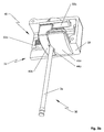
FIG. 7 is another three dimensional view of the barrel holder portion of the syringe holder of FIGS. 6 a-6 d.
DETAILED DESCRIPTION
One embodiment of the present patent application provides a syringe infusion pump with a force sensor and a syringe holder. In this embodiment the syringe holder includes a syringe plunger holder and a syringe barrel holder. The syringe holder can include mechanisms that provide the syringe plunger axis and the syringe barrel axis automatically aligned with the force sensor for all sized syringes.
Syringe infusion pump 20 includes drive head 22, syringe barrel holder 24, motor 26, lead screw 28, and position sensing device 30, as shown in FIGS. 1 and 2.
Motor 26 turns lead screw 28 clockwise or counterclockwise to move drive head 22 toward or away from syringe barrel holder 24. Drive head 22 includes force sensor 32 against which plunger 36 of syringe 38 is positioned, as shown in FIGS. 3 a-3 c. Force sensor 32 can be one available from Strain Measurement Devices, Meriden, Conn. Plunger 36 is held in position against force sensor 32 by syringe plunger holder and syringe plunger flange holder 40 that includes front plunger clamp element 42 a and rear plunger clamp element 42 b. Plunger clamp elements 42 a, 42 b have V- grooves 44 a, 44 b that both hold plunger 36 and capture plunger flange 46. Thus, plunger axis 54 extends directly into center 56 of force sensor 32, as shown in FIGS. 3 a-3 c and FIG. 4.
Plunger clamp elements 42 a, 42 b are connected to gear 48 through racks 50 a, 50 b so that plunger clamp elements 42 a, 42 b are constrained to move equal distances in opposite directions to each other, maintaining plunger flange 46 centered before force sensor 32 and maintaining plunger axis 54 of plunger 36 extending directly into center 56 of force sensor 32, regardless of the diameter of plunger 36. Gear 48, racks 50 a, 50 b are included in drive head housing 58. One embodiment has a first plunger flange holder drive shaft that includes rack 50 a and a second plunger flange holder drive shaft that includes rack 50 b.
Post 60 holds spring 62 for providing pressure for restoring plunger clamp elements 42 a, 42 b toward each other, as shown in FIG. 4.
Force sensor 32 senses the force being applied to plunger 36 by drive head 22. Force sensor 32 is connected to motor processor 64 on electronic circuit board 66. Motor 26, barrel sensor 76, and position sensor 78 are also connected to motor processor 64 on electronic circuit board 66. Motor processor 64 can be one available from Microchip Technology Inc., Chandler, Ariz. Barrel sensor 76 and position sensor 78 can be ones available from US Digital, Inc., Vancouver, Wash. Electronic circuit board 66 also includes main microprocessor 68. Keypad 70, display 72, and battery 74 are connected to main microprocessor 68. Main processor 68 and display 72 can be ones available from Sharp Electronics Corporation, Romeoville, Ill.
Motor processor 64 controls speed of motor 26 in a software closed control loop by monitoring two quadrature signals emitted by a motor encoder that is part of motor 26. Motor processor 64 monitors output of force sensor 32 and provides an alarm signal to alarm 79 if a preset force above a threshold is detected. This force translates to a resultant fluid pressure based upon the cross sectional area of syringe barrel 96. Motor processor 64 also monitors barrel sensor 76 and determines its outer diameter and thence its volume based upon a software look up table that cross references barrel diameter to syringe barrel volume. Motor processor 64 also monitors position sensor 78 and from this position determines the state of fill of syringe barrel 96 installed.
Main processor 68 sends the display information to display 72 to be visually communicated to the user. Main processor 68 also monitors keypad 70 to enable the user to control the device via key press.
Battery 74 supplies power to all the electronics and motor 26.
Position of drive head 22 along lead screw 28 is measured with position sensing device 30, as shown in FIGS. 1 and 2. Position sensing device 30 includes guide rod 80 and position sensor 78. Guide rod 80 has helical groove 84. Pin 86 extends from drive head 22 into helical groove 84 and causes guide rod 80 to rotate as drive head 22 moves under control of lead screw 28 and motor 26. Because helical groove 84 extends only once around guide rod 80, rotation of guide rod 80 can be used to accurately determine position of drive head 22 along lead screw 28. Rotation of guide rod 80 is measured with position sensor 78, and data from position sensor 78 is fed to motor processor 64 on circuit board 66. In one embodiment, position sensor 78 includes an absolute encoder for detecting angular movement of guide rod 80.
Syringe barrel holder 24 includes front barrel clamp element 90 a and rear barrel clamp element 90 b, as shown in FIGS. 6 a-6 d. Front barrel clamp element 90 a has a curved portion 94 to hold syringe barrel 96 in position within groove 98 in rear barrel clamp element 90 b. Groove 98 of rear barrel clamp element 90 b may have different flat regions 100 a, 100 b to facilitate accommodating barrels having different diameters. Flat regions 100 c can be used to facilitate accommodating barrels having collars.
Syringe barrel holder 24 also includes barrel flange clamp 102 on the side facing drive head 22, as shown in FIGS. 6 a-6 d and 7. Barrel flange clamp 102 is for capturing barrel flange 104 in a fixed position, as shown in FIGS. 6 a-6 d and FIG. 7 so that position of drive head 22 alone determines the amount of penetration of plunger into syringe barrel 96. Syringe holder 106 includes syringe plunger holder and syringe plunger flange holder 40 and syringe barrel holder 24.
Syringe barrel holder 24 also includes barrel centering mechanism 108 for automatically centering barrel axis 110 of barrel 96 along plunger axis 54 and along center 56 of force sensor 32. Barrel centering mechanism 108 provides that both front barrel clamp element 90 a and rear barrel clamp element 90 b move equal distances in opposite directions when syringe barrel 96 is inserted, maintaining barrel axis 110 in fixed position regardless of the size of barrel 96, as shown in FIGS. 6 a-6 d.
Barrel centering mechanism 108 includes barrel racks 112 a, 112 b, as shown in FIGS. 6 a-6 d. Barrel rack 112 a is connected to front barrel clamp element 90 a and to barrel clamp sensor gear 114 located in base 116, as shown in FIG. 1. Barrel rack 112 b is connected to rear barrel clamp element 90 b and to barrel clamp sensor gear 114. Barrel sensor 76 is also connected to barrel clamp sensor gear 114, and from the magnitude of rotation it measures of barrel clamp sensor gear 114 barrel sensor 76 determines the size of syringe barrel 96. In one embodiment, barrel sensor 76 includes an absolute encoder for detecting angular movement of barrel clamp sensor gear 114. In another embodiment, barrel sensor 76 includes an absolute encoder whose angular movement provides a measure of the movement of barrel rack 112 a, as shown in FIGS. 6 b-6 d. One embodiment has a first barrel holder drive shaft that includes barrel rack 112 a and a second barrel holder drive shaft that includes barrel rack 112 b.
Spring shaft 124 carries spring 126 that provides a force against base 116 pulling front barrel clamp element 90 a toward rear barrel clamp element 90 b to apply pressure to and hold syringe barrel 96. Guide shaft 128 extends from front barrel clamp element 90 a through rear barrel clamp element 90 b and into base 116.
While the disclosed methods and systems have been shown and described in connection with illustrated embodiments, various changes may be made therein without departing from the spirit and scope of the invention as defined in the appended claims.