US8897765B2 - Method and appratus for controlling signal transmission - Google Patents
Method and appratus for controlling signal transmission Download PDFInfo
- Publication number
- US8897765B2 US8897765B2 US12/417,675 US41767509A US8897765B2 US 8897765 B2 US8897765 B2 US 8897765B2 US 41767509 A US41767509 A US 41767509A US 8897765 B2 US8897765 B2 US 8897765B2
- Authority
- US
- United States
- Prior art keywords
- base station
- signal receiving
- signal
- receiving node
- data rate
- Prior art date
- Legal status (The legal status is an assumption and is not a legal conclusion. Google has not performed a legal analysis and makes no representation as to the accuracy of the status listed.)
- Active, expires
Links
Images


Classifications
-
- H—ELECTRICITY
- H04—ELECTRIC COMMUNICATION TECHNIQUE
- H04W—WIRELESS COMMUNICATION NETWORKS
- H04W92/00—Interfaces specially adapted for wireless communication networks
- H04W92/04—Interfaces between hierarchically different network devices
- H04W92/10—Interfaces between hierarchically different network devices between terminal device and access point, i.e. wireless air interface
-
- H—ELECTRICITY
- H04—ELECTRIC COMMUNICATION TECHNIQUE
- H04B—TRANSMISSION
- H04B7/00—Radio transmission systems, i.e. using radiation field
- H04B7/02—Diversity systems; Multi-antenna system, i.e. transmission or reception using multiple antennas
- H04B7/022—Site diversity; Macro-diversity
Definitions
- the following description relates to a method and apparatus for controlling a signal transmission which controls whether to cooperatively transmit a signal using a data rate and a signal to noise ratio (SNR) between a base station and a signal receiving node.
- SNR signal to noise ratio
- a user located in a cell edge experiences a case where a data rate is degraded due to co-channel interference (CCI) from adjacent base stations using identical frequency resources.
- CCI co-channel interference
- MIMO network multiple-input multiple-output
- performance may vary depending on accuracy of feedback information since channel information between transmission/reception is required to be known to a base station.
- IUI inter-user interference
- CCI C-user interference
- the CCI may be removed, yet the IUI may be increased due to an error occurring between a quantized channel vector and an actual vector.
- a method for controlling signal transmission includes determining whether a signal to noise ratio (SNR) between a first base station and a signal receiving node is less than a threshold, and controlling the first base station and a second base station to cooperatively transmit a signal to the signal receiving node in response to the SNR being less than the threshold, where the second base station is included in an adjacent cell to a cell including the first base station.
- SNR signal to noise ratio
- the method may further include controlling the first base station to transmit the signal to the signal receiving node in response to the SNR being not less than the threshold.
- the controlling may include transmitting channel information about the signal receiving node to the second base station in response to the SNR being less than the threshold.
- the SNR may be a long-term average SNR.
- the method may further include the first base station and the second base station transmitting the signal to the signal receiving node according to Zero Forcing Beamforming (ZFBF).
- ZFBF Zero Forcing Beamforming
- a method for controlling signal transmission includes calculating a first data rate with respect to a signal receiving node of a first base station and a second data rate according to cooperative transmission in response to the first base station and a second base station cooperatively transmitting a signal to the signal receiving node, where the second base station is included in an adjacent cell to a cell including the first base station, determining whether the second data rate exceeds the first data rate, and controlling the first base station and the second base station to cooperatively transmit the signal to the signal receiving node in response to the second data rate exceeding the first data rate.
- the method may further include controlling the first base station to transmit the signal to the signal receiving node in response to the second data rate not exceeding the first data rate.
- the controlling may include transmitting channel information about the signal receiving node to the second base station in response to the second data rate exceeding the first data rate.
- the method may further include the first base station and the second base station transmitting the signal to the signal receiving node according to Zero Forcing Beamforming (ZFBF).
- ZFBF Zero Forcing Beamforming
- the calculating of the second data rate may include calculating a network channel matrix with respect to a network channel, formed in a network which includes the first base station and the second base station, using a long-term average SNR between the first base station and a plurality of signal receiving nodes, using a long-term average SNR between the second base station and the plurality of signal receiving nodes and using a channel matrix with respect to a channel formed between the first base station and the plurality of signal receiving nodes and the second base station and the plurality of signal receiving nodes, detecting a first received signal of the signal receiving node, where inter-user interference (IUI), co-channel interference (CCI) and a noise are utilized, via calculation based on a ZFBF matrix and the network channel matrix, the ZFBF matrix including a ZFBF matrix with respect to a signal receiving node of the first base station and a ZFBF matrix with respect to a signal receiving node of the second base station, calculating a first signal to interference plus noise ratio (SINR) of the signal
- a computer-readable storage medium storing a program to control signal transmission, includes instructions to cause a computer to determine whether a signal to noise ratio (SNR) between a first base station and a signal receiving node is less than a threshold, and control the first base station and a second base station to cooperatively transmit a signal to the signal receiving node in response to the SNR being less than the threshold, where the second base station is included in an adjacent cell to a cell including the first base station.
- SNR signal to noise ratio
- a computer-readable storage medium storing a program to control signal transmission, includes instructions to cause a computer to calculate a first data rate with respect to a signal receiving node of a first base station and a second data rate according to cooperative transmission in response to the first base station and a second base station cooperatively transmitting a signal to the signal receiving node, where the second base station is included in an adjacent cell to a cell including the first base station, determine whether the second data rate exceeds the first data rate, and control the first base station and the second base station to cooperatively transmit the signal to the signal receiving node in response to the second data rate exceeding the first data rate.
- an apparatus for controlling signal transmission includes a determination unit to determine whether an SNR between a first base station and a signal receiving node is less than a threshold, and a control unit to control the first base station and a second base station to cooperatively transmit a signal to the signal receiving node when the SNR is less than the threshold, where the second base station is included in an adjacent cell to a cell including the first base station.
- the apparatus may further include controlling the first base station to transmit the signal to the signal receiving node in response to the SNR being not less then the threshold.
- the control unit may include transmitting channel information about the signal receiving node to the second base station in response to the SNR being less than the threshold.
- the SNR may be a long-term average SNR.
- the apparatus may further include the first base station and the second base station transmitting the signal to the signal receiving node according to ZFBF.
- the method and apparatus for controlling signal transmission controls whether to cooperatively transmit signals to a signal receiving node by considering inter-user interference (IUI) and co-channel interference (CCI) using a signal to noise ratio (SNR) between a base station and the signal receiving node or a data rate, thereby improving performance of a communication system.
- IUI inter-user interference
- CCI co-channel interference
- SNR signal to noise ratio
- FIG. 1 is a flowchart illustrating an exemplary method for controlling signal transmission.
- FIG. 2 is a diagram illustrating an exemplary communication system.
- FIG. 3 is a diagram illustrating an exemplary method for controlling signal transmission.
- FIG. 4 is a diagram illustrating an exemplary communication system.
- FIG. 5 is a diagram illustrating an exemplary apparatus for controlling signal transmission.
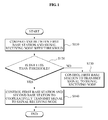
- FIG. 1 illustrates an exemplary method for controlling signal transmission.
- a signal to noise ratio (SNR) between a first base station and a signal receiving node is compared with a threshold.
- the SNR may be a long-term average SNR.
- the first base station In response to the SNR not being less than the threshold, the first base station is controlled to transmit a signal to the signal receiving node in operation S 130 .
- the first base station and a second base station are controlled to cooperatively transmit a signal to the signal receiving node in operation S 140 .
- the second base station may be included in an adjacent cell to a cell including the first base station.
- Operation S 140 may further include transmitting of channel information about the signal receiving node to the second base station.
- the first base station and the second base station may transmit the signal to the signal receiving node according to Zero Forcing Beamforming (ZFBF).
- ZFBF Zero Forcing Beamforming
- FIG. 2 illustrates an exemplary communication system.
- a base station ( 1 ) 210 a base station ( 2 ) 220 , a signal receiving node ( 1 ) 231 , a signal receiving node ( 2 ) 232 , and a signal receiving node ( 3 ) 233 are illustrated.
- the signal receiving node ( 1 ) 231 is included in a coverage of the base station ( 1 ) 210 and a long-term average SNR exceeds a threshold.
- the signal receiving node ( 2 ) 232 is included in a coverage of the base station ( 1 ) 210 and a coverage of the base station ( 2 ) 220 , a service node corresponds to the base station ( 1 ) 210 , and the long-term average SNR is less than the threshold.
- the signal receiving node ( 3 ) 233 is included in the coverage of the base station ( 2 ) 220 and the long-term average SNR exceeds the threshold.
- the long-term average SNR between the base station ( 1 ) 210 and the signal receiving node ( 1 ) 231 is compared with the threshold in operation S 110 .
- the base station ( 1 ) 210 In response to the long-term average SNR of the signal receiving node ( 1 ) 231 exceeding the threshold, the base station ( 1 ) 210 is controlled to transmit a signal to the signal receiving node ( 1 ) 231 in operation S 130 .
- the base station ( 1 ) 210 and the base station ( 2 ) 220 are controlled to cooperatively transmit a signal to the signal receiving node ( 2 ) 232 in operation S 140 .
- operation S 140 may include transmitting of channel information about the signal receiving node ( 2 ) 232 to the base station ( 2 ) 220 since the base station ( 2 ) 220 does not receive channel information from the signal receiving node ( 2 ) 232 .
- the controlling of signal transmission in the base station ( 1 ) 210 has been described hereto, and operations of controlling signal transmission in the base station ( 2 ) 220 are identical to those of the base station ( 1 ) 210 .
- the long-term average SNR between the base station ( 2 ) 220 and the signal receiving node ( 3 ) 233 is compared with the threshold in operation S 110 .
- the base station ( 2 ) 220 In response to the long-term average SNR of the signal receiving node ( 3 ) 233 exceeding the threshold, the base station ( 2 ) 220 is controlled to transmit the signal to the signal receiving node ( 3 ) 233 in operation S 130 .
- the communication system illustrated in FIG. 2 may be a communication system based on a multiple-input and multiple output (MIMO) scheme, and the base station ( 1 ) 210 and the base station ( 2 ) 220 may transmit a signal according to the ZFBF.
- MIMO multiple-input and multiple output
- the method for controlling signal transmission compares a long-term average SNR between a base station and a signal receiving node with a threshold, and enables both the base station and another base station located in an adjacent cell to cooperatively transmit a signal to the signal receiving node where the long-term average SNR is less than the threshold, and co-channel interference (CCI) of the signal receiving node located in a cell edge is removed. Accordingly, effective signal transmission may be realized. Where the long-term average SNR is not less than the threshold, only the base station is controlled to transmit the signal to the signal receiving node. Accordingly, inter-user interference (IUI) that occurs in the signal receiving node located around a center of a cell due to the cooperative signal transmission may be prevented.
- IUI inter-user interference
- FIG. 3 illustrates another exemplary method for controlling signal transmission.
- a first data rate with respect to a signal receiving node of a first base station and a second data rate according to the cooperative signal transmission may be calculated, where the first base station and the second base station cooperatively transmit the signal to the signal receiving node.
- the second base station may be included in an adjacent cell to a cell including the first base station.
- the operation S 310 may further include calculating of the first data rate and the second data rate.
- a network channel matrix is calculated with respect to a network channel, formed in a network which includes the first base station and the second base station, using a long-term average SNR between the first base station and a plurality of signal receiving nodes, a long-term average SNR between the second base station and the plurality of signal receiving nodes, and using a channel matrix with respect to a channel formed between the first base station and the plurality of signal receiving nodes and the second base station and the plurality of signal receiving nodes.
- the method for controlling signal transmission may further include an operation of detecting a first received signal of the signal receiving node, where IUI, CCI and a noise are utilized, via calculation based on the ZFBF matrix and the network channel matrix, the ZFBF matrix including a ZFBF matrix with respect to a signal receiving node of the first base station a ZFBF matrix with respect to a signal receiving node of the second base station.
- the method for controlling signal transmission may include operations of calculating a first signal to interference plus noise ratio (SINR) of the signal receiving node based on the first received signal, and calculating the first data rate using the first SINR.
- SINR signal to interference plus noise ratio
- the method for controlling signal transmission may include an operation of detecting a second received signal in the signal receiving node.
- the IUI and the noise are utilized via the calculation based on ZFBF with respect to the network channel matrix and via the calculation with respect to the network channel.
- the method for controlling signal transmission may include operations of calculating a second SINR of the signal receiving node based on the second received signal, and calculating the second data rate using the second SINR.
- FIG. 4 illustrates another exemplary communication system.
- a base station ( 1 ) 410 a base station ( 2 ) 420 , a signal receiving node ( 1 ) 431 , and a signal receiving node ( 2 ) 432 are illustrated.
- a number of the base station ( 1 ) 410 and the base station ( 2 ) 420 are respectively two, a number of the signal receiving node ( 1 ) 431 and the signal receiving node ( 2 ) 432 are respectively one, and the communication system illustrated in FIG. 4 is a communication system based on a multi-user MIMO scheme.
- H 1 is a channel matrix formed between the base station ( 1 ) 410 and the signal receiving node ( 1 ) 431
- H 2 is a channel matrix formed between the base station ( 2 ) 420 and the signal receiving node ( 1 ) 431
- G 1 is a channel matrix formed between the base station ( 2 ) 420 and the signal receiving node ( 2 ) 432
- G 2 is a channel matrix formed between the base station ( 1 ) 410 and the signal receiving node ( 2 ) 432 .
- a long-term average SNR between the base station ( 1 ) 410 and the signal receiving node ( 1 ) 431 and a long-term average SNR between the base station ( 2 ) 420 and the signal receiving node ( 2 ) 432 are ⁇ 1
- a long-term average SNR between the base station ( 1 ) 410 and the signal receiving node ( 2 ) 432 and a long-term average SNR between the base station ( 2 ) 420 and the signal receiving node ( 1 ) 431 are ⁇ 2 .
- the network channel matrix H of a network including the base station ( 1 ) 410 and the base station ( 2 ) 420 may be represented by,
- the signal receiving node ( 1 ) 431 and the signal receiving node ( 2 ) 432 transmit channel information to the base station ( 1 ) 410 and to the base station ( 2 ) 420 in limited feedback environments, a quantized error occurs between channel information received in an actual channel and channel information received in the base station ( 1 ) 410 and the base station ( 2 ) 420 . Therefore, the network channel matrix ⁇ where the quantized error is utilized may be represented by,
- H ⁇ [ ⁇ 1 ⁇ H ⁇ 1 ⁇ 2 ⁇ H ⁇ 2 ⁇ 2 ⁇ G ⁇ 2 ⁇ 1 ⁇ G ⁇ 1 ] [ Equation ⁇ ⁇ 2 ]
- the first data rate may be calculated using a ZFBF matrix with respect to the signal receiving node ( 1 ) 431 of the base station ( 1 ) 410 and a ZFBF matrix with respect to the signal receiving node ( 2 ) 432 of the base station ( 2 ) 420 .
- the ZFBF matrix T using and ⁇ 1 may be represented by,
- Received signals y of the signal receiving node ( 1 ) 431 and the signal receiving node ( 2 ) 432 may be detected via calculation of Equation 4 based on the ZFBF matrix shown in Equation 3 and the network channel matrix shown in Equation 2.
- [ x ( 1 ) x ( 2 ) ] indicates a signal transmitted from each of the base station ( 1 ) 410 and the base station ( 2 ) 420 ,
- AWGN additive White Gaussian Noise
- received signals y k received in each of the signal receiving node ( 1 ) 431 and the signal receiving node ( 2 ) 432 may be represented by,
- the received signals received in each of the signal receiving node ( 1 ) 431 and the signal receiving node ( 2 ) 432 include IUI, CCI and a noise.
- an SINR of the signal receiving node ( 1 ) 431 and the signal receiving node ( 2 ) 432 may be calculated using the received signals.
- the SINR may be represented by,
- first data rates with respect to the signal receiving node ( 1 ) 431 of the base station ( 1 ) 410 and first data rates with respect to the signal receiving node ( 2 ) 432 of the base station ( 2 ) 420 may be calculated based on the SINR.
- R S ?? [ ⁇ k ⁇ log ⁇ ( 1 + S ⁇ ⁇ I ⁇ ⁇ N ⁇ ⁇ R k ( 1 ) ) ] . [ Equation ⁇ ⁇ 7 ]
- the calculating of the first data rate has been described above.
- the calculating of a second data rate is further described.
- the second data rate may be calculated using the network channel matrix shown in Equation 2 and the ZFBF matrix with respect to the network channel.
- received signals y of the signal receiving node ( 1 ) 431 and the signal receiving node ( 2 ) 432 may be detected using Equation 9.
- the signal receiving node ( 1 ) 431 and the signal receiving node ( 2 ) 432 receive signals, cooperatively transmitted from the base station ( 1 ) 410 and the base station ( 2 ) 420 , received signals of the signal receiving node ( 1 ) 431 and the signal receiving node ( 2 ) 432 are identical with each other as shown in Equation 9.
- an SINR of the signal receiving node ( 1 ) 431 and the signal receiving node ( 2 ) 432 may be calculated using Equation 10.
- the second data rates may be calculated by calculating the Ergodic sum-rate R c with respect to the signal receiving node ( 1 ) 431 and the signal receiving node ( 2 ) 432 according to Equation 11.
- R c 1 2 ⁇ ?? [ ⁇ k ⁇ log ⁇ ( 1 + S ⁇ ⁇ I ⁇ ⁇ N ⁇ ⁇ R k ) ] . [ Equation ⁇ ⁇ 11 ]
- the calculating of the first data rate and the second data rate is described in detail hereto.
- the method for controlling signal transmission according to an exemplary embodiment is further described with reference to FIG. 3 .
- the first base station In response to the second data rate not exceeding the first data rate, the first base station is controlled to transmit a signal to a signal receiving node in operation S 330 .
- the first base station and the second base station are controlled to cooperatively transmit a signal to the signal receiving node in operation S 340 .
- operation S 340 may include transmitting of channel information about the signal receiving node to the second base station.
- the first base station and the second base station may transmit the signal to the signal receiving node according to ZFBF.
- the signal receiving node ( 1 ) 231 is included in a coverage of the base station ( 1 ) 210 , the first data rate exceeds the second data rate.
- the signal receiving node ( 2 ) 232 may be included in a coverage of the base station ( 1 ) 210 and a coverage of the base station ( 2 ) 220 , the base station ( 1 ) 210 corresponds to a service node, and the second data rate exceeds the first data rate.
- the signal receiving node ( 3 ) 233 is included in a coverage of the base station ( 2 ) 220 and the first data rate exceeds the second data rate.
- the first data rate when the base station ( 1 ) 210 transmits the signal to the signal receiving node ( 1 ) 231 and the second data rate when the base station ( 2 ) 220 and the base station a 210 cooperatively transmit the signal to the signal receiving node ( 1 ) 231 are calculated in operation S 310 .
- the base station ( 1 ) 210 In response to the first data rate exceeding the second data rate, the base station ( 1 ) 210 is controlled to transmit the signal to the signal receiving node ( 1 ) 231 in operation S 330 .
- a first data rate when the base station ( 1 ) 210 transmits a signal to the signal receiving node ( 2 ) 232 and a second data rate when the base station ( 1 ) 210 and the base station ( 2 ) 220 cooperatively transmit a signal to the signal receiving node ( 2 ) 232 are calculated in operation S 310 .
- the base station ( 1 ) 210 and the base station ( 2 ) 220 are controlled to cooperatively transmit a signal to the signal receiving node ( 2 ) 232 in operation S 340 .
- operation S 340 may include transmitting of the channel information about the signal receiving node ( 2 ) 232 to the base station ( 2 ) 220 since the base station ( 2 ) 220 does not receive channel information from the signal receiving node ( 2 ) 232 .
- the controlling of signal transmission in the base station ( 1 ) 210 has been described hereto, and the controlling of signal transmission in the base station ( 2 ) 220 is identical to the controlling of signal transmission in the base station ( 1 ) 210 .
- a first data rate when the base station ( 2 ) 220 transmits a signal to the signal receiving node ( 3 ) 233 and a second data rate when the base station ( 2 ) 220 and the base station ( 1 ) 210 cooperatively transmit a signal to the signal receiving node ( 3 ) 233 are calculated in operation S 310 .
- the base station ( 2 ) 220 In response to the first data rate exceeding the second data rate, the base station ( 2 ) 220 is controlled to transmit the signal to the signal receiving node ( 3 ) 233 in operation S 330 .
- the communication system illustrated in FIG. 2 may be a communication system based on a multi-user MIMO scheme, and, the first base station ( 1 ) 210 and the second base station 220 may transmit the signal according to ZFBF.
- the method for controlling signal transmission calculates a first data rate and a second data rate with respect to a signal receiving node, and, where the second data rate exceeds the first data rate, a base station, and another base station located in an adjacent cell to the base station cooperatively transmit a signal to the signal receiving node. Accordingly, effective transmission may be realized by removing CCI in the signal receiving node located in a cell edge. Where the second data rate does not exceed the first data rate, only the base station transmits the signal to the signal receiving node. Accordingly, IUI may be prevented from getting larger due to cooperative signal transmission.
- the methods for controlling signal transmission as described above may be recorded, stored, or fixed in one or more computer-readable media including program instructions to cause a processor to implement or carry out various operations embodied by a computer to form a specific machine or apparatus.
- computer-readable media may include magnetic media such as hard disks, floppy disks, and magnetic tape; optical media such as CD ROM disks and DVDs; magneto-optical media such as optical disks; and hardware devices that are specially configured to store and perform program instructions, such as read-only memory (ROM), random access memory (RAM), flash memory, and the like.
- program instructions may include both steps, procedures, instructions embodied in machine code, such as produced by a compiler, and files containing higher level code that may be executed by the computer using an interpreter or other programming.
- Such hardware devices may be configured to act as one or more software modules in order to perform the exemplary method described above, or vice-versa.
- FIG. 5 illustrates an exemplary apparatus for controlling signal transmission.
- an apparatus 510 for controlling signal transmission, a first base station 520 , and a second base station 530 are illustrated.
- the apparatus 510 for controlling signal transmission may include a determination unit 511 and a control unit 512 .
- the determination unit 511 may determine whether an SNR between a first base station 520 and a signal receiving node (not shown) is less than a threshold.
- the SNR may be a long-term average SNR.
- the control unit 512 may control the first base station 520 and a second base station 530 to cooperatively transmit a signal to the signal receiving node when the SNR is less than the threshold.
- control unit 512 may transmit channel information about the signal receiving node to the second base station 530 when the SNR is less than the threshold.
- control unit 512 may control the first base station 520 to transmit the signal to the signal receiving node when the SNR is not less than the threshold.
- the first base station 520 and the second base station 530 may transmit the signal to the signal receiving node according to ZFBF.
Abstract
Description
indicates a signal transmitted from each of the base station (1) 410 and the base station (2) 420,
indicates an additive White Gaussian Noise (AWGN).
T=Ĥ H(ĤĤ H)−1Σ. [Equation 8]
Claims (16)
Applications Claiming Priority (2)
| Application Number | Priority Date | Filing Date | Title |
|---|---|---|---|
| KR1020080094725A KR101469152B1 (en) | 2008-09-26 | 2008-09-26 | Method and appratus for controlling signal transmission |
| KR10-2008-0094725 | 2008-09-26 |
Publications (2)
| Publication Number | Publication Date |
|---|---|
| US20100081424A1 US20100081424A1 (en) | 2010-04-01 |
| US8897765B2 true US8897765B2 (en) | 2014-11-25 |
Family
ID=42058003
Family Applications (1)
| Application Number | Title | Priority Date | Filing Date |
|---|---|---|---|
| US12/417,675 Active 2032-07-03 US8897765B2 (en) | 2008-09-26 | 2009-04-03 | Method and appratus for controlling signal transmission |
Country Status (2)
| Country | Link |
|---|---|
| US (1) | US8897765B2 (en) |
| KR (1) | KR101469152B1 (en) |
Cited By (1)
| Publication number | Priority date | Publication date | Assignee | Title |
|---|---|---|---|---|
| US20190014581A1 (en) * | 2010-12-02 | 2019-01-10 | Interdigital Patent Holdings, Inc. | Method and apparatus for minimizing interference at a mobile station using a shared node |
Families Citing this family (6)
| Publication number | Priority date | Publication date | Assignee | Title |
|---|---|---|---|---|
| US8331974B1 (en) * | 2008-08-05 | 2012-12-11 | Sprint Communications Company L.P. | Control of power level commands in wireless devices |
| KR101644097B1 (en) | 2010-12-21 | 2016-08-01 | 삼성전자주식회사 | Communication method for neighboring terminal and target terminal |
| CN102685796A (en) * | 2011-03-08 | 2012-09-19 | 中国移动通信集团公司 | Method and system for transmitting and receiving control information, base station and terminal |
| KR101687047B1 (en) * | 2012-08-22 | 2016-12-15 | 한국전자통신연구원 | Adaptive coding modulation apparatus and method of forward link in satellite communication |
| JP6151074B2 (en) * | 2013-04-15 | 2017-06-21 | 京セラ株式会社 | Communication system and communication control method |
| US9497680B1 (en) * | 2015-06-18 | 2016-11-15 | Amazon Technologies, Inc. | Frequency acquisition during roaming |
Citations (13)
| Publication number | Priority date | Publication date | Assignee | Title |
|---|---|---|---|---|
| US5276703A (en) * | 1992-01-13 | 1994-01-04 | Windata, Inc. | Wireless local area network communications system |
| KR20040091671A (en) | 2002-02-26 | 2004-10-28 | 퀄컴 인코포레이티드 | Multiple-input, multiple-output (mimo) systems with multiple transmission modes |
| KR20060135162A (en) | 2005-06-24 | 2006-12-29 | 삼성전자주식회사 | User selection method in zero forcing beamforming algorithm |
| US20070041345A1 (en) * | 2005-08-17 | 2007-02-22 | Yarvis Mark D | Methods and apparatus for providing an integrated multi-hop routing and cooperative diversity system |
| US20070147414A1 (en) | 2005-12-22 | 2007-06-28 | Samsung Electronics Co., Ltd. | Method of switching transmission modes in IEEE 802.11n MIMO communication systems |
| US7308268B2 (en) * | 2005-11-14 | 2007-12-11 | Societe Francaise Du Radiotelephone | Method and system for simulation and management of the resources of a mobile telephone network |
| US20080132262A1 (en) * | 2006-10-26 | 2008-06-05 | Samsung Electronics Co., Ltd. | Base station cooperation method in communication system and system for the same |
| US20080233968A1 (en) | 2007-03-14 | 2008-09-25 | Samsung Electronics Co., Ltd. | Apparatus and method for downlink scheduling in a multi antenna wireless communication system |
| US20080240018A1 (en) * | 2007-03-29 | 2008-10-02 | Feng Xue | Dynamic multi-access relaying for wireless networks |
| US20100009710A1 (en) * | 2008-07-10 | 2010-01-14 | Nec Laboratories America, Inc. | Distributed inter-cell interference mitigation in ofdma multi-carrier wireless data networks |
| US20100098014A1 (en) * | 2003-12-23 | 2010-04-22 | Telefonaktiebolaget Lm Ericsson (Publ) | Advanced multi-sensor processing |
| US20100157901A1 (en) * | 2007-06-18 | 2010-06-24 | Sanderovitz Amichay | Wireless network architecture and method for base station utilization |
| US20100303032A1 (en) * | 2007-11-29 | 2010-12-02 | Electronics And Telecommunications Research Institute | Method and system for operating cooperative receiving diversity scheme and selective cooperative relaying |
-
2008
- 2008-09-26 KR KR1020080094725A patent/KR101469152B1/en active IP Right Grant
-
2009
- 2009-04-03 US US12/417,675 patent/US8897765B2/en active Active
Patent Citations (13)
| Publication number | Priority date | Publication date | Assignee | Title |
|---|---|---|---|---|
| US5276703A (en) * | 1992-01-13 | 1994-01-04 | Windata, Inc. | Wireless local area network communications system |
| KR20040091671A (en) | 2002-02-26 | 2004-10-28 | 퀄컴 인코포레이티드 | Multiple-input, multiple-output (mimo) systems with multiple transmission modes |
| US20100098014A1 (en) * | 2003-12-23 | 2010-04-22 | Telefonaktiebolaget Lm Ericsson (Publ) | Advanced multi-sensor processing |
| KR20060135162A (en) | 2005-06-24 | 2006-12-29 | 삼성전자주식회사 | User selection method in zero forcing beamforming algorithm |
| US20070041345A1 (en) * | 2005-08-17 | 2007-02-22 | Yarvis Mark D | Methods and apparatus for providing an integrated multi-hop routing and cooperative diversity system |
| US7308268B2 (en) * | 2005-11-14 | 2007-12-11 | Societe Francaise Du Radiotelephone | Method and system for simulation and management of the resources of a mobile telephone network |
| US20070147414A1 (en) | 2005-12-22 | 2007-06-28 | Samsung Electronics Co., Ltd. | Method of switching transmission modes in IEEE 802.11n MIMO communication systems |
| US20080132262A1 (en) * | 2006-10-26 | 2008-06-05 | Samsung Electronics Co., Ltd. | Base station cooperation method in communication system and system for the same |
| US20080233968A1 (en) | 2007-03-14 | 2008-09-25 | Samsung Electronics Co., Ltd. | Apparatus and method for downlink scheduling in a multi antenna wireless communication system |
| US20080240018A1 (en) * | 2007-03-29 | 2008-10-02 | Feng Xue | Dynamic multi-access relaying for wireless networks |
| US20100157901A1 (en) * | 2007-06-18 | 2010-06-24 | Sanderovitz Amichay | Wireless network architecture and method for base station utilization |
| US20100303032A1 (en) * | 2007-11-29 | 2010-12-02 | Electronics And Telecommunications Research Institute | Method and system for operating cooperative receiving diversity scheme and selective cooperative relaying |
| US20100009710A1 (en) * | 2008-07-10 | 2010-01-14 | Nec Laboratories America, Inc. | Distributed inter-cell interference mitigation in ofdma multi-carrier wireless data networks |
Non-Patent Citations (3)
| Title |
|---|
| Chae, Chan-Byoung et al., "Coordinated Beamforming with Limited Feedback in the MIMO Broadcast Channel," 11 pages, Oct. 2008, appears in Selected Areas in Communications, IEEE Journal on, vol. 26, Issue 8, as pp. 1505-1515. |
| Korean Office Action issued Jun. 26, 2014 in counterpart Korean Patent Application No. 10-2008-0094725 (7 pages, in Korean with English Translation). |
| Shin, Young-il et al., "Multi-antenna Subcarrier Allocation Using Zero-Forcing Beamfroming in MIMO-OFDM Systems," Oct. 2007, pp. 974-983, Journal of Korean Information and Communication Society. (T5: English Abstract Only). |
Cited By (1)
| Publication number | Priority date | Publication date | Assignee | Title |
|---|---|---|---|---|
| US20190014581A1 (en) * | 2010-12-02 | 2019-01-10 | Interdigital Patent Holdings, Inc. | Method and apparatus for minimizing interference at a mobile station using a shared node |
Also Published As
| Publication number | Publication date |
|---|---|
| KR20100035369A (en) | 2010-04-05 |
| US20100081424A1 (en) | 2010-04-01 |
| KR101469152B1 (en) | 2014-12-05 |
Similar Documents
| Publication | Publication Date | Title |
|---|---|---|
| US8897765B2 (en) | Method and appratus for controlling signal transmission | |
| US9124313B2 (en) | Multi-cell cooperative communication system and terminal device | |
| US8064823B2 (en) | Apparatus, method and computer program product for determining transmit weights in relay networks | |
| EP2062378B1 (en) | Beamforming with imperfect channel state information | |
| US7689177B2 (en) | Method and apparatus for transmitting/receiving feedback information and system supporting the same in a multi-user multi-antenna system | |
| US8359042B2 (en) | Communication system and method of performing interference control using random beamforming technique | |
| EP2526626B1 (en) | Communication apparatus and precoding method based on multiple cells and multiple users | |
| US9078151B2 (en) | Link performance abstraction method and apparatus in a wireless communication system | |
| US8254830B2 (en) | Data transmission system for forwarding data using a plurality of antennas | |
| US8107550B2 (en) | Methods for precoding signals for transmission in wireless MIMO system | |
| KR101470501B1 (en) | Apparatus and method for transmitting data based on quantized channel state information | |
| US7916620B2 (en) | Multi-user data transmission/reception system and mode determination method | |
| US7940690B2 (en) | Apparatus and method for determining transmission mode in wireless communication system | |
| US8416877B2 (en) | Unitary precoding apparatus and method in multi-user multiple input multiple output (MIMO) communication system | |
| KR101290918B1 (en) | Communication system for using interference alignment scheme in multicell environment | |
| Zhang et al. | Rate adaptation for downlink massive MIMO networks and underlaid D2D links: A learning approach | |
| US20140226520A1 (en) | Method for coordinating interference in an uplink interference channel for a terminal in a wireless communication system | |
| US10063396B2 (en) | Method and apparatus of topological pilot decontamination for massive MIMO systems | |
| US9301263B2 (en) | Method for determining transmission power in MIMO system based on cooperative transmission | |
| US20100266056A1 (en) | Method and apparatus for scheduling multiple users in a multiple-input multiple-output system | |
| KR101906918B1 (en) | Apparatus and method for uplink scheduling in tdd cellular network | |
| US20150256317A1 (en) | Method and apparatus for adaptive channel direction information feedback in a heterogeneous system | |
| KR101642977B1 (en) | Method and apparatus of codebook transformation for interference mitigation in codebook-based MIMO precoding | |
| Kang et al. | Outage analysis of multi-antenna rate adaptive systems with outdated feedback | |
| HARA | Time slot assignment algorithms for SDMA/TDMA system based on estimated SINR |
Legal Events
| Date | Code | Title | Description |
|---|---|---|---|
| AS | Assignment |
Owner name: SAMSUNG ELECTRONICS CO., LTD.,KOREA, REPUBLIC OF Free format text: ASSIGNMENT OF ASSIGNORS INTEREST;ASSIGNORS:SUH, JUNG HOON;PARK, KI-HONG;KO, YOUNG-CHAI;AND OTHERS;REEL/FRAME:022509/0083 Effective date: 20090310 Owner name: KOREA UNIVERSITY INDUSTRIAL & ACADEMIC COLLABORATI Free format text: ASSIGNMENT OF ASSIGNORS INTEREST;ASSIGNORS:SUH, JUNG HOON;PARK, KI-HONG;KO, YOUNG-CHAI;AND OTHERS;REEL/FRAME:022509/0083 Effective date: 20090310 Owner name: SAMSUNG ELECTRONICS CO., LTD., KOREA, REPUBLIC OF Free format text: ASSIGNMENT OF ASSIGNORS INTEREST;ASSIGNORS:SUH, JUNG HOON;PARK, KI-HONG;KO, YOUNG-CHAI;AND OTHERS;REEL/FRAME:022509/0083 Effective date: 20090310 |
|
| STCF | Information on status: patent grant |
Free format text: PATENTED CASE |
|
| MAFP | Maintenance fee payment |
Free format text: PAYMENT OF MAINTENANCE FEE, 4TH YEAR, LARGE ENTITY (ORIGINAL EVENT CODE: M1551) Year of fee payment: 4 |
|
| MAFP | Maintenance fee payment |
Free format text: PAYMENT OF MAINTENANCE FEE, 8TH YEAR, LARGE ENTITY (ORIGINAL EVENT CODE: M1552); ENTITY STATUS OF PATENT OWNER: LARGE ENTITY Year of fee payment: 8 |