US8881916B2 - Vertical cable manager - Google Patents
Vertical cable manager Download PDFInfo
- Publication number
- US8881916B2 US8881916B2 US12/814,900 US81490010A US8881916B2 US 8881916 B2 US8881916 B2 US 8881916B2 US 81490010 A US81490010 A US 81490010A US 8881916 B2 US8881916 B2 US 8881916B2
- Authority
- US
- United States
- Prior art keywords
- door
- hinge pin
- pair
- guide surface
- opening
- Prior art date
- Legal status (The legal status is an assumption and is not a legal conclusion. Google has not performed a legal analysis and makes no representation as to the accuracy of the status listed.)
- Active, expires
Links
Images


Classifications
-
- H—ELECTRICITY
- H04—ELECTRIC COMMUNICATION TECHNIQUE
- H04Q—SELECTING
- H04Q1/00—Details of selecting apparatus or arrangements
- H04Q1/02—Constructional details
- H04Q1/06—Cable ducts or mountings specially adapted for exchange installations
- H04Q1/062—Cable ducts or mountings specially adapted for exchange installations vertical management arrangements
-
- H—ELECTRICITY
- H04—ELECTRIC COMMUNICATION TECHNIQUE
- H04Q—SELECTING
- H04Q1/00—Details of selecting apparatus or arrangements
- H04Q1/02—Constructional details
- H04Q1/06—Cable ducts or mountings specially adapted for exchange installations
- H04Q1/066—Cable ducts or mountings specially adapted for exchange installations arranged on the front side
-
- H—ELECTRICITY
- H04—ELECTRIC COMMUNICATION TECHNIQUE
- H04Q—SELECTING
- H04Q1/00—Details of selecting apparatus or arrangements
- H04Q1/02—Constructional details
- H04Q1/06—Cable ducts or mountings specially adapted for exchange installations
- H04Q1/068—Cable ducts or mountings specially adapted for exchange installations arranged on the rear side
-
- H—ELECTRICITY
- H04—ELECTRIC COMMUNICATION TECHNIQUE
- H04Q—SELECTING
- H04Q1/00—Details of selecting apparatus or arrangements
- H04Q1/02—Constructional details
- H04Q1/13—Patch panels for monitoring, interconnecting or testing circuits, e.g. patch bay, patch field or jack field; Patching modules
-
- H—ELECTRICITY
- H04—ELECTRIC COMMUNICATION TECHNIQUE
- H04Q—SELECTING
- H04Q2201/00—Constructional details of selecting arrangements
- H04Q2201/02—Details of frames
Definitions
- the present invention is directed to a cable management device and, more particularly, a vertical cable manager having a dual hinging door for managing cable on the front and/or the rear of any EIA network equipment rack.
- a cable manager includes a backbone, a plurality of finger sections connected to the backbone to form a vertical cable channel, and a first pair of horizontal rails connected to the top end of the backbone and a second pair of horizontal rails connected to the bottom end of the backbone.
- the cable manager also includes a first cross brace connected to the first pair of horizontal rails and a second cross brace connected to the second pair of horizontal rails, and a door hingedly connected to the first and second cross braces.
- Each cross brace includes a mounting surface having a plurality of guide surfaces and an alignment aid protruding from the mounting surface and extending beyond a horizontal axis extending between the guide surfaces.
- the door includes a pair of latches connected to a hinge pin through a pair of windows, and a spring connected to the hinge pin and the pair of latches.
- the cable manager includes a third cross brace connected to the first pair of horizontal rails and a fourth cross brace connected to the second pair of horizontal rails.
- a second door is hingedly connected to the third and fourth cross braces.
- each cross brace includes a mounting surface having a plurality of apertures that receive a hinge pin when the door is in a closed position.
- the hinge pins are removed from the mounting surface apertures upon actuation of a pair of latches.
- each finger section is connected to each side of the backbone to form a front vertical cable channel.
- four finger sections are connected to each side of the backbone to form a rear vertical cable channel.
- each finger section includes eleven fingers connected to a base, and each finger can be removed from the base to provide a horizontal pathway into the front or rear vertical cable channel.
- the door includes a first pair of latches connected to a first hinge pin through a first pair of windows, and a second pair of latches connected to a second hinge pin through a second pair of windows.
- the door includes a first spring connected to the first hinge pin and the first pair of latches, and a second spring connected to the second hinge pin and the second pair of latches.
- the first pair of latches and the second pair of latches are vertically positioned near a longitudinal midpoint of the door.
- FIG. 1 is a front right perspective view of a vertical cable manager positioned between two telecommunications racks according to the present invention, showing a hinged door in the closed position;
- FIG. 2 is a front right perspective view of the vertical cable manager of FIG. 1 , showing the hinged door in an open position;
- FIG. 3 is an enlarged top view of the vertical cable manager of FIG. 1 ;
- FIG. 4 is a partial enlarged top view of the vertical cable manager of FIG. 2 ;
- FIG. 5 is a cross-sectional view taken along lines 5 - 5 of FIG. 1 ;
- FIG. 6 is an enlarged view of a center section of the hinged door of FIG. 2 ;
- FIG. 7 is an enlarged view of a top section of the hinged door of FIG. 2 , showing the hinged door in an open position;
- FIG. 8 is an enlarged view of a bottom section of the hinged door of FIG. 2 , showing the hinged door in an open position;
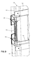
- FIG. 9 is an enlarged view of a center section of the hinged door of FIG. 6 ;
- FIG. 10 is an exploded view of the hinged door of FIG. 9 ;
- FIG. 11 is an enlarged view of the top section of the hinged door of FIG. 7 ;
- FIG. 12 is an enlarged view of the bottom section of the hinged door of FIG. 8 ;
- FIG. 13 is a cross-sectional view taken along lines 13 - 13 of FIG. 1 , showing the hinged door in a closed position;
- FIG. 14 is a cross-sectional view taken along lines 14 - 14 of FIG. 13 ;
- FIG. 15 is an enlarged view of the center section of the hinged door similar to FIG. 9 , showing actuation of the door latches;
- FIG. 16 is a cross-sectional view similar to FIG. 13 , showing the hinged door in an open position;
- FIG. 17 is an enlarged view of a top section of the vertical cable manager of FIG. 2 , showing a finger removed from a finger section;
- FIG. 18 is an enlarged perspective view of a finger section of the vertical cable manager of FIG. 1 ;
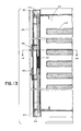
- FIG. 19A is an enlarged view of a portion of the finger section of FIG. 18 ;
- FIG. 19B is an enlarged view of a portion of the finger section of FIG. 18 , showing a finger removed from the finger section.
- Vertical cable manager 20 may be used to manage cable (not shown) on the front and/or the rear of any EIA network equipment rack, such as rack 21 .
- Rack 21 may include a patch panel such as angled patch panel 23 or other active equipment such as a switch.
- FIGS. 1-19B illustrate vertical cable manager 20 used to manage cable on the front and the rear of rack 21 , it is likewise contemplated that vertical cable manager 20 may be used to manage cable only on the front of rack 21 .
- Vertical cable manager 20 includes a backbone 22 , a plurality of cross braces such as cross brace 24 connected to a plurality of horizontal rails such as horizontal rail 25 , a plurality of finger sections such as finger section 26 connected to backbone 22 and two hinged doors such as hinged door 28 connected to cross braces 24 , which collectively define a front vertical cable channel 30 and a rear vertical cable channel 31 .
- vertical cable manager 20 includes four cross braces 24 , sixteen finger sections 26 and two hinged doors 28 for front and rear cable management.
- Vertical cable manager 20 would include only two cross braces 24 , eight finger sections 26 and one hinged door 28 for front cable management.
- FIGS. 1 and 5 show doors 28 in a closed position, while FIGS. 2 and 4 show front door 28 in an open position.
- backbone 22 extends the entire height of vertical cable manager 20 .
- FIG. 3 shows backbone 22 configured to provide greater front cable capacity, backbone 22 may be configured to provide equal front and rear cable capacity. Similarly, backbone 22 may be configured to provide greater rear cable capacity.
- Backbone 22 includes multiple groups of slots for receiving four slack spools 32 .
- slack spools 32 are plastic and snap onto backbone 22 .
- FIG. 2 shows four slack spools 32 equidistantly-spaced along the height of vertical cable manager 20 , slack spools 32 may be removed and repositioned to accommodate a variety of slack cable lengths.
- backbone 22 includes a plurality of pass through openings 34 having rolled edges 35 , which are formed using a special rollover tool that provides cable protection without the need for a separate plastic or rubber piece.
- backbone 22 includes twelve pass through openings 34 , as best seen in FIG. 2 .
- cross brace 24 includes a mounting surface 36 having hinge pin holes 38 , guide surfaces 40 and a door alignment or closure aid 42 .
- Hinge pin holes 38 are integrated into cross brace 24 to ensure pin alignment during door actuation. Due to the door weight and clearance between hinge pin 44 and hinge pin hole 38 , gravity may cause the released side of door 28 to drop below mounting surface 36 of cross brace 24 and cause door 28 to bang on the abrupt guide surface 40 of hinge pin hole 38 upon closure.
- door alignment or closure aid 42 protrudes beyond a horizontal axis extending between guide surfaces 40 .
- Door alignment or closure aid 42 takes advantage of the additional space in the middle of door 28 to provide a more gradual lead-in, helping to lift door 28 before door 28 abruptly contacts guide surface 40 of hinge pin hole 38 .
- door alignment or closure aid 42 assists the alignment and engagement of hinge pin 44 into hinge pin hole 38 in cross brace 24 .
- FIG. 1 shows two sets of door latches 46 , 48 utilized in door 28 .
- One latch from each set of latches 46 , 48 may be squeezed together to actuate door 28 as shown in FIGS. 15 and 16 , thus allowing door 28 to hinge in either direction.
- FIG. 2 shows door 28 opening to the left, it is likewise contemplated that door 28 may open to the right.
- FIGS. 9 and 10 show return spring 50 utilized in door 28 , with door skin 60 (see FIG. 6 ) removed for clarity. Window 58 in door skin 60 provides the necessary clearance for latches 46 , 48 to slide during door actuation.
- Latch stop surface 52 of spring support door bracket 54 provides support for latches 46 , 48 when door 28 is closed, as best seen in FIG. 6 .
- FIG. 10 shows an exploded view of the components of the door latch mechanism.
- hinge pins 44 are inserted through hinge pin holes 38 until grooves 45 are aligned with latches 46 , 48 , and then latches 46 , 48 are snapped onto hinge pins 44 .
- Return spring 50 is inserted over one end of hinge pin 44 , compressed, and then inserted onto the other end of hinge pin 44 .
- FIGS. 11 and 12 illustrate hinge pins 44 positioned within hinge pin holes 38 on the top and bottom of door 28 , respectively, and FIGS. 7 and 8 illustrate the top and bottom of door 28 connected to cross braces 24 .
- FIGS. 13 and 14 show door 28 in a closed position; whereas, FIG. 16 shows door 28 in an open position.
- FIG. 17 shows a finger removed from finger section 26 shown in FIG. 18 .
- vertical cable manager 20 includes four fingers sections 26 on each side of front vertical cable channel 30 , and four finger sections on each side of rear vertical cable channel 31 .
- each finger section 26 includes eleven fingers 62 and occupies eleven rack units.
- Rack 21 shown in FIGS. 1 and 2 has forty-five rack units.
- four finger sections 26 occupy forty-four out of forty-five rack units.
- finger sections 26 are shown in FIGS. 1 and 2 providing cable management to the top rack unit, it is likewise contemplated that finger sections 26 may be configured to provide cable management to the bottom rack unit.
- FIGS. 19A and 19B show an enlarged view of fingers 62 and base 64 .
- Score grooves help create stress risers in fingers 62 when a breakaway load is applied.
- score grooves allow fingers 62 to be removed from base 64 without the use of a tool, for the purpose of creating horizontal pathways in any EIA network equipment rack.
- the force required to breakaway fingers 62 from base 64 can be tuned by adjusting the score groove geometry.
- the disclosed invention provides a vertical cable manager having a spring-loaded, center release door latch mechanism and a door alignment or closure aid. It should be noted that the above-described illustrative embodiments and preferred embodiments of the invention are not an exhaustive listing of the form such a vertical cable manager in accordance with the invention might take; rather, they serve as an exemplary and illustrative of embodiments of the invention as presently understood. Many other forms of the invention are believed to exist.
Abstract
A cable manager is disclosed. The cable manager includes a backbone, a plurality of finger sections connected to the backbone to form a vertical cable channel, and a first pair of horizontal rails connected to the top end of the backbone and a second pair of horizontal rails connected to the bottom end of the backbone. The cable manager also includes a first cross brace connected to the first pair of horizontal rails and a second cross brace connected to the second pair of horizontal rails, and a door hingedly connected to the first and second cross braces. Each cross brace includes a mounting surface having a plurality of guide surfaces and an alignment aid protruding from the mounting surface and extending beyond a horizontal axis extending between the guide surfaces. The door includes a pair of latches connected to a hinge pin through a pair of windows, and a spring connected to the hinge pin and the pair of latches.
Description
This application is a continuation of U.S. patent application Ser. No. 11/123,369, filed May 6, 2005, and claims priority to U.S. Provisional Patent Application No. 60/569,185, filed May 7, 2004, each of which is incorporated by reference in its entirety.
The present invention is directed to a cable management device and, more particularly, a vertical cable manager having a dual hinging door for managing cable on the front and/or the rear of any EIA network equipment rack.
Vertical cable managers for use in cable management systems are well known in the art. Moreover, vertical cable managers having dual hinging doors are also known. However, none of the prior art references disclose a vertical cable manager with a dual hinging door having a spring-loaded, center release door latch mechanism and a door alignment or closure aid.
It would be desirable to provide a vertical cable manager having a spring-loaded, center release door latch mechanism and a door alignment or closure aid.
It would also be desirable to provide a vertical cable manager having removable fingers to create horizontal pathways into a vertical cable channel.
A cable manager is disclosed. The cable manager includes a backbone, a plurality of finger sections connected to the backbone to form a vertical cable channel, and a first pair of horizontal rails connected to the top end of the backbone and a second pair of horizontal rails connected to the bottom end of the backbone. The cable manager also includes a first cross brace connected to the first pair of horizontal rails and a second cross brace connected to the second pair of horizontal rails, and a door hingedly connected to the first and second cross braces. Each cross brace includes a mounting surface having a plurality of guide surfaces and an alignment aid protruding from the mounting surface and extending beyond a horizontal axis extending between the guide surfaces. The door includes a pair of latches connected to a hinge pin through a pair of windows, and a spring connected to the hinge pin and the pair of latches.
Preferably, the cable manager includes a third cross brace connected to the first pair of horizontal rails and a fourth cross brace connected to the second pair of horizontal rails. A second door is hingedly connected to the third and fourth cross braces.
Preferably, each cross brace includes a mounting surface having a plurality of apertures that receive a hinge pin when the door is in a closed position. The hinge pins are removed from the mounting surface apertures upon actuation of a pair of latches.
Preferably, four finger sections are connected to each side of the backbone to form a front vertical cable channel. Similarly, four finger sections are connected to each side of the backbone to form a rear vertical cable channel. Moreover, each finger section includes eleven fingers connected to a base, and each finger can be removed from the base to provide a horizontal pathway into the front or rear vertical cable channel.
Preferably, the door includes a first pair of latches connected to a first hinge pin through a first pair of windows, and a second pair of latches connected to a second hinge pin through a second pair of windows. Moreover, the door includes a first spring connected to the first hinge pin and the first pair of latches, and a second spring connected to the second hinge pin and the second pair of latches.
Preferably, the first pair of latches and the second pair of latches are vertically positioned near a longitudinal midpoint of the door.
The illustrated embodiments of the invention are directed to a vertical cable manager. Vertical cable manager 20 may be used to manage cable (not shown) on the front and/or the rear of any EIA network equipment rack, such as rack 21. Rack 21 may include a patch panel such as angled patch panel 23 or other active equipment such as a switch. Although FIGS. 1-19B illustrate vertical cable manager 20 used to manage cable on the front and the rear of rack 21, it is likewise contemplated that vertical cable manager 20 may be used to manage cable only on the front of rack 21.
As shown in FIGS. 7 and 8 , cross brace 24 includes a mounting surface 36 having hinge pin holes 38, guide surfaces 40 and a door alignment or closure aid 42. Hinge pin holes 38 are integrated into cross brace 24 to ensure pin alignment during door actuation. Due to the door weight and clearance between hinge pin 44 and hinge pin hole 38, gravity may cause the released side of door 28 to drop below mounting surface 36 of cross brace 24 and cause door 28 to bang on the abrupt guide surface 40 of hinge pin hole 38 upon closure. As best seen in FIG. 4 , door alignment or closure aid 42 protrudes beyond a horizontal axis extending between guide surfaces 40. Door alignment or closure aid 42 takes advantage of the additional space in the middle of door 28 to provide a more gradual lead-in, helping to lift door 28 before door 28 abruptly contacts guide surface 40 of hinge pin hole 38. Thus, door alignment or closure aid 42 assists the alignment and engagement of hinge pin 44 into hinge pin hole 38 in cross brace 24.
The disclosed invention provides a vertical cable manager having a spring-loaded, center release door latch mechanism and a door alignment or closure aid. It should be noted that the above-described illustrative embodiments and preferred embodiments of the invention are not an exhaustive listing of the form such a vertical cable manager in accordance with the invention might take; rather, they serve as an exemplary and illustrative of embodiments of the invention as presently understood. Many other forms of the invention are believed to exist.
Claims (6)
1. A bracket mounting a door to a vertical cable manager, the door comprising a first hinge pin and a second hinge pin, the first hinge pin defining a first axis of rotation and the second hinge pin defining a second axis of rotation, the bracket comprising:
a pair of horizontal rails; and
a cross brace connected to the horizontal rails, the cross brace comprising:
a first mounting surface comprising a first opening for receiving the first hinge pin in a first direction parallel to the first axis of rotation and a second mounting surface comprising a second opening for receiving the second hinge pin in a second direction parallel to the second axis of rotation;
a first guide surface extending from the first mounting surface, the first guide surface oblique relative to the first mounting surface, and a second guide surface extending from the second mounting surface, the second guide surface oblique relative to the second mounting surface; and
an alignment surface spaced equidistantly between the first opening and the second opening and extending beyond a horizontal axis defined by distal ends of the first guide surface and the second guide surface, the alignment surface engaging a recessed portion of the door.
2. A bracket mounting a door to a vertical cable manager, the door comprising a first hinge pin and a second hinge pin, the first hinge pin defining a first axis of rotation and the second hinge pin defining a second axis of rotation, the bracket comprising:
a first mounting surface comprising a first opening for receiving the first hinge pin in a first direction parallel to the first axis of rotation and a second mounting surface comprising a second opening for receiving the second hinge pin in a second direction parallel to the second axis of rotation;
a first guide surface extending from the first mounting surface, the first guide surface oblique relative to the first mounting surface, and a second guide surface extending from the second mounting surface, the second guide surface oblique relative to the second mounting surface; and
an alignment surface spaced equidistantly between the first opening and the second opening and extending beyond a horizontal axis defined by distal ends of the first guide surface and the second guide surface, the alignment surface engaging a recessed portion of the door.
3. The bracket of claim 1 , wherein the first guide surface is spaced apart from the first opening and the second guide surface is spaced apart from the second opening.
4. The bracket of claim 1 , wherein the alignment surface engages the door when the door is closed.
5. The bracket of claim 2 , wherein the first guide surface is spaced apart from the first opening and the second guide surface is spaced apart from the second opening.
6. The bracket of claim 2 , wherein the alignment surface engages the door when the door is closed.
Priority Applications (1)
| Application Number | Priority Date | Filing Date | Title |
|---|---|---|---|
| US12/814,900 US8881916B2 (en) | 2004-05-07 | 2010-06-14 | Vertical cable manager |
Applications Claiming Priority (3)
| Application Number | Priority Date | Filing Date | Title |
|---|---|---|---|
| US56918504P | 2004-05-07 | 2004-05-07 | |
| US11/123,369 US7762405B2 (en) | 2004-05-07 | 2005-05-06 | Vertical cable manager |
| US12/814,900 US8881916B2 (en) | 2004-05-07 | 2010-06-14 | Vertical cable manager |
Related Parent Applications (1)
| Application Number | Title | Priority Date | Filing Date |
|---|---|---|---|
| US11/123,369 Continuation US7762405B2 (en) | 2004-05-07 | 2005-05-06 | Vertical cable manager |
Publications (2)
| Publication Number | Publication Date |
|---|---|
| US20100252701A1 US20100252701A1 (en) | 2010-10-07 |
| US8881916B2 true US8881916B2 (en) | 2014-11-11 |
Family
ID=34969575
Family Applications (2)
| Application Number | Title | Priority Date | Filing Date |
|---|---|---|---|
| US11/123,369 Active 2026-01-06 US7762405B2 (en) | 2004-05-07 | 2005-05-06 | Vertical cable manager |
| US12/814,900 Active 2026-07-02 US8881916B2 (en) | 2004-05-07 | 2010-06-14 | Vertical cable manager |
Family Applications Before (1)
| Application Number | Title | Priority Date | Filing Date |
|---|---|---|---|
| US11/123,369 Active 2026-01-06 US7762405B2 (en) | 2004-05-07 | 2005-05-06 | Vertical cable manager |
Country Status (6)
| Country | Link |
|---|---|
| US (2) | US7762405B2 (en) |
| EP (1) | EP1747684B1 (en) |
| CN (1) | CN1951125B (en) |
| MX (1) | MXPA06012808A (en) |
| TW (1) | TW200603511A (en) |
| WO (1) | WO2005112477A1 (en) |
Cited By (3)
| Publication number | Priority date | Publication date | Assignee | Title |
|---|---|---|---|---|
| US10141728B1 (en) | 2017-07-14 | 2018-11-27 | Panduit Corp. | Vertical cable manager with slam-shut door |
| USD865680S1 (en) | 2017-07-14 | 2019-11-05 | Panduit Corp. | Vertical cable manager |
| US11706894B2 (en) | 2019-08-05 | 2023-07-18 | Panduit Corp. | Cable manager with a hinged door |
Families Citing this family (66)
| Publication number | Priority date | Publication date | Assignee | Title |
|---|---|---|---|---|
| US7504581B2 (en) * | 2006-03-13 | 2009-03-17 | Panduit Corp. | Network cabinet |
| US6866541B2 (en) * | 2001-07-26 | 2005-03-15 | Panduit Corp. | Angled patch panel with cable support bar for network cable racks |
| JP4485531B2 (en) * | 2004-12-08 | 2010-06-23 | 富士通株式会社 | Interface cable connection panel structure and rack mounting device in rack mounting device |
| US7419061B1 (en) * | 2005-03-07 | 2008-09-02 | James Dorsey | Integrated rack for distributed signal and distributed energy components attachable to a facility |
| WO2007089849A2 (en) * | 2006-01-31 | 2007-08-09 | Commscope Inc. Of North Carolina | Door assemblies and communications cable management systems including the same |
| US7498512B2 (en) | 2006-03-13 | 2009-03-03 | Panduit Corp. | Network cabinet |
| US7427713B2 (en) | 2006-03-13 | 2008-09-23 | Panduit Corp. | Network cabinet |
| US7795532B2 (en) * | 2006-03-13 | 2010-09-14 | Panduit Corp. | Network Cabinet |
| US7425678B2 (en) | 2006-03-13 | 2008-09-16 | Panduit Corp. | Network cabinet |
| US20080085638A1 (en) * | 2006-10-06 | 2008-04-10 | Baxter Robert C | Interconnect tower and relay rack assembly |
| US7939763B2 (en) * | 2007-09-06 | 2011-05-10 | Hoffman Enclosures, Inc. | Horizontal cable manager |
| WO2009032330A1 (en) * | 2007-09-06 | 2009-03-12 | Hoffman Enclosures, Inc. | Vertical cable manager |
| US8119915B2 (en) * | 2007-10-05 | 2012-02-21 | Leviton Manufacturing Co., Inc. | Cable management patch panel system with vertical ducting |
| US8220881B2 (en) | 2007-11-12 | 2012-07-17 | Commscope, Inc. | Cable management systems having access doors connected thereto via latch/hinge assemblies |
| SE535066C2 (en) | 2008-01-07 | 2012-04-03 | Chatsworth Prod Inc | Vertical cable management device |
| US8263867B2 (en) | 2008-01-07 | 2012-09-11 | Chatsworth Products, Inc. | Cable management accessories |
| WO2009089307A2 (en) | 2008-01-07 | 2009-07-16 | Chatsworth Products, Inc. | Repositionable shelf-mounted handle spool assembly for cable routing |
| USD626817S1 (en) | 2008-01-07 | 2010-11-09 | Chatsworth Products, Inc. | Accessory bracket for fiber management |
| BRPI0907250A2 (en) * | 2008-01-07 | 2017-05-23 | Chatsworth Prod Inc | cable management accessories |
| US7974105B2 (en) | 2008-01-07 | 2011-07-05 | Chatsworth Products, Inc. | Apparatus and method for organizing cables in a cabinet |
| USD611326S1 (en) | 2008-01-07 | 2010-03-09 | Chatsworth Products, Inc. | Raceway for cable management |
| WO2009143193A2 (en) | 2008-05-19 | 2009-11-26 | Chatsworth Products, Inc. | Seismically hardened two-post electronic equipment rack |
| US8363998B2 (en) * | 2009-01-27 | 2013-01-29 | Panduit Corp. | Vertical cable management system |
| USD632660S1 (en) | 2009-04-20 | 2011-02-15 | Chatsworth Products, Inc. | Cover for electronic equipment cabinet |
| USD630173S1 (en) | 2009-04-20 | 2011-01-04 | Chatsworth Products, Inc. | Cover for electronic equipment cabinet |
| USD637065S1 (en) * | 2010-01-16 | 2011-05-03 | Chatsworth Products, Inc. | Cable guide projection |
| USD635935S1 (en) | 2010-01-16 | 2011-04-12 | Chatsworth Products, Inc. | Cover for cable management raceway |
| USD653623S1 (en) | 2010-01-16 | 2012-02-07 | Chatsworth Products, Inc. | Raceway for cable management |
| USD651570S1 (en) | 2010-01-16 | 2012-01-03 | Chatsworth Products, Inc. | Raceway for cable management |
| USD630167S1 (en) | 2010-01-16 | 2011-01-04 | Chatsworth Products, Inc. | Cover for cable management raceway |
| WO2011088438A2 (en) | 2010-01-17 | 2011-07-21 | Chatsworth Products, Inc. | Vertical cable manager |
| US8710369B2 (en) | 2010-01-17 | 2014-04-29 | Chatsworth Products, Inc. | Horizontal cable manager |
| US20110265384A1 (en) * | 2010-04-29 | 2011-11-03 | Panduit Corp. | Vertical Cable Manager Door |
| USD640528S1 (en) | 2010-06-29 | 2011-06-28 | Chatsworth Products, Inc. | Cable guide projection with boss |
| USD629289S1 (en) * | 2010-06-29 | 2010-12-21 | Chatsworth Products, Inc. | Cable guide projection with boss |
| USD637066S1 (en) * | 2010-06-29 | 2011-05-03 | Chatsworth Products, Inc. | Cable guide projection |
| AU2011299762B2 (en) * | 2010-09-07 | 2014-03-06 | Delaval Holding Ab | A cabinet in a milking parlour |
| EP2429272A2 (en) | 2010-09-10 | 2012-03-14 | Chatsworth Products, Inc. | Cable pass-through panel for electronic equipment enclosure |
| US8901438B2 (en) | 2010-09-10 | 2014-12-02 | Chatsworth Products, Inc. | Electronic equipment cabinet structure |
| US8787023B2 (en) | 2010-09-10 | 2014-07-22 | Chatsworth Products, Inc. | Rail mounting clamp for electronic equipment enclosure |
| US8842445B2 (en) * | 2010-11-15 | 2014-09-23 | Adc Telecommunications, Inc. | Cable management in rack systems |
| CN102468627A (en) * | 2010-11-16 | 2012-05-23 | 鸿富锦精密工业(深圳)有限公司 | Cable fixing device |
| US9968069B2 (en) * | 2011-03-18 | 2018-05-15 | Gea Farm Technologies Gmbh | Milking cluster and milking parlor having such a milking cluster |
| DE102012102133A1 (en) | 2012-03-14 | 2013-09-19 | Gea Farm Technologies Gmbh | MELSTAND ASSEMBLY WITH AN INNER ROBOT DEVICE |
| DE102012110502A1 (en) | 2012-03-14 | 2013-09-19 | Gea Farm Technologies Gmbh | Divider of a milking parlor arrangement and milking parlor arrangement |
| US8966821B2 (en) | 2012-09-14 | 2015-03-03 | Panduit Corp. | Dual hinged door mechanism |
| US10076050B2 (en) | 2012-12-21 | 2018-09-11 | Nathan R. Roberts | Storage and charging station system for portable electronic devices |
| US10638630B2 (en) * | 2012-12-21 | 2020-04-28 | Nathan R. Roberts | Storage and charging station system for portable electronic devices with side access to power distribution components |
| US9680317B2 (en) * | 2012-12-21 | 2017-06-13 | Nathan R. Roberts | Storage and charging station system for portable electronic devices |
| US10312700B2 (en) * | 2012-12-21 | 2019-06-04 | Nathan R. Roberts | Storage and charging station system for portable electronic devices |
| US10084327B2 (en) | 2012-12-21 | 2018-09-25 | Nathan R. Roberts | Storage and charging station system for portable electronic devices |
| ITRM20130621A1 (en) * | 2013-11-11 | 2015-05-12 | Selta S P A | HANDLING DEVICE FOR A DISTRIBUTION CABINET AND DISTRIBUTION CABINET INCLUDING SUCH A HANDLING DEVICE. |
| US9926725B2 (en) * | 2015-01-22 | 2018-03-27 | Hubbell Incorporated | Lockable cover assembly |
| US10003180B1 (en) | 2015-11-30 | 2018-06-19 | Chatsworth Products, Inc. | Cable pathway divider and method for installing same |
| US9808128B2 (en) * | 2016-02-25 | 2017-11-07 | Bath Authority Llc | Adjustable bracket assembly for glass panel |
| US10076054B2 (en) * | 2016-03-31 | 2018-09-11 | Cisco Technology, Inc. | Adjustable cable management for fiber and cable |
| WO2018022721A1 (en) | 2016-07-26 | 2018-02-01 | Chatsworth Products, Inc. | Features for cable managers and other electronic equipment structures |
| DE102016123912A1 (en) * | 2016-12-09 | 2018-06-14 | MCQ TECH GmbH | Cable routing for distribution panel and distribution panel with cable routing |
| EP3615750A4 (en) * | 2017-04-28 | 2021-01-20 | Commscope Technologies LLC | Cabinet including door locking indicator |
| FR3076177B1 (en) * | 2017-12-22 | 2021-03-26 | Bull Sas | ELECTRONIC BOARD INTERCONNECTION SYSTEM AND COMPUTER COMPUTING CABINET INCLUDING SUCH A SYSTEM |
| CN113013802A (en) | 2019-12-20 | 2021-06-22 | 康普技术有限责任公司 | Cable manager and cable management assembly for same |
| CN111864663A (en) * | 2020-08-05 | 2020-10-30 | 安徽铭泰仪表有限公司 | Mounting structure of crane span structure |
| US11818860B1 (en) | 2020-12-15 | 2023-11-14 | Chatsworth Products, Inc. | Frame structure for electronic equipment enclosure |
| US11622458B1 (en) | 2020-12-15 | 2023-04-04 | Chatsworth Products, Inc. | Brush port assembly and method for installing same |
| US11678456B1 (en) | 2020-12-15 | 2023-06-13 | Chatsworth Products, Inc. | Slidable mounting hardware for electronic equipment enclosure and method for installing same |
| US11920392B1 (en) | 2021-02-02 | 2024-03-05 | Chatsworth Products, Inc. | Electrical bonding door hinges |
Citations (24)
| Publication number | Priority date | Publication date | Assignee | Title |
|---|---|---|---|---|
| US1771184A (en) * | 1929-11-06 | 1930-07-22 | Milton P Mclaughlin | Doorcheck for railroad cars |
| US2535275A (en) | 1946-01-28 | 1950-12-26 | Dixon Frank Thomas | Manhole lid clamp |
| US3777098A (en) | 1972-09-18 | 1973-12-04 | Litton Systems Inc | Door latch assembly for a microwave cooking oven |
| US4818000A (en) | 1987-12-09 | 1989-04-04 | The Stanley Works | Decorative surface bolt |
| US5640482A (en) | 1995-08-31 | 1997-06-17 | The Whitaker Corporation | Fiber optic cable management rack |
| US5715348A (en) | 1996-03-27 | 1998-02-03 | Next Level Communications | Fiber management system and method for routing optical fiber having a minimum bend radius |
| US5902961A (en) | 1997-01-28 | 1999-05-11 | The Siemon Company | Cable manager |
| US5926916A (en) * | 1996-04-23 | 1999-07-27 | Samsung Electronics Co., Ltd. | Computer housing having a door which can be opened/closed from either side |
| US6065612A (en) * | 1999-04-23 | 2000-05-23 | Sigma Aldrich Co. | Relay rack with two-way opening door frame |
| US6102214A (en) | 1999-02-12 | 2000-08-15 | Adc Telecommunications, Inc. | Cable management rack for telecommunications equipment |
| US6142595A (en) | 1999-02-12 | 2000-11-07 | Lucent Technologies, Inc. | Container having a self-aligning and sealable closure |
| US6245998B1 (en) | 1999-10-27 | 2001-06-12 | Avaya Technology Corp. | Cable management assembly for equipment racks |
| US20010031124A1 (en) | 2000-03-28 | 2001-10-18 | Mcgrath Michael J. | Cable manager for network rack |
| US6365834B1 (en) | 2000-01-10 | 2002-04-02 | Ortronics, Inc. | Cable management rack with vertical wire guides |
| USD463253S1 (en) | 2002-03-27 | 2002-09-24 | Panduit Corp. | Vertical cable manager |
| US6468112B1 (en) | 1999-01-11 | 2002-10-22 | Adc Telecommunications, Inc. | Vertical cable management system with ribcage structure |
| US6489565B1 (en) | 2000-09-15 | 2002-12-03 | Chatsworth Products, Inc. | Vertical cable management rack |
| US6501899B1 (en) | 2000-06-02 | 2002-12-31 | Panduit Corp. | Vertical cable management system |
| US6541705B1 (en) | 2000-07-28 | 2003-04-01 | Panduit Corp. | Cable management rack |
| US6584267B1 (en) | 2000-06-02 | 2003-06-24 | Panduit Corp. | Cable management system |
| US6614978B1 (en) | 2000-06-02 | 2003-09-02 | Panduit Corp. | Slack cable management system |
| US6814244B1 (en) * | 2001-10-17 | 2004-11-09 | Chatsworth Products, Inc. | Ramped latch closure system |
| US20050210828A1 (en) * | 2004-03-29 | 2005-09-29 | Mower Barry D | Floor for a modular enclosure |
| US7108135B2 (en) | 2002-01-28 | 2006-09-19 | Samsung Electronics Co., Ltd. | Workpiece container assembly and apparatus for opening/closing the same |
Family Cites Families (2)
| Publication number | Priority date | Publication date | Assignee | Title |
|---|---|---|---|---|
| CN2242555Y (en) * | 1995-05-27 | 1996-12-11 | 广东邮电设备联合制造一厂 | Distribution frame for high desity optical fiber |
| CN2515909Y (en) * | 2001-09-06 | 2002-10-09 | 深圳市世纪人通讯设备有限公司 | Testing connection module for main distributing frame |
-
2005
- 2005-05-06 US US11/123,369 patent/US7762405B2/en active Active
- 2005-05-06 EP EP05748295A patent/EP1747684B1/en active Active
- 2005-05-06 MX MXPA06012808A patent/MXPA06012808A/en active IP Right Grant
- 2005-05-06 WO PCT/US2005/016177 patent/WO2005112477A1/en active Application Filing
- 2005-05-06 CN CN200580014448.8A patent/CN1951125B/en active Active
- 2005-05-09 TW TW094114914A patent/TW200603511A/en unknown
-
2010
- 2010-06-14 US US12/814,900 patent/US8881916B2/en active Active
Patent Citations (26)
| Publication number | Priority date | Publication date | Assignee | Title |
|---|---|---|---|---|
| US1771184A (en) * | 1929-11-06 | 1930-07-22 | Milton P Mclaughlin | Doorcheck for railroad cars |
| US2535275A (en) | 1946-01-28 | 1950-12-26 | Dixon Frank Thomas | Manhole lid clamp |
| US3777098A (en) | 1972-09-18 | 1973-12-04 | Litton Systems Inc | Door latch assembly for a microwave cooking oven |
| US4818000A (en) | 1987-12-09 | 1989-04-04 | The Stanley Works | Decorative surface bolt |
| US5640482A (en) | 1995-08-31 | 1997-06-17 | The Whitaker Corporation | Fiber optic cable management rack |
| US5715348A (en) | 1996-03-27 | 1998-02-03 | Next Level Communications | Fiber management system and method for routing optical fiber having a minimum bend radius |
| US5926916A (en) * | 1996-04-23 | 1999-07-27 | Samsung Electronics Co., Ltd. | Computer housing having a door which can be opened/closed from either side |
| US5902961A (en) | 1997-01-28 | 1999-05-11 | The Siemon Company | Cable manager |
| US6468112B1 (en) | 1999-01-11 | 2002-10-22 | Adc Telecommunications, Inc. | Vertical cable management system with ribcage structure |
| US6102214A (en) | 1999-02-12 | 2000-08-15 | Adc Telecommunications, Inc. | Cable management rack for telecommunications equipment |
| US6142595A (en) | 1999-02-12 | 2000-11-07 | Lucent Technologies, Inc. | Container having a self-aligning and sealable closure |
| US6065612A (en) * | 1999-04-23 | 2000-05-23 | Sigma Aldrich Co. | Relay rack with two-way opening door frame |
| US6245998B1 (en) | 1999-10-27 | 2001-06-12 | Avaya Technology Corp. | Cable management assembly for equipment racks |
| US6365834B1 (en) | 2000-01-10 | 2002-04-02 | Ortronics, Inc. | Cable management rack with vertical wire guides |
| US20010031124A1 (en) | 2000-03-28 | 2001-10-18 | Mcgrath Michael J. | Cable manager for network rack |
| US6766093B2 (en) | 2000-03-28 | 2004-07-20 | Panduit Corp. | Cable manager for network rack |
| US6501899B1 (en) | 2000-06-02 | 2002-12-31 | Panduit Corp. | Vertical cable management system |
| US6584267B1 (en) | 2000-06-02 | 2003-06-24 | Panduit Corp. | Cable management system |
| US6614978B1 (en) | 2000-06-02 | 2003-09-02 | Panduit Corp. | Slack cable management system |
| US6541705B1 (en) | 2000-07-28 | 2003-04-01 | Panduit Corp. | Cable management rack |
| US6489565B1 (en) | 2000-09-15 | 2002-12-03 | Chatsworth Products, Inc. | Vertical cable management rack |
| US7119282B2 (en) | 2000-09-15 | 2006-10-10 | Chatsworth Products, Inc. | Vertical cable management rack |
| US6814244B1 (en) * | 2001-10-17 | 2004-11-09 | Chatsworth Products, Inc. | Ramped latch closure system |
| US7108135B2 (en) | 2002-01-28 | 2006-09-19 | Samsung Electronics Co., Ltd. | Workpiece container assembly and apparatus for opening/closing the same |
| USD463253S1 (en) | 2002-03-27 | 2002-09-24 | Panduit Corp. | Vertical cable manager |
| US20050210828A1 (en) * | 2004-03-29 | 2005-09-29 | Mower Barry D | Floor for a modular enclosure |
Non-Patent Citations (3)
| Title |
|---|
| Panduit Network Connectivity Group Catalog, front cover, pp. 66-68 and rear cover, Jul. 2003. |
| www.panduit.com/products/PatchRunner-Roadmap.pdf; one page, Mar. 28, 2003. |
| www.panduit.com/products/PatchRunner—Roadmap.pdf; one page, Mar. 28, 2003. |
Cited By (4)
| Publication number | Priority date | Publication date | Assignee | Title |
|---|---|---|---|---|
| US10141728B1 (en) | 2017-07-14 | 2018-11-27 | Panduit Corp. | Vertical cable manager with slam-shut door |
| USD865680S1 (en) | 2017-07-14 | 2019-11-05 | Panduit Corp. | Vertical cable manager |
| US10714915B2 (en) | 2017-07-14 | 2020-07-14 | Panduit Corp. | Vertical cable manager with slam-shut door |
| US11706894B2 (en) | 2019-08-05 | 2023-07-18 | Panduit Corp. | Cable manager with a hinged door |
Also Published As
| Publication number | Publication date |
|---|---|
| MXPA06012808A (en) | 2007-01-26 |
| TW200603511A (en) | 2006-01-16 |
| US20100252701A1 (en) | 2010-10-07 |
| CN1951125B (en) | 2010-04-21 |
| CN1951125A (en) | 2007-04-18 |
| US7762405B2 (en) | 2010-07-27 |
| WO2005112477A1 (en) | 2005-11-24 |
| EP1747684B1 (en) | 2012-07-18 |
| US20050247650A1 (en) | 2005-11-10 |
| EP1747684A1 (en) | 2007-01-31 |
Similar Documents
| Publication | Publication Date | Title |
|---|---|---|
| US8881916B2 (en) | Vertical cable manager | |
| US6766093B2 (en) | Cable manager for network rack | |
| EP1937003B1 (en) | Horizontal cable manager | |
| US10488612B2 (en) | Fiber optic spool drawer with translatable and/or removable drawer for deployment of fiber optic cable | |
| US5946440A (en) | Optical fiber cable management device | |
| ES2869230T3 (en) | Telecommunications distribution elements | |
| US8150229B2 (en) | Rear drawer latch | |
| ES2735635T3 (en) | Universal mounting mechanism for mounting a telecommunications chassis in a telecommunications accessory | |
| US9666999B2 (en) | Telecommunications patching system having moveable cassettes | |
| US20030202765A1 (en) | Cable management panel with sliding drawer | |
| US20030119385A1 (en) | Vertical cable management system with ribcage structure | |
| DE102009008068A1 (en) | Network termination enclosure for optical network termination | |
| US20100061064A1 (en) | Horizontal Copper Patching Assembly | |
| DE112018001898B4 (en) | Wire Harness Guide | |
| EP1120674A1 (en) | Connection field for connection of optical fibre glas cables | |
| JP6997826B2 (en) | Cable management assembly | |
| US20020092127A1 (en) | Hinge clip and cover for telecommunications equipment | |
| US20030070258A1 (en) | Hinge clip and cover for telecommunications equipment | |
| DE102015118338A1 (en) | Patch panel device and modular system for producing a patch panel device | |
| US6203130B1 (en) | Enhanced telecommunications cabinet assembly having movable wiring interconnect management tray removably supporting modular interconnect panels | |
| US20110116239A1 (en) | Locking Mechanisms for Retaining Two Swinging Panels and Apparatus and Enclosures Including a Locking Mechanism for Retaining Two Swinging Panels | |
| US20050247478A1 (en) | Cable manager for network rack | |
| KR102227143B1 (en) | Safety ladder of type desk | |
| EP1215790B1 (en) | Mechanism for fixing a bus bar component | |
| DE19821816A1 (en) | Non-inflammable damping gripping protection unit for use in vehicle interiors |
Legal Events
| Date | Code | Title | Description |
|---|---|---|---|
| STCF | Information on status: patent grant |
Free format text: PATENTED CASE |
|
| MAFP | Maintenance fee payment |
Free format text: PAYMENT OF MAINTENANCE FEE, 4TH YEAR, LARGE ENTITY (ORIGINAL EVENT CODE: M1551) Year of fee payment: 4 |
|
| MAFP | Maintenance fee payment |
Free format text: PAYMENT OF MAINTENANCE FEE, 8TH YEAR, LARGE ENTITY (ORIGINAL EVENT CODE: M1552); ENTITY STATUS OF PATENT OWNER: LARGE ENTITY Year of fee payment: 8 |