US8874474B2 - Communication server, communication method, memory medium and integrated circuit for mediating requests for content delivery according to expectation values of a probability of acceptance of the request, desired location, and history information - Google Patents
Communication server, communication method, memory medium and integrated circuit for mediating requests for content delivery according to expectation values of a probability of acceptance of the request, desired location, and history information Download PDFInfo
- Publication number
- US8874474B2 US8874474B2 US13/979,238 US201213979238A US8874474B2 US 8874474 B2 US8874474 B2 US 8874474B2 US 201213979238 A US201213979238 A US 201213979238A US 8874474 B2 US8874474 B2 US 8874474B2
- Authority
- US
- United States
- Prior art keywords
- request
- terminal
- notification
- accepter
- terminals
- Prior art date
- Legal status (The legal status is an assumption and is not a legal conclusion. Google has not performed a legal analysis and makes no representation as to the accuracy of the status listed.)
- Expired - Fee Related
Links
Images


Classifications
-
- H—ELECTRICITY
- H04—ELECTRIC COMMUNICATION TECHNIQUE
- H04N—PICTORIAL COMMUNICATION, e.g. TELEVISION
- H04N21/00—Selective content distribution, e.g. interactive television or video on demand [VOD]
- H04N21/40—Client devices specifically adapted for the reception of or interaction with content, e.g. set-top-box [STB]; Operations thereof
- H04N21/43—Processing of content or additional data, e.g. demultiplexing additional data from a digital video stream; Elementary client operations, e.g. monitoring of home network or synchronising decoder's clock; Client middleware
- H04N21/442—Monitoring of processes or resources, e.g. detecting the failure of a recording device, monitoring the downstream bandwidth, the number of times a movie has been viewed, the storage space available from the internal hard disk
- H04N21/44213—Monitoring of end-user related data
- H04N21/44222—Analytics of user selections, e.g. selection of programs or purchase activity
- H04N21/44224—Monitoring of user activity on external systems, e.g. Internet browsing
-
- H—ELECTRICITY
- H04—ELECTRIC COMMUNICATION TECHNIQUE
- H04N—PICTORIAL COMMUNICATION, e.g. TELEVISION
- H04N21/00—Selective content distribution, e.g. interactive television or video on demand [VOD]
- H04N21/40—Client devices specifically adapted for the reception of or interaction with content, e.g. set-top-box [STB]; Operations thereof
- H04N21/43—Processing of content or additional data, e.g. demultiplexing additional data from a digital video stream; Elementary client operations, e.g. monitoring of home network or synchronising decoder's clock; Client middleware
- H04N21/442—Monitoring of processes or resources, e.g. detecting the failure of a recording device, monitoring the downstream bandwidth, the number of times a movie has been viewed, the storage space available from the internal hard disk
- H04N21/44213—Monitoring of end-user related data
- H04N21/44222—Analytics of user selections, e.g. selection of programs or purchase activity
-
- G—PHYSICS
- G06—COMPUTING; CALCULATING OR COUNTING
- G06Q—INFORMATION AND COMMUNICATION TECHNOLOGY [ICT] SPECIALLY ADAPTED FOR ADMINISTRATIVE, COMMERCIAL, FINANCIAL, MANAGERIAL OR SUPERVISORY PURPOSES; SYSTEMS OR METHODS SPECIALLY ADAPTED FOR ADMINISTRATIVE, COMMERCIAL, FINANCIAL, MANAGERIAL OR SUPERVISORY PURPOSES, NOT OTHERWISE PROVIDED FOR
- G06Q10/00—Administration; Management
- G06Q10/10—Office automation; Time management
-
- G—PHYSICS
- G06—COMPUTING; CALCULATING OR COUNTING
- G06Q—INFORMATION AND COMMUNICATION TECHNOLOGY [ICT] SPECIALLY ADAPTED FOR ADMINISTRATIVE, COMMERCIAL, FINANCIAL, MANAGERIAL OR SUPERVISORY PURPOSES; SYSTEMS OR METHODS SPECIALLY ADAPTED FOR ADMINISTRATIVE, COMMERCIAL, FINANCIAL, MANAGERIAL OR SUPERVISORY PURPOSES, NOT OTHERWISE PROVIDED FOR
- G06Q20/00—Payment architectures, schemes or protocols
- G06Q20/08—Payment architectures
- G06Q20/12—Payment architectures specially adapted for electronic shopping systems
- G06Q20/123—Shopping for digital content
-
- G—PHYSICS
- G06—COMPUTING; CALCULATING OR COUNTING
- G06Q—INFORMATION AND COMMUNICATION TECHNOLOGY [ICT] SPECIALLY ADAPTED FOR ADMINISTRATIVE, COMMERCIAL, FINANCIAL, MANAGERIAL OR SUPERVISORY PURPOSES; SYSTEMS OR METHODS SPECIALLY ADAPTED FOR ADMINISTRATIVE, COMMERCIAL, FINANCIAL, MANAGERIAL OR SUPERVISORY PURPOSES, NOT OTHERWISE PROVIDED FOR
- G06Q20/00—Payment architectures, schemes or protocols
- G06Q20/30—Payment architectures, schemes or protocols characterised by the use of specific devices or networks
- G06Q20/32—Payment architectures, schemes or protocols characterised by the use of specific devices or networks using wireless devices
- G06Q20/322—Aspects of commerce using mobile devices [M-devices]
- G06Q20/3224—Transactions dependent on location of M-devices
-
- G—PHYSICS
- G06—COMPUTING; CALCULATING OR COUNTING
- G06Q—INFORMATION AND COMMUNICATION TECHNOLOGY [ICT] SPECIALLY ADAPTED FOR ADMINISTRATIVE, COMMERCIAL, FINANCIAL, MANAGERIAL OR SUPERVISORY PURPOSES; SYSTEMS OR METHODS SPECIALLY ADAPTED FOR ADMINISTRATIVE, COMMERCIAL, FINANCIAL, MANAGERIAL OR SUPERVISORY PURPOSES, NOT OTHERWISE PROVIDED FOR
- G06Q30/00—Commerce
- G06Q30/06—Buying, selling or leasing transactions
- G06Q30/0601—Electronic shopping [e-shopping]
- G06Q30/0605—Supply or demand aggregation
-
- G—PHYSICS
- G06—COMPUTING; CALCULATING OR COUNTING
- G06Q—INFORMATION AND COMMUNICATION TECHNOLOGY [ICT] SPECIALLY ADAPTED FOR ADMINISTRATIVE, COMMERCIAL, FINANCIAL, MANAGERIAL OR SUPERVISORY PURPOSES; SYSTEMS OR METHODS SPECIALLY ADAPTED FOR ADMINISTRATIVE, COMMERCIAL, FINANCIAL, MANAGERIAL OR SUPERVISORY PURPOSES, NOT OTHERWISE PROVIDED FOR
- G06Q30/00—Commerce
- G06Q30/06—Buying, selling or leasing transactions
- G06Q30/0601—Electronic shopping [e-shopping]
- G06Q30/0639—Item locations
-
- G—PHYSICS
- G06—COMPUTING; CALCULATING OR COUNTING
- G06Q—INFORMATION AND COMMUNICATION TECHNOLOGY [ICT] SPECIALLY ADAPTED FOR ADMINISTRATIVE, COMMERCIAL, FINANCIAL, MANAGERIAL OR SUPERVISORY PURPOSES; SYSTEMS OR METHODS SPECIALLY ADAPTED FOR ADMINISTRATIVE, COMMERCIAL, FINANCIAL, MANAGERIAL OR SUPERVISORY PURPOSES, NOT OTHERWISE PROVIDED FOR
- G06Q30/00—Commerce
- G06Q30/06—Buying, selling or leasing transactions
- G06Q30/08—Auctions
-
- H—ELECTRICITY
- H04—ELECTRIC COMMUNICATION TECHNIQUE
- H04N—PICTORIAL COMMUNICATION, e.g. TELEVISION
- H04N21/00—Selective content distribution, e.g. interactive television or video on demand [VOD]
- H04N21/20—Servers specifically adapted for the distribution of content, e.g. VOD servers; Operations thereof
- H04N21/25—Management operations performed by the server for facilitating the content distribution or administrating data related to end-users or client devices, e.g. end-user or client device authentication, learning user preferences for recommending movies
- H04N21/258—Client or end-user data management, e.g. managing client capabilities, user preferences or demographics, processing of multiple end-users preferences to derive collaborative data
- H04N21/25866—Management of end-user data
-
- H—ELECTRICITY
- H04—ELECTRIC COMMUNICATION TECHNIQUE
- H04N—PICTORIAL COMMUNICATION, e.g. TELEVISION
- H04N21/00—Selective content distribution, e.g. interactive television or video on demand [VOD]
- H04N21/20—Servers specifically adapted for the distribution of content, e.g. VOD servers; Operations thereof
- H04N21/27—Server based end-user applications
- H04N21/274—Storing end-user multimedia data in response to end-user request, e.g. network recorder
- H04N21/2747—Remote storage of video programs received via the downstream path, e.g. from the server
-
- H—ELECTRICITY
- H04—ELECTRIC COMMUNICATION TECHNIQUE
- H04N—PICTORIAL COMMUNICATION, e.g. TELEVISION
- H04N21/00—Selective content distribution, e.g. interactive television or video on demand [VOD]
- H04N21/40—Client devices specifically adapted for the reception of or interaction with content, e.g. set-top-box [STB]; Operations thereof
- H04N21/43—Processing of content or additional data, e.g. demultiplexing additional data from a digital video stream; Elementary client operations, e.g. monitoring of home network or synchronising decoder's clock; Client middleware
- H04N21/433—Content storage operation, e.g. storage operation in response to a pause request, caching operations
- H04N21/4334—Recording operations
-
- H—ELECTRICITY
- H04—ELECTRIC COMMUNICATION TECHNIQUE
- H04N—PICTORIAL COMMUNICATION, e.g. TELEVISION
- H04N21/00—Selective content distribution, e.g. interactive television or video on demand [VOD]
- H04N21/40—Client devices specifically adapted for the reception of or interaction with content, e.g. set-top-box [STB]; Operations thereof
- H04N21/47—End-user applications
- H04N21/472—End-user interface for requesting content, additional data or services; End-user interface for interacting with content, e.g. for content reservation or setting reminders, for requesting event notification, for manipulating displayed content
- H04N21/47214—End-user interface for requesting content, additional data or services; End-user interface for interacting with content, e.g. for content reservation or setting reminders, for requesting event notification, for manipulating displayed content for content reservation or setting reminders; for requesting event notification, e.g. of sport results or stock market
-
- H—ELECTRICITY
- H04—ELECTRIC COMMUNICATION TECHNIQUE
- H04N—PICTORIAL COMMUNICATION, e.g. TELEVISION
- H04N21/00—Selective content distribution, e.g. interactive television or video on demand [VOD]
- H04N21/60—Network structure or processes for video distribution between server and client or between remote clients; Control signalling between clients, server and network components; Transmission of management data between server and client, e.g. sending from server to client commands for recording incoming content stream; Communication details between server and client
- H04N21/63—Control signaling related to video distribution between client, server and network components; Network processes for video distribution between server and clients or between remote clients, e.g. transmitting basic layer and enhancement layers over different transmission paths, setting up a peer-to-peer communication via Internet between remote STB's; Communication protocols; Addressing
- H04N21/637—Control signals issued by the client directed to the server or network components
- H04N21/6371—Control signals issued by the client directed to the server or network components directed to network
-
- H—ELECTRICITY
- H04—ELECTRIC COMMUNICATION TECHNIQUE
- H04W—WIRELESS COMMUNICATION NETWORKS
- H04W4/00—Services specially adapted for wireless communication networks; Facilities therefor
- H04W4/02—Services making use of location information
- H04W4/021—Services related to particular areas, e.g. point of interest [POI] services, venue services or geofences
- H04W4/022—Services related to particular areas, e.g. point of interest [POI] services, venue services or geofences with dynamic range variability
-
- G—PHYSICS
- G06—COMPUTING; CALCULATING OR COUNTING
- G06Q—INFORMATION AND COMMUNICATION TECHNOLOGY [ICT] SPECIALLY ADAPTED FOR ADMINISTRATIVE, COMMERCIAL, FINANCIAL, MANAGERIAL OR SUPERVISORY PURPOSES; SYSTEMS OR METHODS SPECIALLY ADAPTED FOR ADMINISTRATIVE, COMMERCIAL, FINANCIAL, MANAGERIAL OR SUPERVISORY PURPOSES, NOT OTHERWISE PROVIDED FOR
- G06Q30/00—Commerce
- G06Q30/06—Buying, selling or leasing transactions
- G06Q30/0601—Electronic shopping [e-shopping]
- G06Q30/0641—Shopping interfaces
-
- H—ELECTRICITY
- H04—ELECTRIC COMMUNICATION TECHNIQUE
- H04N—PICTORIAL COMMUNICATION, e.g. TELEVISION
- H04N7/00—Television systems
- H04N7/16—Analogue secrecy systems; Analogue subscription systems
- H04N7/173—Analogue secrecy systems; Analogue subscription systems with two-way working, e.g. subscriber sending a programme selection signal
- H04N2007/17372—Analogue secrecy systems; Analogue subscription systems with two-way working, e.g. subscriber sending a programme selection signal the upstream transmission being initiated or timed by a signal from upstream of the user terminal
-
- H—ELECTRICITY
- H04—ELECTRIC COMMUNICATION TECHNIQUE
- H04N—PICTORIAL COMMUNICATION, e.g. TELEVISION
- H04N21/00—Selective content distribution, e.g. interactive television or video on demand [VOD]
- H04N21/20—Servers specifically adapted for the distribution of content, e.g. VOD servers; Operations thereof
- H04N21/23—Processing of content or additional data; Elementary server operations; Server middleware
- H04N21/231—Content storage operation, e.g. caching movies for short term storage, replicating data over plural servers, prioritizing data for deletion
- H04N21/23109—Content storage operation, e.g. caching movies for short term storage, replicating data over plural servers, prioritizing data for deletion by placing content in organized collections, e.g. EPG data repository
Definitions
- the present invention relates to a communication server and a communication method for mediating requests pertaining to content delivery.
- a service that offers real-time delivery of a video that is being recorded by a video recorder terminal such as a portable terminal equipped with a camera.
- the live video that is being recorded by a video recorder terminal is transmitted from the video recorder terminal to a delivery server, and the delivery server delivers the live video to a viewer terminal.
- This service allows the user of the viewer terminal to view the live video in real time at a distant location.
- the delivery server first acquires from a requester terminal a delivery request specifying a desired location for content creation.
- the delivery server then provides a notification of the delivery request to an accepter terminal near the desired location, selected from among accepter terminals that would accept the content creation.
- the accepter terminal creates the content at the desired location specified in the delivery request, and transmits the content to the delivery server.
- the delivery server is thus capable of delivering content created at any location desired by the requester terminal.
- the delivery server upon acquisition of the delivery request including the desired location of the content creation from the requester terminal, the delivery server presents information about the accepter terminals near the desired location to the requester terminal.
- the requester terminal selects the accepter terminal based on the information thus presented, and the delivery server provides a notification of the delivery request to the accepter terminal thus selected.
- the accepter terminal creates the content at the desired location specified in the delivery request, and transmits the content to the delivery server.
- the delivery server is thus capable of delivering content created at any location desired by the requester terminal.
- the present invention is made in view of the problems described above, and aims to provide a communication server that can provide the notification of the request to the accepter terminals that are likely to accept the request.
- a communication server pertaining to the present invention manages history information showing, for each request notification in the past: the location of the accepter terminal at the time of provision of the notification; the desired location specified in the notified request; and the acceptance information of the request.
- the communication server is capable of obtaining the degree of the tendency of each accepter terminal to accept a request, according to the distance of each accepter terminal, and providing a notification to the accepter terminals that are likely to accept the request.
- FIG. 1 shows an overview of a request notification system including a communication server pertaining to the present invention.
- FIG. 2 shows an overall structure of a live video delivery system pertaining to Embodiment 1 of the present invention.
- FIG. 3 shows an internal structure of a delivery server pertaining to Embodiment 1 of the present invention.
- FIG. 4 shows a specific example of a user information database pertaining to Embodiment 1 of the present invention.
- FIG. 5 shows a specific example of a video recorder terminal information database pertaining to Embodiment 1 of the present invention.
- FIG. 6 shows a specific example of a viewer terminal information database pertaining to Embodiment 1 of the present invention.
- FIG. 7 shows a specific example of a delivery request information database pertaining to Embodiment 1 of the present invention.
- FIG. 8 shows a specific example of a delivery history information database pertaining to Embodiment 1 of the present invention.
- FIG. 9 shows a specific example of a notification history information database pertaining to Embodiment 1 of the present invention.
- FIG. 10 shows an example of a user interface of the viewer terminal specifying search conditions pertaining to Embodiment 1 of the present invention.
- FIGS. 11A and 11B show examples of a user interface of the viewer terminal showing a list of video recorder terminals pertaining to Embodiment 1 of the present invention.
- FIG. 12 is a sequence diagram pertaining to Embodiment 1 of the present invention, showing operations of the viewer terminal, the delivery server and the video recorder terminal performed when the delivery server delivers a live video, selected by the viewer terminal from among live videos already being broadcasted, to the viewer terminal.
- FIG. 13 is a sequence diagram pertaining to Embodiment 1 of the present invention, showing operations of the viewer terminal, the delivery server and the video recorder terminal performed when the delivery server delivers a live video, recorded by the video recorder terminal in response to a request from the viewer terminal, to the viewer terminal.
- FIG. 14 is a sequence diagram pertaining to Embodiment 1 of the present invention, showing operations of the viewer terminal, the delivery server and the video recorder terminal performed when the delivery server delivers a live video, recorded by the video recorder terminal in response to a request from the viewer terminal, to the viewer terminal.
- FIG. 15 is a sequence diagram pertaining to Embodiment 1 of the present invention, showing operations of the viewer terminal and the delivery server performed when the delivery server terminates the delivery of the live video in response to an operation of the viewer terminal.
- FIG. 16 is a sequence diagram pertaining to Embodiment 1 of the present invention, showing operations of the viewer terminal, the delivery server and the video recorder terminal performed when the delivery server terminates the delivery of the live video in response to an operation of the video recorder terminal.
- FIG. 17 is a flowchart pertaining to Embodiment 1 of the present invention, for selecting the video recorder terminal to be provided with a notification of the delivery request.
- FIG. 18 is a flowchart pertaining to Embodiment 1 of the present invention, for calculating a broadcast expectation value of a target terminal.
- FIG. 19 shows processing of creating an actual acceptance database pertaining to Embodiment 1 of the present invention.
- FIG. 20 shows an example relationship between a current distance and a distance tendency value pertaining to Embodiment 1 of the present invention.
- FIG. 21 is a flowchart for calculating the broadcast expectation value of the target terminal taking time information into consideration.
- FIG. 22 shows a specific example of the actual acceptance database.
- FIG. 23 is a flowchart for calculating the broadcast expectation value of the target terminal taking location information into consideration.
- FIG. 24 shows a specific example of the actual acceptance database.
- FIG. 25 shows an example functional structure of the delivery server taking into consideration variations in the degree of the tendency to accept the request, depending on the category of the subject of the recording.
- FIG. 26 shows an example of location category information.
- FIG. 27 is a flowchart for calculating the broadcast expectation value taking the category of the subject of the recording into consideration.
- FIG. 28 shows operations for creating the actual acceptance database.
- FIG. 29 is a flowchart for calculating the broadcast expectation value taking a travel distance of the video recorder terminal into consideration.
- FIG. 1 shows an overview of a request notification system including a communication server pertaining to the present invention.
- the request notification system includes a communication network 100 , a communication server 200 , a plurality of accepter terminals 300 and a plurality of requester terminals 310 .
- the communication server 200 is connected to the plurality of accepter terminals 300 and the plurality of requester terminals 310 via the communication network 100 .
- the communication server 200 provides the accepter terminals 300 with a notification of a request related to content creation, received from the requester terminals 310 .
- the request issued by the requester terminals 310 specifies the desired location for creating the content.
- the accepter terminals 300 travel to the desired location according to the specification, and create the content.
- the communication server 200 includes: a request acquiring unit 201 that acquires the request from the requester terminals 310 ; a terminal location acquiring unit 202 that acquires the locations of the accepter terminals 300 ; a request notification terminal selecting unit 203 that selects the accepter terminals 300 to be provided with the notification of the request; a request notifying unit 204 that provides the notification of the request to the accepter terminals 300 ; an acceptance information acquiring unit 205 that acquires acceptance information indicating whether the accepter terminal provided with the notification has accepted the request; and a notification history managing unit 206 that manages the history related to the requests notified in the past.
- the notification history managing unit 206 manages the history of the notifications in the past.
- the history includes the following for each notification: the location information showing the location of the accepter terminal when the accepter terminal is provided with the notification; the desired location specified in the notified request; and the acceptance information indicating whether the notified request were accepted or not.
- the request notification terminal selecting unit 203 uses the current locations of the accepter terminals 300 , the desired location included in the request and the history information described above to select the accepter terminals 300 that are likely to accept the request.
- FIG. 2 shows an overall structure of a live video delivery system as an embodiment of the request notification system pertaining to the present invention.
- This live video delivery system offers a live video delivery service for delivering videos recorded by the plurality of video recorder terminals 301 to the plurality of viewer terminals 311 in real time by using the Internet 101 .
- the users of the video recorder terminals 301 and the users of the viewer terminals 311 register their respective user IDs and passwords. These users use the service by logging in the live video delivery system by using the registered user IDs and passwords.
- the video recorder terminals 301 correspond to the accepter terminals 300 shown in the overview.
- the video recorder terminals 301 record a live video at the recording location desired by the viewing user according to the delivery request received from the delivery server 210 , and transmit the recorded live video to the delivery server 210 .
- the video recorder terminals 301 do not necessarily rely on the delivery request, and may transmit, to the delivery server 210 , the live video recorded by the recording users' own free will.
- the video recorder terminals 301 are recording devices connectable to the Internet 101 via a mobile telephone communication network, a wired or wireless LAN (Local Area Network), or the like.
- Examples of the video recorder terminals 301 include portable telephones equipped with a camera, smartphones equipped with a camera, surveillance cameras, and personal computers with a Web camera connected thereto.
- the viewer terminals 311 correspond to the requester terminals 310 shown in the overview.
- the viewer terminals 311 have the functions of: transmitting to the delivery server 210 the delivery request, including the specification of the recording location desired by the viewing user; and receiving and playing the live video being delivered by the delivery server 210 .
- the viewer terminals 311 are devices connectable to the Internet 101 and capable of playing movie pictures. Examples of the viewer terminal 311 include portable telephones, smartphones, personal computers and televisions.
- the delivery server 210 plays a central role of the live video delivery system. As with the communication server 200 shown in the overview, the delivery server 210 has the functions of: providing the video recorder terminals 301 with the notification of the request from the viewer terminals 311 ; receiving live videos from the video recorder terminals 301 and managing the videos; and delivering live videos to the viewer terminals 311 .
- FIG. 3 shows the internal structure of the delivery server 210 .
- the delivery server 210 further includes a communication unit 211 , a user managing unit 212 , a video recorder terminal managing unit 213 , a viewer terminal managing unit 214 , a delivery video managing unit 215 , a delivery request managing unit 216 , a delivery history managing unit 217 , a video recorder terminal searching unit 218 , a terminal list notifying unit 219 , a video receiving/transmitting unit 220 , and a control unit 221 .
- the communication unit 211 is a unit for connecting to the Internet 101 .
- the communication unit 211 mediates between the other components of the delivery server 210 and the video recorder terminals 301 and between the other components and the viewer terminals 311 , and transmits and receives various kinds of data.
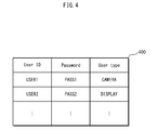
- the user managing unit 212 manages user information database 400 , a specific example of which is shown in FIG. 4 .
- the user information database 400 is composed of a set of user records of the users registered in the live video delivery system, each user record showing personal information of a user.
- Each user record is composed of fields for a user ID, a password, and a user type.
- the user ID field stores the user ID assigned to each user at the time of the user registration.
- the user ID is used for identifying the user.
- the password field stores a character string used for verification at the time of the logging in.
- the user type field stores a variable used for distinguishing between the recording user (“CAMERA” in FIG. 4 ) having the video recorder terminal 301 and the viewing user (“DISPLAY” in FIG. 4 ) having the viewer terminal 311 .
- the video recorder terminal managing unit 213 manages a video recorder terminal information database 500 shown in FIG. 5 .
- the video recorder terminal information database 500 shows information of the video recorder terminal 301 that has logged in the live video delivery system.
- the video recorder terminal information database 500 is composed of a set of video recorder terminal records, which is created when the corresponding video recorder terminal 301 logs in the system, and is deleted when the corresponding video recorder terminal 301 logs out of the system.
- Each video recorder terminal record is composed of fields for a video recorder terminal ID, a user ID, a location information, a location update time, and a broadcast status.
- the video recorder terminal ID field stores a video recorder terminal ID assigned to each video recorder terminal 301 at the time of the logging in.
- the video recorder terminal ID is used for identifying the video recorder terminal 301 . Note that the same video recorder terminal is assigned the same video recorder terminal ID at the logging in.
- the user ID field stores the user ID used when the video recorder terminal 301 logged in the system.
- the location information field stores the current latitude and longitude of the video recorder terminal 301 .
- the terminal location update time field stores the time of the last update of the location information field.
- the broadcast status field stores a status variable for managing the broadcast status of the video recorder terminal 301 .
- the broadcast status of the video recorder terminal is one of the following three statuses: “BROADCASTING” indicating that the video recorder terminal is now transmitting a live video to the delivery server 210 ; “PREPARING” indicating that the video recorder terminal has accepted the notified request and is now preparing for recording a live video at the desired recording location; and “WAITING” indicating that the video recorder terminal is not engaging in the delivery or in the preparation.
- the viewer terminal managing unit 214 manages a viewer terminal information database 600 shown in FIG. 6 .
- the viewer terminal information database 600 shows information of the viewer terminal 311 that has logged in the live video delivery system.
- the viewer terminal information database 600 is composed of a set of viewer terminal records, which is created when the corresponding viewer terminal 311 logs in the system, and is deleted when the corresponding viewer terminal 311 logs out of the system.
- Each viewer terminal record is composed of fields for a viewer terminal ID, a user ID, and a viewing status.
- the viewer terminal ID field stores a viewer terminal ID assigned to each viewer terminal 311 at the time of the logging in.
- the viewer terminal ID is used for identifying the viewer terminal 311 .
- the same viewer terminal is assigned the same viewer terminal ID at the logging in.
- the user ID field stores the user ID used when the viewer terminal 311 logged in the system.
- the viewing status field stores the video recorder terminal ID of the video recorder terminal 301 that is broadcasting the live video that the viewer terminal 311 is now viewing. Note that a null value is stored in this field when the viewer terminal 301 is not viewing the video.
- the delivery video managing unit 215 manages the live video received from the video recorder terminal 301 , in order to deliver the live video to the viewer terminal 311 .
- Live videos are managed in association with the video recorder terminal IDs of the video recorder terminals 301 that records the videos. Therefore, by specifying the video recorder terminal ID, the delivery server 210 can deliver the live video recorded by any of the video recorder terminals 301 to the viewer terminal 311 .
- the delivery request managing unit 216 manages a delivery request information database 700 shown in FIG. 7 .
- the delivery request information database 700 is composed of a set of delivery request records showing information of the delivery request acquired by the request acquiring unit 203 .
- Each delivery request record is composed of fields for a request number, a viewer terminal ID, and a desired recording location.
- the request number field stores the request number assigned at the acquisition of the delivery request.
- the viewer terminal ID field stores the viewer terminal ID of the viewer terminal 311 that is the originator of the delivery request.
- the desired recording location field stores the desired location (i.e. the latitude and longitude) specified in the delivery request.
- the delivery history managing unit 217 manages the history of video deliveries made in the past by the delivery server.
- FIG. 8 shows a specific example of the delivery history information database 800 managed by the delivery history managing unit 217 .
- Each delivery history record is composed of fields for a delivery number, a user ID, a video recorder terminal ID, a delivery commencement time, a delivery termination time, and a request number.
- the delivery number field stores a delivery number that is assigned at the time of the creation of the delivery history record.
- the user ID field stores the user ID of the video recorder terminal 301 that broadcasted a live video.
- the video recorder terminal ID field stores the video recorder terminal ID of the video recorder terminal 301 that broadcasted the live video.
- the delivery commencement time field stores the time when the video recorder terminal 301 started the transmission of the live video to the delivery server 210 .
- the delivery termination time field stores the time when the video recorder terminal 301 ended the transmission of the live video to the delivery server 210 .
- the request number field stores the request number of the delivery request when broadcasting of the live video was made in response to a delivery request, and stores a null value when broadcasting of the live video was made not in response to a delivery request, but was made according to the recording user's own free will.
- the notification history managing unit 206 manages the history of the notifications of the delivery requests in the past made by the delivery server as shown in the overview.
- FIG. 9 shows a specific example of the notification history information database 900 under the management of the notification history managing unit 206 .
- Each notification history record is composed of fields for a notification number, a user ID, a video recorder terminal ID, acceptance information, a location at the time of the request notification, a desired recording location, and a request notification time.
- the notification number field stores a notification number that is assigned at the time of the creation of the notification history record.
- the user ID field stores the user ID of the video recorder terminal 301 that received the notification.
- the video recorder terminal ID field stores the video recorder terminal ID of the video recorder terminal 301 that received the notification.
- the field for the location at the time of the notification stores the location information of the video recorder terminal 301 that received the notification, at the time the notification was provided.
- the desired recording location field stores the desired recording location specified in the notified delivery request.
- the acceptance information field stores acceptance information indicating the response from the video recorder terminal 301 corresponding to the notified delivery request.
- the request notification time field stores information indicating the date and time of the notification of the delivery request.
- the delivery server 210 thus records, as the history, two kinds of location information, namely the location at the time of the notification and the desired recording location, and the acceptance information.
- the delivery server 210 can thereby determine the degree of the tendency to accept the request for each video recorder terminal 301 in association with the distance from the location at the time of the notification to the desired recording location.
- the video recorder terminal searching unit 217 searches for the video recorder terminal 301 in response to a search request from the viewer terminal 311 . Specifically, the video recorder terminal searching unit 218 acquires search conditions from the viewer terminal 311 , and acquires the video recorder terminal record that satisfy the acquired search conditions and has the broadcast status “BROADCASTING” or “PREPARING”.
- the search conditions specify a geographical range. Specifically, the search conditions specify the latitude and longitude of the central point, and the radius.
- the video recorder terminal 301 that satisfy the search conditions is the video recorder terminal 301 that exists within the geographical range specified by the search conditions.
- the video recorder terminal searching unit 218 determines whether the search conditions are satisfied or not by calculating the distance between the location indicated by each video recorder terminal record in the video recorder terminal information database 500 and the location of the central point indicated by the search conditions, and comparing the distance with the radius indicated by the search conditions.
- the search conditions are specified from a user interface of the viewer terminal 311 .
- Examples of the user interface of the viewer terminal 311 for specifying the search conditions include: an interface for receiving numerical values representing the latitude, the longitude and the radius; and an interface showing a map on the screen of the viewer terminal 311 as shown in FIG. 10 in response to a user instruction, and receiving a specification of the location (i.e. latitude and longitude) and the radius within the range of the map.
- the viewer terminal 311 displays such a map, it is preferable that landmark icons showing stations, railroad maps, famous buildings are overlaid on the map to enable the viewing user to more intuitively specify the search conditions.
- the viewing user may be allowed to input the address or the information that specifies the location as instructed by the user interface of the viewer terminal 311 , and the viewer terminal 311 may convert the information into the latitude and the longitude.
- the information that specifies the location is the information that uniquely specifies the latitude and the longitude of the recording location, such as “the entrance gate of the amusement park A” and “the plaza in front of the station B”.
- the delivery server 210 may include a converter for converting the address or the information specifying the location to the location (i.e. latitude and longitude), and the delivery server 210 may perform the conversion.
- the terminal list notifying unit 219 has the functions of: creating a video recorder terminal list from the results of the search performed by the searching unit 218 , and providing the viewer terminal 311 with the video recorder terminal list thus created; and creating a video recorder terminal list showing the video recorder terminals that received the delivery request, and providing the viewer terminal 311 that is the request originator with the video recorder terminal list thus created.
- the video recorder terminal list contains the video recorder terminal ID, the location information and the broadcast status for each video recorder terminal in the list.
- the video recorder terminal list is transmitted to the viewer terminal 311 .
- the video recorder terminal list transmitted to the viewer terminal 311 is provided to the viewing user via the user interface of the viewer terminal 311 .
- Examples of the user interface of the viewer terminal include: a simple presentation of the list as shown in FIG. 11A ; and the presentation of information overlaid on the map as shown in FIG. 11B .
- the terminal list notifying unit 219 may transmit snapshot images of the live video that is being broadcasted by each video recorder terminal 301 or a compressed version of the live video with a greatly reduced data amount due to a reduced display resolution (i.e. the number of pixels) to the viewer terminal 311 in addition to the video recorder terminal list. If this is the case, the viewer terminal 311 can display them together with the video recorder terminal list, and the viewing user can acquire more information from the video recorder terminal list.
- the video receiving/transmitting unit 220 has the functions of: receiving the live video from the video recorder terminals 301 ; and delivering the live video to the viewer terminals 311 .
- the request acquiring unit 201 acquires the delivery request including the desired recording location specified by the viewing user from the viewer terminal 311 .
- the delivery request managing unit 216 creates a delivery request record based on the delivery request acquired by the request acquiring unit 201 , and adds the record to the delivery request information database 700 .
- the desired recording location is specified by the viewing user from the user interface of the viewer terminal 311 .
- examples of the user interface of the viewer terminal 311 for specifying the desired recording location include: an interface for receiving numerical values representing the latitude and the longitude; an interface showing a map on the screen of the viewer terminal 311 in response to a user instruction, and receiving a specification of the location (i.e. latitude and longitude) within the range of the map; and an interface for converting an input address or the like to the location.
- the terminal location acquiring unit 202 acquires the current location information of the video recorder terminal 301 .
- the terminal location acquiring unit 202 periodically acquires the current location information of the video recorder terminal 301 .
- the video recorder terminal managing unit 213 updates the video recorder terminal information database 500 according to the location information acquired by the terminal location acquiring unit 202 .
- each video recorder terminal 301 holds information of its own location obtained by positioning using GPS or information from a base station for portable telephones.
- the request notification terminal selecting unit 203 selects video recorder terminals 301 to be provided with a notification of the delivery request. The processing for selecting the delivery request will be described later in detail.
- the request notifying unit 204 provides a notification to the video recorder terminals 301 selected by the request notification terminal selecting unit 203 .
- the delivery request received from the viewer terminal 311 and the delivery request to be transmitted to the video recorder terminals 301 necessarily coincide in terms of the desired recording location, but except for the desired recording location, some of the information contained in one of the delivery request may be not contained in the other.
- the acceptance information acquiring unit 205 acquires the acceptance information related to the notified delivery request.
- the notification history managing unit 206 updates the notification history information database 900 according to the acceptance information acquired by the acceptance information acquiring unit 205 .
- the control unit 220 controls each of the functional elements in order to achieve the functions described above.
- the live video delivery system pertaining to the present embodiment has two approaches for enabling the delivery server 210 to deliver the live video recorded by the video recorder terminal 301 to the viewer terminal 311 .
- One is to deliver, to the viewer terminal 311 , the live video selected by the viewer terminal 311 from among the live videos already being broadcasted, and the other is to deliver, to the viewer terminal 311 , the live video recorded by the video recorder terminal 301 in response to a request from the viewer terminal 311 .
- FIG. 12 shows the operations of the viewer terminal 311 , the delivery server 210 and the video recorder terminal 301 performed when the delivery server 210 delivers the live video, selected by the viewer terminal 311 from among live videos already being broadcasted, to the viewer terminal 311 .
- the video recorder terminal 301 starts recording at the current location of the video recorder terminal 301 in response to an instruction of the recording user. Simultaneously with starting the recording, the video recorder terminal 301 provides the delivery server with a notification of starting the transmission of the live video, and starts transmitting the live video to the delivery server 210 (S 1201 ).
- the video recorder terminal managing unit 213 of the delivery server 210 Upon receipt of the notification of the commencement of the video transmission from the video recorder terminal 301 , the video recorder terminal managing unit 213 of the delivery server 210 updates the video recorder terminal information database 500 (S 1202 ). Specifically, the video recorder terminal managing unit 213 updates the broadcast status field of the corresponding video recorder terminal broadcast record from “WAITING” to “BROADCASTING”.
- the delivery history managing unit 217 of the delivery server 210 Upon receipt of the notification of the commencement of the video transmission from the video recorder terminal 301 , the delivery history managing unit 217 of the delivery server 210 creates a delivery history record according to the information of the live video to be newly broadcasted, and adds the record to the delivery history information database 800 (S 1203 ).
- the fields for the delivery number, the user ID, the video recorder terminal ID and the delivery commencement time are respectively filled with the delivery number that is automatically assigned, the user ID of the video recorder terminal that transmitted the live video, the video recorder terminal ID, and the current time.
- the fields for the delivery termination time and the request number are filled with a null value.
- the video receiving/transmitting unit 220 of the delivery server 210 receives the live video in a stream format transmitted by the video recorder terminal 301 , and the delivery video managing unit 215 manages the live video in association with the video recorder terminal ID.
- the viewer terminal 311 Independently from the operations of the video recorder terminal 301 , the viewer terminal 311 transmits search conditions to the delivery server 210 in response to an instruction from the viewing user (S 1204 ).
- the video recorder terminal searching unit 218 of the delivery server 210 searches for the video recorder terminals 301 that satisfy the search conditions and that are broadcasting or preparing for broadcasting the live video (S 1205 ).
- the terminal list notifying unit 219 Upon completion of the search for the video recorder terminals 301 , the terminal list notifying unit 219 creates a video recorder terminal list according to the search results, and transmits the video recorder terminal list to the viewer terminal 311 (S 1206 ).
- the viewer terminal 311 selects one of the video recorder terminals 301 from the received video recorder terminal list, and transmits, to the delivery server 210 , a request for delivery of the live video that is being recorded by the selected video recorder terminal 301 (S 1207 ).
- the video receiving/transmitting unit 220 of the delivery server 210 Upon receipt of the delivery request from the viewer terminal 311 , the video receiving/transmitting unit 220 of the delivery server 210 transmits, to the viewer terminal 311 , the live video specified from among the live videos that are under the management of the delivery video managing unit 215 (S 1208 ). Then, the viewer terminal 311 starts playing the live video that is being delivered.
- the viewer terminal managing unit 214 of the delivery server 210 Upon receipt of the delivery request from the viewer terminal 311 , the viewer terminal managing unit 214 of the delivery server 210 updates the viewing status field of the corresponding viewer terminal record in the viewer terminal information database 600 according to the received delivery request (S 1209 ).
- the delivery server 210 delivers, to the viewer terminal 311 , the live video already being broadcasted.
- the following describes the operations of the viewer terminal 311 , the delivery server 210 and the video recorder terminal 301 performed when the delivery server 210 delivers, to the viewer terminal 311 , the live video recorded by the video recorder terminal 301 in response to the request from the viewer terminal 311 .
- the viewer terminal 311 transmits the delivery request to the delivery server 210 according to an instruction from the viewing user (S 1301 ).
- the delivery request managing unit 216 of the delivery server 210 Upon receipt of the delivery request from the viewer terminal 311 , the delivery request managing unit 216 of the delivery server 210 creates a delivery request record according to the delivery request, and adds the record to the delivery request information database 700 (S 1302 ).
- the request notification terminal selecting unit 203 of the delivery server 210 Upon the completion of the update of the delivery request information database 700 , the request notification terminal selecting unit 203 of the delivery server 210 performs request notification terminal selection, which will be described later, so as to select the video recorder terminal 301 that is likely to accept the delivery request from the viewing user (S 1303 ).
- the number of the video recorder terminals selected at a time during the request notification terminal selection by the request notification terminal selecting unit 203 is 0 or more.
- the delivery server 210 notifies the viewer terminal 311 of that no terminal has accepted the delivery request, and terminates the processing.
- the request notifying unit 203 of the delivery server 210 provides the selected video recorder terminal 301 with a notification of the delivery request (S 1304 ).
- the notification history managing unit 206 creates a notification history record according to the information of the delivery request and the video recorder terminal 301 receiving the notification, and adds the record to the notification history information database 900 (S 1305 ).
- the video recorder terminal 301 that has been provided with the notification of the delivery request transmits, to the delivery server 210 , acceptance information indicating whether or not to accept the delivery request (S 1306 ).
- the notification history managing unit 206 of the delivery server 210 Upon receipt of the acceptance information from the video recorder terminal 301 , the notification history managing unit 206 of the delivery server 210 updates the corresponding notification history record in the notification history information database 900 according to the acceptance information (S 1307 ).
- the video recorder terminals that have not responded to the request within a predetermined period are determined as terminals that have rejected the request.
- the request notification terminal selecting unit 203 returns to Step S 1303 and performs the selection from the video recorder terminals again, excluding the video recorder terminals to which the notification of the delivery request have already been transmitted.
- the video recorder terminal managing unit 213 of the delivery server 210 Upon receiving the acceptance information indicating the acceptance of the request from the video recorder terminal 301 , the video recorder terminal managing unit 213 of the delivery server 210 updates the broadcast status field of the corresponding video recorder terminal record in the video recorder terminal information database 500 to “PREPARING” (S 1310 ).
- the terminal list notifying unit 219 of the delivery server 210 Upon completion of the update of the video recorder terminal information database 500 , the terminal list notifying unit 219 of the delivery server 210 creates a terminal list showing the video recorder terminals 301 that have accepted the delivery request, and provides the viewer terminal 311 with a notification showing the video recorder terminals 301 that have accepted the delivery request (S 1311 ). By receiving the notification, the viewer terminal 311 is informed of that some of the video recorder terminals 301 have accepted the request.
- the video recorder terminal 301 that has accepted the delivery request travels to the desired recording location specified in the delivery request, and starts recording. Simultaneously with starting the recording, the video recorder terminal 301 provides the delivery server with a notification of the commencement of the transmission of the live video, and starts transmitting the live video to the delivery server 210 (S 1312 ).
- the video recorder terminal managing unit 213 of the delivery server 210 Upon receipt of the notification indicating the commencement of the video transmission, the video recorder terminal managing unit 213 of the delivery server 210 updates the broadcast status field of the corresponding video recorder terminal record in the video recorder terminal information database 500 from “PREPARING” to “BROADCASTING” (S 1313 ).
- the delivery history managing unit 217 of the delivery server 210 Upon receipt of the notification of the commencement of the video transmission from the video recorder terminal 301 , the delivery history managing unit 217 of the delivery server 210 creates a delivery history record according to the information of the live video to be newly broadcasted, and adds the record to the delivery history information database 800 (S 1314 ).
- the fields for the delivery number, the user ID, the video recorder terminal ID, the delivery commencement time, and the request number are respectively filled with the delivery number that is automatically assigned, the user ID of the video recorder terminal that transmitted the live video, the video recorder terminal ID, the current time, and the corresponding request number.
- the field for the delivery termination time is filled with a null value.
- the video receiving/transmitting unit 220 of the delivery server 210 receives the live video in a stream format transmitted by the video recorder terminal 301 , and the delivery video managing unit 215 manages the live video in association with the video recorder terminal ID.
- the terminal list notifying unit 219 of the delivery server 210 Upon completion of the update of the video recorder terminal information database 500 , the terminal list notifying unit 219 of the delivery server 210 creates a terminal list showing the video recorder terminals 301 that have accepted the delivery request, and provides the viewer terminal 311 with a notification (S 1315 ). By receiving the notification, the viewer terminal 311 is informed of that the video recorder terminals 301 that have accepted the request have started broadcasting the live video.
- the viewer terminal 311 selects the video recorder terminal 301 from the received video recorder terminal list, and transmits, to the delivery server 210 , a request for delivery of the live video that is being recorded by the selected video recorder terminal 301 (S 1316 ).
- the video receiving/transmitting unit 220 of the delivery server 210 Upon receipt of the delivery request from the viewer terminal 311 , the video receiving/transmitting unit 220 of the delivery server 210 transmits, to the viewer terminal 311 , the live video specified from among the live videos under the management of the delivery video managing unit 215 (S 1317 ).
- the viewer terminal managing unit 214 of the delivery server 210 Upon receiving the delivery request from the viewer terminal 311 , the viewer terminal managing unit 214 of the delivery server 210 updates the viewing status field of the corresponding viewer terminal record in the viewer terminal information database 600 according to the received delivery request (S 1318 ).
- the viewer terminal 311 starts playing the delivered live video.
- the delivery server 210 delivers, to the viewer terminal 311 , the live video being recorded by the video recorder terminal 301 in response to the request from the viewer terminal 311 .
- FIG. 15 shows the operations of the viewer terminal 311 and the delivery server 210 performed when the delivery server 210 terminates the delivery of the live video in response to an operation of the viewer terminal 311 .
- the viewer terminal 311 stops playing back the live video, and transmits, to the delivery server 210 , a delivery termination request for termination of the delivery of the live video (S 1501 ).
- the viewer terminal managing unit 214 of the delivery server 210 Upon receiving the delivery termination request from the viewer terminal 311 , the viewer terminal managing unit 214 of the delivery server 210 updates the viewing status field of the corresponding viewer terminal record in the viewer terminal information database 600 according to the delivery termination request (S 1502 ).
- the video receiving/transmitting unit 220 of the delivery server 210 Upon receipt of the delivery termination request from the viewer terminal 311 , the video receiving/transmitting unit 220 of the delivery server 210 terminates the delivery of the live video to the viewer terminal 311 according to the delivery termination request (S 1503 ).
- the delivery server 210 determines whether or not the delivery of the live video which has been terminated was requested for by the viewer terminal that has made the delivery termination request, referring to the delivery history information database 800 that is under the management of the delivery history managing unit 217 and the delivery request information database 700 that is under the management of the delivery request managing unit 216 .
- the delivery server 210 provides the video recorder terminal 301 with a notification indicating that the viewer terminal 311 as the requester of the live video has terminated the viewing of the live video, i.e. the request has been completed (S 1504 ).
- the delivery server 210 terminates the delivery of the live video to the viewer terminal 311 .
- FIG. 16 shows the operations of the viewer terminal, the delivery server 210 and the video recorder terminal performed when the delivery server 210 terminates the delivery of the live video in response to an operation of the video recorder terminal 301 .
- the video recorder terminal 301 provides the delivery server 210 with a notification of the termination of the transmission of the live video, and then terminates the transmission of the live video to the delivery server 210 (S 1601 ).
- the video recorder terminal managing unit 213 of the delivery server 210 Upon receipt of the notification of the transmission of the live video from the video recorder terminal 301 , the video recorder terminal managing unit 213 of the delivery server 210 updates the broadcast status field of the corresponding video recorder terminal record in the video recorder terminal information database 500 from “BROADCASTING” to “WAITING” (S 1602 ).
- the viewer terminal managing unit 214 of the delivery server 210 Upon receipt of the notification of the transmission of the live video from the video recorder terminal 301 , the viewer terminal managing unit 214 of the delivery server 210 searches the viewer terminal information database 600 for the viewer terminal record of the viewer terminal that is viewing the live video from the corresponding video recorder terminal, and updates the viewing status field (S 1603 ).
- the viewer terminal managing unit 214 of the delivery server 210 provides the viewer terminal 311 that has updated the viewing status with a notification of the termination of the delivery of the live video, and then terminates the delivery to the viewer terminal 311 (S 1604 ).
- the delivery history managing unit 217 of the delivery server 210 fills the delivery termination time field of the corresponding record in the delivery history information database 800 with the current time (S 1605 ).
- the delivery server 210 determines whether or not the delivery of the live video which has been terminated was requested for by the viewer terminal 311 , referring to the request number field in the delivery history information database 800 .
- the delivery server 210 provides the viewer terminal 311 that made the corresponding request with a notification of the termination of the delivery of the live video recorded by the video recorder terminal 301 that accepted the delivery request (S 1606 ).
- the delivery server 210 terminates the delivery of the live video to the viewer terminal 311 .
- FIG. 17 is a flowchart of the processing performed by the request notification terminal selecting unit 203 of the delivery server 210 for selecting the video recorder terminal to be provided with the delivery request.
- the request notification terminal selecting unit 203 selects one of the video recorder terminal records in the video recorder terminal information database 500 that is under the management of the video recorder terminal managing unit 213 (S 1701 ).
- the request notification terminal selecting unit 203 performs the broadcast expectation value calculation, which will be described later, to calculate the broadcast expectation value of the selected video recorder terminal 301 (S 1702 ).
- the request notification terminal selecting unit 203 determines whether or not all the video recorder terminal records in the video recorder terminal information database 500 have been selected in Step S 1701 (S 1703 ). When all the video recorder terminal records have been selected (S 1703 : Yes), the request notification terminal selecting unit 203 moves to Step S 1704 . If any of the video recorder terminal records remain unselected (S 1703 : No), the request notification terminal selecting unit 203 returns to Step S 1701 .
- the request notification terminal selecting unit 203 selects, from among the video recorder terminals with the broadcast expectation value greater than a predetermined value (e.g. 0.2), a predetermined number (e.g. 10) of the video recorder terminals at a time as the video recorder terminals to be notified of the delivery request, in the order of the decreasing broadcast expectation values (S 1704 ).
- a predetermined value e.g. 0.2
- a predetermined number e.g. 10
- FIG. 18 is a flowchart showing the details of the processing performed in Step S 1702 for calculating the broadcast expectation value of the video recorder terminal 301 .
- the video recorder terminal whose broadcast expectation value is to be calculated is referred to as “the target terminal”, and the delivery request to be notified of is referred to as “the target request”.
- the request notification terminal selecting unit 203 calculates a current distance showing the distance between the current location of the target terminal and the desired recording location indicated by the target request (S 1801 ).
- the current location of the target terminal is acquired from the location information field of the video recorder terminal record of the target terminal in the video recorder terminal information database 500 that is under the management of the video recorder terminal managing unit 213 .
- the desired recording location indicated by the target request is acquired from the desired recording location field of the delivery request record of the target request in the delivery request information database 700 that is under the management of the delivery request managing unit 216 .
- the request notification terminal selecting unit 203 creates an actual acceptance database 1900 which shows the history of the acceptance of the requests notified to the target terminals in the past (S 1802 ).
- the actual acceptance database 1900 shows the relationship between the distance from the target terminal to the desired recording location at the time the notification was provided and the acceptance information of the target terminal corresponding to the notification.
- FIG. 19 shows the processing performed by the request notification terminal selecting unit 203 for creating the actual acceptance database 1900 when the video recorder terminal ID of the target terminal is “CAM10”.
- the request notification terminal selecting unit 203 selects, from the notification history information database 900 that is under the management of the notification history managing unit 206 , one of the notification history records whose video recorder terminal ID field stores the video recorder terminal ID of the target terminal.
- the drawing shows that the notification history record 1901 whose notification number is “NOTICE3” is selected.
- the request notification terminal selecting unit 203 calculates the distance at the notification, which indicates the distance between the two locations, namely the location indicated by the field of the location at the time of the notification and the location indicated by the desired recording location field, both contained in the selected notification history record.
- the drawing shows that the distance “D1” at the time of the notification is calculated from the two locations indicated by the location information “X14, Y14” and “X15, Y15”.
- the request notification terminal selecting unit 203 creates an actual acceptance record containing, as the values thereof, the distance at the time of the notification thus calculated and the acceptance information stored in the acceptance information field of the selected notification history record.
- the drawing shows that the actual acceptance record 1902 is created from the distance “D1” at the time of the notification and the acceptance information “FALSE” of the notification history record 1901 .
- the request notification terminal selecting unit 203 creates actual acceptance records from all the notification history records of the target terminal, and thereby creates the actual acceptance database 1900 .
- the request notification terminal selecting unit 203 calculates a distance tendency value indicating the request acceptance rates of the target terminal in the case the distance at the time of the notification is similar to the current distance (S 1803 ).
- the distance is classified into a plurality of categories (0 m to 10 m, 10 m to 20 m, 20 m to 50 m, . . . , 5 km to 10 km, 10 km or longer).
- the request notification terminal selecting unit 203 specifies one of the categories as the current distance.
- the request notification terminal selecting unit 203 extracts, from the actual acceptance database 1900 , the records whose distance at the time of the notification belongs to the same category as the current distance.
- the request notification terminal selecting unit 203 determines, as the distance tendency value, the ratio of the number of the records whose acceptance information is “TRUE” to the total number of the extracted records.
- the distance tendency value is 0.3 when the following conditions are satisfied: the current distance of the target terminal is 15 m; the number of actual acceptance records whose distance at the time of the notification falls within the range from 10 m to 20 m; and the acceptance information of three records out of the ten records indicates “TRUE”. It can be considered that the distance tendency value decreases as the current distance increases as shown in FIG. 20 .
- the request notification terminal selecting unit 203 sets the distance tendency value thus calculated to the broadcast expectation value of the target terminal, and terminates the processing (S 1804 ).
- a null value is set to the broadcast expectation value in Step S 1803 when the number of the actual acceptance records belonging to the same category of the current distance is no greater than a predetermined number (e.g. 10).
- the video recorder terminal whose broadcast expectation value is null is always provided with a notification of the delivery request in Step S 1804 .
- the video recorder terminal whose notification history is not sufficient is always provided with a notification of the delivery request so as to accumulate the notification history.
- the location at the time of the notification, the desired recording location, and the acceptance information are recorded as the history of the notifications of the requests in the past.
- This structure allows for calculation of the broadcast expectation value of each video recorder terminal.
- the live video delivery system is therefore capable of selecting only video recorder terminals that are likely to accept the request and giving the notification to them.
- the live video delivery system pertaining to the present embodiment increases the probability of the delivery of the live video recorded at the location desired by the viewing user, and decreases the probability of unnecessary notification of the request to the recording users that are unwilling to accept the request. This is highly advantageous.
- a live video delivery system is described above.
- the present invention is not limited to the live video delivery system described above, and may be modified as follows. The following describes modifications of the present invention within the scope of the concept of the present invention.
- the live video delivery system described above as an embodiment calculates the distance tendency value from the notification history in the past, based on the relationship between the location of the target terminal at the time of the notification and the desired recording location. That is, the live video delivery system described above as an embodiment uses only the information about the distance to the desired recording location in order to determine the degree of the tendency to accept the request (i.e. the willingness to broadcast the video).
- the degree of the tendency of the recording user to accept the request varies depending on time attributes such as the day of the week and the time of day. For example, some recording users may not be able to accept a request on week days because of work, but may be able to accept a request on weekends. Some recording users may not be able to accept a request in the morning and the night because of housework, but may be able to accept a request during the day.
- the live video delivery system pertaining to the present invention may be modified to use notification time information managed as history information and to calculate the broadcast expectation value taking the notification time information into consideration.
- FIG. 21 is a flowchart showing operations for calculating the broadcast expectation value of the target terminal taking the time information into consideration. The same steps as contained in FIG. 18 are given the same reference numbers and their explanations will be omitted.
- the request notification terminal selecting unit 203 creates an actual acceptance database 2200 which shows the history of the acceptance of the requests notified to the target terminal in the past (S 2101 ).
- the actual acceptance database 2200 shows the relationship between the distance from the target terminal to the desired recording location at the time the notification was provided, the time at which the notification was made, and the acceptance information of the target terminal corresponding to the notification.
- the request notification terminal selecting unit 203 selects one of the notification history records of the target terminal from the notification history information database 900 , and calculates the distance at the time of the notification.
- the request notification terminal selecting unit 203 creates an actual acceptance record by combining the distance at the time of the notification thus calculated, the notification time contained in the selected notification history record, and the acceptance information contained in the selected notification history record.
- the request notification terminal selecting unit 203 creates actual acceptance records from all the notification history records of the target terminal, and thereby creates the actual acceptance database 2200 .
- FIG. 22 shows a specific example of the actual acceptance database 2200 created by the request notification terminal selecting unit 203 .
- Step S 1803 is the step of calculating the distance tendency value.
- the request notification terminal selecting unit 203 calculates a time tendency value indicating the acceptance rate of the request having the same time attribute as the current time (S 2102 ).
- the time is classified into a plurality of categories (e.g. Sunday, Monday, . . . , Friday, Saturday).
- the request notification terminal selecting unit 203 specifies the category to which the current time belongs.
- the request notification terminal selecting unit 203 extracts, from the actual acceptance database 2100 , the records whose notification time belongs to the same category as the current time.
- the request notification terminal selecting unit 203 determines, as the time tendency value, the ratio of the number of the records whose acceptance information is “TRUE” to the total number of the extracted records.
- the time may be classified into morning, midday, evening and night, or be classified in units of hours or minutes. Furthermore, the time may be classified according to the combinations of the above, such as “Sunday, morning”, “Sunday, midday”, etc.
- the request notification terminal selecting unit 203 calculates the broadcast expectation value of the target terminal by using the distance tendency value and the time tendency value thus calculated (S 2103 ).
- the request notification terminal selecting unit 203 uses the geometric mean of the distance tendency value and the time tendency value as the broadcast expectation value.
- the request notification terminal selecting unit 203 may use the arithmetic mean, the weighted mean, the product or the sum of the distance tendency value and the time tendency value.
- the distance tendency value or the time tendency value whichever is larger may be used as the broadcast expectation value.
- the degree of the tendency of the recording user to accept the request possibly changes depending on the current location of the recording user. For example, a recording user possibly cannot accept a request when he/she is at work or school.
- the live video delivery system pertaining to the present invention may be modified to use notification time information managed as history information and to calculate the broadcast expectation value taking into consideration the variations in the degree of the tendency to accept the request depending on the location.
- FIG. 23 is a flowchart showing operations for calculating the broadcast expectation value of the target terminal taking the location information into consideration. The same steps as contained in FIG. 18 are given the same reference numbers and their explanations will be omitted.
- the request notification terminal selecting unit 203 creates an actual acceptance database 2400 which shows the history of the acceptance of the requests notified to the target terminals in the past (S 2301 ).
- the actual acceptance database 2400 shows the relationship between the distance from the target terminal to the desired recording location at the time the notification was provided, the location of the target device at the time the notification was made, and the acceptance information of the target terminal corresponding to the notification.
- the request notification terminal selecting unit 203 selects one of the notification history records of the target terminal from the notification history information database 900 , and calculates the distance at the time of the notification.
- the request notification terminal selecting unit 203 creates an actual acceptance record by combining the location at the time of the notification thus calculated and the acceptance information contained in the selected notification history record.
- the request notification terminal selecting unit 203 creates actual acceptance records from all the notification history records of the target terminal, and thereby creates the actual acceptance database 2400 .
- FIG. 24 shows a specific example of the actual acceptance database 2400 created by the request notification terminal selecting unit 203 .
- Step S 1803 is the step of calculating the distance tendency value.
- the request notification terminal selecting unit 203 calculates a location tendency value indicating the request acceptance rate when the target terminal is provided with the notification within a predetermined range of the current location (e.g. within a 20 m radius) (S 2302 ).
- the request notification terminal selecting unit 203 first calculates the distance between the location at the time of the notification and the current location for each actual acceptance record in the actual acceptance database 2400 , and extracts the records whose location at the time of the notification is within a predetermined range of the current location. Then, the request notification terminal selecting unit 203 determines, as the location tendency value, the ratio of the number of the records whose acceptance information is “TRUE” to the total number of the extracted records.
- the request notification terminal selecting unit 203 calculates the broadcast expectation value of the target terminal by using the distance tendency value and the location tendency value thus calculated (S 2303 ).
- the request notification terminal selecting unit 203 uses the geometric mean of the distance tendency value and the location tendency value as the broadcast expectation value.
- the request notification terminal selecting unit 203 may use the arithmetic mean, the weighted mean, the product or the sum of the distance tendency value and the location tendency value.
- the distance tendency value or the location tendency value whichever is larger may be used as the broadcast expectation value.
- a particular location for the recording user may be registered with the delivery server 210 , and the delivery server 210 may not provide a notification of a request to the video recorder terminal 301 whose current location is within a certain range of the registered location.
- the degree of the tendency of the recording user to accept the request possibly changes according to the category of the desired recording location included in the delivery request, that is the category of the subject of the recording. In other words, when the recording user is interested in the subject of the recording, the recording user might travel all the way to the desired recording location even if the recording user is away from the desired recording location. On the other hand, when the recording user is not interested in the subject of the recording, the recording user might not accept the request even if the recording user is close to the desired recording location.
- the live video delivery system pertaining to the present invention may be modified by adding a structure for managing a database associating the location information and the categories of the subject of the recording, so as to calculate the broadcast expectation value taking into consideration the variations in the degree of the tendency to accept the request depending on the category of the subject of the recording.
- FIG. 25 shows a functional structure of a delivery server 2500 taking into consideration the variations in the degree of the tendency to accept the request, depending on the category of the subject of the recording.
- the delivery server 2500 is structured by adding a location category information managing unit 2501 to the delivery server 210 shown in FIG. 3 .
- the location category information managing unit 2501 manages a location category information database 2600 shown in FIG. 26 .
- the location category information database 2600 is a database used for acquiring the category information based on the location information. Each record is composed of fields for location information and category information.
- the location information field stores location information composed of the latitude and the longitude.
- the category information field stores category information representing what is at the location indicated by the location information, such as an object and scenery. For example, in the drawing, the category information of the location (X10, Y10) represents “Factory”, and the category information of the location (X11, Y11) represents “Traffic”.
- FIG. 27 is a flowchart showing operations performed by the request notification terminal selecting unit 203 of the delivery server 2500 , for calculating the broadcast expectation value of the target terminal taking the subject of the recording into consideration.
- the same steps as contained in FIG. 18 are given the same reference numbers and their explanations will be omitted.
- the request notification terminal selecting unit 203 acquires the category information of the current request (current category information) by using the delivery request information database 700 that is under the management of the delivery request managing unit 216 and the location category information database 2500 that is under the management of the location category information managing unit 2501 (S 2701 ). Specifically, the request notification terminal selecting unit 203 acquires the desired recording location of the target request from the delivery request information database 700 , and the category information of the desired recording location of the target request from the location category information database 2600 .
- the request notification terminal selecting unit 203 creates an actual acceptance database 2800 which shows the history of the acceptance of the requests notified to the target terminals in the past (S 2702 ).
- the actual acceptance database 2800 shows the relationship between the distance from the target terminal to the desired recording location at the time the notification was provided, the category information of the notified request (notification category information), and the acceptance information of the target terminal corresponding to the notification.
- FIG. 28 shows operations performed by the request notification terminal selecting unit 203 to create the actual acceptance database 2800 .
- the request notification terminal selecting unit 203 selects one of the notification history records (i.e. the notification history record 2801 ) of the target terminal from the notification history information database 900 , and calculates the distance at the time of the notification.
- the request notification terminal selecting unit 203 acquires the category information (notification category information) from the location category information database 2600 by using the desired recording location of the selected notification history record.
- the request notification terminal selecting unit 203 creates an actual acceptance record 2802 by combining the distance at the time of the notification thus calculated, the notification category information thus acquired, and the acceptance information contained in the selected notification history record.
- the request notification terminal selecting unit 203 creates actual acceptance records from all the notification history records of the target terminal, and thereby creates the actual acceptance database 2800 .
- Step S 1803 is the step of calculating the distance tendency value.
- the request notification terminal selecting unit 203 calculates a category tendency value indicating the acceptance rate of the request having the same notification category information as the current category information (S 2703 ).
- the request notification terminal selecting unit 203 extracts, from the actual acceptance database 2800 , the actual acceptance records whose category information is the same as the current category information. Then, the request notification terminal selecting unit 203 determines, as the category tendency value, the ratio of the number of the records whose acceptance information is “TRUE” to the total number of the extracted records.
- the request notification terminal selecting unit 203 calculates the broadcast expectation value of the target terminal by using the distance tendency value and the category tendency value thus calculated (S 2704 ).
- the request notification terminal selecting unit 203 uses the geometric mean of the distance tendency value and the category tendency value as the broadcast expectation value.
- the request notification terminal selecting unit 203 may use the arithmetic mean, the weighted mean, the product or the sum of the distance tendency value and the category tendency value.
- the distance tendency value or the category tendency value whichever is larger may be used as the broadcast expectation value.
- the live video delivery system described above as an embodiment relies only on the degree of the tendency to accept the request (i.e. the willingness to broadcast the video) to select the video recorder terminals to be notified of the delivery request.
- the live video delivery system pertaining to the present invention may be modified to calculate the broadcast expectation value taking the traveling distance of the video recorder terminal into consideration.
- FIG. 29 is a flowchart showing operations for calculating the broadcast expectation value of the target terminal taking the traveling distance into consideration. The same steps as contained in FIG. 18 are given the same reference numbers and their explanations will be omitted.
- Step S 1803 the request notification terminal selecting unit 203 determines the degree of weight according to the current distance calculated in Step S 1801 such that the weight is set lower for a longer current distance (S 2901 ).
- the request notification terminal selecting unit 203 calculates, as the broadcast expectation value, the product of the distance tendency value calculated in Step S 1803 and the weight calculated in Step S 2901 (S 2902 ).
- the broadcast expectation value may be obtained by subtracting a predetermined value (e.g. 0.1) from the distance tendency value when the current distance of the video recorder terminal is no less than a predetermined distance (e.g. 500 m).
- a predetermined distance e.g. 500 m.
- the distance tendency value may be used without change as the broadcast expectation value.
- the live video delivery system described above as an embodiment creates the actual acceptance database from the notification history records having the same video recorder terminal ID as the target terminal.
- the method of creating the actual acceptance database is not limited in this way.
- the user ID of the target terminal may be obtained from the video recorder terminal information database 500 that is under the management of the video recorder terminal managing unit 213 , and the actual acceptance database may be created from the notification history records having the same user ID as the target terminal.
- This structure allows for calculation of the broadcast expectation value taking into consideration the degree of the tendency of each recording user to accept the request, even when the recording user uses another video recorder terminal, when the recording user uses a plurality of video recorder terminals, and when a plurality of recording users share a video recorder terminal.
- the distance is classified into a plurality of categories (0 m to 10 m, 10 m to 20 m, 20 m to 50 m, . . . , 5 km to 10 km, 10 km or longer), and it is considered that distances belonging to the same category are substantially equal.
- classification is not essential.
- the distance may be classified into “very short distance (0 m to 20 m)”, “short distance (20 m to 100 m)”, “middle distance (100 m to 1 km)” and “long distance (1 km or longer)”.
- two distances may be determined as substantially equal when the absolute value of the difference between the two distances is smaller than a predetermined value (e.g. 20 m), or when the ratio of one distance to the other falls within a predetermined range (e.g. from 0.9 to 1.1).
- the content to be created and delivered according to a request is video data.
- the present invention is not limited in such a way.
- the present invention may be embodied as an apparatus for mediating requests for creation of digital content such as audio data and text data, instead of video data, that is valuable when created at the location of the accepter terminal.
- the function of acquiring the delivery request from the viewer terminal 311 and giving the video recorder terminal 301 the notification of the acquired request, and the function of receiving the live video from the video recorder terminal 301 and delivering the received live video to the viewer terminal 311 may be realized by using separate servers.
- the video recorder terminal list displayed by the viewer terminal 311 may be dynamically updated.
- the information about the update may be transmitted to the viewer terminal 311 , and the video recorder terminal list being displayed by the viewer terminal 311 may be updated accordingly.
- the delivery server 210 may further include a component for transmit update information to the viewer terminal 311 when the location information field, the broadcast status field, or the like of the record of the video recorder terminal information database 500 corresponding to the video recorder terminal 301 shown in the list, or when one or more video recorder terminal records additionally satisfy, for example, the condition transmitted by the viewer terminal 311 or the condition that the location of the video recorder terminal 301 is within a predetermined range (e.g. within 100 m range) of the desired recording location specified in the delivery request.
- a predetermined range e.g. within 100 m range
- This structure allows the viewing user to be timely informed of the increase or decrease of the number of the video recorder terminals that have the possibility to become the video recorder terminal 301 or the change in the locations of such video recorder terminals even while the viewing user is in the process of selecting the video recorder terminal 301 .
- the delivery server 210 acquires the acceptance information from the video recorder terminal 301 in an explicit manner (S 1306 ).
- the present invention is not limited in this way.
- the delivery server 210 may regard the notification of the commencement of the video transmission from the video recorder terminal 301 made in Step S 1312 as the transmission of the acceptance information indicating the acceptance of the delivery request.
- the delivery history information database 800 which is under the management of the delivery history managing unit 217 , contains the request numbers showing the correspondence between the delivery requests and the delivery videos. It is therefore possible to know whether the video recorder terminal 301 actually accepted each requester not. Therefore, the delivery server 210 may obtain the acceptance information by referring to the delivery history information database 800 to determine whether or not the video recorder terminal 301 actually accepted the delivery request.
- the Request notification terminal selection and the broadcast expectation value calculation described above as per embodiment 1 may be realized by distributing a control program recorded on a recording medium or distributing a control program via any of various types of communication channels, the control program being composed of program codes written in a machine language or a high-level language for operating the processor of the delivery server or various types of circuits connected to the processor.
- Examples of such a recording medium include an IC card, a hard disk, an optical disc, a flexible disk, a ROM, a flash memory, and so on.
- the distributed control program is used after being stored in a memory or the like that can be read by the processor, and the functions described in the above can be realized by the processor executing the control program.
- the processor may directly execute the control program, or execute it after compiling. Alternatively, an interpreter may execute the control program.
- each functional component of the embodiment and the modifications described above may be realized as a circuit executing the function, or may be realized by one or more processors executing a program.
- each functional block of the delivery server is typically realized as an LSI, which is a kind of integrated circuit.
- Each block may be realized as a single chip. Alternatively, part or all of the units may be included in a single chip.
- LSI is mentioned above, the term IC, system LSI, super LSI, or ultra LSI may be used according to the degree of integration. Further, the integration method is not limited to LSI.
- the integrated circuit may also be realized as a private circuit or a general-purpose processor.
- a FPGA Field Programmable Gate Array
- a reconfigurable processor in which the setting of, and the connections between the circuit cells within the LSI are reconfigurable, may also be used.
- advances and discoveries in semiconductor technology may lead to a new technology replacing LSI.
- the present invention may, of course, be applied to such future functional block technology. The application of biotechnology and the like is also plausible.
- a communication server as an embodiment of the present invention includes: a request acquiring unit that acquires a request for content creation with specification of a desired location for the content creation; a terminal location acquiring unit that acquires locations of a plurality of accepter terminals, each capable of performing the content creation; a notifying unit that provides a notification of the request to an accepter terminal selected from among the plurality of accepter terminals; an acceptance information acquiring unit that acquires acceptance information showing whether or not the selected accepter terminal provided with the notification of the request has accepted the request; a history managing unit that manages history information showing a history of notifications provided to each of the plurality of accepter terminals by the notifying unit in the past, the history information containing for each notification: a location at the time of provision of the notification, of the accepter terminal provided with the notification; a desired location specified in a corresponding request; and the acceptance information; and a selecting unit that, upon acquisition of a new request, selects an accepter terminal to which the notifying unit provides a notification of the new request,
- the communication server is capable of obtaining the degree of tendency of each accepter terminal to accept a request according to the distance of each accepter terminal, and providing a notification to the accepter terminals that are likely to accept the request, according to the personalities of the users of the accepter terminals.
- the selecting unit may calculate an expectation value showing a probability of accepting the new request for each of the plurality of accepter terminals by using: the locations of the plurality of accepter terminals; the desired location specified in the new request; and the history information, and may select the accepter terminal to which the notification unit provides the notification of the new request, according to the expectation value.
- the communication server is capable of providing the notification to the accepter terminals that are highly expected to accept the request.
- the selecting unit may calculate a distance tendency value with respect to notifications provided to each of the plurality of accepter terminals in the past, by using the current distance and the notification distance of each of the plurality of accepter terminals, and sets the distance tendency value as the expectation value, the distance tendency value showing a request acceptance rate of the corresponding accepter terminal when the notification distance is an approximation of the current distance.
- the communication server is capable of selecting the accepter terminals that are highly expected to accept the request, based on the request acceptance rate (the distance tendency value) under the same condition as the current request (the distance to the desired recording location), calculated with respect to the notifications provided to the accepter terminals in the past.
- the history information may further include time of each notification
- the selecting unit may calculate a time tendency value with respect to the notifications provided to each of the plurality of accepter terminals in the past, and may calculate the expectation value by using the distance tendency value and the time tendency value, the time tendency value showing a request acceptance rate of the corresponding accepter terminal when a time attribute of the new request is the same as current time.
- the communication server is capable of selecting the accepter terminals that are highly expected to accept the request, based on the request acceptance rate (the distance tendency value and the time tendency value) under the same condition as the current request (the distance to the desired recording location and the time attribute), calculated with respect to the notifications provided to the accepter terminals in the past.
- the selecting unit may calculate a location tendency value with respect to the notifications provided to each of the plurality of accepter terminals in the past, by using the current location and the notification location of each of the plurality of accepter terminals, and may calculate the expectation value by using the distance tendency value and the location tendency value, the location tendency value showing a request acceptance rate of the corresponding accepter terminal when the notification location corresponding to the new request is within a predetermined range of the current location.
- the communication server is capable of selecting the accepter terminals that are highly expected to accept the request, based on the request acceptance rate (the distance tendency value and the location tendency value) under the same condition as the current request (the distance to the desired recording location and the location at the time of the provision of the notification), calculated with respect to the notifications provided to the accepter terminals in the past.
- the selecting unit may correct the distance tendency value according to the current distance, and may set the distance tendency value after the correction as the expectation value.
- the communication server is capable of selecting preferentially the accepter terminals that take a short time to travel to the desired location from among the accepter terminals that are highly expected to accept the request. Therefore, the communication server can reduce the time from when the requester makes a request until the accepter fulfills the request.
- the communication server described in (C) above may further comprise a location category information managing unit that manages location category information associating locations and categories with each other, wherein when a category corresponding to the desired location in the history information is defined as a notification category, and a category corresponding to the desired location specified in the request is defined as a current category, the selecting unit may calculate a category tendency value with respect to the notifications provided to each accepter terminal in the past, and may calculate the expectation value by using the distance tendency value and the category tendency value, the category tendency value showing a request acceptance rate of the corresponding accepter terminal when the notification category corresponding to the new request is the same as the current category.
- a location category information managing unit that manages location category information associating locations and categories with each other, wherein when a category corresponding to the desired location in the history information is defined as a notification category, and a category corresponding to the desired location specified in the request is defined as a current category, the selecting unit may calculate a category tendency value with respect to the notifications provided to each accepter terminal in the past
- the communication server is capable of selecting the accepter terminals that are highly expected to accept the request, based on the request acceptance rate (the distance tendency value and the category tendency value) under the same condition as the current request (the distance to the desired recording location and the category information), calculated with respect to the notifications provided to the accepter terminals in the past.
- the history information may further include user identifiers for identifying users of accepter terminals provided with the notifications, and upon the acquisition of the new request, the selecting unit may calculate an expectation value showing a probability of accepting the new request for each of the users of the accepter terminals by using: the locations of the accepter terminals at the time of the acquisition of the new request; the desired location specified in the new request; and the history information, and may select the accepter terminal to which the notifying unit provides the notification of the new request, according to the expectation value.
- the communication server is capable of calculating the expectation value of each of the users. Furthermore, even when a single user uses a plurality of accepter terminals, the communication server is capable of calculating a common expectation value.
- the history information may contain, for each notification, a notification distance of each of the accepter terminals instead of the notification location and the desired location, the notification distance showing a distance from the notification location to the desired location.
- the communication server only needs to stores one-dimensional distance information, which means the amount of data to be stored is smaller than the case of storing the location information of two points.
- the present invention is applicable to servers for delivering information content.
- Examples of the content include, in addition to video data, digital content such as audio data, text data.
Abstract
Description
- [Patent Literature 1] Japanese Patent Application Publication No. 2002-374514
- [Patent Literature 2] Japanese Patent Application Publication No. 2008-217831
-
- 100 communication network
- 200 communication server
- 310 requester terminal
- 300 accepter terminal
- 201 request acquiring unit
- 202 terminal location acquiring unit
- 203 request notification terminal selecting unit
- 204 request notifying unit
- 205 acceptance information acquiring unit
- 206 notification history managing unit
- 101 Internet
- 301 video recorder terminal
- 311 viewer terminal
- 210 delivery server
- 211 communication unit
- 212 user managing unit
- 213 video recorder terminal managing unit
- 214 viewer terminal managing unit
- 215 delivery video managing unit
- 216 delivery request managing unit
- 217 delivery history managing unit
- 218 video recorder terminal searching unit
- 219 terminal list notifying unit
- 220 video receiving/transmitting unit
- 221 control unit
- 2500 delivery server
- 2501 location category information managing unit
- 2502 control unit
Claims (11)
Applications Claiming Priority (3)
| Application Number | Priority Date | Filing Date | Title |
|---|---|---|---|
| JP2011064288 | 2011-03-23 | ||
| JP2011-064288 | 2011-03-23 | ||
| PCT/JP2012/001553 WO2012127799A1 (en) | 2011-03-23 | 2012-03-07 | Communication server, communication method, memory medium and integrated circuit |
Publications (2)
| Publication Number | Publication Date |
|---|---|
| US20130298150A1 US20130298150A1 (en) | 2013-11-07 |
| US8874474B2 true US8874474B2 (en) | 2014-10-28 |
Family
ID=46878979
Family Applications (1)
| Application Number | Title | Priority Date | Filing Date |
|---|---|---|---|
| US13/979,238 Expired - Fee Related US8874474B2 (en) | 2011-03-23 | 2012-03-07 | Communication server, communication method, memory medium and integrated circuit for mediating requests for content delivery according to expectation values of a probability of acceptance of the request, desired location, and history information |
Country Status (4)
| Country | Link |
|---|---|
| US (1) | US8874474B2 (en) |
| JP (1) | JPWO2012127799A1 (en) |
| CN (1) | CN103430569B (en) |
| WO (1) | WO2012127799A1 (en) |
Cited By (3)
| Publication number | Priority date | Publication date | Assignee | Title |
|---|---|---|---|---|
| US20150201028A1 (en) * | 2014-01-15 | 2015-07-16 | Telenav, Inc. | Communication system with location based services mechanism and method of operation thereof |
| US20160217342A1 (en) * | 2015-01-28 | 2016-07-28 | Olympus Corporation | Display apparatus, display method, and non-transitory storage medium storing display program |
| KR20180063040A (en) * | 2015-09-30 | 2018-06-11 | 소니 주식회사 | Information processing apparatus and information processing method |
Families Citing this family (5)
| Publication number | Priority date | Publication date | Assignee | Title |
|---|---|---|---|---|
| WO2016185913A1 (en) * | 2015-05-19 | 2016-11-24 | ソニー株式会社 | Information processing device, information processing method, and program |
| WO2018135334A1 (en) * | 2017-01-19 | 2018-07-26 | ソニー株式会社 | Information processing device and information processing method, and computer program |
| US10834230B2 (en) * | 2017-08-25 | 2020-11-10 | International Business Machines Corporation | Server request management |
| JP2019191975A (en) * | 2018-04-26 | 2019-10-31 | パナソニック インテレクチュアル プロパティ コーポレーション オブアメリカPanasonic Intellectual Property Corporation of America | Talent selection device, talent selection system, talent selection method, and program |
| JP6644288B1 (en) * | 2019-05-30 | 2020-02-12 | 株式会社toraru | Experience sharing system, experience sharing method |
Citations (11)
| Publication number | Priority date | Publication date | Assignee | Title |
|---|---|---|---|---|
| US5859979A (en) * | 1993-11-24 | 1999-01-12 | Intel Corporation | System for negotiating conferencing capabilities by selecting a subset of a non-unique set of conferencing capabilities to specify a unique set of conferencing capabilities |
| US6269394B1 (en) * | 1995-06-07 | 2001-07-31 | Brian Kenner | System and method for delivery of video data over a computer network |
| WO2002077868A1 (en) | 2001-03-27 | 2002-10-03 | Nikon Corporation | Method for mediating digital data |
| JP2002374514A (en) | 2001-06-13 | 2002-12-26 | Casio Comput Co Ltd | System and method for relaying photographed video |
| JP2003256684A (en) | 2002-02-26 | 2003-09-12 | Fujitsu Ltd | Method of mediating social welfare activity, and method of supporting the same |
| JP2005250796A (en) | 2004-03-03 | 2005-09-15 | Ricoh Co Ltd | Image buying/selling system |
| US20080297586A1 (en) * | 2007-05-31 | 2008-12-04 | Kurtz Andrew F | Personal controls for personal video communications |
| JP2010067169A (en) | 2008-09-12 | 2010-03-25 | Ntt Comware Corp | Communications system, method and program for same |
| US20100083303A1 (en) * | 2008-09-26 | 2010-04-01 | Janos Redei | System and Methods for Transmitting and Distributing Media Content |
| US7797255B1 (en) * | 1999-04-20 | 2010-09-14 | Patriot Real Estate Systems LLC | System and method for tracking, monitoring, and supporting self-procuring principals in real estate transactions |
| US20120069131A1 (en) * | 2010-05-28 | 2012-03-22 | Abelow Daniel H | Reality alternate |
Family Cites Families (5)
| Publication number | Priority date | Publication date | Assignee | Title |
|---|---|---|---|---|
| JP3475929B2 (en) * | 2001-01-18 | 2003-12-10 | ミノルタ株式会社 | Image acquisition method, image acquisition system, imaging mediation system, and computer program |
| JP2002218429A (en) * | 2001-01-22 | 2002-08-02 | Shiiguriin:Kk | Video distributing method |
| US7386601B2 (en) * | 2002-08-28 | 2008-06-10 | Casio Computer Co., Ltd. | Collected data providing apparatus and portable terminal for data collection |
| JP4372478B2 (en) * | 2003-07-29 | 2009-11-25 | 三菱電機株式会社 | Video storage device and video storage / distribution device |
| JP5072464B2 (en) * | 2007-07-11 | 2012-11-14 | 日本電信電話株式会社 | Image providing apparatus, image providing method, image providing program, and computer-readable recording medium recording the program |
-
2012
- 2012-03-07 WO PCT/JP2012/001553 patent/WO2012127799A1/en active Application Filing
- 2012-03-07 CN CN201280010937.6A patent/CN103430569B/en not_active Expired - Fee Related
- 2012-03-07 US US13/979,238 patent/US8874474B2/en not_active Expired - Fee Related
- 2012-03-07 JP JP2013505796A patent/JPWO2012127799A1/en not_active Ceased
Patent Citations (15)
| Publication number | Priority date | Publication date | Assignee | Title |
|---|---|---|---|---|
| US5859979A (en) * | 1993-11-24 | 1999-01-12 | Intel Corporation | System for negotiating conferencing capabilities by selecting a subset of a non-unique set of conferencing capabilities to specify a unique set of conferencing capabilities |
| US6269394B1 (en) * | 1995-06-07 | 2001-07-31 | Brian Kenner | System and method for delivery of video data over a computer network |
| US7797255B1 (en) * | 1999-04-20 | 2010-09-14 | Patriot Real Estate Systems LLC | System and method for tracking, monitoring, and supporting self-procuring principals in real estate transactions |
| WO2002077868A1 (en) | 2001-03-27 | 2002-10-03 | Nikon Corporation | Method for mediating digital data |
| US20040054609A1 (en) | 2001-03-27 | 2004-03-18 | Isao Takahashi | Method for mediating digital data |
| JP2008217831A (en) | 2001-03-27 | 2008-09-18 | Nikon Corp | Method and system for mediating digital data, and program for digital data mediation service |
| US20120303754A1 (en) | 2001-03-27 | 2012-11-29 | Nikon Corporation | Method of brokering digital data |
| US20110258066A1 (en) | 2001-03-27 | 2011-10-20 | Nikon Corporation | Method of brokering digital data |
| JP2002374514A (en) | 2001-06-13 | 2002-12-26 | Casio Comput Co Ltd | System and method for relaying photographed video |
| JP2003256684A (en) | 2002-02-26 | 2003-09-12 | Fujitsu Ltd | Method of mediating social welfare activity, and method of supporting the same |
| JP2005250796A (en) | 2004-03-03 | 2005-09-15 | Ricoh Co Ltd | Image buying/selling system |
| US20080297586A1 (en) * | 2007-05-31 | 2008-12-04 | Kurtz Andrew F | Personal controls for personal video communications |
| JP2010067169A (en) | 2008-09-12 | 2010-03-25 | Ntt Comware Corp | Communications system, method and program for same |
| US20100083303A1 (en) * | 2008-09-26 | 2010-04-01 | Janos Redei | System and Methods for Transmitting and Distributing Media Content |
| US20120069131A1 (en) * | 2010-05-28 | 2012-03-22 | Abelow Daniel H | Reality alternate |
Non-Patent Citations (3)
| Title |
|---|
| International Search Report issued Apr. 3, 2012 in International (PCT) Application No. PCT/JP2012/001553. |
| Web site of ustream, , Top page only. |
| Web site of ustream, <URL: http://www.ustream.tv/>, Top page only. |
Cited By (6)
| Publication number | Priority date | Publication date | Assignee | Title |
|---|---|---|---|---|
| US20150201028A1 (en) * | 2014-01-15 | 2015-07-16 | Telenav, Inc. | Communication system with location based services mechanism and method of operation thereof |
| US9967352B2 (en) * | 2014-01-15 | 2018-05-08 | Telenav, Inc. | Communication system with location based services mechanism and method of operation thereof |
| US20160217342A1 (en) * | 2015-01-28 | 2016-07-28 | Olympus Corporation | Display apparatus, display method, and non-transitory storage medium storing display program |
| US10534976B2 (en) * | 2015-01-28 | 2020-01-14 | Olympus Corporation | Display apparatus, display method, and non- transitory storage medium storing display program |
| KR20180063040A (en) * | 2015-09-30 | 2018-06-11 | 소니 주식회사 | Information processing apparatus and information processing method |
| US10771739B2 (en) | 2015-09-30 | 2020-09-08 | Sony Corporation | Information processing device and information processing method |
Also Published As
| Publication number | Publication date |
|---|---|
| JPWO2012127799A1 (en) | 2014-07-24 |
| WO2012127799A1 (en) | 2012-09-27 |
| US20130298150A1 (en) | 2013-11-07 |
| CN103430569B (en) | 2016-07-13 |
| CN103430569A (en) | 2013-12-04 |
Similar Documents
| Publication | Publication Date | Title |
|---|---|---|
| US8874474B2 (en) | Communication server, communication method, memory medium and integrated circuit for mediating requests for content delivery according to expectation values of a probability of acceptance of the request, desired location, and history information | |
| US8744912B2 (en) | Method and system for an advanced player in a network of multiple live video sources | |
| US20150019523A1 (en) | Event-based social networking system and method | |
| US20040054609A1 (en) | Method for mediating digital data | |
| US10848387B2 (en) | Geo-spatial mapping and service provision analysis | |
| US11455675B2 (en) | System and method of providing object for service of service provider | |
| US20130226878A1 (en) | Seamless context transfers for mobile applications | |
| KR101282292B1 (en) | System and method for servicing advertisement using augmented reality | |
| CN111143679A (en) | Digital intelligent tourism control system and method based on big data | |
| KR101719334B1 (en) | Method for providing rental car service | |
| EP1172741A2 (en) | On-demand image delivery server, image resource database, client terminal, and method of displaying retrieval result | |
| KR101206577B1 (en) | Expert system based on social network service | |
| CN115907423A (en) | Intelligent tourism service system | |
| CN110418172B (en) | Method, electronic device and computer readable medium for playing multimedia assets | |
| TWI426460B (en) | Application apparatus, server, system and method of travel service | |
| JP7313803B2 (en) | Information transmission method, information transmission device, information transmission program | |
| TW201837794A (en) | Method and system for managing viewability of location-based spatial object | |
| KR101756709B1 (en) | Data management system and method for displaying data thereof | |
| US10271188B2 (en) | Systems and methods for communicating with a unique identifier | |
| CN103546677A (en) | Interaction system and interaction method | |
| US11588780B2 (en) | Posting right giving device, posting right giving method, and computer readable medium storing posting right giving program | |
| US8931011B1 (en) | Systems and methods for streaming media content | |
| US20130081052A1 (en) | Acquiring tasks and subtasks to be carried out by interface devices | |
| KR102121371B1 (en) | Realtime sharing system of life image information | |
| KR102567767B1 (en) | Methods, apparatus and systems for exchange of video content |
Legal Events
| Date | Code | Title | Description |
|---|---|---|---|
| AS | Assignment |
Owner name: PANASONIC CORPORATION, JAPAN Free format text: ASSIGNMENT OF ASSIGNORS INTEREST;ASSIGNORS:WAKAI, RYOHEI;FUJITA, TAKAHISA;KAWAMURA, YUZO;SIGNING DATES FROM 20130614 TO 20130626;REEL/FRAME:031178/0916 |
|
| AS | Assignment |
Owner name: PANASONIC INTELLECTUAL PROPERTY CORPORATION OF AMERICA, CALIFORNIA Free format text: ASSIGNMENT OF ASSIGNORS INTEREST;ASSIGNOR:PANASONIC CORPORATION;REEL/FRAME:033033/0163 Effective date: 20140527 Owner name: PANASONIC INTELLECTUAL PROPERTY CORPORATION OF AME Free format text: ASSIGNMENT OF ASSIGNORS INTEREST;ASSIGNOR:PANASONIC CORPORATION;REEL/FRAME:033033/0163 Effective date: 20140527 |
|
| STCF | Information on status: patent grant |
Free format text: PATENTED CASE |
|
| MAFP | Maintenance fee payment |
Free format text: PAYMENT OF MAINTENANCE FEE, 4TH YEAR, LARGE ENTITY (ORIGINAL EVENT CODE: M1551) Year of fee payment: 4 |
|
| AS | Assignment |
Owner name: SOVEREIGN PEAK VENTURES, LLC, TEXAS Free format text: ASSIGNMENT OF ASSIGNORS INTEREST;ASSIGNOR:PANASONIC INTELLECTUAL PROPERTY CORPORATION OF AMERICA;REEL/FRAME:047914/0784 Effective date: 20181012 |
|
| FEPP | Fee payment procedure |
Free format text: MAINTENANCE FEE REMINDER MAILED (ORIGINAL EVENT CODE: REM.); ENTITY STATUS OF PATENT OWNER: LARGE ENTITY |
|
| LAPS | Lapse for failure to pay maintenance fees |
Free format text: PATENT EXPIRED FOR FAILURE TO PAY MAINTENANCE FEES (ORIGINAL EVENT CODE: EXP.); ENTITY STATUS OF PATENT OWNER: LARGE ENTITY |
|
| STCH | Information on status: patent discontinuation |
Free format text: PATENT EXPIRED DUE TO NONPAYMENT OF MAINTENANCE FEES UNDER 37 CFR 1.362 |
|
| FP | Lapsed due to failure to pay maintenance fee |
Effective date: 20221028 |