US8858589B2 - Surgical device - Google Patents
Surgical device Download PDFInfo
- Publication number
- US8858589B2 US8858589B2 US13/955,563 US201313955563A US8858589B2 US 8858589 B2 US8858589 B2 US 8858589B2 US 201313955563 A US201313955563 A US 201313955563A US 8858589 B2 US8858589 B2 US 8858589B2
- Authority
- US
- United States
- Prior art keywords
- jaw
- surgical device
- surgical
- determined
- anvil
- Prior art date
- Legal status (The legal status is an assumption and is not a legal conclusion. Google has not performed a legal analysis and makes no representation as to the accuracy of the status listed.)
- Expired - Lifetime
Links
Images


Classifications
-
- A—HUMAN NECESSITIES
- A61—MEDICAL OR VETERINARY SCIENCE; HYGIENE
- A61B—DIAGNOSIS; SURGERY; IDENTIFICATION
- A61B17/00—Surgical instruments, devices or methods, e.g. tourniquets
- A61B17/28—Surgical forceps
- A61B17/285—Surgical forceps combined with cutting implements
-
- A—HUMAN NECESSITIES
- A61—MEDICAL OR VETERINARY SCIENCE; HYGIENE
- A61B—DIAGNOSIS; SURGERY; IDENTIFICATION
- A61B17/00—Surgical instruments, devices or methods, e.g. tourniquets
- A61B17/068—Surgical staplers, e.g. containing multiple staples or clamps
- A61B17/072—Surgical staplers, e.g. containing multiple staples or clamps for applying a row of staples in a single action, e.g. the staples being applied simultaneously
-
- A—HUMAN NECESSITIES
- A61—MEDICAL OR VETERINARY SCIENCE; HYGIENE
- A61B—DIAGNOSIS; SURGERY; IDENTIFICATION
- A61B17/00—Surgical instruments, devices or methods, e.g. tourniquets
- A61B17/068—Surgical staplers, e.g. containing multiple staples or clamps
-
- A—HUMAN NECESSITIES
- A61—MEDICAL OR VETERINARY SCIENCE; HYGIENE
- A61B—DIAGNOSIS; SURGERY; IDENTIFICATION
- A61B34/00—Computer-aided surgery; Manipulators or robots specially adapted for use in surgery
- A61B34/70—Manipulators specially adapted for use in surgery
- A61B34/71—Manipulators operated by drive cable mechanisms
-
- A61B19/22—
-
- A61B19/2203—
-
- A—HUMAN NECESSITIES
- A61—MEDICAL OR VETERINARY SCIENCE; HYGIENE
- A61B—DIAGNOSIS; SURGERY; IDENTIFICATION
- A61B17/00—Surgical instruments, devices or methods, e.g. tourniquets
- A61B17/00234—Surgical instruments, devices or methods, e.g. tourniquets for minimally invasive surgery
- A61B2017/00292—Surgical instruments, devices or methods, e.g. tourniquets for minimally invasive surgery mounted on or guided by flexible, e.g. catheter-like, means
- A61B2017/003—Steerable
-
- A—HUMAN NECESSITIES
- A61—MEDICAL OR VETERINARY SCIENCE; HYGIENE
- A61B—DIAGNOSIS; SURGERY; IDENTIFICATION
- A61B17/00—Surgical instruments, devices or methods, e.g. tourniquets
- A61B2017/00367—Details of actuation of instruments, e.g. relations between pushing buttons, or the like, and activation of the tool, working tip, or the like
- A61B2017/00398—Details of actuation of instruments, e.g. relations between pushing buttons, or the like, and activation of the tool, working tip, or the like using powered actuators, e.g. stepper motors, solenoids
-
- A—HUMAN NECESSITIES
- A61—MEDICAL OR VETERINARY SCIENCE; HYGIENE
- A61B—DIAGNOSIS; SURGERY; IDENTIFICATION
- A61B17/00—Surgical instruments, devices or methods, e.g. tourniquets
- A61B2017/0046—Surgical instruments, devices or methods, e.g. tourniquets with a releasable handle; with handle and operating part separable
- A61B2017/00464—Surgical instruments, devices or methods, e.g. tourniquets with a releasable handle; with handle and operating part separable for use with different instruments
-
- A—HUMAN NECESSITIES
- A61—MEDICAL OR VETERINARY SCIENCE; HYGIENE
- A61B—DIAGNOSIS; SURGERY; IDENTIFICATION
- A61B17/00—Surgical instruments, devices or methods, e.g. tourniquets
- A61B2017/0046—Surgical instruments, devices or methods, e.g. tourniquets with a releasable handle; with handle and operating part separable
- A61B2017/00473—Distal part, e.g. tip or head
-
- A—HUMAN NECESSITIES
- A61—MEDICAL OR VETERINARY SCIENCE; HYGIENE
- A61B—DIAGNOSIS; SURGERY; IDENTIFICATION
- A61B17/00—Surgical instruments, devices or methods, e.g. tourniquets
- A61B2017/00477—Coupling
-
- A—HUMAN NECESSITIES
- A61—MEDICAL OR VETERINARY SCIENCE; HYGIENE
- A61B—DIAGNOSIS; SURGERY; IDENTIFICATION
- A61B17/00—Surgical instruments, devices or methods, e.g. tourniquets
- A61B17/068—Surgical staplers, e.g. containing multiple staples or clamps
- A61B17/072—Surgical staplers, e.g. containing multiple staples or clamps for applying a row of staples in a single action, e.g. the staples being applied simultaneously
- A61B2017/07214—Stapler heads
-
- A—HUMAN NECESSITIES
- A61—MEDICAL OR VETERINARY SCIENCE; HYGIENE
- A61B—DIAGNOSIS; SURGERY; IDENTIFICATION
- A61B17/00—Surgical instruments, devices or methods, e.g. tourniquets
- A61B17/32—Surgical cutting instruments
- A61B2017/320052—Guides for cutting instruments
-
- A61B2019/2242—
-
- A—HUMAN NECESSITIES
- A61—MEDICAL OR VETERINARY SCIENCE; HYGIENE
- A61B—DIAGNOSIS; SURGERY; IDENTIFICATION
- A61B34/00—Computer-aided surgery; Manipulators or robots specially adapted for use in surgery
- A61B34/30—Surgical robots
-
- A—HUMAN NECESSITIES
- A61—MEDICAL OR VETERINARY SCIENCE; HYGIENE
- A61B—DIAGNOSIS; SURGERY; IDENTIFICATION
- A61B34/00—Computer-aided surgery; Manipulators or robots specially adapted for use in surgery
- A61B34/70—Manipulators specially adapted for use in surgery
Definitions
- the present invention relates to a surgical device. More specifically, the present invention relates to a clamping, cutting and stapling device for clamping, cutting and stapling tissue.
- FIG. 1( a ) illustrates an example of such a device as described in U.S. Pat. No. 3,494,533.
- the device illustrated in FIG. 1( a ) includes opposing jaws that move in parallel correspondence to each other.
- a first jaw has disposed therein an arrangement of staples while the second jaw provides an anvil for receiving and closing the staples.
- a staple pusher is located within the first jaw and extends from a proximal end of the first jaw to a distal end of the first jaw.
- a drive shaft coupled to the first jaw and to the staple pusher, is located in the plane of movement of the first jaw and the staple pusher. When actuated, the drive shaft drives the staple pusher so as to simultaneously push all of the staples against the staple guides in the anvil of the second jaw.
- Such surgical staplers include opposing jaws that move in parallel correspondence to each other, wherein a first jaw has disposed therein an arrangement of staples while the second jaw provides an anvil for receiving and closing the staples.
- a staple pusher is located within the first jaw and that extends from a proximal end of the first jaw to a distal end of the first jaw.
- a drive shaft coupled to the first jaw and to the staple pusher, is located in the plane of movement of the first jaw and the staple pusher and when actuated, the drive shaft drives the staple pusher so as to simultaneously push all of the staples against the staple guides in the anvil of the second jaw.
- FIG. 1( b ) A conventional linear clamping, cutting and stapling instrument is illustrated in a perspective view in FIG. 1( b ).
- the device includes a pistol grip-styled structure having an elongated shaft and distal portion.
- the distal portion includes a pair of scissors-styled gripping elements, which clamp the open ends of the colon closed.
- One of the two scissors-styled gripping elements, the anvil portion moves or pivots relative to the overall structure, whereas the other gripping element remains fixed relative to the overall structure.
- this scissoring device i.e., the pivoting of the anvil portion
- a grip trigger arranged in the handle.
- the distal portion also includes a stapling mechanism.
- the fixed gripping element of the scissoring mechanism includes a staple cartridge receiving region and a mechanism for driving the staples through the clamped end of the tissue, against the anvil portion, thereby sealing the previously opened end.
- the scissoring elements may be integrally formed with the shaft or may be detachable such that various scissoring and stapling elements may be interchangeable.
- these surgical devices are employed in the following manner: upon identification of cancerous or other anomalous tissue in the gastrointestinal tract (and upon determination that the cancerous tissue is located at a position in the colon), a patient's abdomen is initially opened to expose the bowel. A surgeon then cuts the tube of the colon on either side of the cancerous tissue, and staples closed the two open ends of the bowel (a distal end which is directed toward the anus, and the proximal end which is closest to the lower intestine). This temporary closure is performed in order to minimize contamination of the exposed abdomen by the bowel contents. More particularly, this temporary closure of the two open ends of the bowel is achieved when the colon is placed between the jaws of the surgical device.
- a first driving mechanism By actuating a first driving mechanism, the surgeon causes the jaws to come together.
- a second driving mechanism is then actuated to drive a series of staples and a cutting blade through the clamped end of the colon, thereby closing and transecting the ends. This procedure is typically repeated a second time on the other side of the cancerous or anomalous tissue.
- the devices may be difficult to maneuver. Because these devices may be employed corporally, e.g., inside the body of a patient, the device should be configured so as to be maneuverable inside the body of a patient. Conventional surgical devices, such as those illustrated in FIGS. 1( a ) and 1 ( b ), are difficult to maneuver, especially inside the patient's body.
- the present invention relates to a surgical device.
- the surgical device includes a first jaw and a second jaw in opposed correspondence with the first jaw.
- a first driver is configured to cause relative movement of the first jaw and the second jaw in a plane.
- the first driver is configured to engage a drive shaft rotatable about a rotation axis arranged in non-parallel correspondence to the plane.
- the surgical device may also include a surgical member disposed within the first jaw.
- a second driver is configured to cause relative movement of the surgical member in a direction parallel to the plane.
- the second driver is configured to engage a drive shaft rotatable about a rotation axis arranged in non-parallel correspondence to the plane.
- a first drive socket is configured to couple to one end of a first rotatable drive shaft, arranged at an angle, e.g., perpendicular, to the plane of the first and second jaws of an electro-mechanical driver, wherein the electro-mechanical driver is configured to rotate the first rotatable drive shaft.
- the first rotatable drive shaft is rotated in a first direction to effect opening of the jaws and is rotated in a second direction opposite to the first direction to effect closing of the jaws.
- the first driver may include, for example, a pair of spur gears, a worm and a worm gear in turning and gearing relationship with each other.
- the first driver may also include an externally-threaded screw fixedly connected at one end to one of the worm gears and in engagement with an internally-threaded bore of the second jaw, the rotation of the gears thereby causing relative movement of the first jaw and the second jaw.
- the surgical device may also include a surgical member, such as a cutting element, e.g., a knife, and a stapling element mounted to a thrust plate disposed within the first jaw.
- a surgical member such as a cutting element, e.g., a knife, and a stapling element mounted to a thrust plate disposed within the first jaw.
- a second driver is disposed within the first jaw. The second driver is configured to move the surgical member in a direction parallel to the plane of movement of the first and second jaws.
- the second driver includes a second drive socket, which is arranged at an angle, e.g., perpendicular, to the plane.
- the second drive socket of the second driver is configured to couple to one end of a second rotatable drive shaft, arranged at an angle, e.g., perpendicular, to the plane of the first and second jaws of an electro-mechanical driver, wherein the electro-mechanical driver is configured to rotate the second rotatable drive shaft.
- the second rotatable drive shaft is rotated in a first direction to lower the surgical member and rotated in a second direction opposite to the first direction to raise the surgical member.
- the second driver may include, for example, a pair of spur gears, a worm and a pair of worm gears in turning and gearing relationship with each other.
- Each of this pair of worm gears has a centrally-disposed, internally-threaded bore in engagement with a respective one of a pair of externally-threaded screws fixedly connected the surgical member. The rotation of the gears causes relative movement of the surgical member.
- FIG. 1( a ) is a side view of a conventional surgical device
- FIG. 1( b ) is a perspective view of a conventional linear clamping, cutting and stapling device
- FIG. 2 is a perspective view of an electro-mechanical surgical system according to one example embodiment of the present invention.
- FIG. 3 is a side view of a cutting and stapling attachment according to one example embodiment of the present invention in an extended position;
- FIG. 4 is a side view of the cutting and stapling attachment illustrated in FIG. 3 in a retracted position
- FIG. 5 is a side view of the cutting and stapling attachment illustrated in FIGS. 3 and 4 in the retracted position;
- FIG. 6 is a side view of the cutting and stapling attachment illustrated in FIGS. 3 to 5 in the retracted position;
- FIG. 7 is a top view of the cutting and stapling attachment illustrated in FIGS. 3 and 4 ;
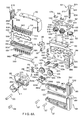
- FIG. 8( a ) is an exploded view of a cutting and stapling attachment according to one example embodiment of the present invention.
- FIG. 8( b ) is an exploded view of a cutting and stapling attachment according to another example embodiment of the present invention.
- FIG. 9( a ) is a perspective view of the cutting and stapling attachment illustrated in FIG. 8( a );
- FIG. 9( b ) is a perspective view of the cutting and stapling attachment illustrated in FIG. 8( b );
- FIG. 10 is a side elevational view, partially in section, of a flexible shaft of the electro-mechanical surgical device illustrated in FIG. 2 ;
- FIG. 11 is a cross-sectional view of the flexible shaft taken along the line 11 - 11 shown in FIG. 10 ;
- FIG. 12 is a rear end view of a first coupling of the flexible shaft illustrated in FIG. 10 ;
- FIG. 13 is a front end view of a second coupling of the flexible shaft illustrated in FIG. 10 ;
- FIG. 14 is a schematic view of a motor arrangement of the electro-mechanical surgical system illustrated in FIG. 2 ;
- FIG. 15 is a schematic view of the electro-mechanical surgical system illustrated in FIG. 2 ;
- FIG. 16 is a schematic view of an encoder of the flexible shaft illustrated in FIG. 10 ;
- FIG. 17 is a schematic view of a memory device of a linear clamping, cutting and stapling device according to one example embodiment of the present invention.
- FIG. 18 is a schematic view of a wireless remote control unit of the electro-mechanical surgical system illustrated in FIG. 2 ;
- FIG. 19 is a schematic view of a wired remote control unit of the electro-mechanical surgical system illustrated in FIG. 2 ;
- FIGS. 20( a ) to 20 ( c ) illustrate a flowchart of a main operating program, the steps of which are performed during the operation of the surgical device in accordance with one example embodiment of the present invention
- FIGS. 21( a ) to 21 ( c ) illustrate a flowchart of a jaw-closing routine of the main operating program illustrated in FIGS. 20( a ) to 20 ( c ) in accordance with one example embodiment of the present invention
- FIGS. 22( a ) to 22 ( c ) illustrate a flowchart of a calibration routine of the main operating program illustrated in FIGS. 20( a ) to 20 ( c ) in accordance with one example embodiment of the present invention
- FIG. 23 illustrates a flowchart of a jaw opening routine of the main operating program illustrated in FIGS. 20( a ) to 20 ( c ) in accordance with one example embodiment of the present invention
- FIGS. 24( a ) to 24 ( c ) illustrate a flowchart of a clamping, cutting and stapling routine of the main operating program illustrated in FIGS. 20( a ) to 20 ( c ) in accordance with one example embodiment of the present invention.
- FIGS. 25( a ) to 25 ( b ) illustrate a flowchart of a testing routine of the main operating program illustrated in FIGS. 20( a ) to 20 ( c ) in accordance with one example embodiment of the present invention.
- FIGS. 3 to 7 One example embodiment of a surgical device 11 according to the present invention is illustrated in FIGS. 3 to 7 .
- an example embodiment of the surgical device 11 e.g., a clamping, cutting and stapling device, is illustrated.
- the surgical device 11 includes a parallel separating jaw system having a second jaw 50 in opposite correspondence to a first jaw 80 .
- a first end 50 a of second jaw 50 is mechanically coupled to a first end 80 a of first jaw 80 .
- the opposing jaws 50 and 80 may remain parallel relative to each other.
- opposing jaws 50 and 80 may open and close in scissor-like fashion, wherein the first ends 50 a and 80 a of the second jaw 50 and the first jaw 80 are mechanically connected by a hinge or other rotational element such that the first jaw 80 is rotatably coupled to the second jaw 50 .
- FIG. 3 illustrates the surgical device 11 in an open position, wherein the second jaw 50 and the first jaw 80 are in contact with each other at their first ends 50 a and 80 a .
- the first jaw 80 and the second jaw 50 are maintained and move in a longitudinal plane defined by the x and y axes illustrated in FIG. 3 .
- Mounted on a side of the first jaw 80 a is a gear housing 255 .
- the gear housing 255 includes a first drive socket 180 coupled to a first driver 150 , which for purposes of clarity is illustrated schematically.
- the first driver 150 is coupled to a first end 50 a of the second jaw 50 to open and close the first jaw 80 and the second jaw 50 .
- the gear housing 255 also includes a second drive socket 310 .
- FIG. 4 illustrates the surgical device 11 in a closed position.
- the second jaw 50 and the first jaw 80 are in contact with each other at their first ends 50 a and 80 a and also at their second ends 50 a and 50 b .
- a section of tissue is clamped between the second jaw 50 and the first jaw 80 .
- FIGS. 5 and 6 also illustrate the surgical device 11 in the closed position.
- FIGS. 5 and 6 illustrate the second drive socket 310 of the gear housing 255 coupled to a second driver 261 , which is illustrated schematically.
- the second driver 261 is coupled to a surgical member 262 .
- the surgical member 262 may include a cutting and stapling assembly 262 , although other types of surgical members may be provided.
- the second driver 261 is coupled to cutting and stapling assembly 262 to move the cutting and stapling assembly 262 from a first retracted position, as illustrated in FIG. 5 , to a second extended position, as illustrated in FIG. 6 .
- two drive sockets e.g., the first drive socket 180 and the second drive socket 310
- two corresponding drive shafts e.g., the first drive shaft 630 and the second drive shaft 632
- a single drive shaft may be provided to drive the surgical device.
- FIG. 7 is a top view of the surgical device 11 illustrated in FIGS. 3 to 6 .
- FIG. 7 illustrates the surgical device 11 coupled, e.g., removably or permanently, to an electro-mechanical driver component 610 .
- FIG. 7 illustrates the surgical device 11 including the first driver 150 , which is coupled via first drive socket 180 to a first motor 680 of the system 610 by a first drive shaft 630 .
- the first driver 150 when engaged by system 610 , operates to open and close the first jaw 80 relative to the second jaw 50 .
- FIG. 7 illustrates the surgical device 11 including a second driver 261 , which is coupled via the second drive socket 310 to a second motor 676 of system 610 by a second drive shaft 632 .
- the second driver 261 when engaged by the system 610 , operates to drive a cutting and stapling assembly 262 .
- the first drive socket 180 and the second drive socket 310 are disposed on the surgical device 11 so that the first drive shaft 630 and the second drive shaft 632 are coupled to the surgical device 11 at an angle, e.g., perpendicularly, to the x-y plane illustrated in FIG. 3 . That is, the first drive shaft 630 and the second drive shaft 632 are coupled to the surgical device 11 in the direction of the z-axis illustrated in FIG. 7 .
- FIG. 8( a ) is an exploded view of the surgical device 11 according to one example embodiment of the present invention
- FIG. 9( a ) is a perspective view of the surgical device 11 assembled.
- the second jaw 50 includes an anvil 505 , which is coupled to an anvil filler 509 by fasteners 527 , e.g., rivets.
- the anvil 505 includes a vertically-disposed, internally-threaded bore 5051 at its upper end 5052 .
- the anvil 505 includes a plurality of staple guides 5053 in a parallel-disposed arrangement along a region 5054 of the anvil 505 that is in opposite correspondence to first jaw 80 .
- a knife pad 520 is disposed between the plurality of staple guides 5053 .
- the first jaw 80 includes a housing frame 506 .
- the housing frame 506 includes a pair of internally disposed guides 5061 along which a pair of ribs 5055 of the anvil 505 may travel, so that the housing frame 506 may move parallel with, and in opposite correspondence to, the anvil 505 .
- a gear housing 255 is mounted to one side 5062 of the housing frame 506 via fasteners 533 and 534 , e.g., screws.
- a quick-connect coupling 511 is mounted onto the gear housing 255 and is biased via a set of springs 538 .
- the gear housing 255 includes the first drive socket 180 and the second drive socket 310 .
- the first drive socket 180 includes the first pinion 508 a , one end 5081 of which extends through an opening 2551 of the gear housing 255 and the other end 5082 of which includes spur gear teeth 5083 .
- the second drive socket 310 includes the second pinion 508 b , one end 5084 of which extends through a second opening 2552 of the gear housing 255 and the other end 5085 of which includes spur gear teeth 5086 .
- a memory module 501 is arranged in the gear housing 255 and includes a connector 2554 that extends through, or is accessible through, an opening 2553 of the gear housing 255 .
- the memory module 501 is maintained in position within the gear housing 255 by an inboard shim 530 and an outboard shim 531 .
- the memory module 501 is also biased in its position by a spring 539 .
- the first and second pinions 508 a and 508 b engages a respective spur gears 529 a and 529 b .
- the first spur gear 529 a includes an internal bore 5293 which non-rotatably engages an end 5231 of the first worm 523 a .
- the second spur gear 529 b includes an internal bore 5294 which non-rotatably engages an end 5234 of the second worm 523 b .
- the bores 5293 and 5294 and the ends 5231 , 5234 may be, e.g., square. It should be understood that the bores 5293 , 5294 and the ends 5231 , 5234 may have any shape or configuration that provides non-rotatable engagement therebetween.
- the first worm 523 a has one end 5231 , which non-rotatably engages the internal bore 5293 of the first spur gear 529 a , and a second end 5232 , which includes circumferentially-disposed thread(s) 5233 .
- the second worm 523 b has one end 5234 , which non-rotatably engages the internal bore 5294 of the second spur gear 529 b , and a second end 5235 which includes circumferentially-disposed threads 5236 .
- the second end 5232 of the first worm 523 a is disposed within the frame housing 506 , and the end 5231 of the worm 523 a extends through a hole 5063 in the side of the frame housing 506 to engage the first spur gear 529 a in the gear housing 255 .
- the second end 5235 of the second worm 523 b is disposed within the frame housing 506 , and the end 5234 of the worm 523 b extends through a hole 5064 in the side of the frame housing 506 to engage the second spur gear 529 b in the gear housing 255 .
- Worm gear 522 has circumferentially-disposed teeth 5221 , which engage the thread(s) 5233 of the second end 5232 of the worm 523 a .
- the worm gear 522 includes an internal bore 5222 through which is disposed a screw 521 .
- the screw 521 has a head 5211 with a portion 5212 , which non-rotatably engages the internal bore 5222 of worm gear 522 .
- the internal bore 5222 and the portion 5212 of the screw 521 may be complementary, e.g., square.
- the screw 521 also includes a portion 5213 of the head 5211 that extends through a washer 537 and a hole 5351 in a bearing plate 535 .
- the screw 521 also has externally-disposed threads 5214 , which engage the internally-threaded bore 5051 of the anvil 505 .
- a worm gear 516 and a worm gear 517 are disposed within the frame housing 506 .
- the worm gear 516 and the worm gear 517 are positioned on opposite sides of the worm 523 b .
- the worm gear 516 includes circumferentially-disposed gear teeth 5161 , which engage a first side of the worm 523 b
- the worm gear 517 includes circumferentially-disposed gear teeth 5171 , which engage a second side of the worm 523 b
- the worm gear 516 includes a cylindrical projection 5162 , which extends through a hole 5352 in the bearing plate 535 .
- Retaining ring 536 a engages a groove 5163 of the cylindrical projection 5162 so that the worm gear 516 is rotatable about its vertical central axis 5165 relative to the bearing plate 535 .
- the worm gear 517 includes a cylindrical projection 5172 , which extends through a hole 5353 in the bearing plate 535 .
- Retaining ring 536 b engages a groove 5173 of the cylindrical projection 5172 so that the worm gear 517 is rotatable about its vertical central axis 5175 relative to the bearing plate 535 .
- An externally-threaded screw 504 is disposed through an internally-threaded bore 5164 of the worm gear 516 .
- An externally-threaded screw 503 is disposed through an internally-threaded bore 5174 of worm gear 517 . Because the worm gears 516 and 517 are located on, and engage, opposite sides of the worm 523 b , the internally-threaded bores 5164 and 5174 of the worm gears 516 and 517 , as well as the externally-threaded screws 504 and 503 , may be oppositely threaded relative to each other.
- the internally-threaded bore 5164 of the worm gear 516 may have a right-hand thread, which engages the right-hand external thread of the screw 504
- the internally-threaded bore 5174 of the worm gear 517 may have a left-handed thread, which engages the left-handed external thread of the screw 503 .
- Both the screws 503 and 504 are fixedly coupled to a top surface 5021 of a thrust plate 502 .
- the thrust plate 502 is positioned between the opposite sides of the housing frame 506 .
- a staple pusher 514 is attached to a bottom surface 5022 of the thrust plate 502 .
- the staple pusher 514 includes parallel rows 5141 and 5142 of downwardly-disposed teeth 5143 , each of which corresponds to and aligns with a staple guide 5053 of the anvil 505 .
- a knife 519 having a cutting edge 5191 facing downwardly is disposed between the parallel rows of downwardly-disposed teeth 5143 of the staple pusher 514 .
- a staple holder 513 is disposed below the staple pusher 514 .
- the staple holder 513 includes a cartridge having vertically-disposed slots 5132 , each of which corresponds to and aligns with the downwardly-disposed teeth 5143 of the staple pusher 514 and with the staple guides 5053 of the anvil 505 .
- a staple 228 which includes prongs 5281 , is provided in each slot 5132 .
- the staple holder 513 also includes a longitudinally-disposed slot 5131 , which extends through the staple holder 513 and through which knife 519 may be passed.
- the staple holder 513 includes a hole 5133 adjacent to one end 5134 .
- a staple retainer 540 is attached to the lower parallel edges 5066 of the frame housing 506 or to a bottom surface of the staple holder 513 .
- the staple retainer 540 is configured to cover the bottom surface of the staple holder 513 so as to maintain the staples 528 within the staple holder 513 and to prevent foreign material from entering the slots 5132 of the staple holder 513 during shipping of the surgical device 11 .
- the staple retainer 540 has a through-hole 5401 having a tapered or beveled edge 5402 .
- the staple retainer 540 also has a grip region 5403 that is configured to be gripped by a user.
- the hole 5133 of the staple holder 513 that is adjacent to the one end 5134 of the staple holder 513 is configured to receive an end 5181 of a pin 518 .
- the end 5181 of the pin 518 is tapered so as to seat against the tapered edge 5402 of the through-hole 5401 of the staple retainer 540 .
- the pin 518 is maintained in a substantially vertical position so as to be perpendicular to the staple holder 513 .
- the pin 518 includes a centrally-disposed internal bore 5183 at its opposite end 5184 configured to receive a spring 524 .
- a lever 5182 which is attached perpendicularly to the pin 518 .
- a cartridge cap 515 is attached, such as by welding, to an end 5067 of the frame housing 506 . Latches 5151 and 5152 of the cartridge cap 515 engage notches 5068 of the housing frame 506 .
- the cartridge cap 515 also includes an internally-disposed bore 5154 which is configured to receive pin 518 . Bore 5154 of the cartridge cap 515 includes a slot 5153 in communication therewith, the slot 5153 configured to guide the lever 5182 of the pin 518 .
- the internally-disposed bore 5154 of the cartridge cap 515 does not extend through the top surface 5155 of the cartridge cap 515 ; instead, it maintains the spring 524 within the internally-disposed bore 5154 .
- the biasing force of the spring 524 pushes the end 5181 of the pin 518 into the hole 5133 of the staple holder 513 and tends to ensure that the staple holder 513 is positioned so that the slots 5132 align with the downwardly-disposed teeth 5143 of the staple pusher 514 and with the staple guides 5053 of the anvil 505 .
- the cartridge cap 515 is also maintained in position by a latch 526 , which is pivotably attached to the housing frame 506 by fasteners 507 .
- a housing top 510 is arranged between the opposite sides 5062 and 5065 of the housing frame 506 and protects the components within the housing frame 506 .
- the example embodiment illustrated in FIG. 8( a ) includes a thin flat staple retainer 540 .
- This configuration of the staple retainer 540 is adapted to maintain the staples 528 in the staple holder 513 when the surgical device is initially maintained in the closed position, e.g., when the surgical device 11 is initially shipped to a user such that the first jaw 80 and the second jaw 50 contact opposite sides of the staple retainer 540 .
- This configuration of the staple retainer 540 ensure that, during transportation, the staples 528 are maintained within the staple holder 513 and prevents damage to the staples 528 and to the staple guides 5053 of the anvil 505 .
- the surgical device 11 may initially be maintained in the open position.
- FIG. 8( b ) is an exploded view of the surgical device 11 , according to one example embodiment of the present invention
- FIG. 9( b ) is a perspective view of the surgical device 11 illustrated in FIG. 8( b ) assembled. More specifically, FIG. 8( b ) illustrates the surgical device 11 having a staple retainer 525 configured to initially maintain the surgical device 11 in the open position, e.g., when the surgical device 11 is initially shipped to a user such that the first jaw 80 and the second jaw 50 are separated.
- the staple retainer 525 is attached via tabs 5251 to the lower parallel edges 5066 of the frame housing 506 and is configured to maintain the staples 528 within the staple holder 513 and to prevent damage to the staples 528 and to the staple guides 5053 of the anvil 505 during transportation.
- the staple retainer 525 includes a pair of guides 5254 positioned along the side edges 5253 a and 5253 b and which extend downwardly. Guides 5254 are configured to contact the outer sides 5056 of the anvil 505 so as to maintain the first jaw 80 , e.g., the housing frame 506 , etc., of the surgical device 11 in parallel correspondence with the second jaw 50 during the shipping and handling process.
- the guides 5254 may prevent misalignment of the first jaw 80 and second jaw 50 that may occur when the surgical device 11 is transported with the first jaw 80 and the second jaw 50 in the open position.
- FIGS. 3 to 9( b ) include a guillotine-type arrangement of the stapling and cutting elements
- a stapling and cutting element is moved between a proximal end and a distal end of the surgical device 11
- an alternative example embodiment of the surgical device 11 may include gears coupled to a stapling and cutting element that is moved between a proximal end and a distal end of the surgical device 11 , the gears driven by drive shafts that are coupled in non-parallel, e.g., perpendicular, correspondence to the plane of movement of the first jaw 80 and the second jaw 50 .
- the surgical device 11 may be configured as an attachment to, or may be integral with, an electro-mechanical surgical system, such as electro-mechanical driver component 610 .
- the surgical device may be an attachment to, or may integral with, a mechanical driver system.
- FIG. 2 is a perspective view of an example embodiment of an electro-mechanical driver component 610 according to the present invention.
- an electro-mechanical driver component examples are described in, e.g., U.S. patent application Ser. No. 09/723,715 (now U.S. Pat. No. 6,793,652), U.S. patent application Ser. No. 09/836,781 (now U.S. Pat. No. 6,981,941) and U.S. patent application Ser. No. 09/887,789 (now U.S. Pat. No. 7,032,798), each of which is expressly incorporated herein in their entirety by reference thereto.
- Electro-mechanical driver component 610 may include, for example, a remote power console 612 , which includes a housing 614 having a front panel 615 . Mounted on front panel 615 are a display device 616 and indicators 618 a , 618 b .
- a flexible shaft 620 may extend from housing 614 and may be detachably attached thereto via a first coupling 622 .
- the distal end 624 of flexible shaft 620 may include a second coupling 626 adapted to detachably attach, e.g., the surgical device 11 described above, to the distal end 624 of flexible shaft 620 .
- the second coupling 626 may also be adapted to detachably attach a different surgical instrument or attachment.
- the distal end 624 of the flexible shaft 620 may permanently attach to or be integral with a surgical instrument.
- flexible shaft 620 includes a tubular sheath 628 , which may include a coating or other sealing arrangement configured to provide a fluid-tight seal between the interior channel 640 thereof and the environment.
- Sheath 628 may be formed of a tissue-compatible, sterilizable elastomeric material.
- the sheath 628 may also be formed of a material that is autoclavable.
- FIG. 11 is a cross-sectional view of flexible shaft 620 taken along the line 11 - 11 illustrated in FIG. 10 and further illustrates the several cables 630 , 632 , 634 , 635 , 636 , 637 , 638 .
- Each distal end of the steering cables 634 , 635 , 636 , 637 is affixed to the distal end 624 of the flexible shaft 620 .
- Each of the several cables 630 , 632 , 634 , 635 , 636 , 637 , 638 may be contained within a respective sheath.
- the first rotatable drive shaft 630 and the second rotatable drive shaft 632 may be configured, for example, as highly flexible drive shafts, such as, for example, braided or helical drive cables. It should be understood that such highly flexible drive cables may have limited torque transmission characteristics and capabilities. It should also be understood that the surgical device 11 , or other attachments connected to the flexible shaft 620 , may require a higher torque input than the torque transmittable by the drive shafts 630 , 632 .
- the drive shafts 630 , 632 may thus be configured to transmit low torque but high speed, the high-speed/low-torque being converted to low-speed/high-torque by gearing arrangements disposed, for example, at the distal end and/or the proximal end of the drive flexible shaft 620 , in the surgical instrument or attachment and/or in the remote power console 612 .
- gearing arrangement(s) may be provided at any suitable location along the power train between the motors disposed in the housing 614 and the attached surgical instrument or other attachment connected to the flexible shaft 620 .
- Such gearing arrangement(s) may include, for example, a spur gear arrangement, a planetary gear arrangement, a harmonic gear arrangement, cycloidal drive arrangement, an epicyclic gear arrangement, etc.
- FIG. 12 there is seen a rear end view of first coupling 622 .
- First coupling 622 includes a first connector 644 , a second connector 648 , a third connector 652 and a fourth connector 656 , each rotatably secured to first coupling 622 .
- Each of the connectors 644 , 648 , 652 , 656 includes a respective recess 646 , 650 , 654 , 658 . As illustrated in FIG. 12 , each recess 646 , 650 , 654 , 658 may be hexagonally shaped.
- the recesses 646 , 650 , 654 , 658 may have any shape and configuration adapted to non-rotatably couple and rigidly attach the connectors 644 , 648 , 652 , 656 to respective drive shafts of the motor arrangement contained within the housing 612 .
- complementary projections may be provided on respective drive shafts of the motor arrangement to thereby drive the drive elements of the flexible shaft 620 .
- the recesses may be provided on the drive shafts and complementary projections may be provided on the connectors 644 , 648 , 652 , 656 . Any other coupling arrangement configured to non-rotatably and releasably couple the connectors 644 , 648 , 652 , 656 and the drive shafts of the motor arrangement may be provided.
- One of the connectors 644 , 648 , 652 , 656 is non-rotatably secured to the first drive shaft 630
- another one of the connectors 644 , 648 , 652 , 656 is non-rotatably secured to the second drive shaft 632 .
- the remaining two of the connectors 644 , 648 , 652 , 656 engage with transmission elements configured to apply tensile forces on the steering cables 634 , 635 , 636 , 637 to thereby steer the distal end 624 of the flexible shaft 620 .
- the data transfer cable 638 is electrically and logically connected with data connector 660 .
- Data connector 660 includes, for example, electrical contacts 662 , corresponding to and equal in number to the number of individual wires contained in the data cable 638 .
- First coupling 622 includes a key structure 642 configured to properly orient the first coupling 622 to a mating and complementary coupling arrangement disposed on the housing 612 .
- Such key structure 642 may be provided on either one, or both, of the first coupling 622 and the mating and complementary coupling arrangement disposed on the housing 612 .
- First coupling 622 may include a quick-connect type connector, which may engage the first coupling 622 to the housing 612 by a simple pushing motion. Seals may be provided in conjunction with any of the several connectors 644 , 648 , 652 , 656 , 660 to provide a fluid-tight seal between the interior of first coupling 622 and the environment.
- the second coupling 626 includes a first connector 666 and a second connector 668 , each rotatably secured to the second coupling 626 and each non-rotatably secured to a distal end of a respective one of the first and second drive shafts 630 , 632 .
- a quick-connect type fitting 664 is provided on the second coupling 626 to detachably secure the device 11 thereto.
- the quick-connect type fitting 664 may be, for example, a rotary quick-connect type fitting, a bayonet type fitting, etc.
- a key structure 674 is provided on the second coupling 626 and configured to properly align the device 11 to the second coupling 626 .
- the key structure or other arrangement configured to properly align the device 11 to the flexible shaft 620 may be provided on either one, or both, of the second coupling 626 and the device 11 .
- the quick-connect type fitting may be provided on the device 11 , as illustrated in FIG. 8( a ) as the quick connect coupling 511 .
- a data connector 670 having electrical contacts 672 is also provided in the second coupling 626 .
- the data connector 670 of second coupling 626 includes contacts 672 electrically and logically connected to the respective wires of data transfer cable 638 and contacts 662 of data connector 660 . Seals may be provided in conjunction with the connectors 666 , 668 , 670 to provide a fluid-tight seal between the interior of second coupling 626 and the environment.
- electro-mechanical driver elements Disposed within housing 614 of the remote power console 612 are electro-mechanical driver elements configured to drive the drive shafts 630 , 632 and the steering cables 634 , 635 , 636 , 637 to thereby operate the electro-mechanical driver component 610 and the surgical device 11 attached to the second coupling 626 .
- five electric motors 676 , 680 , 684 , 690 , 696 may be disposed in the remote power console 612 . It should be appreciated, however, that any appropriate number of motors may be provided, and the motors may operate via battery power, line current, a DC power supply, an electronically controlled DC power supply, etc. It should also be appreciated that the motors may be connected to a DC power supply, which is in turn connected to line current and which supplies the operating current to the motors.
- FIG. 14 illustrates schematically one possible arrangement of motors.
- An output shaft 678 of a first motor 676 engages with the first connector 644 of the first coupling 622 when the first coupling 622 , and, therefore, flexible shaft 620 , is engaged with the housing 614 to thereby drive the first drive shaft 630 and first connector 666 of second coupling 626 .
- an output shaft 682 of a second motor 680 engages the second connector 648 of first coupling 622 when first coupling 622 , and, therefore, flexible shaft 620 is engaged with the housing 614 to thereby drive the second drive shaft 632 and second connector 668 of second coupling 626 .
- An output shaft 686 of a third motor 684 engages the third connector 652 of the first coupling 622 when the first coupling 622 , and, therefore, flexible shaft 620 , is engaged with the housing 614 to thereby drive the first and second steering cables 634 , 635 via a first pulley arrangement 688 .
- An output shaft 692 of a fourth motor 690 engages the fourth connector 656 of the first coupling 622 when the first coupling 622 , and, therefore, flexible shaft 620 , is engaged with the housing 614 to thereby drive the third and fourth steering cables 636 , 637 via a second pulley arrangement 694 .
- the third and fourth motors 684 , 690 may be secured on a carriage 1100 , which is selectively movable via an output shaft 698 of a fifth motor 696 between a first position and a second position to selectively engage and disengage the third and fourth motors 684 , 690 with the respective pulley arrangement 688 , 694 to thereby permit the flexible shaft 620 to become taut and steerable or limp as necessary.
- the motors may be arranged and configured as described, for example, in U.S. patent application Ser. No. 09/510,923, entitled A Carriage Assembly for Controlling a Steering Wire Mechanism Within a Flexible Shaft,” (now U.S. Pat. No. 6,517,565) which is expressly incorporated herein in its entirety by reference thereto.
- any one or more of the motors 676 , 680 , 684 , 690 , 696 may be, for example, a high-speed/low-torque motor, a low-speed/high-torque motor, etc.
- the first rotatable drive shaft 630 and the second rotatable drive shaft 632 may be configured to transmit high speed and low torque.
- the first motor 676 and the second motor 680 may be configured as high-speed/low-torque motors.
- first motor 676 and the second motor 680 may be configured as low-speed/high-torque motors with a torque-reducing/speed-increasing gear arrangement disposed between the first motor 676 and the second motor 680 and a respective one of the first rotatable drive shaft 630 and the second rotatable drive shaft 632 .
- torque-reducing/speed-increasing gear arrangements may include, for example, a spur gear arrangement, a planetary gear arrangement, a harmonic gear arrangement, cycloidal drive arrangement, an epicyclic gear arrangement, etc.
- any such gear arrangement may be disposed within the remote power console 612 or in the proximal end of the flexible shaft 620 , such as, for example, in the first coupling 622 . It should be appreciated that the gear arrangement(s) may be provided at the distal and/or proximal ends of the first rotatable drive shaft 630 and/or the second rotatable drive shaft 632 to prevent windup and breakage thereof.
- a controller 1122 is provided in the housing 614 of remote power console 612 and is configured to control all functions and operations of the electro-mechanical driver component 610 and the linear clamping, cutting and stapling device 11 or other surgical instrument or attachment attached to the flexible shaft 620 .
- a memory unit 1130 is provided and may include memory devices, such as, a ROM component 1132 , a RAM component 1134 , etc. ROM component 1132 is in electrical and logical communication with controller 1122 via line 1136 , and RAM component 1134 is in electrical and logical communication with controller 1122 via line 1138 .
- RAM component 1134 may include any type of random-access memory, such as, for example, a magnetic memory device, an optical memory device, a magneto-optical memory device, an electronic memory device, etc.
- ROM component 1132 may include any type of read-only memory, such as, for example, a removable memory device, such as a PC-Card or PCMCIA-type device. It should be appreciated that ROM component 1132 and RAM component 1134 may be configured as a single unit or may be separate units and that ROM component 1132 and/or RAM component 1134 may be provided in the form of a PC-Card or PCMCIA-type device.
- Controller 1122 is further connected to front panel 615 of housing 614 and, more particularly, to display device 616 via line 1154 and indicators 618 a , 618 b via respective lines 1156 , 1158 .
- Lines 1116 , 1118 , 1124 , 1126 , 1128 electrically and logically connect controller 1122 to first, second, third, fourth and fifth motors 676 , 680 , 684 , 690 , 696 , respectively.
- a wired remote control unit (“RCU”) 1150 is electrically and logically connected to controller 1122 via line 1152 .
- a wireless RCU 1148 is also provided and communicates via a wireless link 1160 with a receiving/sending unit 1146 connected via line 1144 to a transceiver 1140 .
- the transceiver 1140 is electrically and logically connected to controller 1122 via line 1142 .
- Wireless link 1160 may be, for example, an optical link, such as an infrared link, a radio link or
- a switch device 1186 which may include, for example, an array of DIP switches, may be connected to controller 1122 via line 1188 .
- Switch device 1186 may be configured, for example, to select one of a plurality of languages used in displaying messages and prompts on the display device 616 .
- the messages and prompts may relate to, for example, the operation and/or the status of the electro-mechanical driver component 610 and/or to the surgical device 11 attached thereto.
- a first encoder 1106 is provided within the second coupling 626 and is configured to output a signal in response to and in accordance with the rotation of the first drive shaft 630 .
- a second encoder 1108 is also provided within the second coupling 626 and is configured to output a signal in response to and in accordance with the rotation of the second drive shaft 632 .
- the signal output by each of the encoders 1106 , 1108 may represent the rotational position of the respective drive shaft 630 , 632 as well as the rotational direction thereof.
- Such encoders 1106 , 1108 may include, for example, Hall-effect devices, optical devices, etc.
- the encoders 1106 , 1108 are described as being disposed within the second coupling 626 , it should be appreciated that the encoders 1106 , 1108 may be provided at any location between the motor system and the surgical device 11 . It should be appreciated that providing the encoders 1106 , 1108 within the second coupling 626 or at the distal end of the flexible shaft 620 may provide an accurate determination of the drive shaft rotation. If the encoders 1106 , 1108 are disposed at the proximal end of the flexible shaft 620 , windup of the first and second rotatable drive shafts 630 , 632 may result in measurement error.
- FIG. 16 is a schematic view of an encoder 1106 , 1108 , which includes a Hall-effect device.
- a magnet 1240 having a north pole 1242 and a south pole 1244 .
- the encoder 1106 , 1108 further includes a first sensor 1246 and second sensor 1248 , which are disposed approximately 90° apart relative to the longitudinal, or rotational, axis of drive shaft 630 , 632 .
- the output of the sensors 1246 , 1248 is persistent and changes its state as a function of a change of polarity of the magnetic field in the detection range of the sensor.
- the angular position of the drive shaft 630 , 632 may be determined within one-quarter revolution and the direction of rotation of the drive shaft 630 , 632 may be determined.
- the output of each encoder 1106 , 1108 is transmitted via a respective line 1110 , 1112 of data transfer cable 638 to controller 1122 .
- the controller 1122 by tracking the angular position and rotational direction of the drive shafts 630 , 632 based on the output signal from the encoders 1106 , 1108 , may thereby determine the position and/or state of the components of the surgical device connected to the electro-mechanical driver component 610 . That is, by counting the revolutions of the drive shaft 630 , 632 , the controller 1122 may determine the position and/or state of the components of the surgical device connected to the electro-mechanical driver component 610 .
- the advancement distance between the first jaw 80 and the second jaw 50 and the thrust plate 502 are functions of, and ascertainable on the basis of, the rotation of the respective drive shafts 630 , 632 .
- the relative displacement of the second jaw 50 and the thrust plate 502 may be used to ascertain the absolute position of the first jaw 80 and the thrust plate 502 at all times thereafter.
- the absolute position of the second jaw 50 and the thrust plate 502 may be fixed and ascertained at the time that the surgical device 11 is first coupled to the flexible shaft 620 .
- the position of the second jaw 50 and the thrust plate 502 relative to, for example, the first jaw 80 may be determined based on the output signal from the encoders 1106 , 1108 .
- the surgical device 11 may further include, as illustrated in FIG. 8( a ), a data connector 1272 adapted by size and configuration to electrically and logically connect to connector 670 of second coupling 626 .
- data connector 1272 includes contacts equal in number to the number of leads 672 of connector 670 .
- the memory module 501 is electrically and logically connected with the data connector 1272 .
- Memory module 501 may be in the form of, for example, an EEPROM, EPROM, etc. and may be contained, for example, within the second jaw 50 of the surgical device 11 .
- FIG. 17 schematically illustrates the memory module 501 .
- data connector 1272 includes contacts 1276 , each electrically and logically connected to the memory module 501 via a respective line 1278 .
- the memory module 501 may be configured to store, for example, a serial number data 1180 , an attachment type identifier (ID) data 1182 and a usage data 1184 .
- the memory module 501 may additionally store other data. Both the serial number data 1180 and the ID data 1182 may be configured as read-only data. The serial number data 1180 and/or the ID data 1182 may be stored in a read-only section of the memory module 501 .
- serial number data 1180 may be data uniquely identifying the particular surgical device
- ID data 1182 may be data identifying the type of the attachment, such as, for example, in a system 610 in which other types of surgical instruments or attachments are attachable thereto.
- the usage data 1184 represents usage of the particular attachment, such as, for example, the number of times the first jaw 80 of the surgical device 11 has been opened and closed, or the number of times that the thrust plate of the surgical device 11 has been advanced.
- the usage data 1184 may be stored in a read/write section of the memory module 501 .
- the attachment attachable to the distal end 624 of the flexible shaft 620 may be designed and configured to be used a single time or multiple times.
- the attachment may also be designed and configured to be used a predetermined number of times.
- the usage data 1184 may be used to determine whether the surgical device 11 has been used and whether the number of uses has exceeded the maximum number of permitted uses. As more fully described below, an attempt to use the attachment after the maximum number of permitted uses has been reached will generate an ERROR condition.
- the controller 1122 is configured to read the ID data 1182 from the memory module 501 of the surgical device 11 when the surgical device 11 is initially connected to the flexible shaft 620 .
- the memory module 501 is electrically and logically connected to the controller 1122 via the line 1120 of the data transfer cable 638 .
- the controller 1122 is configured to read or select from the memory unit 1130 , an operating program or algorithm corresponding to the type of surgical instrument or attachment connected to the flexible shaft 620 .
- the memory unit 1130 is configured to store the operating programs or algorithms for each available type of surgical instrument or attachment, the controller 1122 selecting and/or reading the operating program or algorithm from the memory unit 1130 in accordance with the ID data 1182 read from the memory module 501 of an attached surgical instrument or attachment.
- the memory unit 1130 may include a removable ROM component 1132 and/or RAM component 1134 .
- the operating programs or algorithms stored in the memory unit 1130 may be updated, added, deleted, improved or otherwise revised as necessary.
- the operating programs or algorithms stored in the memory unit 1130 may be customizable based on, for example, specialized needs of the user.
- a data entry device such as, for example, a keyboard, a mouse, a pointing device, a touch screen, etc., may be connected to the memory unit 1130 via, for example, a data connector port, to facilitate the customization of the operating programs or algorithms.
- the operating programs or algorithms may be customized and preprogrammed into the memory unit 1130 remotely from the electro-mechanical driver component 610 .
- the serial number data 1180 and/or usage data 1184 may also be used to determine which of a plurality of operating programs or algorithms is read or selected from the memory unit 1130 .
- the operating program or algorithm may alternatively be stored in the memory module 501 of the surgical device 11 and transferred to the controller 1122 via the data transfer cable 638 .
- the controller 1122 causes the operating program or algorithm to be executed in accordance with operations performed by the user via the wired RCU 1150 and/or the wireless RCU 1148 .
- the controller 1122 is electrically and logically connected with the first, second, third, fourth and fifth motors 676 , 680 , 684 , 690 , 696 via respective lines 1116 , 1118 , 1124 , 1126 , 1128 and is configured to control such motors 676 , 680 , 684 , 690 , 696 in accordance with the read, selected or transmitted operating program or algorithm via the respective lines 1116 , 1118 , 1124 , 1126 , 1128 .
- Wireless RCU 1148 includes a steering controller 1300 having a plurality of switches 1302 , 1304 , 1306 , 1308 arranged under a four-way rocker 1310 .
- the operation of switches 1302 , 1304 , via rocker 1310 controls the operation of first and second steering cables 634 , 635 via third motor 684 .
- the operation of switches 1306 , 1308 , via rocker 1310 controls the operation of third and fourth steering cables 636 , 637 via fourth motor 692 .
- rocker 1310 and switches 1302 , 1304 , 1306 , 1308 are arranged so that the operation of switches 1302 , 1304 steers the flexible shaft 620 in the north-south direction and that the operation of switches 1306 , 1308 steers the flexible shaft 620 in the east-west direction.
- Reference herein to north, south, east and west is made to a relative coordinate system.
- a digital joystick, an analog joystick, etc. may be provided in place of rocker 1310 and switches 1302 , 1304 , 1306 , 1308 .
- Potentiometers or any other type of actuator may also be used in place of switches 1302 , 1304 , 1306 , 1308 .
- Wireless RCU 1148 further includes a steering engage/disengage switch 1312 , the operation of which controls the operation of fifth motor 696 to selectively engage and disengage the steering mechanism.
- Wireless RCU 1148 also includes a two-way rocker 1314 having first and second switches 1316 , 1318 operable thereby. The operation of these switches 1316 , 1318 controls certain functions of the electro-mechanical driver component 610 and any surgical instrument or attachment, such as the surgical device 11 , attached to the flexible shaft 620 in accordance with the operating program or algorithm corresponding to the attached device 11 .
- operation of the two-way rocker 1314 may control the opening and closing of the first jaw 80 and the second jaw 50 of the surgical device 11 .
- Wireless RCU 1148 is provided with yet another switch 1320 , the operation of which may further control the operation of the electro-mechanical driver component 610 and the device attached to the flexible shaft 620 in accordance with the operating program or algorithm corresponding to the attached device. For example, operation of the switch 1320 may initiate the advancement of the thrust plate 502 of the surgical device 11 .
- Wireless RCU 1148 includes a controller 1322 , which is electrically and logically connected with the switches 1302 , 1304 , 1306 , 1308 via line 1324 , with the switches 1316 , 1318 via line 1326 , with switch 1312 via line 1328 and with switch 1320 via line 1330 .
- Wireless RCU 1148 may include indicators 618 a ′, 618 b ′, corresponding to the indicators 618 a , 618 b of front panel 615 , and a display device 616 ′, corresponding to the display device 616 of the front panel 615 .
- the indicators 618 a ′, 618 b ′ are electrically and logically connected to controller 1322 via respective lines 1332 , 1334 , and the display device 616 ′ is electrically and logically connected to controller 1322 via line 1336 .
- Controller 1322 is electrically and logically connected to a transceiver 1338 via line 1340
- transceiver 1338 is electrically and logically connected to a receiver/transmitter 1342 via line 1344 .
- a power supply for example, a battery, may be provided in wireless RCU 1148 to power the same.
- the wireless RCU 1148 may be used to control the operation of the electro-mechanical driver component 610 and the device 11 attached to the flexible shaft 620 via wireless link 1160 .
- Wireless RCU 1148 may include a switch 1346 connected to controller 1322 via line 1348 . Operation of switch 1346 transmits a data signal to the transmitter/receiver 1146 via wireless link 1160 .
- the data signal includes identification data uniquely identifying the wireless RCU 1148 . This identification data is used by the controller 1122 to prevent unauthorized operation of the electro-mechanical driver component 610 and to prevent interference with the operation of the electro-mechanical driver component 610 by another wireless RCU.
- Each subsequent communication between the wireless RCU 1148 and the electro-mechanical device surgical 610 may include the identification data.
- the controller 1122 may discriminate between wireless RCUs and thereby allow only a single, identifiable wireless RCU 1148 to control the operation of the electro-mechanical driver component 610 and the device 11 attached to the flexible shaft 620 .
- the controller 1122 may selectively enable or disable the functions of the electro-mechanical driver component 610 as defined by the operating program or algorithm corresponding to the attached device. For example, for the surgical device 11 , the firing function controlled by the operation of the switch 1320 is disabled unless the space or gap between second jaw 50 and first jaw 80 is determined to be within an acceptable range.
- wired RCU 1150 includes substantially the same control elements as the wireless RCU 1148 and further description of such elements is omitted. Like elements are indicated in FIG. 19 with an accompanying prime. It should be appreciated that the functions of the electro-mechanical driver component 610 and the device attached to the flexible shaft 620 , e.g., the surgical device 11 , may be controlled by the wired RCU 1150 and/or by the wireless RCU 1148 . In the event of a battery failure, for example, in the wireless RCU 1148 , the wired RCU 1150 may be used to control the functions of the electro-mechanical driver component 610 and the device attached to the flexible shaft 620 .
- the front panel 615 of housing 614 includes display device 616 and indicators 618 a , 618 b .
- the display device 616 may include an alpha-numeric display device, such as an LCD display device.
- Display device 616 may also include an audio output device, such as a speaker, a buzzer, etc.
- the display device 616 is operated and controlled by controller 1122 in accordance with the operating program or algorithm corresponding to the device attached to the flexible shaft 620 , e.g., the surgical device 11 .
- display device 616 may display, for example, data indicative of the gap between second jaw 50 and first jaw 80 as determined in accordance with the output signal of encoders 1106 , 1108 , as more fully described hereinabove.
- the indicators 618 a , 618 b are operated and controlled by controller 1122 in accordance with the operating program or algorithm corresponding to the device 11 , attached to the flexible shaft 620 , e.g., the surgical device 11 .
- Indicator 618 a and/or indicator 618 b may include an audio output device, such as a speaker, a buzzer, etc., and/or a visual indicator device, such as an LED, a lamp, a light, etc.
- indicator 618 a may indicate, for example, that the electro-mechanical driver component 610 is in a power ON state
- indicator 618 b may, for example, indicate whether the gap between second jaw 50 and first jaw 80 is determined to be within the acceptable range. It should be appreciated that although two indicators 618 a , 618 b are described, any number of additional indicators may be provided as necessary. Additionally, it should be appreciated that although a single display device 616 is described, any number of additional display devices may be provided as necessary.
- the display device 616 ′ and indicators 618 a ′, 618 b ′ of wired RCU 1150 and the display device 616 ′′ and indicators 618 a ′′, 618 b ′′ of wireless RCU 1148 are similarly operated and controlled by respective controller 1322 , 1322 ′ in accordance with the operating program or algorithm of the device attached to the flexible shaft 620 .
- the surgical device 11 may be configured to clamp, cut and staple a section of tissue.
- the operation of device 11 will now be described in connection with the removal of a cancerous or anomalous section of tissue in a patient's bowel, which is merely one type of tissue and one type of surgery that may be performed using the surgical device 11 .
- the patient's abdomen is initially opened to expose the bowel.
- the electro-mechanical driver component 610 the first and second jaws 50 , 80 of the surgical device 11 are driven into the open position by the first driver.
- the surgical device 11 may be initially maintained in the open position, thereby eliminating the need to initially drive the surgical device 11 into the open position.
- the tube of the bowel on a side adjacent to the cancerous tissue is placed between the open first jaw 80 and second jaw 50 .
- the first driver is engaged in reverse, and the first jaw 80 closes against the second jaw 50 , clamping the section of bowel therebetween.
- the second driver is engaged, which causes the thrust plate (having the staple pusher and the knife mounted thereto) to move between a first position as illustrated in FIG. 5 and a second position as illustrated in FIG. 6 , thereby cutting and stapling the bowel.
- the second driver is then engaged in reverse, which causes the staple pusher and the knife to move back into the first position as illustrated in FIG. 5 .
- the first driver is then engaged to drive the first jaw 80 and the second jaw 50 of the surgical device 11 back into the open position. These steps are then repeated on the other side of the cancerous tissue, thereby removing the section of bowel containing the cancerous tissue, which is stapled on either end to prevent spilling of bowel material into the open abdomen.
- the surgical device 11 is coupled to the attachment coupling 626 of the electro-mechanical driver component 610 such that the first drive socket 180 engages the first drive shaft 630 of the electro-mechanical driver component 610 and the second drive socket 310 engages the second drive shaft 632 of the electro-mechanical driver component 610 .
- rotation of the pinion 508 a is effected by rotation of the first drive socket 180 which is effected by rotation of the corresponding drive shaft 630 of the electro-mechanical driver component 610 .
- Clockwise or counter-clockwise rotation of the pinion 508 a is achieved depending on the direction of rotation of the motor 680 .
- the rotation of the pinion 508 b is effected by rotation of the second drive socket 310 which is effected by rotation of the corresponding drive shaft 632 of the electro-mechanical driver component 610 .
- Clockwise or counter-clockwise rotation of the pinion 508 b is achieved depending on the direction of the motor 676 .
- the first motor 680 When the surgical device 11 is in an initial closed position as illustrated in FIG. 4 , the first motor 680 is operated in order to place the surgical device in the open position. Specifically, the first motor 680 corresponding to the first drive shaft 630 is activated, which engages the first drive socket 180 , thereby causing the pinion 508 a to turn in a first, e.g., counter-clockwise, rotation direction.
- the rotation of the pinion 508 a causes the spur gear to rotate in a first, e.g., clockwise, direction which is opposite to the direction of rotation of the pinion 508 a .
- the internal bore 5293 of the first spur gear 529 a engages the end 5231 of the first worm 523 a so as to cause the first worm 523 a to rotate in the same direction as that of the first spur gear 529 a , e.g., clockwise.
- the thread(s) 5233 of worm 523 a engage the gear teeth 5221 of worm gear 522 so as to cause rotation of the worm gear 522 in a first, e.g., counter-clockwise when viewed from the top, direction.
- the internal bore 5222 of the worm gear 522 engages the portion 5212 of the head 5211 of the screw 521 , thereby causing the screw 521 to rotate in a first, e.g., counter-clockwise when viewed from the top, direction.
- the externally-disposed thread(s) 5214 of the screw 521 engage the threads of the internally-threaded bore 5051 of the anvil 505 , thereby causing anvil 505 to move in a downward direction, e.g., away from the frame housing 506 .
- the second jaw 50 is opened in a continuous fashion.
- the second jaw is opened in parallel alignment, e.g., in a plane, with the first jaw 80 , and begins separating from the first jaw 80 . Continuous operation of the motor in this manner eventually places the surgical device 11 in an open state, providing a space between the first jaw 80 and the second jaw 50 , as illustrated in FIG. 3 .
- the staple retainer 540 that is attached to the lower parallel edges 5066 of the frame housing 506 or to a bottom surface of the staple holder 513 is removed.
- the staple holder is configured to be removed by pulling up the lever 5182 of the pin 518 so as to lift the end 5181 of the pin 518 out of the through-hole 5401 of the staple retainer 540 .
- the grip region 5403 of the staple retainer 540 may be gripped and the staple retainer 540 may be pulled off of the surgical device 11 .
- a section of tissue is placed between the first jaw 80 and second jaw 50 .
- the end 5181 of the pin 518 is inserted into the orifice 5057 of the anvil 505 and maintained in the inserted position in accordance with the bias of spring 524 to maintain the section of tissue between the jaws.
- the first motor 680 is operated in reverse in order to place the surgical device in the closed position. Specifically, the first motor 680 corresponding to the first drive shaft 630 is activated, which engages the first drive socket 180 , thereby causing the pinion 508 a to turn in a second, e.g., clockwise, direction of rotation. Since the circumferentially-disposed gear teeth 5083 of the pinion 508 a are engaged with the circumferentially-disposed gear teeth 5291 of the spur gear 529 a , the rotation of the pinion 508 a causes the spur gear 529 a to rotate in a second, e.g., counter-clockwise, direction which is opposite to the direction of rotation of the pinion 508 a .
- a second e.g., counter-clockwise
- the internal bore 5293 of the first spur gear 529 a is engaged with the end 5231 of the first worm gear 523 a , such that the rotation of the first spur gear 529 a causes the first worm 523 a to rotate in the same direction as the first spur gear 529 a , e.g., counter-clockwise.
- the thread(s) 5233 of the worm gear 523 a are engaged with the worm gear teeth 5221 of worm gear 522 , such that the rotation of the first worm 523 a causes rotation of the worm gear 522 in a second, e.g., clockwise when viewed from the top, direction.
- the internal bore 5222 of the worm gear 522 is engaged with the portion 5212 of the head 5211 of the screw 521 , such that the rotation of the worm gear 522 causes the screw 521 to rotate in a second, e.g., clockwise when viewed from the top, direction.
- the externally-disposed thread(s) 5214 of the screw 521 are engaged with the threads of the internally-threaded bore 5051 of the anvil 505 , such that the rotation of the screw 521 causes anvil 505 to move in an upward direction, e.g., toward the frame housing 506 .
- the second jaw 50 is closed in a continuous fashion and begins approaching the first jaw 80 .
- the second motor 676 is actuated in order to move the thrust plate 502 from a first, raised, e.g., retracted, position to a second, lowered, e.g., extended, position.
- the second motor 676 corresponding to the second drive shaft 632 is activated.
- the second drive shaft 632 is engaged with the second drive socket 310 , such that rotation of the second drive shaft 632 in a first direction, e.g., counter-clockwise, causes the pinion 508 b to rotate in a first, e.g., counter-clockwise, direction of rotation.
- the circumferentially-disposed gear teeth 5086 of the pinion 508 b are engaged with the circumferentially-disposed gear teeth 5292 of the spur gear 529 b , such that the rotation of the pinion 508 b causes the spur gear 529 b to rotate in a first, e.g., clockwise, direction which is opposite to the direction of rotation of the pinion 508 b .
- the internal bore 5294 of the spur gear 529 b is engaged with the end 5234 of the second worm gear 523 b , such that the rotation of the spur gear 529 b causes the second worm 523 b to rotate in the same direction as that of the first spur gear 529 b , e.g., clockwise.
- the threads 5236 of the worm 523 b are engaged with the worm gear teeth 5161 of worm gear 516 , such that rotation of the second worm 523 b causes rotation of the worm gear 516 in a first, e.g., counter-clockwise when viewed from the top, direction.
- the thread(s) of the internally-threaded bore 5164 of the worm gear 516 are engaged with the thread(s) of the screw 504 . Because the screw 504 is non-rotatably coupled to the thrust plate 502 , screw 504 and thrust plate 502 move together in a downward direction.
- the threads 5236 of the worm 523 b are engaged with the worm gear teeth 5171 of the worm gear 517 , such that the rotation of the worm 523 b causes rotation of the worm gear 517 in a first, e.g., clockwise when viewed from the top, direction.
- the thread(s) of the internally-threaded bore 5174 of the worm gear 517 engages the thread(s) of the screw 503 .
- the screw 503 is non-rotatably coupled to the thrust plate 502 , the screw 503 and the thrust plate 502 move together in a downward direction.
- the thrust plate 502 is lowered in a continuous fashion, and the staple pusher 514 and the knife 519 , which are mounted to the bottom surface 5022 of the thrust plate 502 , are also lowered in a continuous fashion.
- the downwardly-disposed teeth 5143 of the staple pusher 514 are pushed through the slots 5132 of the staple holder 513 .
- the staples 528 which are initially disposed within the slots 5132 of the staple holder 513 , are pushed downwardly and out of the lower openings of the slots 5132 and through the clamped tissue until the prongs 5281 of the staples 528 contact corresponding staple guides 5053 of the anvil 505 .
- the staple guides 5053 bend and close the prongs 5281 of the staples 528 , thereby stapling the tissue.
- the knife 519 mounted to the bottom surface 5022 of the thrust plate 502 passes through the longitudinally-disposed slot 5131 of the staple holder 513 until it contacts the knife pad 520 of the anvil 505 , thereby cutting the clamped tissue.
- the second motor 676 is actuated to move the thrust plate 502 from the second lowered position to the first raised position. Specifically, the second motor 676 corresponding to the second drive shaft 632 is activated, which is engaged with the second drive socket 310 . The rotation of the second drive shaft 632 causes the pinion 508 b to rotate in a second, e.g., clockwise, direction. The gear teeth 5086 of the pinion 508 b are engaged with the gear teeth 5292 of the spur gear 529 b , such that this rotation of the pinion 508 b causes the spur gear 529 b to rotate in a second, e.g., counter-clockwise, direction.
- the internal bore 5294 of the spur gear 529 b is engaged with the end 5234 of the second worm 523 b , such that the rotation of the spur gear 529 b causes the second worm 523 b to rotate in a second, e.g., counter-clockwise, direction.
- the thread(s) 5236 of the worm 523 b are engaged with the circumferentially-disposed worm gear teeth 5161 of worm gear 516 , such that the rotation of the worm 523 b causes the rotation of the worm gear 516 in a second, e.g., clockwise when viewed from the top, direction.
- the thread(s) of the internally-threaded bore 5164 of the worm gear 516 are engaged with the thread(s) of the screw 504 , and, because the screw 504 is non-rotatably coupled to the thrust plate 502 , screw 504 and thrust plate 502 are together moved in an upward direction.
- the thread(s) 5236 of the worm 523 b engage the worm gear teeth 5171 of the worm gear 517 , such that the rotation of the worm 523 b causes rotation of the worm gear 517 in a second, e.g., counter-clockwise when viewed from the top, direction.
- the thread(s) of the internally-threaded bore 5174 of the worm gear 517 is engaged with the threads of the screw 503 , and, because the screw 503 is non-rotatably coupled to the thrust plate 502 , the screw 503 and the thrust plate 502 move together in an upward direction.
- the thrust plate 502 is raised in a continuous fashion, and the staple pusher 514 and the knife 519 , which are mounted to the bottom surface 5022 of the thrust plate 502 , are also raised in a continuous fashion to their initial retracted positions.
- the first motor 680 is actuated to place the surgical device in the open position. Specifically, the first motor 680 corresponding to the first drive shaft 630 is activated.
- the first drive shaft 630 is engaged with the first drive socket 180 , such that the rotation of the first drive shaft 630 causes the pinion 508 a to rotate in a first direction of rotation, e.g., counter-clockwise.
- the gear teeth 5083 of the pinion 508 a are engaged with the gear teeth 5291 of the spur gear 529 a , such that the rotation of the pinion 508 a causes the spur gear to rotate in a first, e.g., clockwise, direction.
- the internal bore 5293 of the first spur gear 529 a is engaged with the end 5231 of the first worm 523 a , such that the rotation of the first spur gear 529 a causes the first worm 523 a to rotate in the same direction as the first spur gear 529 a , e.g., clockwise.
- the thread(s) 5233 of the worm gear 523 a are engaged with the worm gear teeth 5221 of the worm gear 522 , such that the rotation of the worm gear 523 a causes the rotation of the worm gear 522 in a first, e.g., counter-clockwise when viewed from the top, direction.
- the internal bore 5222 of the worm gear 522 is engaged with the portion 5212 of the head 5211 of the screw 521 , such that the rotation of the worm gear 522 causes the screw 521 to rotate in a first, e.g., counter-clockwise when viewed from the top, direction.
- the externally-disposed thread(s) 5214 of the screw 521 are engaged with the thread(s) of the internally-threaded bore 5051 of the anvil 505 , such that the rotation of the screw 521 causes anvil 505 to move in an downward direction, e.g., away from the frame housing 506 .
- the second jaw 50 is separated from the first jaw 80 , until the surgical device 11 is again in an open position, providing a space between the first jaw 80 and the second jaw 50 , as illustrated in FIG. 3 .
- the surgical device 11 may be separated from the electro-mechanical driver component and replaced with another surgical device 11 so that the same clamping, cutting and stapling procedure may be performed on a different section of the tissue, e.g., on the opposite side of the anomalous or cancerous tissue.
- the surgical device 11 may be separated from the electro-mechanical driver component 610 . If necessary, an operator may discard the attachments or sterilize them for reuse.
- the surgical device 11 may be non-reloadable, e.g., the staple holder 513 may not be removable from the housing 506 by an operator to reload the surgical device 11 with a subsequent array of staples 523 and reuse the surgical device 11 for the same, or other, patient or for the same, or other, procedure.
- the surgical device 11 after the surgical device 11 has been actuated once to staple a section of tissue using the staples 528 in the staple holder 513 , the surgical device 11 cannot be actuated again to staple another section of tissue using a new set of staples 528 or a new staple holder 513 .
- the surgical device 11 By configuring the surgical device 11 so as to be non-reloadable, the risk of contamination or infection is reduced, since the surgical device 11 may not be intentionally or unintentionally used on two different patients and may not be re-used on a single patient.
- the surgical device 11 may be reloadable.
- the surgical device 11 may be configured such that certain components are removable from the surgical device 11 and replaceable with respect to the surgical device 11 .
- the cartridge cap 515 , the pin 518 , the staple pusher 514 having the knife 519 mounted thereon, and the staple holder 513 having the staple retainer 540 attached thereto form a replaceable cartridge that is detachably attached to the housing 506 and that may be removed from the housing 506 after being used in order to be replaced by another cartridge.
- the replaceable cartridge may be removable when the upper jaw 80 and the lower jaw 50 are in the fully open position to prevent the cartridge from being inadvertently removed when the upper jaw 80 and the lower jaw 50 are clamped onto a section of tissue to be cut and stapled.
- 8( a ) and 8 ( b ) include rails 5091 located on the anvil filler 509 that engage rail slots 5135 of the staple retainer 513 when the upper jaw 80 and the lower jaw 50 are not in the fully open position, but that disengage when the upper jaw 80 and the lower jaw 50 are in the fully open position, thereby enabling the staple retainer 513 and the other components of a replaceable cartridge to be slideably detached from the housing 506 for replacement.
- the staple holder 513 is slideable into and out of the housing 506 , such that a user may slide a new staple holder 513 having a new set of staples 528 into the housing 506 after the first set of staples 528 has been used.
- the operator may replace the staples 528 in the same staple holder 513 and reuse the same staple holder 513 .
- the pin 518 may be retractable out of the hole 5133 of the staple holder 513 and that the cartridge cap 515 may be removably or moveably connected to the housing 506 .
- the surgical device 11 may provide limited reloadability.
- the surgical device 11 may be configured to permit the staple holder 513 to be replaced once, so that the clamping, cutting and stapling operation may be performed twice on a single patient, e.g., on opposite sides of a cancerous section of tissue, but does not permit the staple holder 513 to be replaced more than twice.
- the surgical device 11 may be configured to maintain two sets of staples 528 within the staple holder 513 , a first set of which is used on one side of a cancerous section of tissue and a second set of which is used on the other side of the cancerous section of tissue. It should be understood that the surgical device 11 may be configured for any number of uses and that usage may be determined in accordance with the usage data 1184 . That is, the memory module 501 may be configured to store data representing the number of times that the surgical device 11 is reloaded. Thus, in accordance with the operating program, the electro-mechanical driver component 610 may limit the number of times that a reloaded surgical device 11 may be fired in accordance with the usage information stored in the memory module 501 .
- a surgical device 11 that is configured to be reloadable may be operated in a similar manner to the non-reloadable surgical device 11 described above. However, the reloadability of the surgical device 11 permits the operator to perform additional steps during the operation of the surgical device 11 . For example, once the surgical device 11 is initially placed in the open position, the staple holder 513 may be accessed by the operator and may be inspected to determine whether the staples 528 are ready for the procedure and/or whether the need exists to replace the staple holder 513 with a more suitable staple holder 513 .
- the staple holder 513 may be accessed by the operator again in order to replace the staple holder 513 with another staple holder 513 or to insert another set of staples 518 into the same staple holder 513 .
- the surgical device 11 may be configured to operate in more than one range of operation. This feature may provide the advantage that sections of tissue having different thicknesses may be more appropriately accommodated by the surgical device 11 .
- the surgical device 11 may be configured to vary the distance between the upper jaw 80 and the lower jaw 50 when the surgical device 11 is in the closed position, or to vary the position of the thrust plate 535 relative to the upper jaw 80 when the thrust plate 535 is in the fully extended position.
- the surgical device 11 may be reloadable so as to use two or more different sizes of staple holder 513 , e.g., staple holders 513 that have different thicknesses or that house staples 518 having different lengths.
- an operator may select to employ one of two or more different staple holders 513 having different size staples 528 disposed therein.
- the staple holder 513 may include a memory module readable by the controller 1122 in order that the controller 1122 may recognize the staple holder 513 as including staples configured to staple the corresponding thickness of tissue.
- the controller 1122 may then control the first drive shaft 630 during operation so that the distance between the upper jaw 80 and the lower jaw 50 when the surgical device 11 is moved into the closed position corresponds to the thickness of the tissue to be cut and stapled by the staples 523 .
- the controller 1122 may control the second drive shaft 632 so that the position of the thrust plate 535 , the staple pusher 514 and the knife 519 when moved into the extended position corresponds to the thickness of the tissue to be cut and stapled by the staples 523 .
- a non-reloadable surgical device 11 may be used, each size of the non-reloadable surgical device 11 corresponding to a different thickness of tissue to be cut and stapled.
- the memory module 501 of the surgical device 11 may include data readable by the controller 1122 to identify to the controller 1122 that the surgical device 11 corresponds to a particular thickness of tissue to be cut and stapled.
- the controller 1122 is configured to provide more than one range of operation for the same set of staples 523 .
- the controller 1122 may be configured to enable an operator to select settings that correspond to different thicknesses of tissue to be cut or stapled.
- the controller 1122 is configured to actuate the first drive shaft 630 to close the upper jaw 80 to a first position relative to the lower jaw 50 in order to clamp a section of tissue disposed therebetween. The operator may then select whether to actuate the second drive shaft 632 in order to cut and staple the tissue or whether to actuate the first drive shaft 630 again in order to close the upper jaw 80 to a second position relative to the lower jaw 50 .
- This example embodiment may provide the advantage that an operator is not required to pre-select a particular size of the surgical device 11 or to pre-select a replaceable cartridge for the surgical device 11 before the section of tissue to be cut and stapled has been exposed and its thickness is determined. This arrangement may prevent an operator from pre-selecting a wrong size or from maintaining an inventory of more than one size available for use.
- the surgical device 11 may also be configured to be automatically calibrated upon attachment to the electro-mechanical driver component 610 .
- the controller 1122 may be configured to open or close the surgical device 11 in order to determine the fully-open or fully-closed position of the surgical device 11 before operation.
- the surgical device 11 and the electro-mechanical driver component 610 are configured to perform the automatic calibration routine independent of the presence of, or of the thickness of, the staple retainer 540 by employing a mechanical hard-stop calibration feature.
- an example of a calibration procedure for use with surgical devices is described in U.S. Provisional Patent Application No. 60/337,544, which is expressly incorporated herein in its entirety by reference thereto.
- FIGS. 20( a ) to 20 ( c ) illustrate a flowchart for a main operating program according to one example embodiment of the present invention for operating the surgical device 11 .
- the main operating program is executed by the controller 1122 , although it should be understood that other or additional controllers, electronic devices, etc. may be configured to execute some or all of the steps illustrated in the flowcharts.
- the main operating program is initialized. This step 2002 may include, for example, the steps of obtaining the operating program from memory unit 1130 or from the memory module 501 of the surgical device 11 , as described above.
- a DLU PRESENT flag, a DLU OLD flag, a DLU READY flag, a DLU FIRED flag and a SHAFT TEST flag are cleared in respective memory locations in the RAM 1134 .
- the term “DLU” refers to the surgical device 11 or other instrument or attachment attached to the electro-mechanical driver component 610 .
- the end positions of the motor/tool, e.g., motors 676 and 680 that drive the surgical device 11 are initialized. In accordance with one example embodiment of the present invention, the end position of the knife 519 is initialized at 0 mm, while the end position of the anvil 505 is initialized at 1.5 mm.
- step 2008 the serial number of the surgical device 11 , e.g., ID data 1182 that is stored in the memory module 501 of the surgical device 11 , is read from the memory module 501 and saved.
- step 2008 may be repeated a predetermined number of times within a predetermined time period or at predetermined time intervals.
- the predetermined number of times may be, for example, three, and the predetermined time period may be, for example, 100 mS.
- Failure to read and save the serial number of the surgical device, either initially or after a predetermined number of tries may be determined as an error condition, in which case operation ends as described below.
- step 2010 it is determined whether the ID data 1182 was successfully read and/or whether the ID data 1182 is valid. If it is determined in step 2010 the ID data 1182 was successfully read and/or that the ID data 1182 is valid, then in step 2012 , control returns to the kernel, e.g., the basic operating program of the electro-mechanical driver component 610 . If, in step 2010 , it is determined that the ID data 1182 has been successfully read in step 2008 and/or that the read ID data 1182 is valid, then in step 2014 , the DLU NEW flag of the RAM 1134 is read. In step 2016 , it is determined whether the DLU NEW flag has been successfully read and/or whether the DLU NEW flag is valid.
- step 2016 If it is determined in step 2016 that the DLU NEW flag was not successfully read and/or is not valid, then control proceeds to step 2012 , at which control returns to the kernel. If it is determined in step 2010 that the DLU NEW flag has been successfully read and/or that the DLU NEW flag is valid, then control proceeds to step 2018 .
- step 2018 it is determined whether the surgical device 11 is new based on the DLU NEW flag. If it is determined in step 2018 that the surgical device 11 is new, then control proceeds to step 2026 . In step 2026 , an auto-zero operation is performed with respect to the surgical device 11 , and control proceeds to step 2028 . The auto-zero operation of step 2026 is explained in more detail in connection with the flowchart illustrated in FIGS. 22( a ) to 22 ( c ). If it is determined in step 2018 that the surgical device 11 is not new, then control proceeds to step 2020 , in which the display device 616 of the electro-mechanical driver component 610 indicates that the surgical device 11 was determined in step 2018 to not be new.
- step 2020 the display device 616 may blink at a fast rate and/or to issue an audible chime.
- a message such as “ATTACH NEW DLU” is displayed on display device 616 .
- step 2024 the DLU OLD flag of the memory device, e.g., RAM 1134 , is set to thereby suppress all functions except an open function.
- the DLU SHAFT and the AUTO-ZERO flags of the memory device, e.g., RAM 1134 are set to suppress a fire shaft test function and an auto-zero function.
- step 2028 a DLU CHECK timer, a FIRE BUTTON timer and a FIRE BUTTON counter are reset.
- step 2030 it is determined whether the main motor power of the electro-mechanical driver component 610 has been shut down. If it is determined in step 2030 that the main motor power has been shut down, control proceeds to step 2032 , in which a message, such as “ERROR 010—SEE OPERATOR MANUAL” is displayed, e.g., on display device 616 . In step 2034 , an indication is provided, e.g., a chime is issued repeatedly, e.g., once per second, until the electro-mechanical driver component 610 is shut down.
- a message such as “ERROR 010—SEE OPERATOR MANUAL”
- step 2036 it is determined whether the DLU OLD flag is set, e.g., in RAM 1134 . If the DLU OLD flag is set, then control proceeds to step 2054 . If it is determined in step 2040 that the DLU OLD flag is not set, then control proceeds to step 2042 , in which it is determined whether a FIRE key, e.g., the switch 1320 of the wireless RCU 1148 or the switch 1320 ′ of the wired RCU 1150 , is pressed.
- a FIRE key e.g., the switch 1320 of the wireless RCU 1148 or the switch 1320 ′ of the wired RCU 1150
- step 2042 If it is determined in step 2042 that the FIRE key is pressed, then control proceeds to step 2044 , in which a firing operation is performed. The firing operation is described below and illustrated in FIGS. 24( a ) to 24 ( c ). If it is determined in step 2042 that the FIRE key is not pressed, then control proceeds to step 2046 .
- step 2046 it is determined whether a CLOSE key, e.g., the switch 1320 of the wireless RCU 1148 or the switch 1320 ′ of the wired RCU 1150 , is pressed. If it is determined in step 2046 that the CLOSE key is pressed, then control proceeds to step 2048 , in which a closing operation is performed as illustrated in FIGS. 21( a ) to 21 ( c ). If it is determined in step 2046 that the CLOSE key is not pressed, then control proceeds to step 2054 , in which it is determined whether an OPEN key, e.g., the switch 1320 of the wireless RCU 1148 or the switch 1320 ′ of the wired RCU 1150 , is pressed.
- an OPEN key e.g., the switch 1320 of the wireless RCU 1148 or the switch 1320 ′ of the wired RCU 1150
- step 2054 If it is determined in step 2054 that the OPEN key is pressed, then control proceeds to step 2056 , in which an opening operation is performed as illustrated in FIG. 23 . If it is determined in step 2054 that the OPEN key is not pressed, then control proceeds to step 2058 .
- step 2058 it is determined whether any other key, e.g., of the wireless RCU 1148 or the wired RCU 1150 , is pressed. If it is determined in step 2058 that another key is pressed, then control proceeds to step 2064 . If it is determined in step 2058 that no other key is pressed, then control proceeds to step 2060 . In step 2060 , it is determined whether a fire button timer exceeds a predetermined period of time, e.g., ten seconds. If it is determined in step 2060 that the fire button timer does exceed the predetermined period of time, the fire button timer and count are reset in step 2062 . Control then proceeds to step 2064 in which it is determined whether the fire button count has a value of “1”.
- a predetermined period of time e.g., ten seconds.
- step 2064 If it is determined in step 2064 that the fire button count has a value of “1”, control proceeds to step 2066 , in which the display of an anvil gap on display device 616 is restored. After step 2066 is performed, control proceeds to step 2050 , in which the fire button count is reset. Thereafter, in step 2052 , the kernel is called in order to check for steering or disengagement keys and to process the same.
- step 2068 it is determined whether the DLU check timer has a value that is greater than or equal to a predetermined value, e.g., 100 mS. If it is determined in step 2068 that the DLU check timer does not have a value that is greater than or equal to a predetermined value, control proceeds to step 2082 . If it is determined in step 2068 that the DLU check timer does have a value that is greater than or equal to the predetermined value, then, in step 2070 , the DLU check timer is reset. In step 2072 , the DLU serial number is read.
- a predetermined value e.g. 100 mS.
- step 2074 it is determined whether the DLU serial number was able to be read. If it is determined in step 2074 that the DLU serial number was not able to be read, the DLU present flag in the RAM 1134 is cleared. If it is determined in step 2074 that the DLU serial number is able to be read, then, in step 2078 , the DLU present flag is set.
- step 2080 it is determined whether the serial number of the surgical device 11 has changed. If it is determined in step 2080 that the serial number has not changed, control proceeds to step 2082 , at which an IDLE routine is called. Thereafter, control returns to step 2030 . If it is determined in step 2080 that the serial number has changed, then, in step 2084 , the serial number is stored in a temporary memory location. In step 2086 , the serial number of the surgical device 11 is read. In step 2088 , it is determined whether the DLU serial number was able to be read. If it is determined in step 2088 that the DLU serial number was not able to be read, control proceeds to step 2082 , at which the IDLE routine is called.
- step 2090 a comparison step is performed with respect to the DLU serial number and the serial number stored in the temporary storage location. If it is determined in step 2090 that the comparison between the DLU serial number and the serial number stored in the temporary storage location is not successful, then control proceeds to step 2082 , in which the IDLE routine is called. If it is determined in step 2090 that the comparison between the DLU serial number and the serial number stored in the temporary storage location is successful, then, in step 2092 , the serial number of the surgical device 11 is read. In step 2094 , it is determined whether the DLU serial number was able to be read.
- step 2094 determines whether the DLU serial number was not able to be read. If it is determined in step 2094 that the DLU serial number was able to be read, control proceeds to step 2082 , in which the IDLE routine is called. If it is determined in step 2094 that the DLU serial number is able to be read, then, in step 2096 , a comparison step is performed with respect to the DLU serial number and the serial number stored in the temporary storage location. If it is determined in step 2096 that the comparison between the DLU serial number and the serial number stored in the temporary storage location is not successful, control proceeds to step 2082 , at which the IDLE routine is called. If it is determined in step 2096 that the comparison between the DLU serial number and the serial number stored in the temporary storage location is successful, then, in step 2098 , control returns to the kernel.
- FIGS. 21( a ) to 21 ( c ) illustrate an example of a jaw-closing routine for closing the jaws of the surgical device 11 when attached to the electro-mechanical driver component 610 .
- the closing routine may be executed by the controller 1122 , although, as described above, it should be understood that other controllers, electronic devices, etc. may be configured to execute some or all of the steps illustrated in FIGS. 21( a ) to 21 ( c ).
- step 2102 the jaw-closing routine is initialized.
- step 2104 it is determined whether the surgical device 11 has been auto-zeroed, e.g., has performed or has had performed thereon, an auto-zero operation. If it is determined in step 2104 that the surgical device 11 has not been auto-zeroed, then in step 2016 an auto-zero operation is performed.
- an auto-zero operation is illustrated in the flowchart of FIGS. 22( a ) to 22 ( c ).
- step 2108 the release of all keys of the remote device, e.g., the wireless RCU 1148 or the wired RCU 1150 , is awaited.
- step 2110 control returns to the main operating program of FIGS. 20( a ) to 20 ( c ). If it is determined in step 2104 , that the surgical device 11 has been auto-zeroed, then control proceeds to step 2112 , at which it is determined whether the flexible shaft 620 has been tested. If in step 2112 it is determined that the flexible shaft 620 has not been tested, then in step 2114 , a shaft test routine is performed. An example of a shaft test routine is illustrated in FIGS. 25( a ) and 25 ( b ). If in step 2116 it is determined that the shaft test performed in step 2114 did not succeed, then control proceeds to step 2108 . As described above, in step 2108 , the release of all keys of the remote device is awaited and in step 2110 , control returns to the main operating program.
- step 2112 determines whether the flexible shaft 620 has been tested, or if it is determined in step 2116 that the shaft test did not succeed.
- control proceeds to step 2118 , in which the surgical device 11 is marked as no longer being new.
- the memory module 501 may be written to in step 2118 to indicate that the surgical device 11 is no longer new.
- step 2120 it is determined whether the marking step 2118 was successful. If it is determined in step 2120 that the marking step 2118 was not successful, then control proceeds to step 2122 , in which a message, such as “REPLACE DLU” is displayed, e.g., on display device 616 . In step 2124 , an audible chime is issued. In step 2126 , the release of all keys of the remote device 1148 or 1150 is awaited. Control then returns in step 2128 to the main operating program illustrated in FIGS. 20( a ) to 20 ( c ).
- step 2120 If it is determined in step 2120 that the marking step performed in step 2118 was successful, then control proceeds to step 2130 .
- step 2130 a value corresponding to the current position of the anvil 505 is obtained.
- step 2132 it is determined whether the value corresponding to the current position of anvil 505 is greater than a value referred to as ANVIL_GAP_GREEN_RANGE.
- the value of ANVIL_GAP_GREEN_RANGE may be stored, for example, in a memory location of memory unit 1130 .
- step 2134 a message, such as “ANVIL CLOSING” is displayed, e.g., on display device 616 , and a msg flag is set to a value of “0”. If it is determined in step 2132 that the value corresponding to the current position of anvil 505 is not greater than the value referred to as ANVIL_GAP_GREEN_RANGE, then, in step 2136 , it is determined whether the value corresponding to the current position of anvil 505 is greater than a value referred to as ANVIL_GAP_BLUE_RANGE.
- step 2136 If it is determined in step 2136 that the value corresponding to the current position of anvil 505 is greater than a value referred to as ANVIL_GAP_BLUE_RANGE, then, in step 2140 , a message, such as “GREEN OK” is displayed, e.g., on display device 616 and a msg flag is set to a value of “1”.
- a message such as “GREEN OK” is displayed, e.g., on display device 616 and a msg flag is set to a value of “1”.
- step 2136 If it is determined in step 2136 that the value corresponding to the current position of anvil 505 is not greater than a value referred to as ANVIL_GAP_BLUE_RANGE, then, in step 2138 , a message, such as “BLUE OK” is displayed, e.g., on display device 616 , and a msg flag is set to a value of “2”.
- the message displayed on the display device 616 provides an indication to a user whether the gap between the first jaw 80 and the second jaw 50 is within, e.g., a “green” range for sections of tissue that are within a first predetermined thickness range, and a “blue” range for sections of tissue that are within a second predetermined thickness range.
- the “green” range corresponds to sections of tissue that are within a thickness range between approximately 1.5 mm and 2.0 mm
- the “blue” range corresponds to sections of tissue that are within a thickness range less than approximately 1.5 mm.
- step 2144 it is determined whether the gap between the first jaw 80 and the second jaw 50 is greater than a predetermined value referred to as ANVIL_GAP_MIN, which may be stored for example, in a memory location of memory unit 1130 . If it is determined in step 2144 that the gap between the first jaw 80 and the second jaw 50 is not greater than a predetermined value referred to as ANVIL_GAP_MIN, then control proceeds to step 2186 as shown in the flowchart in FIG. 21( c ). If it is determined in step 2144 that the gap between the first jaw 80 and the second jaw 50 is greater than the value of ANVIL_GAP_MIN, then control proceeds to step 2146 .
- ANVIL_GAP_MIN a predetermined value referred to as ANVIL_GAP_MIN
- step 2146 values are set for velocity to a value referred to as CLOSE_SPEED, for torque to a value referred to as CLOSE_TORQUE, and for position to a value referred to as CLOSE_POSITION, each of which may be stored for example, in a memory location of memory unit 1130 .
- step 2148 movement of the jaws of the surgical device 11 is started, and a stall timer is reset.
- step 2150 it is determined whether the CLOSE key is released. If it is determined in step 2150 that the CLOSE key is released, then control proceeds to step 2186 as shown in the flowchart of FIG. 21( c ).
- step 2150 If it is determined in step 2150 that the CLOSE key is not released, then control proceeds to step 2152 , in which it is determined whether the stall timer has a value that is greater than a predetermined value referred to as CLOSE_STALL, which may be stored, for example, in a memory location of memory unit 1130 .
- CLOSE_STALL a predetermined value referred to as CLOSE_STALL
- step 2152 If it is determined in step 2152 that the stall timer has a value that is greater than the predetermined value referred to as CLOSE_STALL, then, in step 2154 , it is determined whether a value corresponding to the gap between the first jaw 80 and the second jaw 50 of the surgical device 11 is less than or equal to a value referred to as ANVIL_GAP_MAX, which may be stored for example, in a memory location of memory unit 1130 . If it is determined in step 2154 that the value corresponding to the gap between the first jaw 80 and the second jaw 50 of the surgical device 11 is less than or equal to the predetermined value referred to as ANVIL_GAP_MAX, control proceeds to step 2186 as shown in the flowchart of FIG. 21( c ).
- step 2154 If it is determined in step 2154 that the value corresponding to the gap between the first jaw 80 and the second jaw 50 of the surgical device 11 is not less than or equal to the predetermined value referred to as ANVIL_GAP_MAX, then in step 2156 , a message, such as “FAILED TO CLOSE” is displayed, e.g., on display device 616 . In step 2158 , an audible chime is issued, and control proceeds to step 2186 illustrated in FIG. 21( c ).
- step 2152 if it is determined in step 2152 that the stall timer has a value that is greater than the value referred to as CLOSE_STALL, then control proceeds to step 2160 , in which a current anvil position is obtained.
- step 2162 it is determined whether the position of the anvil 505 has changed. If it is determined in step 2162 that the position of the anvil 505 has changed, then, in step 2164 , the last known position of the anvil 505 is updated and the stall timer is reset. If it is determined in step 2164 that the position of the anvil 505 has not changed, then control proceeds to step 2166 .
- step 2166 it is determined whether the current position of the anvil 505 is less than or equal to a value referred to as ANVIL_GAP_GREEN_RANGE, which may be stored, for example, in a memory location of memory unit 1130 . If it is determined in step 2166 that the current position of the anvil 505 is not less than or equal to a value referred to as ANVIL_GAP_GREEN_RANGE, control proceeds to step 2168 , in which it is determined whether the current position of the anvil 505 is less than or equal to a predetermined value referred to as ANVIL_GAP_MIN, which may be stored, for example, in a memory location of memory unit 1130 .
- ANVIL_GAP_MIN a predetermined value
- step 2168 If it is determined in step 2168 that the current position of the anvil 505 is less than or equal to the predetermined value referred to as ANVIL_GAP_MIN, then control proceeds to step 2186 as shown in the flowchart of FIG. 21( c ). If it is determined in step 2168 that the current position of the anvil 505 is not less than or equal to a predetermined value referred to as ANVIL_GAP_MIN, then in step 2170 , it is determined whether the jaws of the surgical device 11 have completed moving. If it is determined in step 2170 that the first jaw 80 and the second jaw 50 of the surgical device 11 have completed their movement, then control proceeds to step 2186 as shown in the flowchart of FIG. 21( c ). If it is determined in step 2170 that the first jaw 80 and the second jaw 50 of the surgical device 11 have not completed moving, then control returns to step 2150 .
- step 2172 it is determined whether the current position of the anvil 505 is greater than a predetermined value referred to as ANVIL_GAP_BLUE_RANGE, which may be stored, for example, in a memory location of memory unit 1130 . If it is determined in step 2172 that the current position of the anvil 505 is greater than a predetermined value referred to as ANVIL_GAP_BLUE_RANGE, then control proceeds to step 2174 , at which it is determined whether the msg flag has a value of “1”.
- step 2174 If it is determined in step 2174 that the msg flag does not have a value of “1”, then, in step 2176 , the controller 1122 sets the value of the msg flag at a value of “1”, and a message, such as “GREEN OK” is displayed, e.g., on display device 616 , indicating to a user that a “green” cartridge, corresponding to a particular thickness of tissue to be stapled, may be used.
- step 2176 After step 2176 has been completed, or if in step 2174 it is determined that the msg flag has a value of “1”, then control proceeds to step 2178 .
- step 2172 it is determined that the current position of the anvil 505 is not greater than a predetermined value referred to as ANVIL_GAP_BLUE_RANGE, which may be stored, for example, in a memory location of memory unit 1130 , then, in step 2180 , it is determined whether the msg flag has a value of “2”.
- step 2180 If it is determined in step 2180 that the msg flag does not have a value of “2”, then, in step 2182 , the value of the msg flag is set at a value of “2”, and a message, such as “BLUE OK” is displayed, e.g., on display device 616 , indicating to a user that a “blue” cartridge, corresponding to a particular thickness of tissue to be stapled, may be used.
- step 2182 After step 2182 is completed, or if, in step 2180 , it is determined that the msg flag has a value of “2”, then control proceeds to step 2178 .
- step 2178 the graphic gap display, e.g., on the display device 616 , is updated.
- step 2184 an “IN RANGE” display, such as an light-emitting diode, is turned on, and a DLU FIRED flag in the RAM 1134 of the memory unit 1130 is set. Thereafter, control proceeds to step 2168 .
- an “IN RANGE” display such as an light-emitting diode
- step 2158 After step 2158 , step 2168 , or step 2170 have been performed, control proceeds to step 2186 , at which point the motor that drives the anvil 505 , e.g., motor 680 , is turned off.
- step 2188 it is determined whether a value corresponding to the current position of the gap is less than or equal to a predetermined value referred to as ANVIL_GAP_MAX, which may be stored, for example, in a memory location of memory unit 1130 .
- step 2188 If it is determined in step 2188 that the value corresponding to the gap is less than or equal to the predetermined value stored in a memory location referred to as ANVIL_GAP_MAX, control proceeds to step 2192 , in which the graphic gap display, e.g., on display device 616 , is updated. If it is determined in step 2188 that the value corresponding to the gap is not less than or equal to the predetermined value referred to as ANVIL_GAP_MAX, then in step 2190 , the release of all keys of the remote device is awaited, and in step 2194 , control returns to the main operating program as shown in FIGS. 20( a ) to 20 ( c ).
- FIGS. 22( a ) to 22 ( c ) illustrate an example of an auto-zeroing routine for performing an auto-zero function for the surgical device 11 when attached to the electro-mechanical drive component 610 .
- this auto-zeroing routine is executed by the controller 1122 , although, as described above, it should be understood that other controllers, electronic devices, etc. may be configured to execute some or all of the steps illustrated in FIGS. 22( a ) to 22 ( c ).
- step 2202 the auto-zeroing routine is initialized.
- step 2204 the release of all of the keys of the remote device is awaited.
- a message such as “CALIBRATING”, is displayed, e.g., on display device 616 .
- a READY TO FIRE flag is reset, as well as an AUTOZERO OK flag.
- the current position of the anvil 505 is set to a value referred to as AUTOZERO_POSITION, which may be stored, for example, in a memory location of memory unit 1130 .
- the torque is set to a value referred to as AUTOZERO_TORQUE, which may be stored, for example, in a memory location of memory unit 1130 .
- step 2214 the velocity is set to a value referred to as AUTOZERO_SPEED, which may be stored, for example, in a memory location of memory unit 1130 .
- a destination position is set to a value of “0”.
- the motor corresponding to the anvil 505 e.g., motor 680
- the motor corresponding to the anvil 505 is signaled to begin moving the anvil 505 so as to close the jaws of the surgical device 11 .
- step 2220 the stall timer and the last position are reset. Control then proceeds to perform the steps illustrated in the flowchart of FIG. 22( b ).
- step 2222 it is determined whether the stall timer has a value that is greater than a value referred to as AUTOZERO_STALL, which may be stored, for example, in a memory location of memory unit 1130 . If it is determined in step 2222 that the stall timer has a value that is greater than the value referred to as AUTOZERO_STALL, control proceeds to step 2242 , at which point the motor corresponding to the anvil 505 , e.g., the motor 680 , is shut off.
- AUTOZERO_STALL a value that is greater than a value referred to as AUTOZERO_STALL
- step 2222 If it is determined in step 2222 that the stall timer has a value that is not greater than a predetermined value referred to as AUTOZERO_STALL, then control proceeds to step 2224 , in which it is determined whether the current position of the anvil 505 is equal to the last position. If it is determined in step 2224 that the current position of the anvil 505 is not equal to the last position, then in step 2226 , the stall timer and the last position are reset.
- step 2224 If, in step 2224 , it is determined that the current position of the anvil 505 is equal to the last position, then control proceeds to step 2228 , at which it is determined whether any of the keys of the remote device, e.g., the wireless RCU 1148 or the wired RCU 1150 , are pressed. If it is determined in step 2228 that any of the keys of the remote device are pressed, then in step 2230 , the stall timer and the last position are reset.
- the keys of the remote device e.g., the wireless RCU 1148 or the wired RCU 1150
- step 2232 the anvil 505 is opened a predetermined distance referred to as ANVIL_BACKUP, the value of which may be stored, for example, in a memory location of memory unit 1130 , or else until the value of the stall timer exceeds the value referred to as AUTOZERO_STALL, or a multiple thereof, e.g., a multiple of the value of AUTOZERO_STALL.
- the motor e.g., motor 680
- step 2234 an audible chime is issued and a message, such as “PRESS CLOSE TO RECALIBRATE” is displayed, e.g., on display device 616 .
- step 2236 the release of all keys of the remote device is awaited, and in step 2238 , control returns to the main operating program, such as the main operating program illustrated in FIGS. 20( a ) to 20 ( c ).
- step 2228 If, in step 2228 , it is determined that none of the keys of the remote are pressed, then control proceeds to step 2240 , at which it is determined whether the movement of the jaws is complete. If it is determined in step 2240 that the movement of the jaws is not complete, then control returns to step 2222 . If it is determined in step 2240 that the movement of the jaws is complete, then control proceeds to step 2242 , in which the motor that drives the anvil 505 , e.g., motor 680 , is shut off. In step 2244 , the values of a distal position and a proximal position are each set to a value of 1.5 mm.
- Control then proceeds to the steps illustrated in FIG. 22( c ).
- step 2246 the stall timer and the last position are reset in memory.
- step 2248 the velocity is set to a predetermined value referred to as OPEN_SPEED, which may be stored, for example, in a memory location of memory unit 1130 .
- step 2250 the destination position is set to a predetermined value referred to as OPEN_POSITION, which may be stored, for example, in a memory location of memory unit 1130 , and the jaws of the surgical device 11 are caused to begin moving.
- step 2252 it is determined whether the stall timer has a value that is greater than the predetermined value referred to as AUTOZERO_STALL or a multiple thereof, e.g., a multiple of the value of AUTOZERO_STALL. If it is determined in step 2252 that the stall timer does not have a value that is greater than the predetermined value referred to as AUTOZERO_STALL, then, in step 2254 , it is determined whether the current position of the anvil 505 is equal to its last position. If it is determined in step 2254 that the current position of the anvil 505 is not equal to its last position, then in step 2256 , the stall timer and the last position values are reset.
- step 2254 If it is determined in step 2254 that the current position of the anvil 505 is the same as the last position, then control proceeds to step 2258 , at which it is determined whether any of the keys of the remote device, e.g., wireless RCU 1148 or the wired RCU 1150 , are pressed. If it is determined that a key of the remote device is pressed, then, in step 2268 , the motor that drives the anvil 505 , e.g., motor 680 , is shut off. In step 2270 , a beep or other audible signal is issued to the user, and a message, such as “PRESS CLOSE TO RE-CALIBRATE” is displayed, e.g., on display device 616 . In step 2272 , the release of all of the keys of the remote device is awaited, and in step 2274 , control returns to a main operating program, such as illustrates in FIGS. 20( a ) to 20 ( c ).
- a main operating program such
- step 2258 If it is determined in step 2258 that a key of the remote device, e.g., the wireless RCU 1148 or the wired RCU 1150 , is not pressed, then, in step 2260 , it is determined whether the movement of the jaws of the surgical device 11 is completed. If it is determined in step 2260 that the jaws have not completed their movement, then control returns to step 2252 . If it is determined in step 2260 that the movement of the jaws of the surgical device 11 is completed, then, in step 2262 , the anvil motor, e.g., motor 680 , is turned off, and an audible signal is issued, or a message, such as “READY”, is displayed, e.g., on the display device 616 .
- the anvil motor e.g., motor 680
- step 2264 an AUTOZERO_OK flag is set and the release of all of the keys of the remote device is awaited.
- control returns to a main operating program, such as is shown in FIGS. 20( a ) to 20 ( c ).
- FIG. 23 illustrates an example of a jaw-opening routine for opening the surgical device 11 when attached to the electro-mechanical driver component 610 .
- this operating program is executed by the controller 1122 , although, as described above, it should be understood that other controllers, electronic devices, etc. may execute some or all of the steps of the jaw-opening routine.
- the jaw-opening routine is initialized.
- an “IN RANGE” display e.g., a light-emitting-diode, is turned off and the DLU READY flag is cleared in memory.
- step 2304 it is determined whether the autozero flag is set in memory.
- step 2306 a message, such as “PRESS CLOSE TO RE-CALIBRATE”, is displayed, e.g., on display device 616 .
- step 2308 an audible signal or chime is issued to the user.
- step 2310 the release of all of the keys of the remote device is awaited before returning, in step 2312 . Thereafter, control returns to a main operating program, such as the main operating program illustrated in FIGS. 20( a ) to 20 ( c ).
- step 2314 the anvil torque is set to a value referred to as OPEN_TORQUE, which may be stored, for example, in a memory location of memory unit 1130 .
- OPEN_TORQUE a value referred to as OPEN_TORQUE
- the velocity is set to a predetermined value referred to as OPEN_VELOCITY, which may be stored, for example, in a memory location of memory unit 1130 .
- OPEN_VELOCITY a predetermined value referred to as OPEN_VELOCITY, which may be stored, for example, in a memory location of memory unit 1130 .
- step 2318 the destination of the jaws is set to a fully unclamped position.
- step 2320 the jaws of the surgical device 11 are caused to start to move.
- step 2322 a message, such as “ANVIL OPENING” is displayed, e.g., on display device 616 .
- step 2324 a msg flag is cleared in the memory.
- step 2326 it is determined whether the OPEN key of the remote device is released. If it is determined in step 2326 that the OPEN key is released, then control proceeds to step 2328 , at which the anvil motor, e.g., motor 680 , is turned off and the release of all of the keys of the remote device is awaited.
- step 2330 control returns to a main operating program, such as the main operating program illustrated in FIGS. 20( a ) to 20 ( c ).
- step 2326 If, in step 2326 , it is determined that the OPEN key is not released, then, in step 2332 , the value of the anvil gap, e.g., the gap between the first jaw 80 and the second jaw 50 of the surgical device 11 , is obtained.
- step 2334 it is determined whether the gap is greater than a value referred to as ANVIL_FULL_OPEN_GAP, which may be stored, for example, in a memory location of memory unit 1130 . If it is determined in step 2334 that the gap is greater than a value referred to as ANVIL_FULL_OPEN_GAP, then, in step 2336 , it is determined whether the msg flag is set.
- step 2336 If it is determined in step 2336 that the msg flag is not set, then, in step 2338 , the msg flag is set and a message, such as “ANVIL FULLY OPEN”, is displayed, e.g., on display device 616 . Control then proceeds to step 2340 . Similarly, if it is determined in step 2334 that the gap is not greater than a predetermined value referred to as ANVIL_FULL_OPEN_GAP, or if it is determined in step 2336 that the msg flag is not set, then control proceeds to step 2340 . In step 2340 , it is determined whether the movement of the jaws of the surgical device 11 is complete.
- step 2340 If it is determined in step 2340 that the movement of the jaws is not complete, control returns to step 2326 . If it is determined in step 2340 that the movement of the jaws of the surgical device 11 is complete, then control proceeds to step 2328 . As previously mentioned above, in step 2328 , the anvil motor, e.g., motor 680 , is turned off and the release of all of the keys of the remote device is awaited. In step 2330 , control returns to the main operating program illustrated in FIGS. 20( a ) to 20 ( c ).
- FIG. 24( a ) illustrates a staple-firing routine for cutting and stapling a section of tissue clamped between the upper and lower jaws of the surgical device 11 , when attached to the electro-mechanical driver component 610 .
- this operating program is executed by the controller 1122 , although, as described above, it should be understood that other controllers, electronic devices, etc. may be configured to execute some or all of the steps of the staple-firing routine.
- the stapling-firing routine is initialized.
- step 2402 If it is determined in step 2402 that the AUTOZERO OK flag is not set, then, in step 2404 , an error message, such as “PRESS CLOSE TO RE-CALIBRATE”, is displayed, e.g., on display device 616 . If it is determined that the AUTOZERO OK flag is set, then control proceeds to step 2406 . In step 2406 , it is determined whether the DLU READY flag is set. If it is determined in step 2406 that the DLU READY flag is not set, then, in step 2408 , an error message, such as “NOT IN RANGE”, is displayed, e.g., on display device 616 . If it is determined in step 2406 that the DLU READY flag is set, then control proceeds to step 2410 .
- step 2410 it is determined whether the DLU FIRED flag is set. If it is determined in step 2410 that the DLU FIRED is set, then, in step 2412 , an error condition is determined to have occurred, and an error message, such as “NO STAPLES”, is displayed, e.g., on display device 616 . If it is determined in step 2410 that the DLU FIRED flag is not set, then control proceeds to step 2422 . Upon the completion of step 2404 , step 2408 or step 2412 , control proceeds to step 2414 , at which the fire button count is reset. In step 2416 , an audible chime is issued. In step 2418 , the release of all of the keys is awaited and, in step 2420 , control returns to a main operating program, such as the main operating program illustrated in FIGS. 20( a ) to 20 ( c ).
- a main operating program such as the main operating program illustrated in FIGS. 20( a ) to 20 ( c ).
- step 2410 determines whether the DLU FIRED flag is not set. If it is determined in step 2410 that the DLU FIRED flag is not set, then control proceeds to step 2422 .
- step 2422 the fire button count is increased.
- step 2424 it is determined whether it is the first time that the fire button is pressed. If it is determined in step 2424 that it is the first time that the fire button is pressed, then in step 2426 , a message, such as “FIRE KEY READY” is displayed, e.g., on display device 616 .
- step 2428 the fire button timer is reset. After step 2428 is performed, control returns to step 2418 , as described above.
- step 2424 If, in step 2424 , it is determined that it is not the first time that the fire button is pressed, a message, such as “FIRING”, is displayed, e.g., on display device 616 in step 2430 .
- step 2432 the usage count is decreased and the DLU FIRED flag is set.
- control tries a predetermined number of times, e.g., three times, at a predetermined time intervals, e.g., 100 mS, to decrease the usage count.
- step 2434 the fire motor velocity, e.g., the velocity of the motor that fires the staples, such as motor 676 , is set.
- a torque limit is set.
- step 2436 the fire motor position is set to a predetermined value referred to as FIRE_POSITION, which may be stored, for example, in a memory location of memory unit 1130 , and the jaws of the surgical device 11 are caused to start moving.
- step 2438 the last known position is set to a value of “0”.
- the fire and stall timers are reset and the error flag is cleared.
- step 2440 it is determined whether the fire or the stall timers has expired. If it is determined in step 2440 that the fire or the stall timers has expired, then in step 2452 , the fire motor, e.g., motor 676 , is disabled. In step 2454 , an error message, such as “FIRING SEQUENCE INCOMPLETE” is displayed, e.g., on the display device 616 . In step 2456 , a chime or other audible signal is issued and the error flag is set. Thereafter, control proceeds to step 2458 .
- the fire motor e.g., motor 676
- step 2440 determines whether the fire or the stall timers has expired. If it is determined in step 2440 that the fire or the stall timers has expired, then control proceeds to step 2442 .
- step 2442 it is determined whether the fire motor, e.g., motor 676 , has completed its movement. If it is determined in step 2442 that the fire motor, e.g., motor 676 , has completed its movement, then control proceeds to step 2452 , as discussed above. If it is determined in step 2442 that the fire motor, e.g., motor 676 , has not completed its movement, then control proceeds to step 2444 . In step 2444 , it is determined whether the current position of the anvil 505 is the same as the last position of the anvil 505 .
- step 2444 If it is determined in step 2444 that the current position of the anvil 505 is not the same as the last position of the anvil 505 , then, in step 2446 , the last position of the anvil 505 is set equal to the current position of the anvil 505 , and the stall timer is reset. After step 2446 has been performed, or if, in step 2444 , it is determined that the current position of the anvil 505 is the same as the last position of the anvil 505 , control proceeds to step 2448 . In step 2448 , it is determined whether the knife, such as knife 519 , has reached its destination, e.g., the fully extended position. If it is determined in step 2448 that the knife has not reached its destination, then control returns to step 2440 . If, in step 2448 , it is determined that the knife has reached its destination, then in step 2450 , the controller 1122 disables the fire motor, e.g., motor 676 .
- the controller 1122 disables the fire motor,
- step 2458 the “IN RANGE” display, e.g., a light-emitting-diode, is turned off and the DLU READY flag is cleared.
- step 2460 the motor current limit is set to full scale.
- step 2462 the anvil 505 is caused to start to move back to its initial position.
- step 2464 the last known position is set to zero, and the cycle and stall timers are reset.
- step 2466 as illustrated in FIG.
- step 24( c ) it is determined whether the cycle timer is greater than a predetermined value referred to as TIME_FIRE, which may be stored, for example, in a memory location in memory unit 1130 . If it is determined in step 2466 that the cycle timer is greater than a predetermined value referred to as TIME_FIRE, then, in step 2468 , it is determined whether an error flag is set. If it is determined in step 2468 that the error flag is not set, then, in step 2470 , an error message, such as “FIRING SEQUENCE INCOMPLETE” is displayed, e.g., on display device 616 . In step 2472 , an audible chime is issued and the error flag is set. After step 2472 is performed, or if, in step 2468 , the error flag is determined to be set, then control proceeds to step 2482 .
- TIME_FIRE a predetermined value referred to as TIME_FIRE
- step 2474 it is determined whether the stall timer is greater than a predetermined value referred to as TIME_STALL, which may be stored, for example, in a memory location of the memory unit 1130 , or a multiple thereof, e.g., a multiple of the value of TIME_FIRE. If it is determined in step 2474 that the stall timer is greater than a predetermined value referred to as TIME_STALL, then control proceeds to step 2468 , as previously described.
- step 2474 If, in step 2474 , it is determined that the stall timer is not greater than the value referred to as TIME_STALL, then control proceeds to step 2476 .
- step 2476 it is determined whether the current position of the anvil 505 is the same as the last position of the anvil 505 . If it is determined in step 2476 that the current position of the anvil 505 is the same as the last position of the anvil 505 , then, in step 2478 , the last position of the anvil 505 is set equal to the current position of the anvil 505 , and the stall timer is reset.
- step 2478 After step 2478 has been performed, or if, in step 2476 , it is determined that the current position of the anvil 505 is the same as the last position of the anvil 505 , then control proceeds to step 2480 .
- step 2480 it is determined whether the knife, such as knife 519 , is fully retracted. If it is determined in step 2480 that the knife is not fully retracted, then control returns to step 2466 . If, in step 2480 , it is determined that the knife is fully retracted, or after the completion of step 2468 or 2472 as described above, then in step 2482 , the fire motor, e.g., motor 676 , is disabled.
- step 2484 it is determined whether the error flag is set in memory.
- step 2484 If it is determined in step 2484 that it the error flag is set in memory, then control proceeds to step 2488 and returns to the main operating program. If it is determined in step 2488 that the error flag is not set, then a message, such as “FIRING COMPLETED”, is displayed, e.g., on display device 616 . Thereafter, in step 2488 , control returns to the main operating program.
- FIG. 25( a ) illustrates a shaft-testing routine corresponding to a shaft test for the flexible shaft 620 of the electro-mechanical drive component 610 .
- this shaft-testing routine is executed by the controller 1122 , although, as described above, it should be understood that other controllers, electronics devices, etc. may be configured to execute some or all of the steps of the shaft-testing routine.
- the shaft-testing routine is initialized.
- the torque of the knife motor e.g., motor 676
- the velocity and the position are set to jog the corresponding rotatable drive shaft, e.g., rotatable drive shaft 632 .
- a predetermined time period referred to as FIRE_TEST_TIME_OUT which may be stored, for example, in a memory location of memory unit 1130 , is awaited, or else the completion of the movement of the knife 519 is awaited.
- FIRE_TEST_TIME_OUT it is determined whether the time period referred to as FIRE_TEST_TIME_OUT has expired. If it is determined in step 2506 that the time period referred to as FIRE_TEST_TIME_OUT has expired, then, in step 2508 , a message, such as “ERROR 006—SEE OPERATOR'S MANUAL” is displayed, e.g., on display device 616 . In step 2510 , a chime is issued periodically, e.g., once per second, until the power to the electro-mechanical drive component 610 is turned off.
- step 2506 it is determined that the time period referred to as FIRE_TEST_TIME_OUT has not expired, then, in step 2512 , a predetermined time period referred to as FIRE_STOP_TIME, which may be stored, for example, in a memory location of memory unit 1130 , is awaited, in order to ensure that the movement of the knife 519 is complete.
- step 2514 it is determined whether a distal end position is less than a predetermined position referred to as FIRE_CHECK_POSITION, a value of which may be stored, for example, in a memory location of memory unit 1130 .
- step 2514 If it is determined in step 2514 that a distal end position is not less than a predetermined position referred to as FIRE_CHECK_POSITION, then, in step 2516 , an error condition is determined to have occurred, and an error message, such as “REPLACE FLEXSHAFT”, is displayed, e.g., on display device 616 . In step 2518 , an audible chime is issued and the error flag is set. After step 2518 has been performed, or if, in step 2514 , it is determined that the distal end position is less than FIRE_CHECK_POSITION, then control proceeds to step 2520 . In step 2520 , the distal end position is set to an original, or home, position.
- a predetermined time period referred to as FIRE_TEST_TIME_OUT which may be stored, for example, in a memory location of memory unit 1130 , is awaited, or else the completion of the movement of the knife 519 is awaited.
- FIRE_TEST_TIME_OUT it is determined whether the time period referred to as FIRE_TEST_TIME_OUT is expired. If it is determined in step 2524 that the time period referred to as FIRE_TEST_TIME_OUT has expired, then, in step 2526 , a message, such as “ERROR 006—SEE OPERATOR'S MANUAL” is displayed, e.g., on display device 616 .
- step 2528 a chime is issued until the power to the electro-mechanical drive component 610 is turned off. If, in step 2524 , it is determined that the time has not expired, then, as illustrated in the flowchart of FIG. 25( b ), it is determined in step 2530 whether the error flag is set. If it is determined in step 2530 that the error flag is set, then, in step 2536 , the release of all of the keys of the remote is awaited. Thereafter, control returns to the main operating program in step 2538 . If, in step 2530 , it is determined that the error flag is not set, then, in step 2532 , the shaft test flag is set to a value of “1”. Thereafter, in step 2534 , control returns to the main operating program as illustrated in FIGS. 20( a ) to 20 ( c ).
- conventional surgical devices may limit the approach angle at which the device is used.
- conventional surgical devices typically employ an instrument shaft that is perpendicular to the section of tissue to be cut or stapled.
- a conventional surgical device is employed corporally, e.g., inside the body of a patient, the device is limited to a single approach angle for cutting and stapling the section of tissue.
- the surgical device 11 of the present invention may not limit the approach angle at which the device is used.
- the surgical device 11 includes drive shafts 630 and 632 that are coupled to the first jaw 80 at an angle, e.g., perpendicular, to the plane of movement of the first jaw 80 relative to the second jaw 50 .
- the surgical device 11 when the surgical device 11 is employed intracorporeally, e.g., inside the body of a patient, the surgical device 11 may not be limited to a single approach angle. Instead, a variety of approach angles may be employed, which may enable an operator to more effectively use the surgical device on various sections of tissue.
- Another problem of conventional surgical devices is that they may be difficult to maneuver within the body of a patient.
- a conventional surgical device when a conventional surgical device is employed to clamp or staple a section of tissue that is not easily maneuverable, the surgical device must be maneuvered instead.
- the section of tissue may not be maneuverable prior to or during performance of the operation.
- a conventional surgical device cannot be employed in such a location, because the approach angle required to be used by an operator may interfere with the pelvis of the patient.
- the surgical device 11 may be less difficult to maneuver within the body of a patient.
- the surgical device 11 may be positioned at the very end of the section of gastro-intestinal tissue nearest the anus.
- the angled, e.g., perpendicular, arrangement of the drive shafts 630 and 632 relative to the plane of movement of the first jaw 80 relative to the second jaw 50 may improve the maneuverability of the surgical device 11 within the body of the patient.
Abstract
Description
Claims (18)
Priority Applications (1)
| Application Number | Priority Date | Filing Date | Title |
|---|---|---|---|
| US13/955,563 US8858589B2 (en) | 2002-01-08 | 2013-07-31 | Surgical device |
Applications Claiming Priority (4)
| Application Number | Priority Date | Filing Date | Title |
|---|---|---|---|
| US34665602P | 2002-01-08 | 2002-01-08 | |
| US10/094,051 US8016855B2 (en) | 2002-01-08 | 2002-03-08 | Surgical device |
| US13/217,611 US8518074B2 (en) | 2002-01-08 | 2011-08-25 | Surgical device |
| US13/955,563 US8858589B2 (en) | 2002-01-08 | 2013-07-31 | Surgical device |
Related Parent Applications (1)
| Application Number | Title | Priority Date | Filing Date |
|---|---|---|---|
| US13/217,611 Continuation US8518074B2 (en) | 2002-01-08 | 2011-08-25 | Surgical device |
Publications (2)
| Publication Number | Publication Date |
|---|---|
| US20140008411A1 US20140008411A1 (en) | 2014-01-09 |
| US8858589B2 true US8858589B2 (en) | 2014-10-14 |
Family
ID=26788263
Family Applications (3)
| Application Number | Title | Priority Date | Filing Date |
|---|---|---|---|
| US10/094,051 Expired - Fee Related US8016855B2 (en) | 2000-02-22 | 2002-03-08 | Surgical device |
| US13/217,611 Expired - Lifetime US8518074B2 (en) | 2002-01-08 | 2011-08-25 | Surgical device |
| US13/955,563 Expired - Lifetime US8858589B2 (en) | 2002-01-08 | 2013-07-31 | Surgical device |
Family Applications Before (2)
| Application Number | Title | Priority Date | Filing Date |
|---|---|---|---|
| US10/094,051 Expired - Fee Related US8016855B2 (en) | 2000-02-22 | 2002-03-08 | Surgical device |
| US13/217,611 Expired - Lifetime US8518074B2 (en) | 2002-01-08 | 2011-08-25 | Surgical device |
Country Status (10)
| Country | Link |
|---|---|
| US (3) | US8016855B2 (en) |
| EP (2) | EP1465532B2 (en) |
| JP (3) | JP4650661B2 (en) |
| CN (1) | CN1310621C (en) |
| AT (1) | ATE516757T1 (en) |
| AU (1) | AU2003201813A1 (en) |
| CA (1) | CA2471486C (en) |
| ES (1) | ES2386412T3 (en) |
| HK (1) | HK1094666A1 (en) |
| WO (1) | WO2003057048A1 (en) |
Families Citing this family (934)
| Publication number | Priority date | Publication date | Assignee | Title |
|---|---|---|---|---|
| US7695485B2 (en) | 2001-11-30 | 2010-04-13 | Power Medical Interventions, Llc | Surgical device |
| US8025199B2 (en) | 2004-02-23 | 2011-09-27 | Tyco Healthcare Group Lp | Surgical cutting and stapling device |
| US8016855B2 (en) | 2002-01-08 | 2011-09-13 | Tyco Healthcare Group Lp | Surgical device |
| US7770773B2 (en) | 2005-07-27 | 2010-08-10 | Power Medical Interventions, Llc | Surgical device |
| WO2003001329A2 (en) * | 2001-06-20 | 2003-01-03 | Power Medical Interventions, Inc. | A method and system for integrated medical tracking |
| US10285694B2 (en) | 2001-10-20 | 2019-05-14 | Covidien Lp | Surgical stapler with timer and feedback display |
| US9113878B2 (en) | 2002-01-08 | 2015-08-25 | Covidien Lp | Pinion clip for right angle linear cutter |
| MXPA04008781A (en) | 2002-03-19 | 2005-12-15 | Bard Dublin Itc Ltd | Biopsy device and biopsy needle module that can be inserted into the biopsy device. |
| CA2479339C (en) | 2002-03-19 | 2013-03-12 | Bard Dublin Itc Limited | Vacuum biopsy device |
| JP4464816B2 (en) | 2002-06-14 | 2010-05-19 | パワー メディカル インターベンションズ, エルエルシー | Surgical device |
| DE10314240A1 (en) | 2003-03-29 | 2004-10-07 | Bard Dublin Itc Ltd., Crawley | Pressure generating unit |
| US20070084897A1 (en) | 2003-05-20 | 2007-04-19 | Shelton Frederick E Iv | Articulating surgical stapling instrument incorporating a two-piece e-beam firing mechanism |
| US9060770B2 (en) | 2003-05-20 | 2015-06-23 | Ethicon Endo-Surgery, Inc. | Robotically-driven surgical instrument with E-beam driver |
| US7159750B2 (en) * | 2003-06-17 | 2007-01-09 | Tyco Healtcare Group Lp | Surgical stapling device |
| US8806973B2 (en) | 2009-12-02 | 2014-08-19 | Covidien Lp | Adapters for use between surgical handle assembly and surgical end effector |
| US9055943B2 (en) | 2007-09-21 | 2015-06-16 | Covidien Lp | Hand held surgical handle assembly, surgical adapters for use between surgical handle assembly and surgical end effectors, and methods of use |
| US8968276B2 (en) | 2007-09-21 | 2015-03-03 | Covidien Lp | Hand held surgical handle assembly, surgical adapters for use between surgical handle assembly and surgical end effectors, and methods of use |
| US11311291B2 (en) | 2003-10-17 | 2022-04-26 | Covidien Lp | Surgical adapter assemblies for use between surgical handle assembly and surgical end effectors |
| US10022123B2 (en) | 2012-07-09 | 2018-07-17 | Covidien Lp | Surgical adapter assemblies for use between surgical handle assembly and surgical end effectors |
| US10041822B2 (en) | 2007-10-05 | 2018-08-07 | Covidien Lp | Methods to shorten calibration times for powered devices |
| US7147140B2 (en) * | 2003-12-30 | 2006-12-12 | Ethicon Endo - Surgery, Inc. | Cartridge retainer for a curved cutter stapler |
| US20050139636A1 (en) * | 2003-12-30 | 2005-06-30 | Schwemberger Richard F. | Replaceable cartridge module for a surgical stapling and cutting instrument |
| US7134587B2 (en) * | 2003-12-30 | 2006-11-14 | Ethicon Endo-Surgery, Inc. | Knife retraction arm for a curved cutter stapler |
| EP1753491A1 (en) * | 2004-05-25 | 2007-02-21 | Tecpharma Licensing AG | Dose-dispensing device |
| EP1768571B1 (en) | 2004-07-09 | 2012-03-21 | Bard Peripheral Vascular, Inc. | Firing system for biopsy device |
| US11896225B2 (en) | 2004-07-28 | 2024-02-13 | Cilag Gmbh International | Staple cartridge comprising a pan |
| US8905977B2 (en) | 2004-07-28 | 2014-12-09 | Ethicon Endo-Surgery, Inc. | Surgical stapling instrument having an electroactive polymer actuated medical substance dispenser |
| US8215531B2 (en) | 2004-07-28 | 2012-07-10 | Ethicon Endo-Surgery, Inc. | Surgical stapling instrument having a medical substance dispenser |
| WO2006015319A2 (en) | 2004-07-30 | 2006-02-09 | Power Medical Interventions, Inc. | Flexible shaft extender and method of using same |
| DE102004055670A1 (en) * | 2004-08-11 | 2006-02-23 | Erbe Elektromedizin Gmbh | Electrosurgical instrument |
| JP2006122654A (en) * | 2004-09-30 | 2006-05-18 | Nidek Co Ltd | Corneal surgical apparatus and blade unit attached to corneal surgical apparatus |
| US7517321B2 (en) | 2005-01-31 | 2009-04-14 | C. R. Bard, Inc. | Quick cycle biopsy system |
| US11291443B2 (en) * | 2005-06-03 | 2022-04-05 | Covidien Lp | Surgical stapler with timer and feedback display |
| EP2196154B1 (en) | 2005-08-10 | 2012-01-18 | C.R.Bard, Inc. | Transport system for single-insertion, multiple sample biopsy devices |
| CA2952566C (en) | 2005-08-10 | 2019-12-03 | C.R. Bard, Inc. | Single-insertion, multiple sample biopsy device with integrated markers |
| CA2616647C (en) | 2005-08-10 | 2014-09-16 | C.R. Bard, Inc. | Single-insertion, multiple sampling biopsy device with linear drive |
| US10159482B2 (en) | 2005-08-31 | 2018-12-25 | Ethicon Llc | Fastener cartridge assembly comprising a fixed anvil and different staple heights |
| US9237891B2 (en) | 2005-08-31 | 2016-01-19 | Ethicon Endo-Surgery, Inc. | Robotically-controlled surgical stapling devices that produce formed staples having different lengths |
| US7934630B2 (en) | 2005-08-31 | 2011-05-03 | Ethicon Endo-Surgery, Inc. | Staple cartridges for forming staples having differing formed staple heights |
| US11246590B2 (en) | 2005-08-31 | 2022-02-15 | Cilag Gmbh International | Staple cartridge including staple drivers having different unfired heights |
| US7669746B2 (en) | 2005-08-31 | 2010-03-02 | Ethicon Endo-Surgery, Inc. | Staple cartridges for forming staples having differing formed staple heights |
| US11484312B2 (en) | 2005-08-31 | 2022-11-01 | Cilag Gmbh International | Staple cartridge comprising a staple driver arrangement |
| US20070194082A1 (en) | 2005-08-31 | 2007-08-23 | Morgan Jerome R | Surgical stapling device with anvil having staple forming pockets of varying depths |
| US8800838B2 (en) | 2005-08-31 | 2014-08-12 | Ethicon Endo-Surgery, Inc. | Robotically-controlled cable-based surgical end effectors |
| US7673783B2 (en) | 2005-11-04 | 2010-03-09 | Ethicon Endo-Surgery, Inc. | Surgical stapling instruments structured for delivery of medical agents |
| US7673780B2 (en) | 2005-11-09 | 2010-03-09 | Ethicon Endo-Surgery, Inc. | Articulation joint with improved moment arm extension for articulating an end effector of a surgical instrument |
| US7799039B2 (en) | 2005-11-09 | 2010-09-21 | Ethicon Endo-Surgery, Inc. | Surgical instrument having a hydraulically actuated end effector |
| US20070106317A1 (en) | 2005-11-09 | 2007-05-10 | Shelton Frederick E Iv | Hydraulically and electrically actuated articulation joints for surgical instruments |
| US7670334B2 (en) | 2006-01-10 | 2010-03-02 | Ethicon Endo-Surgery, Inc. | Surgical instrument having an articulating end effector |
| CN101400308B (en) * | 2006-01-27 | 2014-05-14 | 舒图尔泰克公司 | Apparatus and method for tissue closure |
| US7770775B2 (en) | 2006-01-31 | 2010-08-10 | Ethicon Endo-Surgery, Inc. | Motor-driven surgical cutting and fastening instrument with adaptive user feedback |
| US7766210B2 (en) | 2006-01-31 | 2010-08-03 | Ethicon Endo-Surgery, Inc. | Motor-driven surgical cutting and fastening instrument with user feedback system |
| US20110024477A1 (en) | 2009-02-06 | 2011-02-03 | Hall Steven G | Driven Surgical Stapler Improvements |
| US7575144B2 (en) * | 2006-01-31 | 2009-08-18 | Ethicon Endo-Surgery, Inc. | Surgical fastener and cutter with single cable actuator |
| US11793518B2 (en) | 2006-01-31 | 2023-10-24 | Cilag Gmbh International | Powered surgical instruments with firing system lockout arrangements |
| US20110006101A1 (en) | 2009-02-06 | 2011-01-13 | EthiconEndo-Surgery, Inc. | Motor driven surgical fastener device with cutting member lockout arrangements |
| US11224427B2 (en) | 2006-01-31 | 2022-01-18 | Cilag Gmbh International | Surgical stapling system including a console and retraction assembly |
| US9861359B2 (en) | 2006-01-31 | 2018-01-09 | Ethicon Llc | Powered surgical instruments with firing system lockout arrangements |
| US20120292367A1 (en) | 2006-01-31 | 2012-11-22 | Ethicon Endo-Surgery, Inc. | Robotically-controlled end effector |
| US8708213B2 (en) | 2006-01-31 | 2014-04-29 | Ethicon Endo-Surgery, Inc. | Surgical instrument having a feedback system |
| US11278279B2 (en) | 2006-01-31 | 2022-03-22 | Cilag Gmbh International | Surgical instrument assembly |
| US8820603B2 (en) | 2006-01-31 | 2014-09-02 | Ethicon Endo-Surgery, Inc. | Accessing data stored in a memory of a surgical instrument |
| US7845537B2 (en) | 2006-01-31 | 2010-12-07 | Ethicon Endo-Surgery, Inc. | Surgical instrument having recording capabilities |
| US8763879B2 (en) | 2006-01-31 | 2014-07-01 | Ethicon Endo-Surgery, Inc. | Accessing data stored in a memory of surgical instrument |
| US8161977B2 (en) | 2006-01-31 | 2012-04-24 | Ethicon Endo-Surgery, Inc. | Accessing data stored in a memory of a surgical instrument |
| US7753904B2 (en) | 2006-01-31 | 2010-07-13 | Ethicon Endo-Surgery, Inc. | Endoscopic surgical instrument with a handle that can articulate with respect to the shaft |
| US7568603B2 (en) | 2006-01-31 | 2009-08-04 | Ethicon Endo-Surgery, Inc. | Motor-driven surgical cutting and fastening instrument with articulatable end effector |
| US20110295295A1 (en) | 2006-01-31 | 2011-12-01 | Ethicon Endo-Surgery, Inc. | Robotically-controlled surgical instrument having recording capabilities |
| US7644848B2 (en) | 2006-01-31 | 2010-01-12 | Ethicon Endo-Surgery, Inc. | Electronic lockouts and surgical instrument including same |
| US8186555B2 (en) | 2006-01-31 | 2012-05-29 | Ethicon Endo-Surgery, Inc. | Motor-driven surgical cutting and fastening instrument with mechanical closure system |
| US8062236B2 (en) * | 2006-02-02 | 2011-11-22 | Tyco Healthcare Group, Lp | Method and system to determine an optimal tissue compression time to implant a surgical element |
| US20070225562A1 (en) | 2006-03-23 | 2007-09-27 | Ethicon Endo-Surgery, Inc. | Articulating endoscopic accessory channel |
| US8992422B2 (en) | 2006-03-23 | 2015-03-31 | Ethicon Endo-Surgery, Inc. | Robotically-controlled endoscopic accessory channel |
| US8721630B2 (en) | 2006-03-23 | 2014-05-13 | Ethicon Endo-Surgery, Inc. | Methods and devices for controlling articulation |
| EP2015681B1 (en) | 2006-05-03 | 2018-03-28 | Datascope Corp. | Tissue closure device |
| WO2007137243A2 (en) | 2006-05-19 | 2007-11-29 | Applied Medical Resources Corporation | Surgical stapler |
| US8322455B2 (en) | 2006-06-27 | 2012-12-04 | Ethicon Endo-Surgery, Inc. | Manually driven surgical cutting and fastening instrument |
| US7740159B2 (en) | 2006-08-02 | 2010-06-22 | Ethicon Endo-Surgery, Inc. | Pneumatically powered surgical cutting and fastening instrument with a variable control of the actuating rate of firing with mechanical power assist |
| US20080029575A1 (en) * | 2006-08-02 | 2008-02-07 | Shelton Frederick E | Surgical cutting and fastening instrument with distally mounted pneumatically powered rotary drive member |
| WO2008024684A2 (en) | 2006-08-21 | 2008-02-28 | C.R. Bard, Inc. | Self-contained handheld biopsy needle |
| US10568652B2 (en) | 2006-09-29 | 2020-02-25 | Ethicon Llc | Surgical staples having attached drivers of different heights and stapling instruments for deploying the same |
| US10130359B2 (en) | 2006-09-29 | 2018-11-20 | Ethicon Llc | Method for forming a staple |
| US20110087276A1 (en) | 2009-10-09 | 2011-04-14 | Ethicon Endo-Surgery, Inc. | Method for forming a staple |
| US7506791B2 (en) | 2006-09-29 | 2009-03-24 | Ethicon Endo-Surgery, Inc. | Surgical stapling instrument with mechanical mechanism for limiting maximum tissue compression |
| ATE493074T1 (en) | 2006-10-06 | 2011-01-15 | Bard Peripheral Vascular Inc | TISSUE HANDLING SYSTEM WITH REDUCED OPERATOR EXPOSURE |
| US8262586B2 (en) | 2006-10-24 | 2012-09-11 | C. R. Bard, Inc. | Large sample low aspect ratio biopsy needle |
| US8961551B2 (en) | 2006-12-22 | 2015-02-24 | The Spectranetics Corporation | Retractable separating systems and methods |
| US9028520B2 (en) | 2006-12-22 | 2015-05-12 | The Spectranetics Corporation | Tissue separating systems and methods |
| US8652120B2 (en) | 2007-01-10 | 2014-02-18 | Ethicon Endo-Surgery, Inc. | Surgical instrument with wireless communication between control unit and sensor transponders |
| US7721936B2 (en) * | 2007-01-10 | 2010-05-25 | Ethicon Endo-Surgery, Inc. | Interlock and surgical instrument including same |
| US7738971B2 (en) | 2007-01-10 | 2010-06-15 | Ethicon Endo-Surgery, Inc. | Post-sterilization programming of surgical instruments |
| US11291441B2 (en) * | 2007-01-10 | 2022-04-05 | Cilag Gmbh International | Surgical instrument with wireless communication between control unit and remote sensor |
| US7900805B2 (en) | 2007-01-10 | 2011-03-08 | Ethicon Endo-Surgery, Inc. | Surgical instrument with enhanced battery performance |
| US8459520B2 (en) | 2007-01-10 | 2013-06-11 | Ethicon Endo-Surgery, Inc. | Surgical instrument with wireless communication between control unit and remote sensor |
| US8684253B2 (en) | 2007-01-10 | 2014-04-01 | Ethicon Endo-Surgery, Inc. | Surgical instrument with wireless communication between a control unit of a robotic system and remote sensor |
| US7954682B2 (en) | 2007-01-10 | 2011-06-07 | Ethicon Endo-Surgery, Inc. | Surgical instrument with elements to communicate between control unit and end effector |
| US7721931B2 (en) | 2007-01-10 | 2010-05-25 | Ethicon Endo-Surgery, Inc. | Prevention of cartridge reuse in a surgical instrument |
| US11039836B2 (en) | 2007-01-11 | 2021-06-22 | Cilag Gmbh International | Staple cartridge for use with a surgical stapling instrument |
| US8701958B2 (en) | 2007-01-11 | 2014-04-22 | Ethicon Endo-Surgery, Inc. | Curved end effector for a surgical stapling device |
| US7669747B2 (en) | 2007-03-15 | 2010-03-02 | Ethicon Endo-Surgery, Inc. | Washer for use with a surgical stapling instrument |
| US8893946B2 (en) | 2007-03-28 | 2014-11-25 | Ethicon Endo-Surgery, Inc. | Laparoscopic tissue thickness and clamp load measuring devices |
| US8056787B2 (en) | 2007-03-28 | 2011-11-15 | Ethicon Endo-Surgery, Inc. | Surgical stapling and cutting instrument with travel-indicating retraction member |
| US7708182B2 (en) * | 2007-04-17 | 2010-05-04 | Tyco Healthcare Group Lp | Flexible endoluminal surgical instrument |
| US8028882B2 (en) * | 2007-05-01 | 2011-10-04 | Tyco Healthcare Group | Anvil position detector for a surgical stapler |
| US8910846B2 (en) * | 2007-05-17 | 2014-12-16 | Covidien Lp | Gear driven knife drive mechanism |
| US7798386B2 (en) | 2007-05-30 | 2010-09-21 | Ethicon Endo-Surgery, Inc. | Surgical instrument articulation joint cover |
| US7810693B2 (en) | 2007-05-30 | 2010-10-12 | Ethicon Endo-Surgery, Inc. | Surgical stapling and cutting instrument with articulatable end effector |
| US8157145B2 (en) | 2007-05-31 | 2012-04-17 | Ethicon Endo-Surgery, Inc. | Pneumatically powered surgical cutting and fastening instrument with electrical feedback |
| US7819299B2 (en) | 2007-06-04 | 2010-10-26 | Ethicon Endo-Surgery, Inc. | Surgical instrument having a common trigger for actuating an end effector closing system and a staple firing system |
| US7832408B2 (en) | 2007-06-04 | 2010-11-16 | Ethicon Endo-Surgery, Inc. | Surgical instrument having a directional switching mechanism |
| US8534528B2 (en) | 2007-06-04 | 2013-09-17 | Ethicon Endo-Surgery, Inc. | Surgical instrument having a multiple rate directional switching mechanism |
| US11564682B2 (en) | 2007-06-04 | 2023-01-31 | Cilag Gmbh International | Surgical stapler device |
| US8931682B2 (en) | 2007-06-04 | 2015-01-13 | Ethicon Endo-Surgery, Inc. | Robotically-controlled shaft based rotary drive systems for surgical instruments |
| US7905380B2 (en) | 2007-06-04 | 2011-03-15 | Ethicon Endo-Surgery, Inc. | Surgical instrument having a multiple rate directional switching mechanism |
| US7588175B2 (en) | 2007-06-18 | 2009-09-15 | Ethicon Endo-Surgery, Inc. | Surgical stapling and cutting instrument with improved firing system |
| US7753245B2 (en) | 2007-06-22 | 2010-07-13 | Ethicon Endo-Surgery, Inc. | Surgical stapling instruments |
| US8308040B2 (en) | 2007-06-22 | 2012-11-13 | Ethicon Endo-Surgery, Inc. | Surgical stapling instrument with an articulatable end effector |
| US7658311B2 (en) | 2007-06-22 | 2010-02-09 | Ethicon Endo-Surgery, Inc. | Surgical stapling instrument with a geared return mechanism |
| US11849941B2 (en) | 2007-06-29 | 2023-12-26 | Cilag Gmbh International | Staple cartridge having staple cavities extending at a transverse angle relative to a longitudinal cartridge axis |
| JP5425786B2 (en) | 2007-09-21 | 2014-02-26 | コヴィディエン リミテッド パートナーシップ | Surgical equipment |
| US9023014B2 (en) | 2007-09-21 | 2015-05-05 | Covidien Lp | Quick connect assembly for use between surgical handle assembly and surgical accessories |
| CA2698329C (en) | 2007-09-21 | 2016-04-26 | Power Medical Interventions, Llc | Surgical device |
| US8517241B2 (en) | 2010-04-16 | 2013-08-27 | Covidien Lp | Hand-held surgical devices |
| US10498269B2 (en) | 2007-10-05 | 2019-12-03 | Covidien Lp | Powered surgical stapling device |
| US10779818B2 (en) | 2007-10-05 | 2020-09-22 | Covidien Lp | Powered surgical stapling device |
| US7922063B2 (en) * | 2007-10-31 | 2011-04-12 | Tyco Healthcare Group, Lp | Powered surgical instrument |
| US8241225B2 (en) | 2007-12-20 | 2012-08-14 | C. R. Bard, Inc. | Biopsy device |
| US7854706B2 (en) | 2007-12-27 | 2010-12-21 | Devicor Medical Products, Inc. | Clutch and valving system for tetherless biopsy device |
| US7766209B2 (en) | 2008-02-13 | 2010-08-03 | Ethicon Endo-Surgery, Inc. | Surgical stapling instrument with improved firing trigger arrangement |
| US8453908B2 (en) | 2008-02-13 | 2013-06-04 | Ethicon Endo-Surgery, Inc. | Surgical stapling instrument with improved firing trigger arrangement |
| US8540133B2 (en) | 2008-09-19 | 2013-09-24 | Ethicon Endo-Surgery, Inc. | Staple cartridge |
| US7905381B2 (en) | 2008-09-19 | 2011-03-15 | Ethicon Endo-Surgery, Inc. | Surgical stapling instrument with cutting member arrangement |
| US8561870B2 (en) | 2008-02-13 | 2013-10-22 | Ethicon Endo-Surgery, Inc. | Surgical stapling instrument |
| JP5410110B2 (en) | 2008-02-14 | 2014-02-05 | エシコン・エンド−サージェリィ・インコーポレイテッド | Surgical cutting / fixing instrument with RF electrode |
| US7819297B2 (en) | 2008-02-14 | 2010-10-26 | Ethicon Endo-Surgery, Inc. | Surgical stapling apparatus with reprocessible handle assembly |
| US7857185B2 (en) | 2008-02-14 | 2010-12-28 | Ethicon Endo-Surgery, Inc. | Disposable loading unit for surgical stapling apparatus |
| US7861906B2 (en) | 2008-02-14 | 2011-01-04 | Ethicon Endo-Surgery, Inc. | Surgical stapling apparatus with articulatable components |
| US8459525B2 (en) | 2008-02-14 | 2013-06-11 | Ethicon Endo-Sugery, Inc. | Motorized surgical cutting and fastening instrument having a magnetic drive train torque limiting device |
| US8657174B2 (en) | 2008-02-14 | 2014-02-25 | Ethicon Endo-Surgery, Inc. | Motorized surgical cutting and fastening instrument having handle based power source |
| US7819298B2 (en) | 2008-02-14 | 2010-10-26 | Ethicon Endo-Surgery, Inc. | Surgical stapling apparatus with control features operable with one hand |
| US7810692B2 (en) | 2008-02-14 | 2010-10-12 | Ethicon Endo-Surgery, Inc. | Disposable loading unit with firing indicator |
| US8584919B2 (en) | 2008-02-14 | 2013-11-19 | Ethicon Endo-Sugery, Inc. | Surgical stapling apparatus with load-sensitive firing mechanism |
| US7866527B2 (en) | 2008-02-14 | 2011-01-11 | Ethicon Endo-Surgery, Inc. | Surgical stapling apparatus with interlockable firing system |
| US8636736B2 (en) | 2008-02-14 | 2014-01-28 | Ethicon Endo-Surgery, Inc. | Motorized surgical cutting and fastening instrument |
| US7819296B2 (en) | 2008-02-14 | 2010-10-26 | Ethicon Endo-Surgery, Inc. | Surgical stapling apparatus with retractable firing systems |
| US8758391B2 (en) | 2008-02-14 | 2014-06-24 | Ethicon Endo-Surgery, Inc. | Interchangeable tools for surgical instruments |
| US7793812B2 (en) | 2008-02-14 | 2010-09-14 | Ethicon Endo-Surgery, Inc. | Disposable motor-driven loading unit for use with a surgical cutting and stapling apparatus |
| US8622274B2 (en) | 2008-02-14 | 2014-01-07 | Ethicon Endo-Surgery, Inc. | Motorized cutting and fastening instrument having control circuit for optimizing battery usage |
| US7913891B2 (en) | 2008-02-14 | 2011-03-29 | Ethicon Endo-Surgery, Inc. | Disposable loading unit with user feedback features and surgical instrument for use therewith |
| US9179912B2 (en) | 2008-02-14 | 2015-11-10 | Ethicon Endo-Surgery, Inc. | Robotically-controlled motorized surgical cutting and fastening instrument |
| US8573465B2 (en) | 2008-02-14 | 2013-11-05 | Ethicon Endo-Surgery, Inc. | Robotically-controlled surgical end effector system with rotary actuated closure systems |
| US8752749B2 (en) | 2008-02-14 | 2014-06-17 | Ethicon Endo-Surgery, Inc. | Robotically-controlled disposable motor-driven loading unit |
| US7959051B2 (en) | 2008-02-15 | 2011-06-14 | Ethicon Endo-Surgery, Inc. | Closure systems for a surgical cutting and stapling instrument |
| US20090206142A1 (en) | 2008-02-15 | 2009-08-20 | Ethicon Endo-Surgery, Inc. | Buttress material for a surgical stapling instrument |
| US20130153641A1 (en) | 2008-02-15 | 2013-06-20 | Ethicon Endo-Surgery, Inc. | Releasable layer of material and surgical end effector having the same |
| US8608044B2 (en) | 2008-02-15 | 2013-12-17 | Ethicon Endo-Surgery, Inc. | Feedback and lockout mechanism for surgical instrument |
| US20090206131A1 (en) | 2008-02-15 | 2009-08-20 | Ethicon Endo-Surgery, Inc. | End effector coupling arrangements for a surgical cutting and stapling instrument |
| US7980443B2 (en) | 2008-02-15 | 2011-07-19 | Ethicon Endo-Surgery, Inc. | End effectors for a surgical cutting and stapling instrument |
| US11272927B2 (en) | 2008-02-15 | 2022-03-15 | Cilag Gmbh International | Layer arrangements for surgical staple cartridges |
| US7922061B2 (en) | 2008-05-21 | 2011-04-12 | Ethicon Endo-Surgery, Inc. | Surgical instrument with automatically reconfigurable articulating end effector |
| JP5623392B2 (en) * | 2008-06-12 | 2014-11-12 | エシコン・エンド−サージェリィ・インコーポレイテッドEthicon Endo−Surgery,Inc. | Partially reusable surgical stapler |
| US7837080B2 (en) | 2008-09-18 | 2010-11-23 | Ethicon Endo-Surgery, Inc. | Surgical stapling instrument with device for indicating when the instrument has cut through tissue |
| US8083120B2 (en) | 2008-09-18 | 2011-12-27 | Ethicon Endo-Surgery, Inc. | End effector for use with a surgical cutting and stapling instrument |
| PL3476312T3 (en) | 2008-09-19 | 2024-03-11 | Ethicon Llc | Surgical stapler with apparatus for adjusting staple height |
| US8210411B2 (en) | 2008-09-23 | 2012-07-03 | Ethicon Endo-Surgery, Inc. | Motor-driven surgical cutting instrument |
| US9050083B2 (en) | 2008-09-23 | 2015-06-09 | Ethicon Endo-Surgery, Inc. | Motorized surgical instrument |
| US11648005B2 (en) | 2008-09-23 | 2023-05-16 | Cilag Gmbh International | Robotically-controlled motorized surgical instrument with an end effector |
| US9386983B2 (en) | 2008-09-23 | 2016-07-12 | Ethicon Endo-Surgery, Llc | Robotically-controlled motorized surgical instrument |
| US9005230B2 (en) | 2008-09-23 | 2015-04-14 | Ethicon Endo-Surgery, Inc. | Motorized surgical instrument |
| US8608045B2 (en) | 2008-10-10 | 2013-12-17 | Ethicon Endo-Sugery, Inc. | Powered surgical cutting and stapling apparatus with manually retractable firing system |
| US8020743B2 (en) | 2008-10-15 | 2011-09-20 | Ethicon Endo-Surgery, Inc. | Powered articulatable surgical cutting and fastening instrument with flexible drive member |
| US7918377B2 (en) | 2008-10-16 | 2011-04-05 | Ethicon Endo-Surgery, Inc. | Surgical stapling instrument with apparatus for providing anvil position feedback |
| US8397971B2 (en) | 2009-02-05 | 2013-03-19 | Ethicon Endo-Surgery, Inc. | Sterilizable surgical instrument |
| US8414577B2 (en) | 2009-02-05 | 2013-04-09 | Ethicon Endo-Surgery, Inc. | Surgical instruments and components for use in sterile environments |
| US8485413B2 (en) | 2009-02-05 | 2013-07-16 | Ethicon Endo-Surgery, Inc. | Surgical stapling instrument comprising an articulation joint |
| US8517239B2 (en) | 2009-02-05 | 2013-08-27 | Ethicon Endo-Surgery, Inc. | Surgical stapling instrument comprising a magnetic element driver |
| EP2393430A1 (en) | 2009-02-06 | 2011-12-14 | Ethicon Endo-Surgery, Inc. | Driven surgical stapler improvements |
| US8444036B2 (en) | 2009-02-06 | 2013-05-21 | Ethicon Endo-Surgery, Inc. | Motor driven surgical fastener device with mechanisms for adjusting a tissue gap within the end effector |
| US20110024478A1 (en) * | 2009-02-06 | 2011-02-03 | Shelton Iv Frederick E | Driven Surgical Stapler Improvements |
| CA2751273A1 (en) | 2009-03-16 | 2010-09-23 | C.R. Bard, Inc. | Biopsy device having rotational cutting |
| US8066167B2 (en) | 2009-03-23 | 2011-11-29 | Ethicon Endo-Surgery, Inc. | Circular surgical stapling instrument with anvil locking system |
| ES2690737T3 (en) | 2009-04-15 | 2018-11-22 | C.R. Bard Inc. | Fluid management |
| JP5428515B2 (en) * | 2009-05-15 | 2014-02-26 | マックス株式会社 | Electric stapler and motor driving method of electric stapler |
| US8206316B2 (en) | 2009-06-12 | 2012-06-26 | Devicor Medical Products, Inc. | Tetherless biopsy device with reusable portion |
| US8360299B2 (en) * | 2009-08-11 | 2013-01-29 | Covidien Lp | Surgical stapling apparatus |
| US8955732B2 (en) | 2009-08-11 | 2015-02-17 | Covidien Lp | Surgical stapling apparatus |
| US8276801B2 (en) | 2011-02-01 | 2012-10-02 | Tyco Healthcare Group Lp | Surgical stapling apparatus |
| US9173641B2 (en) | 2009-08-12 | 2015-11-03 | C. R. Bard, Inc. | Biopsy apparatus having integrated thumbwheel mechanism for manual rotation of biopsy cannula |
| US8283890B2 (en) | 2009-09-25 | 2012-10-09 | Bard Peripheral Vascular, Inc. | Charging station for battery powered biopsy apparatus |
| US8485989B2 (en) | 2009-09-01 | 2013-07-16 | Bard Peripheral Vascular, Inc. | Biopsy apparatus having a tissue sample retrieval mechanism |
| US8430824B2 (en) | 2009-10-29 | 2013-04-30 | Bard Peripheral Vascular, Inc. | Biopsy driver assembly having a control circuit for conserving battery power |
| US8597206B2 (en) | 2009-10-12 | 2013-12-03 | Bard Peripheral Vascular, Inc. | Biopsy probe assembly having a mechanism to prevent misalignment of components prior to installation |
| US8852174B2 (en) | 2009-11-13 | 2014-10-07 | Intuitive Surgical Operations, Inc. | Surgical tool with a two degree of freedom wrist |
| US9259275B2 (en) | 2009-11-13 | 2016-02-16 | Intuitive Surgical Operations, Inc. | Wrist articulation by linked tension members |
| EP3381397B1 (en) | 2009-11-13 | 2020-01-08 | Intuitive Surgical Operations Inc. | Motor interface for parallel drive shafts within an independently rotating member |
| KR102077004B1 (en) | 2009-11-13 | 2020-02-13 | 인튜어티브 서지컬 오퍼레이션즈 인코포레이티드 | End effector with redundant closing mechanisms |
| US8353438B2 (en) | 2009-11-19 | 2013-01-15 | Ethicon Endo-Surgery, Inc. | Circular stapler introducer with rigid cap assembly configured for easy removal |
| US8136712B2 (en) | 2009-12-10 | 2012-03-20 | Ethicon Endo-Surgery, Inc. | Surgical stapler with discrete staple height adjustment and tactile feedback |
| US8220688B2 (en) * | 2009-12-24 | 2012-07-17 | Ethicon Endo-Surgery, Inc. | Motor-driven surgical cutting instrument with electric actuator directional control assembly |
| US8851354B2 (en) | 2009-12-24 | 2014-10-07 | Ethicon Endo-Surgery, Inc. | Surgical cutting instrument that analyzes tissue thickness |
| US8267300B2 (en) | 2009-12-30 | 2012-09-18 | Ethicon Endo-Surgery, Inc. | Dampening device for endoscopic surgical stapler |
| US8608046B2 (en) | 2010-01-07 | 2013-12-17 | Ethicon Endo-Surgery, Inc. | Test device for a surgical tool |
| CN102834064B (en) * | 2010-03-30 | 2016-01-27 | 卡尔·施托尔茨两合公司 | Medical manipulator system |
| US20120029272A1 (en) | 2010-07-30 | 2012-02-02 | Shelton Iv Frederick E | Apparatus and methods for protecting adjacent structures during the insertion of a surgical instrument into a tubular organ |
| US8789740B2 (en) | 2010-07-30 | 2014-07-29 | Ethicon Endo-Surgery, Inc. | Linear cutting and stapling device with selectively disengageable cutting member |
| US8783543B2 (en) | 2010-07-30 | 2014-07-22 | Ethicon Endo-Surgery, Inc. | Tissue acquisition arrangements and methods for surgical stapling devices |
| US8360296B2 (en) | 2010-09-09 | 2013-01-29 | Ethicon Endo-Surgery, Inc. | Surgical stapling head assembly with firing lockout for a surgical stapler |
| US9289212B2 (en) | 2010-09-17 | 2016-03-22 | Ethicon Endo-Surgery, Inc. | Surgical instruments and batteries for surgical instruments |
| US8632525B2 (en) | 2010-09-17 | 2014-01-21 | Ethicon Endo-Surgery, Inc. | Power control arrangements for surgical instruments and batteries |
| US9877720B2 (en) | 2010-09-24 | 2018-01-30 | Ethicon Llc | Control features for articulating surgical device |
| US8733613B2 (en) | 2010-09-29 | 2014-05-27 | Ethicon Endo-Surgery, Inc. | Staple cartridge |
| US9839420B2 (en) | 2010-09-30 | 2017-12-12 | Ethicon Llc | Tissue thickness compensator comprising at least one medicament |
| US8893949B2 (en) | 2010-09-30 | 2014-11-25 | Ethicon Endo-Surgery, Inc. | Surgical stapler with floating anvil |
| US11812965B2 (en) | 2010-09-30 | 2023-11-14 | Cilag Gmbh International | Layer of material for a surgical end effector |
| US9314246B2 (en) | 2010-09-30 | 2016-04-19 | Ethicon Endo-Surgery, Llc | Tissue stapler having a thickness compensator incorporating an anti-inflammatory agent |
| US8840003B2 (en) | 2010-09-30 | 2014-09-23 | Ethicon Endo-Surgery, Inc. | Surgical stapling instrument with compact articulation control arrangement |
| US9629814B2 (en) | 2010-09-30 | 2017-04-25 | Ethicon Endo-Surgery, Llc | Tissue thickness compensator configured to redistribute compressive forces |
| US9364233B2 (en) | 2010-09-30 | 2016-06-14 | Ethicon Endo-Surgery, Llc | Tissue thickness compensators for circular surgical staplers |
| US9566061B2 (en) | 2010-09-30 | 2017-02-14 | Ethicon Endo-Surgery, Llc | Fastener cartridge comprising a releasably attached tissue thickness compensator |
| US10945731B2 (en) | 2010-09-30 | 2021-03-16 | Ethicon Llc | Tissue thickness compensator comprising controlled release and expansion |
| US9332974B2 (en) | 2010-09-30 | 2016-05-10 | Ethicon Endo-Surgery, Llc | Layered tissue thickness compensator |
| US9301753B2 (en) | 2010-09-30 | 2016-04-05 | Ethicon Endo-Surgery, Llc | Expandable tissue thickness compensator |
| US9220501B2 (en) | 2010-09-30 | 2015-12-29 | Ethicon Endo-Surgery, Inc. | Tissue thickness compensators |
| US9414838B2 (en) | 2012-03-28 | 2016-08-16 | Ethicon Endo-Surgery, Llc | Tissue thickness compensator comprised of a plurality of materials |
| US9307989B2 (en) | 2012-03-28 | 2016-04-12 | Ethicon Endo-Surgery, Llc | Tissue stapler having a thickness compensator incorportating a hydrophobic agent |
| US11298125B2 (en) | 2010-09-30 | 2022-04-12 | Cilag Gmbh International | Tissue stapler having a thickness compensator |
| EP2621356B1 (en) | 2010-09-30 | 2018-03-07 | Ethicon LLC | Fastener system comprising a retention matrix and an alignment matrix |
| US9216019B2 (en) | 2011-09-23 | 2015-12-22 | Ethicon Endo-Surgery, Inc. | Surgical stapler with stationary staple drivers |
| US9517063B2 (en) | 2012-03-28 | 2016-12-13 | Ethicon Endo-Surgery, Llc | Movable member for use with a tissue thickness compensator |
| US9277919B2 (en) | 2010-09-30 | 2016-03-08 | Ethicon Endo-Surgery, Llc | Tissue thickness compensator comprising fibers to produce a resilient load |
| US9386988B2 (en) | 2010-09-30 | 2016-07-12 | Ethicon End-Surgery, LLC | Retainer assembly including a tissue thickness compensator |
| US8746535B2 (en) | 2010-09-30 | 2014-06-10 | Ethicon Endo-Surgery, Inc. | Tissue thickness compensator comprising detachable portions |
| US11849952B2 (en) | 2010-09-30 | 2023-12-26 | Cilag Gmbh International | Staple cartridge comprising staples positioned within a compressible portion thereof |
| US8695866B2 (en) | 2010-10-01 | 2014-04-15 | Ethicon Endo-Surgery, Inc. | Surgical instrument having a power control circuit |
| USD650074S1 (en) | 2010-10-01 | 2011-12-06 | Ethicon Endo-Surgery, Inc. | Surgical instrument |
| US8292150B2 (en) | 2010-11-02 | 2012-10-23 | Tyco Healthcare Group Lp | Adapter for powered surgical devices |
| US8858590B2 (en) | 2011-03-14 | 2014-10-14 | Ethicon Endo-Surgery, Inc. | Tissue manipulation devices |
| US8926598B2 (en) | 2011-03-15 | 2015-01-06 | Ethicon Endo-Surgery, Inc. | Surgical instruments with articulatable and rotatable end effector |
| US8540131B2 (en) | 2011-03-15 | 2013-09-24 | Ethicon Endo-Surgery, Inc. | Surgical staple cartridges with tissue tethers for manipulating divided tissue and methods of using same |
| US9044229B2 (en) | 2011-03-15 | 2015-06-02 | Ethicon Endo-Surgery, Inc. | Surgical fastener instruments |
| US8800841B2 (en) | 2011-03-15 | 2014-08-12 | Ethicon Endo-Surgery, Inc. | Surgical staple cartridges |
| US8857693B2 (en) | 2011-03-15 | 2014-10-14 | Ethicon Endo-Surgery, Inc. | Surgical instruments with lockable articulating end effector |
| AU2012250197B2 (en) | 2011-04-29 | 2017-08-10 | Ethicon Endo-Surgery, Inc. | Staple cartridge comprising staples positioned within a compressible portion thereof |
| US11207064B2 (en) | 2011-05-27 | 2021-12-28 | Cilag Gmbh International | Automated end effector component reloading system for use with a robotic system |
| US9072535B2 (en) | 2011-05-27 | 2015-07-07 | Ethicon Endo-Surgery, Inc. | Surgical stapling instruments with rotatable staple deployment arrangements |
| US9198661B2 (en) | 2011-09-06 | 2015-12-01 | Ethicon Endo-Surgery, Inc. | Stapling instrument comprising a plurality of staple cartridges stored therein |
| ITRM20110495A1 (en) * | 2011-09-22 | 2013-03-23 | 2Ts Srl | ENDOSCOPIC DEVICE |
| US9050084B2 (en) | 2011-09-23 | 2015-06-09 | Ethicon Endo-Surgery, Inc. | Staple cartridge including collapsible deck arrangement |
| US8672206B2 (en) | 2011-10-25 | 2014-03-18 | Covidien Lp | Apparatus for endoscopic procedures |
| US8899462B2 (en) | 2011-10-25 | 2014-12-02 | Covidien Lp | Apparatus for endoscopic procedures |
| US9480492B2 (en) | 2011-10-25 | 2016-11-01 | Covidien Lp | Apparatus for endoscopic procedures |
| US11207089B2 (en) | 2011-10-25 | 2021-12-28 | Covidien Lp | Apparatus for endoscopic procedures |
| US9492146B2 (en) | 2011-10-25 | 2016-11-15 | Covidien Lp | Apparatus for endoscopic procedures |
| US8657177B2 (en) | 2011-10-25 | 2014-02-25 | Covidien Lp | Surgical apparatus and method for endoscopic surgery |
| US9364231B2 (en) | 2011-10-27 | 2016-06-14 | Covidien Lp | System and method of using simulation reload to optimize staple formation |
| US8894647B2 (en) * | 2012-01-13 | 2014-11-25 | Covidien Lp | System and method for performing surgical procedures with a reusable instrument module |
| US9038882B2 (en) | 2012-02-03 | 2015-05-26 | Covidien Lp | Circular stapling instrument |
| US9044230B2 (en) | 2012-02-13 | 2015-06-02 | Ethicon Endo-Surgery, Inc. | Surgical cutting and fastening instrument with apparatus for determining cartridge and firing motion status |
| US9078653B2 (en) | 2012-03-26 | 2015-07-14 | Ethicon Endo-Surgery, Inc. | Surgical stapling device with lockout system for preventing actuation in the absence of an installed staple cartridge |
| RU2639857C2 (en) | 2012-03-28 | 2017-12-22 | Этикон Эндо-Серджери, Инк. | Tissue thickness compensator containing capsule for medium with low pressure |
| RU2644272C2 (en) | 2012-03-28 | 2018-02-08 | Этикон Эндо-Серджери, Инк. | Limitation node with tissue thickness compensator |
| MX358135B (en) | 2012-03-28 | 2018-08-06 | Ethicon Endo Surgery Inc | Tissue thickness compensator comprising a plurality of layers. |
| US9198662B2 (en) | 2012-03-28 | 2015-12-01 | Ethicon Endo-Surgery, Inc. | Tissue thickness compensator having improved visibility |
| US9186141B2 (en) | 2012-04-12 | 2015-11-17 | Covidien Lp | Circular anastomosis stapling apparatus utilizing a two stroke firing sequence |
| US11871901B2 (en) | 2012-05-20 | 2024-01-16 | Cilag Gmbh International | Method for situational awareness for surgical network or surgical network connected device capable of adjusting function based on a sensed situation or usage |
| US8973805B2 (en) | 2012-05-25 | 2015-03-10 | Covidien Lp | Surgical fastener applying apparatus including a knife guard |
| US9868198B2 (en) | 2012-06-01 | 2018-01-16 | Covidien Lp | Hand held surgical handle assembly, surgical adapters for use between surgical handle assembly and surgical loading units, and methods of use |
| US9597104B2 (en) | 2012-06-01 | 2017-03-21 | Covidien Lp | Handheld surgical handle assembly, surgical adapters for use between surgical handle assembly and surgical end effectors, and methods of use |
| US10080563B2 (en) | 2012-06-01 | 2018-09-25 | Covidien Lp | Loading unit detection assembly and surgical device for use therewith |
| US9101358B2 (en) | 2012-06-15 | 2015-08-11 | Ethicon Endo-Surgery, Inc. | Articulatable surgical instrument comprising a firing drive |
| US9364220B2 (en) | 2012-06-19 | 2016-06-14 | Covidien Lp | Apparatus for endoscopic procedures |
| EP2866686A1 (en) | 2012-06-28 | 2015-05-06 | Ethicon Endo-Surgery, Inc. | Empty clip cartridge lockout |
| US9101385B2 (en) | 2012-06-28 | 2015-08-11 | Ethicon Endo-Surgery, Inc. | Electrode connections for rotary driven surgical tools |
| US9028494B2 (en) | 2012-06-28 | 2015-05-12 | Ethicon Endo-Surgery, Inc. | Interchangeable end effector coupling arrangement |
| US9649111B2 (en) | 2012-06-28 | 2017-05-16 | Ethicon Endo-Surgery, Llc | Replaceable clip cartridge for a clip applier |
| US11202631B2 (en) | 2012-06-28 | 2021-12-21 | Cilag Gmbh International | Stapling assembly comprising a firing lockout |
| US9289256B2 (en) | 2012-06-28 | 2016-03-22 | Ethicon Endo-Surgery, Llc | Surgical end effectors having angled tissue-contacting surfaces |
| US9561038B2 (en) | 2012-06-28 | 2017-02-07 | Ethicon Endo-Surgery, Llc | Interchangeable clip applier |
| US20140001231A1 (en) | 2012-06-28 | 2014-01-02 | Ethicon Endo-Surgery, Inc. | Firing system lockout arrangements for surgical instruments |
| US9072536B2 (en) | 2012-06-28 | 2015-07-07 | Ethicon Endo-Surgery, Inc. | Differential locking arrangements for rotary powered surgical instruments |
| US8747238B2 (en) | 2012-06-28 | 2014-06-10 | Ethicon Endo-Surgery, Inc. | Rotary drive shaft assemblies for surgical instruments with articulatable end effectors |
| US20140005718A1 (en) | 2012-06-28 | 2014-01-02 | Ethicon Endo-Surgery, Inc. | Multi-functional powered surgical device with external dissection features |
| US9125662B2 (en) | 2012-06-28 | 2015-09-08 | Ethicon Endo-Surgery, Inc. | Multi-axis articulating and rotating surgical tools |
| BR112014032776B1 (en) | 2012-06-28 | 2021-09-08 | Ethicon Endo-Surgery, Inc | SURGICAL INSTRUMENT SYSTEM AND SURGICAL KIT FOR USE WITH A SURGICAL INSTRUMENT SYSTEM |
| US9119657B2 (en) | 2012-06-28 | 2015-09-01 | Ethicon Endo-Surgery, Inc. | Rotary actuatable closure arrangement for surgical end effector |
| US9226751B2 (en) | 2012-06-28 | 2016-01-05 | Ethicon Endo-Surgery, Inc. | Surgical instrument system including replaceable end effectors |
| US20140005640A1 (en) | 2012-06-28 | 2014-01-02 | Ethicon Endo-Surgery, Inc. | Surgical end effector jaw and electrode configurations |
| US9839480B2 (en) | 2012-07-09 | 2017-12-12 | Covidien Lp | Surgical adapter assemblies for use between surgical handle assembly and surgical end effectors |
| US9955965B2 (en) | 2012-07-09 | 2018-05-01 | Covidien Lp | Switch block control assembly of a medical device |
| US10492814B2 (en) | 2012-07-09 | 2019-12-03 | Covidien Lp | Apparatus for endoscopic procedures |
| US9402604B2 (en) | 2012-07-20 | 2016-08-02 | Covidien Lp | Apparatus for endoscopic procedures |
| US9763692B2 (en) | 2012-09-14 | 2017-09-19 | The Spectranetics Corporation | Tissue slitting methods and systems |
| US9386985B2 (en) | 2012-10-15 | 2016-07-12 | Ethicon Endo-Surgery, Llc | Surgical cutting instrument |
| US9421014B2 (en) | 2012-10-18 | 2016-08-23 | Covidien Lp | Loading unit velocity and position feedback |
| US9522003B2 (en) | 2013-01-14 | 2016-12-20 | Intuitive Surgical Operations, Inc. | Clamping instrument |
| US9782187B2 (en) | 2013-01-18 | 2017-10-10 | Covidien Lp | Adapter load button lockout |
| US10918364B2 (en) | 2013-01-24 | 2021-02-16 | Covidien Lp | Intelligent adapter assembly for use with an electromechanical surgical system |
| US9386984B2 (en) | 2013-02-08 | 2016-07-12 | Ethicon Endo-Surgery, Llc | Staple cartridge comprising a releasable cover |
| US9421003B2 (en) | 2013-02-18 | 2016-08-23 | Covidien Lp | Apparatus for endoscopic procedures |
| US9216013B2 (en) | 2013-02-18 | 2015-12-22 | Covidien Lp | Apparatus for endoscopic procedures |
| US10092292B2 (en) | 2013-02-28 | 2018-10-09 | Ethicon Llc | Staple forming features for surgical stapling instrument |
| MX364299B (en) * | 2013-03-01 | 2019-04-22 | Ethicon Endo Surgery Inc | Sensor straightened end effector during removal through trocar. |
| RU2669463C2 (en) | 2013-03-01 | 2018-10-11 | Этикон Эндо-Серджери, Инк. | Surgical instrument with soft stop |
| RU2672520C2 (en) | 2013-03-01 | 2018-11-15 | Этикон Эндо-Серджери, Инк. | Hingedly turnable surgical instruments with conducting ways for signal transfer |
| US9358003B2 (en) | 2013-03-01 | 2016-06-07 | Ethicon Endo-Surgery, Llc | Electromechanical surgical device with signal relay arrangement |
| US9291663B2 (en) | 2013-03-13 | 2016-03-22 | The Spectranetics Corporation | Alarm for lead insulation abnormality |
| US9456872B2 (en) | 2013-03-13 | 2016-10-04 | The Spectranetics Corporation | Laser ablation catheter |
| US10383691B2 (en) | 2013-03-13 | 2019-08-20 | The Spectranetics Corporation | Last catheter with helical internal lumen |
| US9283040B2 (en) | 2013-03-13 | 2016-03-15 | The Spectranetics Corporation | Device and method of ablative cutting with helical tip |
| US9883885B2 (en) | 2013-03-13 | 2018-02-06 | The Spectranetics Corporation | System and method of ablative cutting and pulsed vacuum aspiration |
| US9492189B2 (en) | 2013-03-13 | 2016-11-15 | Covidien Lp | Apparatus for endoscopic procedures |
| US9345481B2 (en) | 2013-03-13 | 2016-05-24 | Ethicon Endo-Surgery, Llc | Staple cartridge tissue thickness sensor system |
| US10835279B2 (en) | 2013-03-14 | 2020-11-17 | Spectranetics Llc | Distal end supported tissue slitting apparatus |
| US9332987B2 (en) | 2013-03-14 | 2016-05-10 | Ethicon Endo-Surgery, Llc | Control arrangements for a drive member of a surgical instrument |
| US9629629B2 (en) | 2013-03-14 | 2017-04-25 | Ethicon Endo-Surgey, LLC | Control systems for surgical instruments |
| KR102257030B1 (en) | 2013-03-14 | 2021-05-27 | 어플라이드 메디컬 리소시스 코포레이션 | Surgical stapler with partial pockets |
| US9925366B2 (en) | 2013-03-15 | 2018-03-27 | The Spectranetics Corporation | Surgical instrument for removing an implanted object |
| US10136913B2 (en) | 2013-03-15 | 2018-11-27 | The Spectranetics Corporation | Multiple configuration surgical cutting device |
| US10842532B2 (en) | 2013-03-15 | 2020-11-24 | Spectranetics Llc | Medical device for removing an implanted object |
| US9668765B2 (en) | 2013-03-15 | 2017-06-06 | The Spectranetics Corporation | Retractable blade for lead removal device |
| US9668732B2 (en) | 2013-03-15 | 2017-06-06 | Applied Medical Resources Corporation | Surgical stapler handle assembly having actuation mechanism with longitudinally rotatable shaft |
| US9603618B2 (en) | 2013-03-15 | 2017-03-28 | The Spectranetics Corporation | Medical device for removing an implanted object |
| WO2014143699A1 (en) | 2013-03-15 | 2014-09-18 | Applied Medical Resources Corporation | Surgical stapler with expandable jaw |
| US10448999B2 (en) | 2013-03-15 | 2019-10-22 | The Spectranetics Corporation | Surgical instrument for removing an implanted object |
| EP3341071B1 (en) | 2013-03-15 | 2020-01-29 | The Spectranetics Corporation | Medical device for removing an implanted object using laser cut hypotubes |
| DK2976019T3 (en) | 2013-03-20 | 2019-03-11 | Bard Peripheral Vascular Inc | BIOPSY DEVICES |
| US9795384B2 (en) | 2013-03-27 | 2017-10-24 | Ethicon Llc | Fastener cartridge comprising a tissue thickness compensator and a gap setting element |
| US9572577B2 (en) | 2013-03-27 | 2017-02-21 | Ethicon Endo-Surgery, Llc | Fastener cartridge comprising a tissue thickness compensator including openings therein |
| US9332984B2 (en) | 2013-03-27 | 2016-05-10 | Ethicon Endo-Surgery, Llc | Fastener cartridge assemblies |
| US9775610B2 (en) | 2013-04-09 | 2017-10-03 | Covidien Lp | Apparatus for endoscopic procedures |
| US9700318B2 (en) * | 2013-04-09 | 2017-07-11 | Covidien Lp | Apparatus for endoscopic procedures |
| BR112015026109B1 (en) | 2013-04-16 | 2022-02-22 | Ethicon Endo-Surgery, Inc | surgical instrument |
| US9867612B2 (en) | 2013-04-16 | 2018-01-16 | Ethicon Llc | Powered surgical stapler |
| US9801646B2 (en) | 2013-05-30 | 2017-10-31 | Covidien Lp | Adapter load button decoupled from loading unit sensor |
| US9574644B2 (en) | 2013-05-30 | 2017-02-21 | Ethicon Endo-Surgery, Llc | Power module for use with a surgical instrument |
| US10117654B2 (en) | 2013-06-18 | 2018-11-06 | Covidien Lp | Method of emergency retraction for electro-mechanical surgical devices and systems |
| US9797486B2 (en) | 2013-06-20 | 2017-10-24 | Covidien Lp | Adapter direct drive with manual retraction, lockout and connection mechanisms |
| US9757129B2 (en) | 2013-07-08 | 2017-09-12 | Covidien Lp | Coupling member configured for use with surgical devices |
| US9629633B2 (en) * | 2013-07-09 | 2017-04-25 | Covidien Lp | Surgical device, surgical adapters for use between surgical handle assembly and surgical loading units, and methods of use |
| US9775609B2 (en) | 2013-08-23 | 2017-10-03 | Ethicon Llc | Tamper proof circuit for surgical instrument battery pack |
| MX369362B (en) | 2013-08-23 | 2019-11-06 | Ethicon Endo Surgery Llc | Firing member retraction devices for powered surgical instruments. |
| US9539006B2 (en) | 2013-08-27 | 2017-01-10 | Covidien Lp | Hand held electromechanical surgical handle assembly for use with surgical end effectors, and methods of use |
| US20140171986A1 (en) | 2013-09-13 | 2014-06-19 | Ethicon Endo-Surgery, Inc. | Surgical Clip Having Comliant Portion |
| US9955966B2 (en) | 2013-09-17 | 2018-05-01 | Covidien Lp | Adapter direct drive with manual retraction, lockout, and connection mechanisms for improper use prevention |
| US10271840B2 (en) | 2013-09-18 | 2019-04-30 | Covidien Lp | Apparatus and method for differentiating between tissue and mechanical obstruction in a surgical instrument |
| US9974540B2 (en) | 2013-10-18 | 2018-05-22 | Covidien Lp | Adapter direct drive twist-lock retention mechanism |
| WO2015069223A1 (en) | 2013-11-05 | 2015-05-14 | C.R. Bard, Inc. | Biopsy device having integrated vacuum |
| US9295522B2 (en) | 2013-11-08 | 2016-03-29 | Covidien Lp | Medical device adapter with wrist mechanism |
| WO2015077356A1 (en) | 2013-11-19 | 2015-05-28 | Wheeler William K | Fastener applicator with interlock |
| US10236616B2 (en) | 2013-12-04 | 2019-03-19 | Covidien Lp | Adapter assembly for interconnecting surgical devices and surgical attachments, and surgical systems thereof |
| ES2755485T3 (en) | 2013-12-09 | 2020-04-22 | Covidien Lp | Adapter assembly for the interconnection of electromechanical surgical devices and surgical load units, and surgical systems thereof |
| US10561417B2 (en) | 2013-12-09 | 2020-02-18 | Covidien Lp | Adapter assembly for interconnecting electromechanical surgical devices and surgical loading units, and surgical systems thereof |
| CN105813582B (en) | 2013-12-11 | 2019-05-28 | 柯惠Lp公司 | Wrist units and clamp assemblies for robotic surgical system |
| US10220522B2 (en) | 2013-12-12 | 2019-03-05 | Covidien Lp | Gear train assemblies for robotic surgical systems |
| US9808245B2 (en) | 2013-12-13 | 2017-11-07 | Covidien Lp | Coupling assembly for interconnecting an adapter assembly and a surgical device, and surgical systems thereof |
| US9839428B2 (en) | 2013-12-23 | 2017-12-12 | Ethicon Llc | Surgical cutting and stapling instruments with independent jaw control features |
| US9724092B2 (en) | 2013-12-23 | 2017-08-08 | Ethicon Llc | Modular surgical instruments |
| US9642620B2 (en) | 2013-12-23 | 2017-05-09 | Ethicon Endo-Surgery, Llc | Surgical cutting and stapling instruments with articulatable end effectors |
| US9681870B2 (en) | 2013-12-23 | 2017-06-20 | Ethicon Llc | Articulatable surgical instruments with separate and distinct closing and firing systems |
| US9763662B2 (en) | 2013-12-23 | 2017-09-19 | Ethicon Llc | Fastener cartridge comprising a firing member configured to directly engage and eject fasteners from the fastener cartridge |
| US20150173756A1 (en) | 2013-12-23 | 2015-06-25 | Ethicon Endo-Surgery, Inc. | Surgical cutting and stapling methods |
| US9839424B2 (en) | 2014-01-17 | 2017-12-12 | Covidien Lp | Electromechanical surgical assembly |
| US9655616B2 (en) | 2014-01-22 | 2017-05-23 | Covidien Lp | Apparatus for endoscopic procedures |
| US9962161B2 (en) | 2014-02-12 | 2018-05-08 | Ethicon Llc | Deliverable surgical instrument |
| US10219869B2 (en) | 2014-02-12 | 2019-03-05 | Covidien Lp | Surgical end effectors and pulley assemblies thereof |
| US9301691B2 (en) | 2014-02-21 | 2016-04-05 | Covidien Lp | Instrument for optically detecting tissue attributes |
| JP6462004B2 (en) | 2014-02-24 | 2019-01-30 | エシコン エルエルシー | Fastening system with launcher lockout |
| US20140166725A1 (en) | 2014-02-24 | 2014-06-19 | Ethicon Endo-Surgery, Inc. | Staple cartridge including a barbed staple. |
| EP4248901A3 (en) | 2014-03-17 | 2023-11-29 | Intuitive Surgical Operations, Inc. | System and method for breakaway clutching in an articulated arm |
| US9913642B2 (en) | 2014-03-26 | 2018-03-13 | Ethicon Llc | Surgical instrument comprising a sensor system |
| US9826977B2 (en) | 2014-03-26 | 2017-11-28 | Ethicon Llc | Sterilization verification circuit |
| BR112016021943B1 (en) | 2014-03-26 | 2022-06-14 | Ethicon Endo-Surgery, Llc | SURGICAL INSTRUMENT FOR USE BY AN OPERATOR IN A SURGICAL PROCEDURE |
| US20150272557A1 (en) | 2014-03-26 | 2015-10-01 | Ethicon Endo-Surgery, Inc. | Modular surgical instrument system |
| US10028761B2 (en) | 2014-03-26 | 2018-07-24 | Ethicon Llc | Feedback algorithms for manual bailout systems for surgical instruments |
| US10660713B2 (en) | 2014-03-31 | 2020-05-26 | Covidien Lp | Wrist and jaw assemblies for robotic surgical systems |
| US20150297223A1 (en) | 2014-04-16 | 2015-10-22 | Ethicon Endo-Surgery, Inc. | Fastener cartridges including extensions having different configurations |
| US10206677B2 (en) | 2014-09-26 | 2019-02-19 | Ethicon Llc | Surgical staple and driver arrangements for staple cartridges |
| JP6532889B2 (en) | 2014-04-16 | 2019-06-19 | エシコン エルエルシーEthicon LLC | Fastener cartridge assembly and staple holder cover arrangement |
| JP6612256B2 (en) | 2014-04-16 | 2019-11-27 | エシコン エルエルシー | Fastener cartridge with non-uniform fastener |
| CN106456176B (en) | 2014-04-16 | 2019-06-28 | 伊西康内外科有限责任公司 | Fastener cartridge including the extension with various configuration |
| US9844369B2 (en) | 2014-04-16 | 2017-12-19 | Ethicon Llc | Surgical end effectors with firing element monitoring arrangements |
| US10164466B2 (en) | 2014-04-17 | 2018-12-25 | Covidien Lp | Non-contact surgical adapter electrical interface |
| US10080552B2 (en) | 2014-04-21 | 2018-09-25 | Covidien Lp | Adapter assembly with gimbal for interconnecting electromechanical surgical devices and surgical loading units, and surgical systems thereof |
| US9861366B2 (en) | 2014-05-06 | 2018-01-09 | Covidien Lp | Ejecting assembly for a surgical stapler |
| US9713466B2 (en) | 2014-05-16 | 2017-07-25 | Covidien Lp | Adaptor for surgical instrument for converting rotary input to linear output |
| US10405924B2 (en) | 2014-05-30 | 2019-09-10 | The Spectranetics Corporation | System and method of ablative cutting and vacuum aspiration through primary orifice and auxiliary side port |
| ES2758511T3 (en) | 2014-06-11 | 2020-05-05 | Applied Med Resources | Circumferential trigger surgical stapler |
| US10045781B2 (en) | 2014-06-13 | 2018-08-14 | Ethicon Llc | Closure lockout systems for surgical instruments |
| US9987095B2 (en) | 2014-06-26 | 2018-06-05 | Covidien Lp | Adapter assemblies for interconnecting electromechanical handle assemblies and surgical loading units |
| US9763661B2 (en) | 2014-06-26 | 2017-09-19 | Covidien Lp | Adapter assembly for interconnecting electromechanical surgical devices and surgical loading units, and surgical systems thereof |
| US10163589B2 (en) | 2014-06-26 | 2018-12-25 | Covidien Lp | Adapter assemblies for interconnecting surgical loading units and handle assemblies |
| US10561418B2 (en) | 2014-06-26 | 2020-02-18 | Covidien Lp | Adapter assemblies for interconnecting surgical loading units and handle assemblies |
| US9839425B2 (en) | 2014-06-26 | 2017-12-12 | Covidien Lp | Adapter assembly for interconnecting electromechanical surgical devices and surgical loading units, and surgical systems thereof |
| US11311294B2 (en) | 2014-09-05 | 2022-04-26 | Cilag Gmbh International | Powered medical device including measurement of closure state of jaws |
| US20160066913A1 (en) | 2014-09-05 | 2016-03-10 | Ethicon Endo-Surgery, Inc. | Local display of tissue parameter stabilization |
| BR112017004361B1 (en) | 2014-09-05 | 2023-04-11 | Ethicon Llc | ELECTRONIC SYSTEM FOR A SURGICAL INSTRUMENT |
| EP3949872B1 (en) | 2014-09-15 | 2023-11-22 | Applied Medical Resources Corporation | Surgical stapler with self-adjusting staple height |
| US10105142B2 (en) | 2014-09-18 | 2018-10-23 | Ethicon Llc | Surgical stapler with plurality of cutting elements |
| JP6648119B2 (en) | 2014-09-26 | 2020-02-14 | エシコン エルエルシーEthicon LLC | Surgical stapling buttress and accessory materials |
| US11523821B2 (en) | 2014-09-26 | 2022-12-13 | Cilag Gmbh International | Method for creating a flexible staple line |
| WO2016057225A1 (en) | 2014-10-07 | 2016-04-14 | Covidien Lp | Handheld electromechanical surgical system |
| US10076325B2 (en) | 2014-10-13 | 2018-09-18 | Ethicon Llc | Surgical stapling apparatus comprising a tissue stop |
| US9924944B2 (en) | 2014-10-16 | 2018-03-27 | Ethicon Llc | Staple cartridge comprising an adjunct material |
| US10226254B2 (en) | 2014-10-21 | 2019-03-12 | Covidien Lp | Adapter, extension, and connector assemblies for surgical devices |
| US10729443B2 (en) | 2014-10-21 | 2020-08-04 | Covidien Lp | Adapter, extension, and connector assemblies for surgical devices |
| US9949737B2 (en) | 2014-10-22 | 2018-04-24 | Covidien Lp | Adapter assemblies for interconnecting surgical loading units and handle assemblies |
| US10085750B2 (en) | 2014-10-22 | 2018-10-02 | Covidien Lp | Adapter with fire rod J-hook lockout |
| US10517594B2 (en) | 2014-10-29 | 2019-12-31 | Ethicon Llc | Cartridge assemblies for surgical staplers |
| US11141153B2 (en) | 2014-10-29 | 2021-10-12 | Cilag Gmbh International | Staple cartridges comprising driver arrangements |
| US11504192B2 (en) | 2014-10-30 | 2022-11-22 | Cilag Gmbh International | Method of hub communication with surgical instrument systems |
| US9844376B2 (en) | 2014-11-06 | 2017-12-19 | Ethicon Llc | Staple cartridge comprising a releasable adjunct material |
| US10736636B2 (en) | 2014-12-10 | 2020-08-11 | Ethicon Llc | Articulatable surgical instrument system |
| US10188385B2 (en) | 2014-12-18 | 2019-01-29 | Ethicon Llc | Surgical instrument system comprising lockable systems |
| US10117649B2 (en) | 2014-12-18 | 2018-11-06 | Ethicon Llc | Surgical instrument assembly comprising a lockable articulation system |
| US9987000B2 (en) | 2014-12-18 | 2018-06-05 | Ethicon Llc | Surgical instrument assembly comprising a flexible articulation system |
| US10004501B2 (en) | 2014-12-18 | 2018-06-26 | Ethicon Llc | Surgical instruments with improved closure arrangements |
| US9844374B2 (en) | 2014-12-18 | 2017-12-19 | Ethicon Llc | Surgical instrument systems comprising an articulatable end effector and means for adjusting the firing stroke of a firing member |
| RU2703684C2 (en) | 2014-12-18 | 2019-10-21 | ЭТИКОН ЭНДО-СЕРДЖЕРИ, ЭлЭлСи | Surgical instrument with anvil which is selectively movable relative to staple cartridge around discrete fixed axis |
| US10085748B2 (en) | 2014-12-18 | 2018-10-02 | Ethicon Llc | Locking arrangements for detachable shaft assemblies with articulatable surgical end effectors |
| US9844375B2 (en) | 2014-12-18 | 2017-12-19 | Ethicon Llc | Drive arrangements for articulatable surgical instruments |
| US10111665B2 (en) | 2015-02-19 | 2018-10-30 | Covidien Lp | Electromechanical surgical systems |
| USD765243S1 (en) | 2015-02-20 | 2016-08-30 | The Spectranetics Corporation | Medical device handle |
| USD770616S1 (en) | 2015-02-20 | 2016-11-01 | The Spectranetics Corporation | Medical device handle |
| US20160249910A1 (en) | 2015-02-27 | 2016-09-01 | Ethicon Endo-Surgery, Llc | Surgical charging system that charges and/or conditions one or more batteries |
| US11154301B2 (en) | 2015-02-27 | 2021-10-26 | Cilag Gmbh International | Modular stapling assembly |
| US10226250B2 (en) | 2015-02-27 | 2019-03-12 | Ethicon Llc | Modular stapling assembly |
| US10180463B2 (en) | 2015-02-27 | 2019-01-15 | Ethicon Llc | Surgical apparatus configured to assess whether a performance parameter of the surgical apparatus is within an acceptable performance band |
| US10045776B2 (en) | 2015-03-06 | 2018-08-14 | Ethicon Llc | Control techniques and sub-processor contained within modular shaft with select control processing from handle |
| US10617412B2 (en) | 2015-03-06 | 2020-04-14 | Ethicon Llc | System for detecting the mis-insertion of a staple cartridge into a surgical stapler |
| US10441279B2 (en) | 2015-03-06 | 2019-10-15 | Ethicon Llc | Multiple level thresholds to modify operation of powered surgical instruments |
| US10245033B2 (en) | 2015-03-06 | 2019-04-02 | Ethicon Llc | Surgical instrument comprising a lockable battery housing |
| US10687806B2 (en) | 2015-03-06 | 2020-06-23 | Ethicon Llc | Adaptive tissue compression techniques to adjust closure rates for multiple tissue types |
| US9901342B2 (en) | 2015-03-06 | 2018-02-27 | Ethicon Endo-Surgery, Llc | Signal and power communication system positioned on a rotatable shaft |
| JP2020121162A (en) | 2015-03-06 | 2020-08-13 | エシコン エルエルシーEthicon LLC | Time dependent evaluation of sensor data to determine stability element, creep element and viscoelastic element of measurement |
| US9808246B2 (en) | 2015-03-06 | 2017-11-07 | Ethicon Endo-Surgery, Llc | Method of operating a powered surgical instrument |
| US9895148B2 (en) | 2015-03-06 | 2018-02-20 | Ethicon Endo-Surgery, Llc | Monitoring speed control and precision incrementing of motor for powered surgical instruments |
| US9924961B2 (en) | 2015-03-06 | 2018-03-27 | Ethicon Endo-Surgery, Llc | Interactive feedback system for powered surgical instruments |
| US9993248B2 (en) | 2015-03-06 | 2018-06-12 | Ethicon Endo-Surgery, Llc | Smart sensors with local signal processing |
| US10052044B2 (en) | 2015-03-06 | 2018-08-21 | Ethicon Llc | Time dependent evaluation of sensor data to determine stability, creep, and viscoelastic elements of measures |
| US10190888B2 (en) | 2015-03-11 | 2019-01-29 | Covidien Lp | Surgical stapling instruments with linear position assembly |
| US10433844B2 (en) | 2015-03-31 | 2019-10-08 | Ethicon Llc | Surgical instrument with selectively disengageable threaded drive systems |
| US11432902B2 (en) | 2015-04-10 | 2022-09-06 | Covidien Lp | Surgical devices with moisture control |
| US10327779B2 (en) | 2015-04-10 | 2019-06-25 | Covidien Lp | Adapter, extension, and connector assemblies for surgical devices |
| US10226239B2 (en) | 2015-04-10 | 2019-03-12 | Covidien Lp | Adapter assembly with gimbal for interconnecting electromechanical surgical devices and surgical loading units, and surgical systems thereof |
| AU2016251639B2 (en) | 2015-04-22 | 2021-01-14 | Covidien Lp | Handheld electromechanical surgical system |
| US11278286B2 (en) | 2015-04-22 | 2022-03-22 | Covidien Lp | Handheld electromechanical surgical system |
| EP3981335B1 (en) | 2015-05-01 | 2023-11-08 | C. R. Bard, Inc. | Biopsy device |
| US10368861B2 (en) | 2015-06-18 | 2019-08-06 | Ethicon Llc | Dual articulation drive system arrangements for articulatable surgical instruments |
| US10751058B2 (en) | 2015-07-28 | 2020-08-25 | Covidien Lp | Adapter assemblies for surgical devices |
| EP3331455B1 (en) | 2015-08-06 | 2019-10-09 | Applied Medical Resources Corporation | Surgical stapler having locking articulation joint |
| US10835249B2 (en) | 2015-08-17 | 2020-11-17 | Ethicon Llc | Implantable layers for a surgical instrument |
| MX2022009705A (en) | 2015-08-26 | 2022-11-07 | Ethicon Llc | Surgical staples comprising hardness variations for improved fastening of tissue. |
| BR112018003693B1 (en) | 2015-08-26 | 2022-11-22 | Ethicon Llc | SURGICAL STAPLE CARTRIDGE FOR USE WITH A SURGICAL STAPPING INSTRUMENT |
| US10357251B2 (en) | 2015-08-26 | 2019-07-23 | Ethicon Llc | Surgical staples comprising hardness variations for improved fastening of tissue |
| US10251648B2 (en) | 2015-09-02 | 2019-04-09 | Ethicon Llc | Surgical staple cartridge staple drivers with central support features |
| MX2022006189A (en) | 2015-09-02 | 2022-06-16 | Ethicon Llc | Surgical staple configurations with camming surfaces located between portions supporting surgical staples. |
| ITUB20153493A1 (en) * | 2015-09-09 | 2017-03-09 | Gruppo Mecc Luciani S R L | EQUIPMENT FOR STUDIES APPLICATION. |
| US10085751B2 (en) | 2015-09-23 | 2018-10-02 | Ethicon Llc | Surgical stapler having temperature-based motor control |
| US10076326B2 (en) | 2015-09-23 | 2018-09-18 | Ethicon Llc | Surgical stapler having current mirror-based motor control |
| US10327769B2 (en) | 2015-09-23 | 2019-06-25 | Ethicon Llc | Surgical stapler having motor control based on a drive system component |
| US10363036B2 (en) | 2015-09-23 | 2019-07-30 | Ethicon Llc | Surgical stapler having force-based motor control |
| US10238386B2 (en) | 2015-09-23 | 2019-03-26 | Ethicon Llc | Surgical stapler having motor control based on an electrical parameter related to a motor current |
| US10105139B2 (en) | 2015-09-23 | 2018-10-23 | Ethicon Llc | Surgical stapler having downstream current-based motor control |
| US10299878B2 (en) | 2015-09-25 | 2019-05-28 | Ethicon Llc | Implantable adjunct systems for determining adjunct skew |
| WO2017053363A1 (en) | 2015-09-25 | 2017-03-30 | Covidien Lp | Robotic surgical assemblies and instrument drive connectors thereof |
| US10603039B2 (en) | 2015-09-30 | 2020-03-31 | Ethicon Llc | Progressively releasable implantable adjunct for use with a surgical stapling instrument |
| US11890015B2 (en) | 2015-09-30 | 2024-02-06 | Cilag Gmbh International | Compressible adjunct with crossing spacer fibers |
| US10980539B2 (en) | 2015-09-30 | 2021-04-20 | Ethicon Llc | Implantable adjunct comprising bonded layers |
| US10271849B2 (en) | 2015-09-30 | 2019-04-30 | Ethicon Llc | Woven constructs with interlocked standing fibers |
| US10371238B2 (en) | 2015-10-09 | 2019-08-06 | Covidien Lp | Adapter assembly for surgical device |
| US10413298B2 (en) | 2015-10-14 | 2019-09-17 | Covidien Lp | Adapter assembly for surgical devices |
| US10939952B2 (en) | 2015-11-06 | 2021-03-09 | Covidien Lp | Adapter, extension, and connector assemblies for surgical devices |
| US10729435B2 (en) | 2015-11-06 | 2020-08-04 | Covidien Lp | Adapter assemblies for interconnecting surgical loading units and handle assemblies |
| US10292705B2 (en) | 2015-11-06 | 2019-05-21 | Covidien Lp | Surgical apparatus |
| US10617411B2 (en) | 2015-12-01 | 2020-04-14 | Covidien Lp | Adapter assembly for surgical device |
| US10433841B2 (en) | 2015-12-10 | 2019-10-08 | Covidien Lp | Adapter assembly for surgical device |
| US10253847B2 (en) | 2015-12-22 | 2019-04-09 | Covidien Lp | Electromechanical surgical devices with single motor drives and adapter assemblies therfor |
| US10420554B2 (en) | 2015-12-22 | 2019-09-24 | Covidien Lp | Personalization of powered surgical devices |
| US10368865B2 (en) | 2015-12-30 | 2019-08-06 | Ethicon Llc | Mechanisms for compensating for drivetrain failure in powered surgical instruments |
| US10292704B2 (en) | 2015-12-30 | 2019-05-21 | Ethicon Llc | Mechanisms for compensating for battery pack failure in powered surgical instruments |
| US10265068B2 (en) | 2015-12-30 | 2019-04-23 | Ethicon Llc | Surgical instruments with separable motors and motor control circuits |
| US10314579B2 (en) | 2016-01-07 | 2019-06-11 | Covidien Lp | Adapter assemblies for interconnecting surgical loading units and handle assemblies |
| US10524797B2 (en) | 2016-01-13 | 2020-01-07 | Covidien Lp | Adapter assembly including a removable trocar assembly |
| US10660623B2 (en) | 2016-01-15 | 2020-05-26 | Covidien Lp | Centering mechanism for articulation joint |
| US10508720B2 (en) | 2016-01-21 | 2019-12-17 | Covidien Lp | Adapter assembly with planetary gear drive for interconnecting electromechanical surgical devices and surgical loading units, and surgical systems thereof |
| BR112018016098B1 (en) | 2016-02-09 | 2023-02-23 | Ethicon Llc | SURGICAL INSTRUMENT |
| US10433837B2 (en) | 2016-02-09 | 2019-10-08 | Ethicon Llc | Surgical instruments with multiple link articulation arrangements |
| US11213293B2 (en) | 2016-02-09 | 2022-01-04 | Cilag Gmbh International | Articulatable surgical instruments with single articulation link arrangements |
| US10398439B2 (en) | 2016-02-10 | 2019-09-03 | Covidien Lp | Adapter, extension, and connector assemblies for surgical devices |
| US10258331B2 (en) | 2016-02-12 | 2019-04-16 | Ethicon Llc | Mechanisms for compensating for drivetrain failure in powered surgical instruments |
| US10448948B2 (en) | 2016-02-12 | 2019-10-22 | Ethicon Llc | Mechanisms for compensating for drivetrain failure in powered surgical instruments |
| US11224426B2 (en) | 2016-02-12 | 2022-01-18 | Cilag Gmbh International | Mechanisms for compensating for drivetrain failure in powered surgical instruments |
| US10307159B2 (en) | 2016-04-01 | 2019-06-04 | Ethicon Llc | Surgical instrument handle assembly with reconfigurable grip portion |
| US10314582B2 (en) | 2016-04-01 | 2019-06-11 | Ethicon Llc | Surgical instrument comprising a shifting mechanism |
| US10617413B2 (en) | 2016-04-01 | 2020-04-14 | Ethicon Llc | Closure system arrangements for surgical cutting and stapling devices with separate and distinct firing shafts |
| US11284890B2 (en) | 2016-04-01 | 2022-03-29 | Cilag Gmbh International | Circular stapling system comprising an incisable tissue support |
| US10856867B2 (en) | 2016-04-01 | 2020-12-08 | Ethicon Llc | Surgical stapling system comprising a tissue compression lockout |
| WO2017180746A1 (en) | 2016-04-12 | 2017-10-19 | Applied Medical Resources Corporation | Surgical stapler having a powered handle |
| EP3442430B1 (en) | 2016-04-12 | 2021-07-14 | Applied Medical Resources Corporation | Reload shaft assembly for surgical stapler |
| ES2878152T3 (en) | 2016-04-12 | 2021-11-18 | Applied Med Resources | Articulating Mechanism Surgical Stapler |
| US10456137B2 (en) | 2016-04-15 | 2019-10-29 | Ethicon Llc | Staple formation detection mechanisms |
| US11179150B2 (en) | 2016-04-15 | 2021-11-23 | Cilag Gmbh International | Systems and methods for controlling a surgical stapling and cutting instrument |
| US11607239B2 (en) | 2016-04-15 | 2023-03-21 | Cilag Gmbh International | Systems and methods for controlling a surgical stapling and cutting instrument |
| US10828028B2 (en) | 2016-04-15 | 2020-11-10 | Ethicon Llc | Surgical instrument with multiple program responses during a firing motion |
| US10357247B2 (en) | 2016-04-15 | 2019-07-23 | Ethicon Llc | Surgical instrument with multiple program responses during a firing motion |
| US10492783B2 (en) | 2016-04-15 | 2019-12-03 | Ethicon, Llc | Surgical instrument with improved stop/start control during a firing motion |
| US10405859B2 (en) | 2016-04-15 | 2019-09-10 | Ethicon Llc | Surgical instrument with adjustable stop/start control during a firing motion |
| US10335145B2 (en) | 2016-04-15 | 2019-07-02 | Ethicon Llc | Modular surgical instrument with configurable operating mode |
| US10426467B2 (en) | 2016-04-15 | 2019-10-01 | Ethicon Llc | Surgical instrument with detection sensors |
| US11317917B2 (en) | 2016-04-18 | 2022-05-03 | Cilag Gmbh International | Surgical stapling system comprising a lockable firing assembly |
| US20170296173A1 (en) | 2016-04-18 | 2017-10-19 | Ethicon Endo-Surgery, Llc | Method for operating a surgical instrument |
| US10426469B2 (en) | 2016-04-18 | 2019-10-01 | Ethicon Llc | Surgical instrument comprising a primary firing lockout and a secondary firing lockout |
| US10799239B2 (en) | 2016-05-09 | 2020-10-13 | Covidien Lp | Adapter assembly with pulley system and worm gear drive for interconnecting electromechanical surgical devices and surgical end effectors |
| US10736637B2 (en) | 2016-05-10 | 2020-08-11 | Covidien Lp | Brake for adapter assemblies for surgical devices |
| US10588610B2 (en) | 2016-05-10 | 2020-03-17 | Covidien Lp | Adapter assemblies for surgical devices |
| US10702302B2 (en) | 2016-05-17 | 2020-07-07 | Covidien Lp | Adapter assembly including a removable trocar assembly |
| US10463374B2 (en) | 2016-05-17 | 2019-11-05 | Covidien Lp | Adapter assembly for a flexible circular stapler |
| JP6945560B2 (en) | 2016-05-26 | 2021-10-06 | コヴィディエン リミテッド パートナーシップ | Robot Surgical Surgery Assembly |
| USD826405S1 (en) | 2016-06-24 | 2018-08-21 | Ethicon Llc | Surgical fastener |
| USD850617S1 (en) | 2016-06-24 | 2019-06-04 | Ethicon Llc | Surgical fastener cartridge |
| CN109310431B (en) | 2016-06-24 | 2022-03-04 | 伊西康有限责任公司 | Staple cartridge comprising wire staples and punch staples |
| USD847989S1 (en) | 2016-06-24 | 2019-05-07 | Ethicon Llc | Surgical fastener cartridge |
| US11000278B2 (en) | 2016-06-24 | 2021-05-11 | Ethicon Llc | Staple cartridge comprising wire staples and stamped staples |
| US10653398B2 (en) | 2016-08-05 | 2020-05-19 | Covidien Lp | Adapter assemblies for surgical devices |
| US11020193B2 (en) | 2016-09-15 | 2021-06-01 | Intuitive Surgical Operations, Inc. | Medical device drive system |
| WO2018052806A1 (en) * | 2016-09-15 | 2018-03-22 | Intuitive Surgical Operations, Inc. | Medical device drive system |
| US11116594B2 (en) | 2016-11-08 | 2021-09-14 | Covidien Lp | Surgical systems including adapter assemblies for interconnecting electromechanical surgical devices and end effectors |
| CN106618646B (en) * | 2016-11-30 | 2023-05-16 | 重庆西山科技股份有限公司 | Rotary cutting operation cutter control method and system |
| US10405932B2 (en) | 2016-12-20 | 2019-09-10 | Ethicon Llc | Robotic endocutter drivetrain with bailout and manual opening |
| US10398460B2 (en) | 2016-12-20 | 2019-09-03 | Ethicon Llc | Robotic endocutter drivetrain with bailout and manual opening |
| US10695055B2 (en) | 2016-12-21 | 2020-06-30 | Ethicon Llc | Firing assembly comprising a lockout |
| US20180168598A1 (en) | 2016-12-21 | 2018-06-21 | Ethicon Endo-Surgery, Llc | Staple forming pocket arrangements comprising zoned forming surface grooves |
| MX2019007311A (en) | 2016-12-21 | 2019-11-18 | Ethicon Llc | Surgical stapling systems. |
| US10888322B2 (en) | 2016-12-21 | 2021-01-12 | Ethicon Llc | Surgical instrument comprising a cutting member |
| US10675025B2 (en) | 2016-12-21 | 2020-06-09 | Ethicon Llc | Shaft assembly comprising separately actuatable and retractable systems |
| US10588630B2 (en) | 2016-12-21 | 2020-03-17 | Ethicon Llc | Surgical tool assemblies with closure stroke reduction features |
| JP7010956B2 (en) | 2016-12-21 | 2022-01-26 | エシコン エルエルシー | How to staple tissue |
| US10568625B2 (en) | 2016-12-21 | 2020-02-25 | Ethicon Llc | Staple cartridges and arrangements of staples and staple cavities therein |
| US10426471B2 (en) | 2016-12-21 | 2019-10-01 | Ethicon Llc | Surgical instrument with multiple failure response modes |
| US20180168615A1 (en) | 2016-12-21 | 2018-06-21 | Ethicon Endo-Surgery, Llc | Method of deforming staples from two different types of staple cartridges with the same surgical stapling instrument |
| US10610224B2 (en) | 2016-12-21 | 2020-04-07 | Ethicon Llc | Lockout arrangements for surgical end effectors and replaceable tool assemblies |
| US10993715B2 (en) | 2016-12-21 | 2021-05-04 | Ethicon Llc | Staple cartridge comprising staples with different clamping breadths |
| US11684367B2 (en) | 2016-12-21 | 2023-06-27 | Cilag Gmbh International | Stepped assembly having and end-of-life indicator |
| US11191540B2 (en) | 2016-12-21 | 2021-12-07 | Cilag Gmbh International | Protective cover arrangements for a joint interface between a movable jaw and actuator shaft of a surgical instrument |
| US11419606B2 (en) | 2016-12-21 | 2022-08-23 | Cilag Gmbh International | Shaft assembly comprising a clutch configured to adapt the output of a rotary firing member to two different systems |
| US20180168648A1 (en) | 2016-12-21 | 2018-06-21 | Ethicon Endo-Surgery, Llc | Durability features for end effectors and firing assemblies of surgical stapling instruments |
| JP6983893B2 (en) | 2016-12-21 | 2021-12-17 | エシコン エルエルシーEthicon LLC | Lockout configuration for surgical end effectors and replaceable tool assemblies |
| US11090048B2 (en) | 2016-12-21 | 2021-08-17 | Cilag Gmbh International | Method for resetting a fuse of a surgical instrument shaft |
| US10568624B2 (en) | 2016-12-21 | 2020-02-25 | Ethicon Llc | Surgical instruments with jaws that are pivotable about a fixed axis and include separate and distinct closure and firing systems |
| US10945727B2 (en) | 2016-12-21 | 2021-03-16 | Ethicon Llc | Staple cartridge with deformable driver retention features |
| US11134942B2 (en) | 2016-12-21 | 2021-10-05 | Cilag Gmbh International | Surgical stapling instruments and staple-forming anvils |
| US10856868B2 (en) | 2016-12-21 | 2020-12-08 | Ethicon Llc | Firing member pin configurations |
| US20180168625A1 (en) | 2016-12-21 | 2018-06-21 | Ethicon Endo-Surgery, Llc | Surgical stapling instruments with smart staple cartridges |
| US10687810B2 (en) | 2016-12-21 | 2020-06-23 | Ethicon Llc | Stepped staple cartridge with tissue retention and gap setting features |
| CN116138828A (en) * | 2017-02-27 | 2023-05-23 | 苏州法兰克曼医疗器械有限公司 | Surgical cutting anastomat |
| US10631945B2 (en) | 2017-02-28 | 2020-04-28 | Covidien Lp | Autoclavable load sensing device |
| US10299790B2 (en) | 2017-03-03 | 2019-05-28 | Covidien Lp | Adapter with centering mechanism for articulation joint |
| US20180250002A1 (en) * | 2017-03-03 | 2018-09-06 | Covidien Lp | Powered surgical devices having tissue sensing function |
| US11272929B2 (en) | 2017-03-03 | 2022-03-15 | Covidien Lp | Dynamically matching input and output shaft speeds of articulating adapter assemblies for surgical instruments |
| US10660641B2 (en) | 2017-03-16 | 2020-05-26 | Covidien Lp | Adapter with centering mechanism for articulation joint |
| US11324502B2 (en) | 2017-05-02 | 2022-05-10 | Covidien Lp | Surgical loading unit including an articulating end effector |
| US10603035B2 (en) | 2017-05-02 | 2020-03-31 | Covidien Lp | Surgical loading unit including an articulating end effector |
| US10390858B2 (en) | 2017-05-02 | 2019-08-27 | Covidien Lp | Powered surgical device with speed and current derivative motor shut off |
| US11311295B2 (en) | 2017-05-15 | 2022-04-26 | Covidien Lp | Adaptive powered stapling algorithm with calibration factor |
| WO2018213611A1 (en) | 2017-05-19 | 2018-11-22 | Merit Medical Systems, Inc. | Biopsy needle devices and methods of use |
| US11844500B2 (en) | 2017-05-19 | 2023-12-19 | Merit Medical Systems, Inc. | Semi-automatic biopsy needle device and methods of use |
| EP3624699B1 (en) | 2017-05-19 | 2023-10-04 | Merit Medical Systems, Inc. | Rotating biopsy needle |
| US10888321B2 (en) | 2017-06-20 | 2021-01-12 | Ethicon Llc | Systems and methods for controlling velocity of a displacement member of a surgical stapling and cutting instrument |
| US10390841B2 (en) | 2017-06-20 | 2019-08-27 | Ethicon Llc | Control of motor velocity of a surgical stapling and cutting instrument based on angle of articulation |
| US11071554B2 (en) | 2017-06-20 | 2021-07-27 | Cilag Gmbh International | Closed loop feedback control of motor velocity of a surgical stapling and cutting instrument based on magnitude of velocity error measurements |
| US11090046B2 (en) | 2017-06-20 | 2021-08-17 | Cilag Gmbh International | Systems and methods for controlling displacement member motion of a surgical stapling and cutting instrument |
| US10307170B2 (en) | 2017-06-20 | 2019-06-04 | Ethicon Llc | Method for closed loop control of motor velocity of a surgical stapling and cutting instrument |
| US10646220B2 (en) | 2017-06-20 | 2020-05-12 | Ethicon Llc | Systems and methods for controlling displacement member velocity for a surgical instrument |
| US10813639B2 (en) | 2017-06-20 | 2020-10-27 | Ethicon Llc | Closed loop feedback control of motor velocity of a surgical stapling and cutting instrument based on system conditions |
| US10624633B2 (en) | 2017-06-20 | 2020-04-21 | Ethicon Llc | Systems and methods for controlling motor velocity of a surgical stapling and cutting instrument |
| US10779820B2 (en) | 2017-06-20 | 2020-09-22 | Ethicon Llc | Systems and methods for controlling motor speed according to user input for a surgical instrument |
| US10327767B2 (en) | 2017-06-20 | 2019-06-25 | Ethicon Llc | Control of motor velocity of a surgical stapling and cutting instrument based on angle of articulation |
| USD879808S1 (en) | 2017-06-20 | 2020-03-31 | Ethicon Llc | Display panel with graphical user interface |
| USD890784S1 (en) | 2017-06-20 | 2020-07-21 | Ethicon Llc | Display panel with changeable graphical user interface |
| US11382638B2 (en) | 2017-06-20 | 2022-07-12 | Cilag Gmbh International | Closed loop feedback control of motor velocity of a surgical stapling and cutting instrument based on measured time over a specified displacement distance |
| US10881399B2 (en) | 2017-06-20 | 2021-01-05 | Ethicon Llc | Techniques for adaptive control of motor velocity of a surgical stapling and cutting instrument |
| US11653914B2 (en) | 2017-06-20 | 2023-05-23 | Cilag Gmbh International | Systems and methods for controlling motor velocity of a surgical stapling and cutting instrument according to articulation angle of end effector |
| US10881396B2 (en) | 2017-06-20 | 2021-01-05 | Ethicon Llc | Surgical instrument with variable duration trigger arrangement |
| US11517325B2 (en) | 2017-06-20 | 2022-12-06 | Cilag Gmbh International | Closed loop feedback control of motor velocity of a surgical stapling and cutting instrument based on measured displacement distance traveled over a specified time interval |
| US10980537B2 (en) | 2017-06-20 | 2021-04-20 | Ethicon Llc | Closed loop feedback control of motor velocity of a surgical stapling and cutting instrument based on measured time over a specified number of shaft rotations |
| USD879809S1 (en) | 2017-06-20 | 2020-03-31 | Ethicon Llc | Display panel with changeable graphical user interface |
| US10368864B2 (en) | 2017-06-20 | 2019-08-06 | Ethicon Llc | Systems and methods for controlling displaying motor velocity for a surgical instrument |
| US10993716B2 (en) | 2017-06-27 | 2021-05-04 | Ethicon Llc | Surgical anvil arrangements |
| US10856869B2 (en) | 2017-06-27 | 2020-12-08 | Ethicon Llc | Surgical anvil arrangements |
| US11266405B2 (en) | 2017-06-27 | 2022-03-08 | Cilag Gmbh International | Surgical anvil manufacturing methods |
| US10631859B2 (en) | 2017-06-27 | 2020-04-28 | Ethicon Llc | Articulation systems for surgical instruments |
| US10772629B2 (en) | 2017-06-27 | 2020-09-15 | Ethicon Llc | Surgical anvil arrangements |
| US11324503B2 (en) | 2017-06-27 | 2022-05-10 | Cilag Gmbh International | Surgical firing member arrangements |
| US11246592B2 (en) | 2017-06-28 | 2022-02-15 | Cilag Gmbh International | Surgical instrument comprising an articulation system lockable to a frame |
| US10211586B2 (en) | 2017-06-28 | 2019-02-19 | Ethicon Llc | Surgical shaft assemblies with watertight housings |
| USD906355S1 (en) | 2017-06-28 | 2020-12-29 | Ethicon Llc | Display screen or portion thereof with a graphical user interface for a surgical instrument |
| USD854151S1 (en) | 2017-06-28 | 2019-07-16 | Ethicon Llc | Surgical instrument shaft |
| USD869655S1 (en) | 2017-06-28 | 2019-12-10 | Ethicon Llc | Surgical fastener cartridge |
| US11259805B2 (en) | 2017-06-28 | 2022-03-01 | Cilag Gmbh International | Surgical instrument comprising firing member supports |
| US20190000461A1 (en) | 2017-06-28 | 2019-01-03 | Ethicon Llc | Surgical cutting and fastening devices with pivotable anvil with a tissue locating arrangement in close proximity to an anvil pivot axis |
| EP4070740A1 (en) | 2017-06-28 | 2022-10-12 | Cilag GmbH International | Surgical instrument comprising selectively actuatable rotatable couplers |
| US10903685B2 (en) | 2017-06-28 | 2021-01-26 | Ethicon Llc | Surgical shaft assemblies with slip ring assemblies forming capacitive channels |
| US10716614B2 (en) | 2017-06-28 | 2020-07-21 | Ethicon Llc | Surgical shaft assemblies with slip ring assemblies with increased contact pressure |
| US11678880B2 (en) | 2017-06-28 | 2023-06-20 | Cilag Gmbh International | Surgical instrument comprising a shaft including a housing arrangement |
| US11564686B2 (en) | 2017-06-28 | 2023-01-31 | Cilag Gmbh International | Surgical shaft assemblies with flexible interfaces |
| USD851762S1 (en) | 2017-06-28 | 2019-06-18 | Ethicon Llc | Anvil |
| US10765427B2 (en) | 2017-06-28 | 2020-09-08 | Ethicon Llc | Method for articulating a surgical instrument |
| US10258418B2 (en) | 2017-06-29 | 2019-04-16 | Ethicon Llc | System for controlling articulation forces |
| US10898183B2 (en) | 2017-06-29 | 2021-01-26 | Ethicon Llc | Robotic surgical instrument with closed loop feedback techniques for advancement of closure member during firing |
| US10932772B2 (en) | 2017-06-29 | 2021-03-02 | Ethicon Llc | Methods for closed loop velocity control for robotic surgical instrument |
| US11007022B2 (en) | 2017-06-29 | 2021-05-18 | Ethicon Llc | Closed loop velocity control techniques based on sensed tissue parameters for robotic surgical instrument |
| US10398434B2 (en) | 2017-06-29 | 2019-09-03 | Ethicon Llc | Closed loop velocity control of closure member for robotic surgical instrument |
| US11944300B2 (en) | 2017-08-03 | 2024-04-02 | Cilag Gmbh International | Method for operating a surgical system bailout |
| US11471155B2 (en) | 2017-08-03 | 2022-10-18 | Cilag Gmbh International | Surgical system bailout |
| US11304695B2 (en) | 2017-08-03 | 2022-04-19 | Cilag Gmbh International | Surgical system shaft interconnection |
| US10772700B2 (en) | 2017-08-23 | 2020-09-15 | Covidien Lp | Contactless loading unit detection |
| US11331099B2 (en) | 2017-09-01 | 2022-05-17 | Rev Medica, Inc. | Surgical stapler with removable power pack and interchangeable battery pack |
| US10966720B2 (en) | 2017-09-01 | 2021-04-06 | RevMedica, Inc. | Surgical stapler with removable power pack |
| US10695060B2 (en) | 2017-09-01 | 2020-06-30 | RevMedica, Inc. | Loadable power pack for surgical instruments |
| EP3678573A4 (en) | 2017-09-06 | 2021-06-02 | Covidien LP | Boundary scaling of surgical robots |
| USD907648S1 (en) | 2017-09-29 | 2021-01-12 | Ethicon Llc | Display screen or portion thereof with animated graphical user interface |
| US10729501B2 (en) | 2017-09-29 | 2020-08-04 | Ethicon Llc | Systems and methods for language selection of a surgical instrument |
| US10765429B2 (en) | 2017-09-29 | 2020-09-08 | Ethicon Llc | Systems and methods for providing alerts according to the operational state of a surgical instrument |
| US10796471B2 (en) | 2017-09-29 | 2020-10-06 | Ethicon Llc | Systems and methods of displaying a knife position for a surgical instrument |
| US11399829B2 (en) | 2017-09-29 | 2022-08-02 | Cilag Gmbh International | Systems and methods of initiating a power shutdown mode for a surgical instrument |
| USD917500S1 (en) | 2017-09-29 | 2021-04-27 | Ethicon Llc | Display screen or portion thereof with graphical user interface |
| USD907647S1 (en) | 2017-09-29 | 2021-01-12 | Ethicon Llc | Display screen or portion thereof with animated graphical user interface |
| US10743872B2 (en) | 2017-09-29 | 2020-08-18 | Ethicon Llc | System and methods for controlling a display of a surgical instrument |
| US11051836B2 (en) | 2017-10-30 | 2021-07-06 | Cilag Gmbh International | Surgical clip applier comprising an empty clip cartridge lockout |
| US11311342B2 (en) | 2017-10-30 | 2022-04-26 | Cilag Gmbh International | Method for communicating with surgical instrument systems |
| US11406390B2 (en) | 2017-10-30 | 2022-08-09 | Cilag Gmbh International | Clip applier comprising interchangeable clip reloads |
| US11291510B2 (en) | 2017-10-30 | 2022-04-05 | Cilag Gmbh International | Method of hub communication with surgical instrument systems |
| US11134944B2 (en) | 2017-10-30 | 2021-10-05 | Cilag Gmbh International | Surgical stapler knife motion controls |
| US11317919B2 (en) | 2017-10-30 | 2022-05-03 | Cilag Gmbh International | Clip applier comprising a clip crimping system |
| US11801098B2 (en) | 2017-10-30 | 2023-10-31 | Cilag Gmbh International | Method of hub communication with surgical instrument systems |
| US11911045B2 (en) | 2017-10-30 | 2024-02-27 | Cllag GmbH International | Method for operating a powered articulating multi-clip applier |
| US11229436B2 (en) | 2017-10-30 | 2022-01-25 | Cilag Gmbh International | Surgical system comprising a surgical tool and a surgical hub |
| US11090075B2 (en) | 2017-10-30 | 2021-08-17 | Cilag Gmbh International | Articulation features for surgical end effector |
| US11564756B2 (en) | 2017-10-30 | 2023-01-31 | Cilag Gmbh International | Method of hub communication with surgical instrument systems |
| US11510741B2 (en) | 2017-10-30 | 2022-11-29 | Cilag Gmbh International | Method for producing a surgical instrument comprising a smart electrical system |
| US10842490B2 (en) | 2017-10-31 | 2020-11-24 | Ethicon Llc | Cartridge body design with force reduction based on firing completion |
| US10779903B2 (en) | 2017-10-31 | 2020-09-22 | Ethicon Llc | Positive shaft rotation lock activated by jaw closure |
| US10779826B2 (en) | 2017-12-15 | 2020-09-22 | Ethicon Llc | Methods of operating surgical end effectors |
| US10743875B2 (en) | 2017-12-15 | 2020-08-18 | Ethicon Llc | Surgical end effectors with jaw stiffener arrangements configured to permit monitoring of firing member |
| US10966718B2 (en) | 2017-12-15 | 2021-04-06 | Ethicon Llc | Dynamic clamping assemblies with improved wear characteristics for use in connection with electromechanical surgical instruments |
| US11071543B2 (en) | 2017-12-15 | 2021-07-27 | Cilag Gmbh International | Surgical end effectors with clamping assemblies configured to increase jaw aperture ranges |
| US11033267B2 (en) | 2017-12-15 | 2021-06-15 | Ethicon Llc | Systems and methods of controlling a clamping member firing rate of a surgical instrument |
| US10687813B2 (en) | 2017-12-15 | 2020-06-23 | Ethicon Llc | Adapters with firing stroke sensing arrangements for use in connection with electromechanical surgical instruments |
| US10869666B2 (en) | 2017-12-15 | 2020-12-22 | Ethicon Llc | Adapters with control systems for controlling multiple motors of an electromechanical surgical instrument |
| US10828033B2 (en) | 2017-12-15 | 2020-11-10 | Ethicon Llc | Handheld electromechanical surgical instruments with improved motor control arrangements for positioning components of an adapter coupled thereto |
| US10779825B2 (en) | 2017-12-15 | 2020-09-22 | Ethicon Llc | Adapters with end effector position sensing and control arrangements for use in connection with electromechanical surgical instruments |
| US10743874B2 (en) | 2017-12-15 | 2020-08-18 | Ethicon Llc | Sealed adapters for use with electromechanical surgical instruments |
| US11197670B2 (en) | 2017-12-15 | 2021-12-14 | Cilag Gmbh International | Surgical end effectors with pivotal jaws configured to touch at their respective distal ends when fully closed |
| US11006955B2 (en) | 2017-12-15 | 2021-05-18 | Ethicon Llc | End effectors with positive jaw opening features for use with adapters for electromechanical surgical instruments |
| US11045270B2 (en) | 2017-12-19 | 2021-06-29 | Cilag Gmbh International | Robotic attachment comprising exterior drive actuator |
| USD910847S1 (en) | 2017-12-19 | 2021-02-16 | Ethicon Llc | Surgical instrument assembly |
| US10729509B2 (en) | 2017-12-19 | 2020-08-04 | Ethicon Llc | Surgical instrument comprising closure and firing locking mechanism |
| US10716565B2 (en) | 2017-12-19 | 2020-07-21 | Ethicon Llc | Surgical instruments with dual articulation drivers |
| US11020112B2 (en) | 2017-12-19 | 2021-06-01 | Ethicon Llc | Surgical tools configured for interchangeable use with different controller interfaces |
| US10835330B2 (en) | 2017-12-19 | 2020-11-17 | Ethicon Llc | Method for determining the position of a rotatable jaw of a surgical instrument attachment assembly |
| US11311290B2 (en) | 2017-12-21 | 2022-04-26 | Cilag Gmbh International | Surgical instrument comprising an end effector dampener |
| US11076853B2 (en) | 2017-12-21 | 2021-08-03 | Cilag Gmbh International | Systems and methods of displaying a knife position during transection for a surgical instrument |
| US11129680B2 (en) | 2017-12-21 | 2021-09-28 | Cilag Gmbh International | Surgical instrument comprising a projector |
| US11337691B2 (en) | 2017-12-21 | 2022-05-24 | Cilag Gmbh International | Surgical instrument configured to determine firing path |
| US11364075B2 (en) | 2017-12-28 | 2022-06-21 | Cilag Gmbh International | Radio frequency energy device for delivering combined electrical signals |
| US11818052B2 (en) | 2017-12-28 | 2023-11-14 | Cilag Gmbh International | Surgical network determination of prioritization of communication, interaction, or processing based on system or device needs |
| US11576677B2 (en) | 2017-12-28 | 2023-02-14 | Cilag Gmbh International | Method of hub communication, processing, display, and cloud analytics |
| US11096693B2 (en) | 2017-12-28 | 2021-08-24 | Cilag Gmbh International | Adjustment of staple height of at least one row of staples based on the sensed tissue thickness or force in closing |
| US11678881B2 (en) | 2017-12-28 | 2023-06-20 | Cilag Gmbh International | Spatial awareness of surgical hubs in operating rooms |
| US11832899B2 (en) | 2017-12-28 | 2023-12-05 | Cilag Gmbh International | Surgical systems with autonomously adjustable control programs |
| US11832840B2 (en) | 2017-12-28 | 2023-12-05 | Cilag Gmbh International | Surgical instrument having a flexible circuit |
| US10943454B2 (en) | 2017-12-28 | 2021-03-09 | Ethicon Llc | Detection and escalation of security responses of surgical instruments to increasing severity threats |
| US11304720B2 (en) | 2017-12-28 | 2022-04-19 | Cilag Gmbh International | Activation of energy devices |
| US11051876B2 (en) | 2017-12-28 | 2021-07-06 | Cilag Gmbh International | Surgical evacuation flow paths |
| US11464535B2 (en) | 2017-12-28 | 2022-10-11 | Cilag Gmbh International | Detection of end effector emersion in liquid |
| US11633237B2 (en) | 2017-12-28 | 2023-04-25 | Cilag Gmbh International | Usage and technique analysis of surgeon / staff performance against a baseline to optimize device utilization and performance for both current and future procedures |
| US11324557B2 (en) | 2017-12-28 | 2022-05-10 | Cilag Gmbh International | Surgical instrument with a sensing array |
| US11202570B2 (en) | 2017-12-28 | 2021-12-21 | Cilag Gmbh International | Communication hub and storage device for storing parameters and status of a surgical device to be shared with cloud based analytics systems |
| US10898622B2 (en) | 2017-12-28 | 2021-01-26 | Ethicon Llc | Surgical evacuation system with a communication circuit for communication between a filter and a smoke evacuation device |
| US11257589B2 (en) | 2017-12-28 | 2022-02-22 | Cilag Gmbh International | Real-time analysis of comprehensive cost of all instrumentation used in surgery utilizing data fluidity to track instruments through stocking and in-house processes |
| US11166772B2 (en) | 2017-12-28 | 2021-11-09 | Cilag Gmbh International | Surgical hub coordination of control and communication of operating room devices |
| US11602393B2 (en) | 2017-12-28 | 2023-03-14 | Cilag Gmbh International | Surgical evacuation sensing and generator control |
| US11132462B2 (en) | 2017-12-28 | 2021-09-28 | Cilag Gmbh International | Data stripping method to interrogate patient records and create anonymized record |
| US11266468B2 (en) | 2017-12-28 | 2022-03-08 | Cilag Gmbh International | Cooperative utilization of data derived from secondary sources by intelligent surgical hubs |
| US11317937B2 (en) | 2018-03-08 | 2022-05-03 | Cilag Gmbh International | Determining the state of an ultrasonic end effector |
| US11672605B2 (en) | 2017-12-28 | 2023-06-13 | Cilag Gmbh International | Sterile field interactive control displays |
| US11311306B2 (en) | 2017-12-28 | 2022-04-26 | Cilag Gmbh International | Surgical systems for detecting end effector tissue distribution irregularities |
| US20190201118A1 (en) | 2017-12-28 | 2019-07-04 | Ethicon Llc | Display arrangements for robot-assisted surgical platforms |
| US11857152B2 (en) | 2017-12-28 | 2024-01-02 | Cilag Gmbh International | Surgical hub spatial awareness to determine devices in operating theater |
| US11659023B2 (en) | 2017-12-28 | 2023-05-23 | Cilag Gmbh International | Method of hub communication |
| US11559308B2 (en) | 2017-12-28 | 2023-01-24 | Cilag Gmbh International | Method for smart energy device infrastructure |
| US11291495B2 (en) | 2017-12-28 | 2022-04-05 | Cilag Gmbh International | Interruption of energy due to inadvertent capacitive coupling |
| US11559307B2 (en) | 2017-12-28 | 2023-01-24 | Cilag Gmbh International | Method of robotic hub communication, detection, and control |
| US11304745B2 (en) | 2017-12-28 | 2022-04-19 | Cilag Gmbh International | Surgical evacuation sensing and display |
| US11896322B2 (en) | 2017-12-28 | 2024-02-13 | Cilag Gmbh International | Sensing the patient position and contact utilizing the mono-polar return pad electrode to provide situational awareness to the hub |
| US11160605B2 (en) | 2017-12-28 | 2021-11-02 | Cilag Gmbh International | Surgical evacuation sensing and motor control |
| US11304699B2 (en) | 2017-12-28 | 2022-04-19 | Cilag Gmbh International | Method for adaptive control schemes for surgical network control and interaction |
| US11464559B2 (en) | 2017-12-28 | 2022-10-11 | Cilag Gmbh International | Estimating state of ultrasonic end effector and control system therefor |
| US11424027B2 (en) | 2017-12-28 | 2022-08-23 | Cilag Gmbh International | Method for operating surgical instrument systems |
| US11304763B2 (en) | 2017-12-28 | 2022-04-19 | Cilag Gmbh International | Image capturing of the areas outside the abdomen to improve placement and control of a surgical device in use |
| US11069012B2 (en) | 2017-12-28 | 2021-07-20 | Cilag Gmbh International | Interactive surgical systems with condition handling of devices and data capabilities |
| US11589888B2 (en) | 2017-12-28 | 2023-02-28 | Cilag Gmbh International | Method for controlling smart energy devices |
| US11179208B2 (en) | 2017-12-28 | 2021-11-23 | Cilag Gmbh International | Cloud-based medical analytics for security and authentication trends and reactive measures |
| US11253315B2 (en) | 2017-12-28 | 2022-02-22 | Cilag Gmbh International | Increasing radio frequency to create pad-less monopolar loop |
| US11896443B2 (en) | 2017-12-28 | 2024-02-13 | Cilag Gmbh International | Control of a surgical system through a surgical barrier |
| US11419667B2 (en) | 2017-12-28 | 2022-08-23 | Cilag Gmbh International | Ultrasonic energy device which varies pressure applied by clamp arm to provide threshold control pressure at a cut progression location |
| US11903601B2 (en) | 2017-12-28 | 2024-02-20 | Cilag Gmbh International | Surgical instrument comprising a plurality of drive systems |
| US11744604B2 (en) | 2017-12-28 | 2023-09-05 | Cilag Gmbh International | Surgical instrument with a hardware-only control circuit |
| US11284936B2 (en) | 2017-12-28 | 2022-03-29 | Cilag Gmbh International | Surgical instrument having a flexible electrode |
| US11529187B2 (en) | 2017-12-28 | 2022-12-20 | Cilag Gmbh International | Surgical evacuation sensor arrangements |
| US11696760B2 (en) | 2017-12-28 | 2023-07-11 | Cilag Gmbh International | Safety systems for smart powered surgical stapling |
| US11423007B2 (en) | 2017-12-28 | 2022-08-23 | Cilag Gmbh International | Adjustment of device control programs based on stratified contextual data in addition to the data |
| US11612444B2 (en) | 2017-12-28 | 2023-03-28 | Cilag Gmbh International | Adjustment of a surgical device function based on situational awareness |
| US20190201113A1 (en) | 2017-12-28 | 2019-07-04 | Ethicon Llc | Controls for robot-assisted surgical platforms |
| US11864728B2 (en) | 2017-12-28 | 2024-01-09 | Cilag Gmbh International | Characterization of tissue irregularities through the use of mono-chromatic light refractivity |
| US11596291B2 (en) | 2017-12-28 | 2023-03-07 | Cilag Gmbh International | Method of compressing tissue within a stapling device and simultaneously displaying of the location of the tissue within the jaws |
| US20190201042A1 (en) | 2017-12-28 | 2019-07-04 | Ethicon Llc | Determining the state of an ultrasonic electromechanical system according to frequency shift |
| US11937769B2 (en) | 2017-12-28 | 2024-03-26 | Cilag Gmbh International | Method of hub communication, processing, storage and display |
| US11410259B2 (en) | 2017-12-28 | 2022-08-09 | Cilag Gmbh International | Adaptive control program updates for surgical devices |
| US11308075B2 (en) | 2017-12-28 | 2022-04-19 | Cilag Gmbh International | Surgical network, instrument, and cloud responses based on validation of received dataset and authentication of its source and integrity |
| US11056244B2 (en) | 2017-12-28 | 2021-07-06 | Cilag Gmbh International | Automated data scaling, alignment, and organizing based on predefined parameters within surgical networks |
| US11571234B2 (en) | 2017-12-28 | 2023-02-07 | Cilag Gmbh International | Temperature control of ultrasonic end effector and control system therefor |
| US11786251B2 (en) | 2017-12-28 | 2023-10-17 | Cilag Gmbh International | Method for adaptive control schemes for surgical network control and interaction |
| US10758310B2 (en) | 2017-12-28 | 2020-09-01 | Ethicon Llc | Wireless pairing of a surgical device with another device within a sterile surgical field based on the usage and situational awareness of devices |
| US11109866B2 (en) | 2017-12-28 | 2021-09-07 | Cilag Gmbh International | Method for circular stapler control algorithm adjustment based on situational awareness |
| US10987178B2 (en) | 2017-12-28 | 2021-04-27 | Ethicon Llc | Surgical hub control arrangements |
| US10966791B2 (en) | 2017-12-28 | 2021-04-06 | Ethicon Llc | Cloud-based medical analytics for medical facility segmented individualization of instrument function |
| US11273001B2 (en) | 2017-12-28 | 2022-03-15 | Cilag Gmbh International | Surgical hub and modular device response adjustment based on situational awareness |
| US10892995B2 (en) | 2017-12-28 | 2021-01-12 | Ethicon Llc | Surgical network determination of prioritization of communication, interaction, or processing based on system or device needs |
| US11432885B2 (en) | 2017-12-28 | 2022-09-06 | Cilag Gmbh International | Sensing arrangements for robot-assisted surgical platforms |
| US11076921B2 (en) | 2017-12-28 | 2021-08-03 | Cilag Gmbh International | Adaptive control program updates for surgical hubs |
| US11666331B2 (en) | 2017-12-28 | 2023-06-06 | Cilag Gmbh International | Systems for detecting proximity of surgical end effector to cancerous tissue |
| US11786245B2 (en) | 2017-12-28 | 2023-10-17 | Cilag Gmbh International | Surgical systems with prioritized data transmission capabilities |
| US11147607B2 (en) | 2017-12-28 | 2021-10-19 | Cilag Gmbh International | Bipolar combination device that automatically adjusts pressure based on energy modality |
| US11419630B2 (en) | 2017-12-28 | 2022-08-23 | Cilag Gmbh International | Surgical system distributed processing |
| US11389164B2 (en) | 2017-12-28 | 2022-07-19 | Cilag Gmbh International | Method of using reinforced flexible circuits with multiple sensors to optimize performance of radio frequency devices |
| US20190201039A1 (en) | 2017-12-28 | 2019-07-04 | Ethicon Llc | Situational awareness of electrosurgical systems |
| US11376002B2 (en) | 2017-12-28 | 2022-07-05 | Cilag Gmbh International | Surgical instrument cartridge sensor assemblies |
| US11234756B2 (en) | 2017-12-28 | 2022-02-01 | Cilag Gmbh International | Powered surgical tool with predefined adjustable control algorithm for controlling end effector parameter |
| US11278281B2 (en) | 2017-12-28 | 2022-03-22 | Cilag Gmbh International | Interactive surgical system |
| US11446052B2 (en) | 2017-12-28 | 2022-09-20 | Cilag Gmbh International | Variation of radio frequency and ultrasonic power level in cooperation with varying clamp arm pressure to achieve predefined heat flux or power applied to tissue |
| US11100631B2 (en) | 2017-12-28 | 2021-08-24 | Cilag Gmbh International | Use of laser light and red-green-blue coloration to determine properties of back scattered light |
| US11540855B2 (en) | 2017-12-28 | 2023-01-03 | Cilag Gmbh International | Controlling activation of an ultrasonic surgical instrument according to the presence of tissue |
| US11730552B2 (en) | 2018-01-04 | 2023-08-22 | Covidien Lp | Robotic surgical instrument including high articulation wrist assembly with torque transmission and mechanical manipulation |
| EP3758620A1 (en) | 2018-02-27 | 2021-01-06 | Applied Medical Resources Corporation | Surgical stapler having a powered handle |
| US20190274662A1 (en) | 2018-03-08 | 2019-09-12 | Ethicon Llc | Adjustment of complex impedance to compensate for lost power in an articulating ultrasonic device |
| US11844545B2 (en) | 2018-03-08 | 2023-12-19 | Cilag Gmbh International | Calcified vessel identification |
| US11259830B2 (en) | 2018-03-08 | 2022-03-01 | Cilag Gmbh International | Methods for controlling temperature in ultrasonic device |
| US11278280B2 (en) | 2018-03-28 | 2022-03-22 | Cilag Gmbh International | Surgical instrument comprising a jaw closure lockout |
| US11207067B2 (en) | 2018-03-28 | 2021-12-28 | Cilag Gmbh International | Surgical stapling device with separate rotary driven closure and firing systems and firing member that engages both jaws while firing |
| US11259806B2 (en) | 2018-03-28 | 2022-03-01 | Cilag Gmbh International | Surgical stapling devices with features for blocking advancement of a camming assembly of an incompatible cartridge installed therein |
| US11219453B2 (en) | 2018-03-28 | 2022-01-11 | Cilag Gmbh International | Surgical stapling devices with cartridge compatible closure and firing lockout arrangements |
| US11090047B2 (en) | 2018-03-28 | 2021-08-17 | Cilag Gmbh International | Surgical instrument comprising an adaptive control system |
| US11471156B2 (en) | 2018-03-28 | 2022-10-18 | Cilag Gmbh International | Surgical stapling devices with improved rotary driven closure systems |
| US10973520B2 (en) | 2018-03-28 | 2021-04-13 | Ethicon Llc | Surgical staple cartridge with firing member driven camming assembly that has an onboard tissue cutting feature |
| CN112074240A (en) | 2018-03-28 | 2020-12-11 | 数据显示器公司 | Auricle removing device |
| US11096688B2 (en) | 2018-03-28 | 2021-08-24 | Cilag Gmbh International | Rotary driven firing members with different anvil and channel engagement features |
| US11197668B2 (en) | 2018-03-28 | 2021-12-14 | Cilag Gmbh International | Surgical stapling assembly comprising a lockout and an exterior access orifice to permit artificial unlocking of the lockout |
| US11160556B2 (en) | 2018-04-23 | 2021-11-02 | Covidien Lp | Threaded trocar for adapter assemblies |
| US11399839B2 (en) | 2018-05-07 | 2022-08-02 | Covidien Lp | Surgical devices including trocar lock and trocar connection indicator |
| US11534172B2 (en) | 2018-05-07 | 2022-12-27 | Covidien Lp | Electromechanical surgical stapler including trocar assembly release mechanism |
| US11896230B2 (en) | 2018-05-07 | 2024-02-13 | Covidien Lp | Handheld electromechanical surgical device including load sensor having spherical ball pivots |
| US20190388091A1 (en) | 2018-06-21 | 2019-12-26 | Covidien Lp | Powered surgical devices including strain gauges incorporated into flex circuits |
| US11241233B2 (en) | 2018-07-10 | 2022-02-08 | Covidien Lp | Apparatus for ensuring strain gauge accuracy in medical reusable device |
| US11596496B2 (en) | 2018-08-13 | 2023-03-07 | Covidien Lp | Surgical devices with moisture control |
| US11076858B2 (en) | 2018-08-14 | 2021-08-03 | Covidien Lp | Single use electronics for surgical devices |
| US10856870B2 (en) | 2018-08-20 | 2020-12-08 | Ethicon Llc | Switching arrangements for motor powered articulatable surgical instruments |
| USD914878S1 (en) | 2018-08-20 | 2021-03-30 | Ethicon Llc | Surgical instrument anvil |
| US10912559B2 (en) | 2018-08-20 | 2021-02-09 | Ethicon Llc | Reinforced deformable anvil tip for surgical stapler anvil |
| US11045192B2 (en) | 2018-08-20 | 2021-06-29 | Cilag Gmbh International | Fabricating techniques for surgical stapler anvils |
| US11083458B2 (en) | 2018-08-20 | 2021-08-10 | Cilag Gmbh International | Powered surgical instruments with clutching arrangements to convert linear drive motions to rotary drive motions |
| US11039834B2 (en) | 2018-08-20 | 2021-06-22 | Cilag Gmbh International | Surgical stapler anvils with staple directing protrusions and tissue stability features |
| US11324501B2 (en) | 2018-08-20 | 2022-05-10 | Cilag Gmbh International | Surgical stapling devices with improved closure members |
| US11253256B2 (en) | 2018-08-20 | 2022-02-22 | Cilag Gmbh International | Articulatable motor powered surgical instruments with dedicated articulation motor arrangements |
| US10779821B2 (en) | 2018-08-20 | 2020-09-22 | Ethicon Llc | Surgical stapler anvils with tissue stop features configured to avoid tissue pinch |
| US11291440B2 (en) | 2018-08-20 | 2022-04-05 | Cilag Gmbh International | Method for operating a powered articulatable surgical instrument |
| US11207065B2 (en) | 2018-08-20 | 2021-12-28 | Cilag Gmbh International | Method for fabricating surgical stapler anvils |
| US10842492B2 (en) | 2018-08-20 | 2020-11-24 | Ethicon Llc | Powered articulatable surgical instruments with clutching and locking arrangements for linking an articulation drive system to a firing drive system |
| US11666368B2 (en) | 2018-09-07 | 2023-06-06 | Cilag Gmbh International | Method for constructing and using a modular surgical energy system with multiple devices |
| US11510669B2 (en) | 2020-09-29 | 2022-11-29 | Covidien Lp | Hand-held surgical instruments |
| US11717276B2 (en) | 2018-10-30 | 2023-08-08 | Covidien Lp | Surgical devices including adapters and seals |
| CN109620326A (en) * | 2018-12-15 | 2019-04-16 | 华融科创生物科技(天津)有限公司 | Medical blood vessel anastomat |
| US11357503B2 (en) | 2019-02-19 | 2022-06-14 | Cilag Gmbh International | Staple cartridge retainers with frangible retention features and methods of using same |
| US11517309B2 (en) | 2019-02-19 | 2022-12-06 | Cilag Gmbh International | Staple cartridge retainer with retractable authentication key |
| US11464511B2 (en) | 2019-02-19 | 2022-10-11 | Cilag Gmbh International | Surgical staple cartridges with movable authentication key arrangements |
| US11317915B2 (en) | 2019-02-19 | 2022-05-03 | Cilag Gmbh International | Universal cartridge based key feature that unlocks multiple lockout arrangements in different surgical staplers |
| US11369377B2 (en) | 2019-02-19 | 2022-06-28 | Cilag Gmbh International | Surgical stapling assembly with cartridge based retainer configured to unlock a firing lockout |
| EP3930588A1 (en) | 2019-02-27 | 2022-01-05 | Applied Medical Resources Corporation | Surgical stapling instrument having a two-position lockout mechanism |
| US11172929B2 (en) | 2019-03-25 | 2021-11-16 | Cilag Gmbh International | Articulation drive arrangements for surgical systems |
| US11696761B2 (en) | 2019-03-25 | 2023-07-11 | Cilag Gmbh International | Firing drive arrangements for surgical systems |
| US11147553B2 (en) | 2019-03-25 | 2021-10-19 | Cilag Gmbh International | Firing drive arrangements for surgical systems |
| US11147551B2 (en) | 2019-03-25 | 2021-10-19 | Cilag Gmbh International | Firing drive arrangements for surgical systems |
| AU2020253285A1 (en) | 2019-03-29 | 2021-09-30 | Applied Medical Resources Corporation | Reload cover for surgical stapling system |
| US11241228B2 (en) | 2019-04-05 | 2022-02-08 | Covidien Lp | Surgical instrument including an adapter assembly and an articulating surgical loading unit |
| US11369378B2 (en) | 2019-04-18 | 2022-06-28 | Covidien Lp | Surgical instrument including an adapter assembly and an articulating surgical loading unit |
| US11432816B2 (en) | 2019-04-30 | 2022-09-06 | Cilag Gmbh International | Articulation pin for a surgical instrument |
| US11903581B2 (en) | 2019-04-30 | 2024-02-20 | Cilag Gmbh International | Methods for stapling tissue using a surgical instrument |
| US11426251B2 (en) | 2019-04-30 | 2022-08-30 | Cilag Gmbh International | Articulation directional lights on a surgical instrument |
| US11253254B2 (en) | 2019-04-30 | 2022-02-22 | Cilag Gmbh International | Shaft rotation actuator on a surgical instrument |
| US11471157B2 (en) | 2019-04-30 | 2022-10-18 | Cilag Gmbh International | Articulation control mapping for a surgical instrument |
| US11648009B2 (en) | 2019-04-30 | 2023-05-16 | Cilag Gmbh International | Rotatable jaw tip for a surgical instrument |
| US11452528B2 (en) | 2019-04-30 | 2022-09-27 | Cilag Gmbh International | Articulation actuators for a surgical instrument |
| US11446035B2 (en) | 2019-06-24 | 2022-09-20 | Covidien Lp | Retaining mechanisms for trocar assemblies |
| US11464541B2 (en) | 2019-06-24 | 2022-10-11 | Covidien Lp | Retaining mechanisms for trocar assembly |
| US11426168B2 (en) | 2019-07-05 | 2022-08-30 | Covidien Lp | Trocar coupling assemblies for a surgical stapler |
| US11123101B2 (en) | 2019-07-05 | 2021-09-21 | Covidien Lp | Retaining mechanisms for trocar assemblies |
| US11058429B2 (en) | 2019-06-24 | 2021-07-13 | Covidien Lp | Load sensing assemblies and methods of manufacturing load sensing assemblies |
| USD952144S1 (en) | 2019-06-25 | 2022-05-17 | Cilag Gmbh International | Surgical staple cartridge retainer with firing system authentication key |
| USD964564S1 (en) | 2019-06-25 | 2022-09-20 | Cilag Gmbh International | Surgical staple cartridge retainer with a closure system authentication key |
| USD950728S1 (en) | 2019-06-25 | 2022-05-03 | Cilag Gmbh International | Surgical staple cartridge |
| US11723729B2 (en) | 2019-06-27 | 2023-08-15 | Cilag Gmbh International | Robotic surgical assembly coupling safety mechanisms |
| US11607278B2 (en) | 2019-06-27 | 2023-03-21 | Cilag Gmbh International | Cooperative robotic surgical systems |
| US11547468B2 (en) * | 2019-06-27 | 2023-01-10 | Cilag Gmbh International | Robotic surgical system with safety and cooperative sensing control |
| US11612445B2 (en) | 2019-06-27 | 2023-03-28 | Cilag Gmbh International | Cooperative operation of robotic arms |
| US11241235B2 (en) | 2019-06-28 | 2022-02-08 | Cilag Gmbh International | Method of using multiple RFID chips with a surgical assembly |
| US11298132B2 (en) | 2019-06-28 | 2022-04-12 | Cilag GmbH Inlernational | Staple cartridge including a honeycomb extension |
| US11426167B2 (en) | 2019-06-28 | 2022-08-30 | Cilag Gmbh International | Mechanisms for proper anvil attachment surgical stapling head assembly |
| US11627959B2 (en) | 2019-06-28 | 2023-04-18 | Cilag Gmbh International | Surgical instruments including manual and powered system lockouts |
| US11660163B2 (en) | 2019-06-28 | 2023-05-30 | Cilag Gmbh International | Surgical system with RFID tags for updating motor assembly parameters |
| US11478241B2 (en) | 2019-06-28 | 2022-10-25 | Cilag Gmbh International | Staple cartridge including projections |
| US11246678B2 (en) | 2019-06-28 | 2022-02-15 | Cilag Gmbh International | Surgical stapling system having a frangible RFID tag |
| US11771419B2 (en) | 2019-06-28 | 2023-10-03 | Cilag Gmbh International | Packaging for a replaceable component of a surgical stapling system |
| US11464601B2 (en) | 2019-06-28 | 2022-10-11 | Cilag Gmbh International | Surgical instrument comprising an RFID system for tracking a movable component |
| US11051807B2 (en) | 2019-06-28 | 2021-07-06 | Cilag Gmbh International | Packaging assembly including a particulate trap |
| US11523822B2 (en) | 2019-06-28 | 2022-12-13 | Cilag Gmbh International | Battery pack including a circuit interrupter |
| US11497492B2 (en) | 2019-06-28 | 2022-11-15 | Cilag Gmbh International | Surgical instrument including an articulation lock |
| US11638587B2 (en) | 2019-06-28 | 2023-05-02 | Cilag Gmbh International | RFID identification systems for surgical instruments |
| US11298127B2 (en) | 2019-06-28 | 2022-04-12 | Cilag GmbH Interational | Surgical stapling system having a lockout mechanism for an incompatible cartridge |
| US11376098B2 (en) | 2019-06-28 | 2022-07-05 | Cilag Gmbh International | Surgical instrument system comprising an RFID system |
| US11684434B2 (en) | 2019-06-28 | 2023-06-27 | Cilag Gmbh International | Surgical RFID assemblies for instrument operational setting control |
| US11399837B2 (en) | 2019-06-28 | 2022-08-02 | Cilag Gmbh International | Mechanisms for motor control adjustments of a motorized surgical instrument |
| US11219455B2 (en) | 2019-06-28 | 2022-01-11 | Cilag Gmbh International | Surgical instrument including a lockout key |
| US11553971B2 (en) | 2019-06-28 | 2023-01-17 | Cilag Gmbh International | Surgical RFID assemblies for display and communication |
| US11259803B2 (en) | 2019-06-28 | 2022-03-01 | Cilag Gmbh International | Surgical stapling system having an information encryption protocol |
| US11224497B2 (en) | 2019-06-28 | 2022-01-18 | Cilag Gmbh International | Surgical systems with multiple RFID tags |
| US11291451B2 (en) | 2019-06-28 | 2022-04-05 | Cilag Gmbh International | Surgical instrument with battery compatibility verification functionality |
| CN110200678B (en) * | 2019-07-09 | 2024-04-05 | 重庆金山医疗机器人有限公司 | Auxiliary driving mechanism and surgical instrument |
| US11564685B2 (en) | 2019-07-19 | 2023-01-31 | RevMedica, Inc. | Surgical stapler with removable power pack |
| US11076850B2 (en) | 2019-11-26 | 2021-08-03 | Covidien Lp | Surgical instrument including an adapter assembly and an articulating surgical loading unit |
| US11737747B2 (en) | 2019-12-17 | 2023-08-29 | Covidien Lp | Hand-held surgical instruments |
| EP4076219A4 (en) | 2019-12-18 | 2023-09-06 | Covidien LP | Surgical stapling device with shipping cap |
| US11291446B2 (en) | 2019-12-18 | 2022-04-05 | Covidien Lp | Surgical instrument including an adapter assembly and an articulating surgical loading unit |
| US11576672B2 (en) | 2019-12-19 | 2023-02-14 | Cilag Gmbh International | Surgical instrument comprising a closure system including a closure member and an opening member driven by a drive screw |
| US11504122B2 (en) | 2019-12-19 | 2022-11-22 | Cilag Gmbh International | Surgical instrument comprising a nested firing member |
| US11911032B2 (en) | 2019-12-19 | 2024-02-27 | Cilag Gmbh International | Staple cartridge comprising a seating cam |
| US11607219B2 (en) | 2019-12-19 | 2023-03-21 | Cilag Gmbh International | Staple cartridge comprising a detachable tissue cutting knife |
| US11529137B2 (en) | 2019-12-19 | 2022-12-20 | Cilag Gmbh International | Staple cartridge comprising driver retention members |
| US11844520B2 (en) | 2019-12-19 | 2023-12-19 | Cilag Gmbh International | Staple cartridge comprising driver retention members |
| US11559304B2 (en) | 2019-12-19 | 2023-01-24 | Cilag Gmbh International | Surgical instrument comprising a rapid closure mechanism |
| US11529139B2 (en) | 2019-12-19 | 2022-12-20 | Cilag Gmbh International | Motor driven surgical instrument |
| US11291447B2 (en) | 2019-12-19 | 2022-04-05 | Cilag Gmbh International | Stapling instrument comprising independent jaw closing and staple firing systems |
| US11464512B2 (en) | 2019-12-19 | 2022-10-11 | Cilag Gmbh International | Staple cartridge comprising a curved deck surface |
| US11931033B2 (en) | 2019-12-19 | 2024-03-19 | Cilag Gmbh International | Staple cartridge comprising a latch lockout |
| US11446029B2 (en) | 2019-12-19 | 2022-09-20 | Cilag Gmbh International | Staple cartridge comprising projections extending from a curved deck surface |
| US11701111B2 (en) | 2019-12-19 | 2023-07-18 | Cilag Gmbh International | Method for operating a surgical stapling instrument |
| US11304696B2 (en) | 2019-12-19 | 2022-04-19 | Cilag Gmbh International | Surgical instrument comprising a powered articulation system |
| US11234698B2 (en) | 2019-12-19 | 2022-02-01 | Cilag Gmbh International | Stapling system comprising a clamp lockout and a firing lockout |
| US11583275B2 (en) | 2019-12-27 | 2023-02-21 | Covidien Lp | Surgical instruments including sensor assembly |
| CA3163998A1 (en) | 2019-12-31 | 2021-07-08 | Applied Medical Resources Corporation | Electrosurgical system with tissue and maximum current identification |
| US11504117B2 (en) | 2020-04-02 | 2022-11-22 | Covidien Lp | Hand-held surgical instruments |
| US11787015B2 (en) * | 2020-05-14 | 2023-10-17 | Melco International Llc | Clamping assembly |
| USD976401S1 (en) | 2020-06-02 | 2023-01-24 | Cilag Gmbh International | Staple cartridge |
| USD967421S1 (en) | 2020-06-02 | 2022-10-18 | Cilag Gmbh International | Staple cartridge |
| USD966512S1 (en) | 2020-06-02 | 2022-10-11 | Cilag Gmbh International | Staple cartridge |
| USD975851S1 (en) | 2020-06-02 | 2023-01-17 | Cilag Gmbh International | Staple cartridge |
| USD974560S1 (en) | 2020-06-02 | 2023-01-03 | Cilag Gmbh International | Staple cartridge |
| USD975278S1 (en) | 2020-06-02 | 2023-01-10 | Cilag Gmbh International | Staple cartridge |
| USD975850S1 (en) | 2020-06-02 | 2023-01-17 | Cilag Gmbh International | Staple cartridge |
| US11883024B2 (en) | 2020-07-28 | 2024-01-30 | Cilag Gmbh International | Method of operating a surgical instrument |
| US11660091B2 (en) | 2020-09-08 | 2023-05-30 | Covidien Lp | Surgical device with seal assembly |
| US11571192B2 (en) | 2020-09-25 | 2023-02-07 | Covidien Lp | Adapter assembly for surgical devices |
| USD980425S1 (en) | 2020-10-29 | 2023-03-07 | Cilag Gmbh International | Surgical instrument assembly |
| USD1013170S1 (en) | 2020-10-29 | 2024-01-30 | Cilag Gmbh International | Surgical instrument assembly |
| US11452526B2 (en) | 2020-10-29 | 2022-09-27 | Cilag Gmbh International | Surgical instrument comprising a staged voltage regulation start-up system |
| US11931025B2 (en) | 2020-10-29 | 2024-03-19 | Cilag Gmbh International | Surgical instrument comprising a releasable closure drive lock |
| US11779330B2 (en) | 2020-10-29 | 2023-10-10 | Cilag Gmbh International | Surgical instrument comprising a jaw alignment system |
| AU2021368128A1 (en) | 2020-10-29 | 2023-06-01 | Applied Medical Resources Corporation | Actuation shaft retention mechanism for surgical stapler |
| US11517390B2 (en) | 2020-10-29 | 2022-12-06 | Cilag Gmbh International | Surgical instrument comprising a limited travel switch |
| US11717289B2 (en) | 2020-10-29 | 2023-08-08 | Cilag Gmbh International | Surgical instrument comprising an indicator which indicates that an articulation drive is actuatable |
| AU2021369828A1 (en) | 2020-10-29 | 2023-06-01 | Applied Medical Resources Corporation | Surgical stapler having a powered handle |
| US11896217B2 (en) | 2020-10-29 | 2024-02-13 | Cilag Gmbh International | Surgical instrument comprising an articulation lock |
| US11844518B2 (en) | 2020-10-29 | 2023-12-19 | Cilag Gmbh International | Method for operating a surgical instrument |
| US11534259B2 (en) | 2020-10-29 | 2022-12-27 | Cilag Gmbh International | Surgical instrument comprising an articulation indicator |
| US11617577B2 (en) | 2020-10-29 | 2023-04-04 | Cilag Gmbh International | Surgical instrument comprising a sensor configured to sense whether an articulation drive of the surgical instrument is actuatable |
| US11849943B2 (en) | 2020-12-02 | 2023-12-26 | Cilag Gmbh International | Surgical instrument with cartridge release mechanisms |
| US11678882B2 (en) | 2020-12-02 | 2023-06-20 | Cilag Gmbh International | Surgical instruments with interactive features to remedy incidental sled movements |
| US11653915B2 (en) | 2020-12-02 | 2023-05-23 | Cilag Gmbh International | Surgical instruments with sled location detection and adjustment features |
| US11744581B2 (en) | 2020-12-02 | 2023-09-05 | Cilag Gmbh International | Powered surgical instruments with multi-phase tissue treatment |
| US11737751B2 (en) | 2020-12-02 | 2023-08-29 | Cilag Gmbh International | Devices and methods of managing energy dissipated within sterile barriers of surgical instrument housings |
| US11890010B2 (en) | 2020-12-02 | 2024-02-06 | Cllag GmbH International | Dual-sided reinforced reload for surgical instruments |
| US11627960B2 (en) | 2020-12-02 | 2023-04-18 | Cilag Gmbh International | Powered surgical instruments with smart reload with separately attachable exteriorly mounted wiring connections |
| US11944296B2 (en) | 2020-12-02 | 2024-04-02 | Cilag Gmbh International | Powered surgical instruments with external connectors |
| US11653920B2 (en) | 2020-12-02 | 2023-05-23 | Cilag Gmbh International | Powered surgical instruments with communication interfaces through sterile barrier |
| US11950777B2 (en) | 2021-02-26 | 2024-04-09 | Cilag Gmbh International | Staple cartridge comprising an information access control system |
| US11744583B2 (en) | 2021-02-26 | 2023-09-05 | Cilag Gmbh International | Distal communication array to tune frequency of RF systems |
| US11950779B2 (en) | 2021-02-26 | 2024-04-09 | Cilag Gmbh International | Method of powering and communicating with a staple cartridge |
| US11751869B2 (en) | 2021-02-26 | 2023-09-12 | Cilag Gmbh International | Monitoring of multiple sensors over time to detect moving characteristics of tissue |
| US11723657B2 (en) | 2021-02-26 | 2023-08-15 | Cilag Gmbh International | Adjustable communication based on available bandwidth and power capacity |
| US11749877B2 (en) | 2021-02-26 | 2023-09-05 | Cilag Gmbh International | Stapling instrument comprising a signal antenna |
| US11696757B2 (en) | 2021-02-26 | 2023-07-11 | Cilag Gmbh International | Monitoring of internal systems to detect and track cartridge motion status |
| US11812964B2 (en) | 2021-02-26 | 2023-11-14 | Cilag Gmbh International | Staple cartridge comprising a power management circuit |
| US11730473B2 (en) | 2021-02-26 | 2023-08-22 | Cilag Gmbh International | Monitoring of manufacturing life-cycle |
| US11793514B2 (en) | 2021-02-26 | 2023-10-24 | Cilag Gmbh International | Staple cartridge comprising sensor array which may be embedded in cartridge body |
| US11701113B2 (en) | 2021-02-26 | 2023-07-18 | Cilag Gmbh International | Stapling instrument comprising a separate power antenna and a data transfer antenna |
| US11925349B2 (en) | 2021-02-26 | 2024-03-12 | Cilag Gmbh International | Adjustment to transfer parameters to improve available power |
| US11806011B2 (en) | 2021-03-22 | 2023-11-07 | Cilag Gmbh International | Stapling instrument comprising tissue compression systems |
| US11737749B2 (en) | 2021-03-22 | 2023-08-29 | Cilag Gmbh International | Surgical stapling instrument comprising a retraction system |
| US11717291B2 (en) | 2021-03-22 | 2023-08-08 | Cilag Gmbh International | Staple cartridge comprising staples configured to apply different tissue compression |
| US11759202B2 (en) | 2021-03-22 | 2023-09-19 | Cilag Gmbh International | Staple cartridge comprising an implantable layer |
| US11723658B2 (en) | 2021-03-22 | 2023-08-15 | Cilag Gmbh International | Staple cartridge comprising a firing lockout |
| US11826012B2 (en) | 2021-03-22 | 2023-11-28 | Cilag Gmbh International | Stapling instrument comprising a pulsed motor-driven firing rack |
| US11826042B2 (en) | 2021-03-22 | 2023-11-28 | Cilag Gmbh International | Surgical instrument comprising a firing drive including a selectable leverage mechanism |
| US11857183B2 (en) | 2021-03-24 | 2024-01-02 | Cilag Gmbh International | Stapling assembly components having metal substrates and plastic bodies |
| US11849945B2 (en) | 2021-03-24 | 2023-12-26 | Cilag Gmbh International | Rotary-driven surgical stapling assembly comprising eccentrically driven firing member |
| US11903582B2 (en) | 2021-03-24 | 2024-02-20 | Cilag Gmbh International | Leveraging surfaces for cartridge installation |
| US11744603B2 (en) | 2021-03-24 | 2023-09-05 | Cilag Gmbh International | Multi-axis pivot joints for surgical instruments and methods for manufacturing same |
| US11944336B2 (en) | 2021-03-24 | 2024-04-02 | Cilag Gmbh International | Joint arrangements for multi-planar alignment and support of operational drive shafts in articulatable surgical instruments |
| US11849944B2 (en) | 2021-03-24 | 2023-12-26 | Cilag Gmbh International | Drivers for fastener cartridge assemblies having rotary drive screws |
| US11786239B2 (en) | 2021-03-24 | 2023-10-17 | Cilag Gmbh International | Surgical instrument articulation joint arrangements comprising multiple moving linkage features |
| US11786243B2 (en) | 2021-03-24 | 2023-10-17 | Cilag Gmbh International | Firing members having flexible portions for adapting to a load during a surgical firing stroke |
| US11896219B2 (en) | 2021-03-24 | 2024-02-13 | Cilag Gmbh International | Mating features between drivers and underside of a cartridge deck |
| US11832816B2 (en) | 2021-03-24 | 2023-12-05 | Cilag Gmbh International | Surgical stapling assembly comprising nonplanar staples and planar staples |
| US11896218B2 (en) | 2021-03-24 | 2024-02-13 | Cilag Gmbh International | Method of using a powered stapling device |
| US11793516B2 (en) | 2021-03-24 | 2023-10-24 | Cilag Gmbh International | Surgical staple cartridge comprising longitudinal support beam |
| US11963727B2 (en) | 2021-03-30 | 2024-04-23 | Cilag Gmbh International | Method for system architecture for modular energy system |
| US11950860B2 (en) | 2021-03-30 | 2024-04-09 | Cilag Gmbh International | User interface mitigation techniques for modular energy systems |
| US11826047B2 (en) | 2021-05-28 | 2023-11-28 | Cilag Gmbh International | Stapling instrument comprising jaw mounts |
| US11931026B2 (en) | 2021-06-30 | 2024-03-19 | Cilag Gmbh International | Staple cartridge replacement |
| US11786248B2 (en) | 2021-07-09 | 2023-10-17 | Covidien Lp | Surgical stapling device including a buttress retention assembly |
| US11819209B2 (en) | 2021-08-03 | 2023-11-21 | Covidien Lp | Hand-held surgical instruments |
| US11862884B2 (en) | 2021-08-16 | 2024-01-02 | Covidien Lp | Surgical instrument with electrical connection |
| US11957337B2 (en) | 2021-10-18 | 2024-04-16 | Cilag Gmbh International | Surgical stapling assembly with offset ramped drive surfaces |
| US11877745B2 (en) | 2021-10-18 | 2024-01-23 | Cilag Gmbh International | Surgical stapling assembly having longitudinally-repeating staple leg clusters |
| US11937816B2 (en) | 2021-10-28 | 2024-03-26 | Cilag Gmbh International | Electrical lead arrangements for surgical instruments |
Citations (546)
| Publication number | Priority date | Publication date | Assignee | Title |
|---|---|---|---|---|
| US1732156A (en) | 1928-02-02 | 1929-10-15 | Eclipse Diffusers Proprietary | Dimming attachment for vehicle headlights |
| US1798902A (en) | 1928-11-05 | 1931-03-31 | Edwin M Raney | Surgical instrument |
| US1881250A (en) * | 1929-06-20 | 1932-10-04 | Tomlinson George Milton | Electrosurgical instrument |
| US2031682A (en) | 1932-11-18 | 1936-02-25 | Wappler Frederick Charles | Method and means for electrosurgical severance of adhesions |
| US2174219A (en) | 1935-04-15 | 1939-09-26 | Balma Aldo | Stapling pliers |
| US2246647A (en) | 1938-12-10 | 1941-06-24 | Firm Reissnagel Und Metallkurz | Stapling device |
| US2419045A (en) | 1947-01-04 | 1947-04-15 | Charles C Whittaker | Spring-driven rotatable surgical cutter with hand pressure speed control |
| US2725628A (en) | 1952-01-10 | 1955-12-06 | O'neilly William Jack | Cutting, clipping and skinning tools |
| US2859986A (en) | 1954-07-27 | 1958-11-11 | Clevite Corp | Fluid pressure responsive seal |
| US2887111A (en) * | 1957-10-03 | 1959-05-19 | Diaz Ricardo M Leyro | Surgical forceps |
| US3079606A (en) | 1960-01-04 | 1963-03-05 | Bobrov Boris Sergeevich | Instrument for placing lateral gastrointestinal anastomoses |
| US3080564A (en) * | 1959-09-10 | 1963-03-12 | Strekopitov Alexey Alexeevich | Instrument for stitching hollow organs |
| US3120845A (en) | 1961-02-20 | 1964-02-11 | David B Horner | Self-powered surgical drill |
| US3193165A (en) | 1962-08-27 | 1965-07-06 | Akhalaya Mikhail Gueorguievich | Instrument for suturing esophagus to intestine or stomach |
| US3252643A (en) | 1962-12-24 | 1966-05-24 | Strekopytov Alexey Alexcevich | Instrument for suturing living tissue |
| US3253643A (en) | 1963-03-18 | 1966-05-31 | Arne R Gudheim | Horizontally axised evaporator of the rotary wiped thin film type |
| US3256875A (en) | 1963-05-17 | 1966-06-21 | Tsepelev Juri Alexeevich | Flexible gastroscope |
| US3275211A (en) * | 1965-05-10 | 1966-09-27 | United States Surgical Corp | Surgical stapler with replaceable cartridge |
| US3315863A (en) | 1965-07-06 | 1967-04-25 | United States Surgical Corp | Medical instrument |
| US3317105A (en) | 1964-03-25 | 1967-05-02 | Niiex Khirurgicheskoi Apparatu | Instrument for placing lateral intestinal anastomoses |
| GB1082821A (en) | 1964-02-01 | 1967-09-13 | Ni Sky Iex Noi Khirurgicheskoi | A surgical suturing instrument |
| US3388847A (en) | 1965-08-20 | 1968-06-18 | Kasulin Vyacheslav Sergeevich | Surgical instrument for suturing hollow organs |
| US3490675A (en) | 1966-10-10 | 1970-01-20 | United States Surgical Corp | Instrument for placing lateral gastrointestinal anastomoses |
| US3490576A (en) | 1967-06-12 | 1970-01-20 | Standard Packaging Corp | Air evacuated package |
| US3494533A (en) | 1966-10-10 | 1970-02-10 | United States Surgical Corp | Surgical stapler for stitching body organs |
| US3499591A (en) | 1967-06-23 | 1970-03-10 | United States Surgical Corp | Instrument for placing lateral gastro-intestinal anastomoses |
| US3503398A (en) * | 1965-09-10 | 1970-03-31 | American Hospital Supply Corp | Atraumatic clamp for vascular surgery |
| US3503396A (en) * | 1967-09-21 | 1970-03-31 | American Hospital Supply Corp | Atraumatic surgical clamp |
| US3552626A (en) | 1968-02-02 | 1971-01-05 | Georgy Vasilievich Astafiev | Instrument for circular suturing of hollow body organs |
| US3568659A (en) | 1968-09-24 | 1971-03-09 | James N Karnegis | Disposable percutaneous intracardiac pump and method of pumping blood |
| US3589589A (en) | 1967-09-19 | 1971-06-29 | Ernest Mikhailovich Akopov | Surgical instrument for stitching tissues by means of staples |
| US3593903A (en) | 1968-07-12 | 1971-07-20 | Vnii Khirurgicheskoi Apparatur | Surgical instrument for suturing hollow organs in infants |
| US3618842A (en) | 1970-03-20 | 1971-11-09 | United States Surgical Corp | Surgical stapling cartridge with cylindrical driving cams |
| US3638652A (en) | 1970-06-01 | 1972-02-01 | James L Kelley | Surgical instrument for intraluminal anastomosis |
| US3643851A (en) | 1969-08-25 | 1972-02-22 | United States Surgical Corp | Skin stapler |
| DE2044108A1 (en) | 1970-09-05 | 1972-03-16 | Rudolf Nipken | Mouthpiece for kettle mouthpiece or brass instruments |
| US3662939A (en) * | 1970-02-26 | 1972-05-16 | United States Surgical Corp | Surgical stapler for skin and fascia |
| US3675688A (en) | 1970-04-27 | 1972-07-11 | United States Surgical Corp | Instrument for ligating, suturing and dividing organic tubular structures |
| US3692224A (en) | 1970-10-14 | 1972-09-19 | Georgy Vasilievich Astafiev | Surgical apparatus for suturing tissue with staples |
| US3717294A (en) | 1970-12-14 | 1973-02-20 | Surgical Corp | Cartridge and powering instrument for stapling skin and fascia |
| US3735762A (en) | 1970-04-27 | 1973-05-29 | Us Corp Baltimo E | Instrument for ligating suturing and dividing organic tubular structures |
| US3777538A (en) | 1972-03-15 | 1973-12-11 | Weck & Co Edward | Surgical clip applicator |
| US3788303A (en) | 1972-01-24 | 1974-01-29 | American Cystoscope Makers Inc | Orthogonally deflectable endoscope |
| US3795034A (en) | 1971-05-03 | 1974-03-05 | S Eizenshteina | Surgical instrument for suturing tissues and organs with metal staples |
| US3819100A (en) | 1972-09-29 | 1974-06-25 | United States Surgical Corp | Surgical stapling instrument |
| US3837555A (en) | 1970-12-14 | 1974-09-24 | Surgical Corp | Powering instrument for stapling skin and fascia |
| US3844289A (en) | 1973-04-13 | 1974-10-29 | Surgical Corp | Hemostat and attachment for suturing organic tubular structures |
| DE2330182A1 (en) | 1973-06-14 | 1975-01-02 | Wolf Gmbh Richard | PLIERS FOR SETTING TANTALUM CLIPS |
| US3858577A (en) | 1974-04-05 | 1975-01-07 | Univ Southern California | Fiber optic laser light delivery system |
| US3882854A (en) | 1973-08-23 | 1975-05-13 | Research Corp | Surgical clip and applicator |
| US3892228A (en) | 1972-10-06 | 1975-07-01 | Olympus Optical Co | Apparatus for adjusting the flexing of the bending section of an endoscope |
| US3935981A (en) | 1973-07-31 | 1976-02-03 | Ernest Mikhailovich Akopov | Surgical apparatus for suturing organs and tissues with metal staples |
| US3949924A (en) | 1974-10-18 | 1976-04-13 | United States Surgical Corporation | Surgical stapling instrument |
| US3952748A (en) | 1974-07-18 | 1976-04-27 | Minnesota Mining And Manufacturing Company | Electrosurgical system providing a fulguration current |
| USRE28932E (en) | 1972-09-29 | 1976-08-17 | United States Surgical Corporation | Surgical stapling instrument |
| GB1452185A (en) | 1973-05-19 | 1976-10-13 | Wolf Gmbh Richard | Forceps instruments |
| US4014492A (en) | 1975-06-11 | 1977-03-29 | Senco Products, Inc. | Surgical staple |
| US4027510A (en) | 1974-05-15 | 1977-06-07 | Siegfried Hiltebrandt | Forceps |
| US4060089A (en) | 1975-09-03 | 1977-11-29 | United States Surgical Corporation | Surgical fastening method and device therefor |
| US4064881A (en) | 1975-06-06 | 1977-12-27 | Rocket Of London Limited | Surgical clip applicator |
| US4071029A (en) | 1976-05-21 | 1978-01-31 | Stryker Corporation | Angle handpiece |
| US4085756A (en) | 1975-07-09 | 1978-04-25 | Kenneth Weaver | Method and apparatus for performing an electrosurgical procedure |
| US4086926A (en) | 1976-10-08 | 1978-05-02 | United States Surgical Corporation | Ligating and dividing organic structures |
| US4092986A (en) | 1976-06-14 | 1978-06-06 | Ipco Hospital Supply Corporation (Whaledent International Division) | Constant output electrosurgical unit |
| US4111206A (en) | 1975-05-04 | 1978-09-05 | Vishnevsky Alexandr A | Surgical instrument for applying metal staples to organs and tissues and for simultaneous division thereof |
| NL7711347A (en) | 1977-10-17 | 1979-04-19 | Carl Robert Erik Daantje | Stapling instrument for joining intestine ends - has head coupling rod in two parts screwing together with hand grip |
| SU659146A1 (en) | 1974-02-12 | 1979-04-30 | Организация П/Я М-5237 | Surgical instrument for placing anastomoses between hollow organs |
| US4169476A (en) | 1977-08-12 | 1979-10-02 | Wolf Medical Instruments Corporation | Applicator for surgical clip |
| US4198982A (en) | 1978-03-31 | 1980-04-22 | Memorial Hospital For Cancer And Allied Diseases | Surgical stapling instrument and method |
| US4198960A (en) | 1977-01-31 | 1980-04-22 | Olympus Optical Co., Ltd. | Apparatus for removing a foreign matter having individually operable trapping and flexing wires, a central channel for illumination, suction and injection and a laterally disposed bore for feeding fluids |
| US4202480A (en) | 1979-02-26 | 1980-05-13 | Minnesota Mining And Manufacturing Company | Stapler including means for preventing double feeding of staples |
| US4202479A (en) | 1979-02-12 | 1980-05-13 | Razgulov Mikhail M | Surgical instrument for suturing tubular organs with U-shaped staples |
| US4207873A (en) | 1977-05-16 | 1980-06-17 | American Cystoscope Makers, Inc. | Endoscope deflection control |
| US4207898A (en) | 1978-03-27 | 1980-06-17 | Senco Products, Inc. | Intralumenal anastomosis surgical stapling instrument |
| DE2903159A1 (en) | 1979-01-27 | 1980-07-31 | Georg Kirchner | Motor driven medical instrument with piercing needles - has needle carrier reciprocated by eccentric drive mounted on motor shaft |
| US4226240A (en) * | 1979-05-30 | 1980-10-07 | Walker Jr William E | Surgical foreceps |
| US4226241A (en) * | 1979-06-26 | 1980-10-07 | Walker Jr William E | Surgical forceps |
| GB2048685A (en) | 1979-05-03 | 1980-12-17 | Wolf Gmbh Richard | Surgical forceps for applying clips |
| US4244372A (en) | 1978-03-31 | 1981-01-13 | Kapitanov Nikolai N | Surgical instrument for suturing organs |
| US4261244A (en) | 1979-05-14 | 1981-04-14 | Senco Products, Inc. | Surgical staple |
| US4273111A (en) | 1978-12-22 | 1981-06-16 | Olympus Optical Co., Ltd. | Endoscope with bend angle control |
| US4273129A (en) | 1978-06-29 | 1981-06-16 | Richard Wolf Gmbh | Forceps for applying clips to fallopian tubes |
| US4286585A (en) | 1978-12-22 | 1981-09-01 | Olympus Optical Co., Ltd. | Bend angle control for endoscope |
| US4286598A (en) * | 1978-11-06 | 1981-09-01 | Kapitanov Nikolai N | Forceps for isolation of part of blood vessel during anastomosis |
| US4289133A (en) | 1980-02-28 | 1981-09-15 | Senco Products, Inc. | Cut-through backup washer for the scalpel of an intraluminal surgical stapling instrument |
| US4289131A (en) | 1979-05-17 | 1981-09-15 | Ergo Instruments, Inc. | Surgical power tool |
| US4296881A (en) | 1980-04-03 | 1981-10-27 | Sukoo Lee | Surgical stapler using cartridge |
| EP0041022A1 (en) | 1980-05-23 | 1981-12-02 | United States Surgical Corporation | Self-contained gas powered surgical stapler |
| US4304236A (en) | 1977-05-26 | 1981-12-08 | United States Surgical Corporation | Stapling instrument having an anvil-carrying part of particular geometric shape |
| US4310115A (en) | 1978-12-09 | 1982-01-12 | Takasago Medical Industry Co., Ltd. | Apparatus for suturing a rectum |
| US4319576A (en) | 1980-02-26 | 1982-03-16 | Senco Products, Inc. | Intralumenal anastomosis surgical stapling instrument |
| US4334539A (en) | 1980-04-28 | 1982-06-15 | Cimarron Instruments, Inc. | Electrosurgical generator control apparatus |
| US4349028A (en) | 1980-10-03 | 1982-09-14 | United States Surgical Corporation | Surgical stapling apparatus having self-contained pneumatic system for completing manually initiated motion sequence |
| US4351466A (en) | 1980-10-16 | 1982-09-28 | United States Surgical Corporation | Disposable instrument for surgical fastening |
| US4354628A (en) | 1980-09-29 | 1982-10-19 | United States Surgical Corporation | Surgical stapler apparatus having pivotally related staple holder and anvil |
| DE3114135A1 (en) | 1981-04-08 | 1982-10-21 | Aesculap-Werke Ag Vormals Jetter & Scheerer, 7200 Tuttlingen | Method and circuit for determining temperature in the case of medical electric motors |
| WO1982003545A1 (en) | 1981-04-10 | 1982-10-28 | Jerrold Widran | Continuous flow urological endoscopic apparatus |
| US4367729A (en) | 1979-10-22 | 1983-01-11 | Olympus Optical Co. Ltd. | Endoscope provided with an elongate medical treating instrument utilizing laser beams |
| US4379457A (en) | 1981-02-17 | 1983-04-12 | United States Surgical Corporation | Indicator for surgical stapler |
| US4383634A (en) | 1981-05-26 | 1983-05-17 | United States Surgical Corporation | Surgical stapler apparatus with pivotally mounted actuator assemblies |
| US4391401A (en) | 1979-04-03 | 1983-07-05 | Lawrence M. Smith | Surgical staplers and staple |
| US4402445A (en) | 1981-10-09 | 1983-09-06 | United States Surgical Corporation | Surgical fastener and means for applying same |
| US4402311A (en) | 1979-03-30 | 1983-09-06 | Olympus Optical Co., Ltd. | Endoscope for medical treatment |
| US4429695A (en) | 1980-02-05 | 1984-02-07 | United States Surgical Corporation | Surgical instruments |
| US4442964A (en) | 1981-12-07 | 1984-04-17 | Senco Products, Inc. | Pressure sensitive and working-gap controlled surgical stapling instrument |
| US4445892A (en) | 1982-05-06 | 1984-05-01 | Laserscope, Inc. | Dual balloon catheter device |
| US4445509A (en) | 1982-02-04 | 1984-05-01 | Auth David C | Method and apparatus for removal of enclosed abnormal deposits |
| US4448188A (en) | 1982-02-18 | 1984-05-15 | Laserscope, Inc. | Method for providing an oxygen bearing liquid to a blood vessel for the performance of a medical procedure |
| DE3300768A1 (en) | 1983-01-12 | 1984-07-19 | Kurt Dr. med. 4030 Ratingen Groeben | Anastomosis instrument |
| US4461305A (en) | 1981-09-04 | 1984-07-24 | Cibley Leonard J | Automated biopsy device |
| EP0116220A1 (en) | 1983-01-06 | 1984-08-22 | BAXTER INTERNATIONAL INC. (a Delaware corporation) | Surgical instrument for applying clips to a surgical site |
| US4473077A (en) | 1982-05-28 | 1984-09-25 | United States Surgical Corporation | Surgical stapler apparatus with flexible shaft |
| EP0121474A2 (en) | 1983-03-30 | 1984-10-10 | United States Surgical Corporation | Safety apparatus for surgical occluding and cutting device |
| US4476863A (en) | 1981-03-09 | 1984-10-16 | Kanshin Nikolai N | Surgical instrument for establishing circular coloanastomoses |
| US4485817A (en) | 1982-05-28 | 1984-12-04 | United States Surgical Corporation | Surgical stapler apparatus with flexible shaft |
| US4485811A (en) | 1980-02-08 | 1984-12-04 | Vsesojuzny Nauchny Tsentr Khirurgii | Resection apparatus |
| US4487270A (en) | 1981-11-24 | 1984-12-11 | Black & Decker Inc. | Electric tool, particularly a handtool, with torque control |
| US4488523A (en) | 1982-09-24 | 1984-12-18 | United States Surgical Corporation | Flexible, hydraulically actuated device for applying surgical fasteners |
| US4489875A (en) | 1980-10-17 | 1984-12-25 | United States Surgical Corporation | Self-centering surgical staple and stapler for applying the same |
| US4489724A (en) | 1980-02-13 | 1984-12-25 | Arnegger Richard E | Device for longitudinally driving a tool |
| US4494057A (en) | 1981-12-05 | 1985-01-15 | Kabushiki Kaisha Morita Seisakusho | Speed control system for small medical motors |
| US4494549A (en) | 1981-05-21 | 1985-01-22 | Olympus Optical Co., Ltd. | Device for diagnosing body cavity interiors with supersonic waves |
| US4499895A (en) | 1981-10-15 | 1985-02-19 | Olympus Optical Co., Ltd. | Endoscope system with an electric bending mechanism |
| US4505272A (en) | 1982-02-23 | 1985-03-19 | Vsesojozny Naucho-Issledovatelsky i Ispytatelny Institut Meditsinskoi Tekhniki | Surgical suturing instrument for performing anastomoses between structures of the digestive tract |
| US4505414A (en) | 1983-10-12 | 1985-03-19 | Filipi Charles J | Expandable anvil surgical stapler |
| US4506670A (en) | 1983-03-30 | 1985-03-26 | United States Surgical Corporation | Two-part surgical fastener applying apparatus with frangible member |
| US4506671A (en) | 1983-03-30 | 1985-03-26 | United States Surgical Corporation | Apparatus for applying two-part surgical fasteners |
| US4513746A (en) | 1981-10-09 | 1985-04-30 | United States Surgical Corp. | Instrument for applying plastic-like surgical fastening devices |
| EP0142225A1 (en) | 1983-08-26 | 1985-05-22 | Technalytics, Inc. | A surgical stapler |
| US4519532A (en) | 1983-02-28 | 1985-05-28 | Minnesota Mining And Manufacturing Company | Stapler including ratchet means for preventing double feeding of staples |
| US4520817A (en) | 1980-02-05 | 1985-06-04 | United States Surgical Corporation | Surgical instruments |
| US4534420A (en) | 1981-10-28 | 1985-08-13 | Black & Decker Inc. | Electric tool with torque monitor |
| US4534352A (en) | 1983-10-04 | 1985-08-13 | United States Surgical Corporation | Surgical fastener member having increased rate of absorption |
| US4535773A (en) | 1982-03-26 | 1985-08-20 | Inbae Yoon | Safety puncturing instrument and method |
| EP0156774A2 (en) | 1984-03-30 | 1985-10-02 | Senmed, Inc. | Multiple-Load cartridge assembly for a linear surgical stapling instrument |
| US4559928A (en) | 1981-10-22 | 1985-12-24 | Olympus Optical Co., Ltd. | Endoscope apparatus with motor-driven bending mechanism |
| US4566620A (en) | 1984-10-19 | 1986-01-28 | United States Surgical Corporation | Articulated surgical fastener applying apparatus |
| US4573622A (en) | 1984-10-19 | 1986-03-04 | United States Surgical Corporation | Surgical fastener applying apparatus with variable fastener arrays |
| US4573468A (en) | 1977-05-26 | 1986-03-04 | United States Surgical Corporation | Hollow body organ stapling instrument and disposable cartridge employing relief vents |
| US4574806A (en) | 1984-10-01 | 1986-03-11 | Cordis Corporation | Tunnelling device for peripheral vascular reconstruction |
| US4576167A (en) | 1981-09-03 | 1986-03-18 | United States Surgical Corporation | Surgical stapler apparatus with curved shaft |
| GB2165559A (en) | 1984-09-11 | 1986-04-16 | Univ London | Sewing or stapling machine |
| US4589582A (en) | 1984-08-23 | 1986-05-20 | Senmed, Inc. | Cartridge and driver assembly for a surgical stapling instrument |
| US4589412A (en) | 1984-01-03 | 1986-05-20 | Intravascular Surgical Instruments, Inc. | Method and apparatus for surgically removing remote deposits |
| US4589416A (en) | 1983-10-04 | 1986-05-20 | United States Surgical Corporation | Surgical fastener retainer member assembly |
| US4591085A (en) | 1984-07-16 | 1986-05-27 | Ethicon, Inc. | Surgical instrument for applying fasteners, said instrument having an improved trigger interlocking mechanism (Case VI) |
| US4592354A (en) | 1983-10-11 | 1986-06-03 | Senmed, Inc. | Tissue retention spool for intraluminal anastomotic surgical stapling instrument and methods |
| US4593679A (en) | 1984-02-09 | 1986-06-10 | Warner-Lambert Technologies, Inc. | Connector device for an endoscope |
| US4603693A (en) | 1977-05-26 | 1986-08-05 | United States Surgical Corporation | Instrument for circular surgical stapling of hollow body organs and disposable cartridge therefor |
| US4605001A (en) | 1984-10-19 | 1986-08-12 | Senmed, Inc. | Surgical stapling instrument with dual staple height mechanism |
| US4606343A (en) | 1980-08-18 | 1986-08-19 | United States Surgical Corporation | Self-powered surgical fastening instrument |
| US4607638A (en) | 1984-04-20 | 1986-08-26 | Design Standards Corporation | Surgical staples |
| US4610383A (en) * | 1983-10-14 | 1986-09-09 | Senmed, Inc. | Disposable linear surgical stapler |
| USD286567S (en) | 1983-05-16 | 1986-11-04 | Acufex Microsurgical Inc. | Surgical trocar |
| EP0203375A2 (en) | 1985-04-26 | 1986-12-03 | Edward Weck Inc. | Apparatus for storing and applying surgical staples |
| US4631052A (en) | 1984-01-03 | 1986-12-23 | Intravascular Surgical Instruments, Inc. | Method and apparatus for surgically removing remote deposits |
| US4633861A (en) | 1984-10-19 | 1987-01-06 | Senmed, Inc. | Surgical stapling instrument with jaw clamping mechanism |
| US4633874A (en) | 1984-10-19 | 1987-01-06 | Senmed, Inc. | Surgical stapling instrument with jaw latching mechanism and disposable staple cartridge |
| US4643190A (en) | 1984-06-23 | 1987-02-17 | Richard Wolf Gmbh | Medical forceps |
| US4644952A (en) | 1985-02-19 | 1987-02-24 | Palm Beach Medical Engineering, Inc. | Surgical operating instrument |
| EP0216532A1 (en) | 1985-08-30 | 1987-04-01 | United States Surgical Corporation | Articulated surgical fastener applying apparatus |
| GB2180455A (en) | 1985-09-19 | 1987-04-01 | Wolf Gmbh Richard | A clip applicator attachment for a surgical handle to be used in endoscopy |
| US4655673A (en) | 1983-05-10 | 1987-04-07 | Graham S. Hawkes | Apparatus providing tactile feedback to operators of remotely controlled manipulators |
| US4657017A (en) | 1983-12-01 | 1987-04-14 | Nauchno-Isledovatelsky Institute Obshei I Neotlozhnoi Khirugii | Electrosurgical instrument |
| US4664305A (en) | 1982-05-04 | 1987-05-12 | Blake Joseph W Iii | Surgical stapler |
| US4667673A (en) | 1984-03-12 | 1987-05-26 | American Cyanamid Company | Anastomotic device applicator and method |
| US4669471A (en) | 1983-11-10 | 1987-06-02 | Olympus Optical Co., Ltd. | Forceps device for use in an endoscope |
| US4671445A (en) | 1984-08-09 | 1987-06-09 | Baxter Travenol Laboratories, Inc. | Flexible surgical stapler assembly |
| US4672961A (en) | 1986-05-19 | 1987-06-16 | Davies David H | Retrolasing catheter and method |
| US4674515A (en) | 1984-10-26 | 1987-06-23 | Olympus Optical Co., Ltd. | Ultrasonic endoscope |
| US4688555A (en) | 1986-04-25 | 1987-08-25 | Circon Corporation | Endoscope with cable compensating mechanism |
| US4696667A (en) | 1986-03-20 | 1987-09-29 | Helmut Masch | Intravascular catheter and method |
| US4700703A (en) | 1986-03-27 | 1987-10-20 | Semion Resnick | Cartridge assembly for a surgical stapling instrument |
| US4703887A (en) | 1985-01-28 | 1987-11-03 | Ethicon, Inc. | Collapsible purse string aid for use with intraluminal stapling device |
| US4705038A (en) | 1985-01-23 | 1987-11-10 | Dyonics, Inc. | Surgical system for powered instruments |
| US4708141A (en) | 1985-04-04 | 1987-11-24 | Takasago Medical Industry Co., Ltd. | Soluble suturing device for an intestine |
| US4714187A (en) | 1986-11-26 | 1987-12-22 | United States Surgical Corporation | Reloading unit for surgical fastening instruments |
| US4715502A (en) | 1986-02-20 | 1987-12-29 | Newton Instrument Company | Telephone equipment rack |
| US4733118A (en) | 1986-09-22 | 1988-03-22 | Hhk Inc. | Low damping torque brushless D.C. motor |
| US4742815A (en) | 1986-01-02 | 1988-05-10 | Ninan Champil A | Computer monitoring of endoscope |
| US4752024A (en) | 1986-10-17 | 1988-06-21 | Green David T | Surgical fastener and surgical stapling apparatus |
| US4754909A (en) | 1984-08-09 | 1988-07-05 | Barker John M | Flexible stapler |
| US4756309A (en) | 1985-02-14 | 1988-07-12 | Sachse Hans Ernst | Endoscope for removal of tissue |
| US4760840A (en) | 1986-12-16 | 1988-08-02 | The Regents Of The University Of California | Endoscopic laser instrument |
| US4763669A (en) | 1986-01-09 | 1988-08-16 | Jaeger John C | Surgical instrument with adjustable angle of operation |
| US4767044A (en) | 1984-10-19 | 1988-08-30 | United States Surgical Corporation | Surgical fastener applying apparatus |
| US4771774A (en) | 1986-02-28 | 1988-09-20 | Devices For Vascular Intervention, Inc. | Motor drive unit |
| US4776506A (en) | 1986-11-13 | 1988-10-11 | United States Surgical Corporation | Surgical stapler apparatus |
| US4781186A (en) | 1984-05-30 | 1988-11-01 | Devices For Vascular Intervention, Inc. | Atherectomy device having a flexible housing |
| US4784137A (en) | 1987-11-16 | 1988-11-15 | Kulik Yaroslav P | Surgical suturing instrument |
| EP0293123A2 (en) | 1987-05-26 | 1988-11-30 | United States Surgical Corporation | Surgical stapling apparatus |
| US4789090A (en) | 1986-11-03 | 1988-12-06 | Blake Joseph W Iii | Surgical stapler |
| US4796793A (en) | 1984-05-10 | 1989-01-10 | Ethicon, Inc. | Surgical stapler and methods |
| US4805823A (en) | 1988-03-18 | 1989-02-21 | Ethicon, Inc. | Pocket configuration for internal organ staplers |
| US4815469A (en) | 1987-10-08 | 1989-03-28 | Siemens-Pacesetter, Inc. | Implantable blood oxygen sensor and method of use |
| US4817847A (en) | 1986-04-21 | 1989-04-04 | Finanzaktiengesellschaft Globe Control | Instrument and a procedure for performing an anastomosis |
| US4819853A (en) | 1987-12-31 | 1989-04-11 | United States Surgical Corporation | Surgical fastener cartridge |
| US4819632A (en) | 1986-05-19 | 1989-04-11 | Davies David H | Retrolasing catheter and method |
| US4848637A (en) | 1987-06-11 | 1989-07-18 | Pruitt J Crayton | Staple device for use on the mesenteries of the abdomen |
| EP0324637A1 (en) | 1988-01-15 | 1989-07-19 | Ethicon, Inc. | Surgical stapler pressure regulator |
| EP0324166A2 (en) | 1987-12-28 | 1989-07-19 | Edward Weck Incorporated | Method and apparatus for storing dispensing and applying surgical staples |
| US4858608A (en) | 1986-08-23 | 1989-08-22 | Femcare Limited | Applicator |
| US4863088A (en) | 1988-03-09 | 1989-09-05 | Minnesota Mining And Manufacturing Company | Surgical stapling instrument |
| US4867158A (en) | 1987-07-20 | 1989-09-19 | Sugg Winfred L | Hand held battery powered bone awl |
| US4869415A (en) | 1988-09-26 | 1989-09-26 | Ethicon, Inc. | Energy storage means for a surgical stapler |
| US4873977A (en) | 1987-02-11 | 1989-10-17 | Odis L. Avant | Stapling method and apparatus for vesicle-urethral re-anastomosis following retropubic prostatectomy and other tubular anastomosis |
| US4887599A (en) | 1982-09-24 | 1989-12-19 | Muller George H | Powered rotary scalpel structure |
| US4887612A (en) | 1988-04-27 | 1989-12-19 | Esco Precision, Inc. | Endoscopic biopsy forceps |
| US4890602A (en) | 1987-11-25 | 1990-01-02 | Hake Lawrence W | Endoscope construction with means for controlling rigidity and curvature of flexible endoscope tube |
| US4892244A (en) | 1988-11-07 | 1990-01-09 | Ethicon, Inc. | Surgical stapler cartridge lockout device |
| US4893622A (en) | 1986-10-17 | 1990-01-16 | United States Surgical Corporation | Method of stapling tubular body organs |
| US4893613A (en) | 1987-11-25 | 1990-01-16 | Hake Lawrence W | Endoscope construction with means for controlling rigidity and curvature of flexible endoscope tube |
| US4903697A (en) | 1986-03-27 | 1990-02-27 | Semion Resnick | Cartridge assembly for a surgical stapling instrument |
| US4907591A (en) | 1988-03-29 | 1990-03-13 | Pfizer Hospital Products Group, Inc. | Surgical instrument for establishing compression anastomosis |
| US4917114A (en) | 1986-10-17 | 1990-04-17 | United States Surgical Corporation | Surgical fastener and surgical stapling apparatus |
| US4919152A (en) | 1987-03-02 | 1990-04-24 | Ralph Ger | Method of closing the opening of a hernial sac |
| EP0369324A1 (en) | 1988-11-11 | 1990-05-23 | United States Surgical Corporation | Surgical instrument |
| US4928699A (en) | 1987-05-18 | 1990-05-29 | Olympus Optical Co., Ltd. | Ultrasonic diagnosis device |
| WO1990005489A1 (en) | 1988-11-18 | 1990-05-31 | Immuno Sweden Ab | Instrument for anastomosis |
| WO1990005491A2 (en) | 1988-11-18 | 1990-05-31 | Hillway Surgical Limited | Device for applying an aneurysm clip |
| US4930494A (en) | 1988-03-09 | 1990-06-05 | Olympus Optical Co., Ltd. | Apparatus for bending an insertion section of an endoscope using a shape memory alloy |
| US4932960A (en) | 1989-09-01 | 1990-06-12 | United States Surgical Corporation | Absorbable surgical fastener |
| WO1990006085A1 (en) | 1988-11-29 | 1990-06-14 | Gingold Bruce S | Surgical stapling apparatus |
| US4936845A (en) | 1987-03-17 | 1990-06-26 | Cordis Corporation | Catheter system having distal tip for opening obstructions |
| US4941454A (en) | 1989-10-05 | 1990-07-17 | Welch Allyn, Inc. | Servo actuated steering mechanism for borescope or endoscope |
| US4941623A (en) * | 1987-05-12 | 1990-07-17 | United States Surgical Corporation | Stapling process and device for use on the mesentery of the abdomen |
| US4944443A (en) | 1988-04-22 | 1990-07-31 | Innovative Surgical Devices, Inc. | Surgical suturing instrument and method |
| US4944093A (en) | 1987-10-26 | 1990-07-31 | Richard Wolf Gmbh | Forceps with shearing jaws |
| US4955882A (en) | 1988-03-30 | 1990-09-11 | Hakky Said I | Laser resectoscope with mechanical and laser cutting means |
| US4955959A (en) | 1989-05-26 | 1990-09-11 | United States Surgical Corporation | Locking mechanism for a surgical fastening apparatus |
| US4957499A (en) | 1987-07-14 | 1990-09-18 | Lipatov Viktor A | Surgical suturing instrument |
| US4962877A (en) | 1988-09-02 | 1990-10-16 | Hervas Pedro L | Hydraulic device with flexible body for surgical anastomosts |
| EP0399701A1 (en) | 1989-05-26 | 1990-11-28 | United States Surgical Corporation | Surgical stapling apparatus |
| US4976710A (en) | 1987-01-28 | 1990-12-11 | Mackin Robert A | Working well balloon method |
| US4976688A (en) | 1989-02-03 | 1990-12-11 | Rosenblum Jeffrey L | Position-adjustable thoracic catheter |
| US4977900A (en) | 1988-01-08 | 1990-12-18 | Guido Fehling | Microsurgical forceps with cleaning fluid passage |
| US4978049A (en) | 1989-05-26 | 1990-12-18 | United States Surgical Corporation | Three staple drive member |
| US4982726A (en) | 1989-04-20 | 1991-01-08 | Kabushiki Kaisha Toshiba | Electronic endoscope system with suction channel of controllable strength of suction |
| US4991764A (en) | 1989-01-23 | 1991-02-12 | Edward Weck Incorporated | Surgical stapling instrument |
| US4994060A (en) | 1984-09-17 | 1991-02-19 | Xintec Corporation | Laser heated cautery cap with transparent substrate |
| US4995877A (en) | 1988-02-19 | 1991-02-26 | Richard Wolf Gmbh | Device with a rotationally-driven surgical instrument |
| US5005749A (en) * | 1988-07-01 | 1991-04-09 | United States Surgical Corp. | Anastomosis surgical stapling instrument |
| US5018657A (en) | 1988-01-15 | 1991-05-28 | Ethicon, Inc. | Pneumatically actuated surgical stapler head |
| WO1991007136A1 (en) | 1989-11-17 | 1991-05-30 | Immuno Sweden Ab | Instrument for anastomosis |
| US5031814A (en) | 1989-05-26 | 1991-07-16 | United States Surgical Corporation | Locking mechanism for surgical fastening apparatus |
| FR2660851A1 (en) | 1990-04-11 | 1991-10-18 | Cardial Sa | Device for unblocking vascular channels, such as the arteries |
| US5059203A (en) | 1989-05-17 | 1991-10-22 | Husted Royce Hill | Powered microsurgical tool |
| US5065929A (en) | 1991-04-01 | 1991-11-19 | Ethicon, Inc. | Surgical stapler with locking means |
| USD322143S (en) | 1989-06-05 | 1991-12-03 | Ethicon, Inc. | Combined linear surgical stapler and cutter |
| US5077506A (en) | 1989-02-03 | 1991-12-31 | Dyonics, Inc. | Microprocessor controlled arthroscopic surgical system |
| US5100041A (en) | 1988-03-07 | 1992-03-31 | Technalytics, Inc. | Surgical stapler |
| US5100042A (en) | 1990-03-05 | 1992-03-31 | United States Surgical Corporation | Surgical fastener apparatus |
| US5104025A (en) | 1990-09-28 | 1992-04-14 | Ethicon, Inc. | Intraluminal anastomotic surgical stapler with detached anvil |
| US5108391A (en) | 1988-05-09 | 1992-04-28 | Karl Storz Endoscopy-America, Inc. | High-frequency generator for tissue cutting and for coagulating in high-frequency surgery |
| EP0484677A1 (en) | 1990-10-05 | 1992-05-13 | United States Surgical Corporation | Apparatus for placing staples in laparoscopic or endoscopic procedures |
| US5114065A (en) | 1988-05-23 | 1992-05-19 | Technalytics, Inc. | Surgical stapler |
| US5129570A (en) | 1990-11-30 | 1992-07-14 | Ethicon, Inc. | Surgical stapler |
| US5133359A (en) | 1990-11-14 | 1992-07-28 | Du-Kedem Technologies Ltd. | Hard tissue biopsy instrument with rotary drive |
| US5133713A (en) | 1990-03-27 | 1992-07-28 | Huang Jong Khing | Apparatus of a spinning type of resectoscope for prostatectomy |
| US5137198A (en) * | 1991-05-16 | 1992-08-11 | Ethicon, Inc. | Fast closure device for linear surgical stapling instrument |
| US5139513A (en) | 1989-10-17 | 1992-08-18 | Bieffe Medital S.A. | Apparatus and method for suturing |
| WO1992016141A1 (en) | 1991-03-18 | 1992-10-01 | Wilk Peter J | Automated surgical system and apparatus |
| US5156315A (en) | 1990-09-17 | 1992-10-20 | United States Surgical Corporation | Arcuate apparatus for applying two-part surgical fasteners |
| US5157837A (en) | 1990-12-27 | 1992-10-27 | Rose Anthony T | Cutting implement |
| US5158222A (en) | 1987-05-26 | 1992-10-27 | United States Surgical Corp. | Surgical stapler apparatus |
| DE4213426A1 (en) | 1991-04-23 | 1992-10-29 | Olympus Optical Co | Surgical appts. monitoring treatment implement contact condition - enables surgeon to track progress to operation from reproduction of feel of contact with treated tissue |
| EP0514139A2 (en) | 1991-05-14 | 1992-11-19 | United States Surgical Corporation | Surgical stapler with spent cartridge sensing and lockout means |
| US5170925A (en) | 1991-03-18 | 1992-12-15 | Ethicon, Inc. | Laparoscopic stapler with knife means |
| US5171251A (en) | 1992-03-02 | 1992-12-15 | Ethicon, Inc. | Surgical clip having hole therein and method of anchoring suture |
| US5171247A (en) | 1991-04-04 | 1992-12-15 | Ethicon, Inc. | Endoscopic multiple ligating clip applier with rotating shaft |
| US5173133A (en) | 1991-07-23 | 1992-12-22 | United States Surgical Corporation | Method for annealing stapler anvils |
| US5190203A (en) * | 1990-10-05 | 1993-03-02 | United States Surgical Corporation | Controlled closure mechanism |
| US5192292A (en) | 1990-11-02 | 1993-03-09 | Stryker Corporation | Surgical apparatus useable for arthroscopic surgery |
| US5197649A (en) | 1991-10-29 | 1993-03-30 | The Trustees Of Columbia University In The City Of New York | Gastrointestinal endoscoptic stapler |
| US5201750A (en) | 1989-09-06 | 1993-04-13 | Vascomed Institut Fur Kathetertechnologie Gmbh | Dilation catheter with motor drive for dilation of blood vessels |
| US5201325A (en) | 1989-09-01 | 1993-04-13 | Andronic Devices Ltd. | Advanced surgical retractor |
| EP0536903A2 (en) | 1991-09-12 | 1993-04-14 | Ethicon, Inc. | Multiple fire endoscopic stapling mechanism |
| US5205459A (en) | 1991-08-23 | 1993-04-27 | Ethicon, Inc. | Surgical anastomosis stapling instrument |
| US5207691A (en) | 1991-11-01 | 1993-05-04 | Medical Scientific, Inc. | Electrosurgical clip applicator |
| US5207697A (en) | 1991-06-27 | 1993-05-04 | Stryker Corporation | Battery powered surgical handpiece |
| EP0539762A1 (en) | 1991-10-30 | 1993-05-05 | American Cyanamid Company | Linear surgical stapling instrument |
| WO1993008754A1 (en) | 1991-11-01 | 1993-05-13 | Medical Scientific, Inc. | Electrosurgical cutting tool |
| US5217460A (en) | 1991-03-22 | 1993-06-08 | Knoepfler Dennis J | Multiple purpose forceps |
| US5217003A (en) | 1991-03-18 | 1993-06-08 | Wilk Peter J | Automated surgical system and apparatus |
| US5219111A (en) * | 1991-03-11 | 1993-06-15 | Ethicon, Inc. | Pneumatically actuated linear stapling device |
| US5221279A (en) | 1990-10-12 | 1993-06-22 | Surgical Laser Technologies, Inc. | Adjustable touch control handpiece |
| US5224951A (en) | 1991-02-19 | 1993-07-06 | Dexide, Inc. | Surgical trocar and spike assembly |
| US5226426A (en) | 1990-12-18 | 1993-07-13 | Inbae Yoon | Safety penetrating instrument |
| EP0552050A2 (en) | 1992-01-17 | 1993-07-21 | Ethicon, Inc. | Endoscopic surgical system with sensing means |
| EP0552423A2 (en) | 1991-10-18 | 1993-07-28 | United States Surgical Corporation | Self contained gas powered surgical apparatus |
| WO1993014706A1 (en) | 1992-01-24 | 1993-08-05 | Biocon Oy | Surgical installation instrument |
| US5237884A (en) | 1991-04-22 | 1993-08-24 | Osada Research Institute, Ltd. | Power transmission device |
| US5243967A (en) | 1991-03-26 | 1993-09-14 | Olympus Optical Co., Ltd. | Endoscope system providing mutual operative communication between the drive control means and the video signal control means |
| US5250072A (en) * | 1990-12-10 | 1993-10-05 | Jain Krishna M | Surgical clamp jaw cover |
| US5250074A (en) * | 1992-07-14 | 1993-10-05 | Wilk Peter J | Surgical instrument assembly and associated technique |
| US5249583A (en) | 1991-02-01 | 1993-10-05 | Vance Products Incorporated | Electronic biopsy instrument with wiperless position sensors |
| US5254117A (en) | 1992-03-17 | 1993-10-19 | Alton Dean Medical | Multi-functional endoscopic probe apparatus |
| US5253793A (en) | 1990-09-17 | 1993-10-19 | United States Surgical Corporation | Apparatus for applying two-part surgical fasteners |
| DE4312147A1 (en) | 1992-04-14 | 1993-10-21 | Olympus Optical Co | Trocar for surgical practice e.g. thoracic cage operation to penetrate ribs - comprises cannula formed from flexible soft material esp. polyurethane forming passage in tissue bored through by obturator drill point for endoscope or tool |
| US5258007A (en) | 1992-05-14 | 1993-11-02 | Robert F. Spetzler | Powered surgical instrument |
| US5258008A (en) | 1992-07-29 | 1993-11-02 | Wilk Peter J | Surgical stapling device and associated method |
| US5258004A (en) | 1991-04-04 | 1993-11-02 | Symbiosis Corporation | Double acting, dual pivot thoracoscopic surgical lung clamps |
| US5261877A (en) | 1991-07-22 | 1993-11-16 | Dow Corning Wright | Method of performing a thrombectomy procedure |
| US5268622A (en) | 1991-06-27 | 1993-12-07 | Stryker Corporation | DC powered surgical handpiece having a motor control circuit |
| US5267997A (en) | 1991-01-16 | 1993-12-07 | Erbe Elektromedizin Gmbh | High-frequency electrosurgery apparatus with limitation of effective value of current flowing through a surgical instrument |
| US5271543A (en) | 1992-02-07 | 1993-12-21 | Ethicon, Inc. | Surgical anastomosis stapling instrument with flexible support shaft and anvil adjusting mechanism |
| US5275609A (en) | 1990-06-22 | 1994-01-04 | Vance Products Incorporated | Surgical cutting instrument |
| US5279565A (en) | 1993-02-03 | 1994-01-18 | Localmed, Inc. | Intravascular treatment apparatus and method |
| US5282826A (en) * | 1992-03-05 | 1994-02-01 | Quadtello Corporation | Dissector for endoscopic and laparoscopic use |
| EP0581400A1 (en) | 1992-07-31 | 1994-02-02 | Ethicon Inc. | Display device for the number of heatings performed |
| US5290303A (en) | 1990-06-22 | 1994-03-01 | Vance Products Incorporated D/B/A Cook Urological Incorporated | Surgical cutting instrument |
| US5289963A (en) * | 1991-10-18 | 1994-03-01 | United States Surgical Corporation | Apparatus and method for applying surgical staples to attach an object to body tissue |
| US5290299A (en) | 1991-12-11 | 1994-03-01 | Ventritex, Inc. | Double jaw apparatus for attaching implanted materials to body tissue |
| US5295990A (en) | 1992-09-11 | 1994-03-22 | Levin John M | Tissue sampling and removal device |
| US5300087A (en) | 1991-03-22 | 1994-04-05 | Knoepfler Dennis J | Multiple purpose forceps |
| EP0593920A1 (en) | 1992-09-23 | 1994-04-27 | United States Surgical Corporation | Apparatus for applying surgical fasteners |
| US5307976A (en) | 1991-10-18 | 1994-05-03 | Ethicon, Inc. | Linear stapling mechanism with cutting means |
| US5312434A (en) | 1992-12-21 | 1994-05-17 | Lawrence Crainich | Medical instrument |
| US5312023A (en) | 1991-10-18 | 1994-05-17 | United States Surgical Corporation | Self contained gas powered surgical apparatus |
| US5314436A (en) | 1992-10-30 | 1994-05-24 | Wilk Peter J | Method and apparatus for performing end-to-end anastomoses |
| EP0598579A1 (en) | 1992-11-16 | 1994-05-25 | Ethicon, Inc. | Methods and apparatus for performing ultrasonic-assisted surgical procedures |
| US5318221A (en) | 1989-05-26 | 1994-06-07 | United States Surgical Corporation | Apparatus and method for placing staples in laparoscopic or endoscopic procedures |
| US5320627A (en) | 1991-01-09 | 1994-06-14 | Endomedix Corporation | Method and device for intracorporeal device for intracorporeal morselling of tissue and/or calculi during endoscopic surgical procedures |
| US5322055A (en) | 1993-01-27 | 1994-06-21 | Ultracision, Inc. | Clamp coagulator/cutting system for ultrasonic surgical instruments |
| US5324300A (en) | 1991-10-25 | 1994-06-28 | Elias Elias G | Device for the controlled excision of tissue from a living body |
| US5324288A (en) | 1991-04-30 | 1994-06-28 | Utah Medical Products, Inc. | Electrosurgical loop with a depth gauge |
| US5326013A (en) * | 1991-10-18 | 1994-07-05 | United States Surgical Corporation | Self contained gas powered surgical apparatus |
| US5328077A (en) * | 1992-11-19 | 1994-07-12 | Lou Ek Seng | Method and apparatus for treating female urinary incontinence |
| US5330486A (en) | 1992-07-29 | 1994-07-19 | Wilk Peter J | Laparoscopic or endoscopic anastomosis technique and associated instruments |
| US5330471A (en) | 1991-06-07 | 1994-07-19 | Hemostatic Surgery Corporation | Bi-polar electrosurgical endoscopic instruments and methods of use |
| US5333773A (en) | 1991-08-23 | 1994-08-02 | Ethicon, Inc. | Sealing means for endoscopic surgical anastomosis stapling instrument |
| US5336229A (en) | 1993-02-09 | 1994-08-09 | Laparomed Corporation | Dual ligating and dividing apparatus |
| US5342381A (en) | 1993-02-11 | 1994-08-30 | Everest Medical Corporation | Combination bipolar scissors and forceps instrument |
| US5342299A (en) | 1992-07-06 | 1994-08-30 | Catheter Imaging Systems | Steerable catheter |
| US5342382A (en) | 1991-01-15 | 1994-08-30 | Ethicon, Inc. | Surgical trocar |
| US5344420A (en) | 1991-02-13 | 1994-09-06 | Applied Medical Resources Corporation | Surgical trocar |
| US5350104A (en) | 1991-08-23 | 1994-09-27 | Ethicon, Inc. | Sealing means for endoscopic surgical anastomosis stapling instrument |
| US5352222A (en) | 1994-03-15 | 1994-10-04 | Everest Medical Corporation | Surgical scissors with bipolar coagulation feature |
| US5352235A (en) | 1992-03-16 | 1994-10-04 | Tibor Koros | Laparoscopic grasper and cutter |
| US5352223A (en) | 1993-07-13 | 1994-10-04 | Symbiosis Corporation | Endoscopic instruments having distally extending lever mechanisms |
| US5354266A (en) | 1992-07-06 | 1994-10-11 | Catheter Imaging Systems | Method of epidural surgery |
| US5356408A (en) | 1993-07-16 | 1994-10-18 | Everest Medical Corporation | Bipolar electrosurgical scissors having nonlinear blades |
| US5358506A (en) | 1991-03-14 | 1994-10-25 | United States Surgical Corporation | Approximating apparatus for surgical jaw structure |
| EP0621006A1 (en) | 1993-03-22 | 1994-10-26 | United States Surgical Corporation | Surgical apparatus with jaws, comprising approximation lockout means |
| US5364409A (en) | 1992-05-08 | 1994-11-15 | Ethicon, Inc. | Endoscopic needle holder |
| US5364001A (en) | 1991-10-18 | 1994-11-15 | United States Surgical Corporation | Self contained gas powered surgical apparatus |
| US5366133A (en) | 1991-10-18 | 1994-11-22 | United States Surgical Corporation | Surgical fastening apparatus with shipping interlock |
| US5366476A (en) | 1993-04-02 | 1994-11-22 | Laparomed Corporation | Handle for laparoscopic instrument |
| US5368599A (en) * | 1992-10-08 | 1994-11-29 | United States Surgical Corporation | Surgical fastening apparatus with suture array |
| EP0630612A1 (en) | 1993-05-24 | 1994-12-28 | Ethicon, Inc. | Endoscopic surgical instrument with electromagnetic sensor |
| US5380321A (en) | 1992-11-04 | 1995-01-10 | Yoon; Inbae | Shielded energy transmitting surgical instrument and methods therefor |
| EP0634144A1 (en) | 1993-07-15 | 1995-01-18 | Ethicon, Inc. | An Endoscopic instrument having a torsionally stiff drive shaft for applying fasteners to tissue |
| US5389098A (en) | 1992-05-19 | 1995-02-14 | Olympus Optical Co., Ltd. | Surgical device for stapling and/or fastening body tissues |
| US5391156A (en) | 1992-06-30 | 1995-02-21 | Ethicon, Inc. | Flexible encoscopic surgical port |
| EP0639349A2 (en) | 1993-08-19 | 1995-02-22 | United States Surgical Corporation | Surgical apparatus with indicator |
| US5392978A (en) | 1991-02-08 | 1995-02-28 | United States Surgical Corporation | Surgical staple and endoscopic stapler |
| US5395369A (en) | 1993-06-10 | 1995-03-07 | Symbiosis Corporation | Endoscopic bipolar electrocautery instruments |
| US5395030A (en) | 1992-06-04 | 1995-03-07 | Olympus Optical Co., Ltd. | Surgical device for stapling and fastening body tissues |
| US5396900A (en) | 1991-04-04 | 1995-03-14 | Symbiosis Corporation | Endoscopic end effectors constructed from a combination of conductive and non-conductive materials and useful for selective endoscopic cautery |
| US5400267A (en) | 1992-12-08 | 1995-03-21 | Hemostatix Corporation | Local in-device memory feature for electrically powered medical equipment |
| US5403326A (en) | 1993-02-01 | 1995-04-04 | The Regents Of The University Of California | Method for performing a gastric wrap of the esophagus for use in the treatment of esophageal reflux |
| US5403327A (en) | 1992-12-31 | 1995-04-04 | Pilling Weck Incorporated | Surgical clip applier |
| US5403312A (en) | 1993-07-22 | 1995-04-04 | Ethicon, Inc. | Electrosurgical hemostatic device |
| US5405073A (en) * | 1993-12-06 | 1995-04-11 | Ethicon, Inc. | Flexible support shaft assembly |
| US5405244A (en) | 1993-12-17 | 1995-04-11 | Solar Turbines Incorporated | Ceramic blade attachment system |
| USD357535S (en) | 1992-03-23 | 1995-04-18 | Ethicon, Inc. | Circular anastomotic stapler with curved shaft |
| EP0648476A1 (en) | 1993-10-08 | 1995-04-19 | United States Surgical Corporation | Self contained gas powered surgical apparatus |
| US5413267A (en) | 1991-05-14 | 1995-05-09 | United States Surgical Corporation | Surgical stapler with spent cartridge sensing and lockout means |
| US5413268A (en) | 1989-05-26 | 1995-05-09 | United States Surgical Corporation | Apparatus and method for placing stables in laparoscopic or endoscopic procedures |
| US5415334A (en) | 1993-05-05 | 1995-05-16 | Ethicon Endo-Surgery | Surgical stapler and staple cartridge |
| EP0653922A1 (en) | 1992-08-10 | 1995-05-24 | Computer Motion, Inc. | Automated endoscope system for optimal positioning |
| US5425705A (en) | 1993-02-22 | 1995-06-20 | Stanford Surgical Technologies, Inc. | Thoracoscopic devices and methods for arresting the heart |
| US5425738A (en) | 1992-04-08 | 1995-06-20 | American Cyanamid Company | Endoscopic anastomosis ring insertion device and method of use thereof |
| US5431645A (en) | 1990-05-10 | 1995-07-11 | Symbiosis Corporation | Remotely activated endoscopic tools such as endoscopic biopsy forceps |
| US5431322A (en) | 1991-10-18 | 1995-07-11 | United States Surgical Corporation | Self contained gas powered surgical apparatus |
| WO1995018572A1 (en) | 1994-01-04 | 1995-07-13 | Alpha Surgical Technologies, Inc. | Stapling device |
| US5437684A (en) * | 1993-10-01 | 1995-08-01 | United States Surgical Corporation | Circular anastomosis device |
| US5443198A (en) * | 1991-10-18 | 1995-08-22 | United States Surgical Corporation | Surgical fastener applying apparatus |
| US5447265A (en) | 1993-04-30 | 1995-09-05 | Minnesota Mining And Manufacturing Company | Laparoscopic surgical instrument with a mechanism for preventing its entry into the abdominal cavity once it is depleted and removed from the abdominal cavity |
| US5454825A (en) | 1993-10-01 | 1995-10-03 | United States Surgical Corporation | Circular anastomosis device with seal |
| US5456684A (en) | 1994-09-08 | 1995-10-10 | Hutchinson Technology Incorporated | Multifunctional minimally invasive surgical instrument |
| US5460182A (en) | 1992-09-14 | 1995-10-24 | Sextant Medical Corporation | Tissue penetrating apparatus and methods |
| EP0679367A2 (en) | 1994-04-28 | 1995-11-02 | Ethicon Endo-Surgery, Inc. | Identification device for surgical instrument |
| US5464404A (en) | 1993-09-20 | 1995-11-07 | Abela Laser Systems, Inc. | Cardiac ablation catheters and method |
| US5465894A (en) * | 1993-12-06 | 1995-11-14 | Ethicon, Inc. | Surgical stapling instrument with articulated stapling head assembly on rotatable and flexible support shaft |
| US5468250A (en) | 1993-04-01 | 1995-11-21 | Ethicon, Inc. | Endoscopic mechanism with friction maintaining handle |
| US5467911A (en) | 1993-04-27 | 1995-11-21 | Olympus Optical Co., Ltd. | Surgical device for stapling and fastening body tissues |
| US5474223A (en) | 1991-10-18 | 1995-12-12 | United States Surgical Corporation | Surgical fastener applying apparatus |
| WO1995035065A1 (en) | 1994-06-17 | 1995-12-28 | Heartport, Inc. | Surgical stapling instrument and method thereof |
| US5482054A (en) | 1990-05-10 | 1996-01-09 | Symbiosis Corporation | Edoscopic biopsy forceps devices with selective bipolar cautery |
| US5487500A (en) | 1994-02-03 | 1996-01-30 | Ethicon Endo-Surgery, Inc. | Surgical stapler instrument |
| US5487499A (en) | 1993-10-08 | 1996-01-30 | United States Surgical Corporation | Surgical apparatus for applying surgical fasteners including a counter |
| US5496317A (en) | 1993-05-04 | 1996-03-05 | Gyrus Medical Limited | Laparoscopic surgical instrument |
| EP0705571A1 (en) | 1994-10-07 | 1996-04-10 | United States Surgical Corporation | Self-contained powered surgical apparatus |
| US5514134A (en) | 1993-02-05 | 1996-05-07 | Everest Medical Corporation | Bipolar electrosurgical scissors |
| US5520634A (en) | 1993-04-23 | 1996-05-28 | Ethicon, Inc. | Mechanical morcellator |
| US5527313A (en) | 1992-09-23 | 1996-06-18 | United States Surgical Corporation | Bipolar surgical instruments |
| US5549565A (en) | 1993-07-13 | 1996-08-27 | Symbiosis Corporation | Reusable surgical trocar with disposable valve assembly |
| US5553765A (en) | 1995-04-28 | 1996-09-10 | Ethicon Endo-Surgery, Inc. | Surgical stapler with improved operating lever mounting arrangement |
| US5558266A (en) * | 1991-10-18 | 1996-09-24 | United States Surgical Corporation | Apparatus for applying surgical fasteners |
| US5562702A (en) | 1994-02-18 | 1996-10-08 | Ethicon Endo-Surgery, Inc. | Cable-actuated jaw assembly for surgical instruments |
| US5569289A (en) | 1993-06-24 | 1996-10-29 | Yoon; Inbae | Safety penetrating instrument with penetrating member and cannula moving during penetration and triggered safety member protusion |
| US5569274A (en) | 1993-02-22 | 1996-10-29 | Heartport, Inc. | Endoscopic vascular clamping system and method |
| US5571116A (en) | 1994-10-02 | 1996-11-05 | United States Surgical Corporation | Non-invasive treatment of gastroesophageal reflux disease |
| US5573543A (en) | 1992-05-08 | 1996-11-12 | Ethicon, Inc. | Endoscopic surgical instrument and staples for applying purse string sutures |
| US5578052A (en) | 1992-10-27 | 1996-11-26 | Koros; Tibor | Insulated laparoscopic grasper with removable shaft |
| US5580067A (en) | 1994-03-30 | 1996-12-03 | Ethicon Endo Surgery | Handle actuator for surgical instrument having flexible cable |
| US5588579A (en) | 1994-08-25 | 1996-12-31 | United States Surgical Corporation | Anvil for circular stapler |
| US5591196A (en) | 1994-02-10 | 1997-01-07 | Endovascular Systems, Inc. | Method for deployment of radially expandable stents |
| US5591186A (en) | 1991-05-22 | 1997-01-07 | Wurster; Helmut | Self-cutting trocar |
| US5597107A (en) | 1994-02-03 | 1997-01-28 | Ethicon Endo-Surgery, Inc. | Surgical stapler instrument |
| US5599347A (en) | 1991-02-13 | 1997-02-04 | Applied Medical Resources Corporation | Surgical trocar with cutoff circuit |
| US5609560A (en) | 1992-08-19 | 1997-03-11 | Olympus Optical Co., Ltd. | Medical operation device control system for controlling a operation devices accessed respectively by ID codes |
| US5618307A (en) | 1995-04-03 | 1997-04-08 | Heartport, Inc. | Clamp assembly and method of use |
| US5618303A (en) | 1992-07-02 | 1997-04-08 | Marlow Surgical Technologies, Inc. | Endoscopic instrument system and method |
| WO1997012555A2 (en) | 1995-10-03 | 1997-04-10 | Cedars-Sinai Medical Center | Devices for performing vascular anastomoses |
| US5626607A (en) | 1995-04-03 | 1997-05-06 | Heartport, Inc. | Clamp assembly and method of use |
| US5641111A (en) * | 1995-06-28 | 1997-06-24 | Ethicon Endo-Surgery, Inc. | Surgical stapling instrument with anvil cutting guide |
| US5651780A (en) | 1991-11-08 | 1997-07-29 | Ep Technologies, Inc. | Systems for identifying catheters and monitoring their use |
| US5653374A (en) * | 1994-08-05 | 1997-08-05 | United States Surgical Corporation | Self-contained powered surgical apparatus |
| US5657921A (en) * | 1994-08-05 | 1997-08-19 | United States Surgical Corporation | Apparatus for applying surgical fasteners |
| US5665100A (en) | 1989-12-05 | 1997-09-09 | Yoon; Inbae | Multifunctional instrument with interchangeable operating units for performing endoscopic procedures |
| US5667478A (en) | 1992-11-06 | 1997-09-16 | Clarus Medical Systems, Inc. | Surgical instrument with stick-on fiber-optic viewing system and method of using |
| US5667473A (en) | 1994-03-18 | 1997-09-16 | Clarus Medical Systems, Inc. | Surgical instrument and method for use with a viewing system |
| US5667526A (en) | 1995-09-07 | 1997-09-16 | Levin; John M. | Tissue retaining clamp |
| US5688269A (en) | 1991-07-10 | 1997-11-18 | Electroscope, Inc. | Electrosurgical apparatus for laparoscopic and like procedures |
| US5692668A (en) | 1994-12-19 | 1997-12-02 | Ethicon Endo-Surgery, Inc. | Surgical instrument |
| US5702408A (en) | 1996-07-17 | 1997-12-30 | Ethicon Endo-Surgery, Inc. | Articulating surgical instrument |
| US5704534A (en) * | 1994-12-19 | 1998-01-06 | Ethicon Endo-Surgery, Inc. | Articulation assembly for surgical instruments |
| US5711472A (en) | 1991-10-18 | 1998-01-27 | United States Surgical Corporation | Self contained gas powered surgical apparatus |
| US5725536A (en) | 1996-02-20 | 1998-03-10 | Richard-Allen Medical Industries, Inc. | Articulated surgical instrument with improved articulation control mechanism |
| US5732872A (en) | 1994-06-17 | 1998-03-31 | Heartport, Inc. | Surgical stapling instrument |
| US5735848A (en) | 1993-07-22 | 1998-04-07 | Ethicon, Inc. | Electrosurgical stapling device |
| US5735849A (en) | 1996-11-07 | 1998-04-07 | Everest Medical Corporation | Endoscopic forceps with thumb-slide lock release mechanism |
| US5735861A (en) | 1995-09-06 | 1998-04-07 | Wilson-Cook Medical, Inc. | Channel mounted activating mechanism for an endoscopic ligator |
| WO1998014129A1 (en) | 1996-09-30 | 1998-04-09 | Minnesota Mining And Manufacturing Company | Powered surgical instruments and control unit |
| US5741285A (en) | 1993-07-13 | 1998-04-21 | Symbiosis Corporation | Endoscopic instrument having non-bonded, non-welded rotating actuator handle and method for assembling the same |
| US5749893A (en) | 1993-04-30 | 1998-05-12 | United States Surgical Corporation | Surgical instrument having an articulated jaw structure and a detachable knife |
| US5749885A (en) | 1995-10-02 | 1998-05-12 | Smith & Nephew, Inc. | Surgical instrument with embedded coding element |
| US5752644A (en) | 1995-07-11 | 1998-05-19 | United States Surgical Corporation | Disposable loading unit for surgical stapler |
| US5762458A (en) | 1996-02-20 | 1998-06-09 | Computer Motion, Inc. | Method and apparatus for performing minimally invasive cardiac procedures |
| US5762256A (en) * | 1995-08-28 | 1998-06-09 | United States Surgical Corporation | Surgical stapler |
| US5779130A (en) | 1994-08-05 | 1998-07-14 | United States Surgical Corporation | Self-contained powered surgical apparatus |
| US5782396A (en) | 1995-08-28 | 1998-07-21 | United States Surgical Corporation | Surgical stapler |
| US5792135A (en) | 1996-05-20 | 1998-08-11 | Intuitive Surgical, Inc. | Articulated surgical instrument for performing minimally invasive surgery with enhanced dexterity and sensitivity |
| US5792165A (en) | 1993-07-21 | 1998-08-11 | Charles H. Klieman | Endoscopic instrument with detachable end effector |
| US5797835A (en) | 1996-09-16 | 1998-08-25 | Green; Philip S. | System and method for endosurgery employing conjoint operation of an endoscope and endosurgical instrument |
| US5797944A (en) | 1992-11-12 | 1998-08-25 | Ethicon Endo-Surgery, Inc. | Visualization trocar |
| US5797536A (en) * | 1992-10-09 | 1998-08-25 | Ethicon, Inc. | Endoscopic surgical instrument with pivotable and rotatable staple cartridge |
| US5797900A (en) | 1996-05-20 | 1998-08-25 | Intuitive Surgical, Inc. | Wrist mechanism for surgical instrument for performing minimally invasive surgery with enhanced dexterity and sensitivity |
| US5807377A (en) | 1996-05-20 | 1998-09-15 | Intuitive Surgical, Inc. | Force-reflecting surgical instrument and positioning mechanism for performing minimally invasive surgery with enhanced dexterity and sensitivity |
| US5807402A (en) | 1990-12-18 | 1998-09-15 | Yoon; Inbae | Safety penetrating instrument with protective sheath, triggered penetrating member retraction and single and safety member protrusion |
| US5814044A (en) | 1995-02-10 | 1998-09-29 | Enable Medical Corporation | Apparatus and method for morselating and removing tissue from a patient |
| US5817119A (en) | 1993-07-21 | 1998-10-06 | Charles H. Klieman | Surgical instrument for endoscopic and general surgery |
| US5817113A (en) | 1995-02-24 | 1998-10-06 | Heartport, Inc. | Devices and methods for performing a vascular anastomosis |
| US5823956A (en) | 1993-02-22 | 1998-10-20 | Heartport, Inc. | Method and apparatus for thoracoscopic intracardiac procedures |
| US5829662A (en) | 1992-10-09 | 1998-11-03 | Ethicon, Inc. | Endoscopic surgical stapling instrument with pivotable and rotatable staple cartridge |
| US5836503A (en) | 1996-04-22 | 1998-11-17 | United States Surgical Corporation | Insertion device for surgical apparatus |
| EP0878169A1 (en) | 1997-05-14 | 1998-11-18 | Ethicon Endo-Surgery, Inc. | Improved electrosurgical hemostatic device including an anvil |
| US5846221A (en) | 1996-02-09 | 1998-12-08 | Catheter Imaging Systems, Inc. | Steerable catheter having disposable module and sterilizable handle and method of connecting same |
| US5855583A (en) | 1996-02-20 | 1999-01-05 | Computer Motion, Inc. | Method and apparatus for performing minimally invasive cardiac procedures |
| US5857996A (en) | 1992-07-06 | 1999-01-12 | Catheter Imaging Systems | Method of epidermal surgery |
| US5868760A (en) | 1994-12-07 | 1999-02-09 | Mcguckin, Jr.; James F. | Method and apparatus for endolumenally resectioning tissue |
| US5878193A (en) | 1992-08-10 | 1999-03-02 | Computer Motion, Inc. | Automated endoscope system for optimal positioning |
| US5881943A (en) | 1994-06-17 | 1999-03-16 | Heartport, Inc. | Surgical anastomosis apparatus and method thereof |
| US5893875A (en) | 1994-10-07 | 1999-04-13 | Tnco, Inc. | Surgical instrument with replaceable jaw assembly |
| US5897507A (en) * | 1996-11-25 | 1999-04-27 | Symbiosis Corporation | Biopsy forceps instrument having irrigation and aspiration capabilities |
| WO1999020328A2 (en) | 1997-10-22 | 1999-04-29 | Minnesota Mining And Manufacturing Company | Dispenser for an adhesive tissue sealant |
| US5901895A (en) | 1994-10-05 | 1999-05-11 | United States Surgical Corporation | Articulating apparatus for applying surgical fasteners to body tissue |
| US5913842A (en) | 1991-07-16 | 1999-06-22 | Heartport, Inc. | Retrograde delivery catheter and method for inducing cardioplegic arrest |
| US5925055A (en) | 1997-06-23 | 1999-07-20 | Medelex, Inc | Multimodal rotary abrasion and acoustic ablation catheter |
| US5931848A (en) | 1996-12-02 | 1999-08-03 | Angiotrax, Inc. | Methods for transluminally performing surgery |
| US5951549A (en) | 1996-12-20 | 1999-09-14 | Enable Medical Corporation | Bipolar electrosurgical scissors |
| US5957882A (en) | 1991-01-11 | 1999-09-28 | Advanced Cardiovascular Systems, Inc. | Ultrasound devices for ablating and removing obstructive matter from anatomical passageways and blood vessels |
| EP0947167A1 (en) | 1998-03-30 | 1999-10-06 | Ethicon Endo-Surgery, Inc. | Methods and apparatus to recognize surgical apparatus |
| US5976159A (en) | 1995-02-24 | 1999-11-02 | Heartport, Inc. | Surgical clips and methods for tissue approximation |
| US5984919A (en) | 1991-02-13 | 1999-11-16 | Applied Medical Resources Corporation | Surgical trocar |
| WO1999058076A1 (en) | 1998-05-08 | 1999-11-18 | Heribert Schmid | Working device for drilling, cutting and screwdriver instruments used for medical purposes |
| US5989215A (en) | 1995-01-16 | 1999-11-23 | Baxter International Inc. | Fibrin delivery device and method for forming fibrin on a surface |
| US5993454A (en) | 1998-09-29 | 1999-11-30 | Stryker Corporation | Drill attachment for a surgical drill |
| US5993378A (en) | 1980-10-28 | 1999-11-30 | Lemelson; Jerome H. | Electro-optical instruments and methods for treating disease |
| US5997510A (en) | 1997-03-26 | 1999-12-07 | Ethicon Endo-Surgery, Inc. | Surgical trocar having obturator handle with flexible contact portion |
| US6004335A (en) | 1994-08-02 | 1999-12-21 | Ethicon Endo-Surgery, Inc. | Ultrasonic hemostatic and cutting instrument |
| US6007531A (en) | 1995-11-21 | 1999-12-28 | Catheter Imaging Systems, Inc. | Steerable catheter having disposable module and sterilizable handle and method of connecting same |
| US6010054A (en) | 1996-02-20 | 2000-01-04 | Imagyn Medical Technologies | Linear stapling instrument with improved staple cartridge |
| US6017354A (en) | 1996-08-15 | 2000-01-25 | Stryker Corporation | Integrated system for powered surgical tools |
| US6024741A (en) | 1993-07-22 | 2000-02-15 | Ethicon Endo-Surgery, Inc. | Surgical tissue treating device with locking mechanism |
| US6063095A (en) | 1996-02-20 | 2000-05-16 | Computer Motion, Inc. | Method and apparatus for performing minimally invasive surgical procedures |
| US6068627A (en) | 1997-12-10 | 2000-05-30 | Valleylab, Inc. | Smart recognition apparatus and method |
| US6083163A (en) | 1997-01-21 | 2000-07-04 | Computer Aided Surgery, Inc. | Surgical navigation system and method using audio feedback |
| US6086600A (en) | 1997-11-03 | 2000-07-11 | Symbiosis Corporation | Flexible endoscopic surgical instrument for invagination and fundoplication |
| US6090120A (en) | 1998-04-13 | 2000-07-18 | Ethicon Endo-Surgery, Inc. | Articulating ultrasonic surgical instrument |
| US6099466A (en) | 1994-09-21 | 2000-08-08 | Asahi Kogaku Kogyo Kabushiki Kaisha | Fluorescence diagnosis endoscope system |
| US6106512A (en) | 1996-08-29 | 2000-08-22 | Bausch & Lomb Surgical, Inc. | Numeric keypad simulated on touchscreen |
| US6110188A (en) | 1998-03-09 | 2000-08-29 | Corvascular, Inc. | Anastomosis method |
| US6119913A (en) | 1996-06-14 | 2000-09-19 | Boston Scientific Corporation | Endoscopic stapler |
| US6126591A (en) | 1998-04-01 | 2000-10-03 | Mcgarry; Eugene | Video endoscope for use with a flexible video monitor assembly, a video monitor mount for mounting a video monitor to a video endoscope or a mounting post, and a kit including a flexible video monitor assembly, a video endoscope and a mounting post |
| US6126058A (en) | 1998-06-19 | 2000-10-03 | Scimed Life Systems, Inc. | Method and device for full thickness resectioning of an organ |
| US6132368A (en) | 1996-12-12 | 2000-10-17 | Intuitive Surgical, Inc. | Multi-component telepresence system and method |
| WO2000072765A1 (en) | 1999-06-02 | 2000-12-07 | Powermed, Inc. | An electromechanical driver device for use with anastomosing, stapling, and resecting instruments |
| US6162220A (en) | 1998-05-01 | 2000-12-19 | Perfect Surgical Techniques, Inc. | Bipolar surgical instruments having focused electrical fields |
| US6165191A (en) | 1998-05-28 | 2000-12-26 | Olympus Optical Co., Ltd. | Ultrasonic treating tool |
| US6174324B1 (en) | 1998-07-13 | 2001-01-16 | Axya Medical, Inc. | Suture guide and fastener |
| WO2001003587A1 (en) | 1999-07-12 | 2001-01-18 | Powermed, Inc. | Expanding parallel jaw device for use with an electromechanical driver device |
| US6179837B1 (en) | 1995-03-07 | 2001-01-30 | Enable Medical Corporation | Bipolar electrosurgical scissors |
| WO2001008572A1 (en) | 1999-07-30 | 2001-02-08 | Norbert Heske | Cannula system for introducing endoscopic tools in a human or animal body |
| US6193129B1 (en) | 2000-01-24 | 2001-02-27 | Ethicon Endo-Surgery, Inc. | Cutting blade for a surgical anastomosis stapling instrument |
| USD438617S1 (en) | 1998-12-08 | 2001-03-06 | Intuitive Surgical, Inc. | Portion of an adaptor for a medical instrument |
| US6201984B1 (en) | 1991-06-13 | 2001-03-13 | International Business Machines Corporation | System and method for augmentation of endoscopic surgery |
| US6206903B1 (en) | 1999-10-08 | 2001-03-27 | Intuitive Surgical, Inc. | Surgical tool with mechanical advantage |
| US6217591B1 (en) | 1997-08-28 | 2001-04-17 | Axya Medical, Inc. | Suture fastening device |
| USD441076S1 (en) | 1998-12-08 | 2001-04-24 | Intuitive Surgical, Inc. | Adaptor for a medical instrument |
| USD441862S1 (en) | 1998-12-08 | 2001-05-08 | Intuitive Surgical, Inc. | Portion of an interface for a medical instrument |
| US6231587B1 (en) | 1995-10-13 | 2001-05-15 | Transvascular, Inc. | Devices for connecting anatomical conduits such as vascular structures |
| WO2001035813A1 (en) | 1999-11-15 | 2001-05-25 | Given Imaging Ltd. | Method for activating an image collecting process |
| US6238414B1 (en) * | 2000-01-20 | 2001-05-29 | Jerry R. Griffiths | Laparoscopic instrument with parallel actuated jaws |
| US6241139B1 (en) * | 1997-09-23 | 2001-06-05 | Keith L. Milliman | Surgical stapling apparatus |
| US6246200B1 (en) | 1998-08-04 | 2001-06-12 | Intuitive Surgical, Inc. | Manipulator positioning linkage for robotic surgery |
| USD444555S1 (en) | 1998-12-08 | 2001-07-03 | Intuitive Surgical, Inc. | Interface for a medical instrument |
| WO2001017448A3 (en) | 1999-09-03 | 2001-08-02 | Conmed Corp | Electrosurgical coagulating and cutting instrument |
| US6270508B1 (en) * | 1998-10-26 | 2001-08-07 | Charles H. Klieman | End effector and instrument for endoscopic and general surgery needle control |
| US6279508B1 (en) | 1999-10-28 | 2001-08-28 | Jack Marchant | Pet watering fountain |
| WO2001062163A1 (en) | 2000-02-22 | 2001-08-30 | Power Medical Interventions, Inc. | A carriage assembly for controlling a steering wire steering mechanism within a flexible shaft |
| US20010030219A1 (en) * | 1991-10-18 | 2001-10-18 | United States Surgical Corporation | Surgical stapling apparatus |
| US20010031975A1 (en) | 1999-06-02 | 2001-10-18 | Whitman Michael P. | Electro-mechanical surgical device |
| US6309397B1 (en) | 1999-12-02 | 2001-10-30 | Sri International | Accessories for minimally invasive robotic surgery and methods |
| US6312435B1 (en) | 1999-10-08 | 2001-11-06 | Intuitive Surgical, Inc. | Surgical instrument with extended reach for use in minimally invasive surgery |
| US6315184B1 (en) | 1999-06-02 | 2001-11-13 | Powermed, Inc. | Stapling device for use with an electromechanical driver device for use with anastomosing, stapling, and resecting instruments |
| WO2001091646A1 (en) | 2000-05-30 | 2001-12-06 | Ethicon Endo-Surgery (Europe) Gmbh | Surgical stapling instrument |
| US6331181B1 (en) | 1998-12-08 | 2001-12-18 | Intuitive Surgical, Inc. | Surgical robotic tools, data architecture, and use |
| US6348061B1 (en) | 2000-02-22 | 2002-02-19 | Powermed, Inc. | Vessel and lumen expander attachment for use with an electromechanical driver device |
| US6364888B1 (en) | 1996-09-09 | 2002-04-02 | Intuitive Surgical, Inc. | Alignment of master and slave in a minimally invasive surgical apparatus |
| US20020045888A1 (en) | 1998-11-20 | 2002-04-18 | Intuitive Surgical, Inc. | Stabilizer for robotic beating-heart surgery |
| US20020049454A1 (en) | 1999-06-02 | 2002-04-25 | Whitman Michael P. | Electro-mechanical surgical device |
| US6394998B1 (en) | 1999-01-22 | 2002-05-28 | Intuitive Surgical, Inc. | Surgical tools for use in minimally invasive telesurgical applications |
| WO2002058539A2 (en) | 2001-01-24 | 2002-08-01 | Ethicon, Inc. | Electrosurgical instrument wiht an operational sequencing element |
| US20020165444A1 (en) | 2001-04-20 | 2002-11-07 | Whitman Michael P. | Imaging device |
| US6488197B1 (en) | 2000-02-22 | 2002-12-03 | Power Medical Interventions, Inc. | Fluid delivery device for use with anastomosing resecting and stapling instruments |
| US6491201B1 (en) | 2000-02-22 | 2002-12-10 | Power Medical Interventions, Inc. | Fluid delivery mechanism for use with anastomosing, stapling, and resecting instruments |
| US6533157B1 (en) | 2000-02-22 | 2003-03-18 | Power Medical Interventions, Inc. | Tissue stapling attachment for use with an electromechanical driver device |
| US20030105478A1 (en) | 2001-11-30 | 2003-06-05 | Whitman Michael P. | Surgical device |
| US20030130677A1 (en) | 2002-01-08 | 2003-07-10 | Whitman Michael P. | Surgical device |
| US6685715B2 (en) * | 2001-05-02 | 2004-02-03 | Novare Surgical Systems | Clamp having bendable shaft |
| US6790217B2 (en) | 2001-01-24 | 2004-09-14 | Ethicon, Inc. | Surgical instrument with a dissecting tip |
| US6793652B1 (en) * | 1999-06-02 | 2004-09-21 | Power Medical Interventions, Inc. | Electro-mechanical surgical device |
| US20080234725A1 (en) * | 2007-03-20 | 2008-09-25 | Symmetry Medical Tnco | End effector mechanism for a surgical instrument |
Family Cites Families (12)
| Publication number | Priority date | Publication date | Assignee | Title |
|---|---|---|---|---|
| US34519A (en) * | 1862-02-25 | Improvement in potato-diggers | ||
| US357535A (en) * | 1887-02-08 | And david p | ||
| US444555A (en) * | 1891-01-13 | Mechanism for operating stuff-gates | ||
| US3859986A (en) | 1973-06-20 | 1975-01-14 | Jiro Okada | Surgical device |
| JPS571686A (en) * | 1980-05-27 | 1982-01-06 | Shigeo Hirose | Gripping mechanism |
| JPS61293439A (en) | 1985-06-21 | 1986-12-24 | オリンパス光学工業株式会社 | Ultrasonic endoscope |
| JPH0654801A (en) * | 1992-08-04 | 1994-03-01 | Olympus Optical Co Ltd | Endoscope with multifunction treating implement |
| US5405344A (en) † | 1993-09-30 | 1995-04-11 | Ethicon, Inc. | Articulable socket joint assembly for an endoscopic instrument for surgical fastner track therefor |
| JPH08140981A (en) * | 1994-11-21 | 1996-06-04 | Olympus Optical Co Ltd | Treatment jig for endoscope |
| US5993464A (en) * | 1998-01-23 | 1999-11-30 | Ethicon Endo-Surgery, Inc. | Surgical stapling instrument |
| TW491952B (en) | 1999-09-27 | 2002-06-21 | Seiko Epson Corp | Optoelectic apparatus and electronic apparatus |
| JP4014792B2 (en) * | 2000-09-29 | 2007-11-28 | 株式会社東芝 | manipulator |
-
2002
- 2002-03-08 US US10/094,051 patent/US8016855B2/en not_active Expired - Fee Related
-
2003
- 2003-01-02 CN CNB038034832A patent/CN1310621C/en not_active Expired - Fee Related
- 2003-01-02 AT AT03700672T patent/ATE516757T1/en not_active IP Right Cessation
- 2003-01-02 ES ES10012644T patent/ES2386412T3/en not_active Expired - Lifetime
- 2003-01-02 JP JP2003557415A patent/JP4650661B2/en not_active Expired - Fee Related
- 2003-01-02 EP EP03700672.3A patent/EP1465532B2/en not_active Expired - Lifetime
- 2003-01-02 WO PCT/US2003/000062 patent/WO2003057048A1/en active Application Filing
- 2003-01-02 EP EP10012644A patent/EP2266471B1/en not_active Expired - Lifetime
- 2003-01-02 AU AU2003201813A patent/AU2003201813A1/en not_active Abandoned
- 2003-01-02 CA CA002471486A patent/CA2471486C/en not_active Expired - Fee Related
-
2007
- 2007-02-21 HK HK07101970.5A patent/HK1094666A1/en not_active IP Right Cessation
-
2010
- 2010-05-14 JP JP2010112636A patent/JP2010194340A/en active Pending
-
2011
- 2011-08-25 US US13/217,611 patent/US8518074B2/en not_active Expired - Lifetime
-
2012
- 2012-06-18 JP JP2012136995A patent/JP2012176288A/en active Pending
-
2013
- 2013-07-31 US US13/955,563 patent/US8858589B2/en not_active Expired - Lifetime
Patent Citations (644)
| Publication number | Priority date | Publication date | Assignee | Title |
|---|---|---|---|---|
| US1732156A (en) | 1928-02-02 | 1929-10-15 | Eclipse Diffusers Proprietary | Dimming attachment for vehicle headlights |
| US1798902A (en) | 1928-11-05 | 1931-03-31 | Edwin M Raney | Surgical instrument |
| US1881250A (en) * | 1929-06-20 | 1932-10-04 | Tomlinson George Milton | Electrosurgical instrument |
| US2031682A (en) | 1932-11-18 | 1936-02-25 | Wappler Frederick Charles | Method and means for electrosurgical severance of adhesions |
| US2174219A (en) | 1935-04-15 | 1939-09-26 | Balma Aldo | Stapling pliers |
| US2246647A (en) | 1938-12-10 | 1941-06-24 | Firm Reissnagel Und Metallkurz | Stapling device |
| US2419045A (en) | 1947-01-04 | 1947-04-15 | Charles C Whittaker | Spring-driven rotatable surgical cutter with hand pressure speed control |
| US2725628A (en) | 1952-01-10 | 1955-12-06 | O'neilly William Jack | Cutting, clipping and skinning tools |
| US2859986A (en) | 1954-07-27 | 1958-11-11 | Clevite Corp | Fluid pressure responsive seal |
| US2887111A (en) * | 1957-10-03 | 1959-05-19 | Diaz Ricardo M Leyro | Surgical forceps |
| US3080564A (en) * | 1959-09-10 | 1963-03-12 | Strekopitov Alexey Alexeevich | Instrument for stitching hollow organs |
| US3079606A (en) | 1960-01-04 | 1963-03-05 | Bobrov Boris Sergeevich | Instrument for placing lateral gastrointestinal anastomoses |
| US3120845A (en) | 1961-02-20 | 1964-02-11 | David B Horner | Self-powered surgical drill |
| US3193165A (en) | 1962-08-27 | 1965-07-06 | Akhalaya Mikhail Gueorguievich | Instrument for suturing esophagus to intestine or stomach |
| US3252643A (en) | 1962-12-24 | 1966-05-24 | Strekopytov Alexey Alexcevich | Instrument for suturing living tissue |
| US3253643A (en) | 1963-03-18 | 1966-05-31 | Arne R Gudheim | Horizontally axised evaporator of the rotary wiped thin film type |
| US3256875A (en) | 1963-05-17 | 1966-06-21 | Tsepelev Juri Alexeevich | Flexible gastroscope |
| GB1082821A (en) | 1964-02-01 | 1967-09-13 | Ni Sky Iex Noi Khirurgicheskoi | A surgical suturing instrument |
| US3317105A (en) | 1964-03-25 | 1967-05-02 | Niiex Khirurgicheskoi Apparatu | Instrument for placing lateral intestinal anastomoses |
| US3275211A (en) * | 1965-05-10 | 1966-09-27 | United States Surgical Corp | Surgical stapler with replaceable cartridge |
| US3315863A (en) | 1965-07-06 | 1967-04-25 | United States Surgical Corp | Medical instrument |
| US3388847A (en) | 1965-08-20 | 1968-06-18 | Kasulin Vyacheslav Sergeevich | Surgical instrument for suturing hollow organs |
| US3503398A (en) * | 1965-09-10 | 1970-03-31 | American Hospital Supply Corp | Atraumatic clamp for vascular surgery |
| US3490675A (en) | 1966-10-10 | 1970-01-20 | United States Surgical Corp | Instrument for placing lateral gastrointestinal anastomoses |
| US3494533A (en) | 1966-10-10 | 1970-02-10 | United States Surgical Corp | Surgical stapler for stitching body organs |
| US3490576A (en) | 1967-06-12 | 1970-01-20 | Standard Packaging Corp | Air evacuated package |
| US3499591B1 (en) | 1967-06-23 | 1988-09-20 | ||
| US3499591A (en) | 1967-06-23 | 1970-03-10 | United States Surgical Corp | Instrument for placing lateral gastro-intestinal anastomoses |
| US3589589A (en) | 1967-09-19 | 1971-06-29 | Ernest Mikhailovich Akopov | Surgical instrument for stitching tissues by means of staples |
| US3503396A (en) * | 1967-09-21 | 1970-03-31 | American Hospital Supply Corp | Atraumatic surgical clamp |
| US3552626A (en) | 1968-02-02 | 1971-01-05 | Georgy Vasilievich Astafiev | Instrument for circular suturing of hollow body organs |
| US3593903A (en) | 1968-07-12 | 1971-07-20 | Vnii Khirurgicheskoi Apparatur | Surgical instrument for suturing hollow organs in infants |
| US3568659A (en) | 1968-09-24 | 1971-03-09 | James N Karnegis | Disposable percutaneous intracardiac pump and method of pumping blood |
| US3643851A (en) | 1969-08-25 | 1972-02-22 | United States Surgical Corp | Skin stapler |
| US3815476A (en) | 1969-08-25 | 1974-06-11 | United States Surgical Corp | Gas powered driving unit for surgical instrument |
| US3662939A (en) * | 1970-02-26 | 1972-05-16 | United States Surgical Corp | Surgical stapler for skin and fascia |
| US3618842A (en) | 1970-03-20 | 1971-11-09 | United States Surgical Corp | Surgical stapling cartridge with cylindrical driving cams |
| GB1352554A (en) | 1970-04-27 | 1974-05-08 | United States Surgical Corp | Anvil and cartidge assembly for use with surgical ligating and severing instrument |
| US3675688A (en) | 1970-04-27 | 1972-07-11 | United States Surgical Corp | Instrument for ligating, suturing and dividing organic tubular structures |
| US3735762A (en) | 1970-04-27 | 1973-05-29 | Us Corp Baltimo E | Instrument for ligating suturing and dividing organic tubular structures |
| US3638652A (en) | 1970-06-01 | 1972-02-01 | James L Kelley | Surgical instrument for intraluminal anastomosis |
| DE2044108A1 (en) | 1970-09-05 | 1972-03-16 | Rudolf Nipken | Mouthpiece for kettle mouthpiece or brass instruments |
| US3692224A (en) | 1970-10-14 | 1972-09-19 | Georgy Vasilievich Astafiev | Surgical apparatus for suturing tissue with staples |
| US3717294A (en) | 1970-12-14 | 1973-02-20 | Surgical Corp | Cartridge and powering instrument for stapling skin and fascia |
| US3837555A (en) | 1970-12-14 | 1974-09-24 | Surgical Corp | Powering instrument for stapling skin and fascia |
| US3795034A (en) | 1971-05-03 | 1974-03-05 | S Eizenshteina | Surgical instrument for suturing tissues and organs with metal staples |
| US3788303A (en) | 1972-01-24 | 1974-01-29 | American Cystoscope Makers Inc | Orthogonally deflectable endoscope |
| US3777538A (en) | 1972-03-15 | 1973-12-11 | Weck & Co Edward | Surgical clip applicator |
| US3819100A (en) | 1972-09-29 | 1974-06-25 | United States Surgical Corp | Surgical stapling instrument |
| USRE28932E (en) | 1972-09-29 | 1976-08-17 | United States Surgical Corporation | Surgical stapling instrument |
| US3892228A (en) | 1972-10-06 | 1975-07-01 | Olympus Optical Co | Apparatus for adjusting the flexing of the bending section of an endoscope |
| US3844289A (en) | 1973-04-13 | 1974-10-29 | Surgical Corp | Hemostat and attachment for suturing organic tubular structures |
| GB1452185A (en) | 1973-05-19 | 1976-10-13 | Wolf Gmbh Richard | Forceps instruments |
| DE2330182A1 (en) | 1973-06-14 | 1975-01-02 | Wolf Gmbh Richard | PLIERS FOR SETTING TANTALUM CLIPS |
| US3935981A (en) | 1973-07-31 | 1976-02-03 | Ernest Mikhailovich Akopov | Surgical apparatus for suturing organs and tissues with metal staples |
| US3882854A (en) | 1973-08-23 | 1975-05-13 | Research Corp | Surgical clip and applicator |
| SU659146A1 (en) | 1974-02-12 | 1979-04-30 | Организация П/Я М-5237 | Surgical instrument for placing anastomoses between hollow organs |
| US3858577A (en) | 1974-04-05 | 1975-01-07 | Univ Southern California | Fiber optic laser light delivery system |
| US4027510A (en) | 1974-05-15 | 1977-06-07 | Siegfried Hiltebrandt | Forceps |
| US3952748A (en) | 1974-07-18 | 1976-04-27 | Minnesota Mining And Manufacturing Company | Electrosurgical system providing a fulguration current |
| US3949924A (en) | 1974-10-18 | 1976-04-13 | United States Surgical Corporation | Surgical stapling instrument |
| US4111206A (en) | 1975-05-04 | 1978-09-05 | Vishnevsky Alexandr A | Surgical instrument for applying metal staples to organs and tissues and for simultaneous division thereof |
| US4064881A (en) | 1975-06-06 | 1977-12-27 | Rocket Of London Limited | Surgical clip applicator |
| US4014492A (en) | 1975-06-11 | 1977-03-29 | Senco Products, Inc. | Surgical staple |
| US4085756A (en) | 1975-07-09 | 1978-04-25 | Kenneth Weaver | Method and apparatus for performing an electrosurgical procedure |
| US4060089A (en) | 1975-09-03 | 1977-11-29 | United States Surgical Corporation | Surgical fastening method and device therefor |
| US4071029A (en) | 1976-05-21 | 1978-01-31 | Stryker Corporation | Angle handpiece |
| US4092986A (en) | 1976-06-14 | 1978-06-06 | Ipco Hospital Supply Corporation (Whaledent International Division) | Constant output electrosurgical unit |
| US4086926A (en) | 1976-10-08 | 1978-05-02 | United States Surgical Corporation | Ligating and dividing organic structures |
| US4198960A (en) | 1977-01-31 | 1980-04-22 | Olympus Optical Co., Ltd. | Apparatus for removing a foreign matter having individually operable trapping and flexing wires, a central channel for illumination, suction and injection and a laterally disposed bore for feeding fluids |
| US4207873A (en) | 1977-05-16 | 1980-06-17 | American Cystoscope Makers, Inc. | Endoscope deflection control |
| US4573468A (en) | 1977-05-26 | 1986-03-04 | United States Surgical Corporation | Hollow body organ stapling instrument and disposable cartridge employing relief vents |
| US4603693A (en) | 1977-05-26 | 1986-08-05 | United States Surgical Corporation | Instrument for circular surgical stapling of hollow body organs and disposable cartridge therefor |
| US4304236A (en) | 1977-05-26 | 1981-12-08 | United States Surgical Corporation | Stapling instrument having an anvil-carrying part of particular geometric shape |
| US4169476A (en) | 1977-08-12 | 1979-10-02 | Wolf Medical Instruments Corporation | Applicator for surgical clip |
| NL7711347A (en) | 1977-10-17 | 1979-04-19 | Carl Robert Erik Daantje | Stapling instrument for joining intestine ends - has head coupling rod in two parts screwing together with hand grip |
| US4207898A (en) | 1978-03-27 | 1980-06-17 | Senco Products, Inc. | Intralumenal anastomosis surgical stapling instrument |
| US4198982A (en) | 1978-03-31 | 1980-04-22 | Memorial Hospital For Cancer And Allied Diseases | Surgical stapling instrument and method |
| US4244372A (en) | 1978-03-31 | 1981-01-13 | Kapitanov Nikolai N | Surgical instrument for suturing organs |
| US4273129A (en) | 1978-06-29 | 1981-06-16 | Richard Wolf Gmbh | Forceps for applying clips to fallopian tubes |
| US4286598A (en) * | 1978-11-06 | 1981-09-01 | Kapitanov Nikolai N | Forceps for isolation of part of blood vessel during anastomosis |
| US4310115A (en) | 1978-12-09 | 1982-01-12 | Takasago Medical Industry Co., Ltd. | Apparatus for suturing a rectum |
| US4273111A (en) | 1978-12-22 | 1981-06-16 | Olympus Optical Co., Ltd. | Endoscope with bend angle control |
| US4286585A (en) | 1978-12-22 | 1981-09-01 | Olympus Optical Co., Ltd. | Bend angle control for endoscope |
| DE2903159A1 (en) | 1979-01-27 | 1980-07-31 | Georg Kirchner | Motor driven medical instrument with piercing needles - has needle carrier reciprocated by eccentric drive mounted on motor shaft |
| US4202479A (en) | 1979-02-12 | 1980-05-13 | Razgulov Mikhail M | Surgical instrument for suturing tubular organs with U-shaped staples |
| US4202480A (en) | 1979-02-26 | 1980-05-13 | Minnesota Mining And Manufacturing Company | Stapler including means for preventing double feeding of staples |
| US4402311A (en) | 1979-03-30 | 1983-09-06 | Olympus Optical Co., Ltd. | Endoscope for medical treatment |
| US4391401A (en) | 1979-04-03 | 1983-07-05 | Lawrence M. Smith | Surgical staplers and staple |
| GB2048685A (en) | 1979-05-03 | 1980-12-17 | Wolf Gmbh Richard | Surgical forceps for applying clips |
| US4325377A (en) | 1979-05-03 | 1982-04-20 | Richard Wolf Gmbh | Surgical forceps for applying clips to fallopian tubes |
| US4261244A (en) | 1979-05-14 | 1981-04-14 | Senco Products, Inc. | Surgical staple |
| US4289131A (en) | 1979-05-17 | 1981-09-15 | Ergo Instruments, Inc. | Surgical power tool |
| US4226240A (en) * | 1979-05-30 | 1980-10-07 | Walker Jr William E | Surgical foreceps |
| US4226241A (en) * | 1979-06-26 | 1980-10-07 | Walker Jr William E | Surgical forceps |
| US4367729A (en) | 1979-10-22 | 1983-01-11 | Olympus Optical Co. Ltd. | Endoscope provided with an elongate medical treating instrument utilizing laser beams |
| US4429695A (en) | 1980-02-05 | 1984-02-07 | United States Surgical Corporation | Surgical instruments |
| US4520817A (en) | 1980-02-05 | 1985-06-04 | United States Surgical Corporation | Surgical instruments |
| US4485811A (en) | 1980-02-08 | 1984-12-04 | Vsesojuzny Nauchny Tsentr Khirurgii | Resection apparatus |
| US4489724A (en) | 1980-02-13 | 1984-12-25 | Arnegger Richard E | Device for longitudinally driving a tool |
| US4319576A (en) | 1980-02-26 | 1982-03-16 | Senco Products, Inc. | Intralumenal anastomosis surgical stapling instrument |
| US4319576B1 (en) | 1980-02-26 | 1986-02-25 | ||
| US4289133A (en) | 1980-02-28 | 1981-09-15 | Senco Products, Inc. | Cut-through backup washer for the scalpel of an intraluminal surgical stapling instrument |
| US4296881A (en) | 1980-04-03 | 1981-10-27 | Sukoo Lee | Surgical stapler using cartridge |
| US4334539A (en) | 1980-04-28 | 1982-06-15 | Cimarron Instruments, Inc. | Electrosurgical generator control apparatus |
| EP0041022A1 (en) | 1980-05-23 | 1981-12-02 | United States Surgical Corporation | Self-contained gas powered surgical stapler |
| US4606343A (en) | 1980-08-18 | 1986-08-19 | United States Surgical Corporation | Self-powered surgical fastening instrument |
| US4354628A (en) | 1980-09-29 | 1982-10-19 | United States Surgical Corporation | Surgical stapler apparatus having pivotally related staple holder and anvil |
| US4349028A (en) | 1980-10-03 | 1982-09-14 | United States Surgical Corporation | Surgical stapling apparatus having self-contained pneumatic system for completing manually initiated motion sequence |
| US4351466A (en) | 1980-10-16 | 1982-09-28 | United States Surgical Corporation | Disposable instrument for surgical fastening |
| US4489875A (en) | 1980-10-17 | 1984-12-25 | United States Surgical Corporation | Self-centering surgical staple and stapler for applying the same |
| US5993378A (en) | 1980-10-28 | 1999-11-30 | Lemelson; Jerome H. | Electro-optical instruments and methods for treating disease |
| US4379457A (en) | 1981-02-17 | 1983-04-12 | United States Surgical Corporation | Indicator for surgical stapler |
| US4476863A (en) | 1981-03-09 | 1984-10-16 | Kanshin Nikolai N | Surgical instrument for establishing circular coloanastomoses |
| DE3114135A1 (en) | 1981-04-08 | 1982-10-21 | Aesculap-Werke Ag Vormals Jetter & Scheerer, 7200 Tuttlingen | Method and circuit for determining temperature in the case of medical electric motors |
| WO1982003545A1 (en) | 1981-04-10 | 1982-10-28 | Jerrold Widran | Continuous flow urological endoscopic apparatus |
| US4494549A (en) | 1981-05-21 | 1985-01-22 | Olympus Optical Co., Ltd. | Device for diagnosing body cavity interiors with supersonic waves |
| US4383634A (en) | 1981-05-26 | 1983-05-17 | United States Surgical Corporation | Surgical stapler apparatus with pivotally mounted actuator assemblies |
| US4576167A (en) | 1981-09-03 | 1986-03-18 | United States Surgical Corporation | Surgical stapler apparatus with curved shaft |
| US4646745A (en) | 1981-09-03 | 1987-03-03 | United States Surgical Corporation | Surgical stapler apparatus with curved shaft |
| US4461305A (en) | 1981-09-04 | 1984-07-24 | Cibley Leonard J | Automated biopsy device |
| US4402445A (en) | 1981-10-09 | 1983-09-06 | United States Surgical Corporation | Surgical fastener and means for applying same |
| US4513746A (en) | 1981-10-09 | 1985-04-30 | United States Surgical Corp. | Instrument for applying plastic-like surgical fastening devices |
| US4499895A (en) | 1981-10-15 | 1985-02-19 | Olympus Optical Co., Ltd. | Endoscope system with an electric bending mechanism |
| US4559928A (en) | 1981-10-22 | 1985-12-24 | Olympus Optical Co., Ltd. | Endoscope apparatus with motor-driven bending mechanism |
| US4534420A (en) | 1981-10-28 | 1985-08-13 | Black & Decker Inc. | Electric tool with torque monitor |
| US4487270A (en) | 1981-11-24 | 1984-12-11 | Black & Decker Inc. | Electric tool, particularly a handtool, with torque control |
| US4494057A (en) | 1981-12-05 | 1985-01-15 | Kabushiki Kaisha Morita Seisakusho | Speed control system for small medical motors |
| US4442964A (en) | 1981-12-07 | 1984-04-17 | Senco Products, Inc. | Pressure sensitive and working-gap controlled surgical stapling instrument |
| US4445509A (en) | 1982-02-04 | 1984-05-01 | Auth David C | Method and apparatus for removal of enclosed abnormal deposits |
| US4448188A (en) | 1982-02-18 | 1984-05-15 | Laserscope, Inc. | Method for providing an oxygen bearing liquid to a blood vessel for the performance of a medical procedure |
| US4505272A (en) | 1982-02-23 | 1985-03-19 | Vsesojozny Naucho-Issledovatelsky i Ispytatelny Institut Meditsinskoi Tekhniki | Surgical suturing instrument for performing anastomoses between structures of the digestive tract |
| US4535773A (en) | 1982-03-26 | 1985-08-20 | Inbae Yoon | Safety puncturing instrument and method |
| US4664305A (en) | 1982-05-04 | 1987-05-12 | Blake Joseph W Iii | Surgical stapler |
| US4445892A (en) | 1982-05-06 | 1984-05-01 | Laserscope, Inc. | Dual balloon catheter device |
| US4485817A (en) | 1982-05-28 | 1984-12-04 | United States Surgical Corporation | Surgical stapler apparatus with flexible shaft |
| US4473077A (en) | 1982-05-28 | 1984-09-25 | United States Surgical Corporation | Surgical stapler apparatus with flexible shaft |
| US4488523A (en) | 1982-09-24 | 1984-12-18 | United States Surgical Corporation | Flexible, hydraulically actuated device for applying surgical fasteners |
| US4887599A (en) | 1982-09-24 | 1989-12-19 | Muller George H | Powered rotary scalpel structure |
| EP0116220A1 (en) | 1983-01-06 | 1984-08-22 | BAXTER INTERNATIONAL INC. (a Delaware corporation) | Surgical instrument for applying clips to a surgical site |
| DE3300768A1 (en) | 1983-01-12 | 1984-07-19 | Kurt Dr. med. 4030 Ratingen Groeben | Anastomosis instrument |
| US4519532A (en) | 1983-02-28 | 1985-05-28 | Minnesota Mining And Manufacturing Company | Stapler including ratchet means for preventing double feeding of staples |
| US4506670A (en) | 1983-03-30 | 1985-03-26 | United States Surgical Corporation | Two-part surgical fastener applying apparatus with frangible member |
| US4506671A (en) | 1983-03-30 | 1985-03-26 | United States Surgical Corporation | Apparatus for applying two-part surgical fasteners |
| EP0121474A2 (en) | 1983-03-30 | 1984-10-10 | United States Surgical Corporation | Safety apparatus for surgical occluding and cutting device |
| US4655673A (en) | 1983-05-10 | 1987-04-07 | Graham S. Hawkes | Apparatus providing tactile feedback to operators of remotely controlled manipulators |
| USD286567S (en) | 1983-05-16 | 1986-11-04 | Acufex Microsurgical Inc. | Surgical trocar |
| EP0142225A1 (en) | 1983-08-26 | 1985-05-22 | Technalytics, Inc. | A surgical stapler |
| US4589416A (en) | 1983-10-04 | 1986-05-20 | United States Surgical Corporation | Surgical fastener retainer member assembly |
| US4534352A (en) | 1983-10-04 | 1985-08-13 | United States Surgical Corporation | Surgical fastener member having increased rate of absorption |
| US4592354A (en) | 1983-10-11 | 1986-06-03 | Senmed, Inc. | Tissue retention spool for intraluminal anastomotic surgical stapling instrument and methods |
| US4505414A (en) | 1983-10-12 | 1985-03-19 | Filipi Charles J | Expandable anvil surgical stapler |
| US4610383A (en) * | 1983-10-14 | 1986-09-09 | Senmed, Inc. | Disposable linear surgical stapler |
| US4669471A (en) | 1983-11-10 | 1987-06-02 | Olympus Optical Co., Ltd. | Forceps device for use in an endoscope |
| US4657017A (en) | 1983-12-01 | 1987-04-14 | Nauchno-Isledovatelsky Institute Obshei I Neotlozhnoi Khirugii | Electrosurgical instrument |
| US4631052A (en) | 1984-01-03 | 1986-12-23 | Intravascular Surgical Instruments, Inc. | Method and apparatus for surgically removing remote deposits |
| US4589412A (en) | 1984-01-03 | 1986-05-20 | Intravascular Surgical Instruments, Inc. | Method and apparatus for surgically removing remote deposits |
| US4593679A (en) | 1984-02-09 | 1986-06-10 | Warner-Lambert Technologies, Inc. | Connector device for an endoscope |
| US4667673A (en) | 1984-03-12 | 1987-05-26 | American Cyanamid Company | Anastomotic device applicator and method |
| EP0156774A2 (en) | 1984-03-30 | 1985-10-02 | Senmed, Inc. | Multiple-Load cartridge assembly for a linear surgical stapling instrument |
| US4607638A (en) | 1984-04-20 | 1986-08-26 | Design Standards Corporation | Surgical staples |
| US4796793A (en) | 1984-05-10 | 1989-01-10 | Ethicon, Inc. | Surgical stapler and methods |
| US4781186A (en) | 1984-05-30 | 1988-11-01 | Devices For Vascular Intervention, Inc. | Atherectomy device having a flexible housing |
| US4643190A (en) | 1984-06-23 | 1987-02-17 | Richard Wolf Gmbh | Medical forceps |
| US4591085A (en) | 1984-07-16 | 1986-05-27 | Ethicon, Inc. | Surgical instrument for applying fasteners, said instrument having an improved trigger interlocking mechanism (Case VI) |
| US4754909A (en) | 1984-08-09 | 1988-07-05 | Barker John M | Flexible stapler |
| US4671445A (en) | 1984-08-09 | 1987-06-09 | Baxter Travenol Laboratories, Inc. | Flexible surgical stapler assembly |
| US4589582A (en) | 1984-08-23 | 1986-05-20 | Senmed, Inc. | Cartridge and driver assembly for a surgical stapling instrument |
| US4841888A (en) | 1984-09-11 | 1989-06-27 | Mills Timothy N | Sewing machine |
| GB2165559A (en) | 1984-09-11 | 1986-04-16 | Univ London | Sewing or stapling machine |
| US4994060A (en) | 1984-09-17 | 1991-02-19 | Xintec Corporation | Laser heated cautery cap with transparent substrate |
| US4574806A (en) | 1984-10-01 | 1986-03-11 | Cordis Corporation | Tunnelling device for peripheral vascular reconstruction |
| US4633874A (en) | 1984-10-19 | 1987-01-06 | Senmed, Inc. | Surgical stapling instrument with jaw latching mechanism and disposable staple cartridge |
| US4633861A (en) | 1984-10-19 | 1987-01-06 | Senmed, Inc. | Surgical stapling instrument with jaw clamping mechanism |
| US4573622A (en) | 1984-10-19 | 1986-03-04 | United States Surgical Corporation | Surgical fastener applying apparatus with variable fastener arrays |
| US4566620A (en) | 1984-10-19 | 1986-01-28 | United States Surgical Corporation | Articulated surgical fastener applying apparatus |
| US4605001A (en) | 1984-10-19 | 1986-08-12 | Senmed, Inc. | Surgical stapling instrument with dual staple height mechanism |
| US4767044A (en) | 1984-10-19 | 1988-08-30 | United States Surgical Corporation | Surgical fastener applying apparatus |
| US4674515A (en) | 1984-10-26 | 1987-06-23 | Olympus Optical Co., Ltd. | Ultrasonic endoscope |
| US4705038A (en) | 1985-01-23 | 1987-11-10 | Dyonics, Inc. | Surgical system for powered instruments |
| US4703887A (en) | 1985-01-28 | 1987-11-03 | Ethicon, Inc. | Collapsible purse string aid for use with intraluminal stapling device |
| US4756309A (en) | 1985-02-14 | 1988-07-12 | Sachse Hans Ernst | Endoscope for removal of tissue |
| US4644952A (en) | 1985-02-19 | 1987-02-24 | Palm Beach Medical Engineering, Inc. | Surgical operating instrument |
| US4708141A (en) | 1985-04-04 | 1987-11-24 | Takasago Medical Industry Co., Ltd. | Soluble suturing device for an intestine |
| EP0203375A2 (en) | 1985-04-26 | 1986-12-03 | Edward Weck Inc. | Apparatus for storing and applying surgical staples |
| US4728020A (en) | 1985-08-30 | 1988-03-01 | United States Surgical Corporation | Articulated surgical fastener applying apparatus |
| EP0216532A1 (en) | 1985-08-30 | 1987-04-01 | United States Surgical Corporation | Articulated surgical fastener applying apparatus |
| GB2180455A (en) | 1985-09-19 | 1987-04-01 | Wolf Gmbh Richard | A clip applicator attachment for a surgical handle to be used in endoscopy |
| US4742815A (en) | 1986-01-02 | 1988-05-10 | Ninan Champil A | Computer monitoring of endoscope |
| US4763669A (en) | 1986-01-09 | 1988-08-16 | Jaeger John C | Surgical instrument with adjustable angle of operation |
| US4715502A (en) | 1986-02-20 | 1987-12-29 | Newton Instrument Company | Telephone equipment rack |
| US4771774A (en) | 1986-02-28 | 1988-09-20 | Devices For Vascular Intervention, Inc. | Motor drive unit |
| US4696667A (en) | 1986-03-20 | 1987-09-29 | Helmut Masch | Intravascular catheter and method |
| US4700703A (en) | 1986-03-27 | 1987-10-20 | Semion Resnick | Cartridge assembly for a surgical stapling instrument |
| US4903697A (en) | 1986-03-27 | 1990-02-27 | Semion Resnick | Cartridge assembly for a surgical stapling instrument |
| US4817847A (en) | 1986-04-21 | 1989-04-04 | Finanzaktiengesellschaft Globe Control | Instrument and a procedure for performing an anastomosis |
| US4688555A (en) | 1986-04-25 | 1987-08-25 | Circon Corporation | Endoscope with cable compensating mechanism |
| US4819632A (en) | 1986-05-19 | 1989-04-11 | Davies David H | Retrolasing catheter and method |
| US4672961A (en) | 1986-05-19 | 1987-06-16 | Davies David H | Retrolasing catheter and method |
| US4858608A (en) | 1986-08-23 | 1989-08-22 | Femcare Limited | Applicator |
| US4733118A (en) | 1986-09-22 | 1988-03-22 | Hhk Inc. | Low damping torque brushless D.C. motor |
| US4893622A (en) | 1986-10-17 | 1990-01-16 | United States Surgical Corporation | Method of stapling tubular body organs |
| US4917114A (en) | 1986-10-17 | 1990-04-17 | United States Surgical Corporation | Surgical fastener and surgical stapling apparatus |
| US4752024A (en) | 1986-10-17 | 1988-06-21 | Green David T | Surgical fastener and surgical stapling apparatus |
| US4789090A (en) | 1986-11-03 | 1988-12-06 | Blake Joseph W Iii | Surgical stapler |
| US4776506A (en) | 1986-11-13 | 1988-10-11 | United States Surgical Corporation | Surgical stapler apparatus |
| US4714187A (en) | 1986-11-26 | 1987-12-22 | United States Surgical Corporation | Reloading unit for surgical fastening instruments |
| US4760840A (en) | 1986-12-16 | 1988-08-02 | The Regents Of The University Of California | Endoscopic laser instrument |
| US4976710A (en) | 1987-01-28 | 1990-12-11 | Mackin Robert A | Working well balloon method |
| US4873977A (en) | 1987-02-11 | 1989-10-17 | Odis L. Avant | Stapling method and apparatus for vesicle-urethral re-anastomosis following retropubic prostatectomy and other tubular anastomosis |
| US4919152A (en) | 1987-03-02 | 1990-04-24 | Ralph Ger | Method of closing the opening of a hernial sac |
| US4936845A (en) | 1987-03-17 | 1990-06-26 | Cordis Corporation | Catheter system having distal tip for opening obstructions |
| US4941623A (en) * | 1987-05-12 | 1990-07-17 | United States Surgical Corporation | Stapling process and device for use on the mesentery of the abdomen |
| US4928699A (en) | 1987-05-18 | 1990-05-29 | Olympus Optical Co., Ltd. | Ultrasonic diagnosis device |
| US5119983A (en) | 1987-05-26 | 1992-06-09 | United States Surgical Corporation | Surgical stapler apparatus |
| US5158222A (en) | 1987-05-26 | 1992-10-27 | United States Surgical Corp. | Surgical stapler apparatus |
| EP0293123A2 (en) | 1987-05-26 | 1988-11-30 | United States Surgical Corporation | Surgical stapling apparatus |
| US4848637A (en) | 1987-06-11 | 1989-07-18 | Pruitt J Crayton | Staple device for use on the mesenteries of the abdomen |
| US4957499A (en) | 1987-07-14 | 1990-09-18 | Lipatov Viktor A | Surgical suturing instrument |
| US4867158A (en) | 1987-07-20 | 1989-09-19 | Sugg Winfred L | Hand held battery powered bone awl |
| US4815469A (en) | 1987-10-08 | 1989-03-28 | Siemens-Pacesetter, Inc. | Implantable blood oxygen sensor and method of use |
| US4944093A (en) | 1987-10-26 | 1990-07-31 | Richard Wolf Gmbh | Forceps with shearing jaws |
| US4784137A (en) | 1987-11-16 | 1988-11-15 | Kulik Yaroslav P | Surgical suturing instrument |
| US4890602A (en) | 1987-11-25 | 1990-01-02 | Hake Lawrence W | Endoscope construction with means for controlling rigidity and curvature of flexible endoscope tube |
| US4893613A (en) | 1987-11-25 | 1990-01-16 | Hake Lawrence W | Endoscope construction with means for controlling rigidity and curvature of flexible endoscope tube |
| EP0324166A2 (en) | 1987-12-28 | 1989-07-19 | Edward Weck Incorporated | Method and apparatus for storing dispensing and applying surgical staples |
| US4819853A (en) | 1987-12-31 | 1989-04-11 | United States Surgical Corporation | Surgical fastener cartridge |
| US4977900A (en) | 1988-01-08 | 1990-12-18 | Guido Fehling | Microsurgical forceps with cleaning fluid passage |
| US5018657A (en) | 1988-01-15 | 1991-05-28 | Ethicon, Inc. | Pneumatically actuated surgical stapler head |
| EP0324637A1 (en) | 1988-01-15 | 1989-07-19 | Ethicon, Inc. | Surgical stapler pressure regulator |
| US4995877A (en) | 1988-02-19 | 1991-02-26 | Richard Wolf Gmbh | Device with a rotationally-driven surgical instrument |
| US5100041A (en) | 1988-03-07 | 1992-03-31 | Technalytics, Inc. | Surgical stapler |
| US4930494A (en) | 1988-03-09 | 1990-06-05 | Olympus Optical Co., Ltd. | Apparatus for bending an insertion section of an endoscope using a shape memory alloy |
| US4863088A (en) | 1988-03-09 | 1989-09-05 | Minnesota Mining And Manufacturing Company | Surgical stapling instrument |
| US4805823A (en) | 1988-03-18 | 1989-02-21 | Ethicon, Inc. | Pocket configuration for internal organ staplers |
| US4907591A (en) | 1988-03-29 | 1990-03-13 | Pfizer Hospital Products Group, Inc. | Surgical instrument for establishing compression anastomosis |
| US4955882A (en) | 1988-03-30 | 1990-09-11 | Hakky Said I | Laser resectoscope with mechanical and laser cutting means |
| US4944443A (en) | 1988-04-22 | 1990-07-31 | Innovative Surgical Devices, Inc. | Surgical suturing instrument and method |
| US4887612A (en) | 1988-04-27 | 1989-12-19 | Esco Precision, Inc. | Endoscopic biopsy forceps |
| US5108391A (en) | 1988-05-09 | 1992-04-28 | Karl Storz Endoscopy-America, Inc. | High-frequency generator for tissue cutting and for coagulating in high-frequency surgery |
| US5114065A (en) | 1988-05-23 | 1992-05-19 | Technalytics, Inc. | Surgical stapler |
| US5005749A (en) * | 1988-07-01 | 1991-04-09 | United States Surgical Corp. | Anastomosis surgical stapling instrument |
| US4962877A (en) | 1988-09-02 | 1990-10-16 | Hervas Pedro L | Hydraulic device with flexible body for surgical anastomosts |
| US4869415A (en) | 1988-09-26 | 1989-09-26 | Ethicon, Inc. | Energy storage means for a surgical stapler |
| EP0365153A1 (en) | 1988-09-26 | 1990-04-25 | Ethicon, Inc. | Energy storage means for a surgical stapler |
| US4892244B1 (en) | 1988-11-07 | 1991-08-27 | Ethicon Inc | |
| EP0373762A1 (en) | 1988-11-07 | 1990-06-20 | Ethicon, Inc. | Surgical stapler cartridge lockout device |
| USRE34519E (en) | 1988-11-07 | 1994-01-25 | Ethicon, Inc. | Surgical stapler cartridge lockout device |
| US4892244A (en) | 1988-11-07 | 1990-01-09 | Ethicon, Inc. | Surgical stapler cartridge lockout device |
| EP0369324A1 (en) | 1988-11-11 | 1990-05-23 | United States Surgical Corporation | Surgical instrument |
| US5071430A (en) * | 1988-11-11 | 1991-12-10 | United States Surgical Corporation | Surgical instrument |
| WO1990005489A1 (en) | 1988-11-18 | 1990-05-31 | Immuno Sweden Ab | Instrument for anastomosis |
| WO1990005491A2 (en) | 1988-11-18 | 1990-05-31 | Hillway Surgical Limited | Device for applying an aneurysm clip |
| WO1990006085A1 (en) | 1988-11-29 | 1990-06-14 | Gingold Bruce S | Surgical stapling apparatus |
| US4991764A (en) | 1989-01-23 | 1991-02-12 | Edward Weck Incorporated | Surgical stapling instrument |
| US4976688A (en) | 1989-02-03 | 1990-12-11 | Rosenblum Jeffrey L | Position-adjustable thoracic catheter |
| US5077506A (en) | 1989-02-03 | 1991-12-31 | Dyonics, Inc. | Microprocessor controlled arthroscopic surgical system |
| US4982726A (en) | 1989-04-20 | 1991-01-08 | Kabushiki Kaisha Toshiba | Electronic endoscope system with suction channel of controllable strength of suction |
| US5059203A (en) | 1989-05-17 | 1991-10-22 | Husted Royce Hill | Powered microsurgical tool |
| US5413268A (en) | 1989-05-26 | 1995-05-09 | United States Surgical Corporation | Apparatus and method for placing stables in laparoscopic or endoscopic procedures |
| EP0399701A1 (en) | 1989-05-26 | 1990-11-28 | United States Surgical Corporation | Surgical stapling apparatus |
| US5318221A (en) | 1989-05-26 | 1994-06-07 | United States Surgical Corporation | Apparatus and method for placing staples in laparoscopic or endoscopic procedures |
| US5554169A (en) | 1989-05-26 | 1996-09-10 | United States Surgical Corporation | Method for placing staples in laparoscopic or endoscopic procedures |
| US4978049A (en) | 1989-05-26 | 1990-12-18 | United States Surgical Corporation | Three staple drive member |
| US5031814A (en) | 1989-05-26 | 1991-07-16 | United States Surgical Corporation | Locking mechanism for surgical fastening apparatus |
| US5425745A (en) | 1989-05-26 | 1995-06-20 | United States Surgical Corporation | Apparatus and method for placing staples in laparoscopic or endoscopic procedures |
| US5040715A (en) * | 1989-05-26 | 1991-08-20 | United States Surgical Corporation | Apparatus and method for placing staples in laparoscopic or endoscopic procedures |
| US5040715B1 (en) * | 1989-05-26 | 1994-04-05 | United States Surgical Corp | Apparatus and method for placing staples in laparoscopic or endoscopic procedures |
| US5476206A (en) | 1989-05-26 | 1995-12-19 | United States Surgical Corporation | Apparatus and method for placing staples in laparoscopic or endoscopic procedures |
| US4955959A (en) | 1989-05-26 | 1990-09-11 | United States Surgical Corporation | Locking mechanism for a surgical fastening apparatus |
| USD322143S (en) | 1989-06-05 | 1991-12-03 | Ethicon, Inc. | Combined linear surgical stapler and cutter |
| US4932960A (en) | 1989-09-01 | 1990-06-12 | United States Surgical Corporation | Absorbable surgical fastener |
| US5201325A (en) | 1989-09-01 | 1993-04-13 | Andronic Devices Ltd. | Advanced surgical retractor |
| US5201750A (en) | 1989-09-06 | 1993-04-13 | Vascomed Institut Fur Kathetertechnologie Gmbh | Dilation catheter with motor drive for dilation of blood vessels |
| US4941454A (en) | 1989-10-05 | 1990-07-17 | Welch Allyn, Inc. | Servo actuated steering mechanism for borescope or endoscope |
| US5139513A (en) | 1989-10-17 | 1992-08-18 | Bieffe Medital S.A. | Apparatus and method for suturing |
| WO1991007136A1 (en) | 1989-11-17 | 1991-05-30 | Immuno Sweden Ab | Instrument for anastomosis |
| US5665100A (en) | 1989-12-05 | 1997-09-09 | Yoon; Inbae | Multifunctional instrument with interchangeable operating units for performing endoscopic procedures |
| US5100042A (en) | 1990-03-05 | 1992-03-31 | United States Surgical Corporation | Surgical fastener apparatus |
| US5133713A (en) | 1990-03-27 | 1992-07-28 | Huang Jong Khing | Apparatus of a spinning type of resectoscope for prostatectomy |
| FR2660851A1 (en) | 1990-04-11 | 1991-10-18 | Cardial Sa | Device for unblocking vascular channels, such as the arteries |
| US5482054A (en) | 1990-05-10 | 1996-01-09 | Symbiosis Corporation | Edoscopic biopsy forceps devices with selective bipolar cautery |
| US5431645A (en) | 1990-05-10 | 1995-07-11 | Symbiosis Corporation | Remotely activated endoscopic tools such as endoscopic biopsy forceps |
| US5290303A (en) | 1990-06-22 | 1994-03-01 | Vance Products Incorporated D/B/A Cook Urological Incorporated | Surgical cutting instrument |
| US5275609A (en) | 1990-06-22 | 1994-01-04 | Vance Products Incorporated | Surgical cutting instrument |
| US5156315A (en) | 1990-09-17 | 1992-10-20 | United States Surgical Corporation | Arcuate apparatus for applying two-part surgical fasteners |
| US5253793A (en) | 1990-09-17 | 1993-10-19 | United States Surgical Corporation | Apparatus for applying two-part surgical fasteners |
| US5104025A (en) | 1990-09-28 | 1992-04-14 | Ethicon, Inc. | Intraluminal anastomotic surgical stapler with detached anvil |
| US5190203A (en) * | 1990-10-05 | 1993-03-02 | United States Surgical Corporation | Controlled closure mechanism |
| EP0484677A1 (en) | 1990-10-05 | 1992-05-13 | United States Surgical Corporation | Apparatus for placing staples in laparoscopic or endoscopic procedures |
| US5221279A (en) | 1990-10-12 | 1993-06-22 | Surgical Laser Technologies, Inc. | Adjustable touch control handpiece |
| US5192292A (en) | 1990-11-02 | 1993-03-09 | Stryker Corporation | Surgical apparatus useable for arthroscopic surgery |
| US5133359A (en) | 1990-11-14 | 1992-07-28 | Du-Kedem Technologies Ltd. | Hard tissue biopsy instrument with rotary drive |
| US5275323A (en) | 1990-11-30 | 1994-01-04 | Ethicon, Inc. | Surgical stapler |
| US5129570A (en) | 1990-11-30 | 1992-07-14 | Ethicon, Inc. | Surgical stapler |
| US5250072A (en) * | 1990-12-10 | 1993-10-05 | Jain Krishna M | Surgical clamp jaw cover |
| US5226426A (en) | 1990-12-18 | 1993-07-13 | Inbae Yoon | Safety penetrating instrument |
| US5807402A (en) | 1990-12-18 | 1998-09-15 | Yoon; Inbae | Safety penetrating instrument with protective sheath, triggered penetrating member retraction and single and safety member protrusion |
| US5157837A (en) | 1990-12-27 | 1992-10-27 | Rose Anthony T | Cutting implement |
| US5320627A (en) | 1991-01-09 | 1994-06-14 | Endomedix Corporation | Method and device for intracorporeal device for intracorporeal morselling of tissue and/or calculi during endoscopic surgical procedures |
| US5957882A (en) | 1991-01-11 | 1999-09-28 | Advanced Cardiovascular Systems, Inc. | Ultrasound devices for ablating and removing obstructive matter from anatomical passageways and blood vessels |
| US5342382A (en) | 1991-01-15 | 1994-08-30 | Ethicon, Inc. | Surgical trocar |
| US5267997A (en) | 1991-01-16 | 1993-12-07 | Erbe Elektromedizin Gmbh | High-frequency electrosurgery apparatus with limitation of effective value of current flowing through a surgical instrument |
| US5249583A (en) | 1991-02-01 | 1993-10-05 | Vance Products Incorporated | Electronic biopsy instrument with wiperless position sensors |
| US5392978A (en) | 1991-02-08 | 1995-02-28 | United States Surgical Corporation | Surgical staple and endoscopic stapler |
| US5984919A (en) | 1991-02-13 | 1999-11-16 | Applied Medical Resources Corporation | Surgical trocar |
| US5344420A (en) | 1991-02-13 | 1994-09-06 | Applied Medical Resources Corporation | Surgical trocar |
| US5599347A (en) | 1991-02-13 | 1997-02-04 | Applied Medical Resources Corporation | Surgical trocar with cutoff circuit |
| US5368607A (en) | 1991-02-19 | 1994-11-29 | Dexide, Inc. | Surgical trocar and spike assembly |
| US5224951A (en) | 1991-02-19 | 1993-07-06 | Dexide, Inc. | Surgical trocar and spike assembly |
| US5219111A (en) * | 1991-03-11 | 1993-06-15 | Ethicon, Inc. | Pneumatically actuated linear stapling device |
| US5358506A (en) | 1991-03-14 | 1994-10-25 | United States Surgical Corporation | Approximating apparatus for surgical jaw structure |
| US5368015A (en) | 1991-03-18 | 1994-11-29 | Wilk; Peter J. | Automated surgical system and apparatus |
| WO1992016141A1 (en) | 1991-03-18 | 1992-10-01 | Wilk Peter J | Automated surgical system and apparatus |
| US5170925A (en) | 1991-03-18 | 1992-12-15 | Ethicon, Inc. | Laparoscopic stapler with knife means |
| US5217003A (en) | 1991-03-18 | 1993-06-08 | Wilk Peter J | Automated surgical system and apparatus |
| US5300087A (en) | 1991-03-22 | 1994-04-05 | Knoepfler Dennis J | Multiple purpose forceps |
| US5217460A (en) | 1991-03-22 | 1993-06-08 | Knoepfler Dennis J | Multiple purpose forceps |
| US5243967A (en) | 1991-03-26 | 1993-09-14 | Olympus Optical Co., Ltd. | Endoscope system providing mutual operative communication between the drive control means and the video signal control means |
| US5065929A (en) | 1991-04-01 | 1991-11-19 | Ethicon, Inc. | Surgical stapler with locking means |
| US5396900A (en) | 1991-04-04 | 1995-03-14 | Symbiosis Corporation | Endoscopic end effectors constructed from a combination of conductive and non-conductive materials and useful for selective endoscopic cautery |
| US5171247A (en) | 1991-04-04 | 1992-12-15 | Ethicon, Inc. | Endoscopic multiple ligating clip applier with rotating shaft |
| US5258004A (en) | 1991-04-04 | 1993-11-02 | Symbiosis Corporation | Double acting, dual pivot thoracoscopic surgical lung clamps |
| US5237884A (en) | 1991-04-22 | 1993-08-24 | Osada Research Institute, Ltd. | Power transmission device |
| DE4213426A1 (en) | 1991-04-23 | 1992-10-29 | Olympus Optical Co | Surgical appts. monitoring treatment implement contact condition - enables surgeon to track progress to operation from reproduction of feel of contact with treated tissue |
| US5324288A (en) | 1991-04-30 | 1994-06-28 | Utah Medical Products, Inc. | Electrosurgical loop with a depth gauge |
| EP0514139A2 (en) | 1991-05-14 | 1992-11-19 | United States Surgical Corporation | Surgical stapler with spent cartridge sensing and lockout means |
| US5413267A (en) | 1991-05-14 | 1995-05-09 | United States Surgical Corporation | Surgical stapler with spent cartridge sensing and lockout means |
| US5137198A (en) * | 1991-05-16 | 1992-08-11 | Ethicon, Inc. | Fast closure device for linear surgical stapling instrument |
| US5591186A (en) | 1991-05-22 | 1997-01-07 | Wurster; Helmut | Self-cutting trocar |
| US5330471A (en) | 1991-06-07 | 1994-07-19 | Hemostatic Surgery Corporation | Bi-polar electrosurgical endoscopic instruments and methods of use |
| US6201984B1 (en) | 1991-06-13 | 2001-03-13 | International Business Machines Corporation | System and method for augmentation of endoscopic surgery |
| US5268622A (en) | 1991-06-27 | 1993-12-07 | Stryker Corporation | DC powered surgical handpiece having a motor control circuit |
| US5207697A (en) | 1991-06-27 | 1993-05-04 | Stryker Corporation | Battery powered surgical handpiece |
| US5688269A (en) | 1991-07-10 | 1997-11-18 | Electroscope, Inc. | Electrosurgical apparatus for laparoscopic and like procedures |
| US5913842A (en) | 1991-07-16 | 1999-06-22 | Heartport, Inc. | Retrograde delivery catheter and method for inducing cardioplegic arrest |
| US5261877A (en) | 1991-07-22 | 1993-11-16 | Dow Corning Wright | Method of performing a thrombectomy procedure |
| US5173133A (en) | 1991-07-23 | 1992-12-22 | United States Surgical Corporation | Method for annealing stapler anvils |
| US5533661A (en) | 1991-08-23 | 1996-07-09 | Ethicon, Inc. | Sealing means for endoscopic surgical anastomosis stapling instrument |
| US5292053A (en) | 1991-08-23 | 1994-03-08 | Ethicon, Inc. | Surgical anastomosis stapling instrument |
| US5275322A (en) | 1991-08-23 | 1994-01-04 | Ethicon, Inc. | Surgical anastomosis stapling instrument |
| US5205459A (en) | 1991-08-23 | 1993-04-27 | Ethicon, Inc. | Surgical anastomosis stapling instrument |
| US5271544A (en) | 1991-08-23 | 1993-12-21 | Ethicon, Inc. | Surgical anastomosis stapling instrument |
| US5350104A (en) | 1991-08-23 | 1994-09-27 | Ethicon, Inc. | Sealing means for endoscopic surgical anastomosis stapling instrument |
| US5285945A (en) | 1991-08-23 | 1994-02-15 | Ethicon, Inc. | Surgical anastomosis stapling instrument |
| US5333773A (en) | 1991-08-23 | 1994-08-02 | Ethicon, Inc. | Sealing means for endoscopic surgical anastomosis stapling instrument |
| EP0536903A2 (en) | 1991-09-12 | 1993-04-14 | Ethicon, Inc. | Multiple fire endoscopic stapling mechanism |
| US5333772A (en) | 1991-09-12 | 1994-08-02 | Ethicon, Inc. | Multiple fire endoscopic stapling mechanism |
| US5584425A (en) | 1991-10-18 | 1996-12-17 | United States Surgical Corporation | Lockout mechanism for surgical apparatus |
| US5558266A (en) * | 1991-10-18 | 1996-09-24 | United States Surgical Corporation | Apparatus for applying surgical fasteners |
| EP0552423A2 (en) | 1991-10-18 | 1993-07-28 | United States Surgical Corporation | Self contained gas powered surgical apparatus |
| US5326013A (en) * | 1991-10-18 | 1994-07-05 | United States Surgical Corporation | Self contained gas powered surgical apparatus |
| US5366133A (en) | 1991-10-18 | 1994-11-22 | United States Surgical Corporation | Surgical fastening apparatus with shipping interlock |
| US5472132A (en) | 1991-10-18 | 1995-12-05 | United States Surgical Corporation | Lockout mechanism for surgical apparatus |
| US5364001A (en) | 1991-10-18 | 1994-11-15 | United States Surgical Corporation | Self contained gas powered surgical apparatus |
| US5474223A (en) | 1991-10-18 | 1995-12-12 | United States Surgical Corporation | Surgical fastener applying apparatus |
| US5289963A (en) * | 1991-10-18 | 1994-03-01 | United States Surgical Corporation | Apparatus and method for applying surgical staples to attach an object to body tissue |
| US20010030219A1 (en) * | 1991-10-18 | 2001-10-18 | United States Surgical Corporation | Surgical stapling apparatus |
| US5711472A (en) | 1991-10-18 | 1998-01-27 | United States Surgical Corporation | Self contained gas powered surgical apparatus |
| US5482197A (en) | 1991-10-18 | 1996-01-09 | United States Surgical Corporation | Articulating surgical cartridge assembly |
| US5307976A (en) | 1991-10-18 | 1994-05-03 | Ethicon, Inc. | Linear stapling mechanism with cutting means |
| US5397046A (en) | 1991-10-18 | 1995-03-14 | United States Surgical Corporation | Lockout mechanism for surgical apparatus |
| US5915616A (en) | 1991-10-18 | 1999-06-29 | United States Surgical Corporation | Surgical fastener applying apparatus |
| US5443198A (en) * | 1991-10-18 | 1995-08-22 | United States Surgical Corporation | Surgical fastener applying apparatus |
| US5431322A (en) | 1991-10-18 | 1995-07-11 | United States Surgical Corporation | Self contained gas powered surgical apparatus |
| US5312023A (en) | 1991-10-18 | 1994-05-17 | United States Surgical Corporation | Self contained gas powered surgical apparatus |
| US5324300A (en) | 1991-10-25 | 1994-06-28 | Elias Elias G | Device for the controlled excision of tissue from a living body |
| US5411508A (en) | 1991-10-29 | 1995-05-02 | The Trustees Of Columbia University In The City Of New York | Gastrointestinal approximating and tissue attaching device |
| US5197649A (en) | 1991-10-29 | 1993-03-30 | The Trustees Of Columbia University In The City Of New York | Gastrointestinal endoscoptic stapler |
| EP0539762A1 (en) | 1991-10-30 | 1993-05-05 | American Cyanamid Company | Linear surgical stapling instrument |
| WO1993008754A1 (en) | 1991-11-01 | 1993-05-13 | Medical Scientific, Inc. | Electrosurgical cutting tool |
| US5207691A (en) | 1991-11-01 | 1993-05-04 | Medical Scientific, Inc. | Electrosurgical clip applicator |
| US5651780A (en) | 1991-11-08 | 1997-07-29 | Ep Technologies, Inc. | Systems for identifying catheters and monitoring their use |
| US5290299A (en) | 1991-12-11 | 1994-03-01 | Ventritex, Inc. | Double jaw apparatus for attaching implanted materials to body tissue |
| US5383880A (en) * | 1992-01-17 | 1995-01-24 | Ethicon, Inc. | Endoscopic surgical system with sensing means |
| US5518164A (en) | 1992-01-17 | 1996-05-21 | Ethicon, Inc. | Endoscopic surgical system with sensing means |
| EP0552050A2 (en) | 1992-01-17 | 1993-07-21 | Ethicon, Inc. | Endoscopic surgical system with sensing means |
| US5667517A (en) * | 1992-01-17 | 1997-09-16 | Ethicon, Inc. | Endoscopic surgical system with sensing means |
| US5518163A (en) * | 1992-01-17 | 1996-05-21 | Ethicon, Inc. | Endoscopic surgical system with sensing means |
| US5433721A (en) * | 1992-01-17 | 1995-07-18 | Ethicon, Inc. | Endoscopic instrument having a torsionally stiff drive shaft for applying fasteners to tissue |
| WO1993014706A1 (en) | 1992-01-24 | 1993-08-05 | Biocon Oy | Surgical installation instrument |
| US5609285A (en) | 1992-02-07 | 1997-03-11 | Ethicon, Inc. | Surgical anastomosis stapling instrument with flexible support shaft and anvil adjusting mechanism |
| US5271543A (en) | 1992-02-07 | 1993-12-21 | Ethicon, Inc. | Surgical anastomosis stapling instrument with flexible support shaft and anvil adjusting mechanism |
| US5171251A (en) | 1992-03-02 | 1992-12-15 | Ethicon, Inc. | Surgical clip having hole therein and method of anchoring suture |
| US5282826A (en) * | 1992-03-05 | 1994-02-01 | Quadtello Corporation | Dissector for endoscopic and laparoscopic use |
| US5352235A (en) | 1992-03-16 | 1994-10-04 | Tibor Koros | Laparoscopic grasper and cutter |
| US5254117A (en) | 1992-03-17 | 1993-10-19 | Alton Dean Medical | Multi-functional endoscopic probe apparatus |
| USD357535S (en) | 1992-03-23 | 1995-04-18 | Ethicon, Inc. | Circular anastomotic stapler with curved shaft |
| US5425738A (en) | 1992-04-08 | 1995-06-20 | American Cyanamid Company | Endoscopic anastomosis ring insertion device and method of use thereof |
| DE4312147A1 (en) | 1992-04-14 | 1993-10-21 | Olympus Optical Co | Trocar for surgical practice e.g. thoracic cage operation to penetrate ribs - comprises cannula formed from flexible soft material esp. polyurethane forming passage in tissue bored through by obturator drill point for endoscope or tool |
| US5364409A (en) | 1992-05-08 | 1994-11-15 | Ethicon, Inc. | Endoscopic needle holder |
| US5573543A (en) | 1992-05-08 | 1996-11-12 | Ethicon, Inc. | Endoscopic surgical instrument and staples for applying purse string sutures |
| US5258007A (en) | 1992-05-14 | 1993-11-02 | Robert F. Spetzler | Powered surgical instrument |
| US5389098A (en) | 1992-05-19 | 1995-02-14 | Olympus Optical Co., Ltd. | Surgical device for stapling and/or fastening body tissues |
| US5582611A (en) | 1992-05-19 | 1996-12-10 | Olympus Optical Co., Ltd. | Surgical device for stapling and/or fastening body tissues |
| US5395030A (en) | 1992-06-04 | 1995-03-07 | Olympus Optical Co., Ltd. | Surgical device for stapling and fastening body tissues |
| US5391156A (en) | 1992-06-30 | 1995-02-21 | Ethicon, Inc. | Flexible encoscopic surgical port |
| US5562677A (en) | 1992-06-30 | 1996-10-08 | Ethicon, Inc. | Obturator for justing a flexible trocar tube |
| US5618303A (en) | 1992-07-02 | 1997-04-08 | Marlow Surgical Technologies, Inc. | Endoscopic instrument system and method |
| US5531687A (en) | 1992-07-06 | 1996-07-02 | Catheter Imaging Systems | Steerable catheter |
| US5342299A (en) | 1992-07-06 | 1994-08-30 | Catheter Imaging Systems | Steerable catheter |
| US5496269A (en) | 1992-07-06 | 1996-03-05 | Catheter Imaging Systems, Inc. | Method of epidural surgery |
| US5437636A (en) | 1992-07-06 | 1995-08-01 | Catheter Imaging Systems | Steerable catheter with fiberoptic scope inserting means |
| US5354266A (en) | 1992-07-06 | 1994-10-11 | Catheter Imaging Systems | Method of epidural surgery |
| US5857996A (en) | 1992-07-06 | 1999-01-12 | Catheter Imaging Systems | Method of epidermal surgery |
| US6010493A (en) | 1992-07-06 | 2000-01-04 | Catheter Imaging Systems | Method of epidural surgery |
| US5250074A (en) * | 1992-07-14 | 1993-10-05 | Wilk Peter J | Surgical instrument assembly and associated technique |
| US5485947A (en) | 1992-07-20 | 1996-01-23 | Ethicon, Inc. | Linear stapling mechanism with cutting means |
| US5330486A (en) | 1992-07-29 | 1994-07-19 | Wilk Peter J | Laparoscopic or endoscopic anastomosis technique and associated instruments |
| US5441507A (en) | 1992-07-29 | 1995-08-15 | Wilk; Peter J. | Laparoscopic or endoscopic anastomosis technique and associated instruments |
| US5258008A (en) | 1992-07-29 | 1993-11-02 | Wilk Peter J | Surgical stapling device and associated method |
| EP0581400A1 (en) | 1992-07-31 | 1994-02-02 | Ethicon Inc. | Display device for the number of heatings performed |
| US5878193A (en) | 1992-08-10 | 1999-03-02 | Computer Motion, Inc. | Automated endoscope system for optimal positioning |
| US5907664A (en) | 1992-08-10 | 1999-05-25 | Computer Motion, Inc. | Automated endoscope system for optimal positioning |
| US5815640A (en) | 1992-08-10 | 1998-09-29 | Computer Motion, Inc. | Automated endoscope system for optimal positioning |
| US5524180A (en) | 1992-08-10 | 1996-06-04 | Computer Motion, Inc. | Automated endoscope system for optimal positioning |
| EP0653922A1 (en) | 1992-08-10 | 1995-05-24 | Computer Motion, Inc. | Automated endoscope system for optimal positioning |
| US5609560A (en) | 1992-08-19 | 1997-03-11 | Olympus Optical Co., Ltd. | Medical operation device control system for controlling a operation devices accessed respectively by ID codes |
| US5295990A (en) | 1992-09-11 | 1994-03-22 | Levin John M | Tissue sampling and removal device |
| US5460182A (en) | 1992-09-14 | 1995-10-24 | Sextant Medical Corporation | Tissue penetrating apparatus and methods |
| EP0593920A1 (en) | 1992-09-23 | 1994-04-27 | United States Surgical Corporation | Apparatus for applying surgical fasteners |
| US5527313A (en) | 1992-09-23 | 1996-06-18 | United States Surgical Corporation | Bipolar surgical instruments |
| US5368599A (en) * | 1992-10-08 | 1994-11-29 | United States Surgical Corporation | Surgical fastening apparatus with suture array |
| US5829662A (en) | 1992-10-09 | 1998-11-03 | Ethicon, Inc. | Endoscopic surgical stapling instrument with pivotable and rotatable staple cartridge |
| US5797536A (en) * | 1992-10-09 | 1998-08-25 | Ethicon, Inc. | Endoscopic surgical instrument with pivotable and rotatable staple cartridge |
| US5578052A (en) | 1992-10-27 | 1996-11-26 | Koros; Tibor | Insulated laparoscopic grasper with removable shaft |
| US5314436A (en) | 1992-10-30 | 1994-05-24 | Wilk Peter J | Method and apparatus for performing end-to-end anastomoses |
| US5380321A (en) | 1992-11-04 | 1995-01-10 | Yoon; Inbae | Shielded energy transmitting surgical instrument and methods therefor |
| US5667478A (en) | 1992-11-06 | 1997-09-16 | Clarus Medical Systems, Inc. | Surgical instrument with stick-on fiber-optic viewing system and method of using |
| US5797944A (en) | 1992-11-12 | 1998-08-25 | Ethicon Endo-Surgery, Inc. | Visualization trocar |
| EP0598579A1 (en) | 1992-11-16 | 1994-05-25 | Ethicon, Inc. | Methods and apparatus for performing ultrasonic-assisted surgical procedures |
| US5328077A (en) * | 1992-11-19 | 1994-07-12 | Lou Ek Seng | Method and apparatus for treating female urinary incontinence |
| US5400267A (en) | 1992-12-08 | 1995-03-21 | Hemostatix Corporation | Local in-device memory feature for electrically powered medical equipment |
| US5312434A (en) | 1992-12-21 | 1994-05-17 | Lawrence Crainich | Medical instrument |
| US5403327A (en) | 1992-12-31 | 1995-04-04 | Pilling Weck Incorporated | Surgical clip applier |
| US5322055A (en) | 1993-01-27 | 1994-06-21 | Ultracision, Inc. | Clamp coagulator/cutting system for ultrasonic surgical instruments |
| US5322055B1 (en) | 1993-01-27 | 1997-10-14 | Ultracision Inc | Clamp coagulator/cutting system for ultrasonic surgical instruments |
| US5403326A (en) | 1993-02-01 | 1995-04-04 | The Regents Of The University Of California | Method for performing a gastric wrap of the esophagus for use in the treatment of esophageal reflux |
| US5279565A (en) | 1993-02-03 | 1994-01-18 | Localmed, Inc. | Intravascular treatment apparatus and method |
| US5514134A (en) | 1993-02-05 | 1996-05-07 | Everest Medical Corporation | Bipolar electrosurgical scissors |
| US5336229A (en) | 1993-02-09 | 1994-08-09 | Laparomed Corporation | Dual ligating and dividing apparatus |
| US5342381A (en) | 1993-02-11 | 1994-08-30 | Everest Medical Corporation | Combination bipolar scissors and forceps instrument |
| US5823956A (en) | 1993-02-22 | 1998-10-20 | Heartport, Inc. | Method and apparatus for thoracoscopic intracardiac procedures |
| US5425705A (en) | 1993-02-22 | 1995-06-20 | Stanford Surgical Technologies, Inc. | Thoracoscopic devices and methods for arresting the heart |
| US5569274A (en) | 1993-02-22 | 1996-10-29 | Heartport, Inc. | Endoscopic vascular clamping system and method |
| EP0621006A1 (en) | 1993-03-22 | 1994-10-26 | United States Surgical Corporation | Surgical apparatus with jaws, comprising approximation lockout means |
| US5468250A (en) | 1993-04-01 | 1995-11-21 | Ethicon, Inc. | Endoscopic mechanism with friction maintaining handle |
| US5366476A (en) | 1993-04-02 | 1994-11-22 | Laparomed Corporation | Handle for laparoscopic instrument |
| US5520634A (en) | 1993-04-23 | 1996-05-28 | Ethicon, Inc. | Mechanical morcellator |
| US5467911A (en) | 1993-04-27 | 1995-11-21 | Olympus Optical Co., Ltd. | Surgical device for stapling and fastening body tissues |
| US5447265A (en) | 1993-04-30 | 1995-09-05 | Minnesota Mining And Manufacturing Company | Laparoscopic surgical instrument with a mechanism for preventing its entry into the abdominal cavity once it is depleted and removed from the abdominal cavity |
| US5749893A (en) | 1993-04-30 | 1998-05-12 | United States Surgical Corporation | Surgical instrument having an articulated jaw structure and a detachable knife |
| US5496317A (en) | 1993-05-04 | 1996-03-05 | Gyrus Medical Limited | Laparoscopic surgical instrument |
| US5415334A (en) | 1993-05-05 | 1995-05-16 | Ethicon Endo-Surgery | Surgical stapler and staple cartridge |
| US5395033A (en) * | 1993-05-24 | 1995-03-07 | Ethicon, Inc. | Endoscopic surgical instrument with electromagnetic sensor |
| EP0630612A1 (en) | 1993-05-24 | 1994-12-28 | Ethicon, Inc. | Endoscopic surgical instrument with electromagnetic sensor |
| US5395369A (en) | 1993-06-10 | 1995-03-07 | Symbiosis Corporation | Endoscopic bipolar electrocautery instruments |
| US5569289A (en) | 1993-06-24 | 1996-10-29 | Yoon; Inbae | Safety penetrating instrument with penetrating member and cannula moving during penetration and triggered safety member protusion |
| US5352223A (en) | 1993-07-13 | 1994-10-04 | Symbiosis Corporation | Endoscopic instruments having distally extending lever mechanisms |
| US5693031A (en) | 1993-07-13 | 1997-12-02 | Symbiosis Corporation | Method of using reusable surgical trocar with disposable valve assembly |
| US5741285A (en) | 1993-07-13 | 1998-04-21 | Symbiosis Corporation | Endoscopic instrument having non-bonded, non-welded rotating actuator handle and method for assembling the same |
| US5549565A (en) | 1993-07-13 | 1996-08-27 | Symbiosis Corporation | Reusable surgical trocar with disposable valve assembly |
| US5871471A (en) | 1993-07-13 | 1999-02-16 | Symbiosis Corporation | Disposable value assembly for reusable surgical trocar |
| EP0634144A1 (en) | 1993-07-15 | 1995-01-18 | Ethicon, Inc. | An Endoscopic instrument having a torsionally stiff drive shaft for applying fasteners to tissue |
| US5356408A (en) | 1993-07-16 | 1994-10-18 | Everest Medical Corporation | Bipolar electrosurgical scissors having nonlinear blades |
| US5817119A (en) | 1993-07-21 | 1998-10-06 | Charles H. Klieman | Surgical instrument for endoscopic and general surgery |
| US5792165A (en) | 1993-07-21 | 1998-08-11 | Charles H. Klieman | Endoscopic instrument with detachable end effector |
| US5735848A (en) | 1993-07-22 | 1998-04-07 | Ethicon, Inc. | Electrosurgical stapling device |
| US5403312A (en) | 1993-07-22 | 1995-04-04 | Ethicon, Inc. | Electrosurgical hemostatic device |
| US6024741A (en) | 1993-07-22 | 2000-02-15 | Ethicon Endo-Surgery, Inc. | Surgical tissue treating device with locking mechanism |
| EP0639349A2 (en) | 1993-08-19 | 1995-02-22 | United States Surgical Corporation | Surgical apparatus with indicator |
| US5464404A (en) | 1993-09-20 | 1995-11-07 | Abela Laser Systems, Inc. | Cardiac ablation catheters and method |
| US5454825A (en) | 1993-10-01 | 1995-10-03 | United States Surgical Corporation | Circular anastomosis device with seal |
| US5437684A (en) * | 1993-10-01 | 1995-08-01 | United States Surgical Corporation | Circular anastomosis device |
| EP0648476B1 (en) | 1993-10-08 | 1998-01-14 | United States Surgical Corporation | Self contained gas powered surgical apparatus |
| EP0648476A1 (en) | 1993-10-08 | 1995-04-19 | United States Surgical Corporation | Self contained gas powered surgical apparatus |
| US5487499A (en) | 1993-10-08 | 1996-01-30 | United States Surgical Corporation | Surgical apparatus for applying surgical fasteners including a counter |
| US5732871A (en) | 1993-12-06 | 1998-03-31 | Ethicon, Inc. | Surgical stapling instrument with articulated stapling head assembly on rotatable and flexible support shaft |
| US5603443A (en) | 1993-12-06 | 1997-02-18 | Ethicon, Inc. | Surgical stapling instrument with articulated stapling head assembly on rotatable and flexible support shaft |
| US5607094A (en) | 1993-12-06 | 1997-03-04 | Ethicon, Inc. | Surgical stapling instrument with articulated stapling head assembly on rotatable and flexible support shaft |
| US5465894A (en) * | 1993-12-06 | 1995-11-14 | Ethicon, Inc. | Surgical stapling instrument with articulated stapling head assembly on rotatable and flexible support shaft |
| US5405073A (en) * | 1993-12-06 | 1995-04-11 | Ethicon, Inc. | Flexible support shaft assembly |
| US5405244A (en) | 1993-12-17 | 1995-04-11 | Solar Turbines Incorporated | Ceramic blade attachment system |
| WO1995018572A1 (en) | 1994-01-04 | 1995-07-13 | Alpha Surgical Technologies, Inc. | Stapling device |
| US5782397A (en) | 1994-01-04 | 1998-07-21 | Alpha Surgical Technologies, Inc. | Stapling device |
| US5597107A (en) | 1994-02-03 | 1997-01-28 | Ethicon Endo-Surgery, Inc. | Surgical stapler instrument |
| US5487500A (en) | 1994-02-03 | 1996-01-30 | Ethicon Endo-Surgery, Inc. | Surgical stapler instrument |
| US5591196A (en) | 1994-02-10 | 1997-01-07 | Endovascular Systems, Inc. | Method for deployment of radially expandable stents |
| US5562702A (en) | 1994-02-18 | 1996-10-08 | Ethicon Endo-Surgery, Inc. | Cable-actuated jaw assembly for surgical instruments |
| US5352222A (en) | 1994-03-15 | 1994-10-04 | Everest Medical Corporation | Surgical scissors with bipolar coagulation feature |
| US5667473A (en) | 1994-03-18 | 1997-09-16 | Clarus Medical Systems, Inc. | Surgical instrument and method for use with a viewing system |
| US5580067A (en) | 1994-03-30 | 1996-12-03 | Ethicon Endo Surgery | Handle actuator for surgical instrument having flexible cable |
| EP0679367A2 (en) | 1994-04-28 | 1995-11-02 | Ethicon Endo-Surgery, Inc. | Identification device for surgical instrument |
| US5535937A (en) | 1994-04-28 | 1996-07-16 | Ethicon Endo-Surgery, Inc. | Identification device for surgical instrument |
| US5529235A (en) | 1994-04-28 | 1996-06-25 | Ethicon Endo-Surgery, Inc. | Identification device for surgical instrument |
| WO1995035065A1 (en) | 1994-06-17 | 1995-12-28 | Heartport, Inc. | Surgical stapling instrument and method thereof |
| US5881943A (en) | 1994-06-17 | 1999-03-16 | Heartport, Inc. | Surgical anastomosis apparatus and method thereof |
| US5709335A (en) | 1994-06-17 | 1998-01-20 | Heartport, Inc. | Surgical stapling instrument and method thereof |
| US6209773B1 (en) | 1994-06-17 | 2001-04-03 | Heartport, Inc. | Surgical stapling instrument and method thereof |
| US5947363A (en) | 1994-06-17 | 1999-09-07 | Heartport, Inc. | Surgical stapling instrument and method thereof |
| US5732872A (en) | 1994-06-17 | 1998-03-31 | Heartport, Inc. | Surgical stapling instrument |
| US5957363A (en) | 1994-06-17 | 1999-09-28 | Elf Atochem S.A. | Method of performing vascular anastomosis |
| US6004335A (en) | 1994-08-02 | 1999-12-21 | Ethicon Endo-Surgery, Inc. | Ultrasonic hemostatic and cutting instrument |
| US5779130A (en) | 1994-08-05 | 1998-07-14 | United States Surgical Corporation | Self-contained powered surgical apparatus |
| US5657921A (en) * | 1994-08-05 | 1997-08-19 | United States Surgical Corporation | Apparatus for applying surgical fasteners |
| US5954259A (en) * | 1994-08-05 | 1999-09-21 | United States Surgical Corporation | Self-contained powered surgical apparatus for applying surgical fasteners |
| US5653374A (en) * | 1994-08-05 | 1997-08-05 | United States Surgical Corporation | Self-contained powered surgical apparatus |
| US5639008A (en) | 1994-08-25 | 1997-06-17 | The United States Surgical Corporation | Anvil for circular stapler |
| US5758814A (en) | 1994-08-25 | 1998-06-02 | United States Surgical Corporation | Anvil for circular stapler |
| US5588579A (en) | 1994-08-25 | 1996-12-31 | United States Surgical Corporation | Anvil for circular stapler |
| US5456684A (en) | 1994-09-08 | 1995-10-10 | Hutchinson Technology Incorporated | Multifunctional minimally invasive surgical instrument |
| US6099466A (en) | 1994-09-21 | 2000-08-08 | Asahi Kogaku Kogyo Kabushiki Kaisha | Fluorescence diagnosis endoscope system |
| US5897562A (en) | 1994-10-02 | 1999-04-27 | United States Surgical Corporation | Non-invasive apparatus for treatment of gastroesophageal reflux disease |
| US5676674A (en) | 1994-10-02 | 1997-10-14 | Bolanos; Henry | Non-invasive treatment of gastroesophageal reflux disease |
| US5571116A (en) | 1994-10-02 | 1996-11-05 | United States Surgical Corporation | Non-invasive treatment of gastroesophageal reflux disease |
| US5901895A (en) | 1994-10-05 | 1999-05-11 | United States Surgical Corporation | Articulating apparatus for applying surgical fasteners to body tissue |
| US5893875A (en) | 1994-10-07 | 1999-04-13 | Tnco, Inc. | Surgical instrument with replaceable jaw assembly |
| EP0705571A1 (en) | 1994-10-07 | 1996-04-10 | United States Surgical Corporation | Self-contained powered surgical apparatus |
| US5868760A (en) | 1994-12-07 | 1999-02-09 | Mcguckin, Jr.; James F. | Method and apparatus for endolumenally resectioning tissue |
| US5692668A (en) | 1994-12-19 | 1997-12-02 | Ethicon Endo-Surgery, Inc. | Surgical instrument |
| US5826776A (en) | 1994-12-19 | 1998-10-27 | Ethicon Endo-Surgery, Inc. | Surgical instrument |
| US5704534A (en) * | 1994-12-19 | 1998-01-06 | Ethicon Endo-Surgery, Inc. | Articulation assembly for surgical instruments |
| US5989215A (en) | 1995-01-16 | 1999-11-23 | Baxter International Inc. | Fibrin delivery device and method for forming fibrin on a surface |
| US5957884A (en) | 1995-02-10 | 1999-09-28 | Enable Medical Corporation | System for morselating and removing tissue from a patient |
| US6007512A (en) | 1995-02-10 | 1999-12-28 | Enable Medical Corporation | Apparatus and method for morselating and removing tissue from a patient |
| US5814044A (en) | 1995-02-10 | 1998-09-29 | Enable Medical Corporation | Apparatus and method for morselating and removing tissue from a patient |
| US5976159A (en) | 1995-02-24 | 1999-11-02 | Heartport, Inc. | Surgical clips and methods for tissue approximation |
| US5817113A (en) | 1995-02-24 | 1998-10-06 | Heartport, Inc. | Devices and methods for performing a vascular anastomosis |
| US6179837B1 (en) | 1995-03-07 | 2001-01-30 | Enable Medical Corporation | Bipolar electrosurgical scissors |
| US5626607A (en) | 1995-04-03 | 1997-05-06 | Heartport, Inc. | Clamp assembly and method of use |
| US6368340B2 (en) | 1995-04-03 | 2002-04-09 | William W. Malecki | Clamp assembly and method of use |
| US5855590A (en) | 1995-04-03 | 1999-01-05 | Heartport, Inc. | Clamp assembly and method of use |
| US20010016750A1 (en) | 1995-04-03 | 2001-08-23 | William W. Malecki | Clamp assembly and method of use |
| US5618307A (en) | 1995-04-03 | 1997-04-08 | Heartport, Inc. | Clamp assembly and method of use |
| US5553765A (en) | 1995-04-28 | 1996-09-10 | Ethicon Endo-Surgery, Inc. | Surgical stapler with improved operating lever mounting arrangement |
| US5641111A (en) * | 1995-06-28 | 1997-06-24 | Ethicon Endo-Surgery, Inc. | Surgical stapling instrument with anvil cutting guide |
| US5752644A (en) | 1995-07-11 | 1998-05-19 | United States Surgical Corporation | Disposable loading unit for surgical stapler |
| US5762256A (en) * | 1995-08-28 | 1998-06-09 | United States Surgical Corporation | Surgical stapler |
| US5782396A (en) | 1995-08-28 | 1998-07-21 | United States Surgical Corporation | Surgical stapler |
| US6074402A (en) | 1995-09-06 | 2000-06-13 | Wilson-Cook Medical Inc. | Channel mounted activating mechanism for an endoscopic ligator |
| US5735861A (en) | 1995-09-06 | 1998-04-07 | Wilson-Cook Medical, Inc. | Channel mounted activating mechanism for an endoscopic ligator |
| US5667526A (en) | 1995-09-07 | 1997-09-16 | Levin; John M. | Tissue retaining clamp |
| US5749885A (en) | 1995-10-02 | 1998-05-12 | Smith & Nephew, Inc. | Surgical instrument with embedded coding element |
| WO1997012555A2 (en) | 1995-10-03 | 1997-04-10 | Cedars-Sinai Medical Center | Devices for performing vascular anastomoses |
| US6231587B1 (en) | 1995-10-13 | 2001-05-15 | Transvascular, Inc. | Devices for connecting anatomical conduits such as vascular structures |
| US6007531A (en) | 1995-11-21 | 1999-12-28 | Catheter Imaging Systems, Inc. | Steerable catheter having disposable module and sterilizable handle and method of connecting same |
| US6017322A (en) | 1995-11-21 | 2000-01-25 | Catheter Imaging Systems, Inc. | Steerable catheter having disposable module and sterilizable handle and method of connecting same |
| US5860953A (en) | 1995-11-21 | 1999-01-19 | Catheter Imaging Systems, Inc. | Steerable catheter having disposable module and sterilizable handle and method of connecting same |
| US5846221A (en) | 1996-02-09 | 1998-12-08 | Catheter Imaging Systems, Inc. | Steerable catheter having disposable module and sterilizable handle and method of connecting same |
| US6244809B1 (en) | 1996-02-20 | 2001-06-12 | Computer Motion, Inc. | Method and apparatus for performing minimally invasive cardiac procedures |
| US6063095A (en) | 1996-02-20 | 2000-05-16 | Computer Motion, Inc. | Method and apparatus for performing minimally invasive surgical procedures |
| US5762458A (en) | 1996-02-20 | 1998-06-09 | Computer Motion, Inc. | Method and apparatus for performing minimally invasive cardiac procedures |
| US5725536A (en) | 1996-02-20 | 1998-03-10 | Richard-Allen Medical Industries, Inc. | Articulated surgical instrument with improved articulation control mechanism |
| US6010054A (en) | 1996-02-20 | 2000-01-04 | Imagyn Medical Technologies | Linear stapling instrument with improved staple cartridge |
| US6001108A (en) | 1996-02-20 | 1999-12-14 | Computer Motion, Inc. | Method and apparatus for performing minimally invasive cardiac procedures |
| US5855583A (en) | 1996-02-20 | 1999-01-05 | Computer Motion, Inc. | Method and apparatus for performing minimally invasive cardiac procedures |
| US5836503A (en) | 1996-04-22 | 1998-11-17 | United States Surgical Corporation | Insertion device for surgical apparatus |
| US5797900A (en) | 1996-05-20 | 1998-08-25 | Intuitive Surgical, Inc. | Wrist mechanism for surgical instrument for performing minimally invasive surgery with enhanced dexterity and sensitivity |
| US5792135A (en) | 1996-05-20 | 1998-08-11 | Intuitive Surgical, Inc. | Articulated surgical instrument for performing minimally invasive surgery with enhanced dexterity and sensitivity |
| US5807377A (en) | 1996-05-20 | 1998-09-15 | Intuitive Surgical, Inc. | Force-reflecting surgical instrument and positioning mechanism for performing minimally invasive surgery with enhanced dexterity and sensitivity |
| US6371952B1 (en) | 1996-05-20 | 2002-04-16 | Intuitive Surgical, Inc. | Articulated surgical instrument for performing minimally invasive surgery with enhanced dexterity and sensitivity |
| US6119913A (en) | 1996-06-14 | 2000-09-19 | Boston Scientific Corporation | Endoscopic stapler |
| US5702408A (en) | 1996-07-17 | 1997-12-30 | Ethicon Endo-Surgery, Inc. | Articulating surgical instrument |
| US6017354A (en) | 1996-08-15 | 2000-01-25 | Stryker Corporation | Integrated system for powered surgical tools |
| US6106512A (en) | 1996-08-29 | 2000-08-22 | Bausch & Lomb Surgical, Inc. | Numeric keypad simulated on touchscreen |
| US6364888B1 (en) | 1996-09-09 | 2002-04-02 | Intuitive Surgical, Inc. | Alignment of master and slave in a minimally invasive surgical apparatus |
| US5797835A (en) | 1996-09-16 | 1998-08-25 | Green; Philip S. | System and method for endosurgery employing conjoint operation of an endoscope and endosurgical instrument |
| WO1998014129A1 (en) | 1996-09-30 | 1998-04-09 | Minnesota Mining And Manufacturing Company | Powered surgical instruments and control unit |
| US5735849A (en) | 1996-11-07 | 1998-04-07 | Everest Medical Corporation | Endoscopic forceps with thumb-slide lock release mechanism |
| US5897507A (en) * | 1996-11-25 | 1999-04-27 | Symbiosis Corporation | Biopsy forceps instrument having irrigation and aspiration capabilities |
| US5931848A (en) | 1996-12-02 | 1999-08-03 | Angiotrax, Inc. | Methods for transluminally performing surgery |
| US6132368A (en) | 1996-12-12 | 2000-10-17 | Intuitive Surgical, Inc. | Multi-component telepresence system and method |
| US6346072B1 (en) | 1996-12-12 | 2002-02-12 | Intuitive Surgical, Inc. | Multi-component telepresence system and method |
| US20020072736A1 (en) | 1996-12-12 | 2002-06-13 | Intuitive Surgical, Inc. | Surgical robotic tools, data architecture, and use |
| US5951549A (en) | 1996-12-20 | 1999-09-14 | Enable Medical Corporation | Bipolar electrosurgical scissors |
| US6083163A (en) | 1997-01-21 | 2000-07-04 | Computer Aided Surgery, Inc. | Surgical navigation system and method using audio feedback |
| US5997510A (en) | 1997-03-26 | 1999-12-07 | Ethicon Endo-Surgery, Inc. | Surgical trocar having obturator handle with flexible contact portion |
| EP0878169A1 (en) | 1997-05-14 | 1998-11-18 | Ethicon Endo-Surgery, Inc. | Improved electrosurgical hemostatic device including an anvil |
| US5925055A (en) | 1997-06-23 | 1999-07-20 | Medelex, Inc | Multimodal rotary abrasion and acoustic ablation catheter |
| US6217591B1 (en) | 1997-08-28 | 2001-04-17 | Axya Medical, Inc. | Suture fastening device |
| US6241139B1 (en) * | 1997-09-23 | 2001-06-05 | Keith L. Milliman | Surgical stapling apparatus |
| WO1999020328A2 (en) | 1997-10-22 | 1999-04-29 | Minnesota Mining And Manufacturing Company | Dispenser for an adhesive tissue sealant |
| US6086600A (en) | 1997-11-03 | 2000-07-11 | Symbiosis Corporation | Flexible endoscopic surgical instrument for invagination and fundoplication |
| US6068627A (en) | 1997-12-10 | 2000-05-30 | Valleylab, Inc. | Smart recognition apparatus and method |
| US6110188A (en) | 1998-03-09 | 2000-08-29 | Corvascular, Inc. | Anastomosis method |
| EP0947167A1 (en) | 1998-03-30 | 1999-10-06 | Ethicon Endo-Surgery, Inc. | Methods and apparatus to recognize surgical apparatus |
| US6126591A (en) | 1998-04-01 | 2000-10-03 | Mcgarry; Eugene | Video endoscope for use with a flexible video monitor assembly, a video monitor mount for mounting a video monitor to a video endoscope or a mounting post, and a kit including a flexible video monitor assembly, a video endoscope and a mounting post |
| US6090120A (en) | 1998-04-13 | 2000-07-18 | Ethicon Endo-Surgery, Inc. | Articulating ultrasonic surgical instrument |
| US6162220A (en) | 1998-05-01 | 2000-12-19 | Perfect Surgical Techniques, Inc. | Bipolar surgical instruments having focused electrical fields |
| WO1999058076A1 (en) | 1998-05-08 | 1999-11-18 | Heribert Schmid | Working device for drilling, cutting and screwdriver instruments used for medical purposes |
| US6165191A (en) | 1998-05-28 | 2000-12-26 | Olympus Optical Co., Ltd. | Ultrasonic treating tool |
| US6126058A (en) | 1998-06-19 | 2000-10-03 | Scimed Life Systems, Inc. | Method and device for full thickness resectioning of an organ |
| US6174324B1 (en) | 1998-07-13 | 2001-01-16 | Axya Medical, Inc. | Suture guide and fastener |
| US6246200B1 (en) | 1998-08-04 | 2001-06-12 | Intuitive Surgical, Inc. | Manipulator positioning linkage for robotic surgery |
| US5993454A (en) | 1998-09-29 | 1999-11-30 | Stryker Corporation | Drill attachment for a surgical drill |
| US6270508B1 (en) * | 1998-10-26 | 2001-08-07 | Charles H. Klieman | End effector and instrument for endoscopic and general surgery needle control |
| US20020045888A1 (en) | 1998-11-20 | 2002-04-18 | Intuitive Surgical, Inc. | Stabilizer for robotic beating-heart surgery |
| US6398726B1 (en) | 1998-11-20 | 2002-06-04 | Intuitive Surgical, Inc. | Stabilizer for robotic beating-heart surgery |
| USD438617S1 (en) | 1998-12-08 | 2001-03-06 | Intuitive Surgical, Inc. | Portion of an adaptor for a medical instrument |
| US6331181B1 (en) | 1998-12-08 | 2001-12-18 | Intuitive Surgical, Inc. | Surgical robotic tools, data architecture, and use |
| USD444555S1 (en) | 1998-12-08 | 2001-07-03 | Intuitive Surgical, Inc. | Interface for a medical instrument |
| US20020055795A1 (en) | 1998-12-08 | 2002-05-09 | Intuitive Surgical, Inc. | Alignment of master and slave in a minimally invasive surgical apparatus |
| USD441076S1 (en) | 1998-12-08 | 2001-04-24 | Intuitive Surgical, Inc. | Adaptor for a medical instrument |
| US20020032451A1 (en) | 1998-12-08 | 2002-03-14 | Intuitive Surgical, Inc. | Mechanical actuator interface system for robotic surgical tools |
| US20020032452A1 (en) | 1998-12-08 | 2002-03-14 | Tierney Michael J. | Surgical robotic tools, data architecture, and use |
| USD441862S1 (en) | 1998-12-08 | 2001-05-08 | Intuitive Surgical, Inc. | Portion of an interface for a medical instrument |
| US6394998B1 (en) | 1999-01-22 | 2002-05-28 | Intuitive Surgical, Inc. | Surgical tools for use in minimally invasive telesurgical applications |
| US6517565B1 (en) * | 1999-06-02 | 2003-02-11 | Power Medical Interventions, Inc. | Carriage assembly for controlling a steering wire steering mechanism within a flexible shaft |
| WO2000072765A1 (en) | 1999-06-02 | 2000-12-07 | Powermed, Inc. | An electromechanical driver device for use with anastomosing, stapling, and resecting instruments |
| US6315184B1 (en) | 1999-06-02 | 2001-11-13 | Powermed, Inc. | Stapling device for use with an electromechanical driver device for use with anastomosing, stapling, and resecting instruments |
| US6981941B2 (en) * | 1999-06-02 | 2006-01-03 | Power Medical Interventions | Electro-mechanical surgical device |
| US20020049454A1 (en) | 1999-06-02 | 2002-04-25 | Whitman Michael P. | Electro-mechanical surgical device |
| US20010031975A1 (en) | 1999-06-02 | 2001-10-18 | Whitman Michael P. | Electro-mechanical surgical device |
| US6793652B1 (en) * | 1999-06-02 | 2004-09-21 | Power Medical Interventions, Inc. | Electro-mechanical surgical device |
| US7032798B2 (en) * | 1999-06-02 | 2006-04-25 | Power Medical Interventions, Inc. | Electro-mechanical surgical device |
| US6443973B1 (en) * | 1999-06-02 | 2002-09-03 | Power Medical Interventions, Inc. | Electromechanical driver device for use with anastomosing, stapling, and resecting instruments |
| US6505768B2 (en) | 1999-07-12 | 2003-01-14 | Power Medical Interventions, Inc. | Expanding parallel jaw device for use with an electromechanical driver device |
| US6264087B1 (en) | 1999-07-12 | 2001-07-24 | Powermed, Inc. | Expanding parallel jaw device for use with an electromechanical driver device |
| WO2001003587A1 (en) | 1999-07-12 | 2001-01-18 | Powermed, Inc. | Expanding parallel jaw device for use with an electromechanical driver device |
| WO2001008572A1 (en) | 1999-07-30 | 2001-02-08 | Norbert Heske | Cannula system for introducing endoscopic tools in a human or animal body |
| WO2001017448A3 (en) | 1999-09-03 | 2001-08-02 | Conmed Corp | Electrosurgical coagulating and cutting instrument |
| US6312435B1 (en) | 1999-10-08 | 2001-11-06 | Intuitive Surgical, Inc. | Surgical instrument with extended reach for use in minimally invasive surgery |
| US6206903B1 (en) | 1999-10-08 | 2001-03-27 | Intuitive Surgical, Inc. | Surgical tool with mechanical advantage |
| US6279508B1 (en) | 1999-10-28 | 2001-08-28 | Jack Marchant | Pet watering fountain |
| WO2001035813A1 (en) | 1999-11-15 | 2001-05-25 | Given Imaging Ltd. | Method for activating an image collecting process |
| US20020042620A1 (en) | 1999-12-02 | 2002-04-11 | Intuitive Surgical, Inc. | In vivo accessories for minimally invasive robotic surgery |
| US6309397B1 (en) | 1999-12-02 | 2001-10-30 | Sri International | Accessories for minimally invasive robotic surgery and methods |
| US6238414B1 (en) * | 2000-01-20 | 2001-05-29 | Jerry R. Griffiths | Laparoscopic instrument with parallel actuated jaws |
| US6193129B1 (en) | 2000-01-24 | 2001-02-27 | Ethicon Endo-Surgery, Inc. | Cutting blade for a surgical anastomosis stapling instrument |
| WO2001062163A1 (en) | 2000-02-22 | 2001-08-30 | Power Medical Interventions, Inc. | A carriage assembly for controlling a steering wire steering mechanism within a flexible shaft |
| US6488197B1 (en) | 2000-02-22 | 2002-12-03 | Power Medical Interventions, Inc. | Fluid delivery device for use with anastomosing resecting and stapling instruments |
| US6491201B1 (en) | 2000-02-22 | 2002-12-10 | Power Medical Interventions, Inc. | Fluid delivery mechanism for use with anastomosing, stapling, and resecting instruments |
| US6348061B1 (en) | 2000-02-22 | 2002-02-19 | Powermed, Inc. | Vessel and lumen expander attachment for use with an electromechanical driver device |
| US6533157B1 (en) | 2000-02-22 | 2003-03-18 | Power Medical Interventions, Inc. | Tissue stapling attachment for use with an electromechanical driver device |
| WO2001091646A1 (en) | 2000-05-30 | 2001-12-06 | Ethicon Endo-Surgery (Europe) Gmbh | Surgical stapling instrument |
| WO2002058539A2 (en) | 2001-01-24 | 2002-08-01 | Ethicon, Inc. | Electrosurgical instrument wiht an operational sequencing element |
| US6790217B2 (en) | 2001-01-24 | 2004-09-14 | Ethicon, Inc. | Surgical instrument with a dissecting tip |
| US20020165444A1 (en) | 2001-04-20 | 2002-11-07 | Whitman Michael P. | Imaging device |
| US6685715B2 (en) * | 2001-05-02 | 2004-02-03 | Novare Surgical Systems | Clamp having bendable shaft |
| US20030105478A1 (en) | 2001-11-30 | 2003-06-05 | Whitman Michael P. | Surgical device |
| US20030130677A1 (en) | 2002-01-08 | 2003-07-10 | Whitman Michael P. | Surgical device |
| US8016855B2 (en) * | 2002-01-08 | 2011-09-13 | Tyco Healthcare Group Lp | Surgical device |
| US8518074B2 (en) * | 2002-01-08 | 2013-08-27 | Covidien Lp | Surgical device |
| US20080234725A1 (en) * | 2007-03-20 | 2008-09-25 | Symmetry Medical Tnco | End effector mechanism for a surgical instrument |
Non-Patent Citations (1)
| Title |
|---|
| New York Magazine, Jun. 10, 2002 The Best Doctors in New York, p. 80. |
Also Published As
| Publication number | Publication date |
|---|---|
| US20030130677A1 (en) | 2003-07-10 |
| US8518074B2 (en) | 2013-08-27 |
| HK1094666A1 (en) | 2007-04-04 |
| JP2005514101A (en) | 2005-05-19 |
| EP1465532B1 (en) | 2011-07-20 |
| EP2266471B1 (en) | 2012-06-13 |
| JP2010194340A (en) | 2010-09-09 |
| ES2386412T3 (en) | 2012-08-20 |
| EP2266471A3 (en) | 2011-04-06 |
| US20120006880A1 (en) | 2012-01-12 |
| CN1627919A (en) | 2005-06-15 |
| EP1465532A1 (en) | 2004-10-13 |
| EP2266471A2 (en) | 2010-12-29 |
| ATE516757T1 (en) | 2011-08-15 |
| CA2471486A1 (en) | 2003-07-17 |
| JP4650661B2 (en) | 2011-03-16 |
| JP2012176288A (en) | 2012-09-13 |
| EP1465532B2 (en) | 2014-07-23 |
| CN1310621C (en) | 2007-04-18 |
| US20140008411A1 (en) | 2014-01-09 |
| US8016855B2 (en) | 2011-09-13 |
| CA2471486C (en) | 2009-12-15 |
| WO2003057048A1 (en) | 2003-07-17 |
| AU2003201813A1 (en) | 2003-07-24 |
Similar Documents
| Publication | Publication Date | Title |
|---|---|---|
| US8858589B2 (en) | Surgical device | |
| US7770773B2 (en) | Surgical device | |
| US9861362B2 (en) | Surgical device | |
| US7695485B2 (en) | Surgical device | |
| ES2368730T3 (en) | SURGICAL DEVICE. | |
| CA2708422C (en) | Surgical device |
Legal Events
| Date | Code | Title | Description |
|---|---|---|---|
| AS | Assignment |
Owner name: POWER MEDICAL INTERVENTIONS, INC., PENNSYLVANIA Free format text: ASSIGNMENT OF ASSIGNORS INTEREST;ASSIGNORS:WHITMAN, MICHAEL;BURBANK, JOHN E.;REEL/FRAME:032966/0243 Effective date: 20020613 Owner name: POWER MEDICAL INTERVENTIONS, LLC, MASSACHUSETTS Free format text: MERGER;ASSIGNOR:POWER MEDICAL INTERVENTIONS, INC.;REEL/FRAME:032966/0324 Effective date: 20090923 Owner name: TYCO HEALTHCARE GROUP LP, MASSACHUSETTS Free format text: ASSIGNMENT OF ASSIGNORS INTEREST;ASSIGNOR:POWER MEDICAL INTERVENTIONS, LLC;REEL/FRAME:032966/0392 Effective date: 20100924 Owner name: COVIDIEN LP, MASSACHUSETTS Free format text: CHANGE OF NAME;ASSIGNOR:TYCO HEALTHCARE GROUP LP;REEL/FRAME:033032/0124 Effective date: 20120928 |
|
| STCF | Information on status: patent grant |
Free format text: PATENTED CASE |
|
| MAFP | Maintenance fee payment |
Free format text: PAYMENT OF MAINTENANCE FEE, 4TH YEAR, LARGE ENTITY (ORIGINAL EVENT CODE: M1551) Year of fee payment: 4 |
|
| MAFP | Maintenance fee payment |
Free format text: PAYMENT OF MAINTENANCE FEE, 8TH YEAR, LARGE ENTITY (ORIGINAL EVENT CODE: M1552); ENTITY STATUS OF PATENT OWNER: LARGE ENTITY Year of fee payment: 8 |