US8856006B1 - Assisted speech input - Google Patents
Assisted speech input Download PDFInfo
- Publication number
- US8856006B1 US8856006B1 US13/625,120 US201213625120A US8856006B1 US 8856006 B1 US8856006 B1 US 8856006B1 US 201213625120 A US201213625120 A US 201213625120A US 8856006 B1 US8856006 B1 US 8856006B1
- Authority
- US
- United States
- Prior art keywords
- node
- nodes
- speech input
- group
- computing device
- Prior art date
- Legal status (The legal status is an assumption and is not a legal conclusion. Google has not performed a legal analysis and makes no representation as to the accuracy of the status listed.)
- Expired - Fee Related, expires
Links
Images


Classifications
-
- G—PHYSICS
- G10—MUSICAL INSTRUMENTS; ACOUSTICS
- G10L—SPEECH ANALYSIS OR SYNTHESIS; SPEECH RECOGNITION; SPEECH OR VOICE PROCESSING; SPEECH OR AUDIO CODING OR DECODING
- G10L15/00—Speech recognition
- G10L15/22—Procedures used during a speech recognition process, e.g. man-machine dialogue
-
- G—PHYSICS
- G10—MUSICAL INSTRUMENTS; ACOUSTICS
- G10L—SPEECH ANALYSIS OR SYNTHESIS; SPEECH RECOGNITION; SPEECH OR VOICE PROCESSING; SPEECH OR AUDIO CODING OR DECODING
- G10L15/00—Speech recognition
- G10L15/08—Speech classification or search
- G10L15/18—Speech classification or search using natural language modelling
-
- G—PHYSICS
- G10—MUSICAL INSTRUMENTS; ACOUSTICS
- G10L—SPEECH ANALYSIS OR SYNTHESIS; SPEECH RECOGNITION; SPEECH OR VOICE PROCESSING; SPEECH OR AUDIO CODING OR DECODING
- G10L15/00—Speech recognition
- G10L15/22—Procedures used during a speech recognition process, e.g. man-machine dialogue
- G10L2015/226—Procedures used during a speech recognition process, e.g. man-machine dialogue using non-speech characteristics
- G10L2015/227—Procedures used during a speech recognition process, e.g. man-machine dialogue using non-speech characteristics of the speaker; Human-factor methodology
Definitions
- Computing systems such as personal computers, laptop computers, tablet computers, cellular phones, among many other types of computing systems, are increasingly prevalent in numerous aspects of modern life. As computers become progressively more integrated with users' everyday life, the convenience, efficiency, and intuitiveness of the user-interfaces by which users interact with computing devices becomes progressively more important.
- a user-interface may include various combinations of hardware and software which enable the user to, among other things, interact with a computing system.
- One example of a modern user-interface is “voice control” that may allow a user to provide speech data to a computing system.
- the speech data may be received and processed by the computing system, and ultimately may be used by the computing system as a basis for executing certain computing functions.
- Voice control interfaces used to interact with a computing device may involve a steep learning curve. Such interfaces may require users must have an in-depth familiarity and/or understanding of the computing device to effectively interface with the device via “voice control.” Accordingly, innovations to help computing-device users navigate and/or learn such voice control interfaces are welcome.
- the systems and methods described herein may help to provide for more convenient, efficient, and/or intuitive voice interaction with a computing device.
- a computing device includes a non-transitory computer readable medium and program instructions stored on the non-transitory computer readable medium.
- the program instructions are executable by at least one processor to: (a) designate a first node of a tree as a current node. Each node in the tree is associated with a speech input data, and the first node includes one or more child nodes.
- the program instruction are further executable by the at least one processor to (b) remove all nodes from a first group of nodes, (c) copy each child node of the current node to the first group, (d) remove all nodes from a second group of nodes, (e) move a selection of nodes from the first group to the second group, and (f) presenting information associated with each node in the second group.
- a non-transitory computer-readable medium has stored thereon instructions executable by a computing device to perform functions including (a) designating a first node of a tree as a current node. Each node in the tree is associated with a speech input, and the first node includes one or more child nodes.
- the functions also include (b) removing all nodes from a first group of nodes, (c) copying each child node of the current node to the first group, (d) removing all nodes from a second group of nodes, (e) moving a selection of nodes from the first group to the second group, and (f) presenting information associated with each node in the second group.
- a method in yet another aspect, involves (a) designating a first node of a tree as a current node. Each node in the tree is associated with a speech input, and the first node includes one or more child nodes. The method also involves (b) removing all nodes from a first group of nodes, (c) copying each child node of the current node to the first group, (d) removing all nodes from a second group of nodes, (e) moving a selection of nodes from the first group to the second group, and (f) causing a graphical display to present information associated with each node in the second group.
- FIG. 1A depicts a general tree structure, in accordance with example embodiments
- FIG. 1B depicts an example grammar tree structure, in accordance with example embodiments
- FIG. 2 depicts a flowchart of a first method, in accordance with example embodiments
- FIG. 3 depicts a flowchart of a second method, in accordance with example embodiments
- FIG. 4A depicts a first view of a wearable computing system, in accordance with example embodiments
- FIG. 4B depicts a second view of a wearable computing system, in accordance with example embodiments.
- FIG. 5A depicts a third view of a wearable computing system, in accordance
- FIG. 5B depicts a fourth view of a wearable computing system, in accordance with example embodiments.
- FIG. 6 is a simplified block diagram of a computing device, in accordance with example embodiments.
- a speech input system may use a “grammar” to define a set of rules mapping words or phrases to certain functions or actions.
- the grammar may further include rules for combining words into phrases, and phrases into other phrases.
- the grammar may further include rules for parsing phrases into words or other phrases. Speech input systems based on relatively simple grammar, while easier for a novice user to learn, may be restrictive in functionality and fluidity. On the other hand, speech input systems based on relatively complex grammar, while providing more comprehensive functionality for an expert user, may be difficult for users to learn.
- example embodiments include a speech input system that may be configured to guide the user through interfacing with the speech input system (including those based on a relatively complex grammar).
- the device may determine, based on the user's speech input and the grammar, next possible words and phrases that the user may speak to further interact with the system, and present—perhaps visually and/or audibly, as examples—those next-possible words and phrases to the user.
- the user may be visually guided through voice control interactions with the computing device based on the grammar.
- the device might also “speak” these words and/or phrases using a speech synthesizer, perhaps in addition to (or instead of) a visual presentation via a display device.
- the device may continue to present next possible phrases until the user speaks a word phrase that is in the grammar.
- the computing device may also present (perhaps on a visual display), while the user is speaking, all words and/or phrases thus-far spoken that are part of the grammar. These presentations may further assist the user with learning the grammar.
- the computing device may allow the user to immediately speak an entire utterance (such as an entire series of next possible words and/or phrases), and may process the phrases as if the user had actually waited for the computing device to present a list of next possible words and phrases at each stage of the interaction.
- an entire utterance such as an entire series of next possible words and/or phrases
- the computing device may present a special item corresponding to that next possible phrase.
- the special item may be a prompt for speech input (“say a restaurant name”), and/or an application (associated with restaurant reviews and locations), among other possibilities.
- the computing device may present the special item rather than displaying each individual contact in an address book, for example.
- the computing device may present next-possible phrases upon detecting speech/user-input pauses.
- the device may determine the user's level of experience with the grammar, perhaps based on previous speech, and determine whether or how to present a list of next possible phrases based on the level of experience.
- the system may adapt to the user's grammar experience or tendencies, such that the system may be tolerant of phrases seemingly unrelated to any of the possible phrases.
- an input system other than a speech input system may be used.
- the input system may take the form of a touchscreen and/or a mouse, among other possibilities.
- the computing device may further be configured to receive logic-group input, such as a contact name, using an alternate input, for example.
- the computing device may also receive free-form input, such as a restaurant name, using a text-input technique, as another possibility.
- the computing device may allow entry of an entire phrase using text- or keyboard-input, thus treating the items being presented as suggestions from a completion engine.
- FIG. 1A depicts a general tree structure having four levels, I-IV. As shown, node I-A in level I has four child nodes II-A-II-D in level II, and each node in level II has child nodes in level III, and so on.
- a grammar tree may be implemented such that a first word or phrase may be represented by a first node (I-A) in the grammar tree, and possible next words or phrases after the first word or phrase are represented by child nodes (II-A-II-D) of the first node in the grammar tree.
- FIG. 1B depicts an example grammar tree structure for changing settings in a computing device, in accordance with example embodiments.
- the grammar tree structure of FIG. 1B includes multiple node levels, including levels I-V.
- Level I may include a “Settings” node, representing that the word “Settings” may be input into the computing device as part of a phrase that can change one or more settings of the device.
- the settings menu may contain Wi-Fi settings, Airplane Mode settings, VPN settings, and Ringtone settings, among numerous other possibilities.
- each of the settings included in the settings menu may be represented as nodes in level II.
- Each of these settings may in turn include one or more settings, as provided in level III.
- the level II nodes may be referred to as child nodes of an associated level I node.
- the Wi-Fi settings node may be referred to as a child node of the settings node.
- FIG. 2 is a flowchart of a method 200 , in accordance with example embodiments.
- the method begins at 202 , with a computing device presenting child nodes of a selected parent node in a grammar tree, such as the tree structure of FIG. 1 .
- the child nodes of the Settings node including at least the Wi-Fi node, Airplane Mode node, VPN node, and Ringtone node, may be visually presented on a display of the computing device, audibly presented via a speaker of the device, etc.
- the computing device could present all of the child nodes of the Settings node, or could present less than all of the child nodes.
- the computing device receives speech input data.
- the computing device may receive speech input data via a microphone of the computing device.
- the computing device may receive speech input data based on first detecting speech by the user, and subsequently determining whether the user's speech is associated with the presented child nodes.
- the method 200 continues at 206 with the computing device determining a match of speech input data to a particular one of the child nodes.
- the speech input corresponding to the VPN node which is a child node of the Settings node, may include “VPN.” Accordingly, the computing device may be configured to process the speech input to determine whether “VPN” was spoken by the user.
- the computing device may be configured to recognize more than one word or phrase as being associated with any respective node.
- a grammar represented by FIG. 1B may include initiating speech input for one or more of the presented child nodes.
- the initiating speech input may involve the user first saying “select” followed by the name of a setting such as “VPN”.
- the computing device may accordingly match the spoken word “VPN” or the spoken phrase “select VPN” with the VPN child node, but might not match the phrase “choose VPN”.
- the method continues at 208 with the computing device adding the speech input of the particular one of the child nodes to an input-grammar segment.
- the input-grammar segment may be a series of speech inputs which may be processed and identified as a command to execute certain functions.
- the speech input “VPN” if the computing device determines a match between the spoken word “select VPN” and an allowed speech input data associated a particular one of the child nodes, the speech input “select VPN” may be added to the input-grammar segment.
- the input-grammar segment may previously include the speech input “Settings” associated with the Settings parent node of the VPN node.
- the input-grammar segment may include “Settings-Select VPN,” for example.
- a determination may be made on whether there are one or more child nodes for the matching child node. Referring back to the VPN example, the determination at 210 may indicate that there is an On node and Off node that are child nodes of the VPN node. On the other hand, if the parent node in this case is the On node itself, than the determination at 210 may indicate there are no child nodes.
- the computing device may set the matching child node as the parent node at 212 .
- the VPN node may be set as the parent node, and the On and Off nodes may become the child nodes.
- 202 - 208 may be repeated to further add speech inputs to the input-grammar segment.
- the ensuing speech input may include “Off.”
- the input-grammar segment may include “Settings-Select VPN-Off.”
- This repetition of 202-208 may be repeated until there are no child nodes for a selected parent node.
- the computing system may determine that the Off node does not have one or more child nodes, and may proceed to 214 to a function associated with the input-grammar segment.
- the function associated with “Settings-Select VPN-Off” may involve turning off the VPN capabilities of the relevant computing device.
- the computing device may present the child nodes of the selected parent node in the grammar tree.
- the child nodes may be provided to the user such that the user has an idea of what speech inputs may be recognized and processed to achieve a desired interaction.
- the computing device may be configured to receive the speech data in response to presenting the child nodes via the display.
- an experienced user may not need to rely on the display of child nodes when providing speech inputs.
- the computing device may be further configured to receive speech input without first presenting the child nodes.
- additional speech command options may be available via the grammar tree.
- the VPN node may contain a “Back” child node in addition to the On node and Off node.
- the computing device upon detecting a speech input of “back”, may responsively set the parent node as the Settings node and await a speech input associated with a child node of the Settings node.
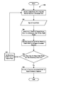
- FIG. 3 is a flowchart of a method 300 , in accordance with an example embodiment.
- method 300 may provide an embodiment for displaying child nodes of a designated node.
- the method begins at 302 , with a computing device designating a node of a tree as a current node.
- the computing device may designate the root node of the tree as the current node.
- the computing device may designate a current node based on a direct or indirect selection by the user.
- the method 300 continues at 304 with the computing device removing all nodes from a first group of nodes.
- the first group of nodes may include nodes associated with a previously designated current node. As such, with the designation of the first node as the current node, nodes associated with the previously designated current node maybe removed.
- the computing device may then copy each child node of the new current node to the first group.
- the method continues at 308 with the computing device removing all nodes from a second group of nodes. Similar to the first group of nodes, the second group of nodes may include nodes associated with a previously designated current node, and as such, with the designation of the first node as the current node, nodes associated with the previously designated current node may be removed.
- the computing device may move a selection of nodes from the first group to the second group.
- the selection of nodes from the first group may be determined based on a frequency of speech inputs associated with nodes in the first group of nodes. For instance, referring back to FIG. 1 , the current node may be the Settings node, and the child nodes Wi-Fi, Airplane Mode, VPN, and Ringtone may have been copied to the first group of nodes. Among the child nodes, speech input data associated with the Wi-Fi and VPN nodes may have been the most commonly received speech inputs. As such, the child nodes Wi-Fi and VPN may be moved from the first group of nodes to the second group of nodes. As another possibility, nodes associated with less frequent speech inputs may be moved to the second group.
- the method continues at 312 with the computing device presenting the nodes in the second group.
- the nodes in the second group may be provided on a display for the user to view.
- the display may not have space to show each child node of the current node, and accordingly, the second group of nodes including a subset of the child nodes of the current node may be selected to be shown on the display. In other words, in this case, only the child nodes Wi-Fi and VPN may be provided on the display for the user to view.
- the computing device receives an arbitrary speech input. Similar to 204 of the method 200 , the computing device may receive arbitrary speech input data via a microphone of the computing device.
- a determination is made as to whether the arbitrary speech input corresponds to a speech input of a child node of the current node.
- the speech input may be associated with a node in the second group, the first group, or a node previously in (but now removed from) the first and second groups. For instance, a user may provide speech input associated with a child node in the second group, in response to being visually presented the child node in the second group.
- the user may provide speech input associated with a child node in the first group, which has not yet been presented, because the user knows that the particular child node is an option.
- the method 300 may proceed to 318 to determine whether that corresponding child node itself has any child nodes. If the corresponding child node has one or more child nodes, then the method 300 may proceed to 320 , where the computing device may designate the corresponding child node as the current node. Referring to the example above, if the arbitrary speech input includes “Wi-Fi,” the computing system will then determine whether the Wi-Fi node has child nodes. As shown, the Wi-Fi node does have children, and accordingly, the Wi-Fi node may be designated as the current node.
- the method 300 may then proceed back to 304 , and performs 304 - 318 until the associated child node does not have one or more child nodes.
- 304 - 318 may be performed until speech input corresponding to one of the level IV nodes in the Wi-Fi node family has been received.
- the method 300 may proceed to 322 to determine whether the first group of nodes include additional child nodes of the current node. If the first group of nodes does not include additional child nodes of the current node, the method 300 may proceed back to 314 to await another arbitrary speech input. As another possibility, certain nodes may be designated as “do not display” nodes (such as a “Back” node or “Cancel” node); if the first group includes only these do not display nodes, then method 300 may proceed again to 314 .
- the method 300 may proceed back to 308 to remove the nodes from second group of nodes, and at 310 , move a selection (or the remaining) child nodes of the current node in the first group of nodes to the second group of nodes.
- the Airplane Mode and Ringtone nodes may still be in the first group of nodes.
- the method 300 may proceed back to 308 where the Wi-Fi and VPN nodes in the second ground of nodes may be removed, and where in 310 , the Airplane Mode and Ringtone nodes may be moved to the second group.
- the method 300 may then proceed through 312 - 322 as appropriate. This may be the case when a user wishes to select Airplane Mode, but is not very familiar with the grammar, and therefore waits for the Airplane Mode option to be provided on the graphical display before providing the corresponding speech input.
- the example methods discussed previously may be implemented on a system, which may take the form of a wearable computer. Further, the example methods may be implemented on other devices, such as a mobile phone, among others.
- the example methods may take the form of instructions stored on a non-transitory computer readable medium. In this case, the stored instructions may be executable by at a processor to provide the functionality described.
- FIG. 4A illustrates a wearable computing system on which the example methods discussed above may be implemented, according to an example embodiment.
- the wearable computing system takes the form of a head-mounted device (HMD) 402 (which may also be referred to as a head-mounted display).
- HMD head-mounted device
- the head-mounted device 402 includes frame elements including lens-frames 404 and 406 and a center frame support 408 , lens elements 410 and 410 , and extending side-arms 414 and 416 .
- the center frame support 408 and the extending side-arms 414 and 416 are configured to secure the head-mounted device 402 to a user's face via a user's nose and ears, respectively.
- Each of the frame elements 404 , 406 , and 408 and the extending side-arms 414 and 416 may be formed of a solid structure of plastic and/or metal, or may be formed of a hollow structure of similar material so as to allow wiring and component interconnects to be internally routed through the head-mounted device 402 .
- Other materials may be possible as well.
- each of the lens elements 410 and 412 may be formed of any material that can suitably display a projected image or graphic.
- Each of the lens elements 410 and 412 may also be sufficiently transparent to allow a user to see through the lens element. Combining these two features of the lens elements may facilitate an augmented reality or heads-up display where the projected image or graphic is superimposed over a real-world view as perceived by the user through the lens elements.
- the extending side-arms 414 and 416 may each be projections that extend away from the lens-frames 404 and 406 , respectively, and may be positioned behind a user's ears to secure the head-mounted device 402 to the user.
- the extending side-arms 414 and 416 may further secure the head-mounted device 402 to the user by extending around a rear portion of the user's head.
- the HMD 402 may connect to or be affixed within a head-mounted helmet structure. Other possibilities exist as well.
- the HMD 402 may also include an on-board computing system 418 , a video camera 420 , a sensor 422 , and a finger-operable touch pad 424 .
- the on-board computing system 418 is shown to be positioned on the extending side-arm 414 of the head-mounted device 402 ; however, the on-board computing system 418 may be provided on other parts of the head-mounted device 402 or may be positioned remote from the head-mounted device 402 (e.g., the on-board computing system 418 could be wire- or wirelessly-connected to the head-mounted device 402 ).
- the on-board computing system 418 may include a processor and memory, for example.
- the on-board computing system 418 may be configured to receive and analyze data from the video camera 420 and the finger-operable touch pad 424 (and possibly from other sensory devices, user interfaces, or both) and generate images for output by the lens elements 410 and 412 .
- the video camera 420 is shown positioned on the extending side-arm 414 of the head-mounted device 402 ; however, the video camera 420 may be provided on other parts of the head-mounted device 402 .
- the video camera 420 may be configured to capture images at various resolutions or at different frame rates. Many video cameras with a small form-factor, such as those used in cell phones or webcams, for example, may be incorporated into an example of the HMD 402 .
- FIG. 4A illustrates one video camera 420
- more video cameras may be used, and each may be configured to capture the same view, or to capture different views.
- the video camera 420 may be forward facing to capture at least a portion of the real-world view perceived by the user. This forward facing image captured by the video camera 420 may then be used to generate an augmented reality where computer generated images appear to interact with the real-world view perceived by the user.
- the sensor 422 is shown on the extending side-arm 416 of the head-mounted device 402 ; however, the sensor 422 may be positioned on other parts of the head-mounted device 402 .
- the sensor 422 may include one or more of a gyroscope or an accelerometer, for example. Other sensing devices may be included within, or in addition to, the sensor 422 or other sensing functions may be performed by the sensor 422 .
- the finger-operable touch pad 424 is shown on the extending side-arm 414 of the head-mounted device 402 . However, the finger-operable touch pad 424 may be positioned on other parts of the head-mounted device 402 . Also, more than one finger-operable touch pad may be present on the head-mounted device 402 .
- the finger-operable touch pad 424 may be used by a user to input commands.
- the finger-operable touch pad 424 may sense at least one of a position and a movement of a finger via capacitive sensing, resistance sensing, or a surface acoustic wave process, among other possibilities.
- the finger-operable touch pad 424 may be capable of sensing finger movement in a direction parallel or planar to the pad surface, in a direction normal to the pad surface, or both, and may also be capable of sensing a level of pressure applied to the pad surface.
- the finger-operable touch pad 424 may be formed of one or more translucent or transparent insulating layers and one or more translucent or transparent conducting layers. Edges of the finger-operable touch pad 424 may be formed to have a raised, indented, or roughened surface, so as to provide tactile feedback to a user when the user's finger reaches the edge, or other area, of the finger-operable touch pad 424 . If more than one finger-operable touch pad is present, each finger-operable touch pad may be operated independently, and may provide a different function.
- FIG. 4B illustrates an alternate view of the wearable computing device illustrated in FIG. 4A .
- the lens elements 410 and 412 may act as display elements.
- the head-mounted device 402 may include a first projector 428 coupled to an inside surface of the extending side-arm 416 and configured to project a display 430 onto an inside surface of the lens element 412 .
- a second projector 432 may be coupled to an inside surface of the extending side-arm 414 and configured to project a display 434 onto an inside surface of the lens element 410 .
- the head-mounted device 402 may also include one or more sensors coupled to an inside surface of head-mounted device 402 .
- sensor 436 coupled to an inside surface of the extending side-arm 414
- sensor 438 coupled to an inside surface of the extending side-arm 416 .
- the one or more sensors could take the form of a still or video camera (such as a charge-coupled device or CCD), any of the forms discussed with reference to sensor 422 , and/or numerous other forms, without departing from the scope of the claims.
- the one or more sensors (perhaps in coordination with one or more other entities) may be configured to perform eye tracking, such as gaze-target tracking, etc.
- the lens elements 410 , 412 may act as a combiner in a light projection system and may include a coating that reflects the light projected onto them from the projectors 428 and 432 .
- a reflective coating may not be used (e.g., when the projectors 428 and 432 are scanning laser devices).
- the lens elements 410 and 412 themselves may include a transparent or semi-transparent matrix display such as an electroluminescent display or a liquid crystal display, one or more waveguides for delivering an image to the user's eyes, and/or or other optical elements capable of delivering an in focus near-to-eye image to the user, among other possibilities.
- a corresponding display driver may be disposed within the frame elements 404 , 406 for driving such a matrix display.
- a laser or LED source and scanning system could be used to draw a raster display directly onto the retina of one or more of the user's eyes. Other possibilities exist as well.
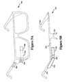
- FIG. 5A illustrates another wearable computing system on which the methods discussed above may be implemented, according to an example embodiment, which takes the form of an HMD 502 .
- the HMD 502 may include frame elements and side-arms such as those described with respect to FIGS. 4A and 4B .
- the HMD 502 may additionally include an on-board computing system 504 and a video camera 506 , such as those described with respect to FIGS. 4A and 4B .
- the video camera 506 is shown mounted on a frame of the HMD 502 . However, the video camera 506 may be mounted at other positions as well.
- the HMD 502 may include a single display 508 which may be coupled to the device.
- the display 508 may be formed on one of the lens elements of the HMD 502 , such as a lens element described with respect to FIGS. 4A and 4B , and may be configured to overlay computer-generated graphics in the user's view of the physical world.
- the display 508 is shown to be provided in a center of a lens of the HMD 502 , however, the display 508 may be provided in other positions.
- the display 508 is controllable via the computing system 504 that is coupled to the display 508 via an optical waveguide 510 .
- FIG. 5B illustrates another wearable computing system according to an example embodiment, which takes the form of an HMD 522 .
- the HMD 522 may include side-arms 523 , a center frame support 524 , and a bridge portion with nosepiece 525 .
- the center frame support 524 connects the side-arms 523 .
- the HMD 522 does not include lens-frames containing lens elements.
- the HMD 522 may additionally include an on-board computing system 526 and a video camera 528 , such as those described with respect to FIGS. 4A and 4B .
- the HMD 522 may include a single lens element 530 that may be coupled to one of the side-arms 523 or the center frame support 524 .
- the lens element 530 may include a display such as the display described with reference to FIGS. 4A and 4B , and may be configured to overlay computer-generated graphics upon the user's view of the physical world.
- the single lens element 530 may be coupled to the inner side (i.e., the side exposed to a portion of a user's head when worn by the user) of the extending side-arm 523 .
- the single lens element 530 may be positioned in front of or proximate to a user's eye when the HMD 522 is worn by a user.
- the single lens element 530 may be positioned below the center frame support 524 , as shown in FIG. 5B .
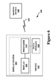
- FIG. 6 illustrates a schematic drawing of a computing device on which the methods described above may be implemented, according to an example embodiment.
- a device 610 communicates using a communication link 620 (e.g., a wired or wireless connection) to a remote device 630 .
- the device 610 may be any type of device that can receive data and display information corresponding to or associated with the data.
- the device 610 may be a heads-up display system, such as the head-mounted devices 402 , 502 , or 522 described with reference to FIGS. 4A , 4 B, 5 A, and 5 B.
- the device 610 may include a display system 612 comprising a processor 614 and a display 616 .
- the display 616 may be, for example, an optical see-through display, an optical see-around display, or a video see-through display.
- the processor 614 may receive data from the remote device 630 , and configure the data for display on the display 616 .
- the processor 614 may be any type of processor, such as a micro-processor or a digital signal processor, for example.
- the device 610 may further include on-board data storage, such as memory data storage 618 coupled to the processor 614 .
- the data storage 618 may store software and/or other instructions that can be accessed and executed by the processor 614 , for example.
- the remote device 630 may be any type of computing device or transmitter including a laptop computer, a mobile telephone, or tablet computing device, etc., that is configured to transmit data to the device 610 .
- the remote device 630 and the device 610 may contain hardware to enable the communication link 620 , such as processors, transmitters, receivers, antennas, etc.
- the communication link 620 is illustrated as a wireless connection; however, wired connections may also be used.
- the communication link 620 may be a wired serial bus such as a universal serial bus or a parallel bus.
- a wired connection may be a proprietary connection as well.
- the communication link 620 may also be a wireless connection using, e.g., Bluetooth® radio technology, communication protocols described in IEEE 802.11 (including any IEEE 802.11 revisions), Cellular technology (such as GSM, CDMA, UMTS, EV-DO, WiMAX, or LTE), or Zigbee® technology, among other possibilities.
- the remote device 630 may be accessible via the Internet and may include a computing cluster associated with a particular web service (e.g., social-networking, photo sharing, address book, etc.).
Abstract
Description
Claims (20)
Priority Applications (1)
| Application Number | Priority Date | Filing Date | Title |
|---|---|---|---|
| US13/625,120 US8856006B1 (en) | 2012-01-06 | 2012-09-24 | Assisted speech input |
Applications Claiming Priority (2)
| Application Number | Priority Date | Filing Date | Title |
|---|---|---|---|
| US201261584135P | 2012-01-06 | 2012-01-06 | |
| US13/625,120 US8856006B1 (en) | 2012-01-06 | 2012-09-24 | Assisted speech input |
Publications (1)
| Publication Number | Publication Date |
|---|---|
| US8856006B1 true US8856006B1 (en) | 2014-10-07 |
Family
ID=51627052
Family Applications (1)
| Application Number | Title | Priority Date | Filing Date |
|---|---|---|---|
| US13/625,120 Expired - Fee Related US8856006B1 (en) | 2012-01-06 | 2012-09-24 | Assisted speech input |
Country Status (1)
| Country | Link |
|---|---|
| US (1) | US8856006B1 (en) |
Cited By (4)
| Publication number | Priority date | Publication date | Assignee | Title |
|---|---|---|---|---|
| US9495357B1 (en) * | 2013-05-02 | 2016-11-15 | Athena Ann Smyros | Text extraction |
| CN110134466A (en) * | 2018-02-02 | 2019-08-16 | 北京三星通信技术研究有限公司 | Information processing method and terminal device |
| US10826783B2 (en) * | 2016-04-20 | 2020-11-03 | Servicenow, Inc. | System and method for custom graph generation |
| US11398234B2 (en) * | 2020-03-06 | 2022-07-26 | Hitachi, Ltd. | Utterance support apparatus, utterance support method, and recording medium |
Citations (7)
| Publication number | Priority date | Publication date | Assignee | Title |
|---|---|---|---|---|
| US5323316A (en) * | 1991-02-01 | 1994-06-21 | Wang Laboratories, Inc. | Morphological analyzer |
| US20040181414A1 (en) | 2003-03-11 | 2004-09-16 | Pyle Michael W. | Navigated menuing for industrial human machine interface via speech recognition |
| US6965863B1 (en) | 1998-11-12 | 2005-11-15 | Microsoft Corporation | Speech recognition user interface |
| US20050256891A1 (en) * | 2004-05-10 | 2005-11-17 | Mr. Igor Voln | A code or data representation and manipulation system that allows user to view, modify, and manipulate structured entities, such as code or data files, using their tree-like representations. |
| US20060218506A1 (en) | 2005-03-23 | 2006-09-28 | Edward Srenger | Adaptive menu for a user interface |
| US20100324888A1 (en) * | 2007-12-27 | 2010-12-23 | Assaf Rachamim | Solving constraint satisfaction problems for user interface and search engine |
| US8005679B2 (en) | 2001-10-03 | 2011-08-23 | Promptu Systems Corporation | Global speech user interface |
-
2012
- 2012-09-24 US US13/625,120 patent/US8856006B1/en not_active Expired - Fee Related
Patent Citations (7)
| Publication number | Priority date | Publication date | Assignee | Title |
|---|---|---|---|---|
| US5323316A (en) * | 1991-02-01 | 1994-06-21 | Wang Laboratories, Inc. | Morphological analyzer |
| US6965863B1 (en) | 1998-11-12 | 2005-11-15 | Microsoft Corporation | Speech recognition user interface |
| US8005679B2 (en) | 2001-10-03 | 2011-08-23 | Promptu Systems Corporation | Global speech user interface |
| US20040181414A1 (en) | 2003-03-11 | 2004-09-16 | Pyle Michael W. | Navigated menuing for industrial human machine interface via speech recognition |
| US20050256891A1 (en) * | 2004-05-10 | 2005-11-17 | Mr. Igor Voln | A code or data representation and manipulation system that allows user to view, modify, and manipulate structured entities, such as code or data files, using their tree-like representations. |
| US20060218506A1 (en) | 2005-03-23 | 2006-09-28 | Edward Srenger | Adaptive menu for a user interface |
| US20100324888A1 (en) * | 2007-12-27 | 2010-12-23 | Assaf Rachamim | Solving constraint satisfaction problems for user interface and search engine |
Cited By (5)
| Publication number | Priority date | Publication date | Assignee | Title |
|---|---|---|---|---|
| US9495357B1 (en) * | 2013-05-02 | 2016-11-15 | Athena Ann Smyros | Text extraction |
| US9772991B2 (en) | 2013-05-02 | 2017-09-26 | Intelligent Language, LLC | Text extraction |
| US10826783B2 (en) * | 2016-04-20 | 2020-11-03 | Servicenow, Inc. | System and method for custom graph generation |
| CN110134466A (en) * | 2018-02-02 | 2019-08-16 | 北京三星通信技术研究有限公司 | Information processing method and terminal device |
| US11398234B2 (en) * | 2020-03-06 | 2022-07-26 | Hitachi, Ltd. | Utterance support apparatus, utterance support method, and recording medium |
Similar Documents
| Publication | Publication Date | Title |
|---|---|---|
| JP7200195B2 (en) | sensory eyewear | |
| US10319382B2 (en) | Multi-level voice menu | |
| US20230120601A1 (en) | Multi-mode guard for voice commands | |
| US8217856B1 (en) | Head-mounted display that displays a visual representation of physical interaction with an input interface located outside of the field of view | |
| US8519909B2 (en) | Multimode input field for a head-mounted display | |
| US10289205B1 (en) | Behind the ear gesture control for a head mountable device | |
| US9798517B2 (en) | Tap to initiate a next action for user requests | |
| US9666187B1 (en) | Model for enabling service providers to address voice-activated commands | |
| US9064436B1 (en) | Text input on touch sensitive interface | |
| US20130021269A1 (en) | Dynamic Control of an Active Input Region of a User Interface | |
| US9368113B2 (en) | Voice activated features on multi-level voice menu | |
| US10303435B2 (en) | Head-mounted display device, method of controlling head-mounted display device, and computer program | |
| US9607440B1 (en) | Composite image associated with a head-mountable device | |
| US9500867B2 (en) | Head-tracking based selection technique for head mounted displays (HMD) | |
| US9336779B1 (en) | Dynamic image-based voice entry of unlock sequence | |
| US20150138073A1 (en) | Text Selection Using HMD Head-Tracker and Voice-Command | |
| US20170115736A1 (en) | Photo-Based Unlock Patterns | |
| US8856006B1 (en) | Assisted speech input | |
| US9316830B1 (en) | User interface | |
| US20170139567A1 (en) | Entering Unlock Sequences Using Head Movements | |
| US9305064B1 (en) | Keyword-based conversational searching using voice commands | |
| KR20240009984A (en) | Contextual visual and voice search from electronic eyewear devices | |
| US20190179525A1 (en) | Resolution of Directional Ambiguity on Touch-Based Interface Based on Wake-Up Gesture | |
| US20150054747A1 (en) | Circular Keyboard | |
| EP4281854A1 (en) | Digital assistant interactions in extended reality |
Legal Events
| Date | Code | Title | Description |
|---|---|---|---|
| STCF | Information on status: patent grant |
Free format text: PATENTED CASE |
|
| AS | Assignment |
Owner name: GOOGLE INC., CALIFORNIA Free format text: ASSIGNMENT OF ASSIGNORS INTEREST;ASSIGNORS:STARNER, THAD EUGENE;PATEL, NIRMAL;BALEZ, MAT;SIGNING DATES FROM 20120106 TO 20120913;REEL/FRAME:043532/0379 |
|
| AS | Assignment |
Owner name: GOOGLE LLC, CALIFORNIA Free format text: CHANGE OF NAME;ASSIGNOR:GOOGLE INC.;REEL/FRAME:044277/0001 Effective date: 20170929 |
|
| MAFP | Maintenance fee payment |
Free format text: PAYMENT OF MAINTENANCE FEE, 4TH YEAR, LARGE ENTITY (ORIGINAL EVENT CODE: M1551) Year of fee payment: 4 |
|
| FEPP | Fee payment procedure |
Free format text: MAINTENANCE FEE REMINDER MAILED (ORIGINAL EVENT CODE: REM.); ENTITY STATUS OF PATENT OWNER: LARGE ENTITY |
|
| LAPS | Lapse for failure to pay maintenance fees |
Free format text: PATENT EXPIRED FOR FAILURE TO PAY MAINTENANCE FEES (ORIGINAL EVENT CODE: EXP.); ENTITY STATUS OF PATENT OWNER: LARGE ENTITY |
|
| STCH | Information on status: patent discontinuation |
Free format text: PATENT EXPIRED DUE TO NONPAYMENT OF MAINTENANCE FEES UNDER 37 CFR 1.362 |
|
| FP | Lapsed due to failure to pay maintenance fee |
Effective date: 20221007 |