US8855040B1 - Cross-cell MIMO - Google Patents
Cross-cell MIMO Download PDFInfo
- Publication number
- US8855040B1 US8855040B1 US12/244,376 US24437608A US8855040B1 US 8855040 B1 US8855040 B1 US 8855040B1 US 24437608 A US24437608 A US 24437608A US 8855040 B1 US8855040 B1 US 8855040B1
- Authority
- US
- United States
- Prior art keywords
- base station
- data
- communications information
- receiving device
- communications
- Prior art date
- Legal status (The legal status is an assumption and is not a legal conclusion. Google has not performed a legal analysis and makes no representation as to the accuracy of the status listed.)
- Expired - Fee Related, expires
Links
Images


Classifications
-
- H—ELECTRICITY
- H04—ELECTRIC COMMUNICATION TECHNIQUE
- H04B—TRANSMISSION
- H04B15/00—Suppression or limitation of noise or interference
-
- H—ELECTRICITY
- H04—ELECTRIC COMMUNICATION TECHNIQUE
- H04J—MULTIPLEX COMMUNICATION
- H04J11/00—Orthogonal multiplex systems, e.g. using WALSH codes
- H04J11/0023—Interference mitigation or co-ordination
- H04J11/005—Interference mitigation or co-ordination of intercell interference
-
- H—ELECTRICITY
- H04—ELECTRIC COMMUNICATION TECHNIQUE
- H04B—TRANSMISSION
- H04B7/00—Radio transmission systems, i.e. using radiation field
- H04B7/02—Diversity systems; Multi-antenna system, i.e. transmission or reception using multiple antennas
- H04B7/04—Diversity systems; Multi-antenna system, i.e. transmission or reception using multiple antennas using two or more spaced independent antennas
- H04B7/0413—MIMO systems
-
- H—ELECTRICITY
- H04—ELECTRIC COMMUNICATION TECHNIQUE
- H04B—TRANSMISSION
- H04B1/00—Details of transmission systems, not covered by a single one of groups H04B3/00 - H04B13/00; Details of transmission systems not characterised by the medium used for transmission
-
- H—ELECTRICITY
- H04—ELECTRIC COMMUNICATION TECHNIQUE
- H04B—TRANSMISSION
- H04B17/00—Monitoring; Testing
-
- H—ELECTRICITY
- H04—ELECTRIC COMMUNICATION TECHNIQUE
- H04B—TRANSMISSION
- H04B7/00—Radio transmission systems, i.e. using radiation field
- H04B7/02—Diversity systems; Multi-antenna system, i.e. transmission or reception using multiple antennas
- H04B7/022—Site diversity; Macro-diversity
- H04B7/024—Co-operative use of antennas of several sites, e.g. in co-ordinated multipoint or co-operative multiple-input multiple-output [MIMO] systems
-
- H—ELECTRICITY
- H04—ELECTRIC COMMUNICATION TECHNIQUE
- H04W—WIRELESS COMMUNICATION NETWORKS
- H04W72/00—Local resource management
-
- H—ELECTRICITY
- H04—ELECTRIC COMMUNICATION TECHNIQUE
- H04W—WIRELESS COMMUNICATION NETWORKS
- H04W72/00—Local resource management
- H04W72/50—Allocation or scheduling criteria for wireless resources
- H04W72/54—Allocation or scheduling criteria for wireless resources based on quality criteria
Definitions
- This document relates to interference reduction in communication signals.
- This aspect of spectrum utilization also provides for uncoordinated band allocation in which a signal in the band appears as noise in relation to other signals in the band. Such uncoordinated band allocation results in optimal cumulative spectrum utilization.
- Utilization can be increased using Multiple-Input, Multiple-Output (MIMO), which uses multiple antennas at both the transmitter and receiver to improve communication performance.
- MIMO increases spectrum capacity in accordance with the number of transmit antennas and receive antennas above what could otherwise have been achieved because the number of independent channels available in a given spectrum band is increased.
- a wireless device may often receive communications from two or more base stations, e.g., cellular towers. Receiving such multiple communications can cause interference and degrade signal quality.
- one aspect of the subject matter described in this document can be implemented in methods that include the actions of receiving first communications information from a first base station at a second base station and generating second communications information for transmission to the receiving device.
- the first communications information identifies data for transmission over a channel from the first base station to a receiving device.
- the second communications information comprises data for transmission from the second base station to the receiving device to reduce interference with the first communications information.
- Another aspect of the subject matter described in this document can be implemented in methods that include the actions of identifying a wireless device, determining whether the wireless device is an interference source, and transmitting communications information to one or more base stations, wherein the communications information includes the data sent to the wireless device.
- Other embodiments of this aspect include corresponding systems, apparatus, and computer program products.
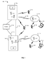
- FIG. 1 is a block diagram of an example communications network for utilizing electromagnetic spectrum.
- FIG. 2 is a diagram illustrating an example MIMO coordination that can be implemented in the communications network.
- FIG. 3 is a block diagram of another example communications network.
- FIG. 4 is a flow chart illustrating an example method for canceling interference from base stations.
- FIG. 5 is a flow chart illustrating an example method for providing interference information to base stations.
- This document relates to MIMO techniques that can be performed across different communications cells (“cells”) in a wireless network.
- Wireless devices that are located near the border of a cell may receive transmissions from some or all of the base stations that define the neighboring cells. The presence of the transmissions from the neighboring cells can cause interference with the transmissions of the other cells that are communicating with the wireless device. This interference can cause each of the base stations to increase its power output in an attempt to overcome the interference.
- neighboring base stations are aware of the transmissions that are being sent to the wireless device, this information can be used to coordinate the transmissions of neighboring base stations to a wireless device.
- the base stations of a wireless network can be characterized as individual antennas of a MIMO communications system. Accordingly, MIMO communications techniques (e.g., successive interference cancellation) can be used across the cells of the wireless network to reduce the interference from neighboring base stations and coordinate transmissions from the base stations to the wireless device. For example, a base station can provide a neighboring base station with the data that it is transmitting to a particular wireless device. In turn, the neighboring base station can adjust its transmission to the wireless device to reduce the interference experienced by the particular wireless device base station.
- MIMO communications techniques e.g., successive interference cancellation
- FIG. 1 is a block diagram of a communications network 100 for utilizing electromagnetic spectrum.
- one or more base stations 110 a and 110 b can be provided.
- the base stations 110 a and 110 b can include access points 112 using a predetermined portion of the electromagnetic spectrum.
- the access points 112 can be arranged as a Multiple-In, Multiple-Out (MIMO) antenna array, which uses multiple antennas at the transmitter and receiver.
- MIMO Multiple-In, Multiple-Out
- the access points 112 can communicate in the 500 MHz-700 MHz spectrum.
- MIMO technology increases the data throughput and link range through higher spectral efficiency and link diversity.
- MIMO systems transmit a data stream on each of the transmit antennas, which increases the overall bandwidth of the system.
- the data streams associated with a particular antenna are intended for a corresponding receiver antenna.
- the communications link between the transmitter and the intended receiver is a channel of the MIMO system.
- data streams transmitted over a channel are also received by the other receiver antennas over different transmission paths.
- the transmitted data streams intended for a particular antenna can interfere with communications intended for the other receiver antennas. Therefore, interference cancellation techniques are implemented to reduce the effects of the interference and maintain link diversity.
- each of the access points 112 can communicate with a wireless device 122 over a wireless link 118 as part of a MIMO array.
- each access point 112 can be a transmit antenna in the MIMO array while each wireless device 122 can be a receive antenna in the MIMO array.
- an access point 112 can transmit data that are intended for a particular wireless device 122 over a channel (e.g., a link between corresponding antennas) in the MIMO array.
- While the transmitted data can be received by the particular wireless device, it can also be received by other wireless devices that are within the range of the access point 112 .
- the data transmitted on one channel may interfere with the data transmitted on other channels. Therefore, interference cancellation techniques can be used to cancel the interference from an access point that is transmitting data intended for another wireless device.
- the wireless devices 122 are the transmit antennas of the MIMO array and the access points are the receive antennas.
- the transmissions from the wireless devices can similarly cause interference on other channels in the MIMO array. Therefore, interference cancellation techniques can be implemented in an access point 112 to cancel interference from a wireless device 122 that is transmitting data intended for another access point.
- multiple base stations 110 a and 110 b can communicate with each other over a back-link 121 .
- the back-link 121 can be, for example, a dedicated fiber-optic link.
- the back-link 121 can be, for example, a connection that is created over the Internet.
- the base stations 110 a and 110 b can transmit communications information to each other over the back-link 121 .
- a first base station 110 a can send information to a second base station 110 b identifying the data for transmission from the first base station to wireless devices 122 .
- the second base station 110 b can send similar information to the first base station.
- the base stations 110 a and 110 b can use the received communications information to implement interference cancellation techniques to cancel interference that a wireless device experiences due to transmissions from the other base station 110 b , 110 a .
- the antennas of base stations 110 a and 110 b can be treated as antennas in a MIMO array.
- the base stations 110 a and 110 b can communicate to a service provider 120 using a fixed communications link, for example, a wide area network, a fiber optic link, a satellite link, or other available link.
- a fixed communications link for example, a wide area network, a fiber optic link, a satellite link, or other available link.
- one or more repeaters 114 can be provided. Each repeater 114 can have one or more access points 112 operating similarly as in the base stations 110 a and 110 b to improve the range of a communications network 121 .
- the repeaters 114 can be located in a mobile environment (e.g., in a vehicle). In other implementations, the repeaters 114 can be located in a fixed environment (e.g., a building, a residential dwelling, a utility pole).
- Wireless devices 122 can communicate to the base stations 110 a and 110 b or the repeaters 114 to access services provided by a provider 120 .
- the repeaters 114 , wireless devices 122 and base stations 110 a and 110 b can communicate with each other using wireless links 118 .
- a combination of wireless links 118 and fixed links e.g., wire, fiber
- the repeaters 114 can be spatially arranged according to the propagation characteristics of the spectrum in use, which in the case of the broadcast television spectrum can be approximately 10 km apart.
- the repeaters 114 and wireless devices 122 can communicate, for example, at 100 mW in the mobile environments and 1 W in fixed environments. Other communication specifications can also be used.
- Ultra-Wide-Band (UWB) communications can be performed between the base stations 110 a and 110 b , repeaters 114 and wireless devices 122 using direct sequence spread spectrum (DSSS), which more nearly approaches the information theoretic ideal of representing a signal by white noise.
- DSSS direct sequence spread spectrum
- narrow-band communications can be performed between the base stations 110 a and 110 b , repeaters 114 and wireless devices 122 .
- a wireless device 122 a can be in communication with two or more base stations 110 a , 110 b .
- the communications between the wireless device 122 a and each of the base stations 110 a , 110 b may be characterized as interference by the other base station 110 b , 110 a .
- this interference can be reduced by characterizing the base stations 110 a , 110 b as antennas in a MIMO communications system.
- each base station 110 a , 110 b can provide the data being sent to the wireless device 122 a to the other base station 110 b , 110 a .
- the base stations 110 a , 110 b can coordinate communications to the wireless device 122 a so that the interference is reduced.
- the base stations 110 a and 110 b can include one or more interference cancellation engines 124 .
- the interference cancellation engines 124 are configured to cancel interference experienced by the wireless devices 122 using MIMO communications techniques, as will be discussed below.
- the interference cancellation engines 124 can be implemented in software that runs on a data processing apparatus, or can be implemented entirely in a special purpose data processing apparatus, e.g., application specific integrated circuits (ASICS), field programmable gate arrays (FPGAs), etc. Other software and/or hardware implementations can also be used.
- ASICS application specific integrated circuits
- FPGAs field programmable gate arrays
- FIG. 2 is a diagram illustrating an example MIMO coordination that can be implemented in the communications network 100 .
- each antenna associated with the base station 110 transmits communications on different channels.
- each antenna associated with the wireless device 122 receives the transmission from a corresponding antenna at the base station 110 .
- the channel hnn-d represents the transmission from antenna n at the base station 110 to antenna n at the wireless device 122 .
- the communications transmission on channel hnn-d is subject to interference from the data transmitted by the antennas 1 to n ⁇ 1 of the base station 110 .
- the interference from communications transmitted on antennas 1 to n ⁇ 1 can be identified and compensated for in the communications that are received at antenna n.
- the interference from the antennas 1 to n ⁇ 1 associated with the wireless devices 122 can also be identified and compensated for, to accurately recover the communications transmitted on channel hnn-u.
- a channel interference cancellation technique can be used to compensate for the interference from data transmitted on separate channels of the MIMO system.
- the channel interference cancellation technique can be implemented, for example, in the interference cancellation engine 124 .
- the interference cancellation engine 124 can facilitate interference cancellation in a MIMO system implementing spatial multiplexing by subtracting known channel interferers from a select channel transmission.
- Spatial multiplexing and interference subtraction can be implemented to provide, for example, the following channel capacity for M ⁇ N MIMO (M transmitters, N receivers) with a given bandwidth and signal to noise ration (SNR):
- the channel interference cancellation can be performed on either the transmit side or the receive side, e.g., precoding for the “broadcast channel” downlink (DL) 202 , and decoding for the “multiple access channel” uplink (UL) 204 .
- the precoding and decoding can be performed to reduce interference that a wireless device experiences due to transmissions from other nearby base stations (e.g., across cells) by considering the base stations as antennas in a MIMO array.
- the data needed to perform the interference cancellation across cells can be received, for example, over a back-link between the base stations, e.g. the first base station 110 a and the second base station 110 b .
- the precoding and decoding can be performed, for example, according to the following equations:
- Providing channel interference cancellation in the base station 110 enables a group of wireless devices 122 (e.g., client nodes) that are associated with a select base station to be treated as an array, even without any explicit communication between the wireless devices 122 . This is because the base station 110 controls all of the data transmitted on the antennas within the base station 110 . Therefore, the base station 110 can identify the interferers from the other antennas and cancel the interference that a select wireless device 122 is experiencing due to transmissions from the other antennas.
- wireless devices 122 e.g., client nodes
- the base station 110 can identify the communications received from each of the wireless devices 122 . In turn, the base station 110 can remove the interference on the select channel that is caused by the wireless devices 122 operating on the other channels. Accordingly, the interference experienced on the select channel from other channels can be subtracted from the communications that are being sent to a select wireless device. While an example channel interference cancellation technique distributed across bases stations 110 a and 110 b is provided, other channel interference cancellation techniques distributed across two or more base stations can also be used (e.g., successive interference cancellation for a MIMO system).
- FIG. 3 is a block diagram illustrating another example communications network 300 .
- the communications network 300 can include multiple base stations.
- the base stations can communicate with wireless devices.
- the wireless devices can be mobile nodes 122 b , 122 d , 122 a (e.g., smart devices, laptop computers, etc).
- the wireless devices can be stationary nodes 122 c (e.g., desktop computers, repeaters, etc).
- Each base station has a defined region within which the base station can communicate with the wireless devices.
- base station A 110 a has a defined region 302 within which it can communicate with wireless devices 122 b - d .
- base station B 110 b has a defined region 304 within which it can communicate with wireless devices 122 a , 122 c and 122 d .
- the defined regions 302 , 304 are determined in part by a combination of the electrical characteristics of the base stations and wireless devices as well as the environmental conditions and regulations.
- wireless devices can be located in more than one defined region at the same time.
- wireless devices 122 c , 122 d are located within both defined regions 302 , 304 . Accordingly, both base station A 110 a and base station B 110 b can communicate with wireless devices 122 c , 122 d . However, as each base station 110 a and 110 b attempts to communicate with the wireless devices 122 c , 122 d , both base stations 110 a and 110 b may continue to increase their respective power output to compensate for interference. This power increase can continue until each base station 110 a and 110 b is transmitting at maximum power.
- each of the base stations 110 a and 110 b increases its power it creates more interference with the communications from the other base station 110 a and 110 b , potentially resulting in neither base station 110 a and 110 b being able to communicate with the wireless devices 122 c , 122 d.
- communications can be coordinated among the base stations and the interference from neighboring base stations can be cancelled when a wireless device is between base stations.
- This coordination and interference cancellation can be accomplished, for example, by treating each base station as part of a MIMO array and performing a channel interference cancellation technique across multiple base stations.
- the coordination between neighboring base stations can be defined, for example, according to a signal to interference plus noise (SINR) analysis that determines whether a base station should increase its power or reduce interference from the neighboring base station.
- SINR signal to interference plus noise
- a SINR optimization can be performed by the base stations, for example, according to the following SINR optimization formula:
- the optimization can take place based on a power constraint (K).
- the base stations can determine whether to increase their transmission power or reduce interference, for example, according to the following rules:
- the base station will maximize SINR by allocating as much power as possible to increasing the signal power.
- the base station will maximize SINR by allocating as much power as possible to reducing the interference power.
- the SINR optimization routine when the power constraint is less than a threshold (e.g., the sum of noise and interference), power will be allocated to strengthen the signal transmitted by the base station. In contrast, when the power constraint is greater than the threshold, all of the available power will be allocated to reduce the interference from the neighboring base station.
- a threshold e.g., the sum of noise and interference
- all of the available power will be allocated to reduce the interference from the neighboring base station.
- the select base station can identify the data that are being received by the wireless device from the other base stations.
- the select base station can identify the data by receiving communications information from the other base stations.
- the communications information can be received over a network connection between the select base station and the other base stations.
- the network connection can be, for example, a dedicated OC-192 fiber back-link.
- other back-links can be used (e.g., wide area network, local area network, the Internet, RF communications, etc.).
- a neighboring base station When a neighboring base station receives a pilot signal from a new wireless device that is not part of its communications network, it may identify the wireless device as an interference source. In response, the neighboring node can send communications information to the select node that will enable the select node to cancel the interference from the neighboring node when the select node communicates with the wireless device.
- base station A 110 a can transmit a transfer function (H a ) to the wireless device 122 d .
- the transfer function (H a ) is derived from the pilot signal and data (D a ) that base station A 110 a sends in the back-link to base station B 110 b .
- base station B 110 b reduces the interference that is experienced by wireless device 122 d due to the transmission of base station A 110 a .
- Base station B 110 b reduces the interference by subtracting the data associated with base station A 110 a from the data (D b ) that it transmits to the wireless device 122 d (e.g., D b ⁇ H a *D a ).
- a bandwidth optimization determination can be performed, for example, to identify the minimum back-link bandwidth required to deliver data from the neighboring base stations to the select base station prior to transmission of data to the wireless devices by the select base station. For example, in some implementations, bandwidth is minimized when the following are true:
- Notation Meaning Units M Number of symbols in the NA uplink N Number of symbols in the NA downlink A i Data generated in symbol i Bit/second H i Transfer Function Bit/second generated in symbol i I i Node ID generated in Bit/second symbol i N s Number of “interference NA sources” considered D i Total data generated in Bit symbol i F i (t) Amount of data generated Bit in symbol i and transmitted in symbol t c(t) Backlink capacity at Bit/second symbol t T p Process Time Second T g Propagation Delay Second T s Symbol Time Second N d Mind distance between NA uplink and downlink for a client in dynamic scheduling BW Upper bound of the link Bit/second capacity
- the data from the neighboring base station will arrive before the select base station sends data to the wireless device in the downlink.
- the base station can alternatively send interference data to its neighbors as soon as it decodes the pilots and then continue to send interference data sequentially.
- the back-link capacity can be treated as fixed so that the data generated in each symbol is substantially constant.
- base stations can identify wireless devices that are proximate to a communications border and transmit only the data required to cancel the interference experienced by these wireless devices. For example, in FIG. 3 base station A 110 a could send the information required for base station B 110 b to cancel the interference from base station A 110 a experienced by all wireless devices 122 a , 122 c , 122 d within the defined region 304 .
- the wireless device 122 a that is only in defined region 304 will not experience the same level of interference from base station A 110 a as the wireless devices 122 c , 122 d that are in both defined regions 302 , 304 . Therefore, base station A 110 a can elect to send only the data needed to cancel the interference experienced by wireless devices 122 c , 122 d that are in both defined regions 302 , 304 . This reduces the amount of data that base station A 110 a is required to send and, in turn, also reduces the minimum bandwidth required in the back-link.
- the base station can identify the locations of the wireless devices. For example, base stations can use triangulation to determine the location of the wireless device. Alternatively, base stations can use global positioning satellite (GPS) information to identify the location of wireless devices that are equipped with GPS transmitters. Other wireless device location methods can also be used (e.g., received signal strength indicators). The base station can determine whether the wireless device is near a communications border by comparing the location of the wireless device to information that characterizes the communications borders.
- GPS global positioning satellite
- the base stations are provided information that characterizes the communications borders (e.g., identifies proximate base stations). For example, if a single service provider installs the select node and all of the proximate communication nodes then the service provider can provide information about the proximate nodes to the select node to enable communications between the nodes.
- the base stations may be required to identify proximate base stations on an ad hoc basis. This situation can arise, for example, when different entities (e.g., service providers) install independent base stations in a particular area and do not provide information about their base stations.
- the base stations can identify proximate base stations by detecting pilot signals from the proximate base stations. Based on the information contained in the pilot signal, the base stations can successfully exchange communications information with the proximate base stations.
- FIG. 4 is a flow chart illustrating an example method 400 for canceling interference across communications cells.
- the method 400 can optionally identify a base station that is communicating over a communications channel ( 402 ).
- the base station can be identified, for example, by a select base station that does not have information identifying base stations that are communicating over the one or more channels. Accordingly, the base station may determine the proximate base stations that are proximately located on an ad hoc basis.
- the base stations can be identified, for example, by detecting pilot signals associated with the base stations.
- the method 400 receives first communications information from a first base station at a second base station ( 404 ).
- the communications can be received, for example, over a fiber-optic back-link that connects the first base station and the second base station.
- the first communications information can identify data for transmission over a channel from the first base station to a receiving device.
- the first communications information can also include a transfer function associated with the data.
- the communications can be communications on a select channel in a MIMO communications system.
- the communications can be received, for example, by a select base station that is communicating with a select wireless device.
- the method 400 continues by generating second communications information for transmission to the receiving device from the second base station ( 406 ).
- the second communications information can be data that reduces interference with the first communications information.
- the interference can be reduced by subtracting the product of the data and the transfer function from the data for transmission by the second base station.
- FIG. 5 is a flow chart illustrating an example method 500 for providing interference information to base stations.
- the method 500 begins by identifying a wireless device ( 502 ).
- the wireless device can be identified for example by a base station that is part of a communications network.
- the wireless device is identified in response to receiving a pilot signal from the wireless device.
- the method 500 continues by determining whether the wireless device is an interference source ( 504 ).
- the wireless device can be identified as an interference source, for example, by determining if the wireless device is receiving communications from other base stations.
- the wireless device can be determined to be receiving communications from other base stations based on its location. For example, if the wireless device is proximate to a communications border, then it will likely be receiving communications from other base stations in the communications network.
- the method 500 continues by transmitting communications information to one or more base stations ( 506 ).
- the communications information can contain the data for transmission to the wireless device as well as a transfer function associated with the data that are sent to the wireless device.
- the one or more base stations can be nodes that are proximately located to the base station.
- Embodiments of the subject matter and the functional operations described in this specification can be implemented in digital electronic circuitry, or in computer software, firmware, or hardware, including the structures disclosed in this specification and their structural equivalents, or in combinations of one or more of them.
- Embodiments of the subject matter described in this specification can be implemented as one or more computer program products, i.e., one or more modules of computer program instructions encoded on a tangible program carrier for execution by, or to control the operation of, data processing apparatus.
- the tangible program carrier can be a propagated signal or a computer-readable medium.
- the propagated signal is an artificially generated signal, e.g., a machine-generated electrical, optical, or electromagnetic signal that is generated to encode information for transmission to suitable receiver apparatus for execution by a computer.
- the computer-readable medium can be a machine-readable storage device, a machine-readable storage substrate, a memory device, a composition of matter effecting a machine-readable propagated signal, or a combination of one or more of them.
- data processing apparatus encompasses all apparatus, devices, and machines for processing data, including by way of example a programmable processor, a computer, or multiple processors or computers.
- the apparatus can include, in addition to hardware, code that creates an execution environment for the computer program in question, e.g., code that constitutes processor firmware, a protocol stack, a database management system, an operating system, or a combination of one or more of them.
- a computer program (also known as a program, software, software application, script, or code) can be written in any form of programming language, including compiled or interpreted languages, or declarative or procedural languages, and it can be deployed in any form, including as a stand-alone program or as a module, component, subroutine, or other unit suitable for use in a computing environment.
- a computer program does not necessarily correspond to a file in a file system.
- a program can be stored in a portion of a file that holds other programs or data (e.g., one or more scripts stored in a markup language document), in a single file dedicated to the program in question, or in multiple coordinated files (e.g., files that store one or more modules, sub-programs, or portions of code).
- a computer program can be deployed to be executed on one computer or on multiple computers that are located at one site or distributed across multiple sites and interconnected by a communication network.
- the processes and logic flows described in this specification can be performed by one or more programmable processors executing one or more computer programs to perform functions by operating on input data and generating output.
- the processes and logic flows can also be performed by, and apparatus can also be implemented as, special purpose logic circuitry, e.g., an FPGA (field programmable gate array) or an ASIC (application-specific integrated circuit).
- processors suitable for the execution of a computer program include, by way of example, both general and special purpose microprocessors, and any one or more processors of any kind of digital computer.
- a processor will receive instructions and data from a read-only memory or a random access memory or both.
- the essential elements of a computer are a processor for performing instructions and one or more memory devices for storing instructions and data.
- a computer will also include, or be operatively coupled to receive data from or transfer data to, or both, one or more mass storage devices for storing data, e.g., magnetic, magneto-optical disks, or optical disks.
- mass storage devices for storing data, e.g., magnetic, magneto-optical disks, or optical disks.
- a computer need not have such devices.
- a computer can be embedded in another device, e.g., a mobile telephone, a personal digital assistant (PDA), a mobile audio or video player, a game console, a Global Positioning System (GPS) receiver, to name just a few.
- PDA personal digital assistant
- GPS Global Positioning System
- Computer-readable media suitable for storing computer program instructions and data include all forms of non-volatile memory, media and memory devices, including by way of example semiconductor memory devices, e.g., EPROM, EEPROM, and flash memory devices; magnetic disks, e.g., internal hard disks or removable disks; magneto-optical disks; and CD-ROM and DVD-ROM disks.
- semiconductor memory devices e.g., EPROM, EEPROM, and flash memory devices
- magnetic disks e.g., internal hard disks or removable disks
- magneto-optical disks e.g., CD-ROM and DVD-ROM disks.
- the processor and the memory can be supplemented by, or incorporated in, special purpose logic circuitry.
- embodiments of the subject matter described in this specification can be implemented on a computer having a display device, e.g., a CRT (cathode ray tube) or LCD (liquid crystal display) monitor, for displaying information to the user and a keyboard and a pointing device, e.g., a mouse or a trackball, by which the user can provide input to the computer.
- a display device e.g., a CRT (cathode ray tube) or LCD (liquid crystal display) monitor
- keyboard and a pointing device e.g., a mouse or a trackball
- Other kinds of devices can be used to provide for interaction with a user as well; for example, feedback provided to the user can be any form of sensory feedback, e.g., visual feedback, auditory feedback, or tactile feedback; and input from the user can be received in any form, including acoustic, speech, or tactile input.
- Embodiments of the subject matter described in this specification can be implemented in a computing system that includes a back-end component, e.g., as a data server, or that includes a middleware component, e.g., an application server, or that includes a front-end component, e.g., a client computer having a graphical user interface or a Web browser through which a user can interact with an implementation of the subject matter described in this specification, or any combination of one or more such back-end, middleware, or front-end components.
- the components of the system can be interconnected by any form or medium of digital data communication, e.g., a communication network. Examples of communication networks include a local area network (“LAN”) and a wide area network (“WAN”), e.g., the Internet.
- LAN local area network
- WAN wide area network
- the computing system can include clients and servers.
- a client and server are generally remote from each other and typically interact through a communication network.
- the relationship of client and server arises by virtue of computer programs running on the respective computers and having a client-server relationship to each other.
Abstract
Description
| Notation | Meaning |
| T | Downlink channel output |
| X | Downlink channel input |
| h | Transfer matrix |
| R | Uplink channel input |
| Y | Uplink channel output |
| n | nth antenna |
| i | ith antenna |
K=P s +ΣP c
K<N o +ΣP I
then,
P s =K
K>N o +ΣP I
then
P s =K−ΣP I
-
- i) All data generated in symbol i is transmitted to the desired base station.
- ii) In any slot, the amount of data transmitted from all symbols should be less than the capacity.
- iii) Data is not sent if the transmission exceeds the delay bound (I+Nd−Tp−Tg).
- iv) All possible capacities are less than the upper bound.
- v) All possible capacities are non-negative.
| Notation | Meaning | Units | ||
| M | Number of symbols in the | NA | ||
| uplink | ||||
| N | Number of symbols in the | NA | ||
| downlink | ||||
| Ai | Data generated in symbol i | Bit/second | ||
| Hi | Transfer Function | Bit/second | ||
| generated in symbol i | ||||
| Ii | Node ID generated in | Bit/second | ||
| symbol i | ||||
| Ns | Number of “interference | NA | ||
| sources” considered | ||||
| Di | Total data generated in | Bit | ||
| symbol i | ||||
| Fi(t) | Amount of data generated | Bit | ||
| in symbol i and transmitted | ||||
| in symbol t | ||||
| c(t) | Backlink capacity at | Bit/second | ||
| symbol t | ||||
| Tp | Process Time | Second | ||
| Tg | Propagation Delay | Second | ||
| Ts | Symbol Time | Second | ||
| Nd | Mind distance between | NA | ||
| uplink and downlink for a | ||||
| client in dynamic | ||||
| scheduling | ||||
| BW | Upper bound of the link | Bit/second | ||
| capacity | ||||
Claims (20)
Priority Applications (2)
| Application Number | Priority Date | Filing Date | Title |
|---|---|---|---|
| US12/244,376 US8855040B1 (en) | 2008-04-21 | 2008-10-02 | Cross-cell MIMO |
| US14/506,800 US9548821B1 (en) | 2008-04-21 | 2014-10-06 | Cross-cell MIMO |
Applications Claiming Priority (2)
| Application Number | Priority Date | Filing Date | Title |
|---|---|---|---|
| US4669408P | 2008-04-21 | 2008-04-21 | |
| US12/244,376 US8855040B1 (en) | 2008-04-21 | 2008-10-02 | Cross-cell MIMO |
Related Child Applications (1)
| Application Number | Title | Priority Date | Filing Date |
|---|---|---|---|
| US14/506,800 Division US9548821B1 (en) | 2008-04-21 | 2014-10-06 | Cross-cell MIMO |
Publications (1)
| Publication Number | Publication Date |
|---|---|
| US8855040B1 true US8855040B1 (en) | 2014-10-07 |
Family
ID=51627007
Family Applications (2)
| Application Number | Title | Priority Date | Filing Date |
|---|---|---|---|
| US12/244,376 Expired - Fee Related US8855040B1 (en) | 2008-04-21 | 2008-10-02 | Cross-cell MIMO |
| US14/506,800 Expired - Fee Related US9548821B1 (en) | 2008-04-21 | 2014-10-06 | Cross-cell MIMO |
Family Applications After (1)
| Application Number | Title | Priority Date | Filing Date |
|---|---|---|---|
| US14/506,800 Expired - Fee Related US9548821B1 (en) | 2008-04-21 | 2014-10-06 | Cross-cell MIMO |
Country Status (1)
| Country | Link |
|---|---|
| US (2) | US8855040B1 (en) |
Cited By (4)
| Publication number | Priority date | Publication date | Assignee | Title |
|---|---|---|---|---|
| US20130115988A1 (en) * | 2011-11-08 | 2013-05-09 | Marvell World Trade Ltd. | Methods and apparatus for mitigating known interference |
| US20140018090A1 (en) * | 2011-09-30 | 2014-01-16 | Alexey Khoryaev | Inter-node interference cancellation |
| US20160081076A1 (en) * | 2013-05-31 | 2016-03-17 | Huawei Technologies Co., Ltd. | Communication method, base station and user equipment |
| US20170317703A1 (en) * | 2013-10-28 | 2017-11-02 | Lg Electronics Inc. | Method and apparatus for cancelling interference and receiving signal in wireless communication system |
Citations (15)
| Publication number | Priority date | Publication date | Assignee | Title |
|---|---|---|---|---|
| US5864545A (en) | 1996-12-06 | 1999-01-26 | Altocom, Inc. | System and method for improving convergence during modem training and reducing computational load during steady-state modem operations |
| US20040096022A1 (en) | 2002-11-20 | 2004-05-20 | Conexant Systems, Inc. | Combining precoding with spectral shaping |
| US6829289B1 (en) | 2000-12-05 | 2004-12-07 | Gossett And Gunter, Inc. | Application of a pseudo-randomly shuffled hadamard function in a wireless CDMA system |
| US7142536B1 (en) | 2000-12-14 | 2006-11-28 | Google, Inc. | Communications network quality of service system and method for real time information |
| US20070081483A1 (en) * | 2005-09-28 | 2007-04-12 | Samsung Electronics Co., Ltd. | Apparatus and method for communicating frames in multi-hop relay broadband wireless access communication system |
| US20070129008A1 (en) * | 2005-12-02 | 2007-06-07 | Ntt Docomo, Inc. | Communication node, wireless communication system and data relay method |
| US20080056173A1 (en) * | 2006-08-31 | 2008-03-06 | Masahiro Watanabe | Re-transmission control method and relay station apparatus in a relay communication system |
| US20080109635A1 (en) * | 2006-04-28 | 2008-05-08 | Qualcomm Incorporated | General purpose array processing |
| US20080181285A1 (en) | 2007-01-29 | 2008-07-31 | Samsung Electronics Co., Ltd. | Precoder and precoding method in a multi-antenna system |
| US20090067530A1 (en) * | 2007-09-06 | 2009-03-12 | Lucent Technologies Inc. | Providing feedback in a MIMO system |
| US20090303918A1 (en) * | 2005-11-10 | 2009-12-10 | Nortel Newtorks Limited | Zones for wireless networks with relays |
| US7711035B2 (en) | 2004-09-17 | 2010-05-04 | Telefonaktiebolaget Lm Ericsson (Publ) | Method and apparatus for suppressing communication signal interference |
| US8005160B2 (en) * | 2006-12-30 | 2011-08-23 | Nortel Networks Limited | Processing differentiated hierarchical modulation used in radio frequency communications |
| US8130881B1 (en) | 2008-04-21 | 2012-03-06 | Google Inc. | MIMO with reduced compute complexity |
| US8381056B2 (en) * | 2007-04-03 | 2013-02-19 | Samsung Electronics Co., Ltd. | Apparatus and method for handling data error in data transmission system including relay station |
Family Cites Families (3)
| Publication number | Priority date | Publication date | Assignee | Title |
|---|---|---|---|---|
| EP2222127B1 (en) * | 2005-02-18 | 2012-09-12 | Fujitsu Limited | Base station and interference reduction method in base station |
| US8462646B2 (en) * | 2007-02-09 | 2013-06-11 | Telecom Italia S.P.A. | Characterization of co-channel interference in a wireless communication system |
| US8391796B2 (en) * | 2008-09-30 | 2013-03-05 | SpiderCloud Wirless, Inc. | Identifying and controlling interference from wireless terminals |
-
2008
- 2008-10-02 US US12/244,376 patent/US8855040B1/en not_active Expired - Fee Related
-
2014
- 2014-10-06 US US14/506,800 patent/US9548821B1/en not_active Expired - Fee Related
Patent Citations (16)
| Publication number | Priority date | Publication date | Assignee | Title |
|---|---|---|---|---|
| US5864545A (en) | 1996-12-06 | 1999-01-26 | Altocom, Inc. | System and method for improving convergence during modem training and reducing computational load during steady-state modem operations |
| US6829289B1 (en) | 2000-12-05 | 2004-12-07 | Gossett And Gunter, Inc. | Application of a pseudo-randomly shuffled hadamard function in a wireless CDMA system |
| US20050047482A1 (en) | 2000-12-05 | 2005-03-03 | Gossett And Gunter, Inc. | Application of a pseudo-randomly shuffled Hadamard function in a wireless CDMA system |
| US7142536B1 (en) | 2000-12-14 | 2006-11-28 | Google, Inc. | Communications network quality of service system and method for real time information |
| US20040096022A1 (en) | 2002-11-20 | 2004-05-20 | Conexant Systems, Inc. | Combining precoding with spectral shaping |
| US7711035B2 (en) | 2004-09-17 | 2010-05-04 | Telefonaktiebolaget Lm Ericsson (Publ) | Method and apparatus for suppressing communication signal interference |
| US20070081483A1 (en) * | 2005-09-28 | 2007-04-12 | Samsung Electronics Co., Ltd. | Apparatus and method for communicating frames in multi-hop relay broadband wireless access communication system |
| US20090303918A1 (en) * | 2005-11-10 | 2009-12-10 | Nortel Newtorks Limited | Zones for wireless networks with relays |
| US20070129008A1 (en) * | 2005-12-02 | 2007-06-07 | Ntt Docomo, Inc. | Communication node, wireless communication system and data relay method |
| US20080109635A1 (en) * | 2006-04-28 | 2008-05-08 | Qualcomm Incorporated | General purpose array processing |
| US20080056173A1 (en) * | 2006-08-31 | 2008-03-06 | Masahiro Watanabe | Re-transmission control method and relay station apparatus in a relay communication system |
| US8005160B2 (en) * | 2006-12-30 | 2011-08-23 | Nortel Networks Limited | Processing differentiated hierarchical modulation used in radio frequency communications |
| US20080181285A1 (en) | 2007-01-29 | 2008-07-31 | Samsung Electronics Co., Ltd. | Precoder and precoding method in a multi-antenna system |
| US8381056B2 (en) * | 2007-04-03 | 2013-02-19 | Samsung Electronics Co., Ltd. | Apparatus and method for handling data error in data transmission system including relay station |
| US20090067530A1 (en) * | 2007-09-06 | 2009-03-12 | Lucent Technologies Inc. | Providing feedback in a MIMO system |
| US8130881B1 (en) | 2008-04-21 | 2012-03-06 | Google Inc. | MIMO with reduced compute complexity |
Non-Patent Citations (9)
| Title |
|---|
| Jafar, S.A., "Fundamental Capacity Limits of Multiple Antenna Wireless Systems," A Dissertation Submitted to the Department of Electrical Engineering and the Committee on Graduate Studies of Stanford University in Partial Fulfillment of the Requirements for the Degree of Doctor of Philosophy, Aug. 2003, 137 pages. |
| Jindal and Goldsmith, "Capacity and Dirty Paper Coding for Gaussian Broadcast Channels with Common Information," Information Theory, 2004. ISIT 2004. Proceedings. International Symposium, [on-line]. Jun. 27-Jul. 2, 2004 [Retrieved Aug. 3, 2011]. Retrieved from Internet : <URL: http://systems.stanford.edu/docs/jindal—isit04.pdf> 215, 1 page. |
| Jindal and Goldsmith, "Capacity and Dirty Paper Coding for Gaussian Broadcast Channels with Common Information," Information Theory, 2004. ISIT 2004. Proceedings. International Symposium, [on-line]. Jun. 27-Jul. 2, 2004 [Retrieved Aug. 3, 2011]. Retrieved from Internet : 215, 1 page. |
| Jindal and Goldsmith, "Dirty Paper Coding vs. TDMA for MIMO Broadcast Channels," IEEE International Conference on Communications [online]. Jun. 2004 [Retrieved Aug. 3, 2011]. Retrieved from Internet : , 5 pages. |
| Jindal and Goldsmith, "Dirty Paper Coding vs. TDMA for MIMO Broadcast Channels," IEEE International Conference on Communications [online]. Jun. 2004 [Retrieved Aug. 3, 2011]. Retrieved from Internet : <URL: http://www.dtc.umn.edu/publications/reports/2004—57.pdf> , 5 pages. |
| Palermo N., "A 9 MHz Digital SSB Modulator" Microtelecom [online], Sep. 15, 2002 [retrieved on Dec. 26, 2007]. Retrieved from the Internet, 13 pages. |
| Palermo N., "A 9 MHz Digital SSB Modulator" Microtelecom [online], Sep. 15, 2002 [retrieved on Dec. 26, 2007]. Retrieved from the Internet< URL: http://www.microtelecom.it/ssbdex/ssbdex-e.htm>, 13 pages. |
| Rohde & Schwarz, "Introduction to MIMO, Application Note" [on-line]. 2009, [Retrieved on Aug. 30, 2011]. Retrieved from the Internet:, 23 pages. |
| Rohde & Schwarz, "Introduction to MIMO, Application Note" [on-line]. 2009, [Retrieved on Aug. 30, 2011]. Retrieved from the Internet:< URL: http://www2.rohde-schwarz.com/file—12364/1MA142—0e.pdf>, 23 pages. |
Cited By (10)
| Publication number | Priority date | Publication date | Assignee | Title |
|---|---|---|---|---|
| US20140018090A1 (en) * | 2011-09-30 | 2014-01-16 | Alexey Khoryaev | Inter-node interference cancellation |
| US9699731B2 (en) * | 2011-09-30 | 2017-07-04 | Intel Corporation | Inter-node interference cancellation |
| US20130115988A1 (en) * | 2011-11-08 | 2013-05-09 | Marvell World Trade Ltd. | Methods and apparatus for mitigating known interference |
| US9100136B2 (en) * | 2011-11-08 | 2015-08-04 | Marvell World Trade Ltd. | Methods and apparatus for mitigating known interference |
| US9479205B2 (en) | 2011-11-08 | 2016-10-25 | Marvell World Trade Ltd. | Methods and apparatus for mitigating known interference |
| US10003365B2 (en) | 2011-11-08 | 2018-06-19 | Marvell World Trade Ltd. | Methods and apparatus for mitigating known interference |
| US20160081076A1 (en) * | 2013-05-31 | 2016-03-17 | Huawei Technologies Co., Ltd. | Communication method, base station and user equipment |
| US10484997B2 (en) * | 2013-05-31 | 2019-11-19 | Huawei Technologies Co., Ltd. | Communication method, base station and user equipment |
| US20170317703A1 (en) * | 2013-10-28 | 2017-11-02 | Lg Electronics Inc. | Method and apparatus for cancelling interference and receiving signal in wireless communication system |
| US10148299B2 (en) * | 2013-10-28 | 2018-12-04 | Lg Electronics Inc. | Method and apparatus for cancelling interference and receiving signal in wireless communication system |
Also Published As
| Publication number | Publication date |
|---|---|
| US9548821B1 (en) | 2017-01-17 |
Similar Documents
| Publication | Publication Date | Title |
|---|---|---|
| Do et al. | NOMA based cognitive relaying: Transceiver hardware impairments, relay selection policies and outage performance comparison | |
| US10015829B2 (en) | Controlling interference | |
| US8731553B2 (en) | Cooperative communication methods and a device for a target terminal and a cooperative terminal | |
| Nguyen et al. | Power allocation schemes for wireless powered NOMA systems with imperfect CSI: An application in multiple antenna–based relay | |
| US10826597B2 (en) | Interference level variation mitigation for satellite communication systems | |
| US9548821B1 (en) | Cross-cell MIMO | |
| US8351955B2 (en) | Method and device for determining antenna cooperation set, method and device for determining base station cooperation set | |
| US20140349581A1 (en) | Apparatus and method for partial interference alignment in multi-antenna communication system | |
| Shuai et al. | NOMA-based integrated satellite terrestrial networks with relay selection and imperfect SIC | |
| Alizadeh et al. | Optimal beamforming in cognitive two-way relay networks | |
| Ding et al. | On the performance of opportunistic cooperative wireless networks | |
| Deng et al. | Performance analysis of NOMA-based relaying networks with transceiver hardware impairments | |
| Erdogan et al. | Antenna selection in MIMO cognitive AF relay networks with mutual interference and limited feedback | |
| Doorbash et al. | Performance analysis of the cooperative uplink-downlink NOMA and OMA scheme in cognitive radio network with max-min relay selection strategy | |
| Saleh et al. | Optimal scheduling of coordinated multipoint transmissions in cellular networks | |
| Das | Outage performance of cognitive relay networks with optimal relay and antenna selection | |
| Badarneh | A comprehensive analysis of the achievable throughput in interference‐limited wireless‐powered networks with nonlinear energy harvester | |
| Teng | Outage probability and ergodic capacity analysis of satellite–terrestrial NOMA system with mixed RF/mmWave relaying | |
| US7852953B2 (en) | Method for allocation of power in multiuser orthogonal frequency division multiplexing | |
| Zeng et al. | Multiple device-to-device users overlaying cellular networks | |
| Bankey et al. | Average symbol error probability of interference-limited multiuser hybrid satellite-terrestrial relay networks with outdated channel state information | |
| Nguyen et al. | Evaluating the performance of full-duplex energy harvesting vehicle-to-vehicle communication system over double Rayleigh fading channels | |
| Rezvani et al. | Distributed beamforming design for SINR balancing approach in cooperative two-way networks based on second-order statistics | |
| Advaita et al. | Outage probability of MIMO cognitive cooperative radio networks with multiple AF relays using orthogonal space-time block codes | |
| Sarvendranath et al. | Optimal antenna selection and power adaptation for underlay spectrum sharing with statistical CSI |
Legal Events
| Date | Code | Title | Description |
|---|---|---|---|
| AS | Assignment |
Owner name: GOOGLE INC., CALIFORNIA Free format text: ASSIGNMENT OF ASSIGNORS INTEREST;ASSIGNORS:GOSSETT, CARROLL PHILIP;GUNTER, MICHIAL ALLEN;REEL/FRAME:021776/0737 Effective date: 20080825 |
|
| STCF | Information on status: patent grant |
Free format text: PATENTED CASE |
|
| AS | Assignment |
Owner name: GOOGLE LLC, CALIFORNIA Free format text: CHANGE OF NAME;ASSIGNOR:GOOGLE INC.;REEL/FRAME:044277/0001 Effective date: 20170929 |
|
| MAFP | Maintenance fee payment |
Free format text: PAYMENT OF MAINTENANCE FEE, 4TH YEAR, LARGE ENTITY (ORIGINAL EVENT CODE: M1551) Year of fee payment: 4 |
|
| FEPP | Fee payment procedure |
Free format text: MAINTENANCE FEE REMINDER MAILED (ORIGINAL EVENT CODE: REM.); ENTITY STATUS OF PATENT OWNER: LARGE ENTITY |
|
| LAPS | Lapse for failure to pay maintenance fees |
Free format text: PATENT EXPIRED FOR FAILURE TO PAY MAINTENANCE FEES (ORIGINAL EVENT CODE: EXP.); ENTITY STATUS OF PATENT OWNER: LARGE ENTITY |
|
| STCH | Information on status: patent discontinuation |
Free format text: PATENT EXPIRED DUE TO NONPAYMENT OF MAINTENANCE FEES UNDER 37 CFR 1.362 |
|
| FP | Lapsed due to failure to pay maintenance fee |
Effective date: 20221007 |