US8852780B2 - Battery pack support with thermal control - Google Patents
Battery pack support with thermal control Download PDFInfo
- Publication number
- US8852780B2 US8852780B2 US13/069,270 US201113069270A US8852780B2 US 8852780 B2 US8852780 B2 US 8852780B2 US 201113069270 A US201113069270 A US 201113069270A US 8852780 B2 US8852780 B2 US 8852780B2
- Authority
- US
- United States
- Prior art keywords
- manifold
- fluid communication
- linear
- conduit
- upper plate
- Prior art date
- Legal status (The legal status is an assumption and is not a legal conclusion. Google has not performed a legal analysis and makes no representation as to the accuracy of the status listed.)
- Expired - Fee Related, expires
Links
Images


Classifications
-
- H01M10/5004—
-
- H—ELECTRICITY
- H01—ELECTRIC ELEMENTS
- H01M—PROCESSES OR MEANS, e.g. BATTERIES, FOR THE DIRECT CONVERSION OF CHEMICAL ENERGY INTO ELECTRICAL ENERGY
- H01M10/00—Secondary cells; Manufacture thereof
- H01M10/60—Heating or cooling; Temperature control
- H01M10/61—Types of temperature control
- H01M10/615—Heating or keeping warm
-
- H01M10/5006—
-
- H01M10/5057—
-
- H—ELECTRICITY
- H01—ELECTRIC ELEMENTS
- H01M—PROCESSES OR MEANS, e.g. BATTERIES, FOR THE DIRECT CONVERSION OF CHEMICAL ENERGY INTO ELECTRICAL ENERGY
- H01M10/00—Secondary cells; Manufacture thereof
- H01M10/60—Heating or cooling; Temperature control
- H01M10/61—Types of temperature control
- H01M10/613—Cooling or keeping cold
-
- H—ELECTRICITY
- H01—ELECTRIC ELEMENTS
- H01M—PROCESSES OR MEANS, e.g. BATTERIES, FOR THE DIRECT CONVERSION OF CHEMICAL ENERGY INTO ELECTRICAL ENERGY
- H01M10/00—Secondary cells; Manufacture thereof
- H01M10/60—Heating or cooling; Temperature control
- H01M10/65—Means for temperature control structurally associated with the cells
- H01M10/655—Solid structures for heat exchange or heat conduction
- H01M10/6556—Solid parts with flow channel passages or pipes for heat exchange
-
- H01M10/5018—
-
- H—ELECTRICITY
- H01—ELECTRIC ELEMENTS
- H01M—PROCESSES OR MEANS, e.g. BATTERIES, FOR THE DIRECT CONVERSION OF CHEMICAL ENERGY INTO ELECTRICAL ENERGY
- H01M10/00—Secondary cells; Manufacture thereof
- H01M10/60—Heating or cooling; Temperature control
- H01M10/62—Heating or cooling; Temperature control specially adapted for specific applications
- H01M10/627—Stationary installations, e.g. power plant buffering or backup power supplies
-
- Y—GENERAL TAGGING OF NEW TECHNOLOGICAL DEVELOPMENTS; GENERAL TAGGING OF CROSS-SECTIONAL TECHNOLOGIES SPANNING OVER SEVERAL SECTIONS OF THE IPC; TECHNICAL SUBJECTS COVERED BY FORMER USPC CROSS-REFERENCE ART COLLECTIONS [XRACs] AND DIGESTS
- Y02—TECHNOLOGIES OR APPLICATIONS FOR MITIGATION OR ADAPTATION AGAINST CLIMATE CHANGE
- Y02E—REDUCTION OF GREENHOUSE GAS [GHG] EMISSIONS, RELATED TO ENERGY GENERATION, TRANSMISSION OR DISTRIBUTION
- Y02E60/00—Enabling technologies; Technologies with a potential or indirect contribution to GHG emissions mitigation
- Y02E60/10—Energy storage using batteries
-
- Y02E60/12—
Definitions
- the present invention relates to battery pack supports, and more specifically to systems and methods for providing thermal control for battery packs using a battery pack support.
- Lithium (Li) ion battery packs consisting of one or more Li ion cells
- Li ion battery packs have found widespread adoption for various applications, including renewable energy systems and energy distribution systems.
- the high energy, high power density, and potential low cost of Li ion battery packs have made them particularly attractive in these applications.
- a major concern with Li ion battery packs is thermal management. That is, if the temperature of the battery pack is not maintained within a specific temperature range (e.g., ⁇ 10° C. to 50° C.), the performance and lifetime of the Li ion cells therein can degrade significantly. Even worse, variations in temperature can cause different Li ion cells within a same battery pack or different battery packs in a same device to operate differently or unpredictably.
- Embodiments of the invention concern battery pack supports for thermal control of battery packs.
- a battery support is provided.
- the support includes a rigid, thermally conductive upper plate having first and second opposing major surfaces.
- the support further includes at least one lower plate disposed on the second major surface and comprising a plurality of protrusions extending away from the second major surface and in fluid communication.
- the plurality of protrusions define a first manifold portion, a second manifold portion, and plurality of non-linear passages extending along a first direction between the first and second manifolds.
- a cross-section of the plurality of protrusions defining the plurality of non-linear passages includes a curved portion with a width that is at least twice the height of the curved portion.
- the support further includes a first conduit in fluid communication with the first manifold portion and a second conduit in fluid communication with the second manifold portion.
- a method of providing thermal control for a battery pack includes disposing a battery pack on a first major surface a substantially rigid, thermally conductive upper plate. The method further includes directing a fluid through a plurality of non-linear paths along a second major surface of the upper plate, where the non-linear passages are configured to reduce or prevent boundary layer formation for the fluid. The method also includes regulating a temperature of the battery pack by adjusting at least one of a flow rate and a temperature of the fluid.
- a reduction or elimination of the boundary layer can be provided by configuring the curved portion that defines the cross-section of the non-linear passages.
- a width of the curved portion is at least 4 times the height.
- the curved portion can be configured to define an area of a circular segment. Further, the height of the circular segment can be selected to be is less than or equal to about 80% of the radius associated with the circular segment.
- FIG. 1A is a top view of an exemplary battery pack support in accordance with an embodiment of the invention.
- FIG. 1B is a side view of the battery pack support of FIG. 1A .
- FIG. 1C is a cross-sectional view of the battery pack support of FIG. 1A through outline C-C.
- FIG. 1D is a bottom view of the battery pack support of FIG. 1A .
- FIG. 1E is cross-sectional view of the battery pack support of FIG. 1A through the partial cutline E-E in FIG. 1D .
- FIG. 1F is a close-up view of portion of the battery pack support of FIG. 1A as indicated in FIG. 1C .
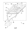
- FIG. 2 is a schematic of a battery operated system configured in accordance with an embodiment of the invention.
- battery packs As described above, a principal concern with battery packs is thermal management for purposes of providing reliable performance characteristics.
- thermal management of battery packs such as Li ion battery packs
- one traditional option for thermal control of battery packs has been to provide additional elements or components to externally heat and cool the battery pack.
- external cooling devices are generally inefficient, bulky, and contribute a significant amount of additional weight to the overall system.
- battery packs have been fabricated to include internal structures, such as cooling channels or passages, for cooling the cells directly.
- internal structures such as cooling channels or passages
- embodiments of the invention provide a new battery pack support configuration.
- a battery pack support can be configured to provide a location for mechanically supporting a battery pack in a device and provide efficient cooling and heating of the battery pack, while maintaining good isolation between fluids and the battery pack.
- a battery pack support can have a small profile and can be configured to contribute a minor amount of additional weight.
- FIGS. 1A-1F One exemplary configuration for a battery pack support in accordance with an embodiment of the invention is described below with respect to FIGS. 1A-1F .
- FIGS. 1A-1F show various views of an exemplary battery pack support 100 configured in accordance with an embodiment of the invention.
- the support 100 includes an upper plate 102 having a first major surface 102 a and a second major surface 102 b.
- the upper plate 102 serves at least two major functions.
- the upper plate 102 provides the structure for mechanically supporting a battery pack (not shown) in a battery-operated device (not shown).
- the support 100 can be attached or positioned in the battery operated device and a battery pack can be fastened to the first major surface 102 a .
- the upper plate 102 can include additional structures and features (not shown) for fastening a battery pack to the upper plate 102 .
- the upper plate 102 can include features for attaching the battery pack via one or more fastening devices, including, but not limited to, screws bolts, clamps, and straps, to name a few.
- the upper plate 102 can also include features on the first major surface 102 a that can be used to register or locate the battery modules. In such embodiments, such features can be machined, molded, attached or fastened onto this surface.
- the upper plate 102 In addition to supporting the battery pack, the upper plate 102 also serves as a cooling or heating element for the battery pack. Accordingly, in the various embodiments of the invention, the upper plate 102 can consist of a substantially rigid material with high thermal conductivity.
- the upper plate 102 can consist of a metal, including, but not limited to, corrosion resistant metals such as aluminum, copper, brass, or stainless steel. Other materials include thermally conductive plastics/polymers or composites.
- the various embodiments are not limited to any of the materials listed above, and any other substantially rigid material with high thermal conductivity can be used without limitation.
- the support 100 can also include at least one lower plate 104 positioned flush to second major surface 102 b of upper plate 102 .
- the lower plate 104 is used to define passages for directing a heating or cooling fluid through the support 100 .
- the term “fluid” refers to gases or liquids.
- the lower plate 104 is configured to include a set of connected protrusions 106 .
- the protrusions 106 in the lower plate 104 define at least a first manifold 106 a , a second manifold 106 b , and non-linear passages 106 c for providing a fluid connection between the manifolds 106 a and 106 b .
- non-linear passage refers to a passage including one or more curves, turns, or changes in direction.
- the non-linear passages are dimensioned and arranged to reduce or prevent boundary layer formation of fluid in the non-linear passages 106 c .
- the non-linear passages 106 c can also be configured to reduce or eliminate a pressure drop.
- the passages can have a semicircular cross-section profile and have direction changes that extend along a swept curve.
- the various embodiments are not limited to the specific configuration described herein.
- the first manifold 106 a , the second manifold 106 b , and the non-linear passages 106 c can be arranged such that the manifolds 106 a and 106 b are parallel to each other and the non-linear passages 106 c extend primarily in a second direction perpendicular to each of the manifolds 106 a and 106 b.
- the support 100 is illustrated as including multiple lower plates 104 , each having a single set of connected protrusions 106 .
- the invention is not limited in this regard.
- a single lower plate 104 can be provided with multiple sets of protrusions 106 .
- multiple lower plates 104 can be used, but one or more of the lower plates 104 can include two or more sets of protrusions 106 .
- a lower plate 104 with a set of protrusions 106 can be fabricated from any number of different materials.
- the selection of the material type and fabrication process can depend on cost restrictions, weight restrictions, and reliability requirements.
- a low-weight material that is resistant to corrosion can be used, such as some corrosion resistant metals or polymers.
- such materials can include aluminum, zinc, polyethylene, polyamide, polypropylene, or fiberglass.
- a thinner, higher weight can also be used.
- the lower plate 104 with the protrusions 106 can be fabricated in a variety of ways.
- the protrusions 106 can be embossed. That is, a substantially planar portion defining the lower plate 104 is formed first, and the protrusions 106 are then pressed or stamped into the lower plate 104 using a die or mold in combination with pressure, heat, or both.
- the lower plate 104 can be formed using a molding or extrusion process.
- the process to be used for forming the lower plate 104 can depend on (i) the type of material being used; (ii) the level of efficiency and productivity required; or (iii) both. For example, some types of materials can be more efficiently processed via embossing, such as metal sheets.
- each of the non-linear passages 106 c are shown as consisting of a plurality of semi-circular portions defining a serpentine passage between the manifolds 106 a and 106 b .
- a “serpentine passage” is a non-linear passage that extends along a path between the manifolds 106 a and 106 b having no portion traveling in a direction opposite to a linear path between a beginning and an end of the non-linear passage.
- the path can be symmetric with respect to this linear path. That is, turns or other changes in the non-linear passage can be distributed uniformly about the linear path.
- the non-linear path can be configured to follow a zigzag or sinusoidal pattern with respect to the linear path between a beginning and an end of the non-linear passage.
- a path is illustrated in FIG. 1D , in which each the non-linear passages 106 c extends along a linear path 106 d between the manifolds 106 a and 106 b and consists of a series of semicircular sections defining a zigzag or sinusoidal path with respect to the path 106 d .
- the various embodiments are not limited in this regard and any other types of serpentine passages can be used in the various embodiments without limitation.
- the serpentine passage can be asymmetric with respect to the linear path 106 d.
- the non-linear passages 106 c are shown as being configured to be nested or interlocking and being substantially identical.
- the terms “nested” or “interlocked” refer to configurations in which one non-linear passage fits into at least a portion of a space between another of the non-linear passages to provide a more compact arrangement of the non-linear passages.
- the various embodiments are not limited in this regard.
- at least one of the non-linear passages 106 c in the lower plate 104 can be different than the others.
- At least one of the non-linear passages 106 c in the lower plate 104 can be non-nested.
- the nested arrangement illustrated in FIG. 1D can provide a more compact arrangement of non-linear passages, allowing a larger number of non-linear passages in the lower plate 104 without the need to increase a size of the tower plate 104 .
- the height of the protrusions 106 can be selected so as to minimize the formation of a boundary layer when a fluid flows through the non-linear passages 106 c .
- the protrusions 106 can be configured to reduce pressure drops along the length of each of the passages based on the type of fluid to be used and a desired flow rate of the fluid. As a result, more effective heating or cooling of the upper plate 102 and the battery pack can be provided.
- the protrusions 106 associated with the non-linear passages 106 c can be molded or embossed using a curved shape to cause the non-linear passages 106 c to have a width (w) that is greater than about twice its height (h), as designated in FIG. 1E .
- the non-linear passages 106 c can define a portion of a circle (i.e., circular segment), an ellipse, or an oval.
- the width can be substantially larger than the height.
- the height cat be selected to be less than or equal to about 80% of the radius of the associated circle to provide a width that is at least about four times greater than the height (i.e., w>4 h).
- the dimensions and arrangement of the non-linear passages 106 c can be selected so as to limit the size for the support 100 .
- the height of the non-linear passages 106 c can be less than or equal to the thickness of the upper plate 102 .
- the dimensions of the upper plate 102 and the lower plate 104 can be selected to provide a small profile.
- the total thickness of the support 100 cat be at least 50 times less than a length of the upper plate 102 .
- the support 100 can further include a first conduit 108 and a second conduit 110 for circulating heating or cooling fluids in and out of the support 100 .
- the conduits 108 and 110 can be configured to include or mate with one or more components for coupling conduits to a source of heating or cooling fluids for the support 100 .
- such components can include adapters, connectors, tubing, and any other components for coupling the conduits 108 and 110 to a heating or cooling fluid source (not shown).
- the conduits 108 and 110 are also configured to be in fluid communication with the manifolds 106 a and 106 b , respectively.
- FIG. 2 is a schematic of a battery operated system 200 including a support 100 in accordance with an embodiment of the invention.
- a fluid source 202 is coupled to at least one of the conduits 108 and 110 .
- an inlet 204 and an outlet 206 are provided for coupling the fluid source 202 to the conduits 108 and 110 , respectively.
- a heating or cooling fluid is directed via the inlet 204 into the conduit 108 .
- the conduit 108 is in fluid communication with the manifold(s) 106 a .
- the fluid is directed by the first conduit 108 into the manifold(s) 106 a .
- the fluid in the manifold(s) 106 a is directed through the non-linear passages 106 c to the second manifold(s) 106 b , as shown in FIG. 2 .
- the non-linear passages 106 c permit the fluid to reach a significant portion of the lower plate 104 without the need to provide a large number of passages. Further, the flow of fluids with little or no boundary layer through the support 100 causes the upper plate 102 to be cooled or heated without formation of a significant gradient in temperature.
- the upper plate 102 provides substantially uniform cooling or heating of the battery 208 mounted thereon.
- the second conduit 110 is fluid communication with the manifold(s) 106 b .
- the fluid is directed into the second conduit 110 .
- the fluid travels out of the support 100 via the outlet 206 .
- a recirculation system can be provided. That is, the fluid is reused.
- the invention is not limited in this regard and the fluid in the outlet 206 can be discarded.
- a single inlet, outlet, and fluid source are illustrated in FIG. 2 , the invention is not limited in this regard. In the various embodiments, the number of each of these can vary. Additionally, separate inlets, outlets, and fluid sources can be provided for cooling versus heating.
- the fluid source 202 is shown as being outside of the battery operated system 200 , the invention is not limited in this regard. For example, in vehicular or mobile applications, the fluid source 202 can be located within a battery operated system.
- the conduits 108 and 110 can be coupled to the manifolds 106 a and 106 b in a variety of ways.
- the conduits 108 and 110 can be disposed on a first major surface 102 a of the upper plate 102 .
- the upper plate 102 can then be configured to include at least one first manifold opening 114 to provide access to the first manifold 106 a and at least one second manifold opening 118 to provide access to the second manifold 106 b .
- the first conduit 108 can include at least a first conduit opening 112 configured to mate with the first manifold opening 114 and the second conduit 110 can include at teas one second conduit opening 116 to mate with the second manifold opening 118 .
- the various embodiments are not limited to such a configuration.
- the conduits 108 and 110 can be disposed on the lower plate 104 or even along an edge of the plates 102 and 104 . Additional sections can then be provided to provide fluid communication between the conduits 108 and 110 and the manifolds 106 a and 106 b , respectively.
- the conduits 108 and 110 can be formed in a variety of shapes.
- the conduits 108 and 110 are each shown as having a rectangular outer shape and a circular inner shape to facilitate fluid flow and to secure of a battery pack in the space between the conduits 108 and 110 .
- the invention is not limited in this regard and any other inner or outer shapes can be used without limitation.
- the outer shape can be non-rectangular and the inner shape can be non-circular.
- FIGS. 1A-1F illustrate only two conduits 108 and 110 for supplying fluid flow for various manifolds, the invention is not limited in this regard.
- multiple conduits can be provided for directing fluids in or out of the support 100 .
- multiple conduits can be used to separate heating and cooling. That is, different sets of manifolds and non-linear passages can be used to provide cooling and heating. Accordingly, a first set of conduits can be associated with heating of the support 100 and a second set of conduits can be associated with cooling of the support 100 .
- the conduits can be formed from a variety of materials.
- the conduits 108 and 110 can be formed using materials with poor thermal conductivity to prevent a large thermal gradient from forming across the support 100 .
- thermally conductive materials can be used if the temperatures of the fluid entering the conduit 108 and leaving the second conduit 110 are not significantly different.
- such materials can include aluminum, zinc, polyethylene, polyamide, polypropylene, or fiberglass, to name a few.
- an insulation layer (not shown) can be provided for the conduits 108 and 110 .
- isolation can be provided between fluids in the conduits 108 and 110 or between the plates 102 and 104 and a battery pack mounted in or on the support 100 .
- a first mechanical seal 120 can be provided between the plates 102 and 104 to ensure that fluids are restricted to the manifolds 106 a and 106 b and the non-linear passages 106 c .
- mechanical seals 122 and 124 can also be provided to ensure that a battery pack disposed on the support 100 is not exposed to fluids traveling between the conduits 108 and 110 and the manifolds 106 a and 106 b .
- one or more of the mechanical seals 120 , 122 , 124 can also be used to provide mechanical fastening of the lower plate 104 , the first conduit 108 , or the second conduit 110 to the upper plate 102 of the support 100 .
- such mechanical seals can be provided in a variety of ways.
- the mechanical seals 120 , 122 , or 124 can be gaskets, o-rings, or any other type of mechanical seal device. These gaskets can be maintained in place using one or more adhesive materials or one or more fasteners (not shown).
- the mechanical seals 120 , 122 , or 124 can be provided using an adhesive sealant, such as an epoxy or other similar adhesive sealant.
- the various embodiments are not limited to the mechanical seals described above. Rather, the various components of the support 100 can be configured to include or support the use of any other type of mechanical seal.
- At least one additional sealing layer 126 can also be provided for the support 100 .
- the sealing layer 126 ea be a layer of material disposed over the first major surface 102 a of the upper plate 102 , including any of the conduits 108 and 110 disposed on the first major surface 102 a .
- the seating layer 126 can be configured to be substantially electrically insulating in order to provide additional electrical isolation between a battery pack and any fluids in the support 100 .
- the sealing layer 126 can be configured to provide a surface with a high coefficient of static friction to aid in securing of the battery pack to the support 100 .
- the sealing layer 126 can be configured to have a relatively high thermal conductivity to allow the upper plate 102 to provide sufficient heating or cooling of the battery pack.
- the sealing layer 126 can be configured to be of a sufficiently low thickness so as not to significantly hinder or retard the exchange of heat between the battery pack and the upper plate 102 .
- the sealing layer 126 can be a thin layer of an epoxy, rubber, or other similar material, such as a thermally conductive acrylic or silicon rubber.
- the support 100 can be configured to operate with a variety of cooling and heating fluids, including gases and liquids.
- Gases can include air, inert gases, and steam. However, any other gases can be used without limitation the various embodiments.
- gases can be provided to the support 100 via convective airflow or forced circulation, based on the particular cooling or heating requirements for the battery pack.
- Liquids can include liquids, such as water or glycol, molten solids, liquefied gases, and nanofluids (i.e., a liquid with suspended nanoparticles).
- Such gas or liquids can be supplied by a heater or chiller device (not shown) coupled to the conduits 108 and 110 .
- the type of fluid can depend on the various materials forming the support 100 . That is, the type of fluid can be selected such that is it relatively unreactive with the various components of the support 100 . Additionally, the fluid can include one or more anti-corrosive agents to prevent or limit the reactivity of the fluid with the various components of the support 100 . Alternatively, the various components of the support 100 can be configured to be relatively unreactive with the fluid. For example, the materials used to make the support 100 can be coated or treated in order to resist corrosion by the fluid. Alternatively, the interior of the conduits 108 and 110 , the manifolds 106 a and 106 b , and the non-linear passage 106 c can be coated with a corrosion inhibitor.
- FIGS. 1A-1F The system illustrated in FIGS. 1A-1F was fabricated with the following dimensions (in mm):
- This testing involved soaking the battery pack for 24 hours at an elevated ambient temperature (30° C. for 24 hours at roughly 80% SOC (State of Charge).
- the battery pack was then placed in a thermal chamber.
- a battery cycler was then used to simulate the vehicle load and to recharge the battery.
- the pack was then trickle charged to ⁇ 100% SOC.
- a discharge test was begun and the ambient temperature was raised to 40° C. Raising the ambient from 30° C. to 40° C. simulates the vehicle coming out of an overnight soak at 30° C. and being charged for a daytime 40° C. environment.
- the battery coolant (50/50 mix of ethylene glycol and water) was turned on for the pack. This was provided by an industrial chiller that controls flow rate (4 liters per minute) and 20° C. EGW inlet temperature to the battery pack. The pack was then configured to undergo a 1° C. discharge (70 amps) for roughly 1 hour until it was near 0% SOC. Thereafter, a c/2 charge started, which lasted about two hours. To protect the battery, the cycler was configured to trickle charge the battery for the last 10-20% of the charge cycle until ⁇ 100% SOC was reached. The coolant to the battery was never turned off during the test. This cycle of discharge and charge was repeated 5 times. This charge discharge cycle was selected to evaluate severe driving conditions and in a 40° C. climate.
- the battery support design disclosed herein can provide liquid cooling to the vehicle battery and allow it to perform in extreme warm weather climates without limiting current due to battery BMS thermistor temperatures forcing a current limiting condition.
- the battery BMS thermistor would begin to limit current at 45° C. and shuts down at 55° C.
Abstract
Description
Claims (21)
Priority Applications (2)
| Application Number | Priority Date | Filing Date | Title |
|---|---|---|---|
| US13/069,270 US8852780B2 (en) | 2011-03-22 | 2011-03-22 | Battery pack support with thermal control |
| PCT/US2012/029902 WO2012129274A2 (en) | 2011-03-22 | 2012-03-21 | Battery pack support with thermal control |
Applications Claiming Priority (1)
| Application Number | Priority Date | Filing Date | Title |
|---|---|---|---|
| US13/069,270 US8852780B2 (en) | 2011-03-22 | 2011-03-22 | Battery pack support with thermal control |
Publications (2)
| Publication Number | Publication Date |
|---|---|
| US20120244392A1 US20120244392A1 (en) | 2012-09-27 |
| US8852780B2 true US8852780B2 (en) | 2014-10-07 |
Family
ID=46877591
Family Applications (1)
| Application Number | Title | Priority Date | Filing Date |
|---|---|---|---|
| US13/069,270 Expired - Fee Related US8852780B2 (en) | 2011-03-22 | 2011-03-22 | Battery pack support with thermal control |
Country Status (2)
| Country | Link |
|---|---|
| US (1) | US8852780B2 (en) |
| WO (1) | WO2012129274A2 (en) |
Cited By (2)
| Publication number | Priority date | Publication date | Assignee | Title |
|---|---|---|---|---|
| US9761918B2 (en) | 2015-09-10 | 2017-09-12 | Ford Global Technologies, Llc | Vehicle traction battery assembly |
| US20200313260A1 (en) * | 2019-03-25 | 2020-10-01 | GM Global Technology Operations LLC | Cooling plate for a rechargeable energy storage system |
Families Citing this family (15)
| Publication number | Priority date | Publication date | Assignee | Title |
|---|---|---|---|---|
| US8448499B2 (en) | 2008-12-23 | 2013-05-28 | C A Casyso Ag | Cartridge device for a measuring system for measuring viscoelastic characteristics of a sample liquid, a corresponding measuring system, and a corresponding method |
| DK2555704T3 (en) | 2010-04-08 | 2019-08-05 | Hemosonics Llc | VIEW OF HEMOSTATIC PARAMETERS |
| EP2676143B1 (en) | 2011-02-15 | 2023-11-01 | Hemosonics, Llc | Characterization of blood hemostasis and oxygen transport parameters |
| PT2676136T (en) | 2011-02-15 | 2021-03-25 | Hemosonics Llc | Devices, systems and methods for evaluation of hemostasis |
| US20120294767A1 (en) | 2011-05-19 | 2012-11-22 | Hemosonics Llc | Portable hemostasis analyzer |
| US8999547B2 (en) * | 2011-12-22 | 2015-04-07 | Samsung Sdi Co., Ltd. | Battery module |
| US20130260195A1 (en) * | 2012-04-02 | 2013-10-03 | Shijin Long | Oil-cooled lithium battery module |
| US9806381B2 (en) * | 2014-01-16 | 2017-10-31 | Ford Global Technologies, Llc | Serpentine cooling element for battery assembly |
| US10175225B2 (en) | 2014-09-29 | 2019-01-08 | C A Casyso Ag | Blood testing system and method |
| KR101947887B1 (en) * | 2017-01-03 | 2019-02-13 | 삼성에스디아이 주식회사 | Battery pack housing |
| KR20180083140A (en) * | 2017-01-12 | 2018-07-20 | 삼성에스디아이 주식회사 | Battery pack housing and battery pack including the same |
| KR101916429B1 (en) * | 2017-03-30 | 2018-11-07 | 엘지전자 주식회사 | Battery pack for vehicle and vehicle |
| CN110691972B (en) | 2017-04-20 | 2022-11-04 | 海默索尼克斯有限公司 | Disposable system for hemostatic function analysis |
| KR20200074320A (en) * | 2018-12-14 | 2020-06-25 | 현대자동차주식회사 | Battery pack |
| WO2022217264A1 (en) * | 2021-04-09 | 2022-10-13 | Polestar Automotive Usa Inc. | Electric vehicle battery cooling through extrusions |
Citations (11)
| Publication number | Priority date | Publication date | Assignee | Title |
|---|---|---|---|---|
| US5756227A (en) | 1994-11-18 | 1998-05-26 | Honda Giken Kogyo Kabushiki Kaisha | Battery assembly with temperature control mechanism |
| US20010031392A1 (en) | 2000-04-12 | 2001-10-18 | Matsushita Electric Industrial Co., Ltd And Toyota Jidosha Kabushiki Kaisha | Mount frame for battery modules and method for mounting battery modules using the same |
| US20030232239A1 (en) | 1998-08-23 | 2003-12-18 | Philippe Gow | Monoblock battery assembly with cross-flow cooling |
| US20050170240A1 (en) | 2004-02-04 | 2005-08-04 | Daimlerchrysler Ag | Electrochemical energy store |
| US20060068267A1 (en) | 2004-09-24 | 2006-03-30 | Hydrogenics Corporation | Modification of membrane electrode assembly |
| US20080193830A1 (en) | 2006-10-13 | 2008-08-14 | Enerdel, Inc. | Battery assembly with temperature control device |
| US20090214941A1 (en) | 2006-10-13 | 2009-08-27 | Derrick Scott Buck | Battery assembly |
| US20090258289A1 (en) | 2008-04-09 | 2009-10-15 | Gm Global Technology Operations, Inc. | Battery cooling plate design with discrete channels |
| US20100261046A1 (en) | 2007-09-11 | 2010-10-14 | Daimler Ag | Heat Exchanger Unit and Electrochemical Energy Accumulator with a Heat Exchanger Unit |
| US7858220B2 (en) * | 2005-08-31 | 2010-12-28 | Sanyo Electric Co., Ltd. | Battery array for cooling battery modules with cooling air |
| US20120231319A1 (en) | 2009-11-09 | 2012-09-13 | Enerdel, Inc. | Structural and thermal management component |
-
2011
- 2011-03-22 US US13/069,270 patent/US8852780B2/en not_active Expired - Fee Related
-
2012
- 2012-03-21 WO PCT/US2012/029902 patent/WO2012129274A2/en active Application Filing
Patent Citations (12)
| Publication number | Priority date | Publication date | Assignee | Title |
|---|---|---|---|---|
| US5756227A (en) | 1994-11-18 | 1998-05-26 | Honda Giken Kogyo Kabushiki Kaisha | Battery assembly with temperature control mechanism |
| US20030232239A1 (en) | 1998-08-23 | 2003-12-18 | Philippe Gow | Monoblock battery assembly with cross-flow cooling |
| US6864013B2 (en) * | 1998-08-23 | 2005-03-08 | Chevron Texaco Technology Ventures, Llc | Monoblock battery assembly with cross-flow cooling |
| US20010031392A1 (en) | 2000-04-12 | 2001-10-18 | Matsushita Electric Industrial Co., Ltd And Toyota Jidosha Kabushiki Kaisha | Mount frame for battery modules and method for mounting battery modules using the same |
| US20050170240A1 (en) | 2004-02-04 | 2005-08-04 | Daimlerchrysler Ag | Electrochemical energy store |
| US20060068267A1 (en) | 2004-09-24 | 2006-03-30 | Hydrogenics Corporation | Modification of membrane electrode assembly |
| US7858220B2 (en) * | 2005-08-31 | 2010-12-28 | Sanyo Electric Co., Ltd. | Battery array for cooling battery modules with cooling air |
| US20080193830A1 (en) | 2006-10-13 | 2008-08-14 | Enerdel, Inc. | Battery assembly with temperature control device |
| US20090214941A1 (en) | 2006-10-13 | 2009-08-27 | Derrick Scott Buck | Battery assembly |
| US20100261046A1 (en) | 2007-09-11 | 2010-10-14 | Daimler Ag | Heat Exchanger Unit and Electrochemical Energy Accumulator with a Heat Exchanger Unit |
| US20090258289A1 (en) | 2008-04-09 | 2009-10-15 | Gm Global Technology Operations, Inc. | Battery cooling plate design with discrete channels |
| US20120231319A1 (en) | 2009-11-09 | 2012-09-13 | Enerdel, Inc. | Structural and thermal management component |
Non-Patent Citations (1)
| Title |
|---|
| International Search Report and Written Opinion in PCT/US2012/029902, Sep. 2012, 8 pgs. |
Cited By (4)
| Publication number | Priority date | Publication date | Assignee | Title |
|---|---|---|---|---|
| US9761918B2 (en) | 2015-09-10 | 2017-09-12 | Ford Global Technologies, Llc | Vehicle traction battery assembly |
| US20200313260A1 (en) * | 2019-03-25 | 2020-10-01 | GM Global Technology Operations LLC | Cooling plate for a rechargeable energy storage system |
| CN111740047A (en) * | 2019-03-25 | 2020-10-02 | 通用汽车环球科技运作有限责任公司 | Cooling plate for rechargeable energy storage system |
| US10978755B2 (en) * | 2019-03-25 | 2021-04-13 | GM Global Technology Operations LLC | Cooling plate for a rechargeable energy storage system |
Also Published As
| Publication number | Publication date |
|---|---|
| WO2012129274A2 (en) | 2012-09-27 |
| US20120244392A1 (en) | 2012-09-27 |
| WO2012129274A3 (en) | 2013-01-31 |
Similar Documents
| Publication | Publication Date | Title |
|---|---|---|
| US8852780B2 (en) | Battery pack support with thermal control | |
| Jilte et al. | Thermal performance of a novel confined flow Li-ion battery module | |
| KR102519046B1 (en) | apparatus for controlling temperature of coolant of battery system cooled by water and method thereof | |
| CN103579713B (en) | With the battery of solid-state cooling | |
| CN103797610B (en) | There is the battery pack of novel cooling structure | |
| CN202651315U (en) | Cooling/heating device of battery cells | |
| US8861202B2 (en) | Integrated thermal and structural management solution for Rechargeable Energy Storage System assembly | |
| US20160190663A1 (en) | Busbars with integrated cooling system for vehicle battery assemblies | |
| US20160211558A1 (en) | Battery thermal management systems, apparatuses, and methods | |
| KR101563405B1 (en) | Apparatus for contacting heat exchanger elements with battery modules of motor vehicle | |
| US8940425B2 (en) | Plastic liquid heat exchanger for battery cooling system | |
| US9907216B2 (en) | Apparatus with direct cooling pathway for cooling both sides of power semiconductor | |
| US20140023906A1 (en) | Power supply apparatus and vehicle having the same | |
| US10297882B2 (en) | Battery system with a temperature-control element containing a temperature-control channel and a bypass and motor vehicle containing the battery system | |
| CN107453007A (en) | On-vehicle battery heat management device | |
| US20160079639A1 (en) | Cooling fin for a battery cell | |
| EP3293794B1 (en) | Methods and systems for busbar cooling | |
| US20180337433A1 (en) | Dual-sided propulsion battery coolant system | |
| CN207459030U (en) | Battery component and vehicle | |
| WO2013105756A1 (en) | Secondary battery module and secondary battery pack | |
| US9410746B2 (en) | Temperature-regulating element | |
| US20140090811A1 (en) | Heat exchanger | |
| CN115917837A (en) | Battery module and battery pack including the same | |
| KR20190107400A (en) | Battery Pack of Energy Storage System | |
| CN112352343B (en) | Modular assembly for circulation of heat transfer fluid in a motor vehicle battery |
Legal Events
| Date | Code | Title | Description |
|---|---|---|---|
| AS | Assignment |
Owner name: ENERDEL, INC., INDIANA Free format text: ASSIGNMENT OF ASSIGNORS INTEREST;ASSIGNORS:KLEIMAN, RICHARD;ALFORD, STEVE;GARNER, DAVID;AND OTHERS;SIGNING DATES FROM 20110112 TO 20110312;REEL/FRAME:025999/0912 |
|
| AS | Assignment |
Owner name: BZINFIN S.A., SWITZERLAND Free format text: SECURITY AGREEMENT;ASSIGNORS:ENERDEL, INC.;ENERFUEL, INC.;ENER1, INC.;AND OTHERS;REEL/FRAME:027370/0979 Effective date: 20111116 |
|
| AS | Assignment |
Owner name: ENER1, INC., INDIANA Free format text: TERMINATION AND RELEASE OF SECURITY INTEREST IN PATENTS;ASSIGNOR:BZINFIN, S.A.;REEL/FRAME:027982/0854 Effective date: 20120330 Owner name: ENERDEL, INC., ILLINOIS Free format text: TERMINATION AND RELEASE OF SECURITY INTEREST IN PATENTS;ASSIGNOR:BZINFIN, S.A.;REEL/FRAME:027982/0854 Effective date: 20120330 Owner name: ENERFUEL, INC., FLORIDA Free format text: TERMINATION AND RELEASE OF SECURITY INTEREST IN PATENTS;ASSIGNOR:BZINFIN, S.A.;REEL/FRAME:027982/0854 Effective date: 20120330 Owner name: NANO ENER, INC., FLORIDA Free format text: TERMINATION AND RELEASE OF SECURITY INTEREST IN PATENTS;ASSIGNOR:BZINFIN, S.A.;REEL/FRAME:027982/0854 Effective date: 20120330 |
|
| AS | Assignment |
Owner name: WILMINGTON TRUST, NATIONAL ASSOCIATION, MINNESOTA Free format text: PATENT SECURITY AGREEMENT;ASSIGNORS:ENER1, INC.;ENERDEL, INC.;ENERFUEL, INC.;AND OTHERS;REEL/FRAME:027999/0516 Effective date: 20120330 |
|
| FEPP | Fee payment procedure |
Free format text: MAINTENANCE FEE REMINDER MAILED (ORIGINAL EVENT CODE: REM.) |
|
| LAPS | Lapse for failure to pay maintenance fees |
Free format text: PATENT EXPIRED FOR FAILURE TO PAY MAINTENANCE FEES (ORIGINAL EVENT CODE: EXP.); ENTITY STATUS OF PATENT OWNER: SMALL ENTITY |
|
| STCH | Information on status: patent discontinuation |
Free format text: PATENT EXPIRED DUE TO NONPAYMENT OF MAINTENANCE FEES UNDER 37 CFR 1.362 |
|
| FP | Expired due to failure to pay maintenance fee |
Effective date: 20181007 |