US8852776B2 - Battery connection for a power tool - Google Patents
Battery connection for a power tool Download PDFInfo
- Publication number
- US8852776B2 US8852776B2 US12/369,077 US36907709A US8852776B2 US 8852776 B2 US8852776 B2 US 8852776B2 US 36907709 A US36907709 A US 36907709A US 8852776 B2 US8852776 B2 US 8852776B2
- Authority
- US
- United States
- Prior art keywords
- axis
- power tool
- battery
- tool
- battery pack
- Prior art date
- Legal status (The legal status is an assumption and is not a legal conclusion. Google has not performed a legal analysis and makes no representation as to the accuracy of the status listed.)
- Active, expires
Links
Images


Classifications
-
- H01M2/1066—
-
- H—ELECTRICITY
- H01—ELECTRIC ELEMENTS
- H01M—PROCESSES OR MEANS, e.g. BATTERIES, FOR THE DIRECT CONVERSION OF CHEMICAL ENERGY INTO ELECTRICAL ENERGY
- H01M50/00—Constructional details or processes of manufacture of the non-active parts of electrochemical cells other than fuel cells, e.g. hybrid cells
- H01M50/20—Mountings; Secondary casings or frames; Racks, modules or packs; Suspension devices; Shock absorbers; Transport or carrying devices; Holders
- H01M50/247—Mountings; Secondary casings or frames; Racks, modules or packs; Suspension devices; Shock absorbers; Transport or carrying devices; Holders specially adapted for portable devices, e.g. mobile phones, computers, hand tools or pacemakers
-
- H—ELECTRICITY
- H01—ELECTRIC ELEMENTS
- H01M—PROCESSES OR MEANS, e.g. BATTERIES, FOR THE DIRECT CONVERSION OF CHEMICAL ENERGY INTO ELECTRICAL ENERGY
- H01M50/00—Constructional details or processes of manufacture of the non-active parts of electrochemical cells other than fuel cells, e.g. hybrid cells
- H01M50/20—Mountings; Secondary casings or frames; Racks, modules or packs; Suspension devices; Shock absorbers; Transport or carrying devices; Holders
- H01M50/202—Casings or frames around the primary casing of a single cell or a single battery
-
- H—ELECTRICITY
- H01—ELECTRIC ELEMENTS
- H01M—PROCESSES OR MEANS, e.g. BATTERIES, FOR THE DIRECT CONVERSION OF CHEMICAL ENERGY INTO ELECTRICAL ENERGY
- H01M50/00—Constructional details or processes of manufacture of the non-active parts of electrochemical cells other than fuel cells, e.g. hybrid cells
- H01M50/20—Mountings; Secondary casings or frames; Racks, modules or packs; Suspension devices; Shock absorbers; Transport or carrying devices; Holders
- H01M50/244—Secondary casings; Racks; Suspension devices; Carrying devices; Holders characterised by their mounting method
-
- Y—GENERAL TAGGING OF NEW TECHNOLOGICAL DEVELOPMENTS; GENERAL TAGGING OF CROSS-SECTIONAL TECHNOLOGIES SPANNING OVER SEVERAL SECTIONS OF THE IPC; TECHNICAL SUBJECTS COVERED BY FORMER USPC CROSS-REFERENCE ART COLLECTIONS [XRACs] AND DIGESTS
- Y02—TECHNOLOGIES OR APPLICATIONS FOR MITIGATION OR ADAPTATION AGAINST CLIMATE CHANGE
- Y02E—REDUCTION OF GREENHOUSE GAS [GHG] EMISSIONS, RELATED TO ENERGY GENERATION, TRANSMISSION OR DISTRIBUTION
- Y02E60/00—Enabling technologies; Technologies with a potential or indirect contribution to GHG emissions mitigation
- Y02E60/10—Energy storage using batteries
-
- Y02E60/12—
Definitions
- the present invention relates to power tools and battery packs, and, more particularly, to a power tool having an angled battery connection port for a battery pack.
- the battery connection port of a battery-operated power tool may be located on the power tool in a variety of positions.
- the battery connection port for a battery-operated power tool is often in a location that can create cumbersome operation for a user.
- the location of the battery pack may make it inconvenient for a user to both use the power tool and simultaneously assess the state of charge of the battery pack.
- the user may find that the battery pack location creates an obstacle to proper handling of the power tool.
- the invention provides a power tool.
- the power tool includes a housing configured to house a motor.
- the housing defines a body axis and has a hand grip for a user, wherein the hand grip is positioned between a first end and a second end of the housing.
- the power tool further includes a tool element positioned at the first end of the housing and a battery connection port adapted to receive a battery pack.
- the battery connection port defines a removal axis for the battery pack and includes a first portion located at one end of the removal axis and a second portion located at an other end of the removal axis opposite the first portion. The second portion is positioned closer to the tool end than the first portion.
- the invention provides a battery-operated power tool.
- the battery-operated power tool includes a housing assembly configured to house a motor.
- the housing assembly defines a body axis and has a hand grip for a user, wherein the hand grip is positioned between a first end and a second end of the housing.
- the battery-operated power tool further includes a tool element positioned at the first end of the housing and a connection port adapted to receive a battery pack having a fuel gauge.
- the connection port includes an interface surface having a first portion and a second portion. The second portion is positioned closer to the first end than the first portion, and the first portion is positioned at an angle of less than ninety degrees measured from the body axis.
- the invention provides a battery-operated power tool.
- the battery-operated power tool includes a housing configured to house a motor.
- the housing defines a body axis and has a hand grip for a user.
- the hand grip is positioned between a first end and a second end of the housing.
- the battery-operated power tool further includes a side handle extending from the housing, a tool element positioned at the first end of the housing, and a connection port adapted to receive a battery pack.
- the connection port includes an interface surface having a first portion and a second portion. The second portion is positioned closer to the tool end than the first portion.
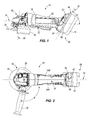
- FIG. 1 is a side view of a power tool and battery pack according to one embodiment of the present invention.
- FIG. 2 is a top view of the power tool and battery pack shown in FIG. 1 .
- FIG. 3 is an exploded view of a portion of the housing assembly of the power tool of FIG. 1 .
- FIG. 4 is a view of the connecting configuration of the power tool of FIG. 1 .
- FIG. 5 is a front perspective view of one type of battery pack for use with the power tool.
- FIG. 6 is a rear perspective view of the battery pack of FIG. 3 .
- FIGS. 1-2 illustrate a power tool 10 including a battery pack 14 .
- the power tool 10 is shown as a grinder. In other embodiments, the power tool may be another hand-held power tool, such as, for example, a reciprocating saw, a router, a drill, a screwdriver, a sander, a circular saw, a band saw, or other handheld power tool.
- the power tool 10 includes a housing assembly 18 , an actuator 22 , a hand grip 26 , a side handle 30 , a tool element or grinding blade 34 , a guard 38 , a fuel gauge 42 , and a connection port 46 adapted to receive the battery pack 14 .
- the housing assembly 18 includes the main handle portion or hand grip 26 and the actuator 22 .
- the actuator 22 is formed on a lower surface of the housing assembly 18 and extends outwardly from the housing assembly 18 for engagement by a user's finger or thumb.
- the actuator 22 is shown as a two-position lever; however, in other embodiments, the actuator may be a button, trigger, or other mechanism capable of actuation by a user. In other embodiments, the actuator has other orientations and locations.
- the housing assembly 18 houses a drive mechanism, a motor, and a spindle. Together, the drive mechanism, the motor, and the spindle are operable to rotate the grinding blade 34 generally about a tool axis 50 for working on a workpiece. In other embodiments, the drive mechanism, the motor, and the spindle can also or alternatively reciprocate the tool element along the tool axis 50 for working on a workpiece.
- a guard 38 at least partially surrounds the grinding blade 34 to provide a guard or shield around the grinding blade 34 .
- the guard 38 may be manufactured from plastic, metal, or other type of material capable of providing the guard function.
- the guard 38 is coupled to the drive mechanism.
- the side handle 30 extends from the power tool at an angle ⁇ with respect to a body axis 74 .
- the side handle 30 is configured to provide an additional hand grip for the user.
- the housing assembly 18 defines the body axis 74 , which as shown, is substantially perpendicular with respect to the tool axis 50 .
- the body axis 74 extends along the longitudinal length of the power tool.
- the angle ⁇ is greater than ninety degrees but less than 180 degrees. In other embodiments, the angle ⁇ may be less than ninety degrees or greater than ninety degrees.
- the housing assembly 18 is formed from two halves 54 A, 54 B.
- the housing assembly 18 has a rear end 58 and a tool end 62 .
- the housing is formed as a single integral member, or alternatively, is formed from three or more interconnected members.
- the connecting port 46 includes a receiving portion having grooves 66 and projections 70 .
- the grooves 66 and projections 70 are operable to engage a complementary connecting port 82 of the battery pack 14 ( FIGS. 5 and 6 ).
- the connecting port of the power tool also includes a terminal assembly positioned between forward ends of the grooves and projections and electrically connected to an electrical circuit, which extends through the power tool and is electrically connected to the motor.
- the terminal assembly or a portion of the terminal assembly can be positioned in the projections.
- the connecting port 46 of the power tool 10 includes an interface surface 68 having an upper portion 63 and a lower portion 64 .
- the interface surface 68 is sloped such that the lower portion 64 is positioned closer to the tool end 62 than the upper portion 63 .
- the interface surface 68 is sloped with respect to the body axis 74 to define a removal axis 78 .
- the removal axis 78 is inclined such that the upper portion 63 is positioned at an acute angle a measured from the body axis 74 .
- angle a is approximately twenty-five (25) degrees.
- the removal axis may be inclined at an angle a that is greater than twenty-five degrees from the body axis but less than ninety degrees. In still other embodiments, the removal axis may be sloped at an angle a that is less than twenty-five degrees from the body axis. An angled removal axis provides a more streamlined tool configuration such that the battery pack does not interfere with the user during operation of the power tool.
- the connecting port 82 of the battery pack 14 includes outwardly extending guide rails 86 extending horizontally along an upper surface of the battery pack and protrusions 90 formed along and extending outwardly along exterior sides of the guide rails 86 .
- the guide rails 86 and the protrusions 90 are operable to inter-engage with the grooves 66 and projections 70 on the connecting port 46 of the housing assembly 18 to removably support the battery pack 14 on the power tool 10 .
- the guide rails and the protrusions have other relative positions and orientations within the connecting port of the battery pack.
- the connecting port may also include a terminal assembly, which is electrically connected to the terminal assembly of the power tool to supply electrical power to the electrical circuit of the power tool.
- the terminal assembly is positioned on an upper surface of the battery pack between forward ends of the guide rails.
- the terminal assembly or a portion of the terminal assembly is supported in the guide rails of the battery pack.
- at least a portion of the terminal assembly of the power tool is supported in the projections of the power tool for engagement with the terminal assembly or the portion of the terminal assembly supported in the battery pack.
- a fuel gauge 42 provides a visual indication of the state of the charge of the battery pack 14 .
- a microprocessor (not shown) enables the function of the fuel gauge 42 .
- the fuel gauge 42 includes a push button 94 configured to be depressible by the user to activate the visual indication and a plurality of indicators 98 .
- the indicators 98 are illustrated as a series of square-shaped lights that are alternately lit to indicate certain battery characteristics, such as, but not limited to, battery charge remaining or battery charge used. However, in other embodiments, the indicators can be any shape or configuration that will indicate a certain battery characteristic to the user.
- the microprocessor enables the fuel gauge 42 whether or not the push button 94 is depressed during time periods when the battery pack 14 is active (e.g., during charging and/or discharging).
- the fuel gauge 42 is operational during charging.
- the microprocessor automatically enables the fuel gauge 42 to display the current state of charge of the battery pack 14 continuously or periodically (e.g., after certain predetermined time intervals or during periods of low current draw/supply), in response to certain battery characteristics (e.g., when the current state of charge reaches certain defined thresholds, such as, every 5% increase in state of charge), or in response to certain stages, modes, or changes in the charge cycle.
- the microprocessor enables the fuel gauge 42 in response to the depression of the push button 94 when the battery pack 14 is active.
- the fuel gauge 42 is enabled via a touch pad, a switch, or the like.
- the battery pack 14 includes another push button or switch (not shown) for enabling and disabling an automatic displaying mode.
- a user selects whether to have the circuit operate in an automatic displaying mode or operate in a manual displaying mode.
- the automatic displaying mode includes the fuel gauge 42 displaying the current state of charge of the battery pack 14 without user activation.
- the fuel gauge 42 displays the current state of charge of the battery pack 14 periodically (e.g., after certain predetermined time intervals), in response to certain battery characteristics (e.g., when the current state of charge reaches certain defined thresholds, such as, every 5% increase or decrease in state of charge), or the like.
- the manual displaying mode includes the fuel gauge 42 displaying the current state of charge in response to user activation, such as, for example, the depression of the push button 94 .
- the push button 94 is disabled when the circuit is operating in the automatic displaying mode. In other constructions, the push button 94 still enables the fuel gauge 42 even when the circuit is operating in the automatic displaying mode.
- the automatic displaying mode is enabled and disabled via the push button 94 , a control signal from an electrical device, such as, for example, a power tool 10 or battery charger, or the like.
- the battery pack 14 is aligned with the power tool 10 along the removal axis 78 such that the guide rails 86 and the protrusions 90 of the battery pack 14 are aligned with the projections 70 and grooves 66 of the power tool 10 .
- the battery pack 14 is then moved rearwardly along the removal axis 78 to interconnect the guide rails 86 and the protrusions 90 of the battery pack 14 and the projections 70 and grooves 66 of the power tool 10 .
- the terminal assembly of the power tool is electrically connected to the terminal assembly of the battery pack.
- the user grips the housing assembly 18 with one hand and the battery pack 14 with the second hand. The user can then slide the battery pack 14 along the guide rails 86 and away from the power tool 10 .
- the angled connecting port 46 increases visibility of the fuel gauge 42 to the user.
- a non-angled connection port i.e., when the battery pack is horizontal or perpendicular with respect to the body axis
- the fuel gauge on the battery pack is difficult for the user to view without manipulation of the power tool.
- an angled connection port 46 allows the user to operate and view the fuel gauge 42 without having to otherwise manipulate the power tool 10 in order to view the fuel gauge 42 .
Abstract
Description
Claims (22)
Priority Applications (1)
| Application Number | Priority Date | Filing Date | Title |
|---|---|---|---|
| US12/369,077 US8852776B2 (en) | 2008-02-11 | 2009-02-11 | Battery connection for a power tool |
Applications Claiming Priority (2)
| Application Number | Priority Date | Filing Date | Title |
|---|---|---|---|
| US2773408P | 2008-02-11 | 2008-02-11 | |
| US12/369,077 US8852776B2 (en) | 2008-02-11 | 2009-02-11 | Battery connection for a power tool |
Publications (2)
| Publication Number | Publication Date |
|---|---|
| US20090202894A1 US20090202894A1 (en) | 2009-08-13 |
| US8852776B2 true US8852776B2 (en) | 2014-10-07 |
Family
ID=40527165
Family Applications (1)
| Application Number | Title | Priority Date | Filing Date |
|---|---|---|---|
| US12/369,077 Active 2031-12-12 US8852776B2 (en) | 2008-02-11 | 2009-02-11 | Battery connection for a power tool |
Country Status (3)
| Country | Link |
|---|---|
| US (1) | US8852776B2 (en) |
| DE (1) | DE102009008544A1 (en) |
| GB (1) | GB2457173A (en) |
Cited By (3)
| Publication number | Priority date | Publication date | Assignee | Title |
|---|---|---|---|---|
| US20160199962A1 (en) * | 2013-09-03 | 2016-07-14 | Robert Bosch Gmbh | Grinding Machine Housing Device |
| US20180290322A1 (en) * | 2017-04-10 | 2018-10-11 | Nanjing Chervon Industry Co., Ltd. | Hand-held cutting tool |
| US11440176B2 (en) | 2017-01-24 | 2022-09-13 | Techtronic Cordless Gp | Battery terminal holder for electric tools |
Families Citing this family (12)
| Publication number | Priority date | Publication date | Assignee | Title |
|---|---|---|---|---|
| DE102010039152A1 (en) * | 2010-08-10 | 2012-02-16 | Robert Bosch Gmbh | Device for surface treatment, in particular grinding device, polishing device od. Like. |
| US9630310B2 (en) | 2013-02-01 | 2017-04-25 | Makita Corporation | Electric tool |
| JP6059032B2 (en) | 2013-02-01 | 2017-01-11 | 株式会社マキタ | Electric tool |
| JP6043195B2 (en) | 2013-02-01 | 2016-12-14 | 株式会社マキタ | Electric tool |
| CN106553159B (en) * | 2015-09-28 | 2020-11-17 | 苏州宝时得电动工具有限公司 | Electric tool |
| AU2017375491B2 (en) | 2016-12-16 | 2021-06-10 | Milwaukee Electric Tool Corporation | Battery pack interface |
| TWM565411U (en) | 2016-12-16 | 2018-08-11 | 美商米沃奇電子工具公司 | Battery pack switch |
| CN212485397U (en) | 2017-03-24 | 2021-02-05 | 米沃奇电动工具公司 | Battery pack and electrical assembly |
| TWM578899U (en) | 2017-06-30 | 2019-06-01 | 美商米沃奇電子工具公司 | Electrical combination, power tool system, electric motor assembly, electric motor, battery pack and motor assembly |
| USD887980S1 (en) * | 2018-02-16 | 2020-06-23 | Milwaukee Electric Tool Corporation | Interface portion of a battery pack |
| US20220021062A1 (en) | 2020-07-15 | 2022-01-20 | Emerson Electric Co. | Battery packs for battery-powered appliances and connection system for same |
| DE102021203108A1 (en) | 2021-03-29 | 2022-09-29 | Robert Bosch Gesellschaft mit beschränkter Haftung | battery pack |
Citations (36)
| Publication number | Priority date | Publication date | Assignee | Title |
|---|---|---|---|---|
| US3999110A (en) | 1975-02-06 | 1976-12-21 | The Black And Decker Manufacturing Company | Battery pack and latch |
| US4597227A (en) * | 1984-02-18 | 1986-07-01 | C. & E. Fein Gmbh & Co. | Device for attaching a tool |
| US4625462A (en) | 1984-08-29 | 1986-12-02 | Makita Electric Works, Ltd. | Cordless electric finishing sander |
| USD295824S (en) * | 1984-11-22 | 1988-05-24 | Ryobi Ltd. | Portable electric grinder |
| USD347153S (en) | 1992-11-17 | 1994-05-24 | Makita Corporation | Portable electric grinder |
| USD351772S (en) | 1993-11-01 | 1994-10-25 | Black & Decker Inc. | Angle grinder |
| US6057608A (en) | 1998-08-13 | 2000-05-02 | Black & Decker Inc. | Cordless power tool system |
| JP2001143678A (en) | 1999-11-15 | 2001-05-25 | Makita Corp | Battery pack and power tool |
| US6304058B2 (en) | 1998-08-13 | 2001-10-16 | Black & Decker Inc. | Cordless power tool system |
| US6329788B1 (en) | 1998-08-13 | 2001-12-11 | Black & Decker Inc. | Cordless power tool system |
| JP2001351592A (en) | 2000-06-06 | 2001-12-21 | Makita Corp | Rechargeable power tool |
| JP2002260619A (en) | 2001-03-01 | 2002-09-13 | Hitachi Koki Co Ltd | Battery-pack mounting device of battery tool |
| US6562509B1 (en) | 1999-06-16 | 2003-05-13 | Snap-On Technologies, Inc. | Multi-use lead-acid power pack for use with a cordless power hand tool and other loads |
| US6568089B1 (en) | 1999-06-04 | 2003-05-27 | Porter-Cable/Delta | Reciprocating saw having compact configuration and independent stability |
| US20030102844A1 (en) | 2001-11-24 | 2003-06-05 | Rudolph Bailey | Automatic selfcharging power tools |
| US20040088817A1 (en) | 2002-11-12 | 2004-05-13 | Cochran John R. | AC/DC hand portable wet/dry vacuum having improved portability and convenience |
| US20050073282A1 (en) | 2003-10-03 | 2005-04-07 | Carrier David A. | Methods of discharge control for a battery pack of a cordless power tool system, a cordless power tool system and battery pack adapted to provide over-discharge protection and discharge control |
| US20050077878A1 (en) | 2003-10-14 | 2005-04-14 | Dave Carrier | Protection methods, protection circuits and protective devices for secondary batteries, a power tool, charger and battery pack adapted to provide protection against fault conditions in the battery pack |
| US6913087B1 (en) | 2004-01-30 | 2005-07-05 | Black & Decker Inc. | System and method for communicating over power terminals in DC tools |
| US6921285B2 (en) * | 2002-03-22 | 2005-07-26 | Robert Bosch Gmbh | Battery pack system for hand power tools |
| US6935438B2 (en) * | 2000-08-16 | 2005-08-30 | Robert Bosch Gmbh | Battery operated electrical tool |
| US6983809B2 (en) | 2000-05-11 | 2006-01-10 | Robert Bosch Gmbh | Machine tool, especially a hand machine tool |
| US20060071643A1 (en) | 2004-10-04 | 2006-04-06 | Carrier David A | Method and device for monitoring battery cells of a battery pack and method and arrangement for balancing battery cell voltages during charge |
| WO2006052825A2 (en) * | 2004-11-04 | 2006-05-18 | Milwaukee Electric Tool Corporation | Power tools, battery chargers and batteries |
| US7063171B2 (en) | 2001-01-31 | 2006-06-20 | Katsuyuki Totsu | Motor-driven rotary tool with internal heating temperature detecting function |
| US20060151189A1 (en) | 2005-01-10 | 2006-07-13 | Shuming Wu | Power tool with battery power supply |
| USD525847S1 (en) | 2005-03-31 | 2006-08-01 | Campbell Hauseld/Scott Fetzer Company | Portion of an electric drill |
| USD527966S1 (en) | 2006-01-17 | 2006-09-12 | Makita Corporation | Portable electric grinder |
| US20060220605A1 (en) | 2005-04-04 | 2006-10-05 | Kazuhiko Funabashi | Cordless power tool with overcurrent protection circuit |
| US20060220612A1 (en) | 2005-03-31 | 2006-10-05 | Feldmann William M | Modular panel for a power tool |
| US7248019B2 (en) | 2002-12-04 | 2007-07-24 | Max Co., Ltd. | Cordless power tool |
| US20070193761A1 (en) | 2005-11-04 | 2007-08-23 | Brotto Daniele C | Cordless power tool system with improved power output |
| US20070240892A1 (en) | 2005-11-04 | 2007-10-18 | Black & Decker Inc. | Cordless outdoor power tool system |
| US7291062B2 (en) | 2004-09-29 | 2007-11-06 | Robert Bosch Gmbh | Manual power grinder, in particular a battery-powered manual power grinder |
| US7291061B2 (en) | 2004-09-29 | 2007-11-06 | Robert Bosch Gmbh | Manual power grinder, in particular a battery-powered manual power grinder |
| EP1973181A1 (en) | 2006-01-12 | 2008-09-24 | Max Co., Ltd. | Lock mechanism of battery pack |
-
2009
- 2009-02-11 US US12/369,077 patent/US8852776B2/en active Active
- 2009-02-11 DE DE102009008544A patent/DE102009008544A1/en not_active Withdrawn
- 2009-02-11 GB GB0902229A patent/GB2457173A/en not_active Withdrawn
Patent Citations (42)
| Publication number | Priority date | Publication date | Assignee | Title |
|---|---|---|---|---|
| US3999110A (en) | 1975-02-06 | 1976-12-21 | The Black And Decker Manufacturing Company | Battery pack and latch |
| US4597227A (en) * | 1984-02-18 | 1986-07-01 | C. & E. Fein Gmbh & Co. | Device for attaching a tool |
| US4625462A (en) | 1984-08-29 | 1986-12-02 | Makita Electric Works, Ltd. | Cordless electric finishing sander |
| USD295824S (en) * | 1984-11-22 | 1988-05-24 | Ryobi Ltd. | Portable electric grinder |
| USD347153S (en) | 1992-11-17 | 1994-05-24 | Makita Corporation | Portable electric grinder |
| USD351772S (en) | 1993-11-01 | 1994-10-25 | Black & Decker Inc. | Angle grinder |
| US6304058B2 (en) | 1998-08-13 | 2001-10-16 | Black & Decker Inc. | Cordless power tool system |
| US20060108981A1 (en) | 1998-08-13 | 2006-05-25 | Watson James B | Cordless power tool system |
| US6057608A (en) | 1998-08-13 | 2000-05-02 | Black & Decker Inc. | Cordless power tool system |
| US6329788B1 (en) | 1998-08-13 | 2001-12-11 | Black & Decker Inc. | Cordless power tool system |
| US20080284373A1 (en) | 1998-08-13 | 2008-11-20 | Watson James B | Cordless power tool system having slidably-engaging power source connection |
| US7005831B2 (en) | 1998-08-13 | 2006-02-28 | Black & Decker Inc. | Cordless power tool system utilizing battery pack connection system with guide rails and guide slots |
| US6515451B2 (en) | 1998-08-13 | 2003-02-04 | Black & Decker Inc. | Cordless power tool system |
| US6996909B1 (en) | 1998-08-13 | 2006-02-14 | Black & Decker Inc. | Battery powered circular saw |
| US6653815B2 (en) | 1998-08-13 | 2003-11-25 | Black & Decker Inc. | Cordless power tool system |
| US6568089B1 (en) | 1999-06-04 | 2003-05-27 | Porter-Cable/Delta | Reciprocating saw having compact configuration and independent stability |
| US6562509B1 (en) | 1999-06-16 | 2003-05-13 | Snap-On Technologies, Inc. | Multi-use lead-acid power pack for use with a cordless power hand tool and other loads |
| JP2001143678A (en) | 1999-11-15 | 2001-05-25 | Makita Corp | Battery pack and power tool |
| US6983809B2 (en) | 2000-05-11 | 2006-01-10 | Robert Bosch Gmbh | Machine tool, especially a hand machine tool |
| JP2001351592A (en) | 2000-06-06 | 2001-12-21 | Makita Corp | Rechargeable power tool |
| US6935438B2 (en) * | 2000-08-16 | 2005-08-30 | Robert Bosch Gmbh | Battery operated electrical tool |
| US7063171B2 (en) | 2001-01-31 | 2006-06-20 | Katsuyuki Totsu | Motor-driven rotary tool with internal heating temperature detecting function |
| JP2002260619A (en) | 2001-03-01 | 2002-09-13 | Hitachi Koki Co Ltd | Battery-pack mounting device of battery tool |
| US20030102844A1 (en) | 2001-11-24 | 2003-06-05 | Rudolph Bailey | Automatic selfcharging power tools |
| US6921285B2 (en) * | 2002-03-22 | 2005-07-26 | Robert Bosch Gmbh | Battery pack system for hand power tools |
| US20040088817A1 (en) | 2002-11-12 | 2004-05-13 | Cochran John R. | AC/DC hand portable wet/dry vacuum having improved portability and convenience |
| US7248019B2 (en) | 2002-12-04 | 2007-07-24 | Max Co., Ltd. | Cordless power tool |
| US20050073282A1 (en) | 2003-10-03 | 2005-04-07 | Carrier David A. | Methods of discharge control for a battery pack of a cordless power tool system, a cordless power tool system and battery pack adapted to provide over-discharge protection and discharge control |
| US20050077878A1 (en) | 2003-10-14 | 2005-04-14 | Dave Carrier | Protection methods, protection circuits and protective devices for secondary batteries, a power tool, charger and battery pack adapted to provide protection against fault conditions in the battery pack |
| US6913087B1 (en) | 2004-01-30 | 2005-07-05 | Black & Decker Inc. | System and method for communicating over power terminals in DC tools |
| US7291062B2 (en) | 2004-09-29 | 2007-11-06 | Robert Bosch Gmbh | Manual power grinder, in particular a battery-powered manual power grinder |
| US7291061B2 (en) | 2004-09-29 | 2007-11-06 | Robert Bosch Gmbh | Manual power grinder, in particular a battery-powered manual power grinder |
| US20060071643A1 (en) | 2004-10-04 | 2006-04-06 | Carrier David A | Method and device for monitoring battery cells of a battery pack and method and arrangement for balancing battery cell voltages during charge |
| WO2006052825A2 (en) * | 2004-11-04 | 2006-05-18 | Milwaukee Electric Tool Corporation | Power tools, battery chargers and batteries |
| US20060151189A1 (en) | 2005-01-10 | 2006-07-13 | Shuming Wu | Power tool with battery power supply |
| USD525847S1 (en) | 2005-03-31 | 2006-08-01 | Campbell Hauseld/Scott Fetzer Company | Portion of an electric drill |
| US20060220612A1 (en) | 2005-03-31 | 2006-10-05 | Feldmann William M | Modular panel for a power tool |
| US20060220605A1 (en) | 2005-04-04 | 2006-10-05 | Kazuhiko Funabashi | Cordless power tool with overcurrent protection circuit |
| US20070193761A1 (en) | 2005-11-04 | 2007-08-23 | Brotto Daniele C | Cordless power tool system with improved power output |
| US20070240892A1 (en) | 2005-11-04 | 2007-10-18 | Black & Decker Inc. | Cordless outdoor power tool system |
| EP1973181A1 (en) | 2006-01-12 | 2008-09-24 | Max Co., Ltd. | Lock mechanism of battery pack |
| USD527966S1 (en) | 2006-01-17 | 2006-09-12 | Makita Corporation | Portable electric grinder |
Non-Patent Citations (11)
| Title |
|---|
| Battery Angle Grinder V28 AG, Milwaukee Electric Tools, Available Online at: <http://www.milwaukee-et.com/int/int-products.nsf/vwToolsLink/25BCBD1FBC7A18B2C12575AF00671BF7?OpenDocument&nav1=pro>, Available at least as early as Mar. 1, 2007. |
| Battery Angle Grinder V28 AG, Milwaukee Electric Tools, Available Online at: <http://www.milwaukee-et.com/int/int—products.nsf/vwToolsLink/25BCBD1FBC7A18B2C12575AF00671BF7?OpenDocument&nav1=pro>, Available at least as early as Mar. 1, 2007. |
| GB0902229.4 Search Report, 2 pages, Dated Apr. 15, 2009. |
| GWS 14,4 V Professional, Bosch Elektrowerkzeuge-Akkuwinkelschleifer GWS 14,4 V, Available Online at: <http://www.bosch-pt.de/boptocs2-de/Product.jsp?country=DE&lang=de&division=gw&ccat-id=101316&object-id=7418>, Available at least as early as Feb. 8, 2008. |
| GWS 14,4 V Professional, Bosch Elektrowerkzeuge—Akkuwinkelschleifer GWS 14,4 V, Available Online at: <http://www.bosch-pt.de/boptocs2-de/Product.jsp?country=DE&lang=de&division=gw&ccat—id=101316&object—id=7418>, Available at least as early as Feb. 8, 2008. |
| Makita 18V LXT Lithium-Ion Cordless 4-1/2'' Cut-Off/Angle Grinder (Tool Only), Model BGA452Z, Available Online at: <http://www.homedepot.com/webapp/wcs/stores/servlet/ProductDisplay?storeId=10051&langId=-1&catalogId=10053&productId=100487082&N=10000003+90401+527282>, Available at least as early as Feb. 8, 2008. |
| Makita 18V LXT Lithium-Ion Cordless 4-1/2″ Cut-Off/Angle Grinder (Tool Only), Model BGA452Z, Available Online at: <http://www.homedepot.com/webapp/wcs/stores/servlet/ProductDisplay?storeId=10051&langId=-1&catalogId=10053&productId=100487082&N=10000003+90401+527282>, Available at least as early as Feb. 8, 2008. |
| Panasonic EY4640X RevoLithium 14.4 Volt Li-ion Angle Grinder (Bare Tool), Available Online at: , Available at least as early as Dec. 8, 2008. |
| Panasonic EY4640X RevoLithium 14.4 Volt Li-ion Angle Grinder (Bare Tool), Available Online at: <http://www.toolbarn.com/product/panasonic/EY4640X/>, Available at least as early as Dec. 8, 2008. |
| Ryobi One+ 4.5'' Angle Grinder, Model P420, Available Online at: <http://www.homedepot.com/webapp/wcs/stores/servlet/ProductDisplay?storeId=10051&langId=-1&catalogId=10053&productId=100519983&N=10000003+90401+527282>, Available at least as early as Feb. 8, 2008. |
| Ryobi One+ 4.5″ Angle Grinder, Model P420, Available Online at: <http://www.homedepot.com/webapp/wcs/stores/servlet/ProductDisplay?storeId=10051&langId=-1&catalogId=10053&productId=100519983&N=10000003+90401+527282>, Available at least as early as Feb. 8, 2008. |
Cited By (4)
| Publication number | Priority date | Publication date | Assignee | Title |
|---|---|---|---|---|
| US20160199962A1 (en) * | 2013-09-03 | 2016-07-14 | Robert Bosch Gmbh | Grinding Machine Housing Device |
| US10350727B2 (en) * | 2013-09-03 | 2019-07-16 | Robert Bosch Gmbh | Sanding machine housing device |
| US11440176B2 (en) | 2017-01-24 | 2022-09-13 | Techtronic Cordless Gp | Battery terminal holder for electric tools |
| US20180290322A1 (en) * | 2017-04-10 | 2018-10-11 | Nanjing Chervon Industry Co., Ltd. | Hand-held cutting tool |
Also Published As
| Publication number | Publication date |
|---|---|
| GB2457173A (en) | 2009-08-12 |
| US20090202894A1 (en) | 2009-08-13 |
| DE102009008544A1 (en) | 2009-09-03 |
| GB0902229D0 (en) | 2009-03-25 |
Similar Documents
| Publication | Publication Date | Title |
|---|---|---|
| US8852776B2 (en) | Battery connection for a power tool | |
| US9132491B2 (en) | Portable battery-powered reciprocating saw | |
| US7557534B2 (en) | Power tool, battery, charger and method of operating the same | |
| US7649337B2 (en) | Power tool including a fuel gauge and method of operating the same | |
| US10220457B2 (en) | Cutting device | |
| EP2747948B1 (en) | Guide and control assembly | |
| US6161293A (en) | Battery powered circular saw | |
| EP1533086B1 (en) | Electroportable tool with protected operation members | |
| US8316548B2 (en) | Hand-held electrical shears | |
| US20160176064A1 (en) | Cutting device | |
| WO2014119733A1 (en) | Chain saw | |
| US9434013B2 (en) | Sheet cutting shears | |
| US20180257213A1 (en) | Power tool with ergonomic handgrip | |
| EP2124287A2 (en) | Device with window for viewing fuel gauge on battery | |
| CN103567989A (en) | Power tool having display that displays residual capacity of battery | |
| EP1075914B1 (en) | Biscuit jointer | |
| JP6032333B2 (en) | Connector device and power supply device including the same | |
| JP5463907B2 (en) | Electric tool | |
| CN117325120A (en) | Double-head electric tool | |
| GB2416317A (en) | Battery powered machine tool | |
| CN111745748B (en) | Electric working machine | |
| JP2022047707A (en) | Hand-held type work machine |
Legal Events
| Date | Code | Title | Description |
|---|---|---|---|
| AS | Assignment |
Owner name: MILWAUKEE ELECTRIC TOOL CORPORATION, WISCONSIN Free format text: ASSIGNMENT OF ASSIGNORS INTEREST;ASSIGNOR:BUBLITZ, SCOTT D.;REEL/FRAME:022488/0689 Effective date: 20090302 |
|
| STCF | Information on status: patent grant |
Free format text: PATENTED CASE |
|
| MAFP | Maintenance fee payment |
Free format text: PAYMENT OF MAINTENANCE FEE, 4TH YEAR, LARGE ENTITY (ORIGINAL EVENT CODE: M1551) Year of fee payment: 4 |
|
| MAFP | Maintenance fee payment |
Free format text: PAYMENT OF MAINTENANCE FEE, 8TH YEAR, LARGE ENTITY (ORIGINAL EVENT CODE: M1552); ENTITY STATUS OF PATENT OWNER: LARGE ENTITY Year of fee payment: 8 |