US8852266B2 - Delivery mechanism for implantable stent - Google Patents
Delivery mechanism for implantable stent Download PDFInfo
- Publication number
- US8852266B2 US8852266B2 US11/581,645 US58164506A US8852266B2 US 8852266 B2 US8852266 B2 US 8852266B2 US 58164506 A US58164506 A US 58164506A US 8852266 B2 US8852266 B2 US 8852266B2
- Authority
- US
- United States
- Prior art keywords
- outer sheath
- stent
- delivery system
- distal end
- tip
- Prior art date
- Legal status (The legal status is an assumption and is not a legal conclusion. Google has not performed a legal analysis and makes no representation as to the accuracy of the status listed.)
- Expired - Fee Related, expires
Links
Images


Classifications
-
- A—HUMAN NECESSITIES
- A61—MEDICAL OR VETERINARY SCIENCE; HYGIENE
- A61F—FILTERS IMPLANTABLE INTO BLOOD VESSELS; PROSTHESES; DEVICES PROVIDING PATENCY TO, OR PREVENTING COLLAPSING OF, TUBULAR STRUCTURES OF THE BODY, e.g. STENTS; ORTHOPAEDIC, NURSING OR CONTRACEPTIVE DEVICES; FOMENTATION; TREATMENT OR PROTECTION OF EYES OR EARS; BANDAGES, DRESSINGS OR ABSORBENT PADS; FIRST-AID KITS
- A61F2/00—Filters implantable into blood vessels; Prostheses, i.e. artificial substitutes or replacements for parts of the body; Appliances for connecting them with the body; Devices providing patency to, or preventing collapsing of, tubular structures of the body, e.g. stents
- A61F2/95—Instruments specially adapted for placement or removal of stents or stent-grafts
- A61F2/962—Instruments specially adapted for placement or removal of stents or stent-grafts having an outer sleeve
- A61F2/966—Instruments specially adapted for placement or removal of stents or stent-grafts having an outer sleeve with relative longitudinal movement between outer sleeve and prosthesis, e.g. using a push rod
-
- A—HUMAN NECESSITIES
- A61—MEDICAL OR VETERINARY SCIENCE; HYGIENE
- A61F—FILTERS IMPLANTABLE INTO BLOOD VESSELS; PROSTHESES; DEVICES PROVIDING PATENCY TO, OR PREVENTING COLLAPSING OF, TUBULAR STRUCTURES OF THE BODY, e.g. STENTS; ORTHOPAEDIC, NURSING OR CONTRACEPTIVE DEVICES; FOMENTATION; TREATMENT OR PROTECTION OF EYES OR EARS; BANDAGES, DRESSINGS OR ABSORBENT PADS; FIRST-AID KITS
- A61F2/00—Filters implantable into blood vessels; Prostheses, i.e. artificial substitutes or replacements for parts of the body; Appliances for connecting them with the body; Devices providing patency to, or preventing collapsing of, tubular structures of the body, e.g. stents
- A61F2/95—Instruments specially adapted for placement or removal of stents or stent-grafts
- A61F2/9517—Instruments specially adapted for placement or removal of stents or stent-grafts handle assemblies therefor
-
- A61F2002/9517—
Definitions
- the present invention relates to implantable medical devices. More particularly, the present invention relates to mechanisms for implanting a self-expanding stent graft which is used to sustain a weakened body vessel.
- Various diseases of blood vessels or hollow organs cause a stenosis or complete occlusion of their lumen, which results in a decrease or complete loss of their functional attributes.
- Various implantable prosthetic devices for sustaining a blood vessel or hollow organ lumen typically have a tubular-shaped frame body which is introduced into the vessel or hollow organ and fixed in the necessary location to sustain the lumen.
- a commonly used implant is a tubular-shaped wire frame known as a stent graft.
- the wire frame is made of self-expanding nickel-titanium (nitinol) shape memory alloy which is laser cut and encapsulated within two layers of expanded polytetrafluoroethylene (ePTFE).
- ePTFE expanded polytetrafluoroethylene
- the layers of ePTFE are processed such that the material forms a monolithic structure, fully enclosing the metallic stent where the cover is present.
- the encapsulation is intended to prevent restenosis of the vessel.
- the inner blood contacting lumen of the stent graft is impregnated with carbon.
- one or both ends of the stent graft is flared and free of encapsulation in order to facilitate anchoring within the vessel.
- the nitinol alloy is placed into the body during surgery at room temperature. As it increases to body temperature, it expands to its desired size. Balloon angioplasty may be done after implantation of the stent to set its final shape.
- Typical prior art devices employ a simple ratchet mechanism in conjunction with the outer sheath and an inner lumen. The inner lumen is maintained stationary to fix the stent in position and the outer lumen is drawn away from the stent by means of the ratchet mechanism actuated by a spring loaded trigger. Each pull on the trigger causes the outer sheath to retract by an amount corresponding to the stroke of the trigger.
- An anchor to which the outer sheath is attached includes a tooth which engages with each tooth of the ratchet mechanism.
- This mechanism has drawbacks in that it is awkward to operate and difficult to maintain steady so that the stent graft does not migrate away from its desired position during sheath retraction.
- the present invention is directed to a stent delivery mechanism which is both easy to operate and facilitates extremely precise stent positioning.
- a simple V-shaped grip aligned generally longitudinally with the catheter to be deployed is utilized.
- a mechanical advantage gear mechanism is employed, which operates in conjunction with a ratchet to smoothly retract a sheath hub to which the outer sheath of the catheter is attached.
- the mechanism is easy to grasp and actuate in any rotational configuration.
- the V-shaped mechanism includes a body which contains the ratchet and a drive gear lever handle.
- the lever handle interacts with a drive pinion to drive the ratchet by a predetermined amount, thus retracting the sheath hub by a corresponding amount.
- the drive gear lever handle mechanism provides both the mechanical advantage, which results in movement of the outer sheath by a relatively small amount for a large displacement of the lever handle, and a much smoother operation than the direct ratchet operation of the prior art device.
- a second embodiment of the invention employs a hydraulic mechanism to both provide the mechanical advantage and achieve extremely smooth retraction operation.
- the hydraulic system may be actuated by means of a drive plunger similar to the operation of a syringe, or may be equipped with a lever handle to allow a gripping action to be employed for actuation.
- a rack and pinion drive system operated by a thumb wheel is employed.
- the rack and pinion drive system also provides a desirable mechanical advantage and promotes smooth operation.
- a power screw drive system is employed. This drive system is actuated by a thumb driven concentric drive knob which rotates to retract an internal power screw to which the outer sheath is secured. Again, a mechanical advantage is provided to promote smooth retraction of the outer sheath.
- the inner lumen of the delivery system may be formed of a metal spring, which is contained in its fully compressed state.
- a metal spring which is contained in its fully compressed state.
- FIG. 1 is a cross-sectional view of the end of a catheter illustrating a stent to be implanted
- FIG. 2 is a cross-sectional view of a first embodiment of the stent delivery mechanism of the present invention incorporating a moving rail mechanism;
- FIGS. 3-6 are cross-sectional views illustrating the retraction operation of the moving rail system
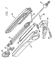
- FIG. 7 is an exploded view of a preferred embodiment of the stent delivery mechanism shown in FIG. 2 .
- FIG. 8 is a cross-sectional view of a second embodiment of the stent delivery mechanism of the present invention incorporating a hydraulic mechanism
- FIGS. 9-12 are cross-sectional views illustrating the operation of the embodiment of FIG. 7 ;
- FIG. 13 is a cross-sectional view of a third embodiment of the stent delivery mechanism of the present invention employing a rack and pinion thumb actuated drive system;
- FIG. 14 is a view of the system of FIG. 13 along line 14 - 14 ;
- FIGS. 15 and 16 are cross-sectional views illustrating the operation of the drive system of FIG. 13 ;
- FIG. 17 is a cross-sectional view of a fourth embodiment of the stent delivery mechanism of the present invention employing a power screw drive system
- FIG. 18 is an end plan view illustrating the drive knob and collar configuration of the system of FIG. 17 ;
- FIGS. 19 and 20 are cross-sectional views illustrating the operation of the power screw drive system of FIG. 17 .
- FIG. 1 illustrates the distal end of a catheter 11 having a stent 16 carried within it for implantation into the body of a patient.
- the proximal end of the catheter 11 is connected to any of the delivery mechanisms to be described, and the catheter 11 is of sufficient length to reach the point of implantation of the stent 16 from the introduction point into the body.
- the catheter 11 includes an outer sheath 10 , a middle tube 12 which in the preferred embodiment is formed of a compressed spring, and a flexible (e.g., polyamide) inner tube 14 .
- the outer sheath 10 preferably has an ePTFE liner with a polyether blocked amide plastic (pebax) basecoat with reinforced braid, and an external layer of pebax.
- pebax polyether blocked amide plastic
- a stent 16 for implantation into a patient is carried within the outer sheath 10 .
- the stent 16 includes a nitinol memory metal alloy frame 18 which is formed in a criss-cross pattern which may be laser cut. Most or all of the length of the stent is encapsulated within two layers of ePTFE to form a monolithic body structure 20 , fully enclosing the metallic stent 16 both internally and externally where the cover 20 is present. One or both ends of the stent 16 may be left uncovered as illustrated at 22 and 24 to provide anchoring within the vessel where the stent 16 is to be implanted.
- a radiopaque atraumatic tip 26 is secured to the end of the inner tube 14 of the catheter.
- the atraumatic tip 26 has a rounded end and is gradually sloped to aid in the movement of the catheter through the body vessel.
- the atraumatic tip 26 is radiopaque so that its location may be monitored by appropriate equipment during the surgical procedure.
- the inner tube 14 is hollow so as to accommodate a guide wire, which is commonly placed in the vessel prior to insertion of the catheter, although the invention may employ a solid inner section and be used without a guide wire.
- Inner tube 14 has sufficient kink resistance to engage the vascular anatomy without binding during placement and withdrawal of the delivery system.
- inner tube 14 is of sufficient size and strength to allow saline injections without rupture.
- a generally cup-shaped element 28 is provided within the catheter 11 adjacent the rear end of the stent 16 and is attached to the end of the spring 12 by appropriate means, e.g., the cup element 28 may be plastic wherein the spring 12 is molded into its base, or the cup element 28 may be stainless steel wherein the spring 12 is secured by welding or the like.
- the open end of the cup element 28 serves to compress the end 24 of the stent 16 in order to provide a secure interface between the stent 16 and the spring 12 .
- the element 28 could be formed of a simple disk having either a flat or slightly concave surface for contacting the end 24 of the stent 16 .
- the catheter 11 In order to deploy the stent 16 inside a body vessel during a surgical procedure, the catheter 11 is introduced into the designated vessel via an introducer positioned at the skin of the patient.
- a guide wire may have previously been introduced into the vessel, in which case the catheter 11 is introduced by passing the tip 26 over the end of the guide wire outside of the patient and moving the catheter 11 along the path within the vessel which has been established by the guide wire.
- the position of the catheter 11 is tracked by monitoring the tip 26 by means of a fluoroscope.
- the catheter 11 When the catheter 11 is at the desired location i.e., when the stent 16 is positioned at the location where it is be implanted, the movement of the catheter 11 is halted. The catheter 11 must then be removed, leaving the stent 16 in place at the desired location within the vessel. This is accomplished by initially retracting the outer sheath 10 , i.e., towards the left in FIG. 1 , until it no longer covers the stent 16 .
- the spring 12 is maintained in a fixed position and, in conjunction with the cup element 28 , serves to maintain the stent 16 in its desired position during the retraction of the outer sheath 10 .
- the tip 26 can be pulled back through the stent 16 until the tip 26 abuts the outer sheath 10 .
- the diameter of the tip 26 is slightly greater than the inner diameter of stent 16 when it is inside the outer sheath 10 .
- the stent 16 will expand as it heats up to body temperature as a result of its memory metal characteristics.
- the tip 26 is then pulled through the center of the stent 16 after the stent 16 has expanded following withdrawal of the sheath 10 .
- the catheter 11 can be removed from the vessel of the patient. This retraction procedure ensures that the tip 26 does not get caught on or embedded in any body vessel when being pulled out of the patient.
- the tube spring 12 is maintained stationary during the withdrawal of the outer sheath 10 and serves to keep the stent 16 in its desired location.
- the tube spring 12 is very well suited for this task since it has extremely low compression in a longitudinal direction once it is fully compressed. It is also well suited for the introduction of the catheter 11 into the body vessel, since it is extremely flexible. Alternatively, other materials, such as various plastics materials, could be employed as the middle tube 12 , so long as the compression is low to maintain stent positioning and the necessary flexibility is provided for moving through the vessel.
- the outer sheath 10 In order to properly deploy the stent 16 , the outer sheath 10 must be smoothly retracted while the tube spring 12 maintains its position.
- the present invention provides a number of mechanisms intended to perform this operation with maximum ease of use and minimal stent migration.
- FIG. 2 illustrates a first embodiment of a delivery mechanism for implanting the stent 16 .
- This mechanism is generally in the form of a V-shaped lever device having a housing shell 30 from which the outer sheath 10 extends.
- the sheath 10 is secured to a pawl/sheath hub 32 .
- a spring pawl 34 attached to the hub 32 engages a ratchet 36 which is integrated into the housing shell 30 . Movement of the sheath hub 32 within the housing shell 30 is thus constrained to moving to the right as shown in FIG. 2 .
- the tube spring 12 is secured in a fixed position to a guide wire port 38 .
- the interior of the device may be flushed by means of a flush stop cock 40 .
- a ratchet rail 42 is provided at the bottom of the housing shell 30 and is reciprocal back and forth within the shell 30 .
- the rail 42 includes ratchet teeth 44 on the upper side which engage with the spring pawl 34 and a rack gear 46 on the bottom surface thereof which engages a pinion 48 .
- the pinion 48 is rotated by means of a lever handle 50 which includes a drive gear 52 .
- the lever handle 50 is spring biased by means of a spring 54 to its open position.
- Other types of springs, such as a spring contained within the pivot point 56 of the lever handle could alternatively be employed.
- the handle 50 is in its open position, which forms an angle of approximately twenty-five degrees with the housing shell 30 .
- the drive gear 52 rotates the pinion 48 in a clockwise direction as illustrated by arrow 60 .
- the pinion 48 drives the rail 42 to the right, which in turn drives the sheath hub 32 to the right, thus extracting the outer sheath 10 by an incremental distance illustrated at 62 .
- the incremental distance is approximately 1 cm.
- the handle 50 when the handle 50 is released, the spring action returns it to the open position, thus rotating the pinion 48 counterclockwise and returning the rail 42 to its leftward position.
- the sheath hub 32 is maintained stationary by the ratchet 36 .
- FIG. 6 illustrates the mechanism in which the handle 50 has been operated to move the hub 32 , and therefore the outer sheath 10 , back to its completely rightmost position. In this position (or sooner depending upon the length of the stent) the outer sheath 10 will be completely away from the stent 16 , allowing the stent 16 to expand. As described above, once the stent 16 expands, the inner tube 14 and tip 26 are pulled back through the middle of the stent 16 until the tip 26 is tight against the outer sheath 10 . The entire catheter 11 can then be removed, leaving the stent 16 in place at the desired location.
- FIG. 7 A preferred embodiment of the device shown in FIG. 2 is illustrated by the exploded view in FIG. 7 .
- a left housing assembly 31 and a right housing assembly 33 can be seen.
- An inner catheter assembly 37 is disposed between the housing assemblies 31 and 33 to support the tube spring 12 as well as the spring pawl 34 .
- a strain relief member 51 fits over the end of housing shell 30 to reduce any potential pressure caused in the actuation of the mechanism.
- a safety pin 53 is insertable into the lever handle 50 for additional protection.
- the inner catheter assembly 37 which is coupled to the inner tube 14 , is pulled back away from the housing assemblies 31 and 33 in order to retract the inner tube 14 far enough so that tip 26 is snuggly against the outer sheath 10 .
- the catheter 11 including the outer sheath 10 , the inner tube 14 and the tip 26 can then be removed from the body. Retraction of the catheter 11 in this manner ensures that the tip 26 can not get caught on anything outside of the body or inside the delivery mechanism.
- the gear mechanism including the lever gear 52 , pinion 48 and rack 46 is designed to provide a mechanical advantage of approximately 4:1.
- the mechanical advantage along with the rotating pinion configuration provides very smooth and linear operation with minimal fly back during the return stroke.
- the lever handle configuration is extremely convenient, as it can be easily operated in almost any rotational orientation. This is important due to the fact that when a catheter is introduced into the patient, it is often necessary to rotate the catheter in order for it to most easily follow the desired path through the vessel to the stent location. Therefore, the final orientation when the stent is to be deployed is variable.
- the configuration of the V-shaped lever handle mechanism enables a simple gripping action to be applied, and is easily gripped by the surgeon regardless of its final orientation.
- FIG. 8 A second embodiment of the stent delivery mechanism is illustrated in FIG. 8 .
- This delivery mechanism employs a hydraulic system to achieve extremely smooth operation.
- a housing 62 defines a reservoir chamber 64 within which is carried a piston 66 .
- the outer sheath 10 is connected to the piston 66 to be moved therewith.
- a V-cup seal 68 prevents leakage of the hydraulic fluid carried within the housing.
- a piston displacement chamber 70 is defined between the piston 66 and the opening through which the sheath 10 exits.
- Conduits 72 and 74 are coupled to opposite ends of the piston housing 62 .
- Directional check valves 76 and 78 are contained within the conduits 72 and 74 , respectively.
- a drive plunger 80 is contained within a plunger housing 82 .
- Hydraulic fluid such as saline solution, is provided through a port 84 .
- FIGS. 9-12 The operation of the hydraulic mechanism will be described with reference to FIGS. 9-12 .
- the reservoir 64 is filled with fluid and the system is ready for operation.
- the plunger 80 is pulled rearward and transfers saline from the reservoir 64 through the conduit 72 via valve 76 .
- the valve 76 is open in this state and the valve 78 is closed.
- the plunger 80 is pressed inward to open the valve 78 and move fluid through the conduit 74 into the piston chamber 70 , thus moving the piston 66 to the right by a fixed amount and, in turn, retracting the outer sheath 10 from the stent.
- one stroke of the plunger 80 provides approximately 1 cm of travel of the piston 66 .
- the plunger and piston are sized to provide a mechanical advantage of approximately 4:1.
- a lever or trigger mechanism could be employed to actuate the plunger 80 .
- Such mechanism would include a spring return or the like to bias the plunger to the extended position.
- the use of a lever mechanism in which case the plunger orientation would be reversed and a lever handle coupled to it) would allow grip pressure to be utilized as opposed to finger or thumb pressure.
- FIGS. 13-16 a third embodiment of the invention will be described.
- This embodiment employs a rack and pinion mechanism actuated by means of a thumb knob.
- the device includes a housing 82 within which is carried a rack 84 , movable from left to right as illustrated in FIGS. 15 and 16 .
- the rack 84 interacts with a rack drive gear 86 coupled to a reduction drive gear 88 , which in turn is driven by a knob 90 having a gear 92 .
- the outer sheath 10 is coupled to the rack 84 to be movable therewith.
- FIG. 14 is a cross-sectional view of FIG. 13 along line 14 - 14 , showing a different perspective of knob 90 in relation to housing 82 .
- the knob 90 is rotated counterclockwise as illustrated in FIG. 15 , causing the gear 92 to move in the same direction.
- This action causes the reduction drive gear 88 and the rack drive gear 86 to move in a clockwise position, which in turn causes the rack 84 to retract within the housing by a distance of approximately 1 cm per revolution of the knob as indicated at 94 .
- the mechanical advantage is controlled by appropriate sizing of the gears which drive the rack 84 . After a sufficient number of rotations, the rack 84 will be fully retracted, as illustrated in FIG. 16 and the outer sheath 10 will be completely removed from the stent 16 so that the catheter 11 can be removed from the patient as described above.
- FIGS. 17-20 a fourth embodiment of the delivery system will be described.
- a power screw drive system is employed.
- a drive knob 96 is carried within a collar 98 of a housing 100 .
- the drive knob 96 is fixed to a power nut 102 having a threaded interior surface which mates with the threaded surface of a power screw 104 which is slidably carried within the housing 100 .
- the outer sheath 10 is coupled to the power screw 104 to move in conjunction therewith.
- the power nut 102 rotates and drives the power screw 104 to the right as shown in the FIGS. 19 and 20 .
- FIG. 18 is an end plan view, illustrating the drive knob 96 within the collar 98 .
- the mechanical advantage of this fourth embodiment is determined by the pitch of the power screw 104 and the size of the knob 96 .
- a single rotation of the knob 96 achieves a movement of the power screw 104 of approximately 1 cm, as indicated at 106 .
- the high mechanical advantage provided by the configuration facilitates smooth retraction of the outer sheath 10 .
- the power screw 104 will be fully retracted, as illustrated in FIG. 20 , and the outer sheath 10 will be completely withdrawn from the stent 16 .
- the catheter 11 can then be removed as described above.
- each of the disclosed systems provides a significant mechanical advantage which facilitates smooth retraction of the outer sheath 10 which covers the stent 16 . This minimizes migration of the stent 10 during sheath retraction, thus ensuring that the stent 16 will remain in its desired location.
- various configurations are provided which are operable in numerous orientations, thus providing convenient and simple use during surgery.
Abstract
Description
Claims (19)
Priority Applications (2)
| Application Number | Priority Date | Filing Date | Title |
|---|---|---|---|
| US11/581,645 US8852266B2 (en) | 1998-09-30 | 2006-10-16 | Delivery mechanism for implantable stent |
| US14/507,778 US20150025615A1 (en) | 1998-09-30 | 2014-10-06 | Delivery Mechanism for Implantable Stent |
Applications Claiming Priority (4)
| Application Number | Priority Date | Filing Date | Title |
|---|---|---|---|
| US10249898P | 1998-09-30 | 1998-09-30 | |
| US09/409,210 US6514261B1 (en) | 1998-09-30 | 1999-09-30 | Delivery mechanism for implantable stent |
| US10/357,985 US7122050B2 (en) | 1998-09-30 | 2003-02-04 | Delivery mechanism for implantable stent |
| US11/581,645 US8852266B2 (en) | 1998-09-30 | 2006-10-16 | Delivery mechanism for implantable stent |
Related Parent Applications (1)
| Application Number | Title | Priority Date | Filing Date |
|---|---|---|---|
| US10/357,985 Continuation US7122050B2 (en) | 1998-09-30 | 2003-02-04 | Delivery mechanism for implantable stent |
Related Child Applications (1)
| Application Number | Title | Priority Date | Filing Date |
|---|---|---|---|
| US14/507,778 Continuation US20150025615A1 (en) | 1998-09-30 | 2014-10-06 | Delivery Mechanism for Implantable Stent |
Publications (2)
| Publication Number | Publication Date |
|---|---|
| US20070032860A1 US20070032860A1 (en) | 2007-02-08 |
| US8852266B2 true US8852266B2 (en) | 2014-10-07 |
Family
ID=22290170
Family Applications (4)
| Application Number | Title | Priority Date | Filing Date |
|---|---|---|---|
| US09/409,210 Expired - Lifetime US6514261B1 (en) | 1998-09-30 | 1999-09-30 | Delivery mechanism for implantable stent |
| US10/357,985 Expired - Lifetime US7122050B2 (en) | 1998-09-30 | 2003-02-04 | Delivery mechanism for implantable stent |
| US11/581,645 Expired - Fee Related US8852266B2 (en) | 1998-09-30 | 2006-10-16 | Delivery mechanism for implantable stent |
| US14/507,778 Abandoned US20150025615A1 (en) | 1998-09-30 | 2014-10-06 | Delivery Mechanism for Implantable Stent |
Family Applications Before (2)
| Application Number | Title | Priority Date | Filing Date |
|---|---|---|---|
| US09/409,210 Expired - Lifetime US6514261B1 (en) | 1998-09-30 | 1999-09-30 | Delivery mechanism for implantable stent |
| US10/357,985 Expired - Lifetime US7122050B2 (en) | 1998-09-30 | 2003-02-04 | Delivery mechanism for implantable stent |
Family Applications After (1)
| Application Number | Title | Priority Date | Filing Date |
|---|---|---|---|
| US14/507,778 Abandoned US20150025615A1 (en) | 1998-09-30 | 2014-10-06 | Delivery Mechanism for Implantable Stent |
Country Status (8)
| Country | Link |
|---|---|
| US (4) | US6514261B1 (en) |
| EP (3) | EP1447057A1 (en) |
| JP (1) | JP2002525168A (en) |
| CA (1) | CA2345686C (en) |
| DE (1) | DE69922976T2 (en) |
| ES (1) | ES2237168T3 (en) |
| MX (1) | MXPA01003283A (en) |
| WO (1) | WO2000018330A1 (en) |
Cited By (16)
| Publication number | Priority date | Publication date | Assignee | Title |
|---|---|---|---|---|
| US9554940B2 (en) | 2012-03-26 | 2017-01-31 | Glaukos Corporation | System and method for delivering multiple ocular implants |
| US9561131B2 (en) | 2001-08-28 | 2017-02-07 | Glaukos Corporation | Implant delivery system and methods thereof for treating ocular disorders |
| US9572963B2 (en) | 2001-04-07 | 2017-02-21 | Glaukos Corporation | Ocular disorder treatment methods and systems |
| US9592151B2 (en) | 2013-03-15 | 2017-03-14 | Glaukos Corporation | Systems and methods for delivering an ocular implant to the suprachoroidal space within an eye |
| US9597230B2 (en) | 2002-04-08 | 2017-03-21 | Glaukos Corporation | Devices and methods for glaucoma treatment |
| US9962290B2 (en) | 2006-11-10 | 2018-05-08 | Glaukos Corporation | Uveoscleral shunt and methods for implanting same |
| US9993368B2 (en) | 2000-04-14 | 2018-06-12 | Glaukos Corporation | System and method for treating an ocular disorder |
| WO2018124924A1 (en) * | 2016-12-30 | 2018-07-05 | Общество с ограниченной ответственностью "СЕВЕН САНС" | Device and method for safely positioning a coronary stent in the coronary arteries |
| USD846738S1 (en) | 2017-10-27 | 2019-04-23 | Glaukos Corporation | Implant delivery apparatus |
| US10441449B1 (en) | 2018-05-30 | 2019-10-15 | Vesper Medical, Inc. | Rotary handle stent delivery system and method |
| US10449073B1 (en) | 2018-09-18 | 2019-10-22 | Vesper Medical, Inc. | Rotary handle stent delivery system and method |
| US11083606B2 (en) | 2017-12-05 | 2021-08-10 | Cook Medical Technologies Llc | Endograft delivery device assembly |
| US11116625B2 (en) | 2017-09-28 | 2021-09-14 | Glaukos Corporation | Apparatus and method for controlling placement of intraocular implants |
| US11166833B2 (en) | 2019-04-30 | 2021-11-09 | Cook Medical Technologies Llc | Line pull assembly for a prosthetic delivery device |
| US11219541B2 (en) | 2020-05-21 | 2022-01-11 | Vesper Medical, Inc. | Wheel lock for thumbwheel actuated device |
| US11376040B2 (en) | 2017-10-06 | 2022-07-05 | Glaukos Corporation | Systems and methods for delivering multiple ocular implants |
Families Citing this family (312)
| Publication number | Priority date | Publication date | Assignee | Title |
|---|---|---|---|---|
| US7491232B2 (en) | 1998-09-18 | 2009-02-17 | Aptus Endosystems, Inc. | Catheter-based fastener implantation apparatus and methods with implantation force resolution |
| EP1447057A1 (en) | 1998-09-30 | 2004-08-18 | Bard Peripheral Vascular, Inc. | Delivery mechanism for implantable stent |
| US7018401B1 (en) | 1999-02-01 | 2006-03-28 | Board Of Regents, The University Of Texas System | Woven intravascular devices and methods for making the same and apparatus for delivery of the same |
| US6726712B1 (en) * | 1999-05-14 | 2004-04-27 | Boston Scientific Scimed | Prosthesis deployment device with translucent distal end |
| US8632583B2 (en) | 2011-05-09 | 2014-01-21 | Palmaz Scientific, Inc. | Implantable medical device having enhanced endothelial migration features and methods of making the same |
| DE60115821T2 (en) * | 2000-10-13 | 2006-08-31 | Medtronic AVE, Inc., Santa Rosa | Hydraulic stent delivery system |
| US6884257B1 (en) * | 2000-11-28 | 2005-04-26 | Advanced Cardiovascular Systems, Inc. | Stent delivery system with adjustable length balloon |
| US6699274B2 (en) * | 2001-01-22 | 2004-03-02 | Scimed Life Systems, Inc. | Stent delivery system and method of manufacturing same |
| US6743210B2 (en) * | 2001-02-15 | 2004-06-01 | Scimed Life Systems, Inc. | Stent delivery catheter positioning device |
| US6660031B2 (en) | 2001-04-11 | 2003-12-09 | Scimed Life Systems, Inc. | Multi-length delivery system |
| US6770080B2 (en) | 2001-04-26 | 2004-08-03 | Fenestra Medical, Inc. | Mechanically registered videoscopic myringotomy/tympanostomy tube placement system |
| GB0110551D0 (en) | 2001-04-30 | 2001-06-20 | Angiomed Ag | Self-expanding stent delivery service |
| US20050021123A1 (en) | 2001-04-30 | 2005-01-27 | Jurgen Dorn | Variable speed self-expanding stent delivery system and luer locking connector |
| US6679909B2 (en) * | 2001-07-31 | 2004-01-20 | Advanced Cardiovascular Systems, Inc. | Rapid exchange delivery system for self-expanding stent |
| DE10148185B4 (en) | 2001-09-28 | 2005-08-11 | Alveolus, Inc. | Instrument for implanting vascular prostheses |
| US6939352B2 (en) | 2001-10-12 | 2005-09-06 | Cordis Corporation | Handle deployment mechanism for medical device and method |
| US6866669B2 (en) | 2001-10-12 | 2005-03-15 | Cordis Corporation | Locking handle deployment mechanism for medical device and method |
| US8231639B2 (en) * | 2001-11-28 | 2012-07-31 | Aptus Endosystems, Inc. | Systems and methods for attaching a prosthesis within a body lumen or hollow organ |
| US20050177180A1 (en) * | 2001-11-28 | 2005-08-11 | Aptus Endosystems, Inc. | Devices, systems, and methods for supporting tissue and/or structures within a hollow body organ |
| US20110087320A1 (en) * | 2001-11-28 | 2011-04-14 | Aptus Endosystems, Inc. | Devices, Systems, and Methods for Prosthesis Delivery and Implantation, Including a Prosthesis Assembly |
| CN100479786C (en) * | 2001-11-28 | 2009-04-22 | 阿普特斯内系统公司 | Endovascular aneurysm repair system |
| US7147657B2 (en) * | 2003-10-23 | 2006-12-12 | Aptus Endosystems, Inc. | Prosthesis delivery systems and methods |
| US20090099650A1 (en) * | 2001-11-28 | 2009-04-16 | Lee Bolduc | Devices, systems, and methods for endovascular staple and/or prosthesis delivery and implantation |
| US9320503B2 (en) | 2001-11-28 | 2016-04-26 | Medtronic Vascular, Inc. | Devices, system, and methods for guiding an operative tool into an interior body region |
| US20070073389A1 (en) * | 2001-11-28 | 2007-03-29 | Aptus Endosystems, Inc. | Endovascular aneurysm devices, systems, and methods |
| US7052511B2 (en) | 2002-04-04 | 2006-05-30 | Scimed Life Systems, Inc. | Delivery system and method for deployment of foreshortening endoluminal devices |
| US6911039B2 (en) | 2002-04-23 | 2005-06-28 | Medtronic Vascular, Inc. | Integrated mechanical handle with quick slide mechanism |
| US7105016B2 (en) | 2002-04-23 | 2006-09-12 | Medtronic Vascular, Inc. | Integrated mechanical handle with quick slide mechanism |
| EP1524942B1 (en) | 2002-07-26 | 2008-09-10 | Emphasys Medical, Inc. | Bronchial flow control devices with membrane seal |
| EP1388328A1 (en) * | 2002-08-07 | 2004-02-11 | Abbott Laboratories Vascular Enterprises Limited | Apparatus for delivering and deployment of an expandable stent within a blood vessel |
| US8268340B2 (en) | 2002-09-26 | 2012-09-18 | Advanced Bio Prosthetic Surfaces, Ltd. | Implantable materials having engineered surfaces and method of making same |
| US8679517B2 (en) | 2002-09-26 | 2014-03-25 | Palmaz Scientific, Inc. | Implantable materials having engineered surfaces made by vacuum deposition and method of making same |
| EP1551569B1 (en) | 2002-09-26 | 2017-05-10 | Advanced Bio Prosthetic Surfaces, Ltd. | Implantable materials having engineered surfaces and method of making same |
| US20040093056A1 (en) | 2002-10-26 | 2004-05-13 | Johnson Lianw M. | Medical appliance delivery apparatus and method of use |
| JP2004181230A (en) | 2002-11-20 | 2004-07-02 | Olympus Corp | Stent delivery system |
| WO2004049974A2 (en) * | 2002-11-27 | 2004-06-17 | Emphasys Medical, Inc. | Delivery method and device for implantable bronchial isolation devices |
| JP2006518625A (en) * | 2003-02-14 | 2006-08-17 | サルヴィアック・リミテッド | Stent delivery and placement system |
| ES2346059T3 (en) | 2003-03-26 | 2010-10-08 | Biosensors International Group Ltd. | IMPLANT SUPPLY CATHETER WITH ELECTROLYTICALLY EROSIONABLE JOINTS. |
| DE602004018908D1 (en) * | 2003-03-31 | 2009-02-26 | Memry Corp | MEDICAL DEVICES WITH MEDICAMENT ELUTION PROPERTIES AND METHOD OF PREPARATION THEREOF |
| US7637934B2 (en) * | 2003-03-31 | 2009-12-29 | Merit Medical Systems, Inc. | Medical appliance optical delivery and deployment apparatus and method |
| US7604660B2 (en) | 2003-05-01 | 2009-10-20 | Merit Medical Systems, Inc. | Bifurcated medical appliance delivery apparatus and method |
| GB0310715D0 (en) | 2003-05-09 | 2003-06-11 | Angiomed Ag | Strain management in stent delivery system |
| US20050010138A1 (en) * | 2003-07-11 | 2005-01-13 | Mangiardi Eric K. | Lumen-measuring devices and method |
| US20080033570A1 (en) * | 2003-08-01 | 2008-02-07 | Blitz Benjamin T | Prostatic stent placement device |
| WO2005013855A2 (en) * | 2003-08-01 | 2005-02-17 | Cook Urological, Incorporated | Implant delivery device |
| US7757691B2 (en) * | 2003-08-07 | 2010-07-20 | Merit Medical Systems, Inc. | Therapeutic medical appliance delivery and method of use |
| US7993384B2 (en) * | 2003-09-12 | 2011-08-09 | Abbott Cardiovascular Systems Inc. | Delivery system for medical devices |
| US7758625B2 (en) | 2003-09-12 | 2010-07-20 | Abbott Vascular Solutions Inc. | Delivery system for medical devices |
| US7967829B2 (en) | 2003-10-09 | 2011-06-28 | Boston Scientific Scimed, Inc. | Medical device delivery system |
| US7867271B2 (en) | 2003-11-20 | 2011-01-11 | Advanced Cardiovascular Systems, Inc. | Rapid-exchange delivery systems for self-expanding stents |
| US7481793B2 (en) * | 2003-12-10 | 2009-01-27 | Boston Scientic Scimed, Inc. | Modular steerable sheath catheters |
| US7162030B2 (en) * | 2003-12-23 | 2007-01-09 | Nokia Corporation | Communication device with rotating housing |
| US7887574B2 (en) * | 2003-12-23 | 2011-02-15 | Scimed Life Systems, Inc. | Stent delivery catheter |
| ATE473707T1 (en) * | 2004-01-08 | 2010-07-15 | Merit Medical Systems Inc | HANDLE FOR AN IMPLANT DEPOSIT SYSTEM AND METHOD OF USE |
| US7468070B2 (en) | 2004-01-23 | 2008-12-23 | Boston Scientific Scimed, Inc. | Stent delivery catheter |
| JP4504696B2 (en) * | 2004-02-03 | 2010-07-14 | オリンパス株式会社 | Endoscopic treatment tool, endoscope, and endoscope treatment system |
| US7225518B2 (en) * | 2004-02-23 | 2007-06-05 | Boston Scientific Scimed, Inc. | Apparatus for crimping a stent assembly |
| US20060206200A1 (en) * | 2004-05-25 | 2006-09-14 | Chestnut Medical Technologies, Inc. | Flexible vascular occluding device |
| WO2010120926A1 (en) | 2004-05-25 | 2010-10-21 | Chestnut Medical Technologies, Inc. | Vascular stenting for aneurysms |
| US8267985B2 (en) | 2005-05-25 | 2012-09-18 | Tyco Healthcare Group Lp | System and method for delivering and deploying an occluding device within a vessel |
| US8617234B2 (en) * | 2004-05-25 | 2013-12-31 | Covidien Lp | Flexible vascular occluding device |
| JP2008502378A (en) | 2004-05-25 | 2008-01-31 | チェストナット メディカル テクノロジーズ インコーポレイテッド | Flexible vascular closure device |
| US8628564B2 (en) | 2004-05-25 | 2014-01-14 | Covidien Lp | Methods and apparatus for luminal stenting |
| US20050273151A1 (en) * | 2004-06-04 | 2005-12-08 | John Fulkerson | Stent delivery system |
| US7747333B2 (en) * | 2004-08-16 | 2010-06-29 | Cardiac Pacemakers, Inc. | Lead assembly and methods including a push tube |
| US8277457B1 (en) | 2004-12-09 | 2012-10-02 | Greatbatch Medical S.A. | Orthopaedic inserter using a collet mechanism |
| DE102005003632A1 (en) | 2005-01-20 | 2006-08-17 | Fraunhofer-Gesellschaft zur Förderung der angewandten Forschung e.V. | Catheter for the transvascular implantation of heart valve prostheses |
| US8372097B2 (en) * | 2005-03-04 | 2013-02-12 | Koven Technology Canada Inc. | Valvulotome |
| US7740652B2 (en) | 2005-03-30 | 2010-06-22 | Boston Scientific Scimed, Inc. | Catheter |
| US20060253193A1 (en) * | 2005-05-03 | 2006-11-09 | Lichtenstein Samuel V | Mechanical means for controlling blood pressure |
| US20070118207A1 (en) * | 2005-05-04 | 2007-05-24 | Aga Medical Corporation | System for controlled delivery of stents and grafts |
| US20060253184A1 (en) * | 2005-05-04 | 2006-11-09 | Kurt Amplatz | System for the controlled delivery of stents and grafts |
| US8652193B2 (en) | 2005-05-09 | 2014-02-18 | Angiomed Gmbh & Co. Medizintechnik Kg | Implant delivery device |
| US8986360B2 (en) * | 2005-05-13 | 2015-03-24 | Merit Medical Systems, Inc. | Delivery device with shortened inner tube and associated method |
| US8273101B2 (en) | 2005-05-25 | 2012-09-25 | Tyco Healthcare Group Lp | System and method for delivering and deploying an occluding device within a vessel |
| AU2005332044B2 (en) | 2005-05-25 | 2012-01-19 | Covidien Lp | System and method for delivering and deploying and occluding device within a vessel |
| ATE526911T1 (en) | 2005-08-17 | 2011-10-15 | Bard Inc C R | VARIABLE SPEED STENT DELIVERY SYSTEM |
| US8167932B2 (en) * | 2005-10-18 | 2012-05-01 | Edwards Lifesciences Corporation | Heart valve delivery system with valve catheter |
| CN101466316B (en) | 2005-10-20 | 2012-06-27 | 阿普特斯内系统公司 | Devices systems and methods for prosthesis delivery and implantation including the use of a fastener tool |
| DE102005051469B4 (en) * | 2005-10-21 | 2011-07-28 | JOTEC GmbH, 72379 | Device for introducing a self-expanding stent into a body vessel |
| US20070123904A1 (en) * | 2005-10-31 | 2007-05-31 | Depuy Spine, Inc. | Distraction instrument and method for distracting an intervertebral site |
| US20070100414A1 (en) | 2005-11-02 | 2007-05-03 | Cardiomind, Inc. | Indirect-release electrolytic implant delivery systems |
| US20070162127A1 (en) * | 2005-12-08 | 2007-07-12 | Sdgi Holdings, Inc. | Instruments and techniques for delivering non-rigid implant members in surgical procedures |
| JP5181211B2 (en) * | 2005-12-23 | 2013-04-10 | クック・メディカル・テクノロジーズ・リミテッド・ライアビリティ・カンパニー | Trigger wire release mechanism and introducer for prosthesis including the same |
| CA2936205C (en) | 2006-01-13 | 2018-08-21 | C.R. Bard, Inc. | Stent delivery system |
| US11026822B2 (en) | 2006-01-13 | 2021-06-08 | C. R. Bard, Inc. | Stent delivery system |
| US20070173924A1 (en) * | 2006-01-23 | 2007-07-26 | Daniel Gelbart | Axially-elongating stent and method of deployment |
| DE102006004123A1 (en) * | 2006-01-25 | 2007-08-02 | Jotec Gmbh | Feed system for the insertion of expandable stents into cardiac arteries uses a hand held grip |
| US8518098B2 (en) | 2006-02-21 | 2013-08-27 | Cook Medical Technologies Llc | Split sheath deployment system |
| WO2007100556A1 (en) | 2006-02-22 | 2007-09-07 | Ev3 Inc. | Embolic protection systems having radiopaque filter mesh |
| US20070219617A1 (en) * | 2006-03-17 | 2007-09-20 | Sean Saint | Handle for Long Self Expanding Stent |
| US20070225659A1 (en) * | 2006-03-21 | 2007-09-27 | Cook Incorporated | Introducer sheath having frangible tip |
| US8070768B2 (en) | 2006-04-19 | 2011-12-06 | Vibrynt, Inc. | Devices and methods for treatment of obesity |
| DE102007020484A1 (en) | 2006-05-01 | 2007-12-13 | Precimed S.A. | Insertion instrument for minimally invasive joint surgery with exchangeable thread |
| US20070287879A1 (en) * | 2006-06-13 | 2007-12-13 | Daniel Gelbart | Mechanical means for controlling blood pressure |
| US8118853B2 (en) * | 2006-06-19 | 2012-02-21 | Cook Medical Technologies Llc | Prosthesis delivery and deployment device |
| GB0615658D0 (en) | 2006-08-07 | 2006-09-13 | Angiomed Ag | Hand-held actuator device |
| MX2009004292A (en) | 2006-10-22 | 2009-08-12 | Idev Technologies Inc | Devices and methods for stent advancement. |
| EP3329882B1 (en) | 2006-10-22 | 2023-09-20 | IDEV Technologies, INC. | Methods for securing strand ends and the resulting devices |
| DE102006054250A1 (en) * | 2006-11-17 | 2008-05-21 | Biotronik Vi Patent Ag | Handling device for a medical catheter has an outer sleeve and an inner element sliding in the outer sleeve to protrude from the outer sleeve at the catheter's proximal end |
| DE102007010305A1 (en) | 2007-02-22 | 2008-08-28 | Jotec Gmbh | Device for releasing a self-expanding stent into a body vessel |
| US7896915B2 (en) | 2007-04-13 | 2011-03-01 | Jenavalve Technology, Inc. | Medical device for treating a heart valve insufficiency |
| US9387124B2 (en) | 2007-04-19 | 2016-07-12 | Tusker Medical, Inc. | Disposable iontophoresis system and tympanic membrane pain inhibition method |
| DE102007022122B4 (en) | 2007-05-11 | 2019-07-11 | Deutsches Zentrum für Luft- und Raumfahrt e.V. | Gripping device for a surgery robot arrangement |
| US20080294230A1 (en) * | 2007-05-24 | 2008-11-27 | Cook Incorporated | Apparatus and methods for deploying self-expanding stents |
| US20090018493A1 (en) * | 2007-07-10 | 2009-01-15 | Ash Stephen R | Implantable catheter assembly |
| GB0713497D0 (en) | 2007-07-11 | 2007-08-22 | Angiomed Ag | Device for catheter sheath retraction |
| US9149379B2 (en) * | 2007-07-16 | 2015-10-06 | Cook Medical Technologies Llc | Delivery device |
| US9119742B2 (en) * | 2007-07-16 | 2015-09-01 | Cook Medical Technologies Llc | Prosthesis delivery and deployment device |
| GB0718187D0 (en) | 2007-09-18 | 2007-10-31 | Angiomed Ag | Radially expansible stent |
| US20090105713A1 (en) * | 2007-10-09 | 2009-04-23 | William Cook, Europe Aps | Deployment handle for an implant deployment device |
| US20090099638A1 (en) * | 2007-10-11 | 2009-04-16 | Med Institute, Inc. | Motorized deployment system |
| US20090275971A1 (en) * | 2007-10-30 | 2009-11-05 | Boston Scientific Scimed, Inc. | Energy activated preloaded detachment mechanisms for implantable devices |
| US8075607B2 (en) * | 2007-12-27 | 2011-12-13 | Cook Medical Technologies Llc | Control handle |
| US20090210046A1 (en) * | 2008-02-20 | 2009-08-20 | Abbott Laboratories | Handle assembly for a delivery system |
| US9044318B2 (en) | 2008-02-26 | 2015-06-02 | Jenavalve Technology Gmbh | Stent for the positioning and anchoring of a valvular prosthesis |
| WO2011104269A1 (en) | 2008-02-26 | 2011-09-01 | Jenavalve Technology Inc. | Stent for the positioning and anchoring of a valvular prosthesis in an implantation site in the heart of a patient |
| US8313525B2 (en) * | 2008-03-18 | 2012-11-20 | Medtronic Ventor Technologies, Ltd. | Valve suturing and implantation procedures |
| DE102008021060A1 (en) | 2008-04-26 | 2009-10-29 | Biotronik Vi Patent Ag | An insertion device with a release device for releasing an article carried by a catheter and a release device of an insertion device |
| US9675482B2 (en) * | 2008-05-13 | 2017-06-13 | Covidien Lp | Braid implant delivery systems |
| US20090287145A1 (en) * | 2008-05-15 | 2009-11-19 | Altura Interventional, Inc. | Devices and methods for treatment of abdominal aortic aneurysms |
| US8333003B2 (en) | 2008-05-19 | 2012-12-18 | Boston Scientific Scimed, Inc. | Bifurcation stent crimping systems and methods |
| US10285747B2 (en) * | 2008-06-18 | 2019-05-14 | Alphatec Spine, Inc. | Implant deployment system and methods of use |
| US8070694B2 (en) * | 2008-07-14 | 2011-12-06 | Medtronic Vascular, Inc. | Fiber based medical devices and aspiration catheters |
| US8840602B2 (en) | 2008-07-31 | 2014-09-23 | Acclarent, Inc. | Systems and methods for anesthetizing ear tissue |
| US8452392B2 (en) | 2008-07-31 | 2013-05-28 | Acclarent, Inc. | Systems and methods for anesthetizing ear tissue |
| US7976574B2 (en) * | 2008-08-08 | 2011-07-12 | Advanced Cardiovascular Systems, Inc. | Delivery system with variable delivery rate for deploying a medical device |
| EP2313032B1 (en) * | 2008-08-19 | 2020-12-23 | Merit Medical Systems, Inc. | Delivery device with a protective member |
| DE102008048533A1 (en) | 2008-09-16 | 2010-03-25 | Jotec Gmbh | Delivery system for discontinuing catheter-based stent devices |
| US8597454B2 (en) | 2008-09-23 | 2013-12-03 | Cook Medical Technologies Llc | Catheter tip assembly |
| EP2349086B1 (en) | 2008-10-16 | 2017-03-22 | Medtronic Vascular, Inc. | Devices and systems for endovascular staple and/or prosthesis delivery and implantation |
| CA2747748C (en) * | 2008-12-30 | 2014-05-20 | Wilson-Cook Medical Inc. | Delivery device |
| US8876807B2 (en) | 2009-01-19 | 2014-11-04 | W. L. Gore & Associates, Inc. | Forced deployment sequence |
| US8858610B2 (en) | 2009-01-19 | 2014-10-14 | W. L. Gore & Associates, Inc. | Forced deployment sequence |
| US8398650B1 (en) | 2009-01-27 | 2013-03-19 | Greatbatch Medical S.A. | Offset cup impactor with an expandable dome for double mobility implants |
| US9301863B2 (en) * | 2009-03-10 | 2016-04-05 | Medtronic Vascular, Inc. | Prosthesis delivery apparatus and methods |
| US8858613B2 (en) | 2010-09-20 | 2014-10-14 | Altura Medical, Inc. | Stent graft delivery systems and associated methods |
| US9539146B2 (en) | 2009-07-15 | 2017-01-10 | Tusker Medical, Inc. | Trigger assembly for tympanostomy tube delivery device |
| US9770366B2 (en) | 2009-07-15 | 2017-09-26 | Tusker Medical, Inc. | Tympanic membrane pressure equalization tube delivery system |
| CA2782385A1 (en) | 2009-12-01 | 2011-06-09 | Altura Medical, Inc. | Modular endograft devices and associated systems and methods |
| AU2011210747B2 (en) * | 2010-01-29 | 2013-06-13 | Cook Medical Technologies Llc | Mechanically expandable delivery and dilation systems |
| US8663305B2 (en) | 2010-04-20 | 2014-03-04 | Medtronic Vascular, Inc. | Retraction mechanism and method for graft cover retraction |
| US8747448B2 (en) | 2010-04-30 | 2014-06-10 | Medtronic Vascular, Inc. | Stent graft delivery system |
| US8623064B2 (en) | 2010-04-30 | 2014-01-07 | Medtronic Vascular, Inc. | Stent graft delivery system and method of use |
| JP2013526388A (en) | 2010-05-25 | 2013-06-24 | イエナバルブ テクノロジー インク | Artificial heart valve, and transcatheter delivery prosthesis comprising an artificial heart valve and a stent |
| US8798721B2 (en) * | 2010-05-26 | 2014-08-05 | Dib Ultrasound Catheter, Llc | System and method for visualizing catheter placement in a vasculature |
| DE202010007592U1 (en) | 2010-05-27 | 2010-10-14 | Idev Technologies, Inc. | Stent delivery system with slider assembly |
| US9023095B2 (en) | 2010-05-27 | 2015-05-05 | Idev Technologies, Inc. | Stent delivery system with pusher assembly |
| AU2011270933A1 (en) | 2010-06-24 | 2013-01-31 | Cordis Corporation | Apparatus for and method of pulling a tensile member from a medical device |
| AU2011279948B2 (en) * | 2010-07-21 | 2014-08-07 | Cook Medical Tecnologies Llc | Control system for a stent delivery system |
| PL2598086T3 (en) | 2010-07-30 | 2017-06-30 | Cook Medical Technologies Llc | Controlled release and recapture prosthetic deployment device |
| US9326872B2 (en) | 2010-08-17 | 2016-05-03 | W. L. Gore & Associates, Inc. | Forced deployment sequence handle assembly with independent actuating mechanism |
| JP5891228B2 (en) | 2010-08-24 | 2016-03-22 | セント・ジュード・メディカル,インコーポレイテッド | Staged deployment apparatus and method for a transcatheter heart valve delivery system |
| US8961528B2 (en) | 2010-08-27 | 2015-02-24 | Greatbatch Medical S.A. | Offset cup impactor with a grasping plate for double mobility implants |
| AU2011296277B2 (en) | 2010-09-01 | 2014-10-23 | Medtronic Inc. | Single handed deployment handle |
| US9463269B2 (en) | 2010-09-10 | 2016-10-11 | W. L. Gore & Associates, Inc. | Anastomotic devices and methods |
| JP2013541366A (en) | 2010-09-17 | 2013-11-14 | セント・ジュード・メディカル,カーディオロジー・ディヴィジョン,インコーポレイテッド | Staged deployment apparatus and method for transcatheter heart valve delivery |
| GB201017834D0 (en) | 2010-10-21 | 2010-12-01 | Angiomed Ag | System to deliver a bodily implant |
| EP2640324B1 (en) | 2010-11-17 | 2015-02-18 | Boston Scientific Scimed, Inc. | Stent delivery system |
| CN103298433B (en) | 2010-11-17 | 2016-03-16 | 波士顿科学西美德公司 | Stent delivery system and the Lock Part for using together with stent delivery system |
| EP3375413A1 (en) | 2010-11-17 | 2018-09-19 | Boston Scientific Scimed, Inc. | Stent delivery system |
| EP2648654B1 (en) | 2010-12-07 | 2024-02-14 | Merit Medical Systems, Inc. | Stent delivery systems |
| WO2012096687A1 (en) | 2011-01-14 | 2012-07-19 | Idev Technologies, Inc | Stent delivery system with pusher assembly |
| US8585709B2 (en) | 2011-01-17 | 2013-11-19 | Greatbatch Medical S.A. | Straight cup impactor with lever arm |
| US9119731B2 (en) | 2011-01-17 | 2015-09-01 | Greatbach Medical S.A. | Straight cup impactor |
| US9486348B2 (en) | 2011-02-01 | 2016-11-08 | S. Jude Medical, Cardiology Division, Inc. | Vascular delivery system and method |
| US9717593B2 (en) | 2011-02-01 | 2017-08-01 | St. Jude Medical, Cardiology Division, Inc. | Leaflet suturing to commissure points for prosthetic heart valve |
| CN103228234B (en) | 2011-02-24 | 2016-05-04 | 泰尔茂株式会社 | Stent delivery system |
| WO2012117749A1 (en) * | 2011-03-03 | 2012-09-07 | テルモ株式会社 | Stent delivery system |
| US9744033B2 (en) | 2011-04-01 | 2017-08-29 | W.L. Gore & Associates, Inc. | Elastomeric leaflet for prosthetic heart valves |
| US8728563B2 (en) | 2011-05-03 | 2014-05-20 | Palmaz Scientific, Inc. | Endoluminal implantable surfaces, stents, and grafts and method of making same |
| AU2011202174B1 (en) | 2011-05-11 | 2011-08-25 | Cook Medical Technologies Llc | Introducer with ratchet handle drive |
| US9101507B2 (en) | 2011-05-18 | 2015-08-11 | Ralph F. Caselnova | Apparatus and method for proximal-to-distal endoluminal stent deployment |
| WO2012166467A1 (en) * | 2011-05-27 | 2012-12-06 | Stryker Corporation | Assembly for percutaneously inserting an implantable medical device, steering the device to a target location and deploying the device |
| US10117765B2 (en) | 2011-06-14 | 2018-11-06 | W.L. Gore Associates, Inc | Apposition fiber for use in endoluminal deployment of expandable implants |
| CA2843147C (en) | 2011-07-25 | 2020-04-14 | Acclarent, Inc. | Personalizable system and method for anesthetizing the tympanic membrane |
| EP4101399A1 (en) | 2011-08-05 | 2022-12-14 | Route 92 Medical, Inc. | System for treatment of acute ischemic stroke |
| US9060860B2 (en) | 2011-08-18 | 2015-06-23 | St. Jude Medical, Cardiology Division, Inc. | Devices and methods for transcatheter heart valve delivery |
| US9131959B2 (en) | 2011-08-22 | 2015-09-15 | Cook Medical Technologies Llc | Splittable dilator delivery system |
| EP2561835B1 (en) | 2011-08-26 | 2016-03-16 | Greatbatch Medical SA | Straight cup impactor |
| US9554806B2 (en) | 2011-09-16 | 2017-01-31 | W. L. Gore & Associates, Inc. | Occlusive devices |
| EP2572679B1 (en) | 2011-09-23 | 2015-07-15 | Greatbatch Medical SA | Ceramic implant holder |
| EP2768432A1 (en) | 2011-10-21 | 2014-08-27 | JenaValve Technology Inc. | Catheter system for introducing an expandable heart valve stent into the body of a patient, insertion system with a catheter system and medical device for treatment of a heart valve defect |
| US9681969B2 (en) | 2011-10-31 | 2017-06-20 | Merit Medical Systems, Inc. | Delivery systems and methods for sheathing and deploying an implantable device |
| EP2773299B1 (en) | 2011-11-02 | 2016-07-27 | Boston Scientific Scimed, Inc. | Stent delivery systems and methods for use |
| US9877858B2 (en) | 2011-11-14 | 2018-01-30 | W. L. Gore & Associates, Inc. | External steerable fiber for use in endoluminal deployment of expandable devices |
| US9782282B2 (en) | 2011-11-14 | 2017-10-10 | W. L. Gore & Associates, Inc. | External steerable fiber for use in endoluminal deployment of expandable devices |
| EP2596769A1 (en) * | 2011-11-24 | 2013-05-29 | Biotronik AG | Release device for releasing a medical implant from a catheter and catheter comprising a release device |
| US8382775B1 (en) | 2012-01-08 | 2013-02-26 | Vibrynt, Inc. | Methods, instruments and devices for extragastric reduction of stomach volume |
| US9314362B2 (en) | 2012-01-08 | 2016-04-19 | Vibrynt, Inc. | Methods, instruments and devices for extragastric reduction of stomach volume |
| DE102012101103B3 (en) | 2012-02-10 | 2013-07-04 | Jotec Gmbh | Stentgraft with fixation elements and insertion system |
| JP6163478B2 (en) * | 2012-02-15 | 2017-07-12 | テルモ株式会社 | Stent delivery system |
| EP2818140B1 (en) * | 2012-02-23 | 2018-04-25 | Terumo Kabushiki Kaisha | Stent delivery system |
| US9579198B2 (en) | 2012-03-01 | 2017-02-28 | Twelve, Inc. | Hydraulic delivery systems for prosthetic heart valve devices and associated methods |
| US9375308B2 (en) | 2012-03-13 | 2016-06-28 | W. L. Gore & Associates, Inc. | External steerable fiber for use in endoluminal deployment of expandable devices |
| US9662235B2 (en) | 2012-04-04 | 2017-05-30 | Boston Scientific Scimed, Inc. | Handle for delivering medical device |
| US9011513B2 (en) | 2012-05-09 | 2015-04-21 | Abbott Cardiovascular Systems Inc. | Catheter having hydraulic actuator |
| US9271855B2 (en) * | 2012-05-09 | 2016-03-01 | Abbott Cardiovascular Systems Inc. | Catheter having hydraulic actuator with tandem chambers |
| US20130304180A1 (en) | 2012-05-09 | 2013-11-14 | Michael L. Green | Catheter having dual balloon hydraulic actuator |
| US9878127B2 (en) | 2012-05-16 | 2018-01-30 | Jenavalve Technology, Inc. | Catheter delivery system for heart valve prosthesis |
| US9364648B2 (en) | 2012-05-30 | 2016-06-14 | Tusker Medical, Inc. | Adhesive earplugs useful for sealing the ear canal |
| US9155647B2 (en) | 2012-07-18 | 2015-10-13 | Covidien Lp | Methods and apparatus for luminal stenting |
| US10285833B2 (en) | 2012-08-10 | 2019-05-14 | Lombard Medical Limited | Stent delivery systems and associated methods |
| US9539130B2 (en) | 2012-10-29 | 2017-01-10 | Cook Medical Technologies Llc | Low profile stepped delivery system |
| US9114001B2 (en) | 2012-10-30 | 2015-08-25 | Covidien Lp | Systems for attaining a predetermined porosity of a vascular device |
| US9452070B2 (en) | 2012-10-31 | 2016-09-27 | Covidien Lp | Methods and systems for increasing a density of a region of a vascular device |
| US9943427B2 (en) | 2012-11-06 | 2018-04-17 | Covidien Lp | Shaped occluding devices and methods of using the same |
| CH707319A1 (en) * | 2012-12-11 | 2014-06-13 | Carag Ag | Stent applicator. |
| US20140180380A1 (en) | 2012-12-20 | 2014-06-26 | Sanford Health | Stent Deployment Device and Methods for Use |
| US9157174B2 (en) | 2013-02-05 | 2015-10-13 | Covidien Lp | Vascular device for aneurysm treatment and providing blood flow into a perforator vessel |
| US9308349B2 (en) | 2013-02-08 | 2016-04-12 | Vention Medical Advanced Components, Inc. | Universal catheter handle |
| US9283101B2 (en) | 2013-03-12 | 2016-03-15 | Abbott Cardiovascular Systems Inc. | Catheter having hydraulic actuator and locking system |
| US10420662B2 (en) | 2013-03-12 | 2019-09-24 | Abbott Cardiovascular Systems Inc. | Catheter having movable tubular structure and proximal stopper |
| US10531971B2 (en) | 2013-03-12 | 2020-01-14 | Abbott Cardiovascular System Inc. | Balloon catheter having hydraulic actuator |
| US9308108B2 (en) | 2013-03-13 | 2016-04-12 | Cook Medical Technologies Llc | Controlled release and recapture stent-deployment device |
| EP2777646B1 (en) * | 2013-03-13 | 2017-04-26 | Cook Medical Technologies LLC | Controlled release and recapture stent-deployment device |
| US10130808B2 (en) | 2013-03-14 | 2018-11-20 | Tusker Medical, Inc. | System and method for providing iontophoresis at tympanic membrane |
| US9681891B2 (en) | 2013-03-14 | 2017-06-20 | Tusker Medical, Inc. | Tympanostomy tube delivery device with cutting dilator |
| US9320652B2 (en) | 2013-03-14 | 2016-04-26 | Tusker Medical, Inc. | Features to improve and sense tympanic membrane apposition by tympanostomy tube delivery instrument |
| US9737426B2 (en) | 2013-03-15 | 2017-08-22 | Altura Medical, Inc. | Endograft device delivery systems and associated methods |
| US9981109B2 (en) * | 2013-03-15 | 2018-05-29 | Corindus, Inc. | Guide wire or working catheter with modified drive surface |
| KR101480022B1 (en) | 2013-06-07 | 2015-01-07 | 주식회사 에스앤지바이오텍 | Stent Inserting Device Having Moving Part of Outer Tube |
| US11911258B2 (en) | 2013-06-26 | 2024-02-27 | W. L. Gore & Associates, Inc. | Space filling devices |
| US9974676B2 (en) | 2013-08-09 | 2018-05-22 | Cook Medical Technologies Llc | Wire collection device with geared advantage |
| US9974677B2 (en) | 2013-08-20 | 2018-05-22 | Cook Medical Technologies Llc | Wire collection device for stent delivery system |
| CN105491978A (en) | 2013-08-30 | 2016-04-13 | 耶拿阀门科技股份有限公司 | Radially collapsible frame for a prosthetic valve and method for manufacturing such a frame |
| EP3068344A1 (en) * | 2013-11-12 | 2016-09-21 | St. Jude Medical, Cardiology Division, Inc. | Pneumatically power-assisted tavi delivery system |
| US9265512B2 (en) | 2013-12-23 | 2016-02-23 | Silk Road Medical, Inc. | Transcarotid neurovascular catheter |
| USD806244S1 (en) | 2014-01-31 | 2017-12-26 | Nordson Corporation | Catheter actuation handle |
| US9974678B2 (en) | 2014-03-10 | 2018-05-22 | Cook Medical Technologies Llc | Wire collection device with varying collection diameter |
| US9820761B2 (en) | 2014-03-21 | 2017-11-21 | Route 92 Medical, Inc. | Rapid aspiration thrombectomy system and method |
| US10201445B2 (en) | 2014-03-24 | 2019-02-12 | Boston Scientific Scimed, Inc. | Self-expanding stent delivery system |
| US9833346B2 (en) | 2014-04-04 | 2017-12-05 | W. L. Gore & Associates, Inc. | Deployment handle for a medical device deployment system |
| US20150297379A1 (en) | 2014-04-22 | 2015-10-22 | Abbott Cardiovascular Systems Inc. | System for continuous stent advancement |
| WO2015179140A1 (en) | 2014-05-21 | 2015-11-26 | Boston Scientific Scimed, Inc. | Stent delivery system |
| US20160038341A1 (en) | 2014-08-08 | 2016-02-11 | Acclarent, Inc. | Tympanostomy tube delivery device with elastomeric brake |
| US10195086B2 (en) | 2014-08-11 | 2019-02-05 | Tusker Medical, Inc. | Tympanostomy tube delivery device with rotatable |
| US9833359B2 (en) | 2014-08-12 | 2017-12-05 | Tusker Medical, Inc. | Tympanostomy tube delivery device with cutter force clutch |
| US9833360B2 (en) | 2014-08-12 | 2017-12-05 | Tusker Medical, Inc. | Tympanostomy tube delivery device with replaceable shaft portion |
| US9820876B2 (en) | 2014-09-15 | 2017-11-21 | Cook Medical Technologies Llc | Pivot operated vascular intervention device delivery system |
| US10098768B2 (en) | 2014-09-15 | 2018-10-16 | Cook Medical Technologies Llc | Ratchet operated vascular intervention device delivery system |
| US10959868B2 (en) | 2014-09-15 | 2021-03-30 | Cook Medical Technologies, LLC | Ratchet operated vascular intervention device delivery system |
| US9820877B2 (en) | 2014-09-15 | 2017-11-21 | Cook Medical Technologies Llc | Wedge holding mechanism for vascular intervention device delivery system |
| US10639181B2 (en) | 2014-11-04 | 2020-05-05 | Abbott Cardiovascular Systems Inc. | Methods and systems for delivering an implant |
| US20160120678A1 (en) | 2014-11-04 | 2016-05-05 | Abbott Cardiovascular Systems Inc. | Methods and systems for delivering an implant |
| US10159587B2 (en) | 2015-01-16 | 2018-12-25 | Boston Scientific Scimed, Inc. | Medical device delivery system with force reduction member |
| DE102015200963B4 (en) * | 2015-01-21 | 2021-05-20 | Joline Gmbh & Co. Kg | System for introducing and deploying a self-expanding stent, catheter and drive unit therefor |
| US9375336B1 (en) | 2015-01-29 | 2016-06-28 | Intact Vascular, Inc. | Delivery device and method of delivery |
| US9456914B2 (en) | 2015-01-29 | 2016-10-04 | Intact Vascular, Inc. | Delivery device and method of delivery |
| US9433520B2 (en) | 2015-01-29 | 2016-09-06 | Intact Vascular, Inc. | Delivery device and method of delivery |
| US9192500B1 (en) | 2015-01-29 | 2015-11-24 | Intact Vascular, Inc. | Delivery device and method of delivery |
| WO2016126974A1 (en) | 2015-02-04 | 2016-08-11 | Route 92 Medical, Inc. | Rapid aspiration thrombectomy system and method |
| US10426497B2 (en) | 2015-07-24 | 2019-10-01 | Route 92 Medical, Inc. | Anchoring delivery system and methods |
| US11065019B1 (en) | 2015-02-04 | 2021-07-20 | Route 92 Medical, Inc. | Aspiration catheter systems and methods of use |
| EP3265025B1 (en) * | 2015-03-05 | 2022-04-13 | Merit Medical Systems, Inc. | Vascular prosthesis deployment device |
| US10758349B2 (en) * | 2015-03-13 | 2020-09-01 | Medtronic Vascular, Inc. | Delivery device for prosthetic heart valve with capsule adjustment device |
| US10709555B2 (en) | 2015-05-01 | 2020-07-14 | Jenavalve Technology, Inc. | Device and method with reduced pacemaker rate in heart valve replacement |
| CN114652385A (en) | 2015-05-14 | 2022-06-24 | W.L.戈尔及同仁股份有限公司 | Device for occluding an atrial appendage |
| US9775723B2 (en) * | 2015-06-16 | 2017-10-03 | Spine Wave, Inc. | Instrument and system for placing graft, implant and graft material for minimally invasive posterolateral fusion |
| US10016304B2 (en) | 2015-07-16 | 2018-07-10 | Tusker Medical, Inc. | Earplug assembly for iontophoresis system |
| USD795425S1 (en) | 2015-08-12 | 2017-08-22 | Cook Medical Technologies Llc | Ratchet pawl for thumbwheel actuated stent delivery system |
| USD786429S1 (en) | 2015-09-04 | 2017-05-09 | Cook Medical Technologies Llc | Handle for thumbwheel actuated medical stent delivery device |
| US10470906B2 (en) | 2015-09-15 | 2019-11-12 | Merit Medical Systems, Inc. | Implantable device delivery system |
| US11351048B2 (en) | 2015-11-16 | 2022-06-07 | Boston Scientific Scimed, Inc. | Stent delivery systems with a reinforced deployment sheath |
| EP3377174B1 (en) | 2015-11-20 | 2019-08-28 | Cardiac Pacemakers, Inc. | Delivery systems for leadless cardiac devices |
| JP6663990B2 (en) | 2015-11-20 | 2020-03-13 | カーディアック ペースメイカーズ, インコーポレイテッド | Transport device and method for leadless heart device |
| US10716915B2 (en) | 2015-11-23 | 2020-07-21 | Mivi Neuroscience, Inc. | Catheter systems for applying effective suction in remote vessels and thrombectomy procedures facilitated by catheter systems |
| US10993824B2 (en) | 2016-01-01 | 2021-05-04 | Intact Vascular, Inc. | Delivery device and method of delivery |
| WO2017124169A1 (en) | 2016-01-21 | 2017-07-27 | Kardium Inc. | Medical device flushing systems and methods |
| JP6888873B2 (en) | 2016-02-19 | 2021-06-16 | ヨリーネ ゲーエムベーハー ウント コー.カーゲー | Stent delivery system |
| DE102016102990A1 (en) * | 2016-02-19 | 2017-08-24 | Joline Gmbh & Co. Kg | Stent delivery system |
| EP3419568B1 (en) | 2016-02-26 | 2021-09-08 | Boston Scientific Scimed, Inc. | Stent delivery systems with a reduced profile |
| CN107411859B (en) * | 2016-03-08 | 2019-01-18 | 青岛亿嘉诺日化有限公司 | Tool for implantable intravascular expander |
| US10022255B2 (en) | 2016-04-11 | 2018-07-17 | Idev Technologies, Inc. | Stent delivery system having anisotropic sheath |
| EP3454795B1 (en) | 2016-05-13 | 2023-01-11 | JenaValve Technology, Inc. | Heart valve prosthesis delivery system for delivery of heart valve prosthesis with introducer sheath and loading system |
| AU2017335843B2 (en) | 2016-09-29 | 2023-01-05 | Merit Medical Systems, Inc. | Pliant members for receiving and aiding in the deployment of vascular prostheses |
| US11229445B2 (en) | 2016-10-06 | 2022-01-25 | Mivi Neuroscience, Inc. | Hydraulic displacement and removal of thrombus clots, and catheters for performing hydraulic displacement |
| WO2018102520A1 (en) | 2016-12-02 | 2018-06-07 | St. Jude Medical, Cardiology Division, Inc. | Transcatheter delivery system with transverse wheel actuation |
| EP3547965A1 (en) | 2016-12-02 | 2019-10-09 | St. Jude Medical, Cardiology Division, Inc. | Transcatheter delivery system with two modes of actuation |
| US20180193605A1 (en) * | 2016-12-08 | 2018-07-12 | Abbott Cardiovascular Systems Inc. | Catheter assembly for delivering a medical device |
| JP6550368B2 (en) * | 2016-12-27 | 2019-07-24 | 川崎重工業株式会社 | Hydraulic insulator system |
| CN110392591B (en) | 2017-01-10 | 2022-06-03 | 92号医疗公司 | Aspiration catheter system and method of use |
| CN110392557A (en) | 2017-01-27 | 2019-10-29 | 耶拿阀门科技股份有限公司 | Heart valve simulation |
| US10744009B2 (en) | 2017-03-15 | 2020-08-18 | Merit Medical Systems, Inc. | Transluminal stents and related methods |
| US11628078B2 (en) | 2017-03-15 | 2023-04-18 | Merit Medical Systems, Inc. | Transluminal delivery devices and related kits and methods |
| USD836194S1 (en) | 2017-03-21 | 2018-12-18 | Merit Medical Systems, Inc. | Stent deployment device |
| US10575950B2 (en) | 2017-04-18 | 2020-03-03 | Twelve, Inc. | Hydraulic systems for delivering prosthetic heart valve devices and associated methods |
| CN114948106A (en) * | 2017-05-03 | 2022-08-30 | 美敦力瓦斯科尔勒公司 | Tissue removal catheter with guidewire isolation bushing |
| WO2018213091A1 (en) | 2017-05-15 | 2018-11-22 | St. Jude Medical, Cardiology Division, Inc. | Transcatheter delivery system with wheel actuation |
| US10478535B2 (en) | 2017-05-24 | 2019-11-19 | Mivi Neuroscience, Inc. | Suction catheter systems for applying effective aspiration in remote vessels, especially cerebral arteries |
| US11234723B2 (en) | 2017-12-20 | 2022-02-01 | Mivi Neuroscience, Inc. | Suction catheter systems for applying effective aspiration in remote vessels, especially cerebral arteries |
| US10646338B2 (en) | 2017-06-02 | 2020-05-12 | Twelve, Inc. | Delivery systems with telescoping capsules for deploying prosthetic heart valve devices and associated methods |
| CN110831550B (en) | 2017-07-07 | 2021-10-22 | 株式会社钟化 | Tubular medical instrument and tubular medical instrument transport device |
| US11660218B2 (en) | 2017-07-26 | 2023-05-30 | Intact Vascular, Inc. | Delivery device and method of delivery |
| US11173023B2 (en) | 2017-10-16 | 2021-11-16 | W. L. Gore & Associates, Inc. | Medical devices and anchors therefor |
| WO2019140016A1 (en) | 2018-01-10 | 2019-07-18 | Boston Scientific Scimed, Inc. | Stent delivery system with displaceable deployment mechanism |
| US11266422B2 (en) * | 2018-01-30 | 2022-03-08 | Conmed Corporation | Drill guide assembly |
| WO2019213742A1 (en) | 2018-05-10 | 2019-11-14 | Kardium Inc. | Catheter sheath devices and methods of operating catheter sheath device |
| CN115999019A (en) | 2018-05-17 | 2023-04-25 | 92号医疗公司 | Aspiration catheter system and method of use |
| EP3923874A1 (en) | 2019-02-13 | 2021-12-22 | Boston Scientific Scimed Inc. | Stent delivery systems |
| US11491007B2 (en) * | 2019-02-19 | 2022-11-08 | Twelve, Inc. | Hydraulic delivery systems with flow diversion devices and associated methods |
| USD894381S1 (en) * | 2019-03-29 | 2020-08-25 | Retractable Technologies, Inc. | Syringe barrel |
| US11832873B2 (en) * | 2019-06-14 | 2023-12-05 | Eric Lee | Cannulas for radio frequency ablation |
| USD914871S1 (en) | 2019-07-12 | 2021-03-30 | Retractable Technologies, Inc. | Syringe barrel |
| USD914873S1 (en) | 2019-07-12 | 2021-03-30 | Retractable Technologies, Inc | Syringe barrel |
| USD914872S1 (en) | 2019-07-12 | 2021-03-30 | Retractable Technologies, Inc. | Syringe barrel |
| USD914874S1 (en) | 2019-07-12 | 2021-03-30 | Retractable Technologies, Inc | Syringe barrel |
| USD914875S1 (en) | 2019-07-12 | 2021-03-30 | Retractable Technologies, Inc. | Syringe barrel |
| US11617865B2 (en) | 2020-01-24 | 2023-04-04 | Mivi Neuroscience, Inc. | Suction catheter systems with designs allowing rapid clearing of clots |
| US20240016560A1 (en) * | 2021-01-14 | 2024-01-18 | Corindus, Inc. | Robotic drive system for a catheter-based procedure system |
| CN115002636B (en) * | 2022-05-27 | 2023-03-14 | 中国矿业大学 | Contact force controllable artificial middle ear actuator |
| CN114748118B (en) * | 2022-06-15 | 2022-09-13 | 迈迪威(深圳)实业有限公司 | Chest surgery auxiliary device based on traction distraction and using method |
Citations (166)
| Publication number | Priority date | Publication date | Assignee | Title |
|---|---|---|---|---|
| US844478A (en) | 1904-10-25 | 1907-02-19 | James F Spalding | Catheter-user's mechanical assistant. |
| US3467101A (en) | 1965-09-30 | 1969-09-16 | Edwards Lab Inc | Balloon catheter |
| US3841308A (en) | 1973-10-15 | 1974-10-15 | Medical Evaluation Devices & I | Distally valved catheter device |
| US4411653A (en) | 1982-01-28 | 1983-10-25 | Razi M Dean | Cannula introducer |
| US4614188A (en) | 1980-08-15 | 1986-09-30 | Seymour Bazell | Balloon catheter |
| US4616648A (en) | 1985-01-08 | 1986-10-14 | Devices For Vascular Intervention | Device facilitating the exchange of dilatation catheters during an angioplasty procedure |
| US4651738A (en) | 1985-08-02 | 1987-03-24 | Baylor College Of Medicine | Method and device for performing transluminal angioplasty |
| US4665918A (en) | 1986-01-06 | 1987-05-19 | Garza Gilbert A | Prosthesis system and method |
| US4679557A (en) | 1984-09-10 | 1987-07-14 | E. R. Squibb & Sons, Inc. | Electrodynamic transluminal angioplasty system |
| US4921484A (en) | 1988-07-25 | 1990-05-01 | Cordis Corporation | Mesh balloon catheter device |
| US5002560A (en) | 1989-09-08 | 1991-03-26 | Advanced Cardiovascular Systems, Inc. | Expandable cage catheter with a rotatable guide |
| US5007898A (en) | 1988-06-02 | 1991-04-16 | Advanced Surgical Intervention, Inc. | Balloon dilatation catheter |
| US5021046A (en) | 1988-08-10 | 1991-06-04 | Utah Medical Products, Inc. | Medical pressure sensing and display system |
| US5024668A (en) | 1987-01-20 | 1991-06-18 | Rocky Mountain Research, Inc. | Retrograde perfusion system, components and method |
| US5026377A (en) | 1989-07-13 | 1991-06-25 | American Medical Systems, Inc. | Stent placement instrument and method |
| US5047015A (en) | 1989-03-17 | 1991-09-10 | Merit Medical Systems, Inc. | Locking syringe |
| US5084060A (en) | 1989-02-15 | 1992-01-28 | Freund Precision, Inc. | Apparatus for enlarging a vessel or clearing obstructive tissue from a vessel according to vessel compliance |
| US5089006A (en) | 1989-11-29 | 1992-02-18 | Stiles Frank B | Biological duct liner and installation catheter |
| US5152776A (en) | 1990-04-03 | 1992-10-06 | Cordis Corporation | Balloon inflation device |
| US5160341A (en) | 1990-11-08 | 1992-11-03 | Advanced Surgical Intervention, Inc. | Resorbable urethral stent and apparatus for its insertion |
| US5201757A (en) | 1992-04-03 | 1993-04-13 | Schneider (Usa) Inc. | Medial region deployment of radially self-expanding stents |
| US5201753A (en) | 1989-03-17 | 1993-04-13 | Merit Medical Systems, Inc. | Totally self-contained, digitally controlled, disposable syringe inflation system, and method for monitoring, displaying and recording balloon catheter inflation data |
| US5201750A (en) | 1989-09-06 | 1993-04-13 | Vascomed Institut Fur Kathetertechnologie Gmbh | Dilation catheter with motor drive for dilation of blood vessels |
| US5273026A (en) | 1992-03-06 | 1993-12-28 | Wilk Peter J | Retractor and associated method for use in laparoscopic surgery |
| US5282472A (en) | 1993-05-11 | 1994-02-01 | Companion John A | System and process for the detection, evaluation and treatment of prostate and urinary problems |
| US5290295A (en) | 1992-07-15 | 1994-03-01 | Querals & Fine, Inc. | Insertion tool for an intraluminal graft procedure |
| US5325848A (en) | 1992-09-10 | 1994-07-05 | Ethicon, Inc. | Endoscopic tissue manipulator with expandable frame |
| US5336234A (en) | 1992-04-17 | 1994-08-09 | Interventional Technologies, Inc. | Method and apparatus for dilatation of a stenotic vessel |
| US5346498A (en) | 1991-11-06 | 1994-09-13 | Imagyn Medical, Inc. | Controller for manipulation of instruments within a catheter |
| US5389100A (en) | 1991-11-06 | 1995-02-14 | Imagyn Medical, Inc. | Controller for manipulation of instruments within a catheter |
| US5391172A (en) | 1993-05-24 | 1995-02-21 | Advanced Cardiovascular Systems, Inc. | Stent delivery system with coaxial catheter handle |
| US5409478A (en) | 1991-10-03 | 1995-04-25 | United States Surgical Corporation | Handle for manipulating laparoscopic tool |
| US5415664A (en) | 1994-03-30 | 1995-05-16 | Corvita Corporation | Method and apparatus for introducing a stent or a stent-graft |
| US5423829A (en) * | 1993-11-03 | 1995-06-13 | Target Therapeutics, Inc. | Electrolytically severable joint for endovascular embolic devices |
| US5443477A (en) | 1994-02-10 | 1995-08-22 | Stentco, Inc. | Apparatus and method for deployment of radially expandable stents by a mechanical linkage |
| US5453090A (en) | 1994-03-01 | 1995-09-26 | Cordis Corporation | Method of stent delivery through an elongate softenable sheath |
| US5464408A (en) | 1991-06-14 | 1995-11-07 | Duc; Jerome | Transluminal implantation or extraction device |
| US5464449A (en) | 1993-07-08 | 1995-11-07 | Thomas J. Fogarty | Internal graft prosthesis and delivery system |
| US5484444A (en) | 1992-10-31 | 1996-01-16 | Schneider (Europe) A.G. | Device for the implantation of self-expanding endoprostheses |
| US5507768A (en) | 1991-01-28 | 1996-04-16 | Advanced Cardiovascular Systems, Inc. | Stent delivery system |
| US5507727A (en) | 1994-08-02 | 1996-04-16 | Design Standards Corporation | Inflation deflation syringe assembly for use in angioplasty procedures |
| US5522883A (en) | 1995-02-17 | 1996-06-04 | Meadox Medicals, Inc. | Endoprosthesis stent/graft deployment system |
| US5540712A (en) | 1992-05-01 | 1996-07-30 | Nitinol Medical Technologies, Inc. | Stent and method and apparatus for forming and delivering the same |
| US5569200A (en) | 1994-06-20 | 1996-10-29 | Terumo Kabushiki Kaisha | Vascular catheter |
| US5571135A (en) | 1993-10-22 | 1996-11-05 | Scimed Life Systems Inc. | Stent delivery apparatus and method |
| US5571168A (en) | 1995-04-05 | 1996-11-05 | Scimed Lifesystems Inc | Pull back stent delivery system |
| US5571114A (en) | 1994-07-13 | 1996-11-05 | Devanaboyina; Udaya-Sankar | Mechanism to advance or withdraw objects in lumens or cavities of mammals |
| EP0564783B1 (en) | 1992-04-08 | 1996-11-13 | American Cyanamid Company | Transanal anastomosis ring insertion device |
| US5591172A (en) | 1991-06-14 | 1997-01-07 | Ams Medinvent S.A. | Transluminal implantation device |
| WO1996039998A3 (en) | 1995-06-07 | 1997-01-23 | Scimed Life Systems Inc | Pull back sleeve system with compression resistant inner shaft |
| US5601568A (en) | 1994-04-11 | 1997-02-11 | B. Braun Celsa (Societe Anonyme) | Handle for the controlled relative sliding of a sheath and of a stem; apparatus comprising such a handle and method for implanting a blood filter using a handle |
| US5601591A (en) | 1994-09-23 | 1997-02-11 | Vidamed, Inc. | Stent for use in prostatic urethra, apparatus and placement device for same and method |
| US5603698A (en) | 1993-04-13 | 1997-02-18 | Boston Scientific Corporation | Prosthesis delivery system |
| US5643278A (en) | 1995-04-06 | 1997-07-01 | Leocor, Inc. | Stent delivery system |
| US5645559A (en) | 1992-05-08 | 1997-07-08 | Schneider (Usa) Inc | Multiple layer stent |
| US5662703A (en) | 1995-04-14 | 1997-09-02 | Schneider (Usa) Inc. | Rolling membrane stent delivery device |
| EP0536610B1 (en) | 1991-10-11 | 1997-09-03 | Angiomed GmbH & Co. Medizintechnik KG | Stenosis dilatation device |
| US5665103A (en) | 1996-03-07 | 1997-09-09 | Scimed Life Systems, Inc. | Stent locating device |
| US5681345A (en) | 1995-03-01 | 1997-10-28 | Scimed Life Systems, Inc. | Sleeve carrying stent |
| US5683451A (en) | 1994-06-08 | 1997-11-04 | Cardiovascular Concepts, Inc. | Apparatus and methods for deployment release of intraluminal prostheses |
| US5690645A (en) | 1995-06-28 | 1997-11-25 | Cordis Corporation | Device for moving a catheter in a controlled manner |
| US5690644A (en) | 1992-12-30 | 1997-11-25 | Schneider (Usa) Inc. | Apparatus for deploying body implantable stent |
| US5695517A (en) | 1994-02-10 | 1997-12-09 | Endovascular Systems, Inc. | Method and apparatus for forming an endoluminal bifurcated graft |
| US5697948A (en) | 1994-05-13 | 1997-12-16 | Endovascular Systems, Inc. | Device for delivering and deploying intraluminal devices |
| US5700269A (en) | 1995-06-06 | 1997-12-23 | Corvita Corporation | Endoluminal prosthesis deployment device for use with prostheses of variable length and having retraction ability |
| US5702418A (en) | 1995-09-12 | 1997-12-30 | Boston Scientific Corporation | Stent delivery system |
| US5707376A (en) | 1992-08-06 | 1998-01-13 | William Cook Europe A/S | Stent introducer and method of use |
| US5709702A (en) | 1996-10-15 | 1998-01-20 | Cogita; Giuseppe | Surgical device for repairing aneurysms |
| US5709703A (en) | 1995-11-14 | 1998-01-20 | Schneider (Europe) A.G. | Stent delivery device and method for manufacturing same |
| EP0819411A2 (en) | 1996-07-15 | 1998-01-21 | Advanced Cardiovascular Systems, Inc. | Self-expanding stent delivery system |
| US5720742A (en) | 1994-10-11 | 1998-02-24 | Zacharias; Jaime | Controller and actuating system for surgical instrument |
| WO1998011846A1 (en) | 1996-09-18 | 1998-03-26 | Micro Therapeutics, Inc. | Intracranial stent and method of use |
| US5741270A (en) | 1997-02-28 | 1998-04-21 | Lumend, Inc. | Manual actuator for a catheter system for treating a vascular occlusion |
| US5749918A (en) | 1995-07-20 | 1998-05-12 | Endotex Interventional Systems, Inc. | Intraluminal graft and method for inserting the same |
| US5755686A (en) | 1995-01-30 | 1998-05-26 | Minnesota Mining And Manufacturing Company | Antegrade/retrograde switch for cardioplegia cannulae |
| US5766184A (en) | 1994-11-02 | 1998-06-16 | Olympus Optical Co., Ltd. | Endoscopic treatment tool |
| US5772669A (en) | 1996-09-27 | 1998-06-30 | Scimed Life Systems, Inc. | Stent deployment catheter with retractable sheath |
| US5772668A (en) | 1992-06-18 | 1998-06-30 | American Biomed, Inc. | Apparatus for placing an endoprosthesis |
| US5776142A (en) | 1996-12-19 | 1998-07-07 | Medtronic, Inc. | Controllable stent delivery system and method |
| US5779688A (en) | 1994-10-28 | 1998-07-14 | Intella Interventional Systems, Inc. | Low profile balloon-on-a-wire catheter with shapeable and/or deflectable tip and method |
| US5779702A (en) | 1997-04-09 | 1998-07-14 | Microaire Surgical Instruments, Inc. | High speed pulse lavage surgical hand tool attachment |
| US5814062A (en) * | 1994-12-22 | 1998-09-29 | Target Therapeutics, Inc. | Implant delivery assembly with expandable coupling/decoupling mechanism |
| US5817101A (en) | 1997-03-13 | 1998-10-06 | Schneider (Usa) Inc | Fluid actuated stent delivery system |
| US5817102A (en) | 1992-05-08 | 1998-10-06 | Schneider (Usa) Inc. | Apparatus for delivering and deploying a stent |
| US5824041A (en) | 1994-06-08 | 1998-10-20 | Medtronic, Inc. | Apparatus and methods for placement and repositioning of intraluminal prostheses |
| US5824042A (en) | 1996-04-05 | 1998-10-20 | Medtronic, Inc. | Endoluminal prostheses having position indicating markers |
| US5833694A (en) | 1995-05-25 | 1998-11-10 | Medtronic, Inc. | Stent assembly and method of use |
| US5868755A (en) | 1997-01-16 | 1999-02-09 | Atrion Medical Products, Inc. | Sheath retractor mechanism and method |
| US5906619A (en) | 1997-07-24 | 1999-05-25 | Medtronic, Inc. | Disposable delivery device for endoluminal prostheses |
| US5944727A (en) | 1998-09-02 | 1999-08-31 | Datascope Investment Corp. | Stent/graft catheter handle |
| US5968052A (en) | 1996-11-27 | 1999-10-19 | Scimed Life Systems Inc. | Pull back stent delivery system with pistol grip retraction handle |
| US5980533A (en) | 1998-06-09 | 1999-11-09 | Scimed Life Systems, Inc. | Stent delivery system |
| US6013019A (en) | 1998-04-06 | 2000-01-11 | Isostent, Inc. | Temporary radioisotope stent |
| US6019778A (en) | 1998-03-13 | 2000-02-01 | Cordis Corporation | Delivery apparatus for a self-expanding stent |
| US6042588A (en) | 1998-03-03 | 2000-03-28 | Scimed Life Systems, Inc | Stent delivery system |
| US6042589A (en) | 1998-03-17 | 2000-03-28 | Medicorp, S.A. | Reversible-action endoprosthesis delivery device |
| CA2345686A1 (en) | 1998-09-30 | 2000-04-06 | Impra, Inc. | Delivery mechanism for implantable stent |
| US6070589A (en) | 1997-08-01 | 2000-06-06 | Teramed, Inc. | Methods for deploying bypass graft stents |
| US6113608A (en) | 1998-11-20 | 2000-09-05 | Scimed Life Systems, Inc. | Stent delivery device |
| US6120522A (en) | 1998-08-27 | 2000-09-19 | Scimed Life Systems, Inc. | Self-expanding stent delivery catheter |
| US6123723A (en) * | 1998-02-26 | 2000-09-26 | Board Of Regents, The University Of Texas System | Delivery system and method for depolyment and endovascular assembly of multi-stage stent graft |
| US6139572A (en) | 1995-09-18 | 2000-10-31 | W. L. Gore & Associates, Inc. | Delivery system for intraluminal vascular grafts |
| US6143021A (en) | 1998-07-10 | 2000-11-07 | American Medical Systems, Inc. | Stent placement instrument and method of assembly |
| US6143016A (en) | 1997-04-21 | 2000-11-07 | Advanced Cardiovascular Systems, Inc. | Sheath and method of use for a stent delivery system |
| US6146389A (en) | 1998-04-23 | 2000-11-14 | Boston Scientific Corporation | Stent deployment device and method for deploying a stent |
| US6146415A (en) | 1999-05-07 | 2000-11-14 | Advanced Cardiovascular Systems, Inc. | Stent delivery system |
| US6149664A (en) * | 1998-08-27 | 2000-11-21 | Micrus Corporation | Shape memory pusher introducer for vasoocclusive devices |
| US6168617B1 (en) | 1999-06-14 | 2001-01-02 | Scimed Life Systems, Inc. | Stent delivery system |
| US6174327B1 (en) | 1998-02-27 | 2001-01-16 | Scimed Life Systems, Inc. | Stent deployment apparatus and method |
| US6183481B1 (en) | 1999-09-22 | 2001-02-06 | Endomed Inc. | Delivery system for self-expanding stents and grafts |
| US6190393B1 (en) | 1999-03-29 | 2001-02-20 | Cordis Corporation | Direct stent delivery catheter system |
| US6203550B1 (en) | 1998-09-30 | 2001-03-20 | Medtronic, Inc. | Disposable delivery device for endoluminal prostheses |
| US6206888B1 (en) | 1997-10-01 | 2001-03-27 | Scimed Life Systems, Inc. | Stent delivery system using shape memory retraction |
| WO2000061035A8 (en) | 1999-04-09 | 2001-04-05 | Endotex Interventional Sys Inc | Stent delivery handle |
| US6217586B1 (en) | 1997-04-21 | 2001-04-17 | Advanced Cardiovascular Systems, Inc. | Catheter and method for a stent delivery system |
| US6221081B1 (en) | 1998-09-14 | 2001-04-24 | Endocare, Inc. | Insertion device for stents and methods for use |
| US6228110B1 (en) | 1998-06-26 | 2001-05-08 | Scimed Life Systems, Inc. | Stent delivery system |
| US6238410B1 (en) | 1998-11-06 | 2001-05-29 | Scimed Life Systems, Inc. | Pulling membrane stent delivery system |
| US6238430B1 (en) | 1999-02-26 | 2001-05-29 | Vascular Architects, Inc. | Catheter assembly with controlled release endoluminal prosthesis and method for placing |
| US6241758B1 (en) | 1999-05-28 | 2001-06-05 | Advanced Cardiovascular Systems, Inc. | Self-expanding stent delivery system and method of use |
| US6251132B1 (en) | 1993-05-20 | 2001-06-26 | Boston Scientific Corporation | Prosthesis delivery |
| US6254609B1 (en) | 1999-01-11 | 2001-07-03 | Scimed Life Systems, Inc. | Self-expanding stent delivery system with two sheaths |
| US6254608B1 (en) | 1997-08-22 | 2001-07-03 | Ronald J. Solar | Sheathless delivery catheter for radially expandable intraluminal stents and stented grafts |
| US6264671B1 (en) | 1999-11-15 | 2001-07-24 | Advanced Cardiovascular Systems, Inc. | Stent delivery catheter and method of use |
| US6280465B1 (en) | 1999-12-30 | 2001-08-28 | Advanced Cardiovascular Systems, Inc. | Apparatus and method for delivering a self-expanding stent on a guide wire |
| US6306145B1 (en) | 1998-01-13 | 2001-10-23 | Endovascular Technologies, Inc. | Reduced diameter stent/graft deployment catheter |
| US6331186B1 (en) | 1999-03-22 | 2001-12-18 | Scimed Life Systems, Inc. | End sleeve coating for stent delivery |
| US6346118B1 (en) | 1983-12-09 | 2002-02-12 | Endovascular Technologies, Inc. | Thoracic graft and delivery catheter |
| US6352553B1 (en) | 1995-12-14 | 2002-03-05 | Gore Enterprise Holdings, Inc. | Stent-graft deployment apparatus and method |
| US6352561B1 (en) | 1996-12-23 | 2002-03-05 | W. L. Gore & Associates | Implant deployment apparatus |
| US6361555B1 (en) | 1999-12-15 | 2002-03-26 | Advanced Cardiovascular Systems, Inc. | Stent and stent delivery assembly and method of use |
| US6368344B1 (en) | 1999-12-16 | 2002-04-09 | Advanced Cardiovascular Systems, Inc. | Stent deployment system with reinforced inner member |
| US6371979B1 (en) | 1993-01-27 | 2002-04-16 | Intratherapeutics, Inc. | Stent delivery system |
| US6375676B1 (en) | 1999-05-17 | 2002-04-23 | Advanced Cardiovascular Systems, Inc. | Self-expanding stent with enhanced delivery precision and stent delivery system |
| US6387118B1 (en) | 2000-04-20 | 2002-05-14 | Scimed Life Systems, Inc. | Non-crimped stent delivery system |
| US6398802B1 (en) | 1999-06-21 | 2002-06-04 | Scimed Life Systems, Inc. | Low profile delivery system for stent and graft deployment |
| US6413269B1 (en) | 2000-07-06 | 2002-07-02 | Endocare, Inc. | Stent delivery system |
| US6425898B1 (en) | 1998-03-13 | 2002-07-30 | Cordis Corporation | Delivery apparatus for a self-expanding stent |
| US6432127B1 (en) | 1996-10-11 | 2002-08-13 | Transvascular, Inc. | Devices for forming and/or maintaining connections between adjacent anatomical conduits |
| US6432129B2 (en) | 2000-02-22 | 2002-08-13 | Scimed Life Systems, Inc. | Stent delivery system |
| US6443979B1 (en) | 1999-12-20 | 2002-09-03 | Advanced Cardiovascular Systems, Inc. | Expandable stent delivery sheath and method of use |
| US6468298B1 (en) | 2000-12-28 | 2002-10-22 | Advanced Cardiovascular Systems, Inc. | Gripping delivery system for self-expanding stents and method of using the same |
| US6482211B1 (en) | 2000-07-31 | 2002-11-19 | Advanced Cardiovascular Systems, Inc. | Angulated stent delivery system and method of use |
| US6503353B1 (en) | 1996-05-13 | 2003-01-07 | Schneider (Usa) Inc. | Method for making a catheter |
| US6514280B1 (en) | 1998-04-02 | 2003-02-04 | Salviac Limited | Delivery catheter |
| US6520983B1 (en) | 1998-03-31 | 2003-02-18 | Scimed Life Systems, Inc. | Stent delivery system |
| US6530947B1 (en) | 1993-10-22 | 2003-03-11 | Scimed Life Systems, Inc | Stent delivery apparatus and method |
| US20030050686A1 (en) | 1999-05-14 | 2003-03-13 | Raeder-Devens Jennifer E. | Prosthesis deployment device with translucent distal end |
| US6582460B1 (en) | 2000-11-20 | 2003-06-24 | Advanced Cardiovascular Systems, Inc. | System and method for accurately deploying a stent |
| EP0705578B1 (en) | 1994-10-05 | 2003-06-25 | FOGAZZI DI VENTURELLI ANDREA & C. S.n.c. | Hydraulic stent inserter |
| US6592569B2 (en) | 1999-11-09 | 2003-07-15 | Advanced Cardiovascular Systems, Inc. | Protective sheath for catheters |
| US6613081B2 (en) | 1997-11-14 | 2003-09-02 | Transvascular, Inc. | Deformable scaffolding multicellular stent |
| US6629992B2 (en) | 2000-08-04 | 2003-10-07 | Advanced Cardiovascular Systems, Inc. | Sheath for self-expanding stent |
| US20030195490A1 (en) | 2000-05-25 | 2003-10-16 | Cook Incorporated | Medical device including unitary, continuous portion of varying durometer |
| US6656213B2 (en) | 2000-06-22 | 2003-12-02 | Jan Otto Solem | Stent delivery system |
| US6660031B2 (en) | 2001-04-11 | 2003-12-09 | Scimed Life Systems, Inc. | Multi-length delivery system |
| US6676693B1 (en) | 2001-06-27 | 2004-01-13 | Advanced Cardiovascular Systems, Inc. | Apparatus and method for delivering a self-expanding stent |
| US6689120B1 (en) | 1999-08-06 | 2004-02-10 | Boston Scientific Scimed, Inc. | Reduced profile delivery system |
| US6699274B2 (en) | 2001-01-22 | 2004-03-02 | Scimed Life Systems, Inc. | Stent delivery system and method of manufacturing same |
| US6726714B2 (en) | 2001-08-09 | 2004-04-27 | Scimed Life Systems, Inc. | Stent delivery system |
| US6736839B2 (en) | 2001-02-01 | 2004-05-18 | Charles Cummings | Medical device delivery system |
| US6743210B2 (en) | 2001-02-15 | 2004-06-01 | Scimed Life Systems, Inc. | Stent delivery catheter positioning device |
| US6743219B1 (en) | 2000-08-02 | 2004-06-01 | Cordis Corporation | Delivery apparatus for a self-expanding stent |
| US6755854B2 (en) | 2001-07-31 | 2004-06-29 | Advanced Cardiovascular Systems, Inc. | Control device and mechanism for deploying a self-expanding medical device |
| US20040127912A1 (en) | 2002-12-31 | 2004-07-01 | Dmitry Rabkin | Stent delivery system |
| US6858034B1 (en) * | 1999-05-20 | 2005-02-22 | Scimed Life Systems, Inc. | Stent delivery system for prevention of kinking, and method of loading and using same |
Family Cites Families (4)
| Publication number | Priority date | Publication date | Assignee | Title |
|---|---|---|---|---|
| US3072955A (en) * | 1959-05-18 | 1963-01-15 | Lois D Mitchell | Hand grips |
| DE69419877T2 (en) * | 1993-11-04 | 1999-12-16 | Bard Inc C R | Fixed vascular prosthesis |
| US5755708A (en) * | 1994-12-09 | 1998-05-26 | Segal; Jerome | Mechanical apparatus and method for deployment of expandable prosthesis |
| US5534007A (en) * | 1995-05-18 | 1996-07-09 | Scimed Life Systems, Inc. | Stent deployment catheter with collapsible sheath |
-
1999
- 1999-09-30 EP EP04011875A patent/EP1447057A1/en not_active Withdrawn
- 1999-09-30 MX MXPA01003283A patent/MXPA01003283A/en not_active IP Right Cessation
- 1999-09-30 JP JP2000571853A patent/JP2002525168A/en active Pending
- 1999-09-30 ES ES99951695T patent/ES2237168T3/en not_active Expired - Lifetime
- 1999-09-30 EP EP99951695A patent/EP1117341B1/en not_active Expired - Lifetime
- 1999-09-30 DE DE69922976T patent/DE69922976T2/en not_active Expired - Lifetime
- 1999-09-30 WO PCT/US1999/022825 patent/WO2000018330A1/en active IP Right Grant
- 1999-09-30 CA CA002345686A patent/CA2345686C/en not_active Expired - Fee Related
- 1999-09-30 US US09/409,210 patent/US6514261B1/en not_active Expired - Lifetime
- 1999-09-30 EP EP04011876A patent/EP1447058A1/en not_active Withdrawn
-
2003
- 2003-02-04 US US10/357,985 patent/US7122050B2/en not_active Expired - Lifetime
-
2006
- 2006-10-16 US US11/581,645 patent/US8852266B2/en not_active Expired - Fee Related
-
2014
- 2014-10-06 US US14/507,778 patent/US20150025615A1/en not_active Abandoned
Patent Citations (202)
| Publication number | Priority date | Publication date | Assignee | Title |
|---|---|---|---|---|
| US844478A (en) | 1904-10-25 | 1907-02-19 | James F Spalding | Catheter-user's mechanical assistant. |
| US3467101A (en) | 1965-09-30 | 1969-09-16 | Edwards Lab Inc | Balloon catheter |
| US3841308A (en) | 1973-10-15 | 1974-10-15 | Medical Evaluation Devices & I | Distally valved catheter device |
| US4614188A (en) | 1980-08-15 | 1986-09-30 | Seymour Bazell | Balloon catheter |
| US4411653A (en) | 1982-01-28 | 1983-10-25 | Razi M Dean | Cannula introducer |
| US6346118B1 (en) | 1983-12-09 | 2002-02-12 | Endovascular Technologies, Inc. | Thoracic graft and delivery catheter |
| US4679557A (en) | 1984-09-10 | 1987-07-14 | E. R. Squibb & Sons, Inc. | Electrodynamic transluminal angioplasty system |
| US4616648A (en) | 1985-01-08 | 1986-10-14 | Devices For Vascular Intervention | Device facilitating the exchange of dilatation catheters during an angioplasty procedure |
| US4651738A (en) | 1985-08-02 | 1987-03-24 | Baylor College Of Medicine | Method and device for performing transluminal angioplasty |
| US4665918A (en) | 1986-01-06 | 1987-05-19 | Garza Gilbert A | Prosthesis system and method |
| US5024668A (en) | 1987-01-20 | 1991-06-18 | Rocky Mountain Research, Inc. | Retrograde perfusion system, components and method |
| US5007898A (en) | 1988-06-02 | 1991-04-16 | Advanced Surgical Intervention, Inc. | Balloon dilatation catheter |
| US4921484A (en) | 1988-07-25 | 1990-05-01 | Cordis Corporation | Mesh balloon catheter device |
| US5021046A (en) | 1988-08-10 | 1991-06-04 | Utah Medical Products, Inc. | Medical pressure sensing and display system |
| US5084060A (en) | 1989-02-15 | 1992-01-28 | Freund Precision, Inc. | Apparatus for enlarging a vessel or clearing obstructive tissue from a vessel according to vessel compliance |
| US5201753A (en) | 1989-03-17 | 1993-04-13 | Merit Medical Systems, Inc. | Totally self-contained, digitally controlled, disposable syringe inflation system, and method for monitoring, displaying and recording balloon catheter inflation data |
| US5047015A (en) | 1989-03-17 | 1991-09-10 | Merit Medical Systems, Inc. | Locking syringe |
| US5026377A (en) | 1989-07-13 | 1991-06-25 | American Medical Systems, Inc. | Stent placement instrument and method |
| US5201750A (en) | 1989-09-06 | 1993-04-13 | Vascomed Institut Fur Kathetertechnologie Gmbh | Dilation catheter with motor drive for dilation of blood vessels |
| US5002560A (en) | 1989-09-08 | 1991-03-26 | Advanced Cardiovascular Systems, Inc. | Expandable cage catheter with a rotatable guide |
| US5089006A (en) | 1989-11-29 | 1992-02-18 | Stiles Frank B | Biological duct liner and installation catheter |
| US5152776A (en) | 1990-04-03 | 1992-10-06 | Cordis Corporation | Balloon inflation device |
| US5160341A (en) | 1990-11-08 | 1992-11-03 | Advanced Surgical Intervention, Inc. | Resorbable urethral stent and apparatus for its insertion |
| US6488694B1 (en) | 1991-01-28 | 2002-12-03 | Advanced Cardiovascular Systems, Inc. | Stent delivery system |
| US5507768A (en) | 1991-01-28 | 1996-04-16 | Advanced Cardiovascular Systems, Inc. | Stent delivery system |
| US5759186A (en) | 1991-06-14 | 1998-06-02 | Ams Medinvent S.A. | Transluminal Implantation device |
| US5591172A (en) | 1991-06-14 | 1997-01-07 | Ams Medinvent S.A. | Transluminal implantation device |
| US5464408A (en) | 1991-06-14 | 1995-11-07 | Duc; Jerome | Transluminal implantation or extraction device |
| US5409478A (en) | 1991-10-03 | 1995-04-25 | United States Surgical Corporation | Handle for manipulating laparoscopic tool |
| EP0536610B1 (en) | 1991-10-11 | 1997-09-03 | Angiomed GmbH & Co. Medizintechnik KG | Stenosis dilatation device |
| US5389100A (en) | 1991-11-06 | 1995-02-14 | Imagyn Medical, Inc. | Controller for manipulation of instruments within a catheter |
| US5346498A (en) | 1991-11-06 | 1994-09-13 | Imagyn Medical, Inc. | Controller for manipulation of instruments within a catheter |
| US5273026A (en) | 1992-03-06 | 1993-12-28 | Wilk Peter J | Retractor and associated method for use in laparoscopic surgery |
| US5201757A (en) | 1992-04-03 | 1993-04-13 | Schneider (Usa) Inc. | Medial region deployment of radially self-expanding stents |
| EP0564783B1 (en) | 1992-04-08 | 1996-11-13 | American Cyanamid Company | Transanal anastomosis ring insertion device |
| US5336234A (en) | 1992-04-17 | 1994-08-09 | Interventional Technologies, Inc. | Method and apparatus for dilatation of a stenotic vessel |
| US5540712A (en) | 1992-05-01 | 1996-07-30 | Nitinol Medical Technologies, Inc. | Stent and method and apparatus for forming and delivering the same |
| US6136006A (en) | 1992-05-08 | 2000-10-24 | Boston Scientific Corporation | Apparatus for deliver and deployment of a stent |
| US5645559A (en) | 1992-05-08 | 1997-07-08 | Schneider (Usa) Inc | Multiple layer stent |
| US5817102A (en) | 1992-05-08 | 1998-10-06 | Schneider (Usa) Inc. | Apparatus for delivering and deploying a stent |
| US5876448A (en) | 1992-05-08 | 1999-03-02 | Schneider (Usa) Inc. | Esophageal stent |
| US5772668A (en) | 1992-06-18 | 1998-06-30 | American Biomed, Inc. | Apparatus for placing an endoprosthesis |
| US5290295A (en) | 1992-07-15 | 1994-03-01 | Querals & Fine, Inc. | Insertion tool for an intraluminal graft procedure |
| US5707376A (en) | 1992-08-06 | 1998-01-13 | William Cook Europe A/S | Stent introducer and method of use |
| US5325848A (en) | 1992-09-10 | 1994-07-05 | Ethicon, Inc. | Endoscopic tissue manipulator with expandable frame |
| US5484444A (en) | 1992-10-31 | 1996-01-16 | Schneider (Europe) A.G. | Device for the implantation of self-expanding endoprostheses |
| US6380457B1 (en) | 1992-12-30 | 2002-04-30 | Boston Scientific Scimed, Inc. | Apparatus for deploying body implantable stents |
| US6755855B2 (en) | 1992-12-30 | 2004-06-29 | Boston Scientific Scimed, Inc. | Apparatus for deploying body implantable stents |
| US5690644A (en) | 1992-12-30 | 1997-11-25 | Schneider (Usa) Inc. | Apparatus for deploying body implantable stent |
| US6371979B1 (en) | 1993-01-27 | 2002-04-16 | Intratherapeutics, Inc. | Stent delivery system |
| US5603698A (en) | 1993-04-13 | 1997-02-18 | Boston Scientific Corporation | Prosthesis delivery system |
| US5984964A (en) | 1993-04-13 | 1999-11-16 | Boston Scientific Corporation | Prothesis delivery system |
| US5282472A (en) | 1993-05-11 | 1994-02-01 | Companion John A | System and process for the detection, evaluation and treatment of prostate and urinary problems |
| US6656212B2 (en) | 1993-05-20 | 2003-12-02 | Scimed Life Systems, Inc. | Prosthesis delivery |
| US6251132B1 (en) | 1993-05-20 | 2001-06-26 | Boston Scientific Corporation | Prosthesis delivery |
| US5391172A (en) | 1993-05-24 | 1995-02-21 | Advanced Cardiovascular Systems, Inc. | Stent delivery system with coaxial catheter handle |
| US5464449A (en) | 1993-07-08 | 1995-11-07 | Thomas J. Fogarty | Internal graft prosthesis and delivery system |
| US6530947B1 (en) | 1993-10-22 | 2003-03-11 | Scimed Life Systems, Inc | Stent delivery apparatus and method |
| US5571135A (en) | 1993-10-22 | 1996-11-05 | Scimed Life Systems Inc. | Stent delivery apparatus and method |
| US5423829A (en) * | 1993-11-03 | 1995-06-13 | Target Therapeutics, Inc. | Electrolytically severable joint for endovascular embolic devices |
| US5443477A (en) | 1994-02-10 | 1995-08-22 | Stentco, Inc. | Apparatus and method for deployment of radially expandable stents by a mechanical linkage |
| US5695517A (en) | 1994-02-10 | 1997-12-09 | Endovascular Systems, Inc. | Method and apparatus for forming an endoluminal bifurcated graft |
| US5618300A (en) | 1994-02-10 | 1997-04-08 | Endovascular Systems, Inc. | Apparatus and method for deployment of radially expandable stents by a mechanical linkage |
| US5453090A (en) | 1994-03-01 | 1995-09-26 | Cordis Corporation | Method of stent delivery through an elongate softenable sheath |
| US5415664A (en) | 1994-03-30 | 1995-05-16 | Corvita Corporation | Method and apparatus for introducing a stent or a stent-graft |
| US5601568A (en) | 1994-04-11 | 1997-02-11 | B. Braun Celsa (Societe Anonyme) | Handle for the controlled relative sliding of a sheath and of a stem; apparatus comprising such a handle and method for implanting a blood filter using a handle |
| US5697948A (en) | 1994-05-13 | 1997-12-16 | Endovascular Systems, Inc. | Device for delivering and deploying intraluminal devices |
| US6126685A (en) | 1994-06-08 | 2000-10-03 | Medtronic, Inc. | Apparatus and methods for placement and repositioning of intraluminal prostheses |
| US5683451A (en) | 1994-06-08 | 1997-11-04 | Cardiovascular Concepts, Inc. | Apparatus and methods for deployment release of intraluminal prostheses |
| US5824041A (en) | 1994-06-08 | 1998-10-20 | Medtronic, Inc. | Apparatus and methods for placement and repositioning of intraluminal prostheses |
| US6350278B1 (en) | 1994-06-08 | 2002-02-26 | Medtronic Ave, Inc. | Apparatus and methods for placement and repositioning of intraluminal prostheses |
| US6355060B1 (en) | 1994-06-08 | 2002-03-12 | Medtronic Ave, Inc. | Apparatus and method for deployment release of intraluminal prostheses |
| US5569200A (en) | 1994-06-20 | 1996-10-29 | Terumo Kabushiki Kaisha | Vascular catheter |
| US5571114A (en) | 1994-07-13 | 1996-11-05 | Devanaboyina; Udaya-Sankar | Mechanism to advance or withdraw objects in lumens or cavities of mammals |
| US5507727A (en) | 1994-08-02 | 1996-04-16 | Design Standards Corporation | Inflation deflation syringe assembly for use in angioplasty procedures |
| US5601591A (en) | 1994-09-23 | 1997-02-11 | Vidamed, Inc. | Stent for use in prostatic urethra, apparatus and placement device for same and method |
| EP0705578B1 (en) | 1994-10-05 | 2003-06-25 | FOGAZZI DI VENTURELLI ANDREA & C. S.n.c. | Hydraulic stent inserter |
| US5720742A (en) | 1994-10-11 | 1998-02-24 | Zacharias; Jaime | Controller and actuating system for surgical instrument |
| US5779688A (en) | 1994-10-28 | 1998-07-14 | Intella Interventional Systems, Inc. | Low profile balloon-on-a-wire catheter with shapeable and/or deflectable tip and method |
| US5766184A (en) | 1994-11-02 | 1998-06-16 | Olympus Optical Co., Ltd. | Endoscopic treatment tool |
| US5814062A (en) * | 1994-12-22 | 1998-09-29 | Target Therapeutics, Inc. | Implant delivery assembly with expandable coupling/decoupling mechanism |
| US5755686A (en) | 1995-01-30 | 1998-05-26 | Minnesota Mining And Manufacturing Company | Antegrade/retrograde switch for cardioplegia cannulae |
| US5522883A (en) | 1995-02-17 | 1996-06-04 | Meadox Medicals, Inc. | Endoprosthesis stent/graft deployment system |
| US5681345A (en) | 1995-03-01 | 1997-10-28 | Scimed Life Systems, Inc. | Sleeve carrying stent |
| US5571168A (en) | 1995-04-05 | 1996-11-05 | Scimed Lifesystems Inc | Pull back stent delivery system |
| US5733267A (en) | 1995-04-05 | 1998-03-31 | Scimed Life Systems, Inc. | Pull back stent delivery system |
| US5643278A (en) | 1995-04-06 | 1997-07-01 | Leocor, Inc. | Stent delivery system |
| US5662703A (en) | 1995-04-14 | 1997-09-02 | Schneider (Usa) Inc. | Rolling membrane stent delivery device |
| US5833694A (en) | 1995-05-25 | 1998-11-10 | Medtronic, Inc. | Stent assembly and method of use |
| US5700269A (en) | 1995-06-06 | 1997-12-23 | Corvita Corporation | Endoluminal prosthesis deployment device for use with prostheses of variable length and having retraction ability |
| WO1996039998A3 (en) | 1995-06-07 | 1997-01-23 | Scimed Life Systems Inc | Pull back sleeve system with compression resistant inner shaft |
| US5788707A (en) | 1995-06-07 | 1998-08-04 | Scimed Life Systems, Inc. | Pull back sleeve system with compression resistant inner shaft |
| US5690645A (en) | 1995-06-28 | 1997-11-25 | Cordis Corporation | Device for moving a catheter in a controlled manner |
| US5749918A (en) | 1995-07-20 | 1998-05-12 | Endotex Interventional Systems, Inc. | Intraluminal graft and method for inserting the same |
| US5702418A (en) | 1995-09-12 | 1997-12-30 | Boston Scientific Corporation | Stent delivery system |
| US6139572A (en) | 1995-09-18 | 2000-10-31 | W. L. Gore & Associates, Inc. | Delivery system for intraluminal vascular grafts |
| US5709703A (en) | 1995-11-14 | 1998-01-20 | Schneider (Europe) A.G. | Stent delivery device and method for manufacturing same |
| US6352553B1 (en) | 1995-12-14 | 2002-03-05 | Gore Enterprise Holdings, Inc. | Stent-graft deployment apparatus and method |
| US5665103A (en) | 1996-03-07 | 1997-09-09 | Scimed Life Systems, Inc. | Stent locating device |
| US5824042A (en) | 1996-04-05 | 1998-10-20 | Medtronic, Inc. | Endoluminal prostheses having position indicating markers |
| US6503353B1 (en) | 1996-05-13 | 2003-01-07 | Schneider (Usa) Inc. | Method for making a catheter |
| US6576006B2 (en) | 1996-07-15 | 2003-06-10 | Advanced Cardiovascular Systems, Inc. | Self-expanding stent delivery system |
| EP0819411A2 (en) | 1996-07-15 | 1998-01-21 | Advanced Cardiovascular Systems, Inc. | Self-expanding stent delivery system |
| US6302893B1 (en) | 1996-07-15 | 2001-10-16 | Advanced Cardiovascular Systems, Inc. | Self-expanding stent delivery system |
| US6077295A (en) | 1996-07-15 | 2000-06-20 | Advanced Cardiovascular Systems, Inc. | Self-expanding stent delivery system |
| WO1998011846A1 (en) | 1996-09-18 | 1998-03-26 | Micro Therapeutics, Inc. | Intracranial stent and method of use |
| US5957930A (en) | 1996-09-27 | 1999-09-28 | Scimed Life Systems, Inc. | Stent deployment catheter with midshaft seal |
| US5772669A (en) | 1996-09-27 | 1998-06-30 | Scimed Life Systems, Inc. | Stent deployment catheter with retractable sheath |
| US6254611B1 (en) | 1996-09-27 | 2001-07-03 | Scimed Life Systems, Inc. | Stent deployment catheter with midshaft seal |
| US6432127B1 (en) | 1996-10-11 | 2002-08-13 | Transvascular, Inc. | Devices for forming and/or maintaining connections between adjacent anatomical conduits |
| US5709702A (en) | 1996-10-15 | 1998-01-20 | Cogita; Giuseppe | Surgical device for repairing aneurysms |
| US5968052A (en) | 1996-11-27 | 1999-10-19 | Scimed Life Systems Inc. | Pull back stent delivery system with pistol grip retraction handle |
| US6238402B1 (en) | 1996-11-27 | 2001-05-29 | Boston Scientific Corporation | Pull back stent delivery system with pistol grip retraction handle |
| US6391051B2 (en) | 1996-11-27 | 2002-05-21 | Scimed Life Systems, Inc. | Pull back stent delivery system with pistol grip retraction handle |
| US5776142A (en) | 1996-12-19 | 1998-07-07 | Medtronic, Inc. | Controllable stent delivery system and method |
| US6352561B1 (en) | 1996-12-23 | 2002-03-05 | W. L. Gore & Associates | Implant deployment apparatus |
| US5868755A (en) | 1997-01-16 | 1999-02-09 | Atrion Medical Products, Inc. | Sheath retractor mechanism and method |
| US5741270A (en) | 1997-02-28 | 1998-04-21 | Lumend, Inc. | Manual actuator for a catheter system for treating a vascular occlusion |
| US6605109B2 (en) | 1997-03-13 | 2003-08-12 | Scimed Life Systems, Inc | Fluid actuated stent delivery system |
| US6056759A (en) | 1997-03-13 | 2000-05-02 | Schneider (Usa) Inc. | Fluid actuated stent delivery system |
| US5817101A (en) | 1997-03-13 | 1998-10-06 | Schneider (Usa) Inc | Fluid actuated stent delivery system |
| US5779702A (en) | 1997-04-09 | 1998-07-14 | Microaire Surgical Instruments, Inc. | High speed pulse lavage surgical hand tool attachment |
| US6143016A (en) | 1997-04-21 | 2000-11-07 | Advanced Cardiovascular Systems, Inc. | Sheath and method of use for a stent delivery system |
| US6217586B1 (en) | 1997-04-21 | 2001-04-17 | Advanced Cardiovascular Systems, Inc. | Catheter and method for a stent delivery system |
| US5906619A (en) | 1997-07-24 | 1999-05-25 | Medtronic, Inc. | Disposable delivery device for endoluminal prostheses |
| US6070589A (en) | 1997-08-01 | 2000-06-06 | Teramed, Inc. | Methods for deploying bypass graft stents |
| US6254608B1 (en) | 1997-08-22 | 2001-07-03 | Ronald J. Solar | Sheathless delivery catheter for radially expandable intraluminal stents and stented grafts |
| US6206888B1 (en) | 1997-10-01 | 2001-03-27 | Scimed Life Systems, Inc. | Stent delivery system using shape memory retraction |
| US6613081B2 (en) | 1997-11-14 | 2003-09-02 | Transvascular, Inc. | Deformable scaffolding multicellular stent |
| US6306145B1 (en) | 1998-01-13 | 2001-10-23 | Endovascular Technologies, Inc. | Reduced diameter stent/graft deployment catheter |
| US6123723A (en) * | 1998-02-26 | 2000-09-26 | Board Of Regents, The University Of Texas System | Delivery system and method for depolyment and endovascular assembly of multi-stage stent graft |
| US6174327B1 (en) | 1998-02-27 | 2001-01-16 | Scimed Life Systems, Inc. | Stent deployment apparatus and method |
| US6042588A (en) | 1998-03-03 | 2000-03-28 | Scimed Life Systems, Inc | Stent delivery system |
| US6019778A (en) | 1998-03-13 | 2000-02-01 | Cordis Corporation | Delivery apparatus for a self-expanding stent |
| US6425898B1 (en) | 1998-03-13 | 2002-07-30 | Cordis Corporation | Delivery apparatus for a self-expanding stent |
| US6042589A (en) | 1998-03-17 | 2000-03-28 | Medicorp, S.A. | Reversible-action endoprosthesis delivery device |
| US6520983B1 (en) | 1998-03-31 | 2003-02-18 | Scimed Life Systems, Inc. | Stent delivery system |
| US6514280B1 (en) | 1998-04-02 | 2003-02-04 | Salviac Limited | Delivery catheter |
| US6013019A (en) | 1998-04-06 | 2000-01-11 | Isostent, Inc. | Temporary radioisotope stent |
| US6146389A (en) | 1998-04-23 | 2000-11-14 | Boston Scientific Corporation | Stent deployment device and method for deploying a stent |
| US5980533A (en) | 1998-06-09 | 1999-11-09 | Scimed Life Systems, Inc. | Stent delivery system |
| US6228110B1 (en) | 1998-06-26 | 2001-05-08 | Scimed Life Systems, Inc. | Stent delivery system |
| US6143021A (en) | 1998-07-10 | 2000-11-07 | American Medical Systems, Inc. | Stent placement instrument and method of assembly |
| US6383211B1 (en) | 1998-07-10 | 2002-05-07 | American Medical Systems, Inc. | Stent placement instrument and method of assembly |
| US6120522A (en) | 1998-08-27 | 2000-09-19 | Scimed Life Systems, Inc. | Self-expanding stent delivery catheter |
| US6149664A (en) * | 1998-08-27 | 2000-11-21 | Micrus Corporation | Shape memory pusher introducer for vasoocclusive devices |
| US5944727A (en) | 1998-09-02 | 1999-08-31 | Datascope Investment Corp. | Stent/graft catheter handle |
| US6517569B2 (en) | 1998-09-14 | 2003-02-11 | Endocare, Inc. | Insertion device for stents and methods for use |
| US6221081B1 (en) | 1998-09-14 | 2001-04-24 | Endocare, Inc. | Insertion device for stents and methods for use |
| CA2345686A1 (en) | 1998-09-30 | 2000-04-06 | Impra, Inc. | Delivery mechanism for implantable stent |
| EP1117341A1 (en) | 1998-09-30 | 2001-07-25 | Impra, Inc. | Delivery mechanism for implantable stent |
| US7122050B2 (en) | 1998-09-30 | 2006-10-17 | Bard Peripheral Vascular, Inc. | Delivery mechanism for implantable stent |
| US6203550B1 (en) | 1998-09-30 | 2001-03-20 | Medtronic, Inc. | Disposable delivery device for endoluminal prostheses |
| US6514261B1 (en) | 1998-09-30 | 2003-02-04 | Impra, Inc. | Delivery mechanism for implantable stent |
| WO2000018330A1 (en) | 1998-09-30 | 2000-04-06 | Impra, Inc. | Delivery mechanism for implantable stent |
| EP1447058A1 (en) | 1998-09-30 | 2004-08-18 | Bard Peripheral Vascular, Inc. | Delivery mechanism for implantable stent |
| EP1447057A1 (en) | 1998-09-30 | 2004-08-18 | Bard Peripheral Vascular, Inc. | Delivery mechanism for implantable stent |
| US6238410B1 (en) | 1998-11-06 | 2001-05-29 | Scimed Life Systems, Inc. | Pulling membrane stent delivery system |
| US6113608A (en) | 1998-11-20 | 2000-09-05 | Scimed Life Systems, Inc. | Stent delivery device |
| US6676666B2 (en) | 1999-01-11 | 2004-01-13 | Scimed Life Systems, Inc | Medical device delivery system with two sheaths |
| US6254609B1 (en) | 1999-01-11 | 2001-07-03 | Scimed Life Systems, Inc. | Self-expanding stent delivery system with two sheaths |
| US6238430B1 (en) | 1999-02-26 | 2001-05-29 | Vascular Architects, Inc. | Catheter assembly with controlled release endoluminal prosthesis and method for placing |
| US6331186B1 (en) | 1999-03-22 | 2001-12-18 | Scimed Life Systems, Inc. | End sleeve coating for stent delivery |
| US6190393B1 (en) | 1999-03-29 | 2001-02-20 | Cordis Corporation | Direct stent delivery catheter system |
| WO2000061035A8 (en) | 1999-04-09 | 2001-04-05 | Endotex Interventional Sys Inc | Stent delivery handle |
| US6146415A (en) | 1999-05-07 | 2000-11-14 | Advanced Cardiovascular Systems, Inc. | Stent delivery system |
| US20030050686A1 (en) | 1999-05-14 | 2003-03-13 | Raeder-Devens Jennifer E. | Prosthesis deployment device with translucent distal end |
| US6726712B1 (en) | 1999-05-14 | 2004-04-27 | Boston Scientific Scimed | Prosthesis deployment device with translucent distal end |
| US6375676B1 (en) | 1999-05-17 | 2002-04-23 | Advanced Cardiovascular Systems, Inc. | Self-expanding stent with enhanced delivery precision and stent delivery system |
| US6695862B2 (en) | 1999-05-17 | 2004-02-24 | Advanced Cardiovascular Systems, Inc. | Self-expanding stent with enhanced delivery precision and stent delivery system |
| US6709454B1 (en) | 1999-05-17 | 2004-03-23 | Advanced Cardiovascular Systems, Inc. | Self-expanding stent with enhanced delivery precision and stent delivery system |
| US6858034B1 (en) * | 1999-05-20 | 2005-02-22 | Scimed Life Systems, Inc. | Stent delivery system for prevention of kinking, and method of loading and using same |
| US6241758B1 (en) | 1999-05-28 | 2001-06-05 | Advanced Cardiovascular Systems, Inc. | Self-expanding stent delivery system and method of use |
| US6168617B1 (en) | 1999-06-14 | 2001-01-02 | Scimed Life Systems, Inc. | Stent delivery system |
| US6626934B2 (en) | 1999-06-14 | 2003-09-30 | Scimed Life Systems, Inc. | Stent delivery system |
| US6398802B1 (en) | 1999-06-21 | 2002-06-04 | Scimed Life Systems, Inc. | Low profile delivery system for stent and graft deployment |
| US6689120B1 (en) | 1999-08-06 | 2004-02-10 | Boston Scientific Scimed, Inc. | Reduced profile delivery system |
| US6183481B1 (en) | 1999-09-22 | 2001-02-06 | Endomed Inc. | Delivery system for self-expanding stents and grafts |
| US6592569B2 (en) | 1999-11-09 | 2003-07-15 | Advanced Cardiovascular Systems, Inc. | Protective sheath for catheters |
| US6264671B1 (en) | 1999-11-15 | 2001-07-24 | Advanced Cardiovascular Systems, Inc. | Stent delivery catheter and method of use |
| US6361555B1 (en) | 1999-12-15 | 2002-03-26 | Advanced Cardiovascular Systems, Inc. | Stent and stent delivery assembly and method of use |
| US6368344B1 (en) | 1999-12-16 | 2002-04-09 | Advanced Cardiovascular Systems, Inc. | Stent deployment system with reinforced inner member |
| US6443979B1 (en) | 1999-12-20 | 2002-09-03 | Advanced Cardiovascular Systems, Inc. | Expandable stent delivery sheath and method of use |
| US6280465B1 (en) | 1999-12-30 | 2001-08-28 | Advanced Cardiovascular Systems, Inc. | Apparatus and method for delivering a self-expanding stent on a guide wire |
| US6432129B2 (en) | 2000-02-22 | 2002-08-13 | Scimed Life Systems, Inc. | Stent delivery system |
| US6387118B1 (en) | 2000-04-20 | 2002-05-14 | Scimed Life Systems, Inc. | Non-crimped stent delivery system |
| US20030195490A1 (en) | 2000-05-25 | 2003-10-16 | Cook Incorporated | Medical device including unitary, continuous portion of varying durometer |
| US6656213B2 (en) | 2000-06-22 | 2003-12-02 | Jan Otto Solem | Stent delivery system |
| US6413269B1 (en) | 2000-07-06 | 2002-07-02 | Endocare, Inc. | Stent delivery system |
| US6482211B1 (en) | 2000-07-31 | 2002-11-19 | Advanced Cardiovascular Systems, Inc. | Angulated stent delivery system and method of use |
| US6743219B1 (en) | 2000-08-02 | 2004-06-01 | Cordis Corporation | Delivery apparatus for a self-expanding stent |
| US6629992B2 (en) | 2000-08-04 | 2003-10-07 | Advanced Cardiovascular Systems, Inc. | Sheath for self-expanding stent |
| US6582460B1 (en) | 2000-11-20 | 2003-06-24 | Advanced Cardiovascular Systems, Inc. | System and method for accurately deploying a stent |
| US6468298B1 (en) | 2000-12-28 | 2002-10-22 | Advanced Cardiovascular Systems, Inc. | Gripping delivery system for self-expanding stents and method of using the same |
| US6699274B2 (en) | 2001-01-22 | 2004-03-02 | Scimed Life Systems, Inc. | Stent delivery system and method of manufacturing same |
| US6736839B2 (en) | 2001-02-01 | 2004-05-18 | Charles Cummings | Medical device delivery system |
| US6743210B2 (en) | 2001-02-15 | 2004-06-01 | Scimed Life Systems, Inc. | Stent delivery catheter positioning device |
| US6660031B2 (en) | 2001-04-11 | 2003-12-09 | Scimed Life Systems, Inc. | Multi-length delivery system |
| US6676693B1 (en) | 2001-06-27 | 2004-01-13 | Advanced Cardiovascular Systems, Inc. | Apparatus and method for delivering a self-expanding stent |
| US6755854B2 (en) | 2001-07-31 | 2004-06-29 | Advanced Cardiovascular Systems, Inc. | Control device and mechanism for deploying a self-expanding medical device |
| US6726714B2 (en) | 2001-08-09 | 2004-04-27 | Scimed Life Systems, Inc. | Stent delivery system |
| US20040127912A1 (en) | 2002-12-31 | 2004-07-01 | Dmitry Rabkin | Stent delivery system |
Non-Patent Citations (1)
| Title |
|---|
| PCT/US99/22825 filed Sep. 30, 1999 International Search Report dated Feb. 3, 2000. |
Cited By (38)
| Publication number | Priority date | Publication date | Assignee | Title |
|---|---|---|---|---|
| US9993368B2 (en) | 2000-04-14 | 2018-06-12 | Glaukos Corporation | System and method for treating an ocular disorder |
| US10485702B2 (en) | 2000-04-14 | 2019-11-26 | Glaukos Corporation | System and method for treating an ocular disorder |
| US9572963B2 (en) | 2001-04-07 | 2017-02-21 | Glaukos Corporation | Ocular disorder treatment methods and systems |
| US9987472B2 (en) | 2001-04-07 | 2018-06-05 | Glaukos Corporation | Ocular implant delivery systems |
| US10828473B2 (en) | 2001-04-07 | 2020-11-10 | Glaukos Corporation | Ocular implant delivery system and methods thereof |
| US9561131B2 (en) | 2001-08-28 | 2017-02-07 | Glaukos Corporation | Implant delivery system and methods thereof for treating ocular disorders |
| US10285856B2 (en) | 2001-08-28 | 2019-05-14 | Glaukos Corporation | Implant delivery system and methods thereof for treating ocular disorders |
| US10485701B2 (en) | 2002-04-08 | 2019-11-26 | Glaukos Corporation | Devices and methods for glaucoma treatment |
| US9597230B2 (en) | 2002-04-08 | 2017-03-21 | Glaukos Corporation | Devices and methods for glaucoma treatment |
| US10828195B2 (en) | 2006-11-10 | 2020-11-10 | Glaukos Corporation | Uveoscleral shunt and methods for implanting same |
| US9962290B2 (en) | 2006-11-10 | 2018-05-08 | Glaukos Corporation | Uveoscleral shunt and methods for implanting same |
| US11944573B2 (en) | 2012-03-26 | 2024-04-02 | Glaukos Corporation | System and method for delivering multiple ocular implants |
| US10271989B2 (en) | 2012-03-26 | 2019-04-30 | Glaukos Corporation | System and method for delivering multiple ocular implants |
| US9554940B2 (en) | 2012-03-26 | 2017-01-31 | Glaukos Corporation | System and method for delivering multiple ocular implants |
| US11197780B2 (en) | 2012-03-26 | 2021-12-14 | Glaukos Corporation | System and method for delivering multiple ocular implants |
| US10188551B2 (en) | 2013-03-15 | 2019-01-29 | Glaukos Corporation | Systems and methods for delivering an ocular implant to the suprachoroidal space within an eye |
| US10285853B2 (en) | 2013-03-15 | 2019-05-14 | Glaukos Corporation | Systems and methods for delivering an ocular implant to the suprachoroidal space within an eye |
| US9592151B2 (en) | 2013-03-15 | 2017-03-14 | Glaukos Corporation | Systems and methods for delivering an ocular implant to the suprachoroidal space within an eye |
| US11523938B2 (en) | 2013-03-15 | 2022-12-13 | Glaukos Corporation | Systems and methods for delivering an ocular implant to the suprachoroidal space within an eye |
| GB2571672A (en) * | 2016-12-30 | 2019-09-04 | Seven Sons Ltd R N 515985570 The Company | Device and method for safely positioning a coronary stent in the coronary arteries |
| WO2018124924A1 (en) * | 2016-12-30 | 2018-07-05 | Общество с ограниченной ответственностью "СЕВЕН САНС" | Device and method for safely positioning a coronary stent in the coronary arteries |
| US11116625B2 (en) | 2017-09-28 | 2021-09-14 | Glaukos Corporation | Apparatus and method for controlling placement of intraocular implants |
| US11376040B2 (en) | 2017-10-06 | 2022-07-05 | Glaukos Corporation | Systems and methods for delivering multiple ocular implants |
| USD938585S1 (en) | 2017-10-27 | 2021-12-14 | Glaukos Corporation | Implant delivery apparatus |
| USD846738S1 (en) | 2017-10-27 | 2019-04-23 | Glaukos Corporation | Implant delivery apparatus |
| USD901683S1 (en) | 2017-10-27 | 2020-11-10 | Glaukos Corporation | Implant delivery apparatus |
| US11083606B2 (en) | 2017-12-05 | 2021-08-10 | Cook Medical Technologies Llc | Endograft delivery device assembly |
| US10987239B2 (en) | 2018-05-30 | 2021-04-27 | Vesper Medical, Inc. | Rotary handle stent delivery system and method |
| US10441449B1 (en) | 2018-05-30 | 2019-10-15 | Vesper Medical, Inc. | Rotary handle stent delivery system and method |
| US11234848B2 (en) | 2018-05-30 | 2022-02-01 | Vesper Medical, Inc. | Rotary handle stent delivery system and method |
| US10449073B1 (en) | 2018-09-18 | 2019-10-22 | Vesper Medical, Inc. | Rotary handle stent delivery system and method |
| US11160676B2 (en) | 2018-09-18 | 2021-11-02 | Vesper Medical, Inc. | Rotary handle stent delivery system and method |
| US11419744B2 (en) | 2018-09-18 | 2022-08-23 | Vesper Medical, Inc. | Rotary sheath withdrawal system and method |
| US10736762B2 (en) | 2018-09-18 | 2020-08-11 | Vesper Medical, Inc. | Rotary handle stent delivery system and method |
| US10993825B2 (en) | 2018-09-18 | 2021-05-04 | Vesper Medical, Inc. | Rotary handle stent delivery system and method |
| US11166833B2 (en) | 2019-04-30 | 2021-11-09 | Cook Medical Technologies Llc | Line pull assembly for a prosthetic delivery device |
| US11219541B2 (en) | 2020-05-21 | 2022-01-11 | Vesper Medical, Inc. | Wheel lock for thumbwheel actuated device |
| US11491037B2 (en) | 2020-05-21 | 2022-11-08 | Vesper Medical, Inc. | Wheel lock for thumbwheel actuated device |
Also Published As
| Publication number | Publication date |
|---|---|
| DE69922976D1 (en) | 2005-02-03 |
| US7122050B2 (en) | 2006-10-17 |
| EP1447058A1 (en) | 2004-08-18 |
| JP2002525168A (en) | 2002-08-13 |
| US20030144671A1 (en) | 2003-07-31 |
| EP1117341B1 (en) | 2004-12-29 |
| ES2237168T3 (en) | 2005-07-16 |
| US20150025615A1 (en) | 2015-01-22 |
| CA2345686C (en) | 2008-08-12 |
| WO2000018330A1 (en) | 2000-04-06 |
| US20070032860A1 (en) | 2007-02-08 |
| MXPA01003283A (en) | 2002-07-02 |
| EP1447057A1 (en) | 2004-08-18 |
| CA2345686A1 (en) | 2000-04-06 |
| EP1117341A1 (en) | 2001-07-25 |
| US6514261B1 (en) | 2003-02-04 |
| DE69922976T2 (en) | 2005-12-08 |
Similar Documents
| Publication | Publication Date | Title |
|---|---|---|
| US8852266B2 (en) | Delivery mechanism for implantable stent | |
| CN211213690U (en) | Control unit for controlling a valve delivery device to deliver a valve prosthesis | |
| CN111643224B (en) | Delivery system for prosthetic heart valves | |
| US7993385B2 (en) | Method and apparatus for caged stent delivery | |
| CN101553190B (en) | Integrated heart valve delivery system | |
| EP1933778B1 (en) | Device for deploying an implantable medical device | |
| JP5677954B2 (en) | Prosthetic heart valve and delivery device | |
| EP0752896B1 (en) | Apparatus for introducing a stent | |
| JP4959291B2 (en) | How to prepare and use an implant delivery device | |
| US6053900A (en) | Apparatus and method for delivering diagnostic and therapeutic agents intravascularly | |
| WO2011016386A1 (en) | Stent delivery system | |
| IL170698A (en) | System for delivering a medical device to a body location | |
| JP2003265619A (en) | Self-expanding stent delivery system | |
| US20090105713A1 (en) | Deployment handle for an implant deployment device | |
| CA2565659C (en) | Implant delivery apparatus |
Legal Events
| Date | Code | Title | Description |
|---|---|---|---|
| STCF | Information on status: patent grant |
Free format text: PATENTED CASE |
|
| MAFP | Maintenance fee payment |
Free format text: PAYMENT OF MAINTENANCE FEE, 4TH YEAR, LARGE ENTITY (ORIGINAL EVENT CODE: M1551) Year of fee payment: 4 |
|
| FEPP | Fee payment procedure |
Free format text: MAINTENANCE FEE REMINDER MAILED (ORIGINAL EVENT CODE: REM.); ENTITY STATUS OF PATENT OWNER: LARGE ENTITY |
|
| LAPS | Lapse for failure to pay maintenance fees |
Free format text: PATENT EXPIRED FOR FAILURE TO PAY MAINTENANCE FEES (ORIGINAL EVENT CODE: EXP.); ENTITY STATUS OF PATENT OWNER: LARGE ENTITY |
|
| STCH | Information on status: patent discontinuation |
Free format text: PATENT EXPIRED DUE TO NONPAYMENT OF MAINTENANCE FEES UNDER 37 CFR 1.362 |
|
| FP | Lapsed due to failure to pay maintenance fee |
Effective date: 20221007 |