US8847150B2 - Object detecting system for imaging-based barcode readers - Google Patents
Object detecting system for imaging-based barcode readers Download PDFInfo
- Publication number
- US8847150B2 US8847150B2 US13/646,830 US201213646830A US8847150B2 US 8847150 B2 US8847150 B2 US 8847150B2 US 201213646830 A US201213646830 A US 201213646830A US 8847150 B2 US8847150 B2 US 8847150B2
- Authority
- US
- United States
- Prior art keywords
- invisible light
- window
- photodetector
- returned
- ray
- Prior art date
- Legal status (The legal status is an assumption and is not a legal conclusion. Google has not performed a legal analysis and makes no representation as to the accuracy of the status listed.)
- Active, expires
Links
Images


Classifications
-
- G—PHYSICS
- G06—COMPUTING; CALCULATING OR COUNTING
- G06K—GRAPHICAL DATA READING; PRESENTATION OF DATA; RECORD CARRIERS; HANDLING RECORD CARRIERS
- G06K7/00—Methods or arrangements for sensing record carriers, e.g. for reading patterns
- G06K7/10—Methods or arrangements for sensing record carriers, e.g. for reading patterns by electromagnetic radiation, e.g. optical sensing; by corpuscular radiation
- G06K7/10544—Methods or arrangements for sensing record carriers, e.g. for reading patterns by electromagnetic radiation, e.g. optical sensing; by corpuscular radiation by scanning of the records by radiation in the optical part of the electromagnetic spectrum
- G06K7/10712—Fixed beam scanning
- G06K7/10722—Photodetector array or CCD scanning
- G06K7/10752—Exposure time control
Definitions
- the present disclosure relates generally to imaging-based barcode readers.
- a barcode is a coded pattern of graphical indicia comprised of a series of bars and spaces of varying widths. In a barcode, the bars and spaces having differing light reflecting characteristics. Some of the barcodes have a one-dimensional structure in which bars and spaces are spaced apart in one direction to form a row of patterns. Examples of one-dimensional barcodes include Uniform Product Code (UPC), which is typically used in retail store sales. Some of the barcodes have a two-dimensional structure in which multiple rows of bar and space patterns are vertically stacked to form a single barcode. Examples of two-dimensional barcodes include Code 49 and PDF417.
- UPC Uniform Product Code
- Imaging-based barcode readers Systems that use one or more imaging sensors for reading and decoding barcodes are typically referred to as imaging-based barcode readers, imaging scanners, or imaging readers.
- An imaging sensor generally includes a plurality of photosensitive elements or pixels aligned in one or more arrays. Examples of imaging sensors include charged coupled devices (CCD) or complementary metal oxide semiconductor (CMOS) imaging chips.
- CCD charged coupled devices
- CMOS complementary metal oxide semiconductor
- FIG. 1A and FIG. 1B depict an imaging scanner in accordance with some embodiments.
- FIG. 2 is a schematic of an imaging scanner in accordance with some embodiments.
- FIGS. 3A-3B depict an imaging scanner that includes an object detecting system behind the window of the imaging scanner.
- FIG. 4A depicts a bi-optic imager that includes a horizontal window and a vertical window in accordance with some embodiments.
- FIG. 4B depicts a bi-optic imager that also includes a customer-side window in accordance with some embodiments.
- FIGS. 5-7 depict an improved object detecting system in accordance with some embodiments.
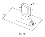
- FIG. 1A and FIG. 1B depict an imaging scanner 50 in accordance with some embodiments.
- the imaging scanner 50 has a window 56 and a housing 58 .
- the imaging scanner 50 is typically a portable reader that has a base for supporting itself on a flat surface 30 , such as, a countertop.
- the window 56 generally faces an operator at the workstation. As shown in FIG. 1A , the operator can slide or swipe the product 40 past the window 56 from right to left, or from left to right, in a “swipe” mode, to let an image of the barcode 40 on the product 42 be captured by the imaging scanner 50 . Alternatively, the operator can present the barcode 40 on the product 42 to the center of the window 56 in a “presentation” mode. The choice depends on operator preference or on the layout of the workstation.
- FIG. 2 is a schematic of an imaging scanner 50 in accordance with some embodiments.
- the imaging scanner 50 in FIG. 2 includes the following components: (1) an imaging sensor 62 positioned behind an imaging lens arrangement 60 ; (2) an illuminating lens arrangement 70 positioned in front of an illumination light source 72 ; (3) an aiming pattern generator 80 positioned in front of an aiming light source 82 ; and (4) a controller 90 .
- the imaging lens arrangement 60 , the illuminating lens arrangement 70 , and the aiming pattern generator 80 are positioned behind the window 56 .
- the imaging sensor 62 is mounted on a printed circuit board 91 in the imaging scanner.
- the imaging sensor 62 can be a CCD or a CMOS imaging device.
- the imaging sensor 62 generally includes multiple pixel elements. These multiple pixel elements can be formed by a one-dimensional array of photosensitive elements arranged linearly in a single row. These multiple pixel elements can also be formed by a two-dimensional array of photosensitive elements arranged in mutually orthogonal rows and columns.
- the imaging sensor 62 is operative to detect light captured by an imaging lens arrangement 60 along an optical path or axis 61 through the window 56 .
- the imaging sensor 62 and the imaging lens arrangement 60 are designed to operate together for capturing light scattered or reflected from a barcode 40 as imaging data over a two-dimensional imaging field of view (FOV).
- FOV two-dimensional imaging field of view
- the barcode 40 generally can be located anywhere in a working range of distances between a close-in working distance (WD 1 ) and a far-out working distance (WD 2 ). In one specific implementation, WD 1 is in a close proximity to the window 56 , and WD 2 is about a couple of feet from the window 56 .
- Some of the imaging scanners can include a range finding system for measuring the distance between the barcode 40 and the imaging lens arrangement 60 .
- Some of the imaging scanners can include an auto-focus system to enable a barcode be more clearly imaged with the imaging sensor 62 based on the measured distance of this barcode. In some implementations of the auto-focus system, the focus length of the imaging lens arrangement 60 is adjusted based on the measured distance of the barcode. In some other implementations of the auto-focus system, the distance between the imaging lens arrangement 60 and the imaging sensor 62 is adjusted based on the measured distance of the barcode.
- the illuminating lens arrangement 70 and the illumination light source 72 are designed to operate together for generating an illuminating light towards the barcode 40 during an illumination time period.
- the illumination light source 72 can include one or more light emitting diodes (LED).
- the illumination light source 72 can also include a laser or other kind of light sources.
- the aiming pattern generator 80 and the aiming light source 82 are designed to operate together for generating a visible aiming light pattern towards the barcode 40 . Such aiming pattern can be used by the operator to accurately aim the imaging scanner at the barcode.
- the aiming light source 82 can include one or more light emitting diodes (LED).
- the aiming light source 82 can also include a laser, LED, or other kind of light sources.
- the controller 90 such as a microprocessor, is operatively connected to the imaging sensor 62 , the illumination light source 72 , and the aiming light source 82 for controlling the operation of these components.
- the controller 90 can also be used to control other devices in the imaging scanner.
- the imaging scanner 50 includes a memory 94 that can be accessible by the controller 90 for storing and retrieving data.
- the controller 90 also includes a decoder for decoding one or more barcodes that are within the imaging field of view (FOV) of the imaging scanner 50 .
- the barcode 40 can be decoded by digitally processing a captured image of the barcode with a microprocessor.
- the controller 90 sends a command signal to energize the illumination light source 72 for a predetermined illumination time period.
- the controller 90 then exposes the imaging sensor 62 to capture an image of the barcode 40 .
- the captured image of the barcode 40 is transferred to the controller 90 as imaging data.
- imaging data is digitally processed by the decoder in the controller 90 to decode the barcode.
- the information obtained from decoding the barcode 40 is then stored in the memory 94 or sent to other devices for further processing.
- the illumination light source 72 usually is energized to address low ambient light conditions and to minimize hand jitter impact or swiping objects though the FOV on reading performance. On the other hand having bright illumination of an imaging scanner in constantly on state is annoying and bothersome for the user. It is also not efficient from power management perspective. Therefore it is beneficial to have an object sensing system which energizes illumination system when the object of interest is presented within the predetermined FOV of the imaging scanner 50 and at a certain distance from the scanner.
- FIGS. 3A-3B depict an imaging scanner 50 that includes an object detecting system behind the window 56 .
- the object detecting system in FIG. 3B includes an infrared LED 110 and a photodetector 120 .
- the infrared light projecting out of the window 56 mainly originates from one particular area—LED chip which may or may not have an auxiliary lens.
- LED chip which may or may not have an auxiliary lens.
- These implementations place some limitation on the effectiveness of the object detecting system. This limitation becomes apparent in case of reading barcodes from cell phones, a user application that has recently become very popular.
- cell phone screen is designed in such a way which minimizes reflected light from its surface. Therefore reflected/scattered light of the object sensor LED is very low, which is nearly impossible for detection at larger distances.
- an imaging scanner 50 can be an bi-optic imager that includes a horizontal window 56 H and a vertical window 56 V, and the bi-optic imager can include one object detecting system behind the horizontal window 56 H and another object detecting systems behind the vertical window 56 V.
- the process of capturing one or more images of the barcode 40 can be triggered by the object detecting system behind the windows 56 H or 56 V.
- the bi-optic imager 50 can also include a customer-side window 56 C, an object detecting system behind the customer-side window 56 C can be used to detect the presence of an object 42 in front of the customer-side window 56 C.
- an object detecting system behind the customer-side window 56 C can be used to detect the presence of an object 42 in front of the customer-side window 56 C.
- the product 42 in FIG. 4A has a glassy surface or when the object 42 in FIG. 4B is a cell phone
- the specular reflections from the glassy surface or from the flat screen of the cell phone can adversely affect the performance of the object detecting systems in the bi-optic imager. It is generally desirable to provide an improved object detecting system.
- FIGS. 5-7 depict an improved object detecting system in accordance with some embodiments.
- the object detecting system in FIGS. 5-7 includes an infrared LED 110 , a photodetector 120 , a reflector 130 , and a scattering surface 140 that is also partially transparent.
- the object detecting system in FIGS. 5-7 is used for detecting the presence of an object in front of a window 56 .
- Such object detecting system can also be used for detecting the presence of an object in front of the horizontal window 56 H, the vertical window 56 V, or the customer-side window 56 C of a bi-optic imager as shown in FIGS. 4A-4B . Also shown in FIGS.
- FIGS. 5-7 are some of the key components of the imaging scanner 50 , such as, the imaging sensor 62 , the imaging lens arrangement 60 , the illuminating lens arrangement 70 , and the illumination light source 72 .
- the field of view (FOV) of the imaging scanner 50 is also shown in FIGS. 5-7 .
- the object detecting system in FIGS. 5-7 is configured to make such wakeup sensor system less sensitive to specular surface orientation in the far field.
- the outgoing light for the wakeup sensor system are split into both directional and scattered light paths. This will increase the number of possible light path angles leaving the system which in turn will increase the probability that one of these light paths will reflect from the specular surface and reenter the wakeup system's field of view.
- the IR emitter has one component of its intensity that hits a mirror, providing highly directional outgoing path. This aids the system in illuminating far field objects.
- the scattering surface 140 is partially transparent, a portion of the invisible light from the infrared LED 110 passes through the scattering surface 140 and strikes the reflector 130 that is configured to reflect at least some of such invisible light towards the window 56 .
- some portion of the invisible light 210 from the infrared LED 110 passes through the scattering surface 140 , strikes the reflector 130 , and is reflected towards the window 56 as light 219 ; in addition, some portion of the invisible light 220 from the infrared LED 110 passes through the scattering surface 140 , strikes the reflector 130 , and is reflected towards the window 56 as light 229 .
- some portion of light rays from the infrared LED 110 propagating in a direction between the ray of light 210 and the ray of light 220 will be reflected out of the window 56 as light rays propagating in a direction between the ray of light 219 and the ray of light 229 .
- the IR emitter has another component of its intensity that hits a scattering surface, which provides outgoing light in many different directions. This aids the system in illuminating nearby specular surfaces at many different angles.
- some portion of the invisible light from the infrared LED 110 after scattered by the scattering surface 140 , propagates out of the window 56 directly or out of the window 56 indirectly after further scattered by other surfaces.
- some portion of the invisible light 210 from the infrared LED 110 after scattered by the scattering surface 140 , propagates out of the window 56 directly as light 212 .
- some portion of the invisible light 210 from the infrared LED 110 is scattered by the scattering surface 140 as light 211 ; subsequently, some of the light 211 , after further scattering by one or more surfaces, propagates out of the window 56 indirectly as light 213 , light 215 , or 216 . Similarly, some portion of the invisible light 220 from the infrared LED 110 , after scattered by the scattering surface 140 , propagates out of the window 56 directly as light 221 and light 222 .
- the wakeup system's field of view can be broken down into more than one component, each pointing in a generally different direction. This can increase the chance that it will see a highly directional returning light ray that has reflected from a specular surface.
- the field of view of the object detecting system includes at least two components—a first sub-field of view 300 and a second sub-field of view 400 —each pointing in a generally different direction.
- the first sub-field of view 300 falls upon the reflector 130 which angles the field of view to receive incoming rays that are generally parallel to the imaging path and downward angled incoming rays; furthermore, the front aperture 150 for the IR detector 120 is left open so that the photodetector 120 can see upward angled incoming rays in the second sub-field of view 400 .
- light ray 330 within the first sub-field of view 300 is reflected by the reflector 130 as light ray 331 that is detected by the photodetector 120 after passing through the front aperture 150 .
- Light ray 430 within the second sub-field of view 400 after passing through the front aperture 150 , is also detected by the photodetector 120 .
- the wakeup system can include additional apertures positioned in front of the infrared LED 110 or the photodetector 120 for defining the first sub-field of view 300 and the second sub-field of view 400 .
- the object detecting system as shown in FIGS. 5-7 can retain good performance on far field objects of a non-specular nature, and also have good performance on near field objects of a specular nature. This is ideal for a scanner that wants to detect reflective objects that are presented to it in the near field, such as a customer facing scanner that wants to wake up when a highly specular phone surface is presented to it.
- a includes . . . a”, “contains . . . a” does not, without more constraints, preclude the existence of additional identical elements in the process, method, article, or apparatus that comprises, has, includes, contains the element.
- the terms “a” and “an” are defined as one or more unless explicitly stated otherwise herein.
- the terms “substantially”, “essentially”, “approximately”, “about” or any other version thereof, are defined as being close to as understood by one of ordinary skill in the art, and in one non-limiting embodiment the term is defined to be within 10%, in another embodiment within 5%, in another embodiment within 1% and in another embodiment within 0.5%.
- the term “coupled” as used herein is defined as connected, although not necessarily directly and not necessarily mechanically.
- a device or structure that is “configured” in a certain way is configured in at least that way, but may also be configured in ways that are not listed.
- processors such as microprocessors, digital signal processors, customized processors and field programmable gate arrays (FPGAs) and unique stored program instructions (including both software and firmware) that control the one or more processors to implement, in conjunction with certain non-processor circuits, some, most, or all of the functions of the method and/or apparatus described herein.
- processors or “processing devices” such as microprocessors, digital signal processors, customized processors and field programmable gate arrays (FPGAs) and unique stored program instructions (including both software and firmware) that control the one or more processors to implement, in conjunction with certain non-processor circuits, some, most, or all of the functions of the method and/or apparatus described herein.
- FPGAs field programmable gate arrays
- unique stored program instructions including both software and firmware
- an embodiment can be implemented as a computer-readable storage medium having computer readable code stored thereon for programming a computer (e.g., comprising a processor) to perform a method as described and claimed herein.
- Examples of such computer-readable storage mediums include, but are not limited to, a hard disk, a CD-ROM, an optical storage device, a magnetic storage device, a ROM (Read Only Memory), a PROM (Programmable Read Only Memory), an EPROM (Erasable Programmable Read Only Memory), an EEPROM (Electrically Erasable Programmable Read Only Memory) and a Flash memory.
Abstract
Description
Claims (20)
Priority Applications (2)
| Application Number | Priority Date | Filing Date | Title |
|---|---|---|---|
| US13/646,830 US8847150B2 (en) | 2012-10-08 | 2012-10-08 | Object detecting system for imaging-based barcode readers |
| PCT/US2013/063021 WO2014058671A1 (en) | 2012-10-08 | 2013-10-02 | Object detecting system for imaging-based barcode readers |
Applications Claiming Priority (1)
| Application Number | Priority Date | Filing Date | Title |
|---|---|---|---|
| US13/646,830 US8847150B2 (en) | 2012-10-08 | 2012-10-08 | Object detecting system for imaging-based barcode readers |
Publications (2)
| Publication Number | Publication Date |
|---|---|
| US20140097337A1 US20140097337A1 (en) | 2014-04-10 |
| US8847150B2 true US8847150B2 (en) | 2014-09-30 |
Family
ID=49328684
Family Applications (1)
| Application Number | Title | Priority Date | Filing Date |
|---|---|---|---|
| US13/646,830 Active 2033-04-20 US8847150B2 (en) | 2012-10-08 | 2012-10-08 | Object detecting system for imaging-based barcode readers |
Country Status (2)
| Country | Link |
|---|---|
| US (1) | US8847150B2 (en) |
| WO (1) | WO2014058671A1 (en) |
Cited By (4)
| Publication number | Priority date | Publication date | Assignee | Title |
|---|---|---|---|---|
| WO2020046519A1 (en) * | 2018-08-28 | 2020-03-05 | Intuit Inc. | System and method for unique identifier detection based on invisible light |
| TWI709911B (en) * | 2019-02-01 | 2020-11-11 | 亞旭電腦股份有限公司 | Barcode reading apparatus |
| US11182572B2 (en) | 2019-12-20 | 2021-11-23 | Zebra Technologies Corporation | System and method of selective auxiliary data capture |
| US11295104B2 (en) | 2020-06-10 | 2022-04-05 | Zebra Technologies Corporation | Methods and apparatus to read barcodes on reflective surfaces |
Families Citing this family (5)
| Publication number | Priority date | Publication date | Assignee | Title |
|---|---|---|---|---|
| USD735197S1 (en) * | 2014-03-26 | 2015-07-28 | Optoelectronics Co., Ltd. | Optical information reader |
| US9911023B2 (en) * | 2015-08-17 | 2018-03-06 | Hand Held Products, Inc. | Indicia reader having a filtered multifunction image sensor |
| USD910021S1 (en) | 2019-01-11 | 2021-02-09 | Zebra Technologies Corporation | Data capture device |
| USD961593S1 (en) * | 2020-08-26 | 2022-08-23 | Hand Held Products, Inc. | Barcode scanner |
| US11687749B2 (en) | 2020-09-04 | 2023-06-27 | Datalogic Ip Tech S.R.L. | Code reader and related method for object detection based on image area percentage threshold |
Citations (24)
| Publication number | Priority date | Publication date | Assignee | Title |
|---|---|---|---|---|
| US4782219A (en) * | 1986-07-02 | 1988-11-01 | Laser Identification Systems, Inc. | System and method for reading specular barcodes |
| US5406060A (en) * | 1993-05-06 | 1995-04-11 | Opticon Inc. | Bar code reader for sensing at an acute angle |
| US5586212A (en) * | 1994-07-06 | 1996-12-17 | Hewlett-Packard | Optical wave guide for hand-held scanner |
| US5585616A (en) * | 1995-05-05 | 1996-12-17 | Rockwell International Corporation | Camera for capturing and decoding machine-readable matrix symbol images applied to reflective surfaces |
| US6039255A (en) * | 1996-08-28 | 2000-03-21 | Asahi Kogaku Kogyo Kabushiki Kaisha | Data symbol reading apparatus |
| US6557765B1 (en) | 1994-03-18 | 2003-05-06 | Fujitsu Limited | Data processing terminal |
| US6712270B2 (en) | 2002-08-15 | 2004-03-30 | Symbol Technologies, Inc. | Positioning of photodetectors in optical scanning modules for use in bar code readers for reducing specular reflection |
| US6854650B2 (en) * | 2002-04-10 | 2005-02-15 | Microscan Systems, Inc. | Mirrored surface optical symbol scanner |
| US6917723B1 (en) | 2000-04-25 | 2005-07-12 | Psc Scanning, Inc. | Optical data reader with control mechanism implemented behind the window |
| US7007844B2 (en) | 2003-10-02 | 2006-03-07 | Symbol Technologies, Inc. | Reader for electro-optically reading indicia through vertical window at which full coverage, omni-directional scan pattern is generated |
| US7017812B1 (en) | 2003-11-26 | 2006-03-28 | The United States Of America As Represented By The Administrator Of The National Aeronautics And Space Administration | Variable distance angular symbology reader |
| WO2006060785A2 (en) | 2004-12-01 | 2006-06-08 | Datalogic Scanning, Inc. | Triggering illumination for a data reader |
| US7398927B2 (en) | 2005-01-26 | 2008-07-15 | Datalogic Scanning, Inc. | Data reader and methods for imaging targets subject to specular reflection |
| US7516899B2 (en) * | 2006-03-06 | 2009-04-14 | V.L. Engineering, Inc. | Hand held wireless reading viewer of invisible bar codes |
| US7614563B1 (en) | 2005-12-29 | 2009-11-10 | Cognex Technology And Investment Corporation | System and method for providing diffuse illumination in a symbology reader |
| US7617984B2 (en) | 2004-12-16 | 2009-11-17 | Cognex Technology And Investment Corporation | Hand held symbology reader illumination diffuser |
| WO2010036277A1 (en) | 2008-09-24 | 2010-04-01 | Optoelectronics Co., Ltd. | Optical code detection with image exposure control |
| US7762464B2 (en) | 2007-06-28 | 2010-07-27 | Symbol Technologies, Inc. | Control of specular reflection in imaging reader |
| US7796489B2 (en) * | 2007-09-14 | 2010-09-14 | Sunplus Mmedia Inc. | Optical head with diffuser structure |
| EP1690162B1 (en) | 2003-11-13 | 2012-01-18 | Metrologic Instruments, Inc. | Hand-supportable imaging-based bar code symbol reader supporting narrow-area and wide-area modes of illumination and image capture |
| US8102580B2 (en) | 2006-01-30 | 2012-01-24 | Duncan Wayne O | Scanning illumination system and method |
| US8181885B2 (en) | 2007-09-21 | 2012-05-22 | Silverbrook Research Pty Ltd | Method of imaging a coding pattern having an orientation identified via a plurality of direction components |
| US8196834B2 (en) | 2010-07-12 | 2012-06-12 | Symbol Technologies, Inc. | Scan engine with integrated object sensor in electro-optical readers |
| WO2012099977A2 (en) | 2011-01-18 | 2012-07-26 | Datalogic ADC, Inc. | Systems and methods for illuminating a scan volume of an optical code reader |
-
2012
- 2012-10-08 US US13/646,830 patent/US8847150B2/en active Active
-
2013
- 2013-10-02 WO PCT/US2013/063021 patent/WO2014058671A1/en active Application Filing
Patent Citations (24)
| Publication number | Priority date | Publication date | Assignee | Title |
|---|---|---|---|---|
| US4782219A (en) * | 1986-07-02 | 1988-11-01 | Laser Identification Systems, Inc. | System and method for reading specular barcodes |
| US5406060A (en) * | 1993-05-06 | 1995-04-11 | Opticon Inc. | Bar code reader for sensing at an acute angle |
| US6557765B1 (en) | 1994-03-18 | 2003-05-06 | Fujitsu Limited | Data processing terminal |
| US5586212A (en) * | 1994-07-06 | 1996-12-17 | Hewlett-Packard | Optical wave guide for hand-held scanner |
| US5585616A (en) * | 1995-05-05 | 1996-12-17 | Rockwell International Corporation | Camera for capturing and decoding machine-readable matrix symbol images applied to reflective surfaces |
| US6039255A (en) * | 1996-08-28 | 2000-03-21 | Asahi Kogaku Kogyo Kabushiki Kaisha | Data symbol reading apparatus |
| US6917723B1 (en) | 2000-04-25 | 2005-07-12 | Psc Scanning, Inc. | Optical data reader with control mechanism implemented behind the window |
| US6854650B2 (en) * | 2002-04-10 | 2005-02-15 | Microscan Systems, Inc. | Mirrored surface optical symbol scanner |
| US6712270B2 (en) | 2002-08-15 | 2004-03-30 | Symbol Technologies, Inc. | Positioning of photodetectors in optical scanning modules for use in bar code readers for reducing specular reflection |
| US7007844B2 (en) | 2003-10-02 | 2006-03-07 | Symbol Technologies, Inc. | Reader for electro-optically reading indicia through vertical window at which full coverage, omni-directional scan pattern is generated |
| EP1690162B1 (en) | 2003-11-13 | 2012-01-18 | Metrologic Instruments, Inc. | Hand-supportable imaging-based bar code symbol reader supporting narrow-area and wide-area modes of illumination and image capture |
| US7017812B1 (en) | 2003-11-26 | 2006-03-28 | The United States Of America As Represented By The Administrator Of The National Aeronautics And Space Administration | Variable distance angular symbology reader |
| WO2006060785A2 (en) | 2004-12-01 | 2006-06-08 | Datalogic Scanning, Inc. | Triggering illumination for a data reader |
| US7617984B2 (en) | 2004-12-16 | 2009-11-17 | Cognex Technology And Investment Corporation | Hand held symbology reader illumination diffuser |
| US7398927B2 (en) | 2005-01-26 | 2008-07-15 | Datalogic Scanning, Inc. | Data reader and methods for imaging targets subject to specular reflection |
| US7614563B1 (en) | 2005-12-29 | 2009-11-10 | Cognex Technology And Investment Corporation | System and method for providing diffuse illumination in a symbology reader |
| US8102580B2 (en) | 2006-01-30 | 2012-01-24 | Duncan Wayne O | Scanning illumination system and method |
| US7516899B2 (en) * | 2006-03-06 | 2009-04-14 | V.L. Engineering, Inc. | Hand held wireless reading viewer of invisible bar codes |
| US7762464B2 (en) | 2007-06-28 | 2010-07-27 | Symbol Technologies, Inc. | Control of specular reflection in imaging reader |
| US7796489B2 (en) * | 2007-09-14 | 2010-09-14 | Sunplus Mmedia Inc. | Optical head with diffuser structure |
| US8181885B2 (en) | 2007-09-21 | 2012-05-22 | Silverbrook Research Pty Ltd | Method of imaging a coding pattern having an orientation identified via a plurality of direction components |
| WO2010036277A1 (en) | 2008-09-24 | 2010-04-01 | Optoelectronics Co., Ltd. | Optical code detection with image exposure control |
| US8196834B2 (en) | 2010-07-12 | 2012-06-12 | Symbol Technologies, Inc. | Scan engine with integrated object sensor in electro-optical readers |
| WO2012099977A2 (en) | 2011-01-18 | 2012-07-26 | Datalogic ADC, Inc. | Systems and methods for illuminating a scan volume of an optical code reader |
Non-Patent Citations (1)
| Title |
|---|
| International Search Report and Written Opinion for counterpart International Patent Application No. PCT/US2013/063021 mailed Dec. 11, 2013. |
Cited By (4)
| Publication number | Priority date | Publication date | Assignee | Title |
|---|---|---|---|---|
| WO2020046519A1 (en) * | 2018-08-28 | 2020-03-05 | Intuit Inc. | System and method for unique identifier detection based on invisible light |
| TWI709911B (en) * | 2019-02-01 | 2020-11-11 | 亞旭電腦股份有限公司 | Barcode reading apparatus |
| US11182572B2 (en) | 2019-12-20 | 2021-11-23 | Zebra Technologies Corporation | System and method of selective auxiliary data capture |
| US11295104B2 (en) | 2020-06-10 | 2022-04-05 | Zebra Technologies Corporation | Methods and apparatus to read barcodes on reflective surfaces |
Also Published As
| Publication number | Publication date |
|---|---|
| US20140097337A1 (en) | 2014-04-10 |
| WO2014058671A1 (en) | 2014-04-17 |
Similar Documents
| Publication | Publication Date | Title |
|---|---|---|
| US8847150B2 (en) | Object detecting system for imaging-based barcode readers | |
| US8389945B1 (en) | Object detecting system in imaging-based barcode readers | |
| EP2414989B1 (en) | Exposure control for multi-imaging scanner | |
| US9202094B1 (en) | Aiming pattern shape as distance sensor for barcode scanner | |
| US8857719B2 (en) | Decoding barcodes displayed on cell phone | |
| US9111163B2 (en) | Apparatus for and method of electro-optically reading a selected target by image capture from a picklist of targets | |
| US20130334314A1 (en) | Aiming system for imaging scanner | |
| AU2015298237B2 (en) | Detectiing window deterioration on barcode scanning workstation | |
| WO2015009557A1 (en) | Compact aiming light assembly and imaging module for, and method of, generating an aiming light spot with increased brightness and uniformity from a light emitting diode over an extended working distance range in an imaging reader | |
| US8960551B2 (en) | Method of decoding barcode with imaging scanner having multiple object sensors | |
| US8757494B2 (en) | Illumination system in imaging scanner | |
| US8479993B2 (en) | Method for aiming imaging scanner with single trigger | |
| US8752767B2 (en) | Illumination system with prism for use in imaging scanner | |
| US8534559B2 (en) | Imaging slot scanner with multiple field of view | |
| US8590793B2 (en) | Imaging-based barcode readers having curved window | |
| US10491790B2 (en) | Imaging module and reader for, and method of, variably illuminating targets to be read by image capture over a range of working distances | |
| US9507985B2 (en) | Optical lens for using in illumination system of imaging scanner | |
| US8657195B2 (en) | Document capture with imaging-based bar code readers | |
| US8342410B2 (en) | Method and apparatus for increasing brightness of aiming pattern in imaging scanner | |
| CN106462723B (en) | Decoding barcodes using intelligent linear selection lists | |
| US9483669B2 (en) | Barcode imaging workstation having sequentially activated object sensors | |
| US9004363B2 (en) | Diffuser engine for barcode imaging scanner | |
| US10318778B2 (en) | Reducing perceived brightness of illumination light source in electro-optical readers that illuminate and read targets by image capture | |
| US8511559B2 (en) | Apparatus for and method of reading targets by image captured by processing captured target images in a batch or free-running mode of operation |
Legal Events
| Date | Code | Title | Description |
|---|---|---|---|
| AS | Assignment |
Owner name: SYMBOL TECHNOLOGIES, INC., NEW YORK Free format text: ASSIGNMENT OF ASSIGNORS INTEREST;ASSIGNORS:HANDSHAW, DARRAN M.;DRZYMALA, MARK E.;GIORDANO, JOSEPH D.;REEL/FRAME:029089/0521 Effective date: 20121005 |
|
| STCF | Information on status: patent grant |
Free format text: PATENTED CASE |
|
| AS | Assignment |
Owner name: MORGAN STANLEY SENIOR FUNDING, INC. AS THE COLLATERAL AGENT, MARYLAND Free format text: SECURITY AGREEMENT;ASSIGNORS:ZIH CORP.;LASER BAND, LLC;ZEBRA ENTERPRISE SOLUTIONS CORP.;AND OTHERS;REEL/FRAME:034114/0270 Effective date: 20141027 Owner name: MORGAN STANLEY SENIOR FUNDING, INC. AS THE COLLATE Free format text: SECURITY AGREEMENT;ASSIGNORS:ZIH CORP.;LASER BAND, LLC;ZEBRA ENTERPRISE SOLUTIONS CORP.;AND OTHERS;REEL/FRAME:034114/0270 Effective date: 20141027 |
|
| AS | Assignment |
Owner name: SYMBOL TECHNOLOGIES, LLC, NEW YORK Free format text: CHANGE OF NAME;ASSIGNOR:SYMBOL TECHNOLOGIES, INC.;REEL/FRAME:036083/0640 Effective date: 20150410 |
|
| AS | Assignment |
Owner name: SYMBOL TECHNOLOGIES, INC., NEW YORK Free format text: RELEASE BY SECURED PARTY;ASSIGNOR:MORGAN STANLEY SENIOR FUNDING, INC.;REEL/FRAME:036371/0738 Effective date: 20150721 |
|
| MAFP | Maintenance fee payment |
Free format text: PAYMENT OF MAINTENANCE FEE, 4TH YEAR, LARGE ENTITY (ORIGINAL EVENT CODE: M1551) Year of fee payment: 4 |
|
| MAFP | Maintenance fee payment |
Free format text: PAYMENT OF MAINTENANCE FEE, 8TH YEAR, LARGE ENTITY (ORIGINAL EVENT CODE: M1552); ENTITY STATUS OF PATENT OWNER: LARGE ENTITY Year of fee payment: 8 |