US8834572B2 - Arthrodesis implant - Google Patents
Arthrodesis implant Download PDFInfo
- Publication number
- US8834572B2 US8834572B2 US13/583,685 US201113583685A US8834572B2 US 8834572 B2 US8834572 B2 US 8834572B2 US 201113583685 A US201113583685 A US 201113583685A US 8834572 B2 US8834572 B2 US 8834572B2
- Authority
- US
- United States
- Prior art keywords
- implant
- central core
- bone
- longitudinal axis
- section
- Prior art date
- Legal status (The legal status is an assumption and is not a legal conclusion. Google has not performed a legal analysis and makes no representation as to the accuracy of the status listed.)
- Active, expires
Links
Images


Classifications
-
- A—HUMAN NECESSITIES
- A61—MEDICAL OR VETERINARY SCIENCE; HYGIENE
- A61F—FILTERS IMPLANTABLE INTO BLOOD VESSELS; PROSTHESES; DEVICES PROVIDING PATENCY TO, OR PREVENTING COLLAPSING OF, TUBULAR STRUCTURES OF THE BODY, e.g. STENTS; ORTHOPAEDIC, NURSING OR CONTRACEPTIVE DEVICES; FOMENTATION; TREATMENT OR PROTECTION OF EYES OR EARS; BANDAGES, DRESSINGS OR ABSORBENT PADS; FIRST-AID KITS
- A61F2/00—Filters implantable into blood vessels; Prostheses, i.e. artificial substitutes or replacements for parts of the body; Appliances for connecting them with the body; Devices providing patency to, or preventing collapsing of, tubular structures of the body, e.g. stents
- A61F2/02—Prostheses implantable into the body
- A61F2/30—Joints
- A61F2/42—Joints for wrists or ankles; for hands, e.g. fingers; for feet, e.g. toes
-
- A—HUMAN NECESSITIES
- A61—MEDICAL OR VETERINARY SCIENCE; HYGIENE
- A61B—DIAGNOSIS; SURGERY; IDENTIFICATION
- A61B17/00—Surgical instruments, devices or methods, e.g. tourniquets
- A61B17/56—Surgical instruments or methods for treatment of bones or joints; Devices specially adapted therefor
- A61B17/58—Surgical instruments or methods for treatment of bones or joints; Devices specially adapted therefor for osteosynthesis, e.g. bone plates, screws, setting implements or the like
- A61B17/68—Internal fixation devices, including fasteners and spinal fixators, even if a part thereof projects from the skin
- A61B17/72—Intramedullary pins, nails or other devices
- A61B17/7233—Intramedullary pins, nails or other devices with special means of locking the nail to the bone
- A61B17/7258—Intramedullary pins, nails or other devices with special means of locking the nail to the bone with laterally expanding parts, e.g. for gripping the bone
- A61B17/7266—Intramedullary pins, nails or other devices with special means of locking the nail to the bone with laterally expanding parts, e.g. for gripping the bone with fingers moving radially outwardly
-
- A—HUMAN NECESSITIES
- A61—MEDICAL OR VETERINARY SCIENCE; HYGIENE
- A61B—DIAGNOSIS; SURGERY; IDENTIFICATION
- A61B17/00—Surgical instruments, devices or methods, e.g. tourniquets
- A61B17/56—Surgical instruments or methods for treatment of bones or joints; Devices specially adapted therefor
- A61B17/58—Surgical instruments or methods for treatment of bones or joints; Devices specially adapted therefor for osteosynthesis, e.g. bone plates, screws, setting implements or the like
- A61B17/68—Internal fixation devices, including fasteners and spinal fixators, even if a part thereof projects from the skin
- A61B17/72—Intramedullary pins, nails or other devices
- A61B17/7283—Intramedullary pins, nails or other devices with special cross-section of the nail
-
- A—HUMAN NECESSITIES
- A61—MEDICAL OR VETERINARY SCIENCE; HYGIENE
- A61B—DIAGNOSIS; SURGERY; IDENTIFICATION
- A61B17/00—Surgical instruments, devices or methods, e.g. tourniquets
- A61B17/56—Surgical instruments or methods for treatment of bones or joints; Devices specially adapted therefor
- A61B17/58—Surgical instruments or methods for treatment of bones or joints; Devices specially adapted therefor for osteosynthesis, e.g. bone plates, screws, setting implements or the like
- A61B17/68—Internal fixation devices, including fasteners and spinal fixators, even if a part thereof projects from the skin
- A61B17/72—Intramedullary pins, nails or other devices
- A61B17/7291—Intramedullary pins, nails or other devices for small bones, e.g. in the foot, ankle, hand or wrist
-
- A—HUMAN NECESSITIES
- A61—MEDICAL OR VETERINARY SCIENCE; HYGIENE
- A61F—FILTERS IMPLANTABLE INTO BLOOD VESSELS; PROSTHESES; DEVICES PROVIDING PATENCY TO, OR PREVENTING COLLAPSING OF, TUBULAR STRUCTURES OF THE BODY, e.g. STENTS; ORTHOPAEDIC, NURSING OR CONTRACEPTIVE DEVICES; FOMENTATION; TREATMENT OR PROTECTION OF EYES OR EARS; BANDAGES, DRESSINGS OR ABSORBENT PADS; FIRST-AID KITS
- A61F2/00—Filters implantable into blood vessels; Prostheses, i.e. artificial substitutes or replacements for parts of the body; Appliances for connecting them with the body; Devices providing patency to, or preventing collapsing of, tubular structures of the body, e.g. stents
- A61F2/02—Prostheses implantable into the body
- A61F2/30—Joints
- A61F2/42—Joints for wrists or ankles; for hands, e.g. fingers; for feet, e.g. toes
- A61F2/4225—Joints for wrists or ankles; for hands, e.g. fingers; for feet, e.g. toes for feet, e.g. toes
-
- A—HUMAN NECESSITIES
- A61—MEDICAL OR VETERINARY SCIENCE; HYGIENE
- A61F—FILTERS IMPLANTABLE INTO BLOOD VESSELS; PROSTHESES; DEVICES PROVIDING PATENCY TO, OR PREVENTING COLLAPSING OF, TUBULAR STRUCTURES OF THE BODY, e.g. STENTS; ORTHOPAEDIC, NURSING OR CONTRACEPTIVE DEVICES; FOMENTATION; TREATMENT OR PROTECTION OF EYES OR EARS; BANDAGES, DRESSINGS OR ABSORBENT PADS; FIRST-AID KITS
- A61F2/00—Filters implantable into blood vessels; Prostheses, i.e. artificial substitutes or replacements for parts of the body; Appliances for connecting them with the body; Devices providing patency to, or preventing collapsing of, tubular structures of the body, e.g. stents
- A61F2/02—Prostheses implantable into the body
- A61F2/30—Joints
- A61F2/42—Joints for wrists or ankles; for hands, e.g. fingers; for feet, e.g. toes
- A61F2/4241—Joints for wrists or ankles; for hands, e.g. fingers; for feet, e.g. toes for hands, e.g. fingers
-
- A—HUMAN NECESSITIES
- A61—MEDICAL OR VETERINARY SCIENCE; HYGIENE
- A61B—DIAGNOSIS; SURGERY; IDENTIFICATION
- A61B17/00—Surgical instruments, devices or methods, e.g. tourniquets
- A61B17/56—Surgical instruments or methods for treatment of bones or joints; Devices specially adapted therefor
- A61B17/58—Surgical instruments or methods for treatment of bones or joints; Devices specially adapted therefor for osteosynthesis, e.g. bone plates, screws, setting implements or the like
- A61B17/68—Internal fixation devices, including fasteners and spinal fixators, even if a part thereof projects from the skin
- A61B17/72—Intramedullary pins, nails or other devices
- A61B17/7216—Intramedullary pins, nails or other devices for bone lengthening or compression
- A61B17/7225—Intramedullary pins, nails or other devices for bone lengthening or compression for bone compression
-
- A—HUMAN NECESSITIES
- A61—MEDICAL OR VETERINARY SCIENCE; HYGIENE
- A61F—FILTERS IMPLANTABLE INTO BLOOD VESSELS; PROSTHESES; DEVICES PROVIDING PATENCY TO, OR PREVENTING COLLAPSING OF, TUBULAR STRUCTURES OF THE BODY, e.g. STENTS; ORTHOPAEDIC, NURSING OR CONTRACEPTIVE DEVICES; FOMENTATION; TREATMENT OR PROTECTION OF EYES OR EARS; BANDAGES, DRESSINGS OR ABSORBENT PADS; FIRST-AID KITS
- A61F2/00—Filters implantable into blood vessels; Prostheses, i.e. artificial substitutes or replacements for parts of the body; Appliances for connecting them with the body; Devices providing patency to, or preventing collapsing of, tubular structures of the body, e.g. stents
- A61F2/02—Prostheses implantable into the body
- A61F2/30—Joints
- A61F2002/30001—Additional features of subject-matter classified in A61F2/28, A61F2/30 and subgroups thereof
- A61F2002/30003—Material related properties of the prosthesis or of a coating on the prosthesis
- A61F2002/3006—Properties of materials and coating materials
- A61F2002/30062—(bio)absorbable, biodegradable, bioerodable, (bio)resorbable, resorptive
-
- A—HUMAN NECESSITIES
- A61—MEDICAL OR VETERINARY SCIENCE; HYGIENE
- A61F—FILTERS IMPLANTABLE INTO BLOOD VESSELS; PROSTHESES; DEVICES PROVIDING PATENCY TO, OR PREVENTING COLLAPSING OF, TUBULAR STRUCTURES OF THE BODY, e.g. STENTS; ORTHOPAEDIC, NURSING OR CONTRACEPTIVE DEVICES; FOMENTATION; TREATMENT OR PROTECTION OF EYES OR EARS; BANDAGES, DRESSINGS OR ABSORBENT PADS; FIRST-AID KITS
- A61F2/00—Filters implantable into blood vessels; Prostheses, i.e. artificial substitutes or replacements for parts of the body; Appliances for connecting them with the body; Devices providing patency to, or preventing collapsing of, tubular structures of the body, e.g. stents
- A61F2/02—Prostheses implantable into the body
- A61F2/30—Joints
- A61F2002/30001—Additional features of subject-matter classified in A61F2/28, A61F2/30 and subgroups thereof
- A61F2002/30108—Shapes
- A61F2002/3011—Cross-sections or two-dimensional shapes
- A61F2002/30112—Rounded shapes, e.g. with rounded corners
-
- A—HUMAN NECESSITIES
- A61—MEDICAL OR VETERINARY SCIENCE; HYGIENE
- A61F—FILTERS IMPLANTABLE INTO BLOOD VESSELS; PROSTHESES; DEVICES PROVIDING PATENCY TO, OR PREVENTING COLLAPSING OF, TUBULAR STRUCTURES OF THE BODY, e.g. STENTS; ORTHOPAEDIC, NURSING OR CONTRACEPTIVE DEVICES; FOMENTATION; TREATMENT OR PROTECTION OF EYES OR EARS; BANDAGES, DRESSINGS OR ABSORBENT PADS; FIRST-AID KITS
- A61F2/00—Filters implantable into blood vessels; Prostheses, i.e. artificial substitutes or replacements for parts of the body; Appliances for connecting them with the body; Devices providing patency to, or preventing collapsing of, tubular structures of the body, e.g. stents
- A61F2/02—Prostheses implantable into the body
- A61F2/30—Joints
- A61F2002/30001—Additional features of subject-matter classified in A61F2/28, A61F2/30 and subgroups thereof
- A61F2002/30108—Shapes
- A61F2002/3011—Cross-sections or two-dimensional shapes
- A61F2002/30159—Concave polygonal shapes
- A61F2002/30171—Concave polygonal shapes rosette- or star-shaped
-
- A—HUMAN NECESSITIES
- A61—MEDICAL OR VETERINARY SCIENCE; HYGIENE
- A61F—FILTERS IMPLANTABLE INTO BLOOD VESSELS; PROSTHESES; DEVICES PROVIDING PATENCY TO, OR PREVENTING COLLAPSING OF, TUBULAR STRUCTURES OF THE BODY, e.g. STENTS; ORTHOPAEDIC, NURSING OR CONTRACEPTIVE DEVICES; FOMENTATION; TREATMENT OR PROTECTION OF EYES OR EARS; BANDAGES, DRESSINGS OR ABSORBENT PADS; FIRST-AID KITS
- A61F2/00—Filters implantable into blood vessels; Prostheses, i.e. artificial substitutes or replacements for parts of the body; Appliances for connecting them with the body; Devices providing patency to, or preventing collapsing of, tubular structures of the body, e.g. stents
- A61F2/02—Prostheses implantable into the body
- A61F2/30—Joints
- A61F2002/30001—Additional features of subject-matter classified in A61F2/28, A61F2/30 and subgroups thereof
- A61F2002/30108—Shapes
- A61F2002/3011—Cross-sections or two-dimensional shapes
- A61F2002/30159—Concave polygonal shapes
- A61F2002/30172—T-shaped
-
- A—HUMAN NECESSITIES
- A61—MEDICAL OR VETERINARY SCIENCE; HYGIENE
- A61F—FILTERS IMPLANTABLE INTO BLOOD VESSELS; PROSTHESES; DEVICES PROVIDING PATENCY TO, OR PREVENTING COLLAPSING OF, TUBULAR STRUCTURES OF THE BODY, e.g. STENTS; ORTHOPAEDIC, NURSING OR CONTRACEPTIVE DEVICES; FOMENTATION; TREATMENT OR PROTECTION OF EYES OR EARS; BANDAGES, DRESSINGS OR ABSORBENT PADS; FIRST-AID KITS
- A61F2/00—Filters implantable into blood vessels; Prostheses, i.e. artificial substitutes or replacements for parts of the body; Appliances for connecting them with the body; Devices providing patency to, or preventing collapsing of, tubular structures of the body, e.g. stents
- A61F2/02—Prostheses implantable into the body
- A61F2/30—Joints
- A61F2002/30001—Additional features of subject-matter classified in A61F2/28, A61F2/30 and subgroups thereof
- A61F2002/30108—Shapes
- A61F2002/3011—Cross-sections or two-dimensional shapes
- A61F2002/30159—Concave polygonal shapes
- A61F2002/30181—Y-shaped
-
- A—HUMAN NECESSITIES
- A61—MEDICAL OR VETERINARY SCIENCE; HYGIENE
- A61F—FILTERS IMPLANTABLE INTO BLOOD VESSELS; PROSTHESES; DEVICES PROVIDING PATENCY TO, OR PREVENTING COLLAPSING OF, TUBULAR STRUCTURES OF THE BODY, e.g. STENTS; ORTHOPAEDIC, NURSING OR CONTRACEPTIVE DEVICES; FOMENTATION; TREATMENT OR PROTECTION OF EYES OR EARS; BANDAGES, DRESSINGS OR ABSORBENT PADS; FIRST-AID KITS
- A61F2/00—Filters implantable into blood vessels; Prostheses, i.e. artificial substitutes or replacements for parts of the body; Appliances for connecting them with the body; Devices providing patency to, or preventing collapsing of, tubular structures of the body, e.g. stents
- A61F2/02—Prostheses implantable into the body
- A61F2/30—Joints
- A61F2002/30001—Additional features of subject-matter classified in A61F2/28, A61F2/30 and subgroups thereof
- A61F2002/30316—The prosthesis having different structural features at different locations within the same prosthesis; Connections between prosthetic parts; Special structural features of bone or joint prostheses not otherwise provided for
- A61F2002/30535—Special structural features of bone or joint prostheses not otherwise provided for
- A61F2002/30565—Special structural features of bone or joint prostheses not otherwise provided for having spring elements
- A61F2002/30571—Leaf springs
-
- A—HUMAN NECESSITIES
- A61—MEDICAL OR VETERINARY SCIENCE; HYGIENE
- A61F—FILTERS IMPLANTABLE INTO BLOOD VESSELS; PROSTHESES; DEVICES PROVIDING PATENCY TO, OR PREVENTING COLLAPSING OF, TUBULAR STRUCTURES OF THE BODY, e.g. STENTS; ORTHOPAEDIC, NURSING OR CONTRACEPTIVE DEVICES; FOMENTATION; TREATMENT OR PROTECTION OF EYES OR EARS; BANDAGES, DRESSINGS OR ABSORBENT PADS; FIRST-AID KITS
- A61F2/00—Filters implantable into blood vessels; Prostheses, i.e. artificial substitutes or replacements for parts of the body; Appliances for connecting them with the body; Devices providing patency to, or preventing collapsing of, tubular structures of the body, e.g. stents
- A61F2/02—Prostheses implantable into the body
- A61F2/30—Joints
- A61F2002/30001—Additional features of subject-matter classified in A61F2/28, A61F2/30 and subgroups thereof
- A61F2002/30316—The prosthesis having different structural features at different locations within the same prosthesis; Connections between prosthetic parts; Special structural features of bone or joint prostheses not otherwise provided for
- A61F2002/30535—Special structural features of bone or joint prostheses not otherwise provided for
- A61F2002/30594—Special structural features of bone or joint prostheses not otherwise provided for slotted, e.g. radial or meridian slot ending in a polar aperture, non-polar slots, horizontal or arcuate slots
-
- A—HUMAN NECESSITIES
- A61—MEDICAL OR VETERINARY SCIENCE; HYGIENE
- A61F—FILTERS IMPLANTABLE INTO BLOOD VESSELS; PROSTHESES; DEVICES PROVIDING PATENCY TO, OR PREVENTING COLLAPSING OF, TUBULAR STRUCTURES OF THE BODY, e.g. STENTS; ORTHOPAEDIC, NURSING OR CONTRACEPTIVE DEVICES; FOMENTATION; TREATMENT OR PROTECTION OF EYES OR EARS; BANDAGES, DRESSINGS OR ABSORBENT PADS; FIRST-AID KITS
- A61F2/00—Filters implantable into blood vessels; Prostheses, i.e. artificial substitutes or replacements for parts of the body; Appliances for connecting them with the body; Devices providing patency to, or preventing collapsing of, tubular structures of the body, e.g. stents
- A61F2/02—Prostheses implantable into the body
- A61F2/30—Joints
- A61F2002/30001—Additional features of subject-matter classified in A61F2/28, A61F2/30 and subgroups thereof
- A61F2002/30621—Features concerning the anatomical functioning or articulation of the prosthetic joint
- A61F2002/30622—Implant for fusing a joint or bone material
-
- A—HUMAN NECESSITIES
- A61—MEDICAL OR VETERINARY SCIENCE; HYGIENE
- A61F—FILTERS IMPLANTABLE INTO BLOOD VESSELS; PROSTHESES; DEVICES PROVIDING PATENCY TO, OR PREVENTING COLLAPSING OF, TUBULAR STRUCTURES OF THE BODY, e.g. STENTS; ORTHOPAEDIC, NURSING OR CONTRACEPTIVE DEVICES; FOMENTATION; TREATMENT OR PROTECTION OF EYES OR EARS; BANDAGES, DRESSINGS OR ABSORBENT PADS; FIRST-AID KITS
- A61F2/00—Filters implantable into blood vessels; Prostheses, i.e. artificial substitutes or replacements for parts of the body; Appliances for connecting them with the body; Devices providing patency to, or preventing collapsing of, tubular structures of the body, e.g. stents
- A61F2/02—Prostheses implantable into the body
- A61F2/30—Joints
- A61F2/30767—Special external or bone-contacting surface, e.g. coating for improving bone ingrowth
- A61F2/30771—Special external or bone-contacting surface, e.g. coating for improving bone ingrowth applied in original prostheses, e.g. holes or grooves
- A61F2002/30904—Special external or bone-contacting surface, e.g. coating for improving bone ingrowth applied in original prostheses, e.g. holes or grooves serrated profile, i.e. saw-toothed
-
- A—HUMAN NECESSITIES
- A61—MEDICAL OR VETERINARY SCIENCE; HYGIENE
- A61F—FILTERS IMPLANTABLE INTO BLOOD VESSELS; PROSTHESES; DEVICES PROVIDING PATENCY TO, OR PREVENTING COLLAPSING OF, TUBULAR STRUCTURES OF THE BODY, e.g. STENTS; ORTHOPAEDIC, NURSING OR CONTRACEPTIVE DEVICES; FOMENTATION; TREATMENT OR PROTECTION OF EYES OR EARS; BANDAGES, DRESSINGS OR ABSORBENT PADS; FIRST-AID KITS
- A61F2/00—Filters implantable into blood vessels; Prostheses, i.e. artificial substitutes or replacements for parts of the body; Appliances for connecting them with the body; Devices providing patency to, or preventing collapsing of, tubular structures of the body, e.g. stents
- A61F2/02—Prostheses implantable into the body
- A61F2/30—Joints
- A61F2/42—Joints for wrists or ankles; for hands, e.g. fingers; for feet, e.g. toes
- A61F2/4225—Joints for wrists or ankles; for hands, e.g. fingers; for feet, e.g. toes for feet, e.g. toes
- A61F2002/4228—Joints for wrists or ankles; for hands, e.g. fingers; for feet, e.g. toes for feet, e.g. toes for interphalangeal joints, i.e. IP joints
-
- A61F2002/423—
-
- A—HUMAN NECESSITIES
- A61—MEDICAL OR VETERINARY SCIENCE; HYGIENE
- A61F—FILTERS IMPLANTABLE INTO BLOOD VESSELS; PROSTHESES; DEVICES PROVIDING PATENCY TO, OR PREVENTING COLLAPSING OF, TUBULAR STRUCTURES OF THE BODY, e.g. STENTS; ORTHOPAEDIC, NURSING OR CONTRACEPTIVE DEVICES; FOMENTATION; TREATMENT OR PROTECTION OF EYES OR EARS; BANDAGES, DRESSINGS OR ABSORBENT PADS; FIRST-AID KITS
- A61F2/00—Filters implantable into blood vessels; Prostheses, i.e. artificial substitutes or replacements for parts of the body; Appliances for connecting them with the body; Devices providing patency to, or preventing collapsing of, tubular structures of the body, e.g. stents
- A61F2/02—Prostheses implantable into the body
- A61F2/30—Joints
- A61F2/42—Joints for wrists or ankles; for hands, e.g. fingers; for feet, e.g. toes
- A61F2/4241—Joints for wrists or ankles; for hands, e.g. fingers; for feet, e.g. toes for hands, e.g. fingers
- A61F2002/4243—Joints for wrists or ankles; for hands, e.g. fingers; for feet, e.g. toes for hands, e.g. fingers for interphalangeal joints, i.e. IP joints
-
- A—HUMAN NECESSITIES
- A61—MEDICAL OR VETERINARY SCIENCE; HYGIENE
- A61F—FILTERS IMPLANTABLE INTO BLOOD VESSELS; PROSTHESES; DEVICES PROVIDING PATENCY TO, OR PREVENTING COLLAPSING OF, TUBULAR STRUCTURES OF THE BODY, e.g. STENTS; ORTHOPAEDIC, NURSING OR CONTRACEPTIVE DEVICES; FOMENTATION; TREATMENT OR PROTECTION OF EYES OR EARS; BANDAGES, DRESSINGS OR ABSORBENT PADS; FIRST-AID KITS
- A61F2210/00—Particular material properties of prostheses classified in groups A61F2/00 - A61F2/26 or A61F2/82 or A61F9/00 or A61F11/00 or subgroups thereof
- A61F2210/0004—Particular material properties of prostheses classified in groups A61F2/00 - A61F2/26 or A61F2/82 or A61F9/00 or A61F11/00 or subgroups thereof bioabsorbable
-
- A—HUMAN NECESSITIES
- A61—MEDICAL OR VETERINARY SCIENCE; HYGIENE
- A61F—FILTERS IMPLANTABLE INTO BLOOD VESSELS; PROSTHESES; DEVICES PROVIDING PATENCY TO, OR PREVENTING COLLAPSING OF, TUBULAR STRUCTURES OF THE BODY, e.g. STENTS; ORTHOPAEDIC, NURSING OR CONTRACEPTIVE DEVICES; FOMENTATION; TREATMENT OR PROTECTION OF EYES OR EARS; BANDAGES, DRESSINGS OR ABSORBENT PADS; FIRST-AID KITS
- A61F2230/00—Geometry of prostheses classified in groups A61F2/00 - A61F2/26 or A61F2/82 or A61F9/00 or A61F11/00 or subgroups thereof
- A61F2230/0002—Two-dimensional shapes, e.g. cross-sections
- A61F2230/0004—Rounded shapes, e.g. with rounded corners
-
- A—HUMAN NECESSITIES
- A61—MEDICAL OR VETERINARY SCIENCE; HYGIENE
- A61F—FILTERS IMPLANTABLE INTO BLOOD VESSELS; PROSTHESES; DEVICES PROVIDING PATENCY TO, OR PREVENTING COLLAPSING OF, TUBULAR STRUCTURES OF THE BODY, e.g. STENTS; ORTHOPAEDIC, NURSING OR CONTRACEPTIVE DEVICES; FOMENTATION; TREATMENT OR PROTECTION OF EYES OR EARS; BANDAGES, DRESSINGS OR ABSORBENT PADS; FIRST-AID KITS
- A61F2230/00—Geometry of prostheses classified in groups A61F2/00 - A61F2/26 or A61F2/82 or A61F9/00 or A61F11/00 or subgroups thereof
- A61F2230/0002—Two-dimensional shapes, e.g. cross-sections
- A61F2230/0028—Shapes in the form of latin or greek characters
- A61F2230/005—Rosette-shaped, e.g. star-shaped
-
- A—HUMAN NECESSITIES
- A61—MEDICAL OR VETERINARY SCIENCE; HYGIENE
- A61F—FILTERS IMPLANTABLE INTO BLOOD VESSELS; PROSTHESES; DEVICES PROVIDING PATENCY TO, OR PREVENTING COLLAPSING OF, TUBULAR STRUCTURES OF THE BODY, e.g. STENTS; ORTHOPAEDIC, NURSING OR CONTRACEPTIVE DEVICES; FOMENTATION; TREATMENT OR PROTECTION OF EYES OR EARS; BANDAGES, DRESSINGS OR ABSORBENT PADS; FIRST-AID KITS
- A61F2230/00—Geometry of prostheses classified in groups A61F2/00 - A61F2/26 or A61F2/82 or A61F9/00 or A61F11/00 or subgroups thereof
- A61F2230/0002—Two-dimensional shapes, e.g. cross-sections
- A61F2230/0028—Shapes in the form of latin or greek characters
- A61F2230/0052—T-shaped
-
- A—HUMAN NECESSITIES
- A61—MEDICAL OR VETERINARY SCIENCE; HYGIENE
- A61F—FILTERS IMPLANTABLE INTO BLOOD VESSELS; PROSTHESES; DEVICES PROVIDING PATENCY TO, OR PREVENTING COLLAPSING OF, TUBULAR STRUCTURES OF THE BODY, e.g. STENTS; ORTHOPAEDIC, NURSING OR CONTRACEPTIVE DEVICES; FOMENTATION; TREATMENT OR PROTECTION OF EYES OR EARS; BANDAGES, DRESSINGS OR ABSORBENT PADS; FIRST-AID KITS
- A61F2230/00—Geometry of prostheses classified in groups A61F2/00 - A61F2/26 or A61F2/82 or A61F9/00 or A61F11/00 or subgroups thereof
- A61F2230/0002—Two-dimensional shapes, e.g. cross-sections
- A61F2230/0028—Shapes in the form of latin or greek characters
- A61F2230/006—Y-shaped
-
- A—HUMAN NECESSITIES
- A61—MEDICAL OR VETERINARY SCIENCE; HYGIENE
- A61F—FILTERS IMPLANTABLE INTO BLOOD VESSELS; PROSTHESES; DEVICES PROVIDING PATENCY TO, OR PREVENTING COLLAPSING OF, TUBULAR STRUCTURES OF THE BODY, e.g. STENTS; ORTHOPAEDIC, NURSING OR CONTRACEPTIVE DEVICES; FOMENTATION; TREATMENT OR PROTECTION OF EYES OR EARS; BANDAGES, DRESSINGS OR ABSORBENT PADS; FIRST-AID KITS
- A61F2310/00—Prostheses classified in A61F2/28 or A61F2/30 - A61F2/44 being constructed from or coated with a particular material
- A61F2310/00005—The prosthesis being constructed from a particular material
- A61F2310/00011—Metals or alloys
Definitions
- the present invention concerns a medical implant intended to connect two bones together.
- the invention concerns an articulated orthopedic implant for the foot or the hand, intended to connect and attach two adjacent phalanges together.
- Certain pathologies such as Hallux Valgus or metatarsalagias (or claw toes), induce deformation of the toes in the foot: in particular, two phalanges adjacent to a toe do not keep their natural alignment and between them form an angle permanently deforming the toe.
- Such deformation can take place in a vertical plane, and the patient then suffers from metatarsalgia; the toe adopts a “claw” configuration in which it is permanently tucked under.
- the deformation can take place in a horizontal plane; the patient then suffers from Hallux Valgus: the toe, in particular the big toe, forms a protuberance on the outside of the foot.
- an interphalangeal arthrodesis said technique consists of surgically blocking the articulation formed by the two phalanges which have lost their natural alignment, by re-aligning them one with respect to the other and fusing them to form one single one by means of osseous fusion, the two phalanges being held together side by side by means of an implant for the period necessary for the osseous fusion.
- the implant used in this type of correction therefore has two parts, one part intended to be inserted into the first phalanx, and a second part intended to be inserted into the second phalanx; the two phalanges are thus placed side by side together.
- the implant must allow fusion of the two bones, or phalanges, placed side by side in this manner.
- the implant once it has been implanted, to ensure good three-dimensional stability and good support of the unit, made of the first phalanx, the second phalanx and the implant, at least until the fusion of the two phalanges together has been able to take place in the position desired by the surgeon.
- the present invention proposes an implant having a structure suited to bestowing upon the implant both flexibility and rigidity allowing it to ensure, once implanted, three-dimensional stability for the unit made up of the first phalanx, the second phalanx and the implant, at least during the period necessary for osseous fusion between the two phalanges, that is to say for a duration of approximately six weeks.
- the implant as claimed in the invention thus allows the organ treated to have its natural anatomy restored, in particular the natural angle between the two bones or phalanges fused together again in this manner.
- the present invention concerns a medical implant intended to allow osseous fusion between a first bone and a second bone, said implant including a first part with an elongated form overall and having a longitudinal axis A, intended to be inserted in the first bone and including first means for attaching said implant in said first bone, and a second part, also with an elongated form overall and having a longitudinal axis B, intended to be inserted into the second bone and including second means for attaching said implant in said second bone, said first and second parts being connected to each other by a central core, characterized in that said central core is a solid body, the cross section of which through a plane perpendicular to said longitudinal axis A, has approximately the shape of a star having at least three points, said first part having at least three tabs, each tab extending approximately along said longitudinal axis A from the free end of one of the three points of said central core.
- the implant as claimed in the invention ensures, once implanted, optimum stability of the unit made up by the first bone, the second bone and the implant, for all the time necessary for the fusion between the two bones.
- the implant as claimed in the invention is particularly adapted to the realization of an arthrodesis between two phalanges of the foot or the hand.
- the first part, with an elongated shape, of the implant as claimed in the invention is intended to be inserted, for example, in the medullar canal of a first phalanx
- the second part, also with an elongated shape, of the implant as claimed in the invention is intended to be inserted into the medullar canal of the second phalanx, adjacent to the first one.
- the implant as claimed in the invention assures perfect stability in the three spatial directions for the unit produced by the first phalanx, the second phalanx and the implant, and in the position required by the surgeon at the time of implantation.
- the solid body central core of the implant as claimed in the invention assures both rigidity and flexibility of the implant, allowing the implant to be placed in position in an easy manner and allowing the unit, made up by the first bone, the second bone and the implant, to be supported in a reliable manner in a determined position.
- the term “shape of a star with at least three points”, refers to a shape having a junction point from which extend, approximately radially, at least three points, said points being separated from each other by regular or irregular angles.
- said cross section of said central core is T-shaped: in such a case, the three points of the T are spaced apart from each other by different angles, namely two angles of 90° and one angle of 180°.
- said cross section of said central core is Y-shaped.
- the cross section of the central core is in the form of stars with more than three points, for example with four or five points.
- the central core of the implant as claimed in the invention is a solid body: thus, the junction point of the star is made up of material.
- said implant is monobloc.
- the implant as claimed in the invention can be formed of a material selected from amongst polyetheretherketones (PEEK), titanium, stainless steel, polylactic acids and their mixtures.
- PEEK polyetheretherketones
- titanium titanium
- stainless steel stainless steel
- polylactic acids polylactic acids
- the implant as claimed in the invention can be bioresorbable or non bioresorbable.
- the implant as claimed in the invention can, for example, be realized by injection molding, or even by machining.
- said tabs being in the form overall of an elongated parallelepiped, at least one tab has a reduced cross section at its junction with the central core.
- the three tabs each have a reduced cross section at their junction with the central core.
- said second part has at least two legs extending along the longitudinal axis B from said central core.
- said second part has three legs extending along the longitudinal axis B from said central core.
- Such an embodiment allows the stability to be reinforced in three spatial directions of the unit, made up by the first bone, the second bone and the implant, in the position required by the surgeon, once the implant has been implanted and the two bones to be fused have been positioned side by side.
- each leg has a reduced cross section at its junction with the central core.
- the implant keeps a rigidity allowing it to ensure good stability of the unit, made up by the first bone, the second bone and the implant, at the site of implantation.
- said first attachment means include locking catches located on said tabs.
- said locking catches are located on the exterior surfaces of the parallelepipeds forming said tabs so that said tabs are fixed in the bone in which they have been inserted.
- said second attaching means can include locking catches located on said legs, for example on the exterior surfaces of the parallelepipeds forming said legs so that said legs are fixed in the bone in which they have been inserted.
- the locking catches preferably have edges directed toward the central core so as to press each bone in the direction of the other bone, against which it is placed side by side when the implant as claimed in the invention is implanted.
- FIG. 1 is a perspective view of an embodiment of the implant as claimed in the invention
- FIG. 2 is a side view of the implant of FIG. 1 ,
- FIG. 3 is a perspective, sectioned view along the plane II′ of FIG. 2 of the first part of the implant of FIG. 1 ,
- FIG. 4 is a perspective view of the rear of the first part of the implant shown in FIG. 3 .
- FIG. 5 is a bottom view of the implant of FIG. 1 .
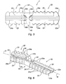
- FIG. 6 is a perspective view of another embodiment of the implant as claimed in the invention.
- FIG. 7 is a schematic view of the implant of FIG. 1 once implanted between two bones.
- FIGS. 1 to 3 show an implant 1 as claimed in the invention for realizing an arthrodesis.
- the implant 1 includes a first part 20 , with an elongated shape overall, having a longitudinal axis A, a second part 30 , also with an elongated shape overall and having a longitudinal axis B, and a central core 40 connecting the first part 20 to the second part 30 .
- the longitudinal axis A and the longitudinal axis B form between them an angle ⁇ : said angle ⁇ can vary by about 0 to 30°, for example from 10 to 20°, in particular in order to adjust the implant of the invention to the anatomy of the part of the human body to be treated, for example the foot or the hand.
- the angle ⁇ can be zero: in such a case, the first part and the second part are located in line with one another.
- the central core 40 is a solid body, the cross section of which through the plane II′ (see FIG. 2 ) perpendicular to the longitudinal axis A has approximately the form of a star with at least three points 41 , 42 , 43 : in the example shown, said star is T-shaped, the point 41 corresponding to the vertical bar of the T, each point 42 and 43 corresponding in each case to an end of the cross bar of the T.
- each point 41 , 42 , and 43 extends approximately radially from one junction point shown by the letter J in FIG. 3 , as far as up to the free respective end thereof ( 41 a , 42 a , 43 a ).
- the star could be Y-shaped overall.
- the star could include more than three points.
- the points of the star extend approximately radially from their junction point J, and are spaced apart from each other by regular or irregular angles.
- the point 41 is spaced from each point 42 and 43 by an angle of 90° and the two points 42 and 43 are spaced by an angle of 180°.
- the first part in the example shown, includes three tabs ( 21 , 22 , 23 ) each extending respectively from the free end ( 41 a , 42 a , 43 a ) of the three points ( 41 , 42 , 43 ) along the longitudinal axis A (see FIG. 1 ).
- the tabs ( 21 , 22 , 23 ) all have the overall shape of an elongated parallelepiped, the free end of which ( 21 a , 22 a , 23 a ) is in the shape of a portion of a cone.
- Such a shape of the free ends ( 21 a , 22 a , 23 a ) of the tabs ( 21 , 22 , 23 ) allows for easy insertion into the bone in which the first part 20 is intended to be inserted.
- the section of the parallelepiped, outside the region of the free end thereof, can be overall, for example, squared, rectangular, triangular, trapezoidal.
- the tabs could have the overall form of a cylinder having an ovoid or even round sectional form.
- the three tabs ( 21 , 22 , 23 ) extend in parallel with respect to each other.
- the tabs ( 21 , 22 , 23 ) could extend along the respective axes, moving slightly away from the longitudinal axis A.
- each tab 21 , 22 , 23 ) is provided with locking catches 24 : said locking catches constitute the first attachment means intended to ensure the support of the first part 20 of the implant 1 in the bone in which said first part is intended to be inserted.
- said locking catches 24 each have an edge 24 a directed toward the central core 40 : as will subsequently become clear in the description below, the direction of the edges 24 a toward the central core 40 helps to position the bone in which the first part is inserted side by side with the bone in which the second part 30 of the implant 1 is implanted.
- the three tabs ( 21 , 22 , 23 ) each have a reduced cross section ( 21 b , 22 b , 23 b ) at their junction with the central core 40 .
- Said reduced sections ( 21 b , 22 b , 23 b ) form, in particular, curvilinear cuts 44 in the central core 40 .
- Such reduced sections of the tabs, and notably the resultant curvilinear cuts 44 of the central core 40 allow the implant 1 to be bestowed upon with elasticity and a flexibility, in particular around the central core 40 , allowing the implant 1 to be easily placed into position.
- the second part 30 in the example shown, includes three legs ( 31 , 32 , 33 ) each extending respectively from the free end ( 41 a , 42 a , 43 a ) of the three points ( 41 , 42 , 43 ) of the central core 40 along the longitudinal axis B (see FIG. 1 ).
- the legs ( 31 , 32 , 33 ) extend overall in line, however along the longitudinal axis B of the three tabs ( 21 , 22 , 23 ) of the first part 20 .
- the legs ( 31 , 32 , 33 ) are all in the overall shape of an elongated parallelepiped, the free end of which ( 31 a , 32 a , 33 a ) is in the shape of a portion of a cone.
- a shape of the free ends ( 31 a , 32 a , 33 a ) of the legs ( 31 , 32 , 33 ) allows easy insertion into the bone in which the second part 30 is intended to be inserted.
- the parallelepiped section, outside the region of the free end thereof, can be overall, for example, squared, rectangular, triangular, trapezoidal.
- the legs could be in the overall form of a cylinder having an ovoid or even round form section.
- the three legs ( 31 , 32 , 33 ) extend in parallel with each other.
- the legs ( 31 , 32 , 33 ) could extend along the respective axes moving slightly away from the longitudinal axis B.
- each leg ( 31 , 32 , 33 ) is provided with locking catches 34 : said locking catches constitute the second attachment means intended to ensure the support of the second part 30 of the implant 1 in the bone in which said second part 30 is intended to be inserted.
- said locking catches 34 each have an edge 34 a directed toward the central core 40 : as will subsequently become clear in the description below, the direction of the edges 34 a toward the central core 40 allows the bone in which the second part 30 is inserted to be pressed against the bone in which the first part 20 of the implant 1 is implanted.
- the three legs ( 31 , 32 , 33 ) each have a reduced cross section ( 31 b , 32 b , 33 b ) at their junction with the central core 40 .
- Said reduced sections ( 31 b , 32 b , 33 b ) form, in particular, curvilinear cuts 44 in the central core 40 .
- curvilinear cuts 44 in the central core 40 As seen previously for the first part 20 , such reduced sections of the legs ( 31 , 32 , 33 ), and notably the resultant curvilinear cuts 44 in the central core 40 , allow the implant 1 to be bestowed upon with elasticity and flexibility, in particular around the central core 40 , allowing the implant 1 to be easily placed in position.
- the second part 30 has a length approximately equal to twice the length of the first part 20 .
- the implant 1 shown in FIGS. 1 to 5 is particularly suited for an interphalangeal arthrodesis, involving two bones (a first phalanx and a second phalanx) of different lengths.
- the first part and the second part are approximately equal in length.
- FIG. 6 a realization variant of the implant 1 as claimed in the invention is shown in which the leg of the second part 30 extending from the free end 41 a of the vertical bar of the T of the central core 40 has been dispensed with.
- the second part 30 thus includes two legs ( 32 , 33 ), extending along the longitudinal axis B.
- the implants 1 described in FIGS. 1 to 6 are preferably monobloc. They can be realized, for example, by injection molding or even by machining.
- the material suitable for realizing the implants 1 of said figures can be any material which is biocompatible, metallic or non-metallic.
- said material can be selected from amongst polyetheretherketones (PEEK), titanium, stainless steel, polylactic acids, and their mixtures. Thanks to their specific structure, the implants as claimed in the invention ensure stability of the unit, made up by the first bone, the second bone and the implant, in the three spatial directions in the position required by the surgeon, whilst having good elasticity and good flexibility making them easy to manipulate and place in position.
- FIG. 7 shows the implant 1 of FIGS. 1 to 5 once implanted, in the case of an arthrodesis concerning an articulation between two phalanges, the phalanx P 1 and the phalanx P 2 .
- the implant of FIG. 6 could be used to realize an arthrodesis in the same manner.
- the first part 20 of the implant 1 has been inserted into the medullar canal of the phalanx P 2 and the second part 30 of the implant 1 has been inserted into the medullar canal of the phalanx P 1 .
- the second part 30 being longer than the first part 20 , the second part 30 has preferably been inserted into the phalanx P 1 prior to the insertion of the first part 20 in the phalanx P 2 .
- the first part and the second part are approximately the same length and for which, for example, the angle ⁇ (see FIG. 2 ) is equal to 0°, the order in which the two parts are respectively inserted into the two phalanges to be fused can be immaterial.
- the respective locking catches ( 24 , 34 ) of the first part 20 and of the second part 30 thanks to the respective orientation of their edges ( 24 a , 34 a ), push the first bone (the phalanx P 2 ) against the second bone (the phalanx P 1 ) which, as can be seen in the figure, are placed together side by side.
- the implant 1 as claimed in the invention supports the unit made up by the phalanx P 1 , the phalanx P 2 and the implant 1 in the position determined by the surgeon, at least for the period necessary for osseous fusion between the phalanx P 1 and the phalanx P 2 , at the initial contact surface, shown by the letter C, on the figure.
Abstract
Description
Claims (12)
Applications Claiming Priority (4)
| Application Number | Priority Date | Filing Date | Title |
|---|---|---|---|
| FR10/51673 | 2010-03-09 | ||
| FR1051673 | 2010-03-09 | ||
| FR1051673A FR2957244B1 (en) | 2010-03-09 | 2010-03-09 | ARTHRODESE IMPLANT |
| PCT/FR2011/050473 WO2011110784A1 (en) | 2010-03-09 | 2011-03-08 | Arthrodesis implant |
Publications (2)
| Publication Number | Publication Date |
|---|---|
| US20130066435A1 US20130066435A1 (en) | 2013-03-14 |
| US8834572B2 true US8834572B2 (en) | 2014-09-16 |
Family
ID=42985533
Family Applications (1)
| Application Number | Title | Priority Date | Filing Date |
|---|---|---|---|
| US13/583,685 Active 2031-06-24 US8834572B2 (en) | 2010-03-09 | 2011-03-08 | Arthrodesis implant |
Country Status (12)
| Country | Link |
|---|---|
| US (1) | US8834572B2 (en) |
| EP (1) | EP2544633B1 (en) |
| JP (1) | JP5814952B2 (en) |
| CN (1) | CN102802566B (en) |
| AU (1) | AU2011225917B2 (en) |
| BR (1) | BR112012022343A2 (en) |
| CA (1) | CA2791967A1 (en) |
| EA (1) | EA022497B1 (en) |
| ES (1) | ES2531857T3 (en) |
| FR (1) | FR2957244B1 (en) |
| WO (1) | WO2011110784A1 (en) |
| ZA (1) | ZA201207174B (en) |
Cited By (12)
| Publication number | Priority date | Publication date | Assignee | Title |
|---|---|---|---|---|
| US20140309747A1 (en) * | 2011-12-12 | 2014-10-16 | Solana Surgical, Llc | Fusion Implant |
| US20150012050A1 (en) * | 2013-07-03 | 2015-01-08 | Biomet Manufacturing, Llc | Bone fusion device |
| US20150150607A1 (en) * | 2012-05-22 | 2015-06-04 | Lifenet Health | Cortical Bone Pin |
| USD745163S1 (en) * | 2014-11-13 | 2015-12-08 | Biomedical Enterprises, Inc. | Orthopedic implant |
| US9757168B2 (en) | 2015-03-03 | 2017-09-12 | Howmedica Osteonics Corp. | Orthopedic implant and methods of implanting and removing same |
| US9949774B2 (en) | 2016-05-26 | 2018-04-24 | Timothy Chen | Axial compression implant |
| US10383671B2 (en) | 2008-09-09 | 2019-08-20 | Stryker European Holdings I, Llc | Resorptive intramedullary implant between two bones or two bone fragments |
| US10470807B2 (en) | 2016-06-03 | 2019-11-12 | Stryker European Holdings I, Llc | Intramedullary implant and method of use |
| US10582957B2 (en) | 2014-09-19 | 2020-03-10 | Crossroads Extremity Systems, Llc | Bone fixation implant and means of fixation |
| US10595915B2 (en) | 2017-03-10 | 2020-03-24 | Paragon 28, Inc. | Bone implant devices, instruments and methods of use |
| US10660676B2 (en) | 2017-02-20 | 2020-05-26 | Paragon 28, Inc. | Implants, devices, instruments, systems and methods of forming and implanting |
| US11478285B2 (en) | 2005-04-14 | 2022-10-25 | Stryker European Operations Holdings Llc | Device for osteosyntheses or arthrodesis of two-bone parts, in particular of the hand and/or foot |
Families Citing this family (29)
| Publication number | Priority date | Publication date | Assignee | Title |
|---|---|---|---|---|
| FR2913876B1 (en) | 2007-03-20 | 2009-06-05 | Memometal Technologies Soc Par | OSTEOSYNTHESIS DEVICE |
| US9498273B2 (en) | 2010-06-02 | 2016-11-22 | Wright Medical Technology, Inc. | Orthopedic implant kit |
| US9072564B2 (en) | 2010-06-02 | 2015-07-07 | Wright Medical Technology, Inc. | Hammer toe implant and method |
| US9724140B2 (en) | 2010-06-02 | 2017-08-08 | Wright Medical Technology, Inc. | Tapered, cylindrical cruciform hammer toe implant and method |
| US8608785B2 (en) | 2010-06-02 | 2013-12-17 | Wright Medical Technology, Inc. | Hammer toe implant with expansion portion for retrograde approach |
| FR2980097B1 (en) * | 2011-09-16 | 2014-01-10 | Georges Kehyayan | OSTEOSYNTHESIS DEVICE |
| US9724138B2 (en) * | 2011-09-22 | 2017-08-08 | Arthrex, Inc. | Intermedullary devices for generating and applying compression within a body |
| US8945232B2 (en) | 2012-12-31 | 2015-02-03 | Wright Medical Technology, Inc. | Ball and socket implants for correction of hammer toes and claw toes |
| US9724139B2 (en) | 2013-10-01 | 2017-08-08 | Wright Medical Technology, Inc. | Hammer toe implant and method |
| EP3060145A4 (en) * | 2013-10-23 | 2017-11-15 | Extremity Medical LLC | Devices and methods for bone fixation using an intramedullary fixation implant |
| EP3068324A4 (en) | 2013-11-11 | 2017-10-04 | Mx Orthopedics, Corp. | Screws for generating and applying compression within a body |
| EP3563776A3 (en) | 2013-11-13 | 2020-08-05 | Arthrex, Inc | Staples for generating and applying compression within a body |
| US9474561B2 (en) * | 2013-11-19 | 2016-10-25 | Wright Medical Technology, Inc. | Two-wire technique for installing hammertoe implant |
| US9545274B2 (en) | 2014-02-12 | 2017-01-17 | Wright Medical Technology, Inc. | Intramedullary implant, system, and method for inserting an implant into a bone |
| US9498266B2 (en) * | 2014-02-12 | 2016-11-22 | Wright Medical Technology, Inc. | Intramedullary implant, system, and method for inserting an implant into a bone |
| US10716604B2 (en) * | 2014-07-21 | 2020-07-21 | Maurho Medical, Inc. | Bone fusing device for fusing phalanges |
| FR3024835B1 (en) * | 2014-08-18 | 2021-07-30 | In2Bones | ARTHRODESIS IMPLANT AND GRIPPING INSTRUMENT OF SUCH AN IMPLANT |
| WO2016043751A1 (en) | 2014-09-18 | 2016-03-24 | Wright Medical Technology, Inc. | Hammertoe implant and instrument |
| JP6438033B2 (en) * | 2014-12-19 | 2018-12-12 | ライト メディカル テクノロジー インコーポレイテッドWright Medical Technology, Inc. | Intramedullary implant |
| WO2016123382A1 (en) | 2015-01-28 | 2016-08-04 | Mx Orthopedics, Corp. | Self-compressing screws for generating and applying compression within a body |
| WO2016154417A1 (en) | 2015-03-24 | 2016-09-29 | Mẍ Orthopedics, Corp. | Staples for generating and applying compression within a body |
| FR3041245B1 (en) * | 2015-09-23 | 2021-06-18 | Newclip Int | INTRAMEDULAR IMPLANT FOR BLOCKING THE JOINT BETWEEN TWO PHALANGES AND ITS APPLICATION MATERIAL |
| FR3048871A1 (en) | 2016-03-16 | 2017-09-22 | Neosteo | MEDICAL IMPLANT AND ASSEMBLY COMPRISING SUCH A MEDICAL IMPLANT AND A PREHENDER OF SAID IMPLANT |
| WO2017192632A1 (en) * | 2016-05-03 | 2017-11-09 | Additive Orthopaedics, LLC | Bone fixation device and method of use |
| WO2017210695A1 (en) | 2016-06-03 | 2017-12-07 | Additive Orthopaedics, LLC | Bone fixation devices |
| WO2018023131A1 (en) | 2016-07-29 | 2018-02-01 | Additive Orthopaedics, LLC | Bone fixation device and method of use |
| WO2018188861A1 (en) * | 2017-04-11 | 2018-10-18 | Waldemar Link Gmbh & Co. Kg | Arthrodesis plate |
| FR3072015B1 (en) * | 2017-10-09 | 2022-05-20 | Adsm | MEDICAL IMPLANT FOR ARTHRODESIS |
| US11147679B2 (en) | 2018-02-05 | 2021-10-19 | Paragon Advanced Technologies, Inc. | Bone fixation device |
Citations (6)
| Publication number | Priority date | Publication date | Assignee | Title |
|---|---|---|---|---|
| DE1805665A1 (en) | 1968-09-13 | 1970-05-27 | Smidt Dr Tomislav | Atraumatic femoral neck nail |
| FR2801189A1 (en) | 1999-11-24 | 2001-05-25 | Newdeal | Bone shortening implant, especially for metatarsal bones, has anterior portion with anchoring head and posterior portion sliding into bone canal |
| US7041106B1 (en) | 2001-06-15 | 2006-05-09 | Biomet, Inc. | Interphalangeal fusion pin |
| WO2006109004A1 (en) | 2005-04-14 | 2006-10-19 | Memometal Technologies | Intramedullar osteosynthetic device of two bone parts, in particular of the hand and/or foot |
| FR2913876A1 (en) | 2007-03-20 | 2008-09-26 | Memometal Technologies Soc Par | OSTEOSYNTHESIS DEVICE |
| US8262712B2 (en) | 2006-11-16 | 2012-09-11 | New Deal | Phalangeal arthrodesis implant, surgical kit and method for manufacturing same |
Family Cites Families (2)
| Publication number | Priority date | Publication date | Assignee | Title |
|---|---|---|---|---|
| SE528323C2 (en) * | 2004-06-01 | 2006-10-17 | Medvelop Ab | Joint prosthesis |
| US20050283159A1 (en) * | 2004-06-17 | 2005-12-22 | Bouali Amara | Intramedullary osteosynthesis implant |
-
2010
- 2010-03-09 FR FR1051673A patent/FR2957244B1/en active Active
-
2011
- 2011-03-08 WO PCT/FR2011/050473 patent/WO2011110784A1/en active Application Filing
- 2011-03-08 US US13/583,685 patent/US8834572B2/en active Active
- 2011-03-08 BR BR112012022343A patent/BR112012022343A2/en not_active IP Right Cessation
- 2011-03-08 EA EA201290863A patent/EA022497B1/en not_active IP Right Cessation
- 2011-03-08 JP JP2012556569A patent/JP5814952B2/en active Active
- 2011-03-08 ES ES11712977.5T patent/ES2531857T3/en active Active
- 2011-03-08 EP EP11712977.5A patent/EP2544633B1/en active Active
- 2011-03-08 CA CA2791967A patent/CA2791967A1/en not_active Abandoned
- 2011-03-08 CN CN201180013077.7A patent/CN102802566B/en not_active Expired - Fee Related
- 2011-03-08 AU AU2011225917A patent/AU2011225917B2/en active Active
-
2012
- 2012-09-25 ZA ZA2012/07174A patent/ZA201207174B/en unknown
Patent Citations (7)
| Publication number | Priority date | Publication date | Assignee | Title |
|---|---|---|---|---|
| DE1805665A1 (en) | 1968-09-13 | 1970-05-27 | Smidt Dr Tomislav | Atraumatic femoral neck nail |
| FR2801189A1 (en) | 1999-11-24 | 2001-05-25 | Newdeal | Bone shortening implant, especially for metatarsal bones, has anterior portion with anchoring head and posterior portion sliding into bone canal |
| US7041106B1 (en) | 2001-06-15 | 2006-05-09 | Biomet, Inc. | Interphalangeal fusion pin |
| WO2006109004A1 (en) | 2005-04-14 | 2006-10-19 | Memometal Technologies | Intramedullar osteosynthetic device of two bone parts, in particular of the hand and/or foot |
| US8262712B2 (en) | 2006-11-16 | 2012-09-11 | New Deal | Phalangeal arthrodesis implant, surgical kit and method for manufacturing same |
| FR2913876A1 (en) | 2007-03-20 | 2008-09-26 | Memometal Technologies Soc Par | OSTEOSYNTHESIS DEVICE |
| WO2008129214A2 (en) | 2007-03-20 | 2008-10-30 | Memometal Technologies | Osteosynthesis device |
Non-Patent Citations (1)
| Title |
|---|
| International Search Report issued Jun. 20, 2011 re: PCT/FR2011/050473; citing: FR 2 913 876 A1, WO 2006/109004 A1, US 7,041,106 B1 and DE 1805 665 A1. |
Cited By (22)
| Publication number | Priority date | Publication date | Assignee | Title |
|---|---|---|---|---|
| US11478285B2 (en) | 2005-04-14 | 2022-10-25 | Stryker European Operations Holdings Llc | Device for osteosyntheses or arthrodesis of two-bone parts, in particular of the hand and/or foot |
| US10383671B2 (en) | 2008-09-09 | 2019-08-20 | Stryker European Holdings I, Llc | Resorptive intramedullary implant between two bones or two bone fragments |
| US9554914B2 (en) * | 2011-12-12 | 2017-01-31 | Wright Medical Technology, Inc. | Fusion implant |
| US20170100172A1 (en) * | 2011-12-12 | 2017-04-13 | Wright Medical Technology, Inc. | Fusion implant |
| US10463407B2 (en) * | 2011-12-12 | 2019-11-05 | Wright Medical Technology, Inc. | Fusion implant |
| US20140309747A1 (en) * | 2011-12-12 | 2014-10-16 | Solana Surgical, Llc | Fusion Implant |
| US10653462B2 (en) * | 2012-05-22 | 2020-05-19 | Lifenet Health | Cortical bone pin |
| US11253297B2 (en) | 2012-05-22 | 2022-02-22 | Lifenet Health | Cortical bone pin |
| US20150150607A1 (en) * | 2012-05-22 | 2015-06-04 | Lifenet Health | Cortical Bone Pin |
| US20150012050A1 (en) * | 2013-07-03 | 2015-01-08 | Biomet Manufacturing, Llc | Bone fusion device |
| US9962202B2 (en) | 2013-07-03 | 2018-05-08 | Biomet Manufacturing, Llc | Bone fusion device |
| US9517098B2 (en) * | 2013-07-03 | 2016-12-13 | Biomet Manufacturing, Llc | Bone fusion device |
| US10582957B2 (en) | 2014-09-19 | 2020-03-10 | Crossroads Extremity Systems, Llc | Bone fixation implant and means of fixation |
| USD745163S1 (en) * | 2014-11-13 | 2015-12-08 | Biomedical Enterprises, Inc. | Orthopedic implant |
| US9757168B2 (en) | 2015-03-03 | 2017-09-12 | Howmedica Osteonics Corp. | Orthopedic implant and methods of implanting and removing same |
| US10702318B2 (en) | 2015-03-03 | 2020-07-07 | Howmedica Osteonics Corp. | Orthopedic implant and methods of implanting and removing same |
| US11672576B2 (en) | 2015-03-03 | 2023-06-13 | Howmedica Osteonics Corp. | Orthopedic implant and methods of implanting and removing same |
| US9949774B2 (en) | 2016-05-26 | 2018-04-24 | Timothy Chen | Axial compression implant |
| US10470807B2 (en) | 2016-06-03 | 2019-11-12 | Stryker European Holdings I, Llc | Intramedullary implant and method of use |
| US11272966B2 (en) | 2016-06-03 | 2022-03-15 | Stryker European Operations Holdings Llc | Intramedullary implant and method of use |
| US10660676B2 (en) | 2017-02-20 | 2020-05-26 | Paragon 28, Inc. | Implants, devices, instruments, systems and methods of forming and implanting |
| US10595915B2 (en) | 2017-03-10 | 2020-03-24 | Paragon 28, Inc. | Bone implant devices, instruments and methods of use |
Also Published As
| Publication number | Publication date |
|---|---|
| WO2011110784A1 (en) | 2011-09-15 |
| EP2544633A1 (en) | 2013-01-16 |
| AU2011225917B2 (en) | 2016-04-07 |
| CA2791967A1 (en) | 2011-09-15 |
| CN102802566B (en) | 2015-03-25 |
| BR112012022343A2 (en) | 2016-07-05 |
| JP5814952B2 (en) | 2015-11-17 |
| FR2957244A1 (en) | 2011-09-16 |
| EA022497B1 (en) | 2016-01-29 |
| JP2013521091A (en) | 2013-06-10 |
| EP2544633B1 (en) | 2014-11-19 |
| ES2531857T3 (en) | 2015-03-20 |
| ZA201207174B (en) | 2013-05-29 |
| FR2957244B1 (en) | 2012-04-13 |
| CN102802566A (en) | 2012-11-28 |
| EA201290863A1 (en) | 2013-02-28 |
| US20130066435A1 (en) | 2013-03-14 |
| AU2011225917A1 (en) | 2012-10-11 |
Similar Documents
| Publication | Publication Date | Title |
|---|---|---|
| US8834572B2 (en) | Arthrodesis implant | |
| US11937860B2 (en) | Bone fixation device and method of use | |
| JP2022028930A (en) | Implant comprising curved bone contact element | |
| EP2749256B1 (en) | Ball and socket implants for correction of hammer toes and claw toes | |
| CN107548296B (en) | Implant configured for malleolus and small bone fixation | |
| US20160367298A1 (en) | Bone fixation device and method | |
| US9949773B2 (en) | Orthopedic bone plate and locking tab apparatus and method of use | |
| KR20040091735A (en) | Dynamic intervertebral implant | |
| JP7126509B2 (en) | platform fracture fixation implant | |
| GB2430625A (en) | Joint fusion peg | |
| JP7090673B2 (en) | Implants with groove patterns and soft tissue binding mechanisms | |
| CN111050703B (en) | Artificial ankle tibia element | |
| CA3054194C (en) | Implants for bridging osseous defects | |
| WO2019079856A1 (en) | Implant for tibial fractures | |
| CN111683611B (en) | Implants and methods for the treatment of Charcol's foot and other conditions | |
| JP2020527984A (en) | Femur fracture fixation device with posterior support | |
| US20200390563A1 (en) | Medical arthrodesis implant | |
| CN106999218A (en) | Closure distal femoral osteotomy fixed appliance | |
| WO2013086174A1 (en) | Bone-conserving orthopedic augments |
Legal Events
| Date | Code | Title | Description |
|---|---|---|---|
| AS | Assignment |
Owner name: SYNCHRO MEDICAL, FRANCE Free format text: ASSIGNMENT OF ASSIGNORS INTEREST;ASSIGNORS:AVEROUS, CHRISTOPHE;CERMOLACCE, CHRISTOPHE;DETERME, PATRICE;AND OTHERS;SIGNING DATES FROM 20120929 TO 20121010;REEL/FRAME:029332/0067 |
|
| STCF | Information on status: patent grant |
Free format text: PATENTED CASE |
|
| FEPP | Fee payment procedure |
Free format text: SURCHARGE FOR LATE PAYMENT, LARGE ENTITY (ORIGINAL EVENT CODE: M1554) |
|
| MAFP | Maintenance fee payment |
Free format text: PAYMENT OF MAINTENANCE FEE, 4TH YEAR, LARGE ENTITY (ORIGINAL EVENT CODE: M1551) Year of fee payment: 4 |
|
| AS | Assignment |
Owner name: ADSM, FRANCE Free format text: CHANGE OF NAME;ASSIGNOR:SYNCHRO MEDICAL;REEL/FRAME:058687/0262 Effective date: 20200717 |
|
| FEPP | Fee payment procedure |
Free format text: ENTITY STATUS SET TO SMALL (ORIGINAL EVENT CODE: SMAL); ENTITY STATUS OF PATENT OWNER: SMALL ENTITY |
|
| MAFP | Maintenance fee payment |
Free format text: PAYMENT OF MAINTENANCE FEE, 8TH YR, SMALL ENTITY (ORIGINAL EVENT CODE: M2552); ENTITY STATUS OF PATENT OWNER: SMALL ENTITY Year of fee payment: 8 |