US8826964B2 - Lateral restraint assemblies, movable partitions including lateral restraint devices and related methods - Google Patents
Lateral restraint assemblies, movable partitions including lateral restraint devices and related methods Download PDFInfo
- Publication number
- US8826964B2 US8826964B2 US13/931,158 US201313931158A US8826964B2 US 8826964 B2 US8826964 B2 US 8826964B2 US 201313931158 A US201313931158 A US 201313931158A US 8826964 B2 US8826964 B2 US 8826964B2
- Authority
- US
- United States
- Prior art keywords
- movable partition
- lateral restraint
- partition
- elongated member
- overhead track
- Prior art date
- Legal status (The legal status is an assumption and is not a legal conclusion. Google has not performed a legal analysis and makes no representation as to the accuracy of the status listed.)
- Active
Links
Images


Classifications
-
- E—FIXED CONSTRUCTIONS
- E06—DOORS, WINDOWS, SHUTTERS, OR ROLLER BLINDS IN GENERAL; LADDERS
- E06B—FIXED OR MOVABLE CLOSURES FOR OPENINGS IN BUILDINGS, VEHICLES, FENCES OR LIKE ENCLOSURES IN GENERAL, e.g. DOORS, WINDOWS, BLINDS, GATES
- E06B3/00—Window sashes, door leaves, or like elements for closing wall or like openings; Layout of fixed or moving closures, e.g. windows in wall or like openings; Features of rigidly-mounted outer frames relating to the mounting of wing frames
- E06B3/32—Arrangements of wings characterised by the manner of movement; Arrangements of movable wings in openings; Features of wings or frames relating solely to the manner of movement of the wing
- E06B3/48—Wings connected at their edges, e.g. foldable wings
-
- E—FIXED CONSTRUCTIONS
- E05—LOCKS; KEYS; WINDOW OR DOOR FITTINGS; SAFES
- E05D—HINGES OR SUSPENSION DEVICES FOR DOORS, WINDOWS OR WINGS
- E05D15/00—Suspension arrangements for wings
- E05D15/26—Suspension arrangements for wings for folding wings
-
- E—FIXED CONSTRUCTIONS
- E05—LOCKS; KEYS; WINDOW OR DOOR FITTINGS; SAFES
- E05D—HINGES OR SUSPENSION DEVICES FOR DOORS, WINDOWS OR WINGS
- E05D15/00—Suspension arrangements for wings
- E05D15/06—Suspension arrangements for wings for wings sliding horizontally more or less in their own plane
- E05D15/0621—Details, e.g. suspension or supporting guides
- E05D15/0626—Details, e.g. suspension or supporting guides for wings suspended at the top
- E05D15/063—Details, e.g. suspension or supporting guides for wings suspended at the top on wheels with fixed axis
-
- E—FIXED CONSTRUCTIONS
- E06—DOORS, WINDOWS, SHUTTERS, OR ROLLER BLINDS IN GENERAL; LADDERS
- E06B—FIXED OR MOVABLE CLOSURES FOR OPENINGS IN BUILDINGS, VEHICLES, FENCES OR LIKE ENCLOSURES IN GENERAL, e.g. DOORS, WINDOWS, BLINDS, GATES
- E06B3/00—Window sashes, door leaves, or like elements for closing wall or like openings; Layout of fixed or moving closures, e.g. windows in wall or like openings; Features of rigidly-mounted outer frames relating to the mounting of wing frames
- E06B3/92—Doors or windows extensible when set in position
- E06B3/94—Doors of the bellows type
-
- E—FIXED CONSTRUCTIONS
- E05—LOCKS; KEYS; WINDOW OR DOOR FITTINGS; SAFES
- E05D—HINGES OR SUSPENSION DEVICES FOR DOORS, WINDOWS OR WINGS
- E05D15/00—Suspension arrangements for wings
- E05D15/06—Suspension arrangements for wings for wings sliding horizontally more or less in their own plane
- E05D15/0621—Details, e.g. suspension or supporting guides
- E05D15/0626—Details, e.g. suspension or supporting guides for wings suspended at the top
- E05D15/0652—Tracks
-
- E—FIXED CONSTRUCTIONS
- E05—LOCKS; KEYS; WINDOW OR DOOR FITTINGS; SAFES
- E05D—HINGES OR SUSPENSION DEVICES FOR DOORS, WINDOWS OR WINGS
- E05D15/00—Suspension arrangements for wings
- E05D15/06—Suspension arrangements for wings for wings sliding horizontally more or less in their own plane
- E05D15/08—Suspension arrangements for wings for wings sliding horizontally more or less in their own plane consisting of two or more independent parts movable each in its own guides
-
- E—FIXED CONSTRUCTIONS
- E05—LOCKS; KEYS; WINDOW OR DOOR FITTINGS; SAFES
- E05Y—INDEXING SCHEME RELATING TO HINGES OR OTHER SUSPENSION DEVICES FOR DOORS, WINDOWS OR WINGS AND DEVICES FOR MOVING WINGS INTO OPEN OR CLOSED POSITION, CHECKS FOR WINGS AND WING FITTINGS NOT OTHERWISE PROVIDED FOR, CONCERNED WITH THE FUNCTIONING OF THE WING
- E05Y2900/00—Application of doors, windows, wings or fittings thereof
- E05Y2900/10—Application of doors, windows, wings or fittings thereof for buildings or parts thereof
- E05Y2900/13—Application of doors, windows, wings or fittings thereof for buildings or parts thereof characterised by the type of wing
- E05Y2900/132—Doors
-
- Y—GENERAL TAGGING OF NEW TECHNOLOGICAL DEVELOPMENTS; GENERAL TAGGING OF CROSS-SECTIONAL TECHNOLOGIES SPANNING OVER SEVERAL SECTIONS OF THE IPC; TECHNICAL SUBJECTS COVERED BY FORMER USPC CROSS-REFERENCE ART COLLECTIONS [XRACs] AND DIGESTS
- Y10—TECHNICAL SUBJECTS COVERED BY FORMER USPC
- Y10T—TECHNICAL SUBJECTS COVERED BY FORMER US CLASSIFICATION
- Y10T29/00—Metal working
- Y10T29/49—Method of mechanical manufacture
- Y10T29/49826—Assembling or joining
-
- Y—GENERAL TAGGING OF NEW TECHNOLOGICAL DEVELOPMENTS; GENERAL TAGGING OF CROSS-SECTIONAL TECHNOLOGIES SPANNING OVER SEVERAL SECTIONS OF THE IPC; TECHNICAL SUBJECTS COVERED BY FORMER USPC CROSS-REFERENCE ART COLLECTIONS [XRACs] AND DIGESTS
- Y10—TECHNICAL SUBJECTS COVERED BY FORMER USPC
- Y10T—TECHNICAL SUBJECTS COVERED BY FORMER US CLASSIFICATION
- Y10T292/00—Closure fasteners
- Y10T292/37—Portable securer plate or bar
- Y10T292/379—Sliding holding member
- Y10T292/388—Sliding catch
Definitions
- the present invention relates to movable partitions and, more particularly, to systems, apparatuses and methods for preventing lateral displacement of one or more portions of such partitions.
- Movable partitions are utilized in numerous situations and environments for a variety of purposes. Such partitions may include, for example, foldable or collapsible doors configured to close off an opening in order to enclose a room or to subdivide a single large room into one or more smaller rooms. The subdivision of a larger area may be desired, for example, to accommodate the simultaneous meeting of multiple groups. In such applications movable partitions are useful, among other things, for providing privacy and noise reduction.
- Movable partitions may also be used to act as a security barrier, a fire barrier or as both.
- the movable partition may be configured to automatically close upon the occurrence of a predetermined event such as the actuation of an associated alarm.
- one or more movable partitions may be configured as a fire door or barrier wherein each door is formed with a plurality of panels connected to each other by way of hinge mechanisms. The hinged connection of the panels allows the door to fold-up in a compact unit on one side of the opening or it may be stored in a pocket formed within a wall and being designed to conceal the door and preserve the aesthetics of the room where the door is installed.
- the door When deployment of the door is necessary, the door is driven by a motor along a track (the track often being incorporated into the header above the door), until the leading edge of the door, often defined by a component called a lead post, complementarily engages a mating receptacle.
- a mating receptacle may be referred to as a jamb or a door post when formed in a fixed structure (such as a wall), or as mating lead post when formed in another door or movable partition.
- the lead post when properly engaged with the door jamb (or the mating lead post), allows corresponding latching mechanisms to engage if desired, and helps to provide a desired seal (e.g., a seal with respect to airflow, sound waves or both).
- the door seal may be broken, for example, if the lower edge of the door is laterally displaced relative to the top edge of the door.
- Such lateral displacement of the lower edge of the door can be caused, for example, by a draft created by a fire, an improperly balanced HVAC system, or simply by a person pushing on the door.
- smoke and flames may intrude around the door if the door is being used as a fire barrier.
- a person may sufficiently displace the door to enable that person, or another, to slide or crawl underneath the door. At a minimum, displacement of the base of the door is unsightly and significantly reduces the door's effectiveness as a privacy screen and noise barrier.
- a track disposed in the floor can pose a safety issue, regardless of whether it protrudes above the floor or is recessed within the floor, potentially resulting in a person twisting an ankle or tripping and falling.
- a track may act as a significant obstacle for wheeled conveyances.
- a guide track being exposed when the associated door is in a retracted state, is prone to damage and may act as a collection point for dirt and debris.
- apparatuses and systems are provided herein to substantially secure a movable partition from lateral displacement.
- methods, apparatuses and systems are provided that substantially maintain the lateral position of a lower edge of a movable partition in order to maintain a seal formed by the partition without the need to employ a track or other structure disposed within a floor over which the partition traverses.
- Embodiments of the present invention include movable partitions and devices, methods and systems that help to limit or prevent lateral displacement of movable partitions.
- a movable partition is provided that includes a first structure having a first plurality of panels, each panel being hingedly coupled to an adjacent panel, the first structure being supported from an overhead track at a first location.
- the movable partition further includes a second structure having a second plurality of panels, each panel being hingedly coupled to an adjacent panel, the second structure being supported from the overhead track from a second location, the second location being laterally spaced from the first location.
- At least one lateral restraint device is supported from the overhead track at a location between the first location and the second location.
- the at least one lateral restraint device includes a trolley disposed in a channel of the overhead track and an elongated member coupled with the trolley and extending away from the trolley to a location proximate a lower edge of the first structure and a lower edge of the second structure.
- a method of restraining lateral movement of a movable partition includes suspending a first structure from a support structure, wherein the first structure includes a first plurality of panels wherein each panel is hingedly coupled to an adjacent panel.
- a second structure is also supported from the support structure at a laterally spaced location relative to the first structure, the second structure including a second plurality of hingedly coupled panels.
- At least one elongated member is supported from the support structure along an axis extending away from the support structure and between the first structure and the second structure. The elongated member is substantially restrained from being laterally displaced toward either the first structure or the second structure.
- a device for preventing lateral displacement of one or more structures in a movable partition includes a trolley and an elongated member coupled with and extending from the trolley.
- the trolley includes a structural member and a first plurality of roller elements coupled with the structural member on a first side thereof. At least two roller elements of the first plurality have rotational axes lying in a first plane and at least one roller element of the first plurality has a rotational axis lying outside of the first plane.
- a second plurality of roller elements is coupled with the structural member on a second side thereof.
- At least two roller elements of the second plurality having rotational axes lying in the first plane and at least one roller element of the second plurality has a rotational axis lying outside of the first plane.
- the trolley further includes a third plurality of roller elements coupled with the structural member. The rotational axes of each of the third plurality of roller elements are angularly displaced relative to the rotational axes of each of the first plurality of roller elements.
- FIG. 1 is an elevation view of a movable partition in accordance with one embodiment of the present invention
- FIG. 2 is a plan view of the movable partition shown in FIG. 1 ;
- FIG. 3 is a partial cross-sectional view of a partition including an overhead track and a lateral restraint device taken along section lines 3 - 3 and in accordance with an embodiment of the present invention
- FIG. 4 is a perspective view of the overhead track and lateral restraint device shown in FIG. 3 ;
- FIG. 5 is another perspective view of the overhead track and lateral restraint device shown in FIG. 3 ;
- FIG. 6 is a partial cross-sectional view taken along section lines 6 - 6 in FIG. 3 ;
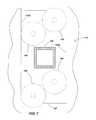
- FIG. 7 is a detail view of certain components of a lateral restraint device as indicated by section lines 7 - 7 in FIG. 3 .
- the partition 100 may be in the form of folding door.
- the partition 100 may be used, for example, as a security door, a fire barrier or as both.
- the partition need not be utilized as a fire or security barrier, but may be used, for example, to subdivide a larger space into smaller rooms or areas or it may be used as a sound barrier.
- the partition 100 may be formed with a plurality of panels 102 that are connected to one another with hinges 104 or other hinge-like structures in an alternating pattern of panel 102 and hinge 104 .
- the hinged connection of the individual panels 102 enables the panels to fold relative to each other in an accordion or a plicated manner such that the partition 100 may be compactly stored, such as in a pocket 106 formed in a wall 108 A of a building when the partition is in a retracted or folded state.
- the partition 100 When in a deployed state, the partition 100 may extend from one wall 108 A to a second wall 108 B to act as a barrier (e.g., a fire or security barrier) or to divide one area or room into multiple rooms 110 A and 110 B.
- a barrier e.g., a fire or security barrier
- the partition 100 When it is desired to deploy the partition 100 from a stowed condition to an extended position, for example, to secure an area during a fire, the partition 100 may be motivated along an overhead track 112 across the space to provide an appropriate barrier.
- a leading edge of the partition 100 shown as a male lead post 114 , may complementarily or matingly engage with a jamb or door post 116 that may, for example, be formed in a wall 108 B of a building.
- the partition 100 may include a first barrier or structure 118 A and a second barrier or structure 118 B, each including a plurality of panels 102 coupled with one another by way of hinges 104 or hinge-like structures.
- the second structure 118 B is laterally spaced from the first structure 118 A.
- Such a configuration may be utilized, for example, as a fire door wherein one structure (e.g., structure 118 A) acts as a primary fire and smoke barrier, a space 120 between the two structures 118 A and 118 B acts as an insulator or a buffer zone, and the other structure (e.g., structure 118 B) acts as a secondary fire and smoke barrier.
- Such a configuration may also be useful in providing an acoustical barrier when the partition is used to subdivide a larger space into multiple, smaller rooms.
- the structures 118 A and 118 B are each individually suspended from the overhead track 112 .
- the track 112 may have multiple elongated channels formed therein such that one structure 118 A is suspended from, and longitudinally displaced along, a first channel while the second structure 118 B is suspended from, and longitudinally displaced along, a second, separate channel.
- multiple individual tracks may be located in or on the ceiling or other supporting structure.
- Various means may be used to displace the partition 100 from a stowed condition to a deployed condition and vice versa.
- it may be displaced manually (i.e., by an individual pushing or pulling it along the track 112 ).
- an appropriate actuator may be used to displace the partition 100 .
- a drive may be used to motivate the partition 100 between a deployed and a retracted state or vice versa.
- a drive may include an electric motor 122 coupled to a pulley or gear 123 configured to drive a transmission member such as a belt or chain 124 .
- a portion of the belt or chain 124 may be coupled to a trolley 125 that is configured to ride along the track 112 .
- the trolley 125 may be coupled to a component of the partition 100 such as, for example, the lead post 114 .
- actuation of the motor 122 and belt or chain 124 in a first direction results in displacement of the trolley 125 and lead post 114 so that the partition 100 may be deployed.
- Actuation of the motor 122 and belt or chain 124 in a second direction results in displacement of the trolley 125 and lead post 114 so that the partition 100 may be retracted.
- the partition 100 may include a switch or actuator 128 , sometimes referred to as “panic hardware.” Actuation of the panic hardware 128 enables a person located on one side of the partition 100 (e.g., in room 110 A) to cause the partition 100 to open if it is closed, or to stop while it is closing, so as to provide access through the barrier formed by the partition 100 for a predetermined amount of time.
- a switch or actuator 128 sometimes referred to as “panic hardware.” Actuation of the panic hardware 128 enables a person located on one side of the partition 100 (e.g., in room 110 A) to cause the partition 100 to open if it is closed, or to stop while it is closing, so as to provide access through the barrier formed by the partition 100 for a predetermined amount of time.
- a two-door, or bi-part partition configuration may be utilized wherein two similarly configured partitions extend across a space and join together to form an appropriate barrier as will be appreciated by those of ordinary skill in the art.
- a multi-part configuration may be employed wherein multiple partitions join at a central door post when each is in an extended state.
- the lower edges of the partitions 100 may be laterally displaced such that a substantial gap may be formed between the lower edges of the structures 118 A and 118 B and the floor or other surface over which they pass.
- displacement may occur due to, for example, a draft from a fire, an imbalanced HVAC (heating, ventilation and air conditioning) system, or from some other external force being applied to one of the structures 118 A and 118 B.
- one or more lateral restraint devices 130 may be associated with the movable partition 100 .
- the lateral restraint device 130 may include a trolley 140 (separate and distinct from the trolley 125 described above) having rollers 142 or sliders coupled with a structural member 143 .
- the rollers 142 may be disposed in a central channel 144 of the track 112 and configured to roll or slide along the length of the channel 144 .
- a bar or other elongated member 146 is coupled with the trolley 140 and extends downwardly from the trolley 140 through an opening 148 in the lower portion of the track 112 such that the elongated member 146 is positioned between the two laterally spaced barriers or structures 118 A and 118 B.
- each of the laterally spaced structures 118 A and 118 B include hingedly connected panels 102 that are supported from channels 150 and 152 of the overhead track 112 by, for example, associated rollers 154 or sliding elements.
- the elongated member 146 may be coupled with a panel 102 or a hinge 104 of either, or both, of the structures 118 A and 118 B by an appropriate coupling member.
- a chain 156 (or a cable, rope or similar component) may be coupled between the elongated member 146 and a hinge 104 or panel 102 of either or both of the structures 118 A and 118 B.
- a substantially rigid bracket 158 may be coupled between the elongated member 146 and a hinge 104 or panel 102 of either or both of the structures 118 A and 118 B.
- a bracket 158 may include, or be similar to the brackets used in conjunction with the lateral restraint device described in U.S. patent application Ser. No. 11/934,566, now U.S. Pat. No. 7,931,067, issued Apr. 26, 2011, entitled MOVABLE PARTITIONS WITH LATERAL RESTRAINT DEVICES AND RELATED METHODS, previously incorporated by reference.
- the coupling of the elongated member 146 with one or both of the barriers or structures 118 A and 118 B provides a motivating force to displace the lateral resistance device 130 during opening of closing of the partition 100 such that the lateral restraint device 130 remains proximate associated panels 102 and/or hinges 104 of the structures 118 A and 118 B.
- the elongated member 146 will likewise be displaced along the track 112 .
- the trolley 140 includes multiple roller elements 142 on opposing sides of the trolley 140 . More specifically, the trolley 140 is positioned generally along a centerline 160 of the partition 100 such that a plurality of roller elements 142 are disposed on one side of the centerline 160 and a plurality of roller elements 142 are disposed on the opposite side of the centerline 160 . In the embodiment shown in FIGS. 3-6 , there are four roller elements 142 disposed on each side of the trolley 140 . However, in other embodiments, a different number of roller elements 142 may be utilized.
- roller elements 142 on a given side of the trolley 140 are offset relative to the other roller elements 142 .
- roller elements 142 A and 142 C have rotational centers or axes lying within a first common plane (represented by axis 162 ) while roller elements 142 B and 142 D have rotational centers or axes lying along a second plane (represented by axis 164 ) that is offset (vertically offset in the orientation shown in FIG. 6 ) relative to the first axis 162 .
- roller elements 142 on the opposing side of the trolley 140 may be configured in a similar matter such that, for example, various roller elements 142 have rotational axes that lie in the first plane 162 and other roller elements 142 have rotational axes that lie in the second plane 164 .
- two of the roller elements i.e., 142 A and 142 C
- two of the roller elements are in contact with, and ride along, a lower, inside surface 166 of the central channel 144 .
- the use of multiple roller elements that are in contact with the lower, inside surface 166 of the central channel 144 helps to stabilize the lateral restrain device 130 from pivoting at or near the point of the trolley 140 .
- the lower portion of the elongated member could be easily angularly displaced in a direction along the path of the partition (i.e., to the right or the left as viewed in FIG. 6 ).
- two of the roller elements do not contact the lower, inside surface 166 , but rather, are within a specified tolerance of, or even contact, an upper inside surface 167 of the central channel 144 (as indicated by dashed lines). This helps to prevent, or at least limit, potential angular displacement of the elongated member 146 in a direction substantially orthogonal to the path of the partition 100 (i.e., to the right or left as viewed in FIG. 3 ).
- additional roller elements 168 or sliding elements may be coupled, for example, to a bottom portion of the structural member 143 .
- the additional roller elements 168 are orientated to lie in a plane that is substantially orthogonal to the other roller elements 142 coupled to the trolley 140 .
- the various roller elements 142 and 168 may be angled, canted or exhibit other orientations and still provide the desired functionality as is described with respect to the currently contemplated embodiment.
- the additional roller elements 168 are configured to abut and roll against opposing edge surfaces 170 A and 170 B of the central opening 148 .
- One advantage of using the additional rollers 168 is that they help avoid angular displacement of the elongated member 146 in a direction substantially orthogonal to the path of the partition 100 (i.e., to the right or left as viewed in FIG. 3 ).
- the additional rollers 168 may be used in addition to, or in place of, the upper roller elements (i.e., 142 B and 142 D) to help prevent or limit the angular displacement of the elongated member 146 .
- the use of the additional roller elements 168 also helps to prevent the trolley 140 and associated roller elements 142 from being twisted (e.g., about an axis extending substantially through the height—as viewed in the drawings—of the elongated member 146 ) and helps prevent the trolley 140 from becoming bound within the central channel 144 of the track 112 .
- the lateral displacement device 130 provides a structural member (e.g., elongated member 146 ) positioned between the two laterally spaced structures 118 A and 118 B and which, while displaceable along the track 112 , is substantially laterally constrained.
- a structural member e.g., elongated member 146
- a chain 156 is used to coupled a structure (e.g., 118 A) with the elongated member 146
- a structure e.g., 118 A
- the structure will become displaced until it contacts the elongated member 146 .
- the elongated member 146 will then resist further displacement due to its coupling with the trolley 140 , the trolley 140 being configured to prevent or limit angular displacement of the elongated member 146 as described hereinabove. It is noted that while the barriers or structures 118 A and 118 B may be laterally displaced in such an embodiment until they contact the elongated member 146 , such displacement is minimal (e.g., a few inches) and does not substantially effect the ability of the partition 100 to perform its intended function as a barrier.
- a bracket 158 or substantially rigid coupling is formed between a structure (e.g., 118 A) and the elongated member 146 , when a lateral force is applied to the structure (e.g., 118 A), the force will be transmitted through the bracket 158 to the elongated member 146 , which will resist the force and limit displacement of the structure (e.g., 118 A).
- the lateral restraint device 130 prevents lateral displacement of the barriers or structures 118 A and 118 B primarily at the locations where the lateral restraint device 130 is installed. In other words, at a longitudinal distance (i.e., along the pathway of the partition 100 ) from the lateral restraint device 130 , a barrier or structure 118 A or 118 B will likely experience some lateral displacement. Thus, to limit lateral displacement of the barriers or structures 118 A and 118 B along their entire lengths (when in an extended state), multiple lateral restraint devices 130 may be installed at desired frequencies or distances from one another (depending, for example, on the extended length of the partition 100 ) as indicated in FIG. 2 .
- the point of maximum potential lateral displacement of a barrier or structure 118 A or 118 B will be at a midpoint between two adjacent lateral restraint devices 130 .
- the maximum allowable lateral displacement of any portion of the partition one can design a partition with an appropriate number of longitudinally spaced lateral restraint devices 130 .
- the lateral restraint devices 130 may be incorporated with a system such as is described in Ser. No. 11/652,446, now U.S. Pat. No. 7,926,538, issued Apr. 19, 2011, entitled LATERAL RESTRAINT FOR A MOVABLE PARTITION, MOVABLE PARTITIONS INCORPORATING SAME AND RELATED METHODS.
- a cable or other member may be disposed between the two barriers or structures 118 A and 118 B at a location proximate the bottom edges thereof and extend the length of the partition 100 when in a deployed or extended state.
- such a cable may be slidably coupled to (or, in another embodiment, positioned adjacent to) the elongated members 146 effectively providing a collapsible framework within the partition 100 between the laterally spaced barriers or structures 118 A and 118 B.
- the lateral restrain device 130 may also include a roller assembly 180 coupled to a lower end of the elongated structure 146 .
- the roller assembly 180 may include a wheel or other roller element 182 configured to contact and roll along a floor 184 or other surface over which the partition 100 is disposed.
- the roller assembly 180 may additionally include components that help the roller element 182 to maintain contact with the floor 184 as it rolls there across even though the floor 184 may exhibit undulations or elevation changes.
- the roller assembly 180 may include a constant force mechanism such as that which is described in U.S. patent application Ser. No. 11/796,325, now U.S. Pat. No. 7,740,046, issued Jun.
- Such a constant force mechanism may utilize linear actuators and sensors to maintain a desired force between the roller element 182 and the floor 184 , even when the elevation of the floor 184 deviates substantially along the pathway of the partition 100 .
- such a constant force mechanism may include a biasing member, such as a spring, to continually bias the roller element 182 against the floor 184 with a substantially constant force.
- Maintaining contact between the floor 184 and the roller element 182 provides additional support to the elongated member 146 to keep it from being laterally displaced.
- the elongated member 146 essentially becomes “wedged” between the floor 184 and the overhead track 112 and will resist lateral displacement.
- the roller assembly 180 may include a caster or similar mechanism that enables the roller element 182 to pivot or swivel relative to the elongated member 146 such that the roller element 182 may change directions concurrently with a change in direction of the partition 100 (e.g., from extension to retraction) without binding.
- the roller assembly 182 may include a directional control mechanism such as is described in the aforementioned U.S. patent application Ser. No. 11/796,325. The directional control mechanism may be used, for example, to further help maintain the elongated member 146 (and the section of partition 100 , with which it is associated) in a substantially plumb orientation, again preventing or limiting the lateral displacement of the door.
Abstract
Description
Claims (18)
Priority Applications (1)
| Application Number | Priority Date | Filing Date | Title |
|---|---|---|---|
| US13/931,158 US8826964B2 (en) | 2006-11-03 | 2013-06-28 | Lateral restraint assemblies, movable partitions including lateral restraint devices and related methods |
Applications Claiming Priority (6)
| Application Number | Priority Date | Filing Date | Title |
|---|---|---|---|
| US85659706P | 2006-11-03 | 2006-11-03 | |
| US11/796,325 US7740046B2 (en) | 2007-04-27 | 2007-04-27 | Method, apparatus and system for controlling a movable partition |
| US11/934,566 US7931067B2 (en) | 2006-11-03 | 2007-11-02 | Movable partitions with lateral restraint devices and related methods |
| US11/951,901 US8087444B2 (en) | 2006-11-03 | 2007-12-06 | Movable partitions with lateral restraint devices and related methods |
| US13/333,584 US8479798B2 (en) | 2006-11-03 | 2011-12-21 | Lateral restraint assemblies and movable partitions including lateral restraint devices |
| US13/931,158 US8826964B2 (en) | 2006-11-03 | 2013-06-28 | Lateral restraint assemblies, movable partitions including lateral restraint devices and related methods |
Related Parent Applications (1)
| Application Number | Title | Priority Date | Filing Date |
|---|---|---|---|
| US13/333,584 Continuation US8479798B2 (en) | 2006-11-03 | 2011-12-21 | Lateral restraint assemblies and movable partitions including lateral restraint devices |
Publications (2)
| Publication Number | Publication Date |
|---|---|
| US20130284382A1 US20130284382A1 (en) | 2013-10-31 |
| US8826964B2 true US8826964B2 (en) | 2014-09-09 |
Family
ID=40328986
Family Applications (3)
| Application Number | Title | Priority Date | Filing Date |
|---|---|---|---|
| US11/951,901 Expired - Fee Related US8087444B2 (en) | 2006-11-03 | 2007-12-06 | Movable partitions with lateral restraint devices and related methods |
| US13/333,584 Active US8479798B2 (en) | 2006-11-03 | 2011-12-21 | Lateral restraint assemblies and movable partitions including lateral restraint devices |
| US13/931,158 Active US8826964B2 (en) | 2006-11-03 | 2013-06-28 | Lateral restraint assemblies, movable partitions including lateral restraint devices and related methods |
Family Applications Before (2)
| Application Number | Title | Priority Date | Filing Date |
|---|---|---|---|
| US11/951,901 Expired - Fee Related US8087444B2 (en) | 2006-11-03 | 2007-12-06 | Movable partitions with lateral restraint devices and related methods |
| US13/333,584 Active US8479798B2 (en) | 2006-11-03 | 2011-12-21 | Lateral restraint assemblies and movable partitions including lateral restraint devices |
Country Status (5)
| Country | Link |
|---|---|
| US (3) | US8087444B2 (en) |
| AU (1) | AU2008333859B2 (en) |
| CA (1) | CA2706112C (en) |
| NZ (1) | NZ585783A (en) |
| WO (1) | WO2009073771A1 (en) |
Cited By (4)
| Publication number | Priority date | Publication date | Assignee | Title |
|---|---|---|---|---|
| US9995073B2 (en) * | 2014-02-10 | 2018-06-12 | Dynamic Closures Corporation | Folding door trolley |
| US10822863B2 (en) | 2018-05-02 | 2020-11-03 | Pella Corporation | Sliding fenestration unit with coplanar panels |
| US11286709B2 (en) | 2019-11-06 | 2022-03-29 | Pella Corporation | Coplanar bi-fold and sliding door |
| US11920403B2 (en) | 2019-01-09 | 2024-03-05 | Pella Corporation | Sliding and pivot fenestration unit |
Families Citing this family (25)
| Publication number | Priority date | Publication date | Assignee | Title |
|---|---|---|---|---|
| US7931067B2 (en) * | 2006-11-03 | 2011-04-26 | Won-Door Corporation | Movable partitions with lateral restraint devices and related methods |
| US7740046B2 (en) | 2007-04-27 | 2010-06-22 | Won-Door Corporation | Method, apparatus and system for controlling a movable partition |
| US8087444B2 (en) | 2006-11-03 | 2012-01-03 | Won-Door Corporation | Movable partitions with lateral restraint devices and related methods |
| US7926538B2 (en) * | 2007-01-11 | 2011-04-19 | Won-Door Corporation | Lateral restraint for a movable partition, movable partitions incorporating same and related methods |
| US20110000625A1 (en) * | 2009-07-02 | 2011-01-06 | Won-Door Corporation | Movable partitions, leading end assemblies for movable partitions and related methods |
| US8278862B2 (en) * | 2009-07-10 | 2012-10-02 | Won-Door Corporation | Motor control systems, foldable partitions employing motor control systems, methods of monitoring the operation of electric motors and foldable partitions |
| US8240354B2 (en) | 2010-04-12 | 2012-08-14 | Won-Door Corporation | Movable partition systems and components thereof including chain guide structures, and methods of forming and installing same |
| US8967225B2 (en) | 2010-08-18 | 2015-03-03 | Won-Door Corporation | Leading end assemblies for movable partitions and related methods |
| US8627618B2 (en) | 2010-08-18 | 2014-01-14 | Tracy M. Knight | Closure assemblies for movable partitions, movable partition systems including closure assemblies and related methods |
| US9074420B2 (en) | 2011-05-31 | 2015-07-07 | Won-Door Corporation | Methods, apparatuses, and systems for resisting lateral displacement of movable partitions |
| US8960257B2 (en) | 2011-05-31 | 2015-02-24 | Won-Door Corporation | Methods, apparatuses, and systems for controlling lateral displacement of a movable partition |
| US8544524B2 (en) * | 2011-06-21 | 2013-10-01 | Won-Door Corporation | Leading end assemblies for movable partitions including sensor assemblies, movable partition systems including sensor assemblies and related methods |
| US8534341B2 (en) | 2011-06-27 | 2013-09-17 | Won-Door Corporation | Movable partition systems and components thereof, methods if installing movable partition systems, and methods of moving a movable partition |
| US9145723B2 (en) | 2011-07-14 | 2015-09-29 | Won-Door Corporation | Movable partition systems and header structures and components thereof, and related methods of installation |
| US8567472B2 (en) | 2011-07-18 | 2013-10-29 | Won-Door Corporation | Wire trolleys, movable partition systems including such wire trolleys, and related methods |
| US8448687B2 (en) | 2011-07-18 | 2013-05-28 | Won-Door Corporation | Wire supports, movable partition systems including such wire supports, and related methods |
| US9732546B2 (en) | 2011-10-18 | 2017-08-15 | Won-Door Corporation | Chain tensioners for movable partition systems, movable partition systems including such chain tensioners, and related methods |
| CN103291190B (en) * | 2013-06-25 | 2016-01-20 | 江苏金秋竹集团有限公司 | A kind of lateral sliding door |
| WO2015017671A2 (en) * | 2013-08-01 | 2015-02-05 | Urbaneer LLC | Apparatus and method for reconfigurable space |
| US9217273B2 (en) | 2014-01-07 | 2015-12-22 | Target Brands, Inc. | Apparatus for restricting access to a retail store aisle |
| US10100573B2 (en) * | 2014-09-08 | 2018-10-16 | Clean Energy Fuels Corp. | Natural gas vehicle maintenance separation and containment system |
| US11648326B2 (en) * | 2016-02-04 | 2023-05-16 | Xenex Disinfection Services Inc. | Cabinets for disinfecting objects |
| CN110607964B (en) * | 2019-09-25 | 2021-01-05 | 中誉长青建设有限公司 | Fixing device of window is opened in electronic fire control |
| USD944020S1 (en) * | 2019-10-03 | 2022-02-22 | Molo Design, Ltd. | Adjustable partition |
| USD951662S1 (en) * | 2019-10-03 | 2022-05-17 | Molo Design, Ltd. | Adjustable partition |
Citations (118)
| Publication number | Priority date | Publication date | Assignee | Title |
|---|---|---|---|---|
| US684130A (en) | 1900-12-31 | 1901-10-08 | Albert Taubert | Screen. |
| US1205707A (en) | 1910-06-25 | 1916-11-21 | John Cahill | Fireproof folding door or shutter. |
| US1377626A (en) | 1920-05-17 | 1921-05-10 | Richards Wilcox Mfg Co | Folding door |
| US1448845A (en) | 1921-05-06 | 1923-03-20 | Howard A Johnson | Disappearing door |
| US1463347A (en) | 1921-01-10 | 1923-07-31 | Frederick G Walker | Foldable closure |
| US1595669A (en) | 1926-01-22 | 1926-08-10 | John D Kurner | Automatic curtain-operating equipment |
| US1612443A (en) | 1925-09-26 | 1926-12-28 | Wilson J G Corp | Folding partition |
| US1644285A (en) | 1924-01-11 | 1927-10-04 | Smith Archibald Berri Franklin | Door for airship sheds, aeroplane hangars, and the like |
| US1786505A (en) | 1928-10-12 | 1930-12-30 | Richards Wilcox Mfg Co | Folding partition |
| US1833496A (en) | 1928-07-05 | 1931-11-24 | Richards Wilcox Mfg Co | Folding partition |
| US1964316A (en) | 1930-01-21 | 1934-06-26 | Austral Window Company | Sliding and folding partition |
| US2027992A (en) | 1930-10-31 | 1936-01-14 | Herman W Maurer | Collapsible partition |
| US2043981A (en) | 1934-12-11 | 1936-06-16 | Travis W Bickel | Curtain control mechanism |
| US2151033A (en) | 1939-03-21 | Folding partition | ||
| US2736373A (en) | 1951-10-05 | 1956-02-28 | Cavour L Truesdale | Draw curtain construction |
| US2915115A (en) | 1958-07-28 | 1959-12-01 | Holcomb & Hoke Mfg Co Inc | Sound retardant flexible room divider |
| US3039554A (en) | 1958-11-24 | 1962-06-19 | Emi Ltd | Automatic control systems for vehicles |
| US3082817A (en) | 1960-07-13 | 1963-03-26 | New Castle Products Inc | Foldable door sealing arrangement |
| US3102581A (en) | 1961-11-28 | 1963-09-03 | Kinkead Industries | Mounting structure for slidable doors |
| US3133589A (en) | 1962-03-19 | 1964-05-19 | New Castle Products Inc | Two-piece hinge plates for folding closure structures |
| US3223147A (en) | 1964-12-17 | 1965-12-14 | Hough Mfg Corp | Acoustic type folding door |
| US3289741A (en) | 1966-12-06 | Self-propelled partition assembly | ||
| US3295257A (en) | 1965-03-12 | 1967-01-03 | Hough Mfg Corp | Wall panel assembly |
| US3348628A (en) | 1965-05-14 | 1967-10-24 | Panelfold Doors Inc | Acoustical folding door |
| US3389741A (en) | 1966-09-20 | 1968-06-25 | Rufus C. Bean | Folding partition |
| US3447584A (en) | 1967-08-21 | 1969-06-03 | Won Door Corp The | Air release construction for folding door |
| US3453790A (en) | 1967-07-27 | 1969-07-08 | New Castle Products Inc | Portable partitions |
| US3481388A (en) | 1968-04-25 | 1969-12-02 | Won Door Corp The | Insulated door construction |
| US3509934A (en) | 1968-11-12 | 1970-05-05 | Won Door Corp The | Two track folding door construction |
| GB1226442A (en) | 1969-05-30 | 1971-03-31 | ||
| US3577679A (en) | 1970-05-18 | 1971-05-04 | Emil M Petterborg | Multiple automatically retractable and extensible sliding doors in planar alignment |
| US3698036A (en) | 1970-10-14 | 1972-10-17 | Columbia Belford Inc | Sliding structure roller assembly |
| US3720254A (en) | 1970-09-24 | 1973-03-13 | Won Door Corp | Door control system for folding doors |
| US3850223A (en) | 1973-05-14 | 1974-11-26 | American Standard Inc | Folding space divider |
| DE2506469A1 (en) | 1974-02-13 | 1975-08-14 | Gunfred Ag Ab | Double-skinned folding partition - has vertical hinged panels fitted inside with arms controlling pivoting action |
| US3910338A (en) | 1973-01-09 | 1975-10-07 | Eskild Pontoppidan | Double folding partition |
| US3972381A (en) | 1974-07-17 | 1976-08-03 | Maschinenfabrik Fahr Aktiengesellschaft | Sensor arrangement for harvester of stalk-type row crop |
| US3979861A (en) | 1974-08-14 | 1976-09-14 | Firma Justin Huppe | Two-sheet folding wall or folding door of laminar elements |
| US4014072A (en) | 1975-10-30 | 1977-03-29 | Acme General Corporation | Fascia and track for a sliding door |
| US4133364A (en) | 1977-12-30 | 1979-01-09 | Jay A. Smart Research, Ltd. | Diagonal bracing for lead post of folding partition |
| US4154280A (en) | 1977-08-17 | 1979-05-15 | Tadakatsu Hashimoto | Folding or undrawing means for accordion curtain |
| US4172423A (en) | 1976-12-10 | 1979-10-30 | Maxime Monne | Tracked vehicle systems |
| DE2755157C3 (en) | 1976-11-16 | 1981-02-05 | Adolf Hirschel | Folding wall suspended from a room ceiling so that it can be moved |
| US4408369A (en) | 1981-08-21 | 1983-10-11 | Labelle Henri M R | Mounting assembly for a folding closure |
| EP0111962B1 (en) | 1982-12-10 | 1986-08-27 | Pella B.V. | Pliable partition |
| US4658878A (en) | 1985-12-16 | 1987-04-21 | Hough Manufacturing Corporation | Acoustic type folding door with separate cover sections |
| US4834161A (en) | 1986-02-11 | 1989-05-30 | Won-Door Corporation | Folding firedoor lead post assembly |
| US4852628A (en) | 1987-04-27 | 1989-08-01 | Labex Gmbh | Suspension system for folding door |
| US4867221A (en) | 1987-08-27 | 1989-09-19 | Panelfold, Inc. | Flat folding partition |
| US4887659A (en) | 1988-07-07 | 1989-12-19 | Frommelt Industries, Inc. | High speed folding door |
| US4922987A (en) | 1989-01-09 | 1990-05-08 | Woodfold-Marco Mfg., Inc. | Secure type folding door |
| US4924929A (en) | 1986-02-11 | 1990-05-15 | Won-Door Corporation | Folding firedoor lead post assembly |
| US4932455A (en) | 1989-04-03 | 1990-06-12 | Kabushiki Kaisha Murakoshi Seiko | Folding door apparatus |
| US4957600A (en) | 1989-06-26 | 1990-09-18 | Kelly Company Inc. | Bi-fold door construction |
| US5065807A (en) | 1988-06-06 | 1991-11-19 | Dantani Co., Ltd. | Folding door structure |
| US5143137A (en) | 1990-03-08 | 1992-09-01 | Rite-Hite Corporation | Overlapping seal for insulated folding door |
| US5287908A (en) | 1991-12-19 | 1994-02-22 | Hunter Douglas Inc. | Window covering assembly |
| US5373887A (en) | 1991-04-17 | 1994-12-20 | Glover; Thomas H. C. | Security gate |
| US5411072A (en) | 1990-01-10 | 1995-05-02 | Panelfold, Inc. | Foldable partition |
| DE29506707U1 (en) | 1995-04-20 | 1995-07-13 | Italiana Progetti | Suspension of a hanging roller wall |
| US5456303A (en) | 1994-02-23 | 1995-10-10 | Seiki Hanbai Co., Ltd. | Open-and-close screen door |
| US5477902A (en) | 1992-10-02 | 1995-12-26 | Nergeco (Societe Anonyme) | Goods-handling door comprising a wind-resistant flexible curtain |
| US5542460A (en) | 1992-12-17 | 1996-08-06 | Mckeon Rolling Steel Door Company, Inc. | Self-closing fire door |
| US5577348A (en) | 1993-05-25 | 1996-11-26 | Rosconi Ag | Partition wall with sliding termination panel |
| US5638639A (en) | 1994-04-28 | 1997-06-17 | Won-Door Corporation | Emergency door with retractable nose piece, interiorly mounted operating hardware, and hinge supports |
| US5749407A (en) | 1997-03-18 | 1998-05-12 | Amarr Company | Folding garage door with reinforcing struts |
| US5828972A (en) | 1991-09-27 | 1998-10-27 | Honda Giken Kogyo Kabushiki Kaisha | Motor vehicle steering system with automatic disturbance suppression |
| US5947178A (en) | 1997-09-29 | 1999-09-07 | Patten Partnership Ltd. | Movable cover for a roof, pool, or other opening |
| US6098695A (en) | 1998-11-20 | 2000-08-08 | Rite-Hite Holding Corporation | Stabilizer arm for a folding door |
| US6145568A (en) | 1996-05-07 | 2000-11-14 | Megadoor Ab | Object maneuvering arrangement |
| US6209171B1 (en) | 1999-10-01 | 2001-04-03 | The Stanley Works | Movable door mounting assembly |
| US6223804B1 (en) | 1998-05-13 | 2001-05-01 | Andrew J. Toti | Hinge mechanism and window cover system |
| US6267169B1 (en) | 2000-03-03 | 2001-07-31 | Railtech Ltd. | Vertically folding wall partitions |
| US6283189B1 (en) | 1996-12-18 | 2001-09-04 | Dorma Gmbh +Co. Kg | Swinging folding door and a swinging folding gate; and a swinging folding door with an emergency opening device and a swinging folding gate with an emergency opening device |
| US6286258B1 (en) | 1996-06-21 | 2001-09-11 | Dorma Gmbh + Co. Kg | Movable wall |
| US6360518B1 (en) | 2000-03-24 | 2002-03-26 | Phillip R. Scott | Automatically adjusting shaker head harvester with steering correction and improved shaker head mounting |
| US6378440B1 (en) | 2000-04-10 | 2002-04-30 | Arthur B. Rhodes | Overhead conveyor rotator system |
| US6615894B1 (en) | 2000-12-15 | 2003-09-09 | Mckeon Rolling Steel Door Co., Inc. | Self-closing single-sided accordion fire door |
| US20030226645A1 (en) | 1992-08-25 | 2003-12-11 | Toti Andrew J. | Window covering system |
| US6662848B2 (en) | 2002-02-20 | 2003-12-16 | Won-Door Corporation | Automatic door and method of operating same |
| US6708094B2 (en) | 2000-10-11 | 2004-03-16 | Michelin Recherche Et Technique S.A. | Suspension device having electric actuator and spring in parallel |
| US20040069420A1 (en) | 2002-10-15 | 2004-04-15 | James Petriello | Guardian personnel protection system-quantum series |
| US6766847B1 (en) | 2003-04-09 | 2004-07-27 | Wen-Tsan Wang | Auto-reversible folding sliding door |
| US20040173325A1 (en) | 2003-03-06 | 2004-09-09 | Maas Paul A. | Stabilized portable room divider |
| WO2005098189A1 (en) | 2004-04-02 | 2005-10-20 | Won-Door Corporation | Method and apparatus for directionally controlling a movable partition |
| DE202005000165U1 (en) | 2005-01-07 | 2006-02-16 | ATS Automatik-Tür-Systeme GmbH | Separating wall used as a glass panel comprises wall elements each having a control unit which can be programmed |
| US7050283B2 (en) | 2002-04-29 | 2006-05-23 | Won-Door Corporation | Method and apparatus for protecting monitor circuit from fault condition |
| US20060144529A1 (en) | 2005-01-04 | 2006-07-06 | Emerge Technologies, Inc. | Automated door openers |
| US7190132B2 (en) | 2004-12-09 | 2007-03-13 | Won-Door Corporation | Method and apparatus for motor control using relays |
| US20070152427A1 (en) | 2005-12-30 | 2007-07-05 | Olsen Christopher J | Articulated wheel assemblies and vehicles therewith |
| US20070272370A1 (en) | 2006-05-17 | 2007-11-29 | Perry Knutson | Power-operated folding door |
| US20080105387A1 (en) | 2006-11-03 | 2008-05-08 | Won-Door Corporation | Movable partitions, components for movable partitions and related methods |
| US20090188633A1 (en) | 2008-01-30 | 2009-07-30 | Won-Door Corporation | Folding partitions, components therefor and related methods |
| EP1630337B1 (en) | 2003-05-23 | 2009-08-19 | Klein Ibérica, S.A. | Mechanism for hanging and adjusting folding doors |
| US7647729B2 (en) | 2005-09-16 | 2010-01-19 | Doron Polus | Sliding door system |
| US7656129B2 (en) | 2007-01-30 | 2010-02-02 | Won-Door Corporation | Method and apparatus for battery-backed power supply and battery charging |
| US20100102764A1 (en) | 2008-10-23 | 2010-04-29 | Won-Door Corporation | Methods, systems, and devices for a motor control system |
| US7737860B2 (en) | 2007-10-12 | 2010-06-15 | Won-Door Corporation | Systems and methods for monitoring automatic doors |
| US7740046B2 (en) | 2007-04-27 | 2010-06-22 | Won-Door Corporation | Method, apparatus and system for controlling a movable partition |
| US20100214709A1 (en) | 2009-02-20 | 2010-08-26 | Won-Door Corporation | Methods and systems relating to overcurrent circuit protection |
| US20100299871A1 (en) | 2008-09-03 | 2010-12-02 | Cornell Iron Works, Inc. | Sliding Door With Anti-Sway Trolley Assembly |
| US7845384B2 (en) | 2007-08-16 | 2010-12-07 | Won-Door Corporation | Partition systems and methods of operating partition systems |
| US7854248B2 (en) | 2007-03-29 | 2010-12-21 | Won-Door Corporation | Vision panel for movable partition, movable partitions and related methods |
| US20110000625A1 (en) | 2009-07-02 | 2011-01-06 | Won-Door Corporation | Movable partitions, leading end assemblies for movable partitions and related methods |
| US20110005689A1 (en) | 2009-07-10 | 2011-01-13 | Won-Door Corporation | Motor control systems, foldable partitions employing motor control systems, methods of monitoring the operation of electric motors and foldable partitions |
| US7874341B2 (en) | 2006-06-21 | 2011-01-25 | Won-Door Corporation | Hinged connection, movable partitions using same and related methods |
| US20110024061A1 (en) | 2009-07-28 | 2011-02-03 | Won-Door Corporation | Movable partitions, header assemblies for movable partitions, and methods of forming header assemblies for movable partitions |
| US20110036016A1 (en) | 2009-08-17 | 2011-02-17 | Won-Door Corporation | Methods, apparatuses, and systems for driving a movable partition |
| US20110036513A1 (en) | 2007-01-30 | 2011-02-17 | Won-Door Corporation | Method and apparatus for battery-backed power supply and battery charging |
| US20110036509A1 (en) | 2009-08-17 | 2011-02-17 | Won-Door Corporation | Movable partition systems including intumescent material and methods of controlling and directing intumescent material around the perimeter of a movable partition system |
| US7926538B2 (en) | 2007-01-11 | 2011-04-19 | Won-Door Corporation | Lateral restraint for a movable partition, movable partitions incorporating same and related methods |
| US20110088322A1 (en) | 2009-10-21 | 2011-04-21 | Won-Door Corporation | Closure assemblies for fire doors, fire doors including such closure assemblies and methods of locking fire doors |
| US7931067B2 (en) | 2006-11-03 | 2011-04-26 | Won-Door Corporation | Movable partitions with lateral restraint devices and related methods |
| US20110203746A1 (en) | 2010-02-25 | 2011-08-25 | Won-Door Corporation | Folding partitions having adjoining panels and related methods |
| US20110247764A1 (en) | 2010-04-12 | 2011-10-13 | Won-Door Corporation | Movable partition systems and components thereof including chain guide structures, and methods of forming and installing same |
| US20110247275A1 (en) | 2010-04-12 | 2011-10-13 | Won-Door Corporation | Methods, apparatuses, and systems for movable partitions |
| US8051616B2 (en) | 2009-06-02 | 2011-11-08 | Won-Door Corporation | Movable partitions, header assemblies for movable partitions, and related methods |
| US8087444B2 (en) | 2006-11-03 | 2012-01-03 | Won-Door Corporation | Movable partitions with lateral restraint devices and related methods |
Family Cites Families (1)
| Publication number | Priority date | Publication date | Assignee | Title |
|---|---|---|---|---|
| US1595668A (en) | 1925-04-15 | 1926-08-10 | Standard Oil Co | Tank breather valve |
-
2007
- 2007-12-06 US US11/951,901 patent/US8087444B2/en not_active Expired - Fee Related
-
2008
- 2008-12-04 WO PCT/US2008/085504 patent/WO2009073771A1/en active Application Filing
- 2008-12-04 CA CA 2706112 patent/CA2706112C/en active Active
- 2008-12-04 AU AU2008333859A patent/AU2008333859B2/en active Active
- 2008-12-04 NZ NZ585783A patent/NZ585783A/en unknown
-
2011
- 2011-12-21 US US13/333,584 patent/US8479798B2/en active Active
-
2013
- 2013-06-28 US US13/931,158 patent/US8826964B2/en active Active
Patent Citations (134)
| Publication number | Priority date | Publication date | Assignee | Title |
|---|---|---|---|---|
| US2151033A (en) | 1939-03-21 | Folding partition | ||
| US3289741A (en) | 1966-12-06 | Self-propelled partition assembly | ||
| US684130A (en) | 1900-12-31 | 1901-10-08 | Albert Taubert | Screen. |
| US1205707A (en) | 1910-06-25 | 1916-11-21 | John Cahill | Fireproof folding door or shutter. |
| US1377626A (en) | 1920-05-17 | 1921-05-10 | Richards Wilcox Mfg Co | Folding door |
| US1463347A (en) | 1921-01-10 | 1923-07-31 | Frederick G Walker | Foldable closure |
| US1448845A (en) | 1921-05-06 | 1923-03-20 | Howard A Johnson | Disappearing door |
| US1644285A (en) | 1924-01-11 | 1927-10-04 | Smith Archibald Berri Franklin | Door for airship sheds, aeroplane hangars, and the like |
| US1612443A (en) | 1925-09-26 | 1926-12-28 | Wilson J G Corp | Folding partition |
| US1595669A (en) | 1926-01-22 | 1926-08-10 | John D Kurner | Automatic curtain-operating equipment |
| US1833496A (en) | 1928-07-05 | 1931-11-24 | Richards Wilcox Mfg Co | Folding partition |
| US1786505A (en) | 1928-10-12 | 1930-12-30 | Richards Wilcox Mfg Co | Folding partition |
| US1964316A (en) | 1930-01-21 | 1934-06-26 | Austral Window Company | Sliding and folding partition |
| US2027992A (en) | 1930-10-31 | 1936-01-14 | Herman W Maurer | Collapsible partition |
| US2043981A (en) | 1934-12-11 | 1936-06-16 | Travis W Bickel | Curtain control mechanism |
| US2736373A (en) | 1951-10-05 | 1956-02-28 | Cavour L Truesdale | Draw curtain construction |
| US2915115A (en) | 1958-07-28 | 1959-12-01 | Holcomb & Hoke Mfg Co Inc | Sound retardant flexible room divider |
| US3039554A (en) | 1958-11-24 | 1962-06-19 | Emi Ltd | Automatic control systems for vehicles |
| US3082817A (en) | 1960-07-13 | 1963-03-26 | New Castle Products Inc | Foldable door sealing arrangement |
| US3102581A (en) | 1961-11-28 | 1963-09-03 | Kinkead Industries | Mounting structure for slidable doors |
| US3133589A (en) | 1962-03-19 | 1964-05-19 | New Castle Products Inc | Two-piece hinge plates for folding closure structures |
| US3223147A (en) | 1964-12-17 | 1965-12-14 | Hough Mfg Corp | Acoustic type folding door |
| US3295257A (en) | 1965-03-12 | 1967-01-03 | Hough Mfg Corp | Wall panel assembly |
| US3348628A (en) | 1965-05-14 | 1967-10-24 | Panelfold Doors Inc | Acoustical folding door |
| US3389741A (en) | 1966-09-20 | 1968-06-25 | Rufus C. Bean | Folding partition |
| US3453790A (en) | 1967-07-27 | 1969-07-08 | New Castle Products Inc | Portable partitions |
| US3447584A (en) | 1967-08-21 | 1969-06-03 | Won Door Corp The | Air release construction for folding door |
| US3481388A (en) | 1968-04-25 | 1969-12-02 | Won Door Corp The | Insulated door construction |
| US3509934A (en) | 1968-11-12 | 1970-05-05 | Won Door Corp The | Two track folding door construction |
| GB1226442A (en) | 1969-05-30 | 1971-03-31 | ||
| US3577679A (en) | 1970-05-18 | 1971-05-04 | Emil M Petterborg | Multiple automatically retractable and extensible sliding doors in planar alignment |
| US3720254A (en) | 1970-09-24 | 1973-03-13 | Won Door Corp | Door control system for folding doors |
| US3698036A (en) | 1970-10-14 | 1972-10-17 | Columbia Belford Inc | Sliding structure roller assembly |
| US3910338A (en) | 1973-01-09 | 1975-10-07 | Eskild Pontoppidan | Double folding partition |
| US3850223A (en) | 1973-05-14 | 1974-11-26 | American Standard Inc | Folding space divider |
| DE2506469A1 (en) | 1974-02-13 | 1975-08-14 | Gunfred Ag Ab | Double-skinned folding partition - has vertical hinged panels fitted inside with arms controlling pivoting action |
| US3972381A (en) | 1974-07-17 | 1976-08-03 | Maschinenfabrik Fahr Aktiengesellschaft | Sensor arrangement for harvester of stalk-type row crop |
| US3979861A (en) | 1974-08-14 | 1976-09-14 | Firma Justin Huppe | Two-sheet folding wall or folding door of laminar elements |
| US4014072A (en) | 1975-10-30 | 1977-03-29 | Acme General Corporation | Fascia and track for a sliding door |
| DE2755157C3 (en) | 1976-11-16 | 1981-02-05 | Adolf Hirschel | Folding wall suspended from a room ceiling so that it can be moved |
| US4172423A (en) | 1976-12-10 | 1979-10-30 | Maxime Monne | Tracked vehicle systems |
| US4154280A (en) | 1977-08-17 | 1979-05-15 | Tadakatsu Hashimoto | Folding or undrawing means for accordion curtain |
| US4133364A (en) | 1977-12-30 | 1979-01-09 | Jay A. Smart Research, Ltd. | Diagonal bracing for lead post of folding partition |
| US4408369A (en) | 1981-08-21 | 1983-10-11 | Labelle Henri M R | Mounting assembly for a folding closure |
| EP0111962B1 (en) | 1982-12-10 | 1986-08-27 | Pella B.V. | Pliable partition |
| US4763712A (en) | 1982-12-10 | 1988-08-16 | Pella B.V. | Pliable partition |
| US4658878A (en) | 1985-12-16 | 1987-04-21 | Hough Manufacturing Corporation | Acoustic type folding door with separate cover sections |
| US4924929A (en) | 1986-02-11 | 1990-05-15 | Won-Door Corporation | Folding firedoor lead post assembly |
| US4834161A (en) | 1986-02-11 | 1989-05-30 | Won-Door Corporation | Folding firedoor lead post assembly |
| US4852628A (en) | 1987-04-27 | 1989-08-01 | Labex Gmbh | Suspension system for folding door |
| US4867221A (en) | 1987-08-27 | 1989-09-19 | Panelfold, Inc. | Flat folding partition |
| US5065807A (en) | 1988-06-06 | 1991-11-19 | Dantani Co., Ltd. | Folding door structure |
| US4887659A (en) | 1988-07-07 | 1989-12-19 | Frommelt Industries, Inc. | High speed folding door |
| US5025846A (en) | 1988-07-07 | 1991-06-25 | Frommelt Industries, Inc. | High speed folding door |
| US4922987A (en) | 1989-01-09 | 1990-05-08 | Woodfold-Marco Mfg., Inc. | Secure type folding door |
| US4932455A (en) | 1989-04-03 | 1990-06-12 | Kabushiki Kaisha Murakoshi Seiko | Folding door apparatus |
| US4957600A (en) | 1989-06-26 | 1990-09-18 | Kelly Company Inc. | Bi-fold door construction |
| US5411072A (en) | 1990-01-10 | 1995-05-02 | Panelfold, Inc. | Foldable partition |
| US5295527A (en) | 1990-03-08 | 1994-03-22 | Rite-Hite Corporation | Folding door system |
| US5143137A (en) | 1990-03-08 | 1992-09-01 | Rite-Hite Corporation | Overlapping seal for insulated folding door |
| US5373887A (en) | 1991-04-17 | 1994-12-20 | Glover; Thomas H. C. | Security gate |
| US5828972A (en) | 1991-09-27 | 1998-10-27 | Honda Giken Kogyo Kabushiki Kaisha | Motor vehicle steering system with automatic disturbance suppression |
| US5287908A (en) | 1991-12-19 | 1994-02-22 | Hunter Douglas Inc. | Window covering assembly |
| US20030226645A1 (en) | 1992-08-25 | 2003-12-11 | Toti Andrew J. | Window covering system |
| US6035918A (en) | 1992-10-02 | 2000-03-14 | Nergeco | Goods-handling door comprising a wind-resistant flexible curtain |
| US5477902A (en) | 1992-10-02 | 1995-12-26 | Nergeco (Societe Anonyme) | Goods-handling door comprising a wind-resistant flexible curtain |
| US5542460A (en) | 1992-12-17 | 1996-08-06 | Mckeon Rolling Steel Door Company, Inc. | Self-closing fire door |
| US5577348A (en) | 1993-05-25 | 1996-11-26 | Rosconi Ag | Partition wall with sliding termination panel |
| US5456303A (en) | 1994-02-23 | 1995-10-10 | Seiki Hanbai Co., Ltd. | Open-and-close screen door |
| US5638639A (en) | 1994-04-28 | 1997-06-17 | Won-Door Corporation | Emergency door with retractable nose piece, interiorly mounted operating hardware, and hinge supports |
| DE29506707U1 (en) | 1995-04-20 | 1995-07-13 | Italiana Progetti | Suspension of a hanging roller wall |
| US6145568A (en) | 1996-05-07 | 2000-11-14 | Megadoor Ab | Object maneuvering arrangement |
| US6286258B1 (en) | 1996-06-21 | 2001-09-11 | Dorma Gmbh + Co. Kg | Movable wall |
| US6283189B1 (en) | 1996-12-18 | 2001-09-04 | Dorma Gmbh +Co. Kg | Swinging folding door and a swinging folding gate; and a swinging folding door with an emergency opening device and a swinging folding gate with an emergency opening device |
| US5749407A (en) | 1997-03-18 | 1998-05-12 | Amarr Company | Folding garage door with reinforcing struts |
| US5947178A (en) | 1997-09-29 | 1999-09-07 | Patten Partnership Ltd. | Movable cover for a roof, pool, or other opening |
| US6223804B1 (en) | 1998-05-13 | 2001-05-01 | Andrew J. Toti | Hinge mechanism and window cover system |
| US6601637B2 (en) | 1998-05-13 | 2003-08-05 | Andrew J. Toti | Hinge mechanism and window cover system |
| US6098695A (en) | 1998-11-20 | 2000-08-08 | Rite-Hite Holding Corporation | Stabilizer arm for a folding door |
| US6209171B1 (en) | 1999-10-01 | 2001-04-03 | The Stanley Works | Movable door mounting assembly |
| US6267169B1 (en) | 2000-03-03 | 2001-07-31 | Railtech Ltd. | Vertically folding wall partitions |
| US6360518B1 (en) | 2000-03-24 | 2002-03-26 | Phillip R. Scott | Automatically adjusting shaker head harvester with steering correction and improved shaker head mounting |
| US6378440B1 (en) | 2000-04-10 | 2002-04-30 | Arthur B. Rhodes | Overhead conveyor rotator system |
| US6708094B2 (en) | 2000-10-11 | 2004-03-16 | Michelin Recherche Et Technique S.A. | Suspension device having electric actuator and spring in parallel |
| US6615894B1 (en) | 2000-12-15 | 2003-09-09 | Mckeon Rolling Steel Door Co., Inc. | Self-closing single-sided accordion fire door |
| US6662848B2 (en) | 2002-02-20 | 2003-12-16 | Won-Door Corporation | Automatic door and method of operating same |
| US7066297B2 (en) | 2002-02-20 | 2006-06-27 | Won-Door Corporation | Automatic door and method of operating same |
| US7050283B2 (en) | 2002-04-29 | 2006-05-23 | Won-Door Corporation | Method and apparatus for protecting monitor circuit from fault condition |
| US20040069420A1 (en) | 2002-10-15 | 2004-04-15 | James Petriello | Guardian personnel protection system-quantum series |
| US20040173325A1 (en) | 2003-03-06 | 2004-09-09 | Maas Paul A. | Stabilized portable room divider |
| US6766847B1 (en) | 2003-04-09 | 2004-07-27 | Wen-Tsan Wang | Auto-reversible folding sliding door |
| EP1630337B1 (en) | 2003-05-23 | 2009-08-19 | Klein Ibérica, S.A. | Mechanism for hanging and adjusting folding doors |
| US7513293B2 (en) | 2004-04-02 | 2009-04-07 | Won-Door Corporation | Method and apparatus for directionally controlling a movable partition |
| US7845385B2 (en) | 2004-04-02 | 2010-12-07 | Won-Door Corporation | Steerable trollies for movable partitions, partition systems including steerable trolleys, and methods of closing partitions |
| US7478663B2 (en) | 2004-04-02 | 2009-01-20 | Won-Door Corporation | Method, apparatus and system for directionally controlling a movable partition |
| WO2005098189A1 (en) | 2004-04-02 | 2005-10-20 | Won-Door Corporation | Method and apparatus for directionally controlling a movable partition |
| US7190132B2 (en) | 2004-12-09 | 2007-03-13 | Won-Door Corporation | Method and apparatus for motor control using relays |
| US20060144529A1 (en) | 2005-01-04 | 2006-07-06 | Emerge Technologies, Inc. | Automated door openers |
| DE202005000165U1 (en) | 2005-01-07 | 2006-02-16 | ATS Automatik-Tür-Systeme GmbH | Separating wall used as a glass panel comprises wall elements each having a control unit which can be programmed |
| US7647729B2 (en) | 2005-09-16 | 2010-01-19 | Doron Polus | Sliding door system |
| US20070152427A1 (en) | 2005-12-30 | 2007-07-05 | Olsen Christopher J | Articulated wheel assemblies and vehicles therewith |
| US7699089B2 (en) | 2006-05-17 | 2010-04-20 | Rite-Hite Holding Corporation | Power-operated folding door |
| US20070272370A1 (en) | 2006-05-17 | 2007-11-29 | Perry Knutson | Power-operated folding door |
| US7874341B2 (en) | 2006-06-21 | 2011-01-25 | Won-Door Corporation | Hinged connection, movable partitions using same and related methods |
| US20080105387A1 (en) | 2006-11-03 | 2008-05-08 | Won-Door Corporation | Movable partitions, components for movable partitions and related methods |
| US7931067B2 (en) | 2006-11-03 | 2011-04-26 | Won-Door Corporation | Movable partitions with lateral restraint devices and related methods |
| US8087444B2 (en) | 2006-11-03 | 2012-01-03 | Won-Door Corporation | Movable partitions with lateral restraint devices and related methods |
| US7845386B2 (en) | 2006-11-03 | 2010-12-07 | Won-Door Corporation | Movable partitions, components for movable partitions and related methods |
| US20110186249A1 (en) | 2007-01-11 | 2011-08-04 | Won-Door Corporation | Methods of displacing movable partitions including a lateral restraint |
| US7926538B2 (en) | 2007-01-11 | 2011-04-19 | Won-Door Corporation | Lateral restraint for a movable partition, movable partitions incorporating same and related methods |
| US7656129B2 (en) | 2007-01-30 | 2010-02-02 | Won-Door Corporation | Method and apparatus for battery-backed power supply and battery charging |
| US7782019B2 (en) | 2007-01-30 | 2010-08-24 | Won-Door Corporation | Method and apparatus for battery-backed power supply and battery charging |
| US20110036513A1 (en) | 2007-01-30 | 2011-02-17 | Won-Door Corporation | Method and apparatus for battery-backed power supply and battery charging |
| US7854248B2 (en) | 2007-03-29 | 2010-12-21 | Won-Door Corporation | Vision panel for movable partition, movable partitions and related methods |
| US20110061820A1 (en) | 2007-03-29 | 2011-03-17 | Won-Door Corporation | Vision panel for movable partition, movable partition system and related method |
| US7740046B2 (en) | 2007-04-27 | 2010-06-22 | Won-Door Corporation | Method, apparatus and system for controlling a movable partition |
| US20110093095A1 (en) | 2007-04-27 | 2011-04-21 | Won-Door Corporation | Method, apparatus and system for controlling a movable partition |
| US7845384B2 (en) | 2007-08-16 | 2010-12-07 | Won-Door Corporation | Partition systems and methods of operating partition systems |
| US7737860B2 (en) | 2007-10-12 | 2010-06-15 | Won-Door Corporation | Systems and methods for monitoring automatic doors |
| US20090188633A1 (en) | 2008-01-30 | 2009-07-30 | Won-Door Corporation | Folding partitions, components therefor and related methods |
| US7886804B2 (en) | 2008-01-30 | 2011-02-15 | Won-Door Corporation | Folding partitions, components therefor and related methods |
| US20100299871A1 (en) | 2008-09-03 | 2010-12-02 | Cornell Iron Works, Inc. | Sliding Door With Anti-Sway Trolley Assembly |
| US20100102764A1 (en) | 2008-10-23 | 2010-04-29 | Won-Door Corporation | Methods, systems, and devices for a motor control system |
| US20100214709A1 (en) | 2009-02-20 | 2010-08-26 | Won-Door Corporation | Methods and systems relating to overcurrent circuit protection |
| US8051616B2 (en) | 2009-06-02 | 2011-11-08 | Won-Door Corporation | Movable partitions, header assemblies for movable partitions, and related methods |
| US20110000625A1 (en) | 2009-07-02 | 2011-01-06 | Won-Door Corporation | Movable partitions, leading end assemblies for movable partitions and related methods |
| US20110005689A1 (en) | 2009-07-10 | 2011-01-13 | Won-Door Corporation | Motor control systems, foldable partitions employing motor control systems, methods of monitoring the operation of electric motors and foldable partitions |
| US20110024061A1 (en) | 2009-07-28 | 2011-02-03 | Won-Door Corporation | Movable partitions, header assemblies for movable partitions, and methods of forming header assemblies for movable partitions |
| US20110036509A1 (en) | 2009-08-17 | 2011-02-17 | Won-Door Corporation | Movable partition systems including intumescent material and methods of controlling and directing intumescent material around the perimeter of a movable partition system |
| US20110036016A1 (en) | 2009-08-17 | 2011-02-17 | Won-Door Corporation | Methods, apparatuses, and systems for driving a movable partition |
| US20110088322A1 (en) | 2009-10-21 | 2011-04-21 | Won-Door Corporation | Closure assemblies for fire doors, fire doors including such closure assemblies and methods of locking fire doors |
| US20110203746A1 (en) | 2010-02-25 | 2011-08-25 | Won-Door Corporation | Folding partitions having adjoining panels and related methods |
| US20110247764A1 (en) | 2010-04-12 | 2011-10-13 | Won-Door Corporation | Movable partition systems and components thereof including chain guide structures, and methods of forming and installing same |
| US20110247275A1 (en) | 2010-04-12 | 2011-10-13 | Won-Door Corporation | Methods, apparatuses, and systems for movable partitions |
Non-Patent Citations (16)
| Title |
|---|
| PCT International Preliminary Report on Patentability for Application No. PCT/2008/050873 dated Jul. 14, 2009. |
| PCT International Preliminary Report on Patentability for Application No. PCT/US2007/083520 dated May 5, 2009. |
| PCT International Preliminary Report on Patentability for Application No. PCT/US2007/083526 dated May 5, 2009. |
| PCT International Preliminary Report on Patentability for Application No. PCT/US2008/061167 dated Oct. 27, 2009. |
| PCT International Preliminary Report on Patentability for Application No. PCT/US2008/085504 dated Jun. 8, 2010. |
| PCT International Search Report and Written Opinion for PCT/2008/050873 dated Oct. 7, 2008. |
| PCT International Search Report Application No. PCT/US2007/083520 dated Mar. 25, 2008. |
| PCT International Search Report for Application No. PCT/US2008/061167 dated Oct. 14, 2008. |
| PCT International Search Report for Application No. PCT/US2008/085504 dated Feb. 24, 2009. |
| PCT International Search Report for Application PCT/US2007/083526 dated Oct. 7, 2008. |
| PCT Written Opinion for Application No. PCT/US2007/083520 dated Mar. 25, 2008. |
| PCT Written Opinion for Application No. PCT/US2007/083526 dated Oct. 7, 2008. |
| PCT Written Opinion for Application No. PCT/US2008/061167 dated Oct. 14, 2008. |
| PCT Written Opinion for Application No. PCT/US2008/085504 dated Feb. 24, 2009. |
| Proprietary Material-Document filed separately by Express Mail on Jan. 29, 2014, pursuant to M.P.E.P. § 724, with Petition under 37 CFR § 1.59. |
| Proprietary Material—Document filed separately by Express Mail on Jan. 29, 2014, pursuant to M.P.E.P. § 724, with Petition under 37 CFR § 1.59. |
Cited By (4)
| Publication number | Priority date | Publication date | Assignee | Title |
|---|---|---|---|---|
| US9995073B2 (en) * | 2014-02-10 | 2018-06-12 | Dynamic Closures Corporation | Folding door trolley |
| US10822863B2 (en) | 2018-05-02 | 2020-11-03 | Pella Corporation | Sliding fenestration unit with coplanar panels |
| US11920403B2 (en) | 2019-01-09 | 2024-03-05 | Pella Corporation | Sliding and pivot fenestration unit |
| US11286709B2 (en) | 2019-11-06 | 2022-03-29 | Pella Corporation | Coplanar bi-fold and sliding door |
Also Published As
| Publication number | Publication date |
|---|---|
| CA2706112C (en) | 2014-02-18 |
| US20130284382A1 (en) | 2013-10-31 |
| NZ585783A (en) | 2012-02-24 |
| AU2008333859B2 (en) | 2014-02-13 |
| US8479798B2 (en) | 2013-07-09 |
| US20080115896A1 (en) | 2008-05-22 |
| US20120085501A1 (en) | 2012-04-12 |
| CA2706112A1 (en) | 2009-06-11 |
| WO2009073771A1 (en) | 2009-06-11 |
| AU2008333859A1 (en) | 2009-06-11 |
| US8087444B2 (en) | 2012-01-03 |
Similar Documents
| Publication | Publication Date | Title |
|---|---|---|
| US8826964B2 (en) | Lateral restraint assemblies, movable partitions including lateral restraint devices and related methods | |
| US7926538B2 (en) | Lateral restraint for a movable partition, movable partitions incorporating same and related methods | |
| US7931067B2 (en) | Movable partitions with lateral restraint devices and related methods | |
| US9303445B2 (en) | Vision panel for movable partition, movable partition system and related method | |
| US7845386B2 (en) | Movable partitions, components for movable partitions and related methods | |
| US8365796B2 (en) | Methods, apparatuses, and systems for movable partitions | |
| US8960257B2 (en) | Methods, apparatuses, and systems for controlling lateral displacement of a movable partition | |
| US9074420B2 (en) | Methods, apparatuses, and systems for resisting lateral displacement of movable partitions | |
| US9428908B2 (en) | Movable partition systems and methods of aligning a leading end of a movable partition | |
| US9470024B2 (en) | Closure assemblies for movable partitions, movable partition systems including closure assemblies and related methods |
Legal Events
| Date | Code | Title | Description |
|---|---|---|---|
| STCF | Information on status: patent grant |
Free format text: PATENTED CASE |
|
| MAFP | Maintenance fee payment |
Free format text: PAYMENT OF MAINTENANCE FEE, 4TH YR, SMALL ENTITY (ORIGINAL EVENT CODE: M2551) Year of fee payment: 4 |
|
| AS | Assignment |
Owner name: WON-DOOR CORPORATION, UTAH Free format text: ASSIGNMENT OF ASSIGNORS INTEREST;ASSIGNOR:GOODMAN, E. CARL;REEL/FRAME:055219/0281 Effective date: 20071206 |
|
| FEPP | Fee payment procedure |
Free format text: ENTITY STATUS SET TO UNDISCOUNTED (ORIGINAL EVENT CODE: BIG.); ENTITY STATUS OF PATENT OWNER: LARGE ENTITY |
|
| MAFP | Maintenance fee payment |
Free format text: PAYMENT OF MAINTENANCE FEE, 8TH YEAR, LARGE ENTITY (ORIGINAL EVENT CODE: M1552); ENTITY STATUS OF PATENT OWNER: LARGE ENTITY Year of fee payment: 8 |