US8803687B2 - Retail system signal receiver unit for recognizing a preset audible alarm tone - Google Patents
Retail system signal receiver unit for recognizing a preset audible alarm tone Download PDFInfo
- Publication number
- US8803687B2 US8803687B2 US13/312,644 US201113312644A US8803687B2 US 8803687 B2 US8803687 B2 US 8803687B2 US 201113312644 A US201113312644 A US 201113312644A US 8803687 B2 US8803687 B2 US 8803687B2
- Authority
- US
- United States
- Prior art keywords
- signal
- retail
- theft
- output
- receiver unit
- Prior art date
- Legal status (The legal status is an assumption and is not a legal conclusion. Google has not performed a legal analysis and makes no representation as to the accuracy of the status listed.)
- Active, expires
Links
- 238000004891 communication Methods 0.000 claims description 9
- 230000003213 activating effect Effects 0.000 claims description 2
- 238000000034 method Methods 0.000 abstract description 10
- 230000004044 response Effects 0.000 abstract description 4
- 239000011295 pitch Substances 0.000 description 11
- 230000005055 memory storage Effects 0.000 description 6
- 230000001413 cellular effect Effects 0.000 description 4
- 238000009434 installation Methods 0.000 description 3
- 238000012545 processing Methods 0.000 description 3
- 230000000694 effects Effects 0.000 description 2
- 238000012986 modification Methods 0.000 description 2
- 230000004048 modification Effects 0.000 description 2
- 230000001960 triggered effect Effects 0.000 description 2
- 230000002596 correlated effect Effects 0.000 description 1
- 238000010586 diagram Methods 0.000 description 1
- 230000001939 inductive effect Effects 0.000 description 1
- 238000012544 monitoring process Methods 0.000 description 1
- 230000003287 optical effect Effects 0.000 description 1
- 230000002265 prevention Effects 0.000 description 1
- 230000005236 sound signal Effects 0.000 description 1
Images


Classifications
-
- G—PHYSICS
- G08—SIGNALLING
- G08B—SIGNALLING OR CALLING SYSTEMS; ORDER TELEGRAPHS; ALARM SYSTEMS
- G08B13/00—Burglar, theft or intruder alarms
- G08B13/16—Actuation by interference with mechanical vibrations in air or other fluid
- G08B13/1654—Actuation by interference with mechanical vibrations in air or other fluid using passive vibration detection systems
- G08B13/1672—Actuation by interference with mechanical vibrations in air or other fluid using passive vibration detection systems using sonic detecting means, e.g. a microphone operating in the audio frequency range
-
- H—ELECTRICITY
- H04—ELECTRIC COMMUNICATION TECHNIQUE
- H04N—PICTORIAL COMMUNICATION, e.g. TELEVISION
- H04N5/00—Details of television systems
- H04N5/76—Television signal recording
- H04N5/765—Interface circuits between an apparatus for recording and another apparatus
- H04N5/77—Interface circuits between an apparatus for recording and another apparatus between a recording apparatus and a television camera
Definitions
- This invention generally relates to devices and systems for tracking retail activity, and more particularly to a receiver unit for anti-theft systems operable to indicate when an item of merchandise has been removed from a retail display.
- Loss prevention is a continuing problem in the retail industry.
- Current anti-theft systems involve locking up merchandise behind counters, far away from related merchandise, or locking up the merchandise in secure cabinets, closer to the place where related merchandise is generally stored.
- the anti-theft system should be able to be retrofitted onto existing retail displays to keep the cost of installation and the shelving downtime required for installation as low as possible.
- an audible anti-theft alarm receiver unit in one aspect, includes a receiver, a processor, and an output transmitter.
- the receiver is adapted to receive the ambient noise of a retail environment.
- the processor is electrically connected to the receiver, and is adapted to recognize a preset audible alarm tone.
- the processor is further adapted to generate an output signal upon the occurrence of a preset condition of the preset audible alarm.
- the output transmitter is also electrically connected to the processor, and is adapted to transmit the output signal to an output device.
- the audible anti-theft alarm receiver unit is configured to alert store personnel to potential thefts in response to the audible alarms triggered on individual retail display structures.
- the output device is a computer. In another embodiment the output device is a cellular telephone.
- the output signal generated by the audible anti-theft alarm receiver unit is configured to be received by the computer or the cellular telephone as a textual message such as an e-mail message or a text message.
- the output device is a public address system.
- the output signal is configured to be received by the public address system.
- the public address system upon receipt of the output signal, plays a pre-recorded message that would alert store employees to a possible theft.
- the output device is a camera.
- the output signal is configured to initiate the recording of video footage or the taking of still photographs.
- the output transmitter is a wireless antenna.
- the audible anti-theft alarm receiver unit also includes a memory storage unit. The memory storage unit is electrically connected to the processor. Information regarding preset audible alarm tones recognized by the processor may be stored in the memory unit.
- the processor is configured to access the memory storage unit and compile a report of data collected over a period of time.
- the preset condition of the audible alarm is a decibel level.
- the preset condition is a frequency of occurrence.
- the preset condition is a pitch.
- the output device is a second audible anti-theft receiver unit.
- the output signal is adapted to be received by the second audible anti-theft receiver unit for the purpose of activating a local indicating device proximate the second audible anti-theft receiver unit.
- the invention provides a method for receiving and processing audible alarms with an audible anti-theft alarm receiver unit.
- An embodiment according to this aspect includes the steps of monitoring the ambient noise of a retail environment, recognizing a preset audible alarm within the ambient noise, and transmitting an output signal in response to the recognition of the preset audible alarm.
- the step of transmitting an output signal includes commanding a public address system to play a pre-recorded announcement.
- the step of transmitting an output signal includes transmitting a textual message to an output receiving device.
- the step of transmitting an output signal includes commanding a camera to begin recording video footage or taking still photos.
- a signal receiver unit for retail systems includes a controller including a receiver and a control circuit.
- the receiver is configured to receive a first signal from a retail display device including an emitter.
- the first signal is indicative of a merchandise dispensing event at the retail display device.
- the receiver is also configured to receive a second signal from the retail display device including the emitter.
- the second signal is indicative of a potential theft condition.
- the control circuit is determine whether a received signal is a first signal or a second signal and to produce an output indicative of a merchandise dispensing event if a received signal is a first signal and to produce an output indicative of a potential theft condition if a received signal is a second signal.
- control unit further includes an output transmitter.
- the control circuit comprises a microprocessor.
- the microprocessor is configured based on programmed logic to generate an output indicative of a signal received.
- the control circuit is also configured to transmit the output via the output transmitter to at least one of a pager system, a text system, a memory, a computer, a public address system, a telephone, a cellular telephone, a camera, a video camera, and an alarm.
- the first and second signals each include at least one of an audible sound, infrared light, visible light, radio waves, and microwaves.
- the first and second signals each include audible sound waves.
- the first and second signals each have at least one of unique frequencies, wavelengths, frequencies of occurrence, pitches, and volumes.
- the control circuit is configured to identify each of the first and second signals based on the at least one of the unique frequencies, wavelengths, frequencies of occurrence, pitches, and volumes.
- the controller is configured to receive and identify the source of a plurality of unique first and second signals from a plurality of retail display devices.
- the controller is configured to output a report including at least one of an amount of first signals received, a frequency of first signals received, times at which first signals have been received, an amount of second signals received, a frequency of second signals received, and times at which second signals have been received.
- the report is configured to be received and read by an external software program.
- a theft deterrent system in one embodiment, includes a sensor operatively associated with an emitter.
- the sensor is configured to sense a potential theft condition at a retail display unit.
- the emitter is configured to emit an alarm signal when a potential theft condition is sensed by the sensor.
- a signal receiver unit is also provided.
- the signal receiver unit includes a receiver in operative communication with a control circuit.
- the signal receiver unit also includes an output transmitter.
- the output transmitter is in operative communication with a control circuit.
- the receiver unit is configured to receive an alarm signal.
- the control circuit is configured to recognize an alarm signal received by the receiver.
- the control circuit is configured to output a signal indicating that the emitter has emitted an alarm signal indicating that a potential theft condition has occurred at the retail display unit via output transmitter to an output device.
- the theft deterrent system includes a plurality of emitters.
- the emitters are each operatively associated with one of a plurality of sensors.
- Each of the emitters is configured to emit an alarm signal having a unique identifier.
- the control circuit is configured to identify the source of alarm signals received by the receiver.
- the emitters are configured to emit alarm signals comprising audible sound waves.
- the control circuit is configured to identify the one of the emitters that emitted each alarm signal by at least one of the volume, frequency, pitch, and wavelength of the audible sound waves.
- an alarm signal emitted by the emitter travels wirelessly to the receiver.
- An alarm signal emitted by the emitter includes at least one of audible sound waves, infrared light, visible light, radio waves, and microwaves.
- the sensors are configured to sense at least one of when a retail display device has been actuated to allow removal of merchandise from the retail display device and when merchandise has been removed from a retail device.
- Each of the emitters are configured to emit a removal signal when its associated sensor senses at least one of when its associated retail display device has been actuated to allow removal of merchandise from the retail display device and when merchandise has been removed from the retail display device.
- the receiver is configured to receive removal signals.
- the control circuit is configured to recognize removal signals and produce an output indicative of a received removal signal upon recognition of the removal signal.
- the signal receiver unit includes a memory. Upon recognition of alarm and removal signals by the control circuit, at least one of the type of signal received, the time of reception, and the emitter from which the signal is received is stored in the memory. The signal receiving unit is configured to selectively output the contents of the memory.
- FIG. 1 is a perspective view of a first embodiment of a retail system signal receiver unit, such as an audible anti-theft alarm receiver unit, according to the teachings of the present invention, arranged as a component in a theft deterrent system, such as an audible anti-theft system;
- a retail system signal receiver unit such as an audible anti-theft alarm receiver unit
- FIG. 2 is a schematic representation of the retail system signal receiver unit of FIG. 1 ;
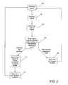
- FIG. 3 is a block diagram illustrating the retail system signal receiver unit of FIGS. 1 and 2 ;
- FIG. 4 is perspective view of the retail system signal receiver unit of FIG. 1 arranged as part of a multi-receiver audible anti-theft alarm system.
- embodiments of the present invention provide a signal receiver unit, shown in the illustrated embodiment as an audible anti-theft alarm receiver unit that, when used in various arrangements of a theft deterrent system, shown in the illustrated embodiment as an audible anti-theft system, may deter theft without discouraging the sale of merchandise.
- FIG. 1 depicts an embodiment of a signal receiver unit, in the illustrated embodiment an retail system signal receiver unit 10 in a first arrangement of a theft deterrent system, in the illustrated embodiment an audible anti-theft system.
- FIG. 1 further illustrates the retail system signal receiver unit 10 relative to other components of the audible anti-theft alarm system, including retail display devices 18 , 21 , and 27 including signal emitting retail devices 20 , 24 , and 28 including sensors and emitters, and an output receiving device such as the computer 36 .
- sensors and emitters are illustrated as contained within signal emitting retail devices 20 , 24 , 28 , it is envisioned that the sensors and emitters may be separate devices in operative communication in manner known in the art and each located in various suitable locations within, on, or around the retail display devices 18 , 21 , 27 as would be understood by one having ordinary skill in the art.
- the retail system receiver unit 10 can be used in many different retail system and anti-theft system arrangements, and the quantity and type of other components, such as retail display devices 18 , 21 , and 27 and signal emitting retail devices 20 , 24 , 28 shown are for illustrative purposes only.
- the signal emitting retail devices 20 , 24 , and 28 may be audible alarm sounding devices or may be various other suitable types of signal emitting retail devices.
- the retail system signal receiver unit 10 may be a audible anti-theft alarm receiver unit or may be a receiver unit for any other suitable type of signal, as described further below.
- the retail system signal receiver unit 10 is adapted to receive and process a signal 32 , in one embodiment a pre-selected audible alarm, emitted by the signal emitting retail devices 20 , 24 , 28 .
- the signal emitting retail devices 20 , 24 , 28 are configured to emit the signal 32 when a potential theft condition occurs.
- the retail system signal receiver unit 10 in one embodiment includes a control circuit, such as in one example a microprocessor that is configured to process the signal 32 and to transmit an output signal 34 to a computer 36 .
- the output signal 34 may be transmitted over a wired connection or wirelessly by any suitable means known in the art. This enables the unit 10 to transmit messages to key store personnel about a possible theft. It is also contemplated that the output signal 34 may be transmitted to PDA's, smart phones, cameras, walkie-talkies, PA systems, and other suitable receiving devices.
- the signal emitting retail devices 20 , 24 , and 28 may be mounted to or otherwise used in conjunction with various retail display devices such as the retail display devices 18 , 21 , and 27 to accommodate the various display needs of retail environments.
- the retail display device 18 includes a sensor and an emitter, illustrated together as contained within a single signal emitting retail device 20 , and also includes a cabinet 22 .
- the cabinet 22 includes a door, such as a transparent sliding door, hinged door, or any other suitable configuration.
- a door In order to remove merchandise, a customer must open the door.
- the sensor of the signal emitting retail device 20 may be configured to sense when the door is opened or when a piece of merchandise is removed from the cabinet.
- the sensor may be a motion sensor, inductive sensor, capacitive sensor, optical sensor, piezo electric sensor, or any other type of sensor known in the art for determining when the door is opened or when a piece of merchandise is removed from the cabinet 22 .
- the emitter of the signal emitting retail device 20 is in operative communication with the sensor and when the sensor detects that the door of the cabinet 22 has been opened or that a piece of merchandise has been removed from the cabinet 22 , the emitter will send out a first signal indicative of the fact that the door of the cabinet 22 has been opened or that a piece of merchandise has been removed from the cabinet 22 .
- the signal emitting retail device 20 may include a timer. When the sensor senses that the door of the cabinet 22 has been opened, the timer of the signal emitting retail device 20 may be started and when the sensor senses that the door of the cabinet 22 has been closed, the timer may be stopped and reset.
- the signal emitting retail device 20 is configured to emit a second signal indicative of the fact that the door has been opened for more than the preset period of time, which may be indicative of a potential theft condition.
- the senor of the signal emitting retail device 20 may sense when a piece of merchandise is removed from the cabinet 22 .
- the signal emitting retail device 20 may also include a control circuit, such as, in one embodiment, a microprocessor, and a memory.
- the control circuit may access the memory to keep track of, for example, the number of times that the door of the cabinet 22 has been opened in a given time period or the number of pieces of merchandise that have been removed from the cabinet 22 in a given time period. If one of these amounts exceeds an adjustable, preset limit, the signal emitting retail device 20 may determine that a potential theft condition exists and is configured to emit a signal indicative of the potential threat condition.
- the retail display device 21 includes a shelving unit 26 upon which merchandise may be displayed.
- the retail display device 21 also includes a sensor and an emitter, illustrated together as contained within a single signal emitting retail device 24 mounted to the shelving unit 26 . It is envisioned that the sensor and emitter of the retail display device 24 may also be housed separately and may be arranged and configured in any suitable configuration.
- the signal emitting retail device 24 may be located in various suitable locations relative to the shelving unit 26 .
- the sensor of the signal emitting retail device 24 is configured to sense when merchandise is removed from the shelving unit 26 .
- the signal emitting retail device 24 is configured to emit a first signal, indicating that merchandise has been removed from the shelving unit 26 , when the sensor determines that merchandise has been removed from the shelving unit 26 .
- the sensor is further configured to determine when a potential theft condition exists, e.g., more than a preset amount of merchandise has been removed in a given period of time, more than a preset number of pieces of merchandise have been removed at once, etc., and to emit a second signal indicating the potential theft condition.
- another retail display device 27 is provided.
- the retail display device 27 includes a hook 30 upon which merchandise may be hung and displayed.
- the retail display device 27 also includes a sensor and an emitter, illustrated together as contained within a single signal emitting retail device 28 mounted proximate the hook 30 . It is envisioned that the sensor and emitter of the retail display device 27 may also be housed separately and may be arranged and configured in any suitable configuration.
- the sensor of the signal emitting retail device 28 is configured to sense when merchandise is removed from the hook 30 .
- the signal emitting retail device 28 is configured to emit a first signal, indicating that merchandise has been removed from the hook 30 when the sensor determines that merchandise has been removed from the hook 30 .
- the sensor is further configured to determine when a potential theft condition exists, e.g., more than a preset amount of merchandise has been removed in a given period of time, more than a preset number of pieces of merchandise have been removed at once, etc., and to emit a second signal indicating the potential theft condition.
- any suitable number of signal emitting retail devices associated with any suitable number of retail display devices may be used with the signal receiver unit 10 . Additionally, in one embodiment, there may be several receiver units provided, each configured to receive signals from one or many signal emitting retail devices.
- the signals emitted by the signal emitting retail devices may be any suitable signal type known in the art, including sound, infrared light, visible light, radio frequency, microwave, combinations thereof, etc.
- Each of the signal emitting retail devices may use the same or different types of signals.
- the signals may have various identifying characteristics that may be identified by the signal receiver unit.
- each signals may include information or distinguishing characteristics regarding the specific signal emitting retail device from which the signal was emitted.
- each signal may include information or distinguishing characteristics indicative of the signal's purpose, e.g., to indicate a piece of merchandise has been removed, to indicate a potential theft condition, etc.
- the signals emitted by the signal emitting retail devices are sound signals.
- the emitters of the signal emitting retail devices are sound emitters, such as, for example, speakers, and are configured to emit sounds that the signal receiver unit will receive and recognize.
- the sounds emitted will have a characteristic that is unique to the signal emitting retail device from which the sound was emitted and that is recognizable by the signal receiver unit. Such characteristics, for example, may include wavelength or frequency of the sound, frequency with which a particular emitter emits sounds, pitch, volume at which the sound is emitted or received, etc. Other characteristics are also envisioned.
- the sounds emitted may include characteristics that are indicative of the event the sounds are intended to indicate, e.g., removal of merchandise, potential theft condition, etc.
- a first signal indicating removal of a piece of merchandise may be sound at a first pitch and volume emitted by a signal emitting retail device and a second signal indicating a potential theft condition may be sound at a second pitch and volume emitted by a signal emitting retail device.
- a second signal indicating a potential theft condition may be sound at a second pitch and volume emitted by a signal emitting retail device.
- the signals emitted by the signal emitting retail devices may include encoded messages using any suitable protocol.
- Information regarding signal emitting retail source device, type of signal, additional information, error information, etc. may be included in the encoded messages. Additionally, many other suitable types of information to be encoded and transmitted by the signal emitting retail devices is also envisioned.
- the receiver unit 10 includes a receiver 12 located on a first face of the main body 11 ; however, one or more receivers 12 may be installed in any acceptable location proximate the main body 11 .
- the receiver 12 may be any suitable type of receiver, e.g., sound receiver, antenna, etc., for receiving signals transmitted by signal transmitting retail devices. Additionally, it is envisioned that that the receiver unit 10 may include multiple receivers each configured to receive different types of signals.
- the receiver unit 10 also includes an output transmitter such as an antenna 16 , although other types of output transmitters such as a wired electrical connection may be used.
- the receiver unit 10 may also include a local indicating device such as a light 14 or any other suitable type of indicating device.
- the light 14 may be used as a local indicator that lights up when the receiver unit 10 receives a signal from a signal transmitting retail device indicating a potential theft condition.
- the receiver unit 10 may alert store personnel to a possible theft in one or more ways, including a local indication that personnel near the receiver unit 10 may see or hear, and a remote indication that is directed to an output device.
- the receiver unit 10 may be configured to monitor for, recognize, and respond to various signals 32 .
- the receiver unit 10 may receive and distinguish signals having a variety of pitches, decibel levels, wavelengths, frequencies, and frequencies of occurrence.
- the receiver unit 10 has the ability to distinguish between a first signal type indicating a normal condition, such as a customer selecting and or removing one of the monitored merchandise and a potential theft condition.
- the receiver unit 10 is configured to transmit an output signal when it has recognized a preset number of signals 32 indicating removal of units of merchandise during a preset period of time, i.e., a preset frequency of occurrence. Such a period of time or frequency of occurrence may be adjustable. Thus, if items of merchandise are being removed from their displays with a regular frequency of occurrence that indicates normal purchasing activity, the receiver unit 10 may be configured not to transmit an output signal 34 . However, if items of merchandise are removed rapidly in a manner that indicates a possible theft condition, for example, the receiver unit 10 will generate an output signal 34 and/or activate the light 14 to alert store personnel.
- the receiver unit 10 is adapted to transmit an output signal 34 in response to receiving the audible signal from a signal transmitting retail device at or exceeding a preset decibel level.
- This preset decibel level may be adjustable.
- the signal transmitting retail device 20 , 24 , or 28 is configured to transmit a softer, lower decibel warning beep if a retail display such as a door of a cabinet 22 is left in an open position for longer than a preset time period, and to increase the volume and decibel level of the warning beep as the amount of time that the retail display remains in the open position increases.
- the receiver unit 10 is configured to transmit an output signal 34 and/or activate the light 14 when the alarm tone received by the receiver unit 10 reaches or exceeds a certain decibel level, thus alerting store personnel to a possible theft or potential theft condition.
- the signal transmitting retail devices can transmit a variety of tones, frequencies, wavelengths, decibel levels, etc. Additionally, a variety of ways to indicate the difference between a normal condition and a theft condition or potential theft condition are envisioned. Additionally, it is envisioned that in some embodiments the signal transmitting retail devices may transmit prerecorded speech messages or signals imitating human speech. Various methods of receiving and processing the various tones, frequencies, wavelengths, frequencies of occurrence, and pitches by the receiver unit 10 are envisioned.
- FIG. 2 a functional schematic of an embodiment of the retail system signal receiver unit 10 is illustrated.
- FIG. 2 shows a first arrangement of the receiver unit 10 relative to other components of an embodiment of a retail anti-theft alarm system, including a first, a second, and an nth signal transmitting retail device 50 , 52 , 54 , an output receiving device 44 , and a power supply 42 .
- the retail system signal receiver unit 10 can be used in many different anti-theft system arrangements, and the components shown in FIG. 2 are for illustrative purposes only.
- the receiver unit 10 includes a receiver 12 , arranged and configured to receive signals 32 from the transmitters 50 , 52 , and 54 (Transmitter n indicating that any potential number of transmitters is envisioned).
- the receiver 12 is in operative communication with a control circuit 38 .
- the control circuit 38 may be a processor, non-programmable or programmable control circuit, integrated circuit, hardwired control circuit, microprocessor of any suitable type, or any suitable type of control circuit.
- the control circuit 38 is in operative communication with a memory storage unit 40 , a local indicating device 56 , and an output transmitter 48 . In one embodiment the control circuit 38 is also in operative communication with a timer unit 41 .
- a power supply 42 provides power to the receiver unit 10 .
- the power supply 42 is shown external to the receiver unit 10 in FIG. 2 , it will be understood that the power supply 42 may be any suitable type of power supply and that power can be supplied to the unit 10 in any suitable way, including an internally connected battery pack. Additionally, one power supply 42 may also supply power to one or more receiver units 10 .
- the power supply 42 of the receiver unit 10 is an internally connected battery pack, and the output transmitter 48 is wireless transmitter such as an antenna.
- the receiver unit 10 is wireless, and may be installed in many convenient locations in a retail environment without requiring significant installation time or shelving space down time.
- the output receiving device 44 is shown in FIG. 1 as a computer 36 , but any suitable output receiving device 44 may be used, including a cellular phone, pager, camera, public address (PA) system, etc.
- a system is set up in a retail environment.
- various signal emitting retail devices cooperatively arranged throughout the store with retail display devices, emit signals.
- the receiver of a signal receiver unit waits to receive a signal 60 .
- the control circuit of the signal receiver unit then recognizes the reception of a signal and begins processing the signal 62 .
- the control circuit determines the origin of the signal 64 , i.e., the retail display device and signal emitting retail device from which the signal was sent.
- the control circuit determines whether the signal indicates a merchandise dispensing event, e.g., a person removing an item of merchandise from a shelf or cabinet of a retail display device, opening the door of a retail display device, removing a piece of merchandise from a hook, etc., or whether the signal indicates a potential theft condition, e.g., the door of a retail display device being left open for a period of time more than a preset period of time, the door being opened more than a preset number of times within a preset period of time, more than a preset number of pieces of merchandise being removed from a retail display device during a preset period of time, etc. 66 .
- a merchandise dispensing event e.g., a person removing an item of merchandise from a shelf or cabinet of a retail display device, opening the door of a retail display device, removing a piece of merchandise from a hook, etc.
- a potential theft condition e.g., the door of a retail display device being left
- the control circuit stores, e.g., in local or remote memory, the time that the retail dispensing event took place and the location, i.e., the retail display device, at which the retail dispensing event took place 68 . If the signal is determined to indicate a potential theft condition, the control circuit sends an output signal indicative of a potential theft condition via the output transmitter to an output device 70 , with the output signal including information regarding the location, i.e., the retail display device, at which the potential theft condition took place. For example, in one embodiment an output device is a camera, and the output signal triggers the camera to record an image or video of the location of the potential theft condition. The control circuit then causes to be stored, e.g., in local or remote memory, the time and location at which the potential theft condition took place 72 .
- the receiver unit 10 can be queried to output a report of stored merchandise dispensing events and/or potential theft.
- the reports may be configured to be received and read by an external software program on an external hardware device.
- Such reports may be correlated with the merchandise that is displayed at various retail display devices to determine, e.g., selling rates at different times, times of potential theft conditions, and various other useful information. Additionally, for example, times included in the reports may be crosschecked against video data recorded by other retail security systems to help identify those who triggered potential theft conditions.
- FIG. 4 one embodiment of a first receiver unit 110 is shown relaying the signal 32 to a second receiver unit 210 via a relaying signal 46 .
- the second receiver unit 210 may activate its local indicator device 214 , allowing store employees close to the second receiver unit 210 to be notified of a possible theft in an area close to the first receiver unit 110 .
- This setup is exemplary, and it is envisioned that in some embodiments any number of receiver units may relay signals in the manner described above to, for example, notify employees throughout the store of a potential theft condition. Additionally, it is also envisioned that the signals passed between receiver units may include information allowing the receiver unit to display or in any manner known in the art communicate to store employees the location of a potential theft condition.
- the receiver 12 receives ambient noise from the surrounding area.
- the processor 38 monitors the ambient noise received by the receiver 12 , and is configured to recognize one or more signals 32 , in this embodiment preset audible alarm signals within the ambient noise.
- the processor 38 is configured to signal the output transmitter 48 to generate an output signal 34 .
- the output receiving device 44 receives the output signal 34 .
- the processor 38 also activates the local indicator device 56 upon recognition of a preset pitch, frequency of occurrence, frequency, wavelength, or decibel level of an audible alarm signal 32 .
- the processor 38 is also configured to store information, determined by the processor based on the recognized audible alarm signal 32 , in the memory storage unit 40 .
- the processor 38 periodically accesses the memory storage unit 40 and compiles a report of collected data over a certain period of time. The generated report is then transmitted through the output transmitter 16 or other suitable means to an output device 36 .
Abstract
Description
Claims (6)
Priority Applications (2)
| Application Number | Priority Date | Filing Date | Title |
|---|---|---|---|
| US13/312,644 US8803687B2 (en) | 2011-12-06 | 2011-12-06 | Retail system signal receiver unit for recognizing a preset audible alarm tone |
| PCT/US2012/068099 WO2013086088A1 (en) | 2011-12-06 | 2012-12-06 | Retail system signal receiver unit |
Applications Claiming Priority (1)
| Application Number | Priority Date | Filing Date | Title |
|---|---|---|---|
| US13/312,644 US8803687B2 (en) | 2011-12-06 | 2011-12-06 | Retail system signal receiver unit for recognizing a preset audible alarm tone |
Publications (2)
| Publication Number | Publication Date |
|---|---|
| US20130142494A1 US20130142494A1 (en) | 2013-06-06 |
| US8803687B2 true US8803687B2 (en) | 2014-08-12 |
Family
ID=48524080
Family Applications (1)
| Application Number | Title | Priority Date | Filing Date |
|---|---|---|---|
| US13/312,644 Active 2032-09-18 US8803687B2 (en) | 2011-12-06 | 2011-12-06 | Retail system signal receiver unit for recognizing a preset audible alarm tone |
Country Status (2)
| Country | Link |
|---|---|
| US (1) | US8803687B2 (en) |
| WO (1) | WO2013086088A1 (en) |
Cited By (14)
| Publication number | Priority date | Publication date | Assignee | Title |
|---|---|---|---|---|
| WO2014084961A1 (en) | 2012-10-08 | 2014-06-05 | Devicor Medical Products, Inc. | Tissue biopsy device with thumbwheel and sample holder |
| US20140163976A1 (en) * | 2012-12-10 | 2014-06-12 | Samsung Electronics Co., Ltd. | Method and user device for providing context awareness service using speech recognition |
| US20140210621A1 (en) * | 2013-01-31 | 2014-07-31 | Wal-Mart Stores, Inc. | Theft detection system |
| US10121341B2 (en) | 2017-01-23 | 2018-11-06 | Southern Imperial Llc | Retail merchandise hook with radio transmission |
| US10186124B1 (en) | 2017-10-26 | 2019-01-22 | Scott Charles Mullins | Behavioral intrusion detection system |
| EP3543980A1 (en) | 2018-03-21 | 2019-09-25 | Fasteners for Retail, Inc. | Anti-theft device with remote alarm feature |
| US10993550B2 (en) | 2018-03-21 | 2021-05-04 | Fasteners For Retail, Inc. | Anti-theft retail merchandise pusher with remote alarm feature |
| US11094327B2 (en) * | 2018-09-28 | 2021-08-17 | Lenovo (Singapore) Pte. Ltd. | Audible input transcription |
| US11205330B2 (en) * | 2018-11-30 | 2021-12-21 | Indyme Solutions, Llc | Anti-theft response randomizer |
| US11363894B2 (en) | 2019-04-05 | 2022-06-21 | Fasteners For Retail, Inc. | Anti-theft pusher with incremental distance detection |
| US11397914B2 (en) | 2004-02-03 | 2022-07-26 | Rtc Industries, Inc. | Continuous display shelf edge label device |
| US11468401B2 (en) | 2014-11-12 | 2022-10-11 | Rtc Industries, Inc. | Application system for inventory management |
| US11580812B2 (en) | 2004-02-03 | 2023-02-14 | Rtc Industries, Inc. | System for inventory management |
| US11961319B2 (en) | 2019-04-10 | 2024-04-16 | Raptor Vision, Llc | Monitoring systems |
Families Citing this family (10)
| Publication number | Priority date | Publication date | Assignee | Title |
|---|---|---|---|---|
| US8629772B2 (en) | 2011-12-06 | 2014-01-14 | Southern Imperial, Inc. | Signal emitting retail device |
| US9318008B2 (en) | 2011-12-06 | 2016-04-19 | Southern Imperial, Inc. | Signal emitting retail device |
| US8884761B2 (en) | 2012-08-21 | 2014-11-11 | Souther Imperial, Inc. | Theft detection device and method for controlling |
| US9324220B2 (en) | 2012-08-21 | 2016-04-26 | Southern Imperial, Inc. | Theft detection device and method for controlling same |
| CN105225407A (en) * | 2015-10-20 | 2016-01-06 | 张浩杰 | A kind of home security electronic monitoring and control system |
| US9779603B1 (en) * | 2016-06-28 | 2017-10-03 | Walgreen Co. | Remote trigger for security system |
| JP6981463B2 (en) * | 2017-03-06 | 2021-12-15 | 日本電気株式会社 | Product monitoring device, product monitoring system, output destination device, product monitoring method, display method and program |
| US10452924B2 (en) * | 2018-01-10 | 2019-10-22 | Trax Technology Solutions Pte Ltd. | Withholding alerts due to temporary shelf occlusion |
| US11087601B1 (en) | 2020-04-02 | 2021-08-10 | Fasteners For Retail, Inc | Anti-theft device with cable attachment |
| USD956607S1 (en) | 2020-04-16 | 2022-07-05 | Fasteners For Retail, Inc. | Security tag holder |
Citations (16)
| Publication number | Priority date | Publication date | Assignee | Title |
|---|---|---|---|---|
| WO2001081988A2 (en) | 2000-04-26 | 2001-11-01 | British Technology Group Intercorporate Licensing Limited | Variable optical filter and devices applying such filter |
| US20020067259A1 (en) * | 2000-09-29 | 2002-06-06 | Fufidio Michael Vincent | Portal intrusion detection apparatus and method |
| US20030175004A1 (en) | 2002-02-19 | 2003-09-18 | Garito Anthony F. | Optical polymer nanocomposites |
| US20030227382A1 (en) * | 2002-06-11 | 2003-12-11 | Breed David S. | Low power remote asset monitoring |
| US6690411B2 (en) * | 1999-07-20 | 2004-02-10 | @Security Broadband Corp. | Security system |
| US20060198611A1 (en) * | 2005-03-03 | 2006-09-07 | Jung-Jae Park | Digital video recording method in an audio detection mode |
| KR100823026B1 (en) | 2006-11-30 | 2008-04-17 | 백홍주 | An alarm apparatus for robbery protection of portable |
| US20090109027A1 (en) | 2007-10-26 | 2009-04-30 | Carmen Schuller | Anti-thief device |
| US20100175438A1 (en) | 2009-01-13 | 2010-07-15 | Invue Security Products Inc. | Combination non-programmable and programmable key for security device |
| KR20100137956A (en) | 2009-06-24 | 2010-12-31 | 엘지이노텍 주식회사 | Apparatus and method for alarming burglar of electronic shelf label |
| WO2011025085A1 (en) | 2009-08-25 | 2011-03-03 | Axium Technologies, Inc. | Method and system for combined audio-visual surveillance cross-reference to related applications |
| KR20110002261U (en) | 2009-08-28 | 2011-03-08 | 황연지 | Vending machine |
| KR20110043837A (en) | 2009-10-22 | 2011-04-28 | 권경채 | Steal preventing system |
| KR20110080411A (en) | 2010-01-05 | 2011-07-13 | 전복집 | An apparatus for preventing steal |
| US20110215060A1 (en) | 2010-03-04 | 2011-09-08 | Southern Imperial, Inc. | Alarm Sounding Retail Display System |
| US20110227735A1 (en) | 2010-03-16 | 2011-09-22 | Invue Security Products Inc. | Merchandise display security system including magnetic sensor |
-
2011
- 2011-12-06 US US13/312,644 patent/US8803687B2/en active Active
-
2012
- 2012-12-06 WO PCT/US2012/068099 patent/WO2013086088A1/en active Application Filing
Patent Citations (16)
| Publication number | Priority date | Publication date | Assignee | Title |
|---|---|---|---|---|
| US6690411B2 (en) * | 1999-07-20 | 2004-02-10 | @Security Broadband Corp. | Security system |
| WO2001081988A2 (en) | 2000-04-26 | 2001-11-01 | British Technology Group Intercorporate Licensing Limited | Variable optical filter and devices applying such filter |
| US20020067259A1 (en) * | 2000-09-29 | 2002-06-06 | Fufidio Michael Vincent | Portal intrusion detection apparatus and method |
| US20030175004A1 (en) | 2002-02-19 | 2003-09-18 | Garito Anthony F. | Optical polymer nanocomposites |
| US20030227382A1 (en) * | 2002-06-11 | 2003-12-11 | Breed David S. | Low power remote asset monitoring |
| US20060198611A1 (en) * | 2005-03-03 | 2006-09-07 | Jung-Jae Park | Digital video recording method in an audio detection mode |
| KR100823026B1 (en) | 2006-11-30 | 2008-04-17 | 백홍주 | An alarm apparatus for robbery protection of portable |
| US20090109027A1 (en) | 2007-10-26 | 2009-04-30 | Carmen Schuller | Anti-thief device |
| US20100175438A1 (en) | 2009-01-13 | 2010-07-15 | Invue Security Products Inc. | Combination non-programmable and programmable key for security device |
| KR20100137956A (en) | 2009-06-24 | 2010-12-31 | 엘지이노텍 주식회사 | Apparatus and method for alarming burglar of electronic shelf label |
| WO2011025085A1 (en) | 2009-08-25 | 2011-03-03 | Axium Technologies, Inc. | Method and system for combined audio-visual surveillance cross-reference to related applications |
| KR20110002261U (en) | 2009-08-28 | 2011-03-08 | 황연지 | Vending machine |
| KR20110043837A (en) | 2009-10-22 | 2011-04-28 | 권경채 | Steal preventing system |
| KR20110080411A (en) | 2010-01-05 | 2011-07-13 | 전복집 | An apparatus for preventing steal |
| US20110215060A1 (en) | 2010-03-04 | 2011-09-08 | Southern Imperial, Inc. | Alarm Sounding Retail Display System |
| US20110227735A1 (en) | 2010-03-16 | 2011-09-22 | Invue Security Products Inc. | Merchandise display security system including magnetic sensor |
Non-Patent Citations (2)
| Title |
|---|
| Indyme smartresponse; 2 pages printed from internet http://www.indyme.com/; date last visited Apr. 8, 2013. |
| U.S. Appl. No. 13/312,699, filed Dec. 6, 2011, Valiulis et al. |
Cited By (36)
| Publication number | Priority date | Publication date | Assignee | Title |
|---|---|---|---|---|
| US11580812B2 (en) | 2004-02-03 | 2023-02-14 | Rtc Industries, Inc. | System for inventory management |
| US11397914B2 (en) | 2004-02-03 | 2022-07-26 | Rtc Industries, Inc. | Continuous display shelf edge label device |
| WO2014084961A1 (en) | 2012-10-08 | 2014-06-05 | Devicor Medical Products, Inc. | Tissue biopsy device with thumbwheel and sample holder |
| US11410640B2 (en) * | 2012-12-10 | 2022-08-09 | Samsung Electronics Co., Ltd. | Method and user device for providing context awareness service using speech recognition |
| US9940924B2 (en) * | 2012-12-10 | 2018-04-10 | Samsung Electronics Co., Ltd. | Method and user device for providing context awareness service using speech recognition |
| US20180182374A1 (en) * | 2012-12-10 | 2018-06-28 | Samsung Electronics Co., Ltd. | Method and user device for providing context awareness service using speech recognition |
| US10395639B2 (en) * | 2012-12-10 | 2019-08-27 | Samsung Electronics Co., Ltd. | Method and user device for providing context awareness service using speech recognition |
| US20140163976A1 (en) * | 2012-12-10 | 2014-06-12 | Samsung Electronics Co., Ltd. | Method and user device for providing context awareness service using speech recognition |
| US20190362705A1 (en) * | 2012-12-10 | 2019-11-28 | Samsung Electronics Co., Ltd. | Method and user device for providing context awareness service using speech recognition |
| US20220383852A1 (en) * | 2012-12-10 | 2022-12-01 | Samsung Electronics Co., Ltd. | Method and user device for providing context awareness service using speech recognition |
| US10832655B2 (en) * | 2012-12-10 | 2020-11-10 | Samsung Electronics Co., Ltd. | Method and user device for providing context awareness service using speech recognition |
| US11721320B2 (en) * | 2012-12-10 | 2023-08-08 | Samsung Electronics Co., Ltd. | Method and user device for providing context awareness service using speech recognition |
| US9035771B2 (en) * | 2013-01-31 | 2015-05-19 | Wal-Mart Stores, Inc. | Theft detection system |
| US20140210621A1 (en) * | 2013-01-31 | 2014-07-31 | Wal-Mart Stores, Inc. | Theft detection system |
| US11468401B2 (en) | 2014-11-12 | 2022-10-11 | Rtc Industries, Inc. | Application system for inventory management |
| US10121341B2 (en) | 2017-01-23 | 2018-11-06 | Southern Imperial Llc | Retail merchandise hook with radio transmission |
| US11663893B2 (en) | 2017-01-23 | 2023-05-30 | Fasteners For Retail, Inc. | Anti-theft retail merchandise hook with radio transmission |
| US10997839B2 (en) | 2017-01-23 | 2021-05-04 | Fasteners For Retail, Inc. | Retail merchandise hook with radio transmission |
| US11295591B2 (en) | 2017-01-23 | 2022-04-05 | Fasteners For Retail, Inc. | Anti-theft retail merchandise hook with radio transmission |
| US10720035B2 (en) | 2017-01-23 | 2020-07-21 | Fasteners For Retail, Inc. | Anti-theft retail merchandise hook with radio transmission |
| US11682277B2 (en) | 2017-10-26 | 2023-06-20 | Raptor Vision, Llc | Video analytics system |
| US11328566B2 (en) | 2017-10-26 | 2022-05-10 | Scott Charles Mullins | Video analytics system |
| US10497231B2 (en) | 2017-10-26 | 2019-12-03 | Scott Charles Mullins | Behavioral intrusion detection system |
| US10186124B1 (en) | 2017-10-26 | 2019-01-22 | Scott Charles Mullins | Behavioral intrusion detection system |
| EP3543980A1 (en) | 2018-03-21 | 2019-09-25 | Fasteners for Retail, Inc. | Anti-theft device with remote alarm feature |
| US11317738B2 (en) | 2018-03-21 | 2022-05-03 | Fasteners For Retail, Inc. | Anti-theft retail merchandise pusher with remote alarm feature |
| US11605276B2 (en) | 2018-03-21 | 2023-03-14 | Fasteners For Retail, Inc. | Anti-theft device with remote alarm feature |
| US10993550B2 (en) | 2018-03-21 | 2021-05-04 | Fasteners For Retail, Inc. | Anti-theft retail merchandise pusher with remote alarm feature |
| US10885753B2 (en) | 2018-03-21 | 2021-01-05 | Fasteners For Retail, Inc. | Anti-theft device with remote alarm feature |
| US11737579B2 (en) | 2018-03-21 | 2023-08-29 | Fasteners For Retail, Inc. | Anti-theft retail merchandise pusher with remote alarm feature |
| EP4254375A2 (en) | 2018-03-21 | 2023-10-04 | Fasteners for Retail, Inc. | Anti-theft device with remote alarm feature |
| US11094327B2 (en) * | 2018-09-28 | 2021-08-17 | Lenovo (Singapore) Pte. Ltd. | Audible input transcription |
| US11205330B2 (en) * | 2018-11-30 | 2021-12-21 | Indyme Solutions, Llc | Anti-theft response randomizer |
| US11363894B2 (en) | 2019-04-05 | 2022-06-21 | Fasteners For Retail, Inc. | Anti-theft pusher with incremental distance detection |
| US11707141B2 (en) | 2019-04-05 | 2023-07-25 | Fasteners For Retail, Inc. | Anti-theft pusher with incremental distance detection |
| US11961319B2 (en) | 2019-04-10 | 2024-04-16 | Raptor Vision, Llc | Monitoring systems |
Also Published As
| Publication number | Publication date |
|---|---|
| WO2013086088A1 (en) | 2013-06-13 |
| US20130142494A1 (en) | 2013-06-06 |
Similar Documents
| Publication | Publication Date | Title |
|---|---|---|
| US8803687B2 (en) | Retail system signal receiver unit for recognizing a preset audible alarm tone | |
| US11663893B2 (en) | Anti-theft retail merchandise hook with radio transmission | |
| US9318007B2 (en) | Signal emitting retail device | |
| JP6473986B2 (en) | Commodity movement sensor system and method of use thereof | |
| US9318008B2 (en) | Signal emitting retail device | |
| US8106772B2 (en) | Tether cord and sensor alarms | |
| US11605276B2 (en) | Anti-theft device with remote alarm feature | |
| JP2009505253A (en) | Method and apparatus for protecting objects | |
| GB2496196A (en) | Fire and theft detection system implemented via a games console | |
| WO2014047272A1 (en) | Merchandise security device including motion sensor for activating audio indicator | |
| KR101686800B1 (en) | System for Collecting Shopping Information using Theft Preventive Tag and Method thereof | |
| CA2348535C (en) | Security systems for inhibiting theft of goods from retail stores | |
| WO2015142729A1 (en) | Signal emitting retail device | |
| ZA200103357B (en) | Security systems for inhibiting theft of goods from retail stores. | |
| JPS63303497A (en) | Burglar preventing device |
Legal Events
| Date | Code | Title | Description |
|---|---|---|---|
| AS | Assignment |
Owner name: SOUTHERN IMPERIAL, INC., ILLINOIS Free format text: ASSIGNMENT OF ASSIGNORS INTEREST;ASSIGNORS:VALIULIS, THOMAS E.;VALIULIS, PETER T.;REEL/FRAME:027344/0502 Effective date: 20111123 |
|
| STCF | Information on status: patent grant |
Free format text: PATENTED CASE |
|
| AS | Assignment |
Owner name: JPMORGAN CHASE BANK, N.A., ILLINOIS Free format text: SECURITY INTEREST;ASSIGNOR:SOUTHERN IMPERIAL, INC.;REEL/FRAME:036089/0804 Effective date: 20150706 |
|
| AS | Assignment |
Owner name: ANTARES CAPITAL LP, AS AGENT, ILLINOIS Free format text: SECURITY INTEREST;ASSIGNOR:SOUTHERN IMPERIAL LLC;REEL/FRAME:043431/0639 Effective date: 20170803 |
|
| AS | Assignment |
Owner name: SOUTHERN IMPERIAL, INC., ILLINOIS Free format text: RELEASE BY SECURED PARTY;ASSIGNOR:JPMORGAN CHASE BANK, N.A.;REEL/FRAME:043971/0505 Effective date: 20170803 |
|
| AS | Assignment |
Owner name: SOUTHERN IMPERIAL LLC, ILLINOIS Free format text: ASSIGNMENT OF ASSIGNORS INTEREST;ASSIGNOR:SOUTHERN IMPERIAL, INC.;REEL/FRAME:043925/0049 Effective date: 20170802 |
|
| MAFP | Maintenance fee payment |
Free format text: PAYMENT OF MAINTENANCE FEE, 4TH YR, SMALL ENTITY (ORIGINAL EVENT CODE: M2551) Year of fee payment: 4 |
|
| FEPP | Fee payment procedure |
Free format text: ENTITY STATUS SET TO UNDISCOUNTED (ORIGINAL EVENT CODE: BIG.) |
|
| FEPP | Fee payment procedure |
Free format text: PETITION RELATED TO MAINTENANCE FEES GRANTED (ORIGINAL EVENT CODE: PTGR); ENTITY STATUS OF PATENT OWNER: LARGE ENTITY |
|
| MAFP | Maintenance fee payment |
Free format text: PAYMENT OF MAINTENANCE FEE UNDER 1.28(C) (ORIGINAL EVENT CODE: M1559); ENTITY STATUS OF PATENT OWNER: LARGE ENTITY |
|
| AS | Assignment |
Owner name: FASTENERS FOR RETAIL, INC., OHIO Free format text: MERGER;ASSIGNOR:SOUTHERN IMPERIAL LLC;REEL/FRAME:049056/0321 Effective date: 20181206 |
|
| MAFP | Maintenance fee payment |
Free format text: PAYMENT OF MAINTENANCE FEE, 8TH YEAR, LARGE ENTITY (ORIGINAL EVENT CODE: M1552); ENTITY STATUS OF PATENT OWNER: LARGE ENTITY Year of fee payment: 8 |
|
| AS | Assignment |
Owner name: CERBERUS BUSINESS FINANCE AGENCY, LLC, NEW YORK Free format text: SECURITY INTEREST;ASSIGNOR:FASTENERS FOR RETAIL, INC.;REEL/FRAME:061365/0643 Effective date: 20220901 Owner name: SOUTHERN IMPERIAL LLC, ILLINOIS Free format text: RELEASE BY SECURED PARTY;ASSIGNOR:ANTARES CAPITAL LP;REEL/FRAME:061370/0311 Effective date: 20220901 |