US8770779B2 - Small aperture recessed wall wash downlight - Google Patents

Small aperture recessed wall wash downlight Download PDF

Info

Publication number
US8770779B2
US8770779B2 US13/537,466 US201213537466A US8770779B2 US 8770779 B2 US8770779 B2 US 8770779B2 US 201213537466 A US201213537466 A US 201213537466A US 8770779 B2 US8770779 B2 US 8770779B2
Authority
US
United States
Prior art keywords
lighting fixture
light
wall
wall wash
light pipe
Prior art date
Legal status (The legal status is an assumption and is not a legal conclusion. Google has not performed a legal analysis and makes no representation as to the accuracy of the status listed.)
Active, expires
Application number
US13/537,466
Other versions
US20140003039A1 (en
Inventor
Connie A. Steadman
Shawn A. Wilcox
Current Assignee (The listed assignees may be inaccurate. Google has not performed a legal analysis and makes no representation or warranty as to the accuracy of the list.)
Ally Bank As Collateral Agent
Atlantic Park Strategic Capital Fund LP Collateral Agent AS
Original Assignee
Hubbell Inc
Priority date (The priority date is an assumption and is not a legal conclusion. Google has not performed a legal analysis and makes no representation as to the accuracy of the date listed.)
Filing date
Publication date
Application filed by Hubbell Inc filed Critical Hubbell Inc
Priority to US13/537,466 priority Critical patent/US8770779B2/en
Assigned to HUBBELL INCORPORATED reassignment HUBBELL INCORPORATED ASSIGNMENT OF ASSIGNORS INTEREST (SEE DOCUMENT FOR DETAILS). Assignors: STEADMAN, CONNIE, WILCOX, SHAWN
Publication of US20140003039A1 publication Critical patent/US20140003039A1/en
Application granted granted Critical
Publication of US8770779B2 publication Critical patent/US8770779B2/en
Assigned to HUBBELL LIGHTING, INC. reassignment HUBBELL LIGHTING, INC. NUNC PRO TUNC ASSIGNMENT (SEE DOCUMENT FOR DETAILS). Assignors: HUBBELL INCORPORATED
Assigned to ALLY BANK, AS COLLATERAL AGENT reassignment ALLY BANK, AS COLLATERAL AGENT SECURITY AGREEMENT Assignors: CURRENT LIGHTING SOLUTIONS, LLC, DAINTREE NEETWORKS INC., FORUM, INC., HUBBELL LIGHTING, INC., LITECONTROL CORPORATION
Assigned to ATLANTIC PARK STRATEGIC CAPITAL FUND, L.P., AS COLLATERAL AGENT reassignment ATLANTIC PARK STRATEGIC CAPITAL FUND, L.P., AS COLLATERAL AGENT SECURITY INTEREST (SEE DOCUMENT FOR DETAILS). Assignors: CURRENT LIGHTING SOLUTIONS, LLC, DAINTREE NETWORKS INC., FORUM, INC., HUBBELL LIGHTING, INC., LITECONTROL CORPORATION
Assigned to ALLY BANK, AS COLLATERAL AGENT reassignment ALLY BANK, AS COLLATERAL AGENT CORRECTIVE ASSIGNMENT TO CORRECT THE PATENT NUMBER 10841994 TO PATENT NUMBER 11570872 PREVIOUSLY RECORDED ON REEL 058982 FRAME 0844. ASSIGNOR(S) HEREBY CONFIRMS THE SECURITY AGREEMENT. Assignors: CURRENT LIGHTING SOLUTIONS, LLC, DAINTREE NETWORKS INC., FORUM, INC., HUBBELL LIGHTING, INC., LITECONTROL CORPORATION
Assigned to ATLANTIC PARK STRATEGIC CAPITAL FUND, L.P., AS COLLATERAL AGENT reassignment ATLANTIC PARK STRATEGIC CAPITAL FUND, L.P., AS COLLATERAL AGENT CORRECTIVE ASSIGNMENT TO CORRECT THE PATENT NUMBER PREVIOUSLY RECORDED AT REEL: 059034 FRAME: 0469. ASSIGNOR(S) HEREBY CONFIRMS THE SECURITY INTEREST. Assignors: CURRENT LIGHTING SOLUTIONS, LLC, DAINTREE NETWORKS INC., FORUM, INC., HUBBELL LIGHTING, INC., LITECONTROL CORPORATION
Active legal-status Critical Current
Adjusted expiration legal-status Critical

Links

Images

Classifications

    • FMECHANICAL ENGINEERING; LIGHTING; HEATING; WEAPONS; BLASTING
    • F21LIGHTING
    • F21SNON-PORTABLE LIGHTING DEVICES; SYSTEMS THEREOF; VEHICLE LIGHTING DEVICES SPECIALLY ADAPTED FOR VEHICLE EXTERIORS
    • F21S8/00Lighting devices intended for fixed installation
    • F21S8/02Lighting devices intended for fixed installation of recess-mounted type, e.g. downlighters
    • F21S8/022Lighting devices intended for fixed installation of recess-mounted type, e.g. downlighters intended to be recessed in a floor or like ground surface, e.g. pavement or false floor
    • FMECHANICAL ENGINEERING; LIGHTING; HEATING; WEAPONS; BLASTING
    • F21LIGHTING
    • F21VFUNCTIONAL FEATURES OR DETAILS OF LIGHTING DEVICES OR SYSTEMS THEREOF; STRUCTURAL COMBINATIONS OF LIGHTING DEVICES WITH OTHER ARTICLES, NOT OTHERWISE PROVIDED FOR
    • F21V21/00Supporting, suspending, or attaching arrangements for lighting devices; Hand grips
    • F21V21/02Wall, ceiling, or floor bases; Fixing pendants or arms to the bases
    • F21V21/04Recessed bases
    • GPHYSICS
    • G02OPTICS
    • G02BOPTICAL ELEMENTS, SYSTEMS OR APPARATUS
    • G02B6/00Light guides; Structural details of arrangements comprising light guides and other optical elements, e.g. couplings
    • G02B6/02Optical fibres with cladding with or without a coating

Abstract

A wall wash lighting fixture includes a light source, a light pipe below the light source and a reflector offset from and surrounding the lower end of the light pipe. The lower end of the light pipe has an oblique, light-emitting face that provides uniform wall illumination up to a high vertical angle. The reflector faces substantially away from the wall and provides room-side illumination below about 45 vertical degrees. A preferred embodiment is suited for retrofit recessed installation, especially where small-aperture downlights are desired.

Description

FIELD OF THE INVENTION
The invention relates to lighting fixtures, in particular, to “wall wash” downlights adapted primarily to illuminate a nearby wall.
BACKGROUND OF THE INVENTION
Wall wash downlights typically are recessed in a ceiling near a wall to be illuminated and usually illuminate nearby areas of the room in which they are installed. Many traditional wall wash downlight designs rely on tilting the light source toward the wall and/or employ a “kicker” within the lower portion of the reflector (see, e.g., U.S. Pat. No. 7,125,135 to Ward). Others combine reflectors with broad lenses (see, e.g., U.S. Pat. No. 6,994,456 to Russo, et al). These traditional approaches usually are not workable in the cramped interiors of increasingly popular small aperture (about 2¼ in. diameter) downlights, which often are designed to be installed and/or accessible from below the ceiling.
SUMMARY OF THE INVENTION
The lighting fixture of the invention is a compactly configured wall wash arrangement that maximizes wall illuminance (particularly at high vertical angles) and wall illumination uniformity and minimizes room-side glare, making it well suited for applications that specify small aperture downlights.
One aspect of the invention concerns a wall wash lighting fixture for installation near a wall, the fixture comprising a light source, a light pipe below the light source and a reflector at least partially surrounding the lower end of the light pipe. The light pipe comprises a light-receiving upper end adjacent the light source and a lower end having a slanted, light-emitting face, which obliquely faces the wall with its high point closer to the wall than its low point. The reflector faces substantially away from the wall to redirect a portion of the light emitted by the slanted face of the light pipe away from the wall, toward the room side of the fixture.
The reflector preferably is configured and positioned such that substantially all of the light it redirects toward the room side emerges from the fixture below about 45° from the vertical. The light pipe preferably has the form of a circular cylinder, the slanted light-emitting face being oval in shape and having light-refracting elements that comprise a lenticular array of 90° prisms. Preferably, an internally reflective shield surrounds the light pipe to direct inwardly any light that may escape from the light pipe before reaching its slanted face.
Another aspect of the invention concerns the juxtaposition of parts that comprise a wall wash lighting fixture of the aforementioned type, which also comprises a housing in which the light source, the light pipe and the reflector are situated. The housing has a central longitudinal housing axis; the light source has a central longitudinal light source axis; the light pipe has a central longitudinal light pipe axis; and the reflector has a central longitudinal reflector axis. All four of the axes are substantially parallel; the housing axis and the reflector axis are substantially coaxial; and the light source axis and the light pipe axis are substantially coaxial and offset from the housing axis and the reflector axis.
BRIEF DESCRIPTION OF THE DRAWING
A preferred embodiment of the disclosed invention, including the best mode for carrying out the invention, is described in detail below, purely by way of example, with reference to the accompanying drawing, in which:
FIG. 1 is a side elevational view of the wall wash lighting fixture of the invention installed with a power supply above a ceiling;
FIG. 2 is a bottom perspective view of the wall wash lighting fixture per se of FIG. 1;
FIG. 3 is an exploded perspective view of the wall wash lighting fixture of FIG. 1;
FIG. 4 is an exploded perspective view of the light pipe and shield components of the wall wash lighting fixture of FIG. 1, as delineated by line 4-4 in FIG. 3;
FIG. 5 is a perspective view of the wall wash lighting fixture of FIG. 1, the fixture shown without its housing to reveal otherwise hidden details;
FIG. 6 is a bottom plan view thereof;
FIG. 7 is a partial side elevational view thereof;
FIG. 8 is a bottom perspective view of a spacer component of the wall wash lighting fixture of FIG. 1;
FIG. 9 is a top perspective view thereof;
FIG. 10 is a side elevational view of the light pipe component of the wall wash lighting fixture of FIG. 1;
FIG. 11 is a detail view thereof, taken along line 11-11 in FIG. 10;
FIG. 12 is a partial bottom perspective view thereof;
FIG. 13 is a schematic ray trace diagram of the wall wash lighting fixture of FIG. 1, based on a longitudinal sectional view through the reflector and the shield components (but not through the light pipe);
FIG. 14 consists of a candela distribution graph and a table of intensity as a function of angle of the wall wash lighting fixture of FIG. 1;
FIG. 15 is a table of luminance as a function of angle thereof; and
FIG. 16 is a table of wall illuminance distribution thereof in footcandles.
DETAILED DESCRIPTION OF THE INVENTION
Referring to FIGS. 1-3, a wall wash lighting fixture 2 according to the invention is designed to be installed in and above a ceiling C near a wall W to be illuminated. A supply box S feeds electrical power to the fixture via wiring in a flexible metal conduit M coupled to a junction box 4. In a preferred embodiment, supply box S houses a step-down transformer or electronic LED driver/power supply (not shown) and supports a thermal protector T. Three screws 6 attach junction box 4 to the top of the fixture's finned aluminum heat sink 8. Two screws 9 secure the cover of junction box 4 in place. Junction box 4 and supply box S preferably are mechanically connected by a flexible metallic tether (not shown) that runs through conduit M and functions as a strain relief as well as a grounding cable. Such a tether and suitable alternatives are disclosed in commonly owned U.S. patent application Ser. No. 13/466,533, filed May 8, 2012, which is incorporated herein in its entirety.
A tubular aluminum housing 10 below heat sink 8 is coaxial with the heat sink and with a preferably aluminum reflector 12, which has an offset cutout 13 and an exposed bottom annular trim flange 14. Reflector 12 is bonded to housing 10, preferably by silicone adhesive. Heat sink 8 and housing 10 are rigidly interconnected by a spacer 15, which is described in detail below. Two flat, oppositely directed retention springs 16 are secured tangentially to housing 10 by screws 18. Retention springs 16 removably secure housing 10 (and hence the entire fixture) in a properly sized installation hole H in ceiling C, with trim flange 14 bearing against the lower surface of the ceiling.
Installation of the lighting fixture is straightforward. Supply wiring above the ceiling is pulled through the fixture installation hole H and connected to the fixture wiring in supply box S, which is then passed upward through the installation hole H followed by flexible conduit M. Supply box S simply rests on the upper surface of the ceiling. With retention springs 16 manually squeezed around housing 10, the fixture is pushed upward into the installation hole until the springs pop out above the ceiling, locking the fixture in place. A slight clockwise twist of the reflector trim flange 14 seats it firmly against the ceiling. The fixture can be removed from the ceiling easily by first twisting the trim flange 14 slightly counterclockwise while applying slight downward pressure. Once the retention springs 16 are accessible, they are squeezed together and the housing 10 is pulled down out of the installation hole, followed by flexible conduit M and supply box S. While described herein as well-suited for a retrofit-type, ceiling-supported installation, the lighting fixture could also be removably mounted on a joist-supported pan or frame above a ceiling.
Referring to FIGS. 3 and 5, spacer 15 is secured to the bottom of heat sink 8 by three screws 20, while housing 10 is secured to the periphery of spacer 15 by three screws 22 and washers 23. A lamp assembly 24 is mounted to the bottom of spacer 15 by three screws 26 so as to be disposed within housing 10 when the housing is joined to the spacer. Heat generated by the lamp assembly is conducted upward through spacer 15 and is dissipated by finned heat sink 8. As used herein, “lamp assembly” means a light source of any type powered by electricity, such as an incandescent lamp (e.g., tungsten filament or halogen), a compact fluorescent lamp, an LED light engine, etc. In the illustrated preferred embodiment, the lamp assembly is an LED light engine, such as a high output XSM LED module manufactured by Xicato (http://www.xicato.com/products.php).
As seen in FIGS. 3, 5, 7, 8 and 9, spacer 15 has flat upper and lower surfaces, a part-cylinder major portion 34, and a part-cylinder minor portion 42 that protrudes from the major portion and into a notch 44 in housing 10. Major portion 34 has a through-hole 36 at its center, which is aligned with the fixture centerline 38 and with a central bore 40 through heat sink 8. The periphery of major portion 34 thus conforms to the curved outer profile of heat sink 8 and to the curvature of coaxial housing 10. The minor portion 42 has a smaller radius than major portion 34 and a center offset from the fixture centerline 38, which is at through-hole 36. Lamp assembly 24 is mounted to the underside of minor portion 42, substantially coaxial therewith. The underside of spacer 15 (see FIG. 8) has a channel 46 that extends from through-hole 36 approximately to the center of minor portion 42 so as to accommodate conductors 48 (see FIG. 3) that extend from lamp assembly 24, through spacer 15 and heat sink 8, and into junction box 4, where they terminate in a plug-type connector 50. The plug-type connector facilitates removal and replacement of the lamp assembly. Alternatively, twist-on connectors can be used in junction box 4.
Referring to FIGS. 3-7, a light collector in the form of a cylindrical, solid acrylic light pipe 28 is secured to the bottom of lamp assembly 24 preferably by means of a closely surrounding shield 30 (preferably made of aluminum) and three screws 32. Light pipe 28 has a central light pipe axis 29 aligned with the central axis of lamp assembly 24 and parallel to but offset from fixture centerline 38. Light generated by lamp assembly 24 is transmitted down through light pipe 28 to its lower end, which has a slanted light-emitting bottom face 25 (described below). The open lower end of shield 30 is substantially parallel to bottom face 25. An integral retaining flange 31 at the upper end of light pipe 28 has a peripheral indexing notch 33. The wider upper end of shield 30 has an annular seat 35 that accommodates retaining flange 31 of light pipe 28. The correct angular position of light pipe 28 is ensured by a projecting rib or key 37 in seat 35 that mates with the light pipe's indexing notch 33. An alternative embodiment would comprise a projecting rib or key on light pipe 28 that mates with an indexing notch in shield 30. Other suitable indexing arrangements can be used to properly orient light pipe 28 relative to shield 30. Mounting screws 32 pass through holes and aligned grooves 39 in the upper end of shield 30. When the fixture is fully assembled, light pipe 28 and shield 30 extend slightly into reflector 12 through closely surrounding cutout 13. When the fixture is installed, light pipe axis 29 and fixture centerline 38 are substantially vertical. Instead of being held in place by shield 30, light pipe 28 could be secured by adhesive or other suitable means directly to the bottom of lamp assembly 24, in which case shield 30 could be attached to reflector 12 (e.g., by adhesive) or eliminated.
In the preferred embodiment, the lighting fixture has a two-inch nominal aperture. Light pipe axis 29 is offset from the axis of reflector 12, which is coincident with the fixture centerline 38. In the preferred embodiment, the offset is 0.57 in. The LED light engine 24 emits a solid, substantially uniform hemisphere of light from a planar disk having a diameter of 0.870 in. Light pipe 28 has an acrylic index of refraction of about 1.490. Referring to FIGS. 10-13, the light pipe's diameter across its circular retaining flange 31 is 0.960 in. and its flat upper face 41 maximizes light transmission normally through that surface into the light pipe. The major portion of light pipe 28 (below retaining flange 31) has a diameter of 0.860 in. and a length to its lowest point of 2.145 in. (about 2.5 times its width). The curved surface of light pipe 28, which has a highly specular polish, provides high internal reflectivity to minimize lateral light loss. Shield 30 preferably is painted white on the inside to make it highly reflective and diffusive, thus preventing leakage of any stray light by absorbing and/or redirecting it back into the light pipe.
The light pipe's bottom face 25 redirects light transmitted through the light pipe to illuminate a nearby wall uniformly. Bottom face 25 is slanted at 45° to the light pipe's upper face 41 and to its axis 29. As shown in FIG. 13, the fixture is installed in a ceiling with bottom face 25 directly facing the nearby wall W with its high point closer to the wall than its low point. Bottom face 25 has an elliptical profile and preferably is configured as a lenticular lens (75 lenses per inch) of uniform, horizontal, 90° prisms 27 (see FIGS. 11 and 12) each having a height of 0.0094 in. and a depth of 0.0094 in.
Bottom face 25 may be configured differently to achieve different illumination patterns. For example, bottom face 25 may be flat and smooth; or it may have a different lenticular configuration, a concave feature, a convex feature or a diffusing element. The light pipe's upper face 41 also may be configured differently to shape the illumination pattern entering the light pipe by providing, for example, a concave feature for focusing the light or a diffuser for spreading the light.
Reflector 12, which preferably has a specular inner surface, has a 2.31 in. diameter aperture and is 1.44 in. tall. The reflected ray traces in FIG. 13 (indicated by the dashed arrow lines) show that light cannot exit the fixture above about 45 vertical degrees toward the room side, thus making reflector 12 optically passive, i.e., substantially glare-free above 45 degrees. The edge of the reflector cutout 13 also is optically passive as it is not possible for it to reflect light from the light source toward the other fixture components or nearby walls. This restriction on room-side illumination is afforded by the contour of reflector 12, its horizontally offset location relative to light pipe 28 and the oblique orientation and vertical placement of light-emitting bottom face 25. The lowest edge of light pipe 28 can be as low as 0.17 in. above the bottom surface of reflector 12 without creating glare toward the room side; and the lowest edge of shield 30 can be as low as 0.18 in. above the reflector's bottom surface without creating glare toward the room side.
The two solid-line ray traces in FIG. 13 represent direct illumination emanating from bottom face 25 toward the wall side of the fixture. The upper ray trace shows that the offset location and vertical placement of the light-emitting bottom face 25 allow light to exit the fixture at a high vertical angle toward the wall side. The vertical light spread toward the wall side is from zero to as high as about 83 vertical degrees.
FIGS. 14-16 show photometric data generated from photometrically testing a lighting fixture constructed in accordance with the above-described preferred embodiment of the invention, having the following parameters:
    • LED Light Engine: 3,000K, 80 CRI
    • System Wattage: 20 W
    • Fixture Delivered Lumens: 714
    • Fixture Efficacy: 36 lumens per watt
    • Tested at 25° C. Ambient in accordance with IESNA LM-79-2008
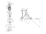
      FIGS. 14 and 15 show intensity and luminance as a function of vertical angle in three horizontal directions: the wall side (“0-deg”), the room side (“180-deg”) and in a vertical plane through the fixture parallel to the wall (“90-deg”). The intensity and luminance documented are the sum of light from any surface that is flashing (reflector, shield or lens). These two figures show that at 90° (i.e., parallel to the wall), the light pattern is not as wide as the pattern on the wall side, but not as narrow as the pattern on the room side. They also show that room-side illumination above 45 vertical degrees is nil. FIGS. 14-16 show uniform vertical illumination on the wall side. FIG. 16 shows uniform lateral illumination of a wall located two feet from a row of fixtures placed three feet on center, and fairly uniform lateral illumination even when the fixtures are placed four feet on center. Similar vertical and lateral wall illumination uniformity occurs when the fixtures are located three feet from a wall.
While a preferred embodiment has been chosen to illustrate the invention, it will be understood by those skilled in the art that various changes and modifications may be made without departing from the scope of the invention as defined by the appended claims. While the preferred embodiment has been described as adapted for recessed mounting in and above a ceiling, it will be appreciated that the features of the invention can also be incorporated in a lighting fixture adapted for exposed surface mounting directly to the underside of a ceiling or other exposed surface, or as a track head fixture, or as a pendent fixture.

Claims (30)

What is claimed is:
1. A wall wash lighting fixture for installation near a wall, comprising:
a light source;
a light pipe below the light source, the light pipe comprising a light-receiving upper end adjacent the light source and a lower end having a slanted light-emitting face with a high point and a low point, the slanted face obliquely facing the wall with said high point closer to the wall than said low point when the lighting fixture is installed; and
a reflector at least partially surrounding the lower end of the light pipe from said high point downward toward said low point, the reflector facing substantially away from the wall when the lighting fixture is installed to redirect a portion of the light emitted by the slanted face of the light pipe away from the wall.
2. The wall wash lighting fixture of claim 1, wherein said slanted face is oval.
3. The wall wash lighting fixture of claim 2, wherein the light pipe comprises a circular cylinder.
4. The wall wash lighting fixture of claim 3, wherein said upper end is substantially circular.
5. The wall wash lighting fixture of claim 3, wherein said slanted face is disposed at an angle of about 45° to a central longitudinal axis of the light pipe.
6. The wall wash lighting fixture of claim 1, wherein the overall length of the light pipe is about 2.5 times its average width.
7. The wall wash lighting fixture of claim 1, wherein said slanted face comprises a plurality of light-refracting elements.
8. The wall wash lighting fixture of claim 7, wherein said slanted face comprises a lenticular array.
9. The wall wash lighting fixture of claim 8, wherein the lenticular array comprises 90° prisms.
10. The wall wash lighting fixture of claim 9, wherein the lenticular array comprises about 75 prisms per inch.
11. The wall wash lighting fixture of claim 1, wherein said slanted face is configured and positioned to emit light toward the wall up to about 83° from the vertical.
12. The wall wash lighting fixture of claim 1, further comprising a shield surrounding the light pipe for substantially preventing lateral leakage of light from the fixture.
13. The wall wash lighting fixture of claim 12, wherein the shield comprises a reflective inner surface for inwardly directing light that escapes from the light pipe before reaching said slanted face.
14. The wall wash lighting fixture of claim 1, wherein the reflector comprises an arcuate reflective surface.
15. The wall wash lighting fixture of claim 14, wherein the reflector completely surrounds the lower end of the light pipe.
16. The wall wash lighting fixture of claim 14, wherein the reflector is configured and positioned such that substantially all of the light it redirects emerges from the fixture below about 45° from the vertical.
17. A wall wash lighting fixture for installation in a ceiling near a wall, comprising:
a housing having a central longitudinal housing axis;
a light source within the housing having a central longitudinal light source axis substantially parallel to and offset from said housing axis;
a light pipe within the housing and below the light source, the light pipe having a central longitudinal light pipe axis substantially coaxial with said light source axis and comprising a light-receiving upper end adjacent the light source and a lower end having a slanted light-emitting face obliquely facing the wall when the lighting fixture is installed; and
a reflector within the housing at least partially surrounding the lower end of the light pipe and facing substantially away from the wall when the lighting fixture is installed to redirect a portion of the light emitted by the slanted face of the light pipe away from the wall, the reflector having a central longitudinal reflector axis substantially coaxial with said housing axis.
18. The wall wash lighting fixture of claim 17, wherein said slanted face is oval.
19. The wall wash lighting fixture of claim 18, wherein the light pipe comprises a circular cylinder.
20. The wall wash lighting fixture of claim 17, wherein said slanted face is disposed at an angle of about 45° to a central longitudinal axis of the light pipe.
21. The wall wash lighting fixture of claim 17, wherein the overall length of the light pipe is about 2.5 times its average width.
22. The wall wash lighting fixture of claim 17, wherein said slanted face comprises a plurality of light-refracting elements.
23. The wall wash lighting fixture of claim 22, wherein said slanted face comprises a lenticular array.
24. The wall wash lighting fixture of claim 23, wherein the lenticular array comprises 90° prisms.
25. The wall wash lighting fixture of claim 24, wherein the lenticular array comprises about 75 prisms per inch.
26. The wall wash lighting fixture of claim 17, wherein said slanted face is configured and positioned to emit light toward the wall up to about 83° from the vertical.
27. The wall wash lighting fixture of claim 17, further comprising a shield surrounding the light pipe for substantially preventing lateral leakage of light from the fixture.
28. The wall wash lighting fixture of claim 17, wherein the reflector comprises an arcuate reflective surface.
29. The wall wash lighting fixture of claim 28, wherein the reflector completely surrounds the lower end of the light pipe.
30. The wall wash lighting fixture of claim 28, wherein the reflector is configured and positioned such that substantially all of the light it redirects emerges from the fixture below about 45° from the vertical.
US13/537,466 2012-06-29 2012-06-29 Small aperture recessed wall wash downlight Active 2032-09-04 US8770779B2 (en)

Priority Applications (1)

Application Number Priority Date Filing Date Title
US13/537,466 US8770779B2 (en) 2012-06-29 2012-06-29 Small aperture recessed wall wash downlight

Applications Claiming Priority (1)

Application Number Priority Date Filing Date Title
US13/537,466 US8770779B2 (en) 2012-06-29 2012-06-29 Small aperture recessed wall wash downlight

Publications (2)

Publication Number Publication Date
US20140003039A1 US20140003039A1 (en) 2014-01-02
US8770779B2 true US8770779B2 (en) 2014-07-08

Family

ID=49777947

Family Applications (1)

Application Number Title Priority Date Filing Date
US13/537,466 Active 2032-09-04 US8770779B2 (en) 2012-06-29 2012-06-29 Small aperture recessed wall wash downlight

Country Status (1)

Country Link
US (1) US8770779B2 (en)

Cited By (7)

* Cited by examiner, † Cited by third party
Publication number Priority date Publication date Assignee Title
US9671076B2 (en) 2015-05-01 2017-06-06 Abl Ip Holding Llc Recessed wall wash light fixture with glare control
US9702522B2 (en) 2015-05-01 2017-07-11 Abl Ip Holding Llc Recessed wall wash light fixture with glare control
US10006605B2 (en) 2014-02-27 2018-06-26 Abl Ip Holding Llc Optical and mechanical assembly for wall wash lighting
USD877956S1 (en) 2017-09-28 2020-03-10 Hubbell Incorporated Luminaire
US10859219B2 (en) 2015-09-25 2020-12-08 Hubbell Incorporated Luminaire
US10948167B2 (en) 2017-11-17 2021-03-16 Hubbell Incorporated Light fixture with adjustable light distribution assembly
US11719398B1 (en) 2022-07-29 2023-08-08 Spectrum Lighting, Inc. Recessed downlight

Families Citing this family (4)

* Cited by examiner, † Cited by third party
Publication number Priority date Publication date Assignee Title
US10591124B2 (en) * 2012-08-30 2020-03-17 Sabic Global Technologies B.V. Heat dissipating system for a light, headlamp assembly comprising the same, and method of dissipating heat
US9348080B1 (en) 2014-11-18 2016-05-24 Quarkstar Llc Wall wash luminaire with light guide and optical element therefore
CN104482461B (en) * 2014-12-09 2017-01-18 济南三星灯饰有限公司 Equipment for disassembling and glue clearing of wall washer lamps
US11466825B2 (en) 2020-01-23 2022-10-11 Signify Holding B.V. Recessed luminaire without an integrated light source

Citations (25)

* Cited by examiner, † Cited by third party
Publication number Priority date Publication date Assignee Title
US3643089A (en) * 1969-07-15 1972-02-15 Century Lighting Inc Lighting fixture for illuminating planar surfaces
US4623956A (en) 1984-08-06 1986-11-18 Conti Mario W Recessed adjustable lighting fixture
DE3737324A1 (en) * 1987-10-30 1989-05-11 Scholz & Kronberg Produktions Low-radiating (deep bowl reflecting) direct luminaire
US5303125A (en) 1993-04-19 1994-04-12 Miller Jack V Fiber optic aimable spotlight luminaire
US5384881A (en) 1993-07-26 1995-01-24 Miller; Jack V. Multi-lens fiber optic luminaire
US5562343A (en) 1994-10-14 1996-10-08 Lightolier Division Of The Genlyte Group Incorporated Multifunctional recessed lighting fixture
US6095669A (en) 1997-08-04 2000-08-01 Ilsung Moolsan Co., Ltd. Recessed lighting fixture for sloped ceilings and baffle received therein
USRE36908E (en) 1995-02-16 2000-10-10 Cooper Industries, Inc. Ceiling mounted wallwash light fixture
US6234640B1 (en) 1998-05-22 2001-05-22 Bruce D. Belfer Fiber optic replicant lamp
US6238065B1 (en) 1996-06-10 2001-05-29 Tenebraex Corporation Non-glaring aesthetically pleasing lighting fixtures
US6547423B2 (en) 2000-12-22 2003-04-15 Koninklijke Phillips Electronics N.V. LED collimation optics with improved performance and reduced size
US6632006B1 (en) 2000-11-17 2003-10-14 Genlyte Thomas Group Llc Recessed wall wash light fixture
US20060002136A1 (en) * 2004-06-30 2006-01-05 Buelow Roger F Ii Adjustable-aim light pipe fixture
US6994456B1 (en) 2004-04-28 2006-02-07 Kurt Versen Company Wall-wash lighting
US6994457B2 (en) 2003-08-13 2006-02-07 Jji Lighting Group, Inc. Recessed downlight lighting apparatus
US7125135B2 (en) 2002-10-30 2006-10-24 Patrick Ward Wall-wash light fixture
US7163329B2 (en) 2003-03-07 2007-01-16 Fiberstars, Inc. Adjustable light pipe fixture
US20070258233A1 (en) 2006-05-04 2007-11-08 Intense Lighting, Llc Single piece dual coating reflector recessed wall wash luminaire
US20080192458A1 (en) * 2007-02-12 2008-08-14 Intematix Corporation Light emitting diode lighting system
US7563004B2 (en) 2006-01-17 2009-07-21 Acuity Brands, Inc. Volumetric downlight light fixture
EP2138874A1 (en) * 2007-09-13 2009-12-30 Kun Dian Photoelectric Enterprise Co. Led lighting fixture
US7789522B2 (en) 2007-08-31 2010-09-07 Hubbell Incorporated Lighting device with a wallwash reflector assembly
US8132944B2 (en) 2008-05-23 2012-03-13 Ruud Lighting, Inc. Recessed LED lighting fixture
US8287142B2 (en) 2008-05-16 2012-10-16 Cree, Inc. Conversion kit for lighting assemblies
US20130241435A1 (en) * 2010-08-20 2013-09-19 Research Triangle Institute, International Lighting devices utilizing optical waveguides and remote light converters, and related methods

Patent Citations (25)

* Cited by examiner, † Cited by third party
Publication number Priority date Publication date Assignee Title
US3643089A (en) * 1969-07-15 1972-02-15 Century Lighting Inc Lighting fixture for illuminating planar surfaces
US4623956A (en) 1984-08-06 1986-11-18 Conti Mario W Recessed adjustable lighting fixture
DE3737324A1 (en) * 1987-10-30 1989-05-11 Scholz & Kronberg Produktions Low-radiating (deep bowl reflecting) direct luminaire
US5303125A (en) 1993-04-19 1994-04-12 Miller Jack V Fiber optic aimable spotlight luminaire
US5384881A (en) 1993-07-26 1995-01-24 Miller; Jack V. Multi-lens fiber optic luminaire
US5562343A (en) 1994-10-14 1996-10-08 Lightolier Division Of The Genlyte Group Incorporated Multifunctional recessed lighting fixture
USRE36908E (en) 1995-02-16 2000-10-10 Cooper Industries, Inc. Ceiling mounted wallwash light fixture
US6238065B1 (en) 1996-06-10 2001-05-29 Tenebraex Corporation Non-glaring aesthetically pleasing lighting fixtures
US6095669A (en) 1997-08-04 2000-08-01 Ilsung Moolsan Co., Ltd. Recessed lighting fixture for sloped ceilings and baffle received therein
US6234640B1 (en) 1998-05-22 2001-05-22 Bruce D. Belfer Fiber optic replicant lamp
US6632006B1 (en) 2000-11-17 2003-10-14 Genlyte Thomas Group Llc Recessed wall wash light fixture
US6547423B2 (en) 2000-12-22 2003-04-15 Koninklijke Phillips Electronics N.V. LED collimation optics with improved performance and reduced size
US7125135B2 (en) 2002-10-30 2006-10-24 Patrick Ward Wall-wash light fixture
US7163329B2 (en) 2003-03-07 2007-01-16 Fiberstars, Inc. Adjustable light pipe fixture
US6994457B2 (en) 2003-08-13 2006-02-07 Jji Lighting Group, Inc. Recessed downlight lighting apparatus
US6994456B1 (en) 2004-04-28 2006-02-07 Kurt Versen Company Wall-wash lighting
US20060002136A1 (en) * 2004-06-30 2006-01-05 Buelow Roger F Ii Adjustable-aim light pipe fixture
US7563004B2 (en) 2006-01-17 2009-07-21 Acuity Brands, Inc. Volumetric downlight light fixture
US20070258233A1 (en) 2006-05-04 2007-11-08 Intense Lighting, Llc Single piece dual coating reflector recessed wall wash luminaire
US20080192458A1 (en) * 2007-02-12 2008-08-14 Intematix Corporation Light emitting diode lighting system
US7789522B2 (en) 2007-08-31 2010-09-07 Hubbell Incorporated Lighting device with a wallwash reflector assembly
EP2138874A1 (en) * 2007-09-13 2009-12-30 Kun Dian Photoelectric Enterprise Co. Led lighting fixture
US8287142B2 (en) 2008-05-16 2012-10-16 Cree, Inc. Conversion kit for lighting assemblies
US8132944B2 (en) 2008-05-23 2012-03-13 Ruud Lighting, Inc. Recessed LED lighting fixture
US20130241435A1 (en) * 2010-08-20 2013-09-19 Research Triangle Institute, International Lighting devices utilizing optical waveguides and remote light converters, and related methods

Non-Patent Citations (2)

* Cited by examiner, † Cited by third party
Title
DL5ZP Recessed LED Downlight, Lucifer Lighting Company, 2011.
NanoLED Wall Wash Trim Round LN10RWT, USAI Lighting, 2010.

Cited By (10)

* Cited by examiner, † Cited by third party
Publication number Priority date Publication date Assignee Title
US10006605B2 (en) 2014-02-27 2018-06-26 Abl Ip Holding Llc Optical and mechanical assembly for wall wash lighting
US9671076B2 (en) 2015-05-01 2017-06-06 Abl Ip Holding Llc Recessed wall wash light fixture with glare control
US9702522B2 (en) 2015-05-01 2017-07-11 Abl Ip Holding Llc Recessed wall wash light fixture with glare control
US10859219B2 (en) 2015-09-25 2020-12-08 Hubbell Incorporated Luminaire
USD877956S1 (en) 2017-09-28 2020-03-10 Hubbell Incorporated Luminaire
USD904664S1 (en) 2017-09-28 2020-12-08 Hubbell Incorporated Luminaire
USD954331S1 (en) 2017-09-28 2022-06-07 Hubbell Incorporated Luminaire
US10948167B2 (en) 2017-11-17 2021-03-16 Hubbell Incorporated Light fixture with adjustable light distribution assembly
US11549663B2 (en) 2017-11-17 2023-01-10 HLI Solutions, Inc. Light fixture with adjustable light distribution assembly
US11719398B1 (en) 2022-07-29 2023-08-08 Spectrum Lighting, Inc. Recessed downlight

Also Published As

Publication number Publication date
US20140003039A1 (en) 2014-01-02

Similar Documents

Publication Publication Date Title
US8770779B2 (en) Small aperture recessed wall wash downlight
US8602601B2 (en) LED downlight retaining ring
KR101289752B1 (en) Led lamp
JP5702784B2 (en) Daylight lighting apparatus and method with auxiliary lighting fixture
RU2459142C1 (en) Street lamp based on light diodes
US20110170298A1 (en) LED Downlight with Improved Light Output
JP4657248B2 (en) lighting equipment
WO2011111622A1 (en) Illumination apparatus
US20110026249A1 (en) Low profile LED lighting assembly
JP6453549B2 (en) lighting equipment
US20110310603A1 (en) Light fixtures
JP2010102913A (en) Illumination fixture
JP6072785B2 (en) Optical waveguide
JP6118317B2 (en) Optical waveguide
US9683717B1 (en) Asymmetric area lens for low-profile lighting system
JP4902006B2 (en) Lighting device
KR100910112B1 (en) Shedding area expansion led lamp
WO2018228224A1 (en) Lamp
JP5116865B2 (en) Lighting device
KR101459273B1 (en) Protrusive diffusion cover type recessed down light fixture
KR102020984B1 (en) Led lighting apparatus with indirect lighting type
KR101115549B1 (en) Ighting apparatus controllable lighting position
JP6429672B2 (en) Light emitting device and lighting apparatus using the same
US20190211975A1 (en) Bulbs with indirect illumination
KR101710596B1 (en) Lighting apparatus

Legal Events

Date Code Title Description
AS Assignment

Owner name: HUBBELL INCORPORATED, CONNECTICUT

Free format text: ASSIGNMENT OF ASSIGNORS INTEREST;ASSIGNORS:STEADMAN, CONNIE;WILCOX, SHAWN;REEL/FRAME:028923/0846

Effective date: 20120827

STCF Information on status: patent grant

Free format text: PATENTED CASE

FEPP Fee payment procedure

Free format text: SURCHARGE FOR LATE PAYMENT, LARGE ENTITY (ORIGINAL EVENT CODE: M1554)

MAFP Maintenance fee payment

Free format text: PAYMENT OF MAINTENANCE FEE, 4TH YEAR, LARGE ENTITY (ORIGINAL EVENT CODE: M1551)

Year of fee payment: 4

MAFP Maintenance fee payment

Free format text: PAYMENT OF MAINTENANCE FEE, 8TH YEAR, LARGE ENTITY (ORIGINAL EVENT CODE: M1552); ENTITY STATUS OF PATENT OWNER: LARGE ENTITY

Year of fee payment: 8

AS Assignment

Owner name: HUBBELL LIGHTING, INC., CONNECTICUT

Free format text: NUNC PRO TUNC ASSIGNMENT;ASSIGNOR:HUBBELL INCORPORATED;REEL/FRAME:058838/0162

Effective date: 20220112

AS Assignment

Owner name: ALLY BANK, AS COLLATERAL AGENT, NEW YORK

Free format text: SECURITY AGREEMENT;ASSIGNORS:HUBBELL LIGHTING, INC.;LITECONTROL CORPORATION;CURRENT LIGHTING SOLUTIONS, LLC;AND OTHERS;REEL/FRAME:058982/0844

Effective date: 20220201

AS Assignment

Owner name: ATLANTIC PARK STRATEGIC CAPITAL FUND, L.P., AS COLLATERAL AGENT, NEW YORK

Free format text: SECURITY INTEREST;ASSIGNORS:HUBBELL LIGHTING, INC.;LITECONTROL CORPORATION;CURRENT LIGHTING SOLUTIONS, LLC;AND OTHERS;REEL/FRAME:059034/0469

Effective date: 20220201

AS Assignment

Owner name: ALLY BANK, AS COLLATERAL AGENT, NEW YORK

Free format text: CORRECTIVE ASSIGNMENT TO CORRECT THE PATENT NUMBER 10841994 TO PATENT NUMBER 11570872 PREVIOUSLY RECORDED ON REEL 058982 FRAME 0844. ASSIGNOR(S) HEREBY CONFIRMS THE SECURITY AGREEMENT;ASSIGNORS:HUBBELL LIGHTING, INC.;LITECONTROL CORPORATION;CURRENT LIGHTING SOLUTIONS, LLC;AND OTHERS;REEL/FRAME:066355/0455

Effective date: 20220201

AS Assignment

Owner name: ATLANTIC PARK STRATEGIC CAPITAL FUND, L.P., AS COLLATERAL AGENT, NEW YORK

Free format text: CORRECTIVE ASSIGNMENT TO CORRECT THE PATENT NUMBER PREVIOUSLY RECORDED AT REEL: 059034 FRAME: 0469. ASSIGNOR(S) HEREBY CONFIRMS THE SECURITY INTEREST;ASSIGNORS:HUBBELL LIGHTING, INC.;LITECONTROL CORPORATION;CURRENT LIGHTING SOLUTIONS, LLC;AND OTHERS;REEL/FRAME:066372/0590

Effective date: 20220201