US8765322B2 - Fuel cell support structure and method of assembly/disassembly thereof - Google Patents
Fuel cell support structure and method of assembly/disassembly thereof Download PDFInfo
- Publication number
- US8765322B2 US8765322B2 US13/126,779 US200813126779A US8765322B2 US 8765322 B2 US8765322 B2 US 8765322B2 US 200813126779 A US200813126779 A US 200813126779A US 8765322 B2 US8765322 B2 US 8765322B2
- Authority
- US
- United States
- Prior art keywords
- support structure
- cell stack
- stack assembly
- fitting
- connector
- Prior art date
- Legal status (The legal status is an assumption and is not a legal conclusion. Google has not performed a legal analysis and makes no representation as to the accuracy of the status listed.)
- Active, expires
Links
Images


Classifications
-
- H—ELECTRICITY
- H01—ELECTRIC ELEMENTS
- H01M—PROCESSES OR MEANS, e.g. BATTERIES, FOR THE DIRECT CONVERSION OF CHEMICAL ENERGY INTO ELECTRICAL ENERGY
- H01M8/00—Fuel cells; Manufacture thereof
- H01M8/24—Grouping of fuel cells, e.g. stacking of fuel cells
- H01M8/2465—Details of groupings of fuel cells
-
- H—ELECTRICITY
- H01—ELECTRIC ELEMENTS
- H01M—PROCESSES OR MEANS, e.g. BATTERIES, FOR THE DIRECT CONVERSION OF CHEMICAL ENERGY INTO ELECTRICAL ENERGY
- H01M8/00—Fuel cells; Manufacture thereof
- H01M8/02—Details
-
- H—ELECTRICITY
- H01—ELECTRIC ELEMENTS
- H01M—PROCESSES OR MEANS, e.g. BATTERIES, FOR THE DIRECT CONVERSION OF CHEMICAL ENERGY INTO ELECTRICAL ENERGY
- H01M8/00—Fuel cells; Manufacture thereof
- H01M8/24—Grouping of fuel cells, e.g. stacking of fuel cells
- H01M8/2465—Details of groupings of fuel cells
- H01M8/247—Arrangements for tightening a stack, for accommodation of a stack in a tank or for assembling different tanks
-
- Y—GENERAL TAGGING OF NEW TECHNOLOGICAL DEVELOPMENTS; GENERAL TAGGING OF CROSS-SECTIONAL TECHNOLOGIES SPANNING OVER SEVERAL SECTIONS OF THE IPC; TECHNICAL SUBJECTS COVERED BY FORMER USPC CROSS-REFERENCE ART COLLECTIONS [XRACs] AND DIGESTS
- Y02—TECHNOLOGIES OR APPLICATIONS FOR MITIGATION OR ADAPTATION AGAINST CLIMATE CHANGE
- Y02E—REDUCTION OF GREENHOUSE GAS [GHG] EMISSIONS, RELATED TO ENERGY GENERATION, TRANSMISSION OR DISTRIBUTION
- Y02E60/00—Enabling technologies; Technologies with a potential or indirect contribution to GHG emissions mitigation
- Y02E60/30—Hydrogen technology
- Y02E60/50—Fuel cells
Definitions
- This disclosure relates to a fuel cell installation in which access to connections may be difficult. More particularly, the disclosure relates to a support structure used in conjunction with removable cell stack assemblies.
- One type of proton exchange membrane cell stack assembly includes internal manifolds having opposing end plates secured to one another to load the cell stack assembly components.
- the end plates include electrical fittings and fluid fittings used to supply and return the fuel, reactant and coolant.
- the cell stack assemblies that that can be easily installed and removed relative to a support structure.
- One such arrangement requires installation of the cell stack assemblies in a direction along its length with one of the end plates inserted into the support structure first.
- the electrical and fluid connections are difficult to achieve.
- the connections must be made blind with limited space for tools or hands to access, align, and secure the fittings on the end plate to the connections provided at the support structure.
- the cell stack assemblies are likewise difficult to remove from the support structures.
- a fuel cell installation includes a support structure and a cell stack assembly that is removably insertable into the support structure from an uninstalled position to an installed position during an installation procedure.
- the cell stack assembly includes a fitting.
- An interfacing structure is mounted on one of the support structure in the cell stack assembly.
- the interfacing structure carries a connector that is configured to receive the fitting in interconnected relationship.
- At least one of the fitting and the connector floats in a plane relative to the support structure during the installation procedure.
- the fitting engages the connector when the cell stack assembly is inserted into the support structure.
- the fitting is repositioned relative to the connector to ensure that the fitting and connector are aligned with one another and connected upon installation.
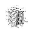
- FIG. 1 is a perspective view of a rear of a fuel cell assembly, in accordance with an embodiment of the disclosure.
- FIG. 2 is an enlarged perspective view of a portion of the fuel cell assembly shown in FIG. 1 .
- FIG. 3 is an enlarged perspective view of a fuel cell assembly, in accordance with another embodiment of the disclosure.
- FIG. 4 is a cross-sectional view of the fuel cell assembly shown in FIG. 3 taken along line 4 - 4 .
- FIG. 5 is a cross-sectional view of a portion of the interfacing structure shown in FIG. 3 taken along line 5 - 5 .
- FIG. 6 is a cross-sectional view of the interfacing structure taken along line 6 - 6 in FIG. 5 .
- FIG. 7 is a schematic view of a front end of the fuel cell installation shown in FIG. 3 .
- a fuel cell assembly 10 is shown in FIG. 1 .
- the fuel cell assembly 10 includes multiple cell stack assemblies 12 that are installed into a support structure 14 constructed of a framework of vertical and horizontal members 16 , 18 , for example.
- Each cell stack assembly 12 includes opposing front and rear ends 20 , 22 that apply a clamping load to fuel cell components, such as anodes, cathodes and membrane electrode assemblies.
- the cell stack assembly 12 includes proton exchange membranes and porous plates having internal manifolds, which provide fuel and reactant to fuel and reactant flow fields in the anode and the cathode.
- the support structure 14 includes spaced apart support brackets 23 , which have an L-shaped cross-section in one example, for slidably receiving and supporting the cell stack assemblies 12 .
- each cell stack assembly 12 is removably inserted into the support structure 14 in a direction D (z-direction in FIGS. 2 and 4 ) from an uninstalled position to an installed position during an installation procedure.
- the rear end 22 is inserted first into the support structure 14 .
- the rear end 22 includes an end plate 26 having one or more fluid and/or electrical fittings 28 , 30 .
- the fluid and electrical fittings 28 , 30 are not visible during installation and cannot be easily accessed so that the fluid and electrical fittings 28 , 30 must be connected blind to their respective fluid and electrical connectors 50 , 48 .
- an interfacing structure 24 is used to align the fittings and connectors while the cell stack assembly 12 is installed into the support structure 14 .
- the fittings 28 , 30 are male and the connectors 48 , 50 are female.
- the fittings could be female and the connectors could be male.
- the female connectors are coaxial with the male fittings and circumscribe or surround them.
- the connections provided between the male and female fittings and connectors may be of any suitable type, such as bulkhead, push-to-connect, face seal, radial o-ring seal, flat gasket, pressurized seal, or any other connection configuration that is misalignment tolerant.
- the fuel cell installation includes the support structure 14 .
- the cell stack assembly 12 is removably inserted into the support structure 14 from an uninstalled position where the fittings 28 , 30 and connectors 48 , 50 are not fully connected (not shown) to an installed position (illustrated in the Figures), during an installation procedure.
- the cell stack assembly 12 include the fittings 28 , 30 in the disclosed example.
- the interfacing structure 24 is mounted on either the support structure 14 or the cell stack assembly 12 .
- the interfacing structure 24 carries connectors 48 , 50 in the disclosed example in an interconnector relationship. At least one of the fittings and the connectors are moveable in a plane (x-y) relative to the support structure 14 during the installation procedure.
- the interfacing structure 24 includes a plate 32 that floats relative to the support structure 14 .
- FIG. 2 is an enlarged view of the right column of cell stack assemblies.
- the plate 32 is not shown at the upper right cell stack assembly in FIGS. 1 and 2 for clarity. Some of the supporting structure for the plate 32 is also omitted for clarity from the topmost and middle cell stack assemblies in the right column of cell stack assemblies.
- the movable plate 32 enables the cell stack assembly 12 to be aligned with the support structure 14 as the cell stack assembly 12 is slid rearward during installation. Movement of the plate 32 also provides a rough alignment between the fittings and connectors. As shown in FIG. 2 , the plate 32 and support structure 14 includes interlocking features provided by flanges 36 and fasteners 33 .
- the flanges 36 include slotted apertures 38 that receive the fasteners 33 secured to the plate 32 , which permit limited movement of the plate 32 in an x-y plane.
- a mounting bracket 40 is secured to one of the horizontal members 18 .
- the mounting bracket 40 includes an aperture 42 that houses a bearing 44 .
- a pin 34 extends from the end plate 26 and is received by the bearing 44 , which carries the weight of the rear end 22 and aligns the end plate 26 relative to the support structure 14 by tilting as needed.
- the plate 32 includes an opening 43 through which the pin 34 extends.
- the plate 32 also has openings 46 that accommodate the electrical fittings 30 .
- the rightmost electrical connector 48 is omitted for clarity.
- the electrical and fluid connectors 48 , 50 are carried by the plate 32 in the example and are permitted to float in the plane of the plate 32 , enabling additional movement and alignment between the fittings and connectors during installation.
- the installation direction z is generally perpendicular to the plane (x-y) of the plate 32 in the examples shown.
- the fluid and electrical fittings 28 , 30 correspondingly engage the fluid and electrical connectors 50 , 48 and reposition the electrical and fluid fittings 48 , 50 and plate 32 , as needed, to more precisely align the fittings and connectors with one another.
- FIGS. 3 and 4 Another example cell stack assembly 110 is shown in FIGS. 3 and 4 .
- Protrusions 56 extending from either side of the cell stack assemblies 112 are slidable on the support brackets 123 .
- the mounting bracket 140 is supported on the horizontal member 118 (secured between vertical members 116 ) and houses a spherical bearing 144 .
- a dielectric bushing 58 is secured to the plate 132 in opening 143 with a retainer 59 .
- the bushing 58 includes a tapered opening 60 for receiving a tapered end of the pin 134 during installation.
- the plate 132 of the interfacing structure 124 includes apertures 65 that are slightly larger than the outer diameter of the fluid fittings 128 , which extend from the rear plate 126 at the rear end 122 .
- the fluid connectors 150 include lip 62 and retainer 64 for axially locating the fluid connections 150 while permitting them to float in the x-y plane during installation to enable alignment of the fluid fittings 128 relative to the fluid connectors 150 .
- an O-ring 66 is used between the fitting and connectors to seal them relative to one another.
- the plate 132 includes one or more pins 68 having ends that are received in slotted apertures 70 in the horizontal member 118 , which provide interlocking features that permit constrained rotation R of the plate 132 relative to the support structure 114 during installation.
- the fluid fittings 150 provide a coolant inlet and outlet.
- the connections are made “blind” at the rear end 122 as described above.
- Fuel inlet and outlet 72 , 74 and reactant inlet and outlet 76 , 78 are provided at the front end 120 in the example shown, as illustrated in FIG. 7 .
- the connections at the front end 120 can be made using traditional connection techniques, for example, since the fittings and connectors at the front end 120 are not obscured or obstructed.
Abstract
Description
Claims (8)
Applications Claiming Priority (1)
| Application Number | Priority Date | Filing Date | Title |
|---|---|---|---|
| PCT/US2008/082385 WO2010053474A1 (en) | 2008-11-05 | 2008-11-05 | Fuel cell support structure and method of assembly/disassembly thereof |
Related Parent Applications (1)
| Application Number | Title | Priority Date | Filing Date |
|---|---|---|---|
| PCT/US2008/082385 A-371-Of-International WO2010053474A1 (en) | 2008-11-05 | 2008-11-05 | Fuel cell support structure and method of assembly/disassembly thereof |
Related Child Applications (1)
| Application Number | Title | Priority Date | Filing Date |
|---|---|---|---|
| US14/283,085 Division US9478821B2 (en) | 2008-11-05 | 2014-05-20 | Methods of installing cell stack assemblies |
Publications (2)
| Publication Number | Publication Date |
|---|---|
| US20110200908A1 US20110200908A1 (en) | 2011-08-18 |
| US8765322B2 true US8765322B2 (en) | 2014-07-01 |
Family
ID=42153113
Family Applications (2)
| Application Number | Title | Priority Date | Filing Date |
|---|---|---|---|
| US13/126,779 Active 2029-12-20 US8765322B2 (en) | 2008-11-05 | 2008-11-05 | Fuel cell support structure and method of assembly/disassembly thereof |
| US14/283,085 Active 2028-11-08 US9478821B2 (en) | 2008-11-05 | 2014-05-20 | Methods of installing cell stack assemblies |
Family Applications After (1)
| Application Number | Title | Priority Date | Filing Date |
|---|---|---|---|
| US14/283,085 Active 2028-11-08 US9478821B2 (en) | 2008-11-05 | 2014-05-20 | Methods of installing cell stack assemblies |
Country Status (2)
| Country | Link |
|---|---|
| US (2) | US8765322B2 (en) |
| WO (1) | WO2010053474A1 (en) |
Families Citing this family (2)
| Publication number | Priority date | Publication date | Assignee | Title |
|---|---|---|---|---|
| WO2013081575A1 (en) * | 2011-11-28 | 2013-06-06 | Utc Power Corporation | Fuel cell seal retainer assembly |
| JP6014571B2 (en) * | 2012-12-07 | 2016-10-25 | 本田技研工業株式会社 | Fuel cell stack |
Citations (16)
| Publication number | Priority date | Publication date | Assignee | Title |
|---|---|---|---|---|
| US5403679A (en) | 1992-06-15 | 1995-04-04 | Gnb Industrial Battery Co. | Modular battery cabinet assembly |
| US5532072A (en) | 1993-07-24 | 1996-07-02 | Dornier Gmbh | Serially arranged fuel cells for large scale power generation |
| US5626984A (en) | 1995-11-16 | 1997-05-06 | Albini; Salvatore | Battery terminal system |
| US5741605A (en) | 1996-03-08 | 1998-04-21 | Westinghouse Electric Corporation | Solid oxide fuel cell generator with removable modular fuel cell stack configurations |
| US6030718A (en) | 1997-11-20 | 2000-02-29 | Avista Corporation | Proton exchange membrane fuel cell power system |
| US6096449A (en) | 1997-11-20 | 2000-08-01 | Avista Labs | Fuel cell and method for controlling same |
| US6110612A (en) | 1999-04-19 | 2000-08-29 | Plug Power Inc. | Structure for common access and support of fuel cell stacks |
| US6387556B1 (en) | 1997-11-20 | 2002-05-14 | Avista Laboratories, Inc. | Fuel cell power systems and methods of controlling a fuel cell power system |
| US6632556B2 (en) | 2000-12-19 | 2003-10-14 | Utc Fuel Cells, Llc | Manifold assembly for a fuel cell power plant |
| US6794069B1 (en) | 1999-10-12 | 2004-09-21 | Reveo, Inc. | Fuel cell support and electrical interconnector |
| US6844100B2 (en) | 2002-08-27 | 2005-01-18 | General Electric Company | Fuel cell stack and fuel cell module |
| US7063912B2 (en) | 2002-11-01 | 2006-06-20 | Deere & Company | Fuel cell assembly system |
| US7147953B2 (en) | 2002-06-24 | 2006-12-12 | Delphi Technologies, Inc. | Dual fuel cell stacks connected in series electrically and in parallel for gas flow |
| USRE39556E1 (en) | 1997-11-20 | 2007-04-10 | Relion, Inc. | Fuel cell and method for controlling same |
| US7323270B2 (en) | 2004-08-11 | 2008-01-29 | Fuelcell Energy, Inc. | Modular fuel-cell stack assembly |
| WO2008049204A1 (en) | 2006-10-23 | 2008-05-02 | Hydrogenics Corporation | Frame system and electrochemical cell system having the frame system |
Family Cites Families (1)
| Publication number | Priority date | Publication date | Assignee | Title |
|---|---|---|---|---|
| US7494736B2 (en) * | 2004-12-23 | 2009-02-24 | Fuelcell Energy, Inc. | Dielectric frame assembly and fuel cell manifold |
-
2008
- 2008-11-05 WO PCT/US2008/082385 patent/WO2010053474A1/en active Application Filing
- 2008-11-05 US US13/126,779 patent/US8765322B2/en active Active
-
2014
- 2014-05-20 US US14/283,085 patent/US9478821B2/en active Active
Patent Citations (18)
| Publication number | Priority date | Publication date | Assignee | Title |
|---|---|---|---|---|
| US5403679A (en) | 1992-06-15 | 1995-04-04 | Gnb Industrial Battery Co. | Modular battery cabinet assembly |
| US5532072A (en) | 1993-07-24 | 1996-07-02 | Dornier Gmbh | Serially arranged fuel cells for large scale power generation |
| US5626984A (en) | 1995-11-16 | 1997-05-06 | Albini; Salvatore | Battery terminal system |
| US5741605A (en) | 1996-03-08 | 1998-04-21 | Westinghouse Electric Corporation | Solid oxide fuel cell generator with removable modular fuel cell stack configurations |
| US6387556B1 (en) | 1997-11-20 | 2002-05-14 | Avista Laboratories, Inc. | Fuel cell power systems and methods of controlling a fuel cell power system |
| US6096449A (en) | 1997-11-20 | 2000-08-01 | Avista Labs | Fuel cell and method for controlling same |
| US6218035B1 (en) | 1997-11-20 | 2001-04-17 | Avista Laboratories, Inc. | Proton exchange membrane fuel cell power system |
| US6030718A (en) | 1997-11-20 | 2000-02-29 | Avista Corporation | Proton exchange membrane fuel cell power system |
| USRE39556E1 (en) | 1997-11-20 | 2007-04-10 | Relion, Inc. | Fuel cell and method for controlling same |
| US6773839B2 (en) | 1997-11-20 | 2004-08-10 | Relion, Inc. | Fuel cell power systems and methods of controlling a fuel cell power system |
| US6110612A (en) | 1999-04-19 | 2000-08-29 | Plug Power Inc. | Structure for common access and support of fuel cell stacks |
| US6794069B1 (en) | 1999-10-12 | 2004-09-21 | Reveo, Inc. | Fuel cell support and electrical interconnector |
| US6632556B2 (en) | 2000-12-19 | 2003-10-14 | Utc Fuel Cells, Llc | Manifold assembly for a fuel cell power plant |
| US7147953B2 (en) | 2002-06-24 | 2006-12-12 | Delphi Technologies, Inc. | Dual fuel cell stacks connected in series electrically and in parallel for gas flow |
| US6844100B2 (en) | 2002-08-27 | 2005-01-18 | General Electric Company | Fuel cell stack and fuel cell module |
| US7063912B2 (en) | 2002-11-01 | 2006-06-20 | Deere & Company | Fuel cell assembly system |
| US7323270B2 (en) | 2004-08-11 | 2008-01-29 | Fuelcell Energy, Inc. | Modular fuel-cell stack assembly |
| WO2008049204A1 (en) | 2006-10-23 | 2008-05-02 | Hydrogenics Corporation | Frame system and electrochemical cell system having the frame system |
Non-Patent Citations (2)
| Title |
|---|
| International Preliminary Report on Patentability for International application No. PCT/US2008/082385 mailed May 19, 2011. |
| International Search Report and Written Opinion of the International Searching Authority for International application No. PCT/US2008/082385 mailed Jun. 26, 2009. |
Also Published As
| Publication number | Publication date |
|---|---|
| US20140255823A1 (en) | 2014-09-11 |
| US9478821B2 (en) | 2016-10-25 |
| US20110200908A1 (en) | 2011-08-18 |
| WO2010053474A1 (en) | 2010-05-14 |
Similar Documents
| Publication | Publication Date | Title |
|---|---|---|
| US6372372B1 (en) | Clamping system for a fuel cell stack | |
| CN100593878C (en) | Structure of a fuel cell stack | |
| US9187833B2 (en) | Internally-reinforced water electrolyser module | |
| US11283098B2 (en) | System for high-temperature tight coupling of a stack having SOEC/SOFC-type solid oxides | |
| US11031608B2 (en) | Connecting element for electrically contact-connecting separator plates of a fuel cell stack | |
| US6426159B1 (en) | Sealing method and apparatus for a fuel cell stack | |
| CN110513553B (en) | Floating fluid connector and fluid connector assembly | |
| JP6014571B2 (en) | Fuel cell stack | |
| US9133553B2 (en) | Externally-reinforced water electrolyzer module | |
| US9478821B2 (en) | Methods of installing cell stack assemblies | |
| US9373857B2 (en) | Fuel cell apparatus | |
| CN105655609A (en) | Internal positioning structure used for assembly of fuel cell electric pile | |
| KR100778634B1 (en) | Fuel cell, fuel cell seperator in the same and fuel cell stack including the same | |
| EP2692011B1 (en) | Cell stack system | |
| US11387468B2 (en) | Separator plate having spacer element and fuel cell system | |
| US20070154770A1 (en) | End plate for an electrochemical cell stack | |
| JP2017147090A (en) | Fuel battery stack | |
| US20180309152A1 (en) | Fuel battery stack | |
| US6562506B1 (en) | Fuel-cell system with a pivotable stack installation assembly | |
| CN220376796U (en) | End plate of water electrolyser | |
| CN215766829U (en) | Tool checking fixture for fuel cell stack distribution manifold | |
| CN219959144U (en) | Battery module and battery box | |
| CN220131967U (en) | Hydrogen-rich water device and water heater | |
| CN218254731U (en) | Fixture tool | |
| US20070141437A1 (en) | Removing and installing a fuel cell stack |
Legal Events
| Date | Code | Title | Description |
|---|---|---|---|
| AS | Assignment |
Owner name: UTC POWER CORPORATION, CONNECTICUT Free format text: ASSIGNMENT OF ASSIGNORS INTEREST;ASSIGNORS:BLONDIN, SEAN M.;FINK, GARRETT W.;LOVE, ROBERT A.;AND OTHERS;SIGNING DATES FROM 20081031 TO 20081104;REEL/FRAME:026222/0066 |
|
| AS | Assignment |
Owner name: UNITED TECHNOLOGIES CORPORATION, CONNECTICUT Free format text: ASSIGNMENT OF ASSIGNORS INTEREST;ASSIGNOR:UTC POWER CORPORATION;REEL/FRAME:031033/0325 Effective date: 20130626 |
|
| AS | Assignment |
Owner name: BALLARD POWER SYSTEMS INC., CANADA Free format text: ASSIGNMENT OF ASSIGNORS INTEREST;ASSIGNOR:UNITED TECHNOLOGIES CORPORATION;REEL/FRAME:032916/0923 Effective date: 20140424 |
|
| STCF | Information on status: patent grant |
Free format text: PATENTED CASE |
|
| AS | Assignment |
Owner name: AUDI AG, GERMANY Free format text: ASSIGNMENT OF ASSIGNORS INTEREST;ASSIGNOR:BALLARD POWER SYSTEMS INC.;REEL/FRAME:035716/0253 Effective date: 20150506 |
|
| AS | Assignment |
Owner name: AUDI AG, GERMANY Free format text: CORRECTIVE ASSIGNMENT TO CORRECT ASSIGNEE ADDRESS PREVIOUSLY RECORDED AT REEL 035716, FRAME 0253. ASSIGNOR(S) HEREBY CONFIRMS THE ASSIGNMENT;ASSIGNOR:BALLARD POWER SYSTEMS INC.;REEL/FRAME:036448/0093 Effective date: 20150506 |
|
| MAFP | Maintenance fee payment |
Free format text: PAYMENT OF MAINTENANCE FEE, 4TH YEAR, LARGE ENTITY (ORIGINAL EVENT CODE: M1551) Year of fee payment: 4 |
|
| MAFP | Maintenance fee payment |
Free format text: PAYMENT OF MAINTENANCE FEE, 8TH YEAR, LARGE ENTITY (ORIGINAL EVENT CODE: M1552); ENTITY STATUS OF PATENT OWNER: LARGE ENTITY Year of fee payment: 8 |