US8745014B2 - Time series data mapping into a key-value database - Google Patents
Time series data mapping into a key-value database Download PDFInfo
- Publication number
- US8745014B2 US8745014B2 US13/277,054 US201113277054A US8745014B2 US 8745014 B2 US8745014 B2 US 8745014B2 US 201113277054 A US201113277054 A US 201113277054A US 8745014 B2 US8745014 B2 US 8745014B2
- Authority
- US
- United States
- Prior art keywords
- key
- time
- value
- event
- duration
- Prior art date
- Legal status (The legal status is an assumption and is not a legal conclusion. Google has not performed a legal analysis and makes no representation as to the accuracy of the status listed.)
- Active, expires
Links
Images


Classifications
-
- G—PHYSICS
- G06—COMPUTING; CALCULATING OR COUNTING
- G06F—ELECTRIC DIGITAL DATA PROCESSING
- G06F16/00—Information retrieval; Database structures therefor; File system structures therefor
- G06F16/20—Information retrieval; Database structures therefor; File system structures therefor of structured data, e.g. relational data
- G06F16/24—Querying
- G06F16/245—Query processing
- G06F16/2458—Special types of queries, e.g. statistical queries, fuzzy queries or distributed queries
- G06F16/2477—Temporal data queries
Definitions
- Time series data may include data points that are measured over time.
- One example of generating time series data may be the recordation by a web server of the times when users access web pages.
- a logging function in a web server may capture time series data that includes a time value and an identifier (e.g., pathname, etc.) for a particular web page within the web site.
- the captured time series data may then be analyzed by a web server administrator over periods of time. For example, the web server administrator may desire to determine the number of times a particular web page of a web site was visited over a specific time range (e.g., over the last week, etc.).
- Time series data is typically stored in a relational database or a database where row scans are allowed.
- the web server can store data relating to the visit in a table of a relational database where each row in the table represents a separate visit to the web server.
- the first column of the table may store the actual time value and the second column of the table may store the pathname of the visited web page within the web site.
- the administrator can formulate a query for (and ultimately issue the query to) the relational database that specifies the range of values for the specified time as well as the pathname of the web page.
- the relational database can scan the rows of the table to determine how many entries have time values (e.g., first column values) within the time range and have a pathname (e.g., second column values) corresponding to the web page. The number of times the web page was visited within the time frame then equals the number of determined rows from the query. While allowing arbitrary time ranges to be queried is useful, storing data in a relational database may have disadvantages, such as scalability and operational complexity.
- a method for storing time series data in a key-value database includes receiving time series data relating to the occurrence of an event.
- An addressing scheme that defines attributes for inclusion in keys for the event is analyzed.
- the attributes include a plurality of time granularity attributes of different sizes.
- the method generates at least one key corresponding to the time series data based on the analyzing of the addressing scheme.
- the at least one key includes a plurality of attributes specified in the addressing scheme that are related to the event and one of the attributes represents one of the plurality of time granularity attributes.
- the method further issues a corresponding command to the key-value database to store a record of the occurrence of the event as a value in the key-value database in association with the generated key where stored values in the key-value database corresponding to the plurality of keys may be used to satisfy queries relating to the event over a range of time.
- a non-transitory computer-readable storage medium containing instructions configured to store time series data in a key-value database for controlling a computer system to be operable to: receive time series data relating to the occurrence of an event; analyze an addressing scheme that defines attributes for inclusion in keys for the event, wherein the attributes include a plurality of time granularity attributes of different sizes; generate at least one key corresponding to the time series data based on the analyzing of the addressing scheme, wherein the at least one key includes a plurality of attributes specified in the addressing scheme that are related to the event and one of the attributes represents one of the plurality of time granularity attributes; and for each generated key, issue a corresponding command to the key-value database to store a record of the occurrence of the event as a value in the key-value database in association with the generated key, wherein stored values in the key-value database corresponding to the plurality of keys may be used to satisfy queries relating to the event over a range of time.
- an apparatus configured to store time series data in a key-value database
- the computer-readable medium includes instructions for controlling the one or more computer processors to be operable to: receive time series data relating to the occurrence of an event; analyze an addressing scheme that defines attributes for inclusion in keys for the event, wherein the attributes include a plurality of time granularity attributes of different sizes; generate at least one key corresponding to the time series data based on the analyzing of the addressing scheme, wherein the at least one key includes a plurality of attributes specified in the addressing scheme that are related to the event and one of the attributes represents one of the plurality of time granularity attributes; and for each generated key, issue a corresponding command to the key-value database to store a record of the occurrence of the event as a value in the key-value database in association with the generated key, wherein stored values in the key-value database corresponding to the plurality of keys may be used to satisfy queries relating to the event
- FIG. 1 depicts a simplified system for storing time series data according to one embodiment.
- FIG. 2 shows an example of the addressing scheme according to one embodiment.
- FIG. 3 depicts a simplified flowchart for mapping from the time domain into a key-value domain according to one embodiment.
- FIG. 4 depicts a simplified flowchart of a method for eagerly rolling up time series data according to one embodiment.
- FIG. 5 shows an example of eagerly rolling up time series data according to one embodiment.
- FIG. 6 depicts a simplified flowchart of a method for processing a time range query according to one embodiment.
- FIG. 7 shows an example of selecting time windows in a time dimension hierarchy according to one embodiment.
- FIG. 8 depicts a more detailed example of a service node according to one embodiment.
- FIG. 9 depicts a more detailed example of a key-value database according to one embodiment.
- FIG. 1 depicts a simplified system 100 for storing time series data according to one embodiment.
- a client tier 101 includes one or more clients 102 .
- Clients 102 may be producers of time series data or consumers of time series data.
- One example of a producer client 102 is a web server hosting an ecommerce web site or application that is configured to log or store time series data relating to objects (e.g., color, shape, time purchased, etc.).
- An example of a consumer client 102 may be a management application used by an administrator of the web site, such as the Spring Insight administration tool from SpringSource, that may be used to analyze the behavior and performance of the ecommerce web site and respond to such questions as “how many red cubes were sold in the month of January on the web site.”
- Key-value database 106 includes computing machines that store keys and the keys' associated values. Examples of a database that may be utilized as a key-value store or database 106 is VMware's vFabricTM Gemfire® platform, Apache Cassandra, CouchDB, HBase and other known key-value stores, although it should be recognized that any databases, including relational database such as MySQL, etc., may be utilized as a key-value database 106 in embodiments.
- a service tier 103 includes one or more service nodes 104 that receive time series data from producer clients 102 .
- Service nodes 104 include one or more distributed computers that provide a service to producer clients 102 to store data in key-value database 106 .
- Such a service node 104 maps or otherwise transforms the “raw” time series data into a key-value format that can be issued to and stored in key-value database 106 .
- Service nodes 104 also receive “time domain” queries (e.g., that request data occurring within a certain time range, such as the number of visits to a web page during a specified period of time, etc.) from consumer clients 102 and map or otherwise transform such queries into one or more “key-value” queries that can actually be issued to and satisfied by key-value database 106 .
- time domain queries e.g., that request data occurring within a certain time range, such as the number of visits to a web page during a specified period of time, etc.
- Key-value database 106 stores data in key-value pairs.
- key-value database 106 may include database management servers that support key-value commands, for example, to insert or delete key-value data into database 106 , find or query for values stored in database 106 by providing corresponding keys, or adjust values of key-value data in database 106 (e.g., incrementing, decrementing or otherwise modifying already-stored values of key-value data, etc.).
- key-value database 106 may be distributed and stored key-value pairs may be spread across many computing machines.
- service nodes 104 map time series data produced by producer clients 102 into key-value pairs for storage in key-value database 106 .
- an administrator may develop an “addressing scheme” that can be used by service nodes 104 to interpret received time series data in order to generate corresponding keys for key-value database 106 .
- the administrator may pre-determine the structure of keys that should be generated by service nodes 104 while in alternative embodiments, service nodes 104 may generate keys based on information in the addressing scheme provided by the administrator.
- service node 104 When service node 104 receives time series data from a producer client 102 , service node 104 consults the addressing scheme to determine what “attributes” should be incorporated into a key corresponding to the received time series data. For example, if a producer client 102 transmits to service node 104 times series data indicating that a red cube was sold on the ecommerce web site at 12:00 pm on Jan. 1 st , service node 104 may consult its addressing scheme to determine that attributes relating to color, shape and time should be captured in a generated key. As such, service node 104 then generates a key of “(red, cube, January 1 st : 1 day)” corresponding to the received time series data.
- This key can then be used by service node 104 to submit a command to key-value database 106 to keep track of the number of red cubes (e.g., the “value” of a key-value pair, as further discussed herein) that have been sold to date on January 1 st .
- red cubes e.g., the “value” of a key-value pair, as further discussed herein
- Such a data collection process enables the offering of a subsequent query processing capability to allow a consumer client 102 to submit time domain queries to service node 104 , wherein the consumer client 102 submits a query with a time range, such as “how many red cubes were sold in January.”
- service node 104 may generate one or more key-value queries for keys in database 106 .
- a query for a key of “(red, cube, January 1 st : 1 day)” may be one query.
- Database 106 would return the number of red cubes sold on January 1 st .
- service node 104 may submit additional queries for keys for the other days of the months (e.g., queries for each other day or queries for blocks of days).
- an addressing scheme as previously referred to, that is used by service node 102 to map or otherwise transform between time domain queries into one or more key-value queries that can be submitted to key-value database 106 will be described.
- an addressing scheme for a particular data set may be specified by an administrator (e.g., administrator of the ecommerce web site, etc.) and provided to service node 104 in order to map or translate time series data (e.g., description of objects sold on the ecommerce website over time, etc.) generated by a producer client 102 (e.g., ecommerce web server, etc.) into one or more key-value commands (increment, insert, modify, etc.) that may be issued to key-value database 106 .
- Such an addressing scheme may define attributes for a key.
- the key of a key-value pair generated by service node 104 upon receipt of time series data from producer client 102 may be an N-tuple of attributes corresponding to a vector within a hypercube.
- Each attribute of the N-tuple key may belong to a different dimension (e.g., color dimension, shape dimension and time dimension for sold objects, etc.).
- the value of attributes in an N-tuple key may be dependent upon a “hierarchy” specified in the addressing scheme for the dimension to which the attribute belongs.
- a hierarchy for the time dimension may be represented by different granularity layers of time windows (e.g., a 1 day granularity, a 2 day granularity, etc.).
- FIG. 2 shows an example of a specified addressing scheme according to one embodiment.
- the particular data set corresponding to the addressing scheme relates to attributes of objects that are sold on an ecommerce web site.
- service node 104 may consult the addressing scheme to determine the specified attributes for a key and generate a key 202 that may include three attributes that correspond to the dimensions of color, shape, and time.
- the color dimension is the color of a sold object and the shape dimension is the shape of the sold object.
- the time dimension expresses a period of time in which the object was sold.
- Service node 102 may further generate a new value 204 or request modification of a pre-existing value 204 that is already stored in database 106 in association with key 202 .
- value 204 is a scalar value (e.g., counter) representing the number of objects having the color and shape attributes specified in key 202 that have been sold within the time attribute specified in key 202 . It should be recognized that in alternative embodiments, value 204 may be represented by rich statistics (e.g., a histogram), serialized objects, or other types of rich data rather than scalar values.
- service node 104 may generate a key-value pair having a key of “(red, cube, January 1 st : 1 day)” and a value of 1 to indicate that one red cube was just sold.
- service node 104 would then issue either an “insert” key-value command to add the key-value pair to database 106 , or a “modify” or “increment” key-value command to database 106 to update the current value of the key value pair stored in database 106 .
- increment is generally used herein, it should be recognized that service node 104 may issue commands to modify a value, such as modifying a value from 3 to 10 if 7 red cubes are sold within a time window.
- the color, shape, and time dimension are hierarchical, with a hierarchy 206 - 1 for the color dimension, a hierarchy 206 - 2 for the shape dimension, and a hierarchy 206 - 3 for the time dimension.
- Color dimension hierarchy 206 - 1 and shape dimension hierarchy 206 - 2 are arranged in a hierarchical directed graph. For example, a “Red” node is a child of a “Primary” node under a root node of “All”. Also, a “Cube” node is a child of a root node “All”.
- Time dimension hierarchy 206 - 3 of FIG. 2 is represented by different time granularity layers.
- Each granularity layer includes time windows of a different size.
- each granularity layer contains time windows that are a multiple of the size (i.e., time period) of the previous layer.
- the granularities are 1 day, 2 day, 4 day, and 8 day, but other time windows may be used.
- the time window may be based on a start time and a duration. For example, for the 1 day granularity layer, a time window 208 - 1 may start on January 1 and last for 1 day. Also, for the 2 day granularity layer, a time window 208 - 2 may start on January 1 and last for 2 days.
- Time windows 208 - 3 and 208 - 4 for the 4 day and 8 day granularities respectively start on January 1 and last for 4 days and 8 days.
- the next time window in each granularity layer starts when the previous time window ends. For example, in the 2 day granularity window, the next time window starts on January 3 and lasts for 2 days.
- a time window starting on January 2 nd and lasting for 2 days does not exist. In this case, time windows in a specific granularity layer do not overlap. However, in other embodiments, overlapping time windows may be used in a single granularity layer.
- an administrator may specify a pre-determined structure for keys in the addressing scheme that may be generated by service node 104 .
- the administrator may specify in the addressing scheme that keys generated by service node 104 include shape, color and time attributes.
- service node 104 consults the addressing scheme and generates a key with a pre-determined structure of “(red, cube, January 1 st : 1 day).”
- the addressing scheme may provide a number of flexible options for generating keys depending upon the nature of the time series data received.
- service node 104 may generate multiple key-value commands (e.g., insert, modify, etc.) to key-value database 106 in order to store the time series data in key-value database 106 .
- These multiple key-value commands may correspond to different time granularity layers of the specified time dimension hierarchy (e.g., time dimension hierarchy 206 - 3 ) and facilitate retrieval of data from database 106 when consumer clients 102 issue time series queries.
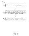
- FIG. 3 depicts a simplified flowchart 300 for transforming time series data into key-value pairs according to one embodiment.
- service node 104 receives time series data from producer client 102 .
- Such received time series data may include a time value relating to a time when such data was received and a metric value relating to a standard of measurement that an administrator desires to track.
- received time series data may include the specific time that a number of red cubes have been purchased at an ecommerce web site (e.g., the specific time being the time value and the number of red cubes being the metric value).
- service node 104 transforms the received time series data into one or more key-value pairs to be transmitted to key-value database 106 for storage. For example, service node 104 may consult an addressing scheme for the data set that was specified by the administrator (as discussed above) to determine the number of attributes of dimensions (e.g., color, shape and time, etc.) in a generated key that corresponds to the time series data. In one example, when producer client 102 determines that a red cube was sold at 3 PM on January 1 st , the time value for the sale and data relating to the nature of the object sold (e.g., red and cube) are logged. Producer client 102 then transmits such time series data to service node 104 , for example, through an application programmer interface (API) provided by service node 104 .
- API application programmer interface
- service node 104 If the received time series data indicates that a red cube was just sold (e.g., at 3 PM on January 1 st , etc.) and the specified addressing scheme indicates that the finest time granularity is a time window of 1 day, then service node 104 generates a key of “(red, cube, January 1 st : 1 day)” and a value of “1” indicating that a single red cube was just sold as indicated by the time series data.
- service node 104 may then issue commands to database 106 to store the above generated key-value pair in database 106 .
- service node 104 may either insert a new key 202 into database 106 or modify a value of an existing key 202 in database 106 .
- Service node 104 may keep track of inserted keys 202 (and also which computing machines the keys are stored on, which is described later). If a key 202 has not been created in database 106 , service node 104 may issue an “insert” or similar command to key-value database 106 to insert the key-value pair, such as [(red, cube, January 1 st : 1 day), 1] into database 106 .
- service node 104 may issue a “modify” or similar command to key-value database 106 to modify (e.g., increment, decrement, merge, etc.) the current value stored in database 106 .
- modify e.g., increment, decrement, merge, etc.
- the value stored in association with the key acts as a counter (e.g., total number of red cube sales on January 1 st )
- the counter for the key is incremented.
- service node 104 may “eagerly roll up” time series data received from producer clients 102 along one or more dimensions by issuing multiple commands to database 106 for a particular time series data.
- FIG. 4 depicts a simplified flowchart 400 of a method for eagerly rolling up time series data according to one embodiment.
- service node 104 generates a first command for a first key at a first granularity layer in which the time series data is applicable.
- such a first command may be the previously discussed insert command for the key-value pair, [(red, cube, January 1 st : 1 day), 1] or if a counter is the metric being used, then an increment command for the generated key, (red, cube, January 1 st : 1 day) that increments a pre-existing stored value for the generated key.
- service node 104 if service node 104 has not been configured to perform “eager roll ups,” then at 406 , service node 104 simply issues the previously discussed insert or increment command to database 106 .
- service node 104 uses a roll up algorithm to determine whether higher levels of hierarchies for various dimensions may be utilized to generate additional key-value pairs.
- the addressing scheme may indicate to service node 104 that “eager roll-up” should be performed and that multiple granularity levels along the time dimension should be “rolled up.” For example, referring to the addressing scheme of FIG.
- service node 104 may generate additional commands to issue to database 106 for higher time granularities such as 2 days (red, cube, January 1 st : 2 days), 4 days (red, cube, January 1 st : 4 days) and 8 days (red, cube, January 1 st : 8 days) time windows.
- service node 104 generates and issues commands for the keys in the higher granularity levels.
- the values corresponding to keys that have higher level time attributes are incremented by database 106 according to commands issued by service node 104 .
- service node 104 may be further configured (e.g., as indicated by the addressing scheme in one embodiment) to eagerly roll up along the hierarchy of the color dimension of FIG. 2 , thereby generating additional insert or modify commands for database 106 utilizing keys such as (primary, cube, January 1 st : 1 day), (all, cube, January 1 st : 1 day), (primary, cube, January 1 st : 2 days), etc.
- service node 104 may enable time domain queries issued by consumer clients 102 to be satisfied by fewer generated key-value queries to database 106 .
- service node 104 may be able to satisfy the time domain query by transforming it into a single key-value query having a key associated with the 8-day range (e.g., (red, cube, January 1 st : 8 days), if the time series data was eagerly rolled up to the 8 day granularity layer.
- service node 104 may use an algorithm to balance the time taken to eagerly roll up data versus time domain query processing time to determine how many granularity layers in which to roll up the time series data (or other key attributes). That is, more eager roll-up of data may mean less time processing queries.
- FIG. 5 shows an example of eagerly rolling up time series data according to one embodiment.
- key-value database 106 For each time granularity layer, key-value database 106 includes a number of keys. A single key is associated with a time window. Thus, for an eight day period starting on January 1st, eight 1-day keys, four 2-day keys, two 4-day keys, and one 8-day key may exist. An example is shown for the first two keys of four different granularity layers.
- key-value database 106 includes key-value pairs for keys 202 - 1 - 202 - 4 that are each associated with a different granularity layer for the time dimension. For example, the time dimension is shown at 504 where the time windows start at January 1 st and cover 1, 2, 4, and 8 day periods.
- key-value database 106 includes keys 202 - 5 - 202 - 8 that are the next keys in the four granularity layers.
- the start date is different for each time window due to the different time windows used in the first key 202 of each granularity layer.
- the granularity is 1 day and thus the time dimension for the next key in this granularity layer starts at January 2 nd and ends 1 day later. This is because key 202 - 1 covered the day of January 1 st and key 202 - 5 covers the next day starting at January 2 nd .
- the time dimension starts on January 3 rd and ends 2 days later. In this case, key 202 - 2 covers January 1 st through January 2 nd and key 202 - 6 covers January 3 rd through January 4 th .
- An administrator uses the above process to determine these keys, and other keys for other time windows.
- service node 104 or database 106 may be configured to perform “lazy roll-ups” of time series data. For example, rather than generating multiple keys (e.g., for different time granularities or higher level nodes of a dimensions hierarchy) and issuing multiple commands to database 106 upon receipt of time series data from producer client 104 , service node 104 or database 106 may generate such multiple keys and issue corresponding commands subsequent to receipt of the time series data by service node 104 , for example, through a batch mode process. As further discussed below, alternatively or in addition, roll-ups may also be performed by service node 104 or database 106 lazily upon receipt of certain queries.
- key-value database 106 includes a key 202 - 9 which aggregates along the shape dimension as the member for that dimension is ‘All’, a parent to other dimension members. In this case, all red toys sold regardless of shape for the 16-day period starting January 1 st are aggregated for key 202 - 9 .
- Key 202 - 10 aggregates along the color and shape dimensions to count all toys regardless of color or shape for the 16-day period starting on January 1 st .
- Key-value database 106 modifies a value 204 when key-value database 106 receives a command for a key 202 .
- key-value database 106 receives an increment command for a key 202 .
- key-value database 106 is shown including values 204 - 1 - 204 - 10 with a zero value.
- these keys 202 may not be stored in database 106 until service node 104 generates key 202 and inserts key 202 into database 202 . For example, until a red cube is sold in the month of January, database 106 may not be storing keys 202 shown. However, keys 202 are shown for discussion purposes.
- a red cube may be sold.
- service node 104 When time series data is recorded for this transaction, service node 104 generates commands for keys 202 to eagerly roll up the time series data to some or all granularity layers. In other embodiments, the time series data may not be eagerly rolled up, but in this example, time series data is rolled up to all granularity layers.
- Service node 104 generates commands for keys 202 - 1 , 202 - 2 , 202 - 3 , and 202 - 4 , which have the applicable time window for a red cube sold on January 1 st .
- key-value database 106 increments values 204 - 1 , 204 - 2 , 204 - 3 , and 204 - 4 for each of these keys to “1”. However, values 204 - 5 , 204 - 6 , 204 - 7 , and 204 - 8 for keys 202 - 5 , 202 - 6 , 202 - 7 , and 202 - 8 remain at 0 because the time windows for these keys start on January 2 nd or later and thus a red cube sold on January 1 st is not applicable for these time windows. Also, key-value database 106 increments values 204 - 9 and 204 - 10 for the aggregation along the color and shape dimensions.
- Key-value database 106 increments value 204 - 5 for key 202 - 5 because the red cube has been sold on January 2 nd and applies to this 1-day time window. Key-value database 106 does not increment value 204 - 1 for key 202 - 1 because the time window for key 202 - 1 ended on January 1 st . Also, key-value database 106 does not increment values 204 for keys 202 - 6 , 202 - 7 , and 202 - 8 because the time windows start after January 2 nd . Values 204 - 9 and 204 - 10 for the aggregation along the color and shape dimensions are again incremented. This process continues as additional time series data is received.
- service nodes 104 In addition to collecting time series data from producer clients 102 and mapping the time series data into key-value data in database 106 , service nodes 104 also receive and process time domain queries issued by consumer clients 102 . Each service node 104 may process queries independently of one another.
- a time domain query typically includes a time range such as “how many red cubes were sold in January?” Because data is stored in database 106 in accordance with keys having attributes consistent with a specified addressing scheme, a single key to satisfy an arbitrary time range (e.g., 31 days beginning from January 1 st ) may not exist. As such, service node 104 may break up a time series query into multiple key-value queries corresponding to keys consistent with the time granularity layers of the specified addressing scheme.
- service node 104 translates a time domain query for the number of red cubes sold in January into 31 separate key-value queries (for 31 days in January) corresponding to keys associated with each day in January (i.e., using the finest granularity layer in FIG. 1 of 1 day).
- service node 104 can sum up the values to calculate an answer to the time domain query.
- eager roll ups as previously discussed, were performed by service node 104
- different time windows in different granularity layers may be used by service node 104 to satisfy the time domain query. For example, in an eager roll-up configuration, rather than generating 31 key-value queries, service node 104 may generate 6 key-value queries for three 8-day time windows, a 4-day time window, a 2-day time window, and a 1-day time window.
- FIG. 6 depicts a simplified flowchart 600 of a method for processing a time domain query according to one embodiment.
- service node 104 utilizes an algorithm to traverse the different granularity layers of the addressing scheme to determine which time windows to use. For example, a “best fit” algorithm may be used to determine an optimal fit of time windows. The best fit algorithm may balance which granularity layers to use based on criteria, such as accuracy or query processing speed.
- service node 104 receives a time domain query specifying a time range such as “January 1-7-days”. In addition to the time range, other dimension values may be specified, such as “red” and “cube.”
- service node 104 issues key-value queries to database 106 for keys associated with the selected time windows. For example, three key-value queries for keys 202 associated with time windows 306 , 308 , and 310 are issued to key-value database 106 .
- service node 104 receives values 204 for the queries from key-value database 106 .
- service node 104 generates a time domain query result based on values 204 returned for the key-value queries. For example, the received values 204 may be summed or accumulated for the time windows and then returned to consumer client 102 .
- the above example found time windows that precisely fit the time range; however, it should be recognized that sometimes the time windows may not precisely fit the time range.
- the best fit algorithm may be used to determine time windows that can most accurately determine the result while balancing the number of queries needed. In some cases, the best fit algorithm may not determine time windows that exactly cover the time range. For example, interpolation may be used to estimate portions of the time range not covered by a key 202 . Also, the accuracy required may not need every portion of the time range to be accounted for by a key 202 . Additionally, the number of queries may be reduced by leveraging time windows that may extend into the future.
- a 4-day period that includes the last 3 days and a day in the future may be selected instead of a 2-day period and a 1-day period. This is because the value for the 1 day in the future is 0 and thus, the 4-day period really includes the data for the last 3 days. This may reduce the number of queries required by using higher granularity layers to satisfy a query.
- service node 104 may perform lazy roll-ups upon receipt of certain queries instead of or in addition to eager roll-ups or batch-based lazy roll-ups as previously discussed. For example, service node 104 may receive a time domain query from a consumer client 102 relating to the question, “how many red objects were sold on January 1 st ?” By consulting the addressing scheme, service node 104 may initially generate a key-value query such as “GET (red, all, January 1 st : 1 day)” which corresponds to the time domain query. However, if eager roll ups or batch-based lazy roll ups have not been previously performed for such data, database 106 may indicate that no value is associated with such a key.
- GET red, all, January 1 st : 1 day
- service node 104 may further consult the addressing scheme in order to generate additional key-value queries relating to lower layer attributes for the shape dimension hierarchy. For example, service node 104 may generate two separate key-value queries for database 106 based on the lowest layer of the shape dimension hierarchy (e.g., cube and ball): (i) GET (red, cube, January 1 st : 1 day) and (ii) GET (red, ball, January 1 st : 1 day). Upon receiving values for these two queries, service node 104 can add them up and return the result to consumer client 102 .
- the lowest layer of the shape dimension hierarchy e.g., cube and ball
- service node 104 can further insert the result into database 106 (or cache the value) corresponding to the key (red, all, January 1 st : 1 day) such that a response for a subsequent query for the key will be immediately available, rather than requiring a traversal by service node 104 through the hierarchies of the addressing schema.
- FIG. 8 depicts a more detailed example of a service node 104 according to one embodiment.
- a time series data (TSD) processor 802 receives time series data from producer clients 102 and generates keys 202 for the time series data by consulting a specified addressing scheme developed by an administrator. Such an addressing scheme, as previously discussed, may specify to service node 104 which pre-determined keys 202 to select based on a number of attributes (e.g., color, shape, and time).
- a write command generator 806 generates key-value commands (e.g., insert, modify, etc.) based on the generated keys to transmit to key-value database 106 .
- a time domain query processor 808 receives time domain queries from consumer clients 102 and generates one or more key-value queries to issue to database 106 in order to satisfy the time domain queries. For example, time domain query processor 808 applies a best fit algorithm that determines time windows that are considered the best fit for the time range.
- a read command generator 810 generates key-value queries for key-value database 106 and sends the key-value queries to key-value database 106 .
- Result processor 812 receives values 204 for the queries from key-value database 106 , and determines a result for the time range query. For example, the returned values 204 may be summed or accumulated. Result processor 812 then returns the result to a consumer client 102 .
- FIG. 9 depicts a more detailed example of key-value database 106 according to one embodiment.
- Different computing machines 902 may be used to store key-value pairs.
- key-value database 106 may be sharded across multiple machines, where sharding distributes the key-values among the machines in a cluster of machines.
- Service nodes 104 may insert keys 202 such that keys for a specific granularity layer exist on one machine 902 and not another.
- a machine 902 - 1 includes key 202 - 1 and key 202 - 5 and corresponding values for those keys for the 1 day granularity layer.
- machine 902 - 2 includes key 202 - 2 and key 202 - 6 for the 2-day granularity layer;
- machine 902 - 3 includes keys 202 - 3 and 202 - 7 for the 4-day granularity layer; and
- machine 902 - 4 includes keys 202 - 4 and 202 - 8 for the 8-day granularity layer.
- a database management server 904 manages queries for keys 202 and modifying of values 204 .
- Service node 104 may route key-value queries to different machines 902 depending on where keys 202 are located. This may be different from doing a row scan of a single table when using a relational database. For example, particular embodiments may query for key 202 - 3 in machine 902 - 3 and key 202 - 6 in machine 902 - 2 .
- service node 104 maps from the time domain to the key-value domain, flexibility to store the data in different storage technologies may be provided. For example, because key value databases are a lowest common denominator for storing data, different storage technologies can support the key-value format. Also, because service node 104 retrieves the data using key-value semantics, the queries remain simple and row scans do not need to be performed. Granularity layers also provide faster response time to queries.
- an administrator may want to measure web site performance.
- producer client 102 captured the time the web site was visited.
- Service node 104 generates a command for the visit (response time could also be measured, but is not described).
- the command is an increment command for a key that is an N-tuple.
- the key includes the attributes of “Application name”, “Server name”, and “Time”.
- the time dimension indicates a time window in which the web site was visited in a finest granularity layer.
- Service node 104 may resolve the command to other commands for higher granularity layers.
- Key-value database 106 receives these commands and increments the applicable values for the keys.
- a user may then query for various time ranges. For example, service node 104 receives a query asking for all visits in a time range for “Application # 1 ” associated with Server # 1 ′′. Service node 104 determines keys for different granularities for the time range and queries for those keys are performed. Service node 104 sums or accumulates results from the key-value queries to determine the number of web site visits in the time range for Application # 1 using Server # 1 .
- the various embodiments described herein may employ various computer-implemented operations involving data stored in computer systems. For example, these operations may require physical manipulation of physical quantities—usually, though not necessarily, these quantities may take the form of electrical or magnetic signals, where they or representations of them are capable of being stored, transferred, combined, compared, or otherwise manipulated. Further, such manipulations are often referred to in terms, such as producing, identifying, determining, or comparing. Any operations described herein that form part of one or more embodiments may be useful machine operations.
- one or more embodiments also relate to a device or an apparatus for performing these operations. The apparatus may be specially constructed for specific required purposes, or it may be a general purpose computer selectively activated or configured by a computer program stored in the computer.
- various general purpose machines may be used with computer programs written in accordance with the teachings herein, or it may be more convenient to construct a more specialized apparatus to perform the required operations.
- One or more embodiments may be implemented as one or more computer programs or as one or more computer program modules embodied in one or more computer readable storage media.
- the term computer readable storage medium refers to any data storage device that can store data which can thereafter be input to a computer system—computer readable media may be based on any existing or subsequently developed technology for embodying computer programs in a manner that enables them to be read by a computer.
- Examples of a non-transitory computer readable medium include a hard drive, network attached storage (NAS), read-only memory, random-access memory (e.g., a flash memory device), a CD (Compact Discs)—CD-ROM, a CD-R, or a CD-RW, a DVD (Digital Versatile Disc), a magnetic tape, and other optical and non-optical data storage devices.
- the computer readable medium can also be distributed over a network coupled computer system so that the computer readable code is stored and executed in a distributed fashion.
Abstract
Description
Claims (21)
Priority Applications (1)
| Application Number | Priority Date | Filing Date | Title |
|---|---|---|---|
| US13/277,054 US8745014B2 (en) | 2011-10-19 | 2011-10-19 | Time series data mapping into a key-value database |
Applications Claiming Priority (1)
| Application Number | Priority Date | Filing Date | Title |
|---|---|---|---|
| US13/277,054 US8745014B2 (en) | 2011-10-19 | 2011-10-19 | Time series data mapping into a key-value database |
Publications (2)
| Publication Number | Publication Date |
|---|---|
| US20130103658A1 US20130103658A1 (en) | 2013-04-25 |
| US8745014B2 true US8745014B2 (en) | 2014-06-03 |
Family
ID=48136833
Family Applications (1)
| Application Number | Title | Priority Date | Filing Date |
|---|---|---|---|
| US13/277,054 Active 2032-05-07 US8745014B2 (en) | 2011-10-19 | 2011-10-19 | Time series data mapping into a key-value database |
Country Status (1)
| Country | Link |
|---|---|
| US (1) | US8745014B2 (en) |
Cited By (10)
| Publication number | Priority date | Publication date | Assignee | Title |
|---|---|---|---|---|
| US20150032775A1 (en) * | 2013-07-26 | 2015-01-29 | Metamarkets Group Inc. | Segment data visibility and management in a distributed database of time stamped records |
| CN105426482A (en) * | 2015-11-20 | 2016-03-23 | 华东交通大学 | Figure-database integrated HBase transfer storage method of massive monitoring information of 10kV railway power distribution network |
| US9613109B2 (en) | 2015-05-14 | 2017-04-04 | Walleye Software, LLC | Query task processing based on memory allocation and performance criteria |
| US20170177636A1 (en) * | 2015-12-18 | 2017-06-22 | Cisco Technology, Inc. | Fast circular database |
| US10002154B1 (en) | 2017-08-24 | 2018-06-19 | Illumon Llc | Computer data system data source having an update propagation graph with feedback cyclicality |
| CN108595578A (en) * | 2018-04-17 | 2018-09-28 | 曙光信息产业(北京)有限公司 | Data processing method, device and the storage system of high-performance calculation Historical Jobs data |
| CN110471914A (en) * | 2019-06-27 | 2019-11-19 | 苏宁云计算有限公司 | The associated method and system of dimension in a kind of real time data processing |
| US10897402B2 (en) | 2019-01-08 | 2021-01-19 | Hewlett Packard Enterprise Development Lp | Statistics increment for multiple publishers |
| US20220398243A1 (en) * | 2017-11-15 | 2022-12-15 | Sumo Logic, Inc. | Key name synthesis |
| US11586623B2 (en) * | 2018-02-28 | 2023-02-21 | Vmware, Inc. | Efficient time-range queries on databases in distributed computing systems |
Families Citing this family (45)
| Publication number | Priority date | Publication date | Assignee | Title |
|---|---|---|---|---|
| US9436710B2 (en) * | 2010-09-28 | 2016-09-06 | Redis Labs Ltd. | Systems, methods, and media for managing an in-memory NoSQL database |
| US8904047B1 (en) * | 2012-06-29 | 2014-12-02 | Emc Corporation | Cloud capable storage system with high perormance nosql key-value pair operating environment |
| CN103793439B (en) * | 2012-11-05 | 2019-01-15 | 腾讯科技(深圳)有限公司 | A kind of real-time retrieval information acquisition method, device and server |
| US9384221B2 (en) | 2013-06-25 | 2016-07-05 | Google Inc. | Unlimited retroactive data element dimension widening |
| CN103390038B (en) * | 2013-07-16 | 2016-03-30 | 西安交通大学 | A kind of method of structure based on HBase and retrieval increment index |
| US9128965B1 (en) | 2013-08-07 | 2015-09-08 | Amazon Technologies, Inc. | Configurable-capacity time-series tables |
| US9529827B2 (en) | 2013-09-03 | 2016-12-27 | Acxiom Corporation | Change value database system and method |
| WO2015065435A1 (en) * | 2013-10-31 | 2015-05-07 | Hewlett-Packard Development Company, L.P. | Storing time series data for a search query |
| US9584395B1 (en) | 2013-11-13 | 2017-02-28 | Netflix, Inc. | Adaptive metric collection, storage, and alert thresholds |
| CN104636389B (en) * | 2013-11-14 | 2018-03-27 | 博雅网络游戏开发(深圳)有限公司 | Realize the method and system of Hbase database real-time queries |
| CN103701778A (en) * | 2013-12-11 | 2014-04-02 | 清华大学 | System and method for protecting privacy information in mobile terminal |
| CN104778182B (en) * | 2014-01-14 | 2018-03-02 | 博雅网络游戏开发(深圳)有限公司 | Data lead-in method and system based on HBase |
| US20150261830A1 (en) * | 2014-03-11 | 2015-09-17 | Adrian Capdefier | Automated data mining |
| WO2015167562A1 (en) | 2014-04-30 | 2015-11-05 | Hewlett-Packard Development Company, L.P. | Using local memory nodes of a multicore machine to process a search query |
| CN104008134B (en) * | 2014-05-06 | 2017-02-15 | 武汉邮电科学研究院 | Efficient storage method and system based on Hbase |
| US9619548B2 (en) | 2014-05-20 | 2017-04-11 | Google Inc. | Dimension widening aggregate data |
| CN104050271A (en) * | 2014-06-23 | 2014-09-17 | 桂林长海科技有限责任公司 | Bayonet data processing method based on HBase |
| WO2016010901A1 (en) * | 2014-07-14 | 2016-01-21 | CRAM Worldwide, Inc. | Data conversion device |
| US9779100B2 (en) | 2014-07-14 | 2017-10-03 | Secured2 Corporation | Data conversion method |
| US9779148B2 (en) | 2014-07-14 | 2017-10-03 | Secured2 Corporation | Data conversion system |
| US9779101B2 (en) | 2014-07-14 | 2017-10-03 | Secured2 Corporation | Data conversion device |
| CN104268280B (en) * | 2014-10-17 | 2017-07-07 | 中国人民解放军国防科学技术大学 | A kind of Hierarchical storage and querying method based on key value database |
| CN104361090B (en) * | 2014-11-17 | 2018-01-05 | 浙江宇视科技有限公司 | Data query method and device |
| US9740633B2 (en) | 2015-01-07 | 2017-08-22 | International Business Machines Corporation | Updatable address lookup application program interface |
| CN104598567B (en) * | 2015-01-12 | 2018-01-09 | 北京中交兴路车联网科技有限公司 | A kind of method of the data statistics re-scheduling based on Hadoop MapReduce programming frameworks |
| CN105005617B (en) * | 2015-07-21 | 2018-10-12 | 领航动力信息系统有限公司 | A kind of storage method and device of time series data |
| CN105072366B (en) * | 2015-08-18 | 2018-12-07 | 浙江宇视科技有限公司 | A kind of generation method and device of video data table |
| US11803562B2 (en) * | 2016-06-29 | 2023-10-31 | Yahoo Assets Llc | Method and system for querying streaming data |
| US11435713B2 (en) * | 2016-07-28 | 2022-09-06 | Aveva Software, Llc | Summarization retrieval in a process control environment |
| CN106682077B (en) * | 2016-11-18 | 2020-06-09 | 山东鲁能软件技术有限公司 | Mass time sequence data storage implementation method based on Hadoop technology |
| US9832274B1 (en) * | 2017-04-27 | 2017-11-28 | Bluecore, Inc. | Directory update monitoring systems and methods |
| CN107943981A (en) * | 2017-11-30 | 2018-04-20 | 努比亚技术有限公司 | HBase rows paging method, server and computer-readable recording medium |
| CN109271597B (en) * | 2018-09-19 | 2022-02-18 | 郑州云海信息技术有限公司 | Method and device for paging display of multi-table scene of non-relational database |
| US11100071B2 (en) * | 2018-10-10 | 2021-08-24 | Micron Technology, Inc. | Key-value store tree data block spill with compaction |
| US10915546B2 (en) | 2018-10-10 | 2021-02-09 | Micron Technology, Inc. | Counter-based compaction of key-value store tree data block |
| US10852978B2 (en) | 2018-12-14 | 2020-12-01 | Micron Technology, Inc. | Key-value store using journaling with selective data storage format |
| US10936661B2 (en) | 2018-12-26 | 2021-03-02 | Micron Technology, Inc. | Data tree with order-based node traversal |
| US11645628B2 (en) * | 2019-05-16 | 2023-05-09 | Microsoft Technology Licensing, Llc | Translation of time between calendar systems |
| CN110457341A (en) * | 2019-07-03 | 2019-11-15 | 平安科技(深圳)有限公司 | Data aggregation method, device, computer equipment and storage medium |
| CN110347726A (en) * | 2019-07-17 | 2019-10-18 | 帷幄匠心科技(杭州)有限公司 | A kind of efficient time series data is integrated to store inquiry system and method |
| CN110597829B (en) * | 2019-11-12 | 2020-03-27 | 深圳竹云科技有限公司 | Method, device and equipment for generating primary key |
| US11514405B1 (en) | 2021-05-14 | 2022-11-29 | Microsoft Technology Licensing, Llc | Map calendar graphical user interface with dynamic time mold functionality |
| US11681424B2 (en) | 2021-05-14 | 2023-06-20 | Microsoft Technology Licensing, Llc | Map calendar graphical user interface with content-variable view levels |
| US11886453B2 (en) * | 2021-10-29 | 2024-01-30 | Splunk Inc. | Quantization of data streams of instrumented software and handling of delayed or late data |
| CN114116739B (en) * | 2021-11-10 | 2023-06-20 | 浪潮卓数大数据产业发展有限公司 | System for inserting key value data into column type database and implementation method |
Citations (9)
| Publication number | Priority date | Publication date | Assignee | Title |
|---|---|---|---|---|
| US20030028546A1 (en) * | 2001-06-13 | 2003-02-06 | International Business Machines Corporation | Technique for determination of an exception in multi-dimensional data |
| US20050128201A1 (en) * | 2003-12-12 | 2005-06-16 | Warner Michael S. | Method and system for system visualization |
| US20060252016A1 (en) * | 2003-05-07 | 2006-11-09 | Takafumi Terasawa | Schedule creation method, schedule creation system, unexperienced schedule prediction method, and learning schedule evaluation display method |
| US20070079195A1 (en) * | 2005-08-31 | 2007-04-05 | Ken Ueno | Time-series data analyzing apparatus |
| US20090112927A1 (en) * | 2007-10-26 | 2009-04-30 | Upendra Chitnis | System and Method of Transforming Data for Use in Data Analysis Tools |
| US20090281839A1 (en) * | 2002-05-17 | 2009-11-12 | Lawrence A. Lynn | Patient safety processor |
| US20100235334A1 (en) * | 2003-01-15 | 2010-09-16 | Luke Martin Leonard Porter | Time in databases and applications of databases |
| US20100325132A1 (en) * | 2009-06-22 | 2010-12-23 | Microsoft Corporation | Querying compressed time-series signals |
| US20110289033A1 (en) * | 2007-12-07 | 2011-11-24 | Google Inc. | Supervised Learning with Multi-Scale Time Intervals Using a Statistical Classification Model to Classify Unlabeled Events |
-
2011
- 2011-10-19 US US13/277,054 patent/US8745014B2/en active Active
Patent Citations (9)
| Publication number | Priority date | Publication date | Assignee | Title |
|---|---|---|---|---|
| US20030028546A1 (en) * | 2001-06-13 | 2003-02-06 | International Business Machines Corporation | Technique for determination of an exception in multi-dimensional data |
| US20090281839A1 (en) * | 2002-05-17 | 2009-11-12 | Lawrence A. Lynn | Patient safety processor |
| US20100235334A1 (en) * | 2003-01-15 | 2010-09-16 | Luke Martin Leonard Porter | Time in databases and applications of databases |
| US20060252016A1 (en) * | 2003-05-07 | 2006-11-09 | Takafumi Terasawa | Schedule creation method, schedule creation system, unexperienced schedule prediction method, and learning schedule evaluation display method |
| US20050128201A1 (en) * | 2003-12-12 | 2005-06-16 | Warner Michael S. | Method and system for system visualization |
| US20070079195A1 (en) * | 2005-08-31 | 2007-04-05 | Ken Ueno | Time-series data analyzing apparatus |
| US20090112927A1 (en) * | 2007-10-26 | 2009-04-30 | Upendra Chitnis | System and Method of Transforming Data for Use in Data Analysis Tools |
| US20110289033A1 (en) * | 2007-12-07 | 2011-11-24 | Google Inc. | Supervised Learning with Multi-Scale Time Intervals Using a Statistical Classification Model to Classify Unlabeled Events |
| US20100325132A1 (en) * | 2009-06-22 | 2010-12-23 | Microsoft Corporation | Querying compressed time-series signals |
Non-Patent Citations (3)
| Title |
|---|
| Black, Benjamin "Present Tense-Challenges and Trade-Offs in Building a Web-scale Real-time Analytics System" http://strataconf.com/strata2011/public/schedule/detail/17058, US, pp. 1-30, Feb. 3, 2011. |
| Black, Benjamin "Present Tense—Challenges and Trade-Offs in Building a Web-scale Real-time Analytics System" http://strataconf.com/strata2011/public/schedule/detail/17058, US, pp. 1-30, Feb. 3, 2011. |
| Weil, Kevin "Rainbird: Real-Time Analytics @Twitter" http://www.slideshare.net/kevinweil/rainbird-realtime-analytics-at-twitter-strata-201, US, pp. 1-60, Feb. 3, 2011. |
Cited By (82)
| Publication number | Priority date | Publication date | Assignee | Title |
|---|---|---|---|---|
| US10324942B2 (en) * | 2013-07-26 | 2019-06-18 | Snap Inc. | Segment data visibility and management in a distributed database of time stamped records |
| US20150032775A1 (en) * | 2013-07-26 | 2015-01-29 | Metamarkets Group Inc. | Segment data visibility and management in a distributed database of time stamped records |
| US10452649B2 (en) | 2015-05-14 | 2019-10-22 | Deephaven Data Labs Llc | Computer data distribution architecture |
| US10929394B2 (en) | 2015-05-14 | 2021-02-23 | Deephaven Data Labs Llc | Persistent query dispatch and execution architecture |
| US9619210B2 (en) | 2015-05-14 | 2017-04-11 | Walleye Software, LLC | Parsing and compiling data system queries |
| US9633060B2 (en) | 2015-05-14 | 2017-04-25 | Walleye Software, LLC | Computer data distribution architecture with table data cache proxy |
| US9639570B2 (en) | 2015-05-14 | 2017-05-02 | Walleye Software, LLC | Data store access permission system with interleaved application of deferred access control filters |
| US9672238B2 (en) | 2015-05-14 | 2017-06-06 | Walleye Software, LLC | Dynamic filter processing |
| US9679006B2 (en) | 2015-05-14 | 2017-06-13 | Walleye Software, LLC | Dynamic join processing using real time merged notification listener |
| US9690821B2 (en) | 2015-05-14 | 2017-06-27 | Walleye Software, LLC | Computer data system position-index mapping |
| US9710511B2 (en) | 2015-05-14 | 2017-07-18 | Walleye Software, LLC | Dynamic table index mapping |
| US9760591B2 (en) | 2015-05-14 | 2017-09-12 | Walleye Software, LLC | Dynamic code loading |
| US9805084B2 (en) | 2015-05-14 | 2017-10-31 | Walleye Software, LLC | Computer data system data source refreshing using an update propagation graph |
| US9836495B2 (en) | 2015-05-14 | 2017-12-05 | Illumon Llc | Computer assisted completion of hyperlink command segments |
| US9836494B2 (en) | 2015-05-14 | 2017-12-05 | Illumon Llc | Importation, presentation, and persistent storage of data |
| US9886469B2 (en) | 2015-05-14 | 2018-02-06 | Walleye Software, LLC | System performance logging of complex remote query processor query operations |
| US9898496B2 (en) | 2015-05-14 | 2018-02-20 | Illumon Llc | Dynamic code loading |
| US9934266B2 (en) | 2015-05-14 | 2018-04-03 | Walleye Software, LLC | Memory-efficient computer system for dynamic updating of join processing |
| US10002153B2 (en) | 2015-05-14 | 2018-06-19 | Illumon Llc | Remote data object publishing/subscribing system having a multicast key-value protocol |
| US10003673B2 (en) | 2015-05-14 | 2018-06-19 | Illumon Llc | Computer data distribution architecture |
| US10002155B1 (en) | 2015-05-14 | 2018-06-19 | Illumon Llc | Dynamic code loading |
| US10019138B2 (en) | 2015-05-14 | 2018-07-10 | Illumon Llc | Applying a GUI display effect formula in a hidden column to a section of data |
| US11687529B2 (en) | 2015-05-14 | 2023-06-27 | Deephaven Data Labs Llc | Single input graphical user interface control element and method |
| US11663208B2 (en) | 2015-05-14 | 2023-05-30 | Deephaven Data Labs Llc | Computer data system current row position query language construct and array processing query language constructs |
| US10069943B2 (en) | 2015-05-14 | 2018-09-04 | Illumon Llc | Query dispatch and execution architecture |
| US11556528B2 (en) | 2015-05-14 | 2023-01-17 | Deephaven Data Labs Llc | Dynamic updating of query result displays |
| US11514037B2 (en) | 2015-05-14 | 2022-11-29 | Deephaven Data Labs Llc | Remote data object publishing/subscribing system having a multicast key-value protocol |
| US11263211B2 (en) | 2015-05-14 | 2022-03-01 | Deephaven Data Labs, LLC | Data partitioning and ordering |
| US10176211B2 (en) | 2015-05-14 | 2019-01-08 | Deephaven Data Labs Llc | Dynamic table index mapping |
| US11249994B2 (en) | 2015-05-14 | 2022-02-15 | Deephaven Data Labs Llc | Query task processing based on memory allocation and performance criteria |
| US10198466B2 (en) | 2015-05-14 | 2019-02-05 | Deephaven Data Labs Llc | Data store access permission system with interleaved application of deferred access control filters |
| US10198465B2 (en) | 2015-05-14 | 2019-02-05 | Deephaven Data Labs Llc | Computer data system current row position query language construct and array processing query language constructs |
| US10212257B2 (en) | 2015-05-14 | 2019-02-19 | Deephaven Data Labs Llc | Persistent query dispatch and execution architecture |
| US10241960B2 (en) | 2015-05-14 | 2019-03-26 | Deephaven Data Labs Llc | Historical data replay utilizing a computer system |
| US11238036B2 (en) | 2015-05-14 | 2022-02-01 | Deephaven Data Labs, LLC | System performance logging of complex remote query processor query operations |
| US10242040B2 (en) | 2015-05-14 | 2019-03-26 | Deephaven Data Labs Llc | Parsing and compiling data system queries |
| US10242041B2 (en) | 2015-05-14 | 2019-03-26 | Deephaven Data Labs Llc | Dynamic filter processing |
| US9612959B2 (en) | 2015-05-14 | 2017-04-04 | Walleye Software, LLC | Distributed and optimized garbage collection of remote and exported table handle links to update propagation graph nodes |
| US10346394B2 (en) | 2015-05-14 | 2019-07-09 | Deephaven Data Labs Llc | Importation, presentation, and persistent storage of data |
| US10353893B2 (en) | 2015-05-14 | 2019-07-16 | Deephaven Data Labs Llc | Data partitioning and ordering |
| US10565194B2 (en) | 2015-05-14 | 2020-02-18 | Deephaven Data Labs Llc | Computer system for join processing |
| US11151133B2 (en) | 2015-05-14 | 2021-10-19 | Deephaven Data Labs, LLC | Computer data distribution architecture |
| US9613109B2 (en) | 2015-05-14 | 2017-04-04 | Walleye Software, LLC | Query task processing based on memory allocation and performance criteria |
| US10540351B2 (en) | 2015-05-14 | 2020-01-21 | Deephaven Data Labs Llc | Query dispatch and execution architecture |
| US10552412B2 (en) | 2015-05-14 | 2020-02-04 | Deephaven Data Labs Llc | Query task processing based on memory allocation and performance criteria |
| US10565206B2 (en) | 2015-05-14 | 2020-02-18 | Deephaven Data Labs Llc | Query task processing based on memory allocation and performance criteria |
| US10496639B2 (en) | 2015-05-14 | 2019-12-03 | Deephaven Data Labs Llc | Computer data distribution architecture |
| US10572474B2 (en) | 2015-05-14 | 2020-02-25 | Deephaven Data Labs Llc | Computer data system data source refreshing using an update propagation graph |
| US10621168B2 (en) | 2015-05-14 | 2020-04-14 | Deephaven Data Labs Llc | Dynamic join processing using real time merged notification listener |
| US10642829B2 (en) | 2015-05-14 | 2020-05-05 | Deephaven Data Labs Llc | Distributed and optimized garbage collection of exported data objects |
| US11023462B2 (en) | 2015-05-14 | 2021-06-01 | Deephaven Data Labs, LLC | Single input graphical user interface control element and method |
| US10678787B2 (en) | 2015-05-14 | 2020-06-09 | Deephaven Data Labs Llc | Computer assisted completion of hyperlink command segments |
| US10691686B2 (en) | 2015-05-14 | 2020-06-23 | Deephaven Data Labs Llc | Computer data system position-index mapping |
| US9613018B2 (en) | 2015-05-14 | 2017-04-04 | Walleye Software, LLC | Applying a GUI display effect formula in a hidden column to a section of data |
| US10922311B2 (en) | 2015-05-14 | 2021-02-16 | Deephaven Data Labs Llc | Dynamic updating of query result displays |
| US10915526B2 (en) | 2015-05-14 | 2021-02-09 | Deephaven Data Labs Llc | Historical data replay utilizing a computer system |
| CN105426482A (en) * | 2015-11-20 | 2016-03-23 | 华东交通大学 | Figure-database integrated HBase transfer storage method of massive monitoring information of 10kV railway power distribution network |
| CN105426482B (en) * | 2015-11-20 | 2018-08-14 | 华东交通大学 | A kind of railway 10 kV power distribution net magnanimity monitoring information HBase dump methods of picture library one |
| US11232087B2 (en) * | 2015-12-18 | 2022-01-25 | Cisco Technology, Inc. | Fast circular database |
| US20220129434A1 (en) * | 2015-12-18 | 2022-04-28 | Cisco Technology, Inc. | Fast circular database |
| US11681678B2 (en) * | 2015-12-18 | 2023-06-20 | Cisco Technology, Inc. | Fast circular database |
| US10740309B2 (en) * | 2015-12-18 | 2020-08-11 | Cisco Technology, Inc. | Fast circular database |
| US20170177636A1 (en) * | 2015-12-18 | 2017-06-22 | Cisco Technology, Inc. | Fast circular database |
| US11941060B2 (en) | 2017-08-24 | 2024-03-26 | Deephaven Data Labs Llc | Computer data distribution architecture for efficient distribution and synchronization of plotting processing and data |
| US10657184B2 (en) | 2017-08-24 | 2020-05-19 | Deephaven Data Labs Llc | Computer data system data source having an update propagation graph with feedback cyclicality |
| US10241965B1 (en) | 2017-08-24 | 2019-03-26 | Deephaven Data Labs Llc | Computer data distribution architecture connecting an update propagation graph through multiple remote query processors |
| US10198469B1 (en) | 2017-08-24 | 2019-02-05 | Deephaven Data Labs Llc | Computer data system data source refreshing using an update propagation graph having a merged join listener |
| US10909183B2 (en) | 2017-08-24 | 2021-02-02 | Deephaven Data Labs Llc | Computer data system data source refreshing using an update propagation graph having a merged join listener |
| US11449557B2 (en) | 2017-08-24 | 2022-09-20 | Deephaven Data Labs Llc | Computer data distribution architecture for efficient distribution and synchronization of plotting processing and data |
| US11126662B2 (en) | 2017-08-24 | 2021-09-21 | Deephaven Data Labs Llc | Computer data distribution architecture connecting an update propagation graph through multiple remote query processors |
| US10866943B1 (en) | 2017-08-24 | 2020-12-15 | Deephaven Data Labs Llc | Keyed row selection |
| US10002154B1 (en) | 2017-08-24 | 2018-06-19 | Illumon Llc | Computer data system data source having an update propagation graph with feedback cyclicality |
| US10783191B1 (en) | 2017-08-24 | 2020-09-22 | Deephaven Data Labs Llc | Computer data distribution architecture for efficient distribution and synchronization of plotting processing and data |
| US11860948B2 (en) | 2017-08-24 | 2024-01-02 | Deephaven Data Labs Llc | Keyed row selection |
| US11574018B2 (en) | 2017-08-24 | 2023-02-07 | Deephaven Data Labs Llc | Computer data distribution architecture connecting an update propagation graph through multiple remote query processing |
| US11853294B2 (en) * | 2017-11-15 | 2023-12-26 | Sumo Logic, Inc. | Key name synthesis |
| US20220398243A1 (en) * | 2017-11-15 | 2022-12-15 | Sumo Logic, Inc. | Key name synthesis |
| US11586623B2 (en) * | 2018-02-28 | 2023-02-21 | Vmware, Inc. | Efficient time-range queries on databases in distributed computing systems |
| CN108595578A (en) * | 2018-04-17 | 2018-09-28 | 曙光信息产业(北京)有限公司 | Data processing method, device and the storage system of high-performance calculation Historical Jobs data |
| US10897402B2 (en) | 2019-01-08 | 2021-01-19 | Hewlett Packard Enterprise Development Lp | Statistics increment for multiple publishers |
| CN110471914B (en) * | 2019-06-27 | 2022-07-12 | 苏宁云计算有限公司 | Dimension association method and system in real-time data processing |
| CN110471914A (en) * | 2019-06-27 | 2019-11-19 | 苏宁云计算有限公司 | The associated method and system of dimension in a kind of real time data processing |
Also Published As
| Publication number | Publication date |
|---|---|
| US20130103658A1 (en) | 2013-04-25 |
Similar Documents
| Publication | Publication Date | Title |
|---|---|---|
| US8745014B2 (en) | Time series data mapping into a key-value database | |
| US11263211B2 (en) | Data partitioning and ordering | |
| US11288282B2 (en) | Distributed database systems and methods with pluggable storage engines | |
| US11468103B2 (en) | Relational modeler and renderer for non-relational data | |
| US8555018B1 (en) | Techniques for storing data | |
| Cooper et al. | Benchmarking cloud serving systems with YCSB | |
| Erling et al. | The LDBC social network benchmark: Interactive workload | |
| KR102134494B1 (en) | Profiling data with location information | |
| JP6697392B2 (en) | Transparent discovery of semi-structured data schema | |
| CA2824319C (en) | Column smart mechanism for column based database | |
| US9521052B1 (en) | Methods, systems, and computer readable mediums for utilizing application programming interfaces for accessing key performance indicator information | |
| US7822712B1 (en) | Incremental data warehouse updating | |
| US8972378B2 (en) | Formulating global statistics for distributed databases | |
| US20240078229A1 (en) | Generating, accessing, and displaying lineage metadata | |
| US9292566B2 (en) | Providing a measure representing an instantaneous data consistency level | |
| JP6434154B2 (en) | Identifying join relationships based on transaction access patterns | |
| US11093471B2 (en) | Large range lookups for Bϵ-tree | |
| US20200026592A1 (en) | System and method for automatic root cause analysis and automatic generation of key metrics in a multidimensional database environment | |
| JP2018533090A (en) | System and method for providing sandbox support in a multidimensional database environment | |
| US20210303537A1 (en) | Log record identification using aggregated log indexes | |
| US20150012498A1 (en) | Creating an archival model | |
| JP6204753B2 (en) | Distributed query processing apparatus, processing method, and processing program | |
| US8548980B2 (en) | Accelerating queries based on exact knowledge of specific rows satisfying local conditions | |
| US10762139B1 (en) | Method and system for managing a document search index | |
| EP3039582A1 (en) | A system and method for managing partner feed index |
Legal Events
| Date | Code | Title | Description |
|---|---|---|---|
| AS | Assignment |
Owner name: VMWARE, INC., CALIFORNIA Free format text: ASSIGNMENT OF ASSIGNORS INTEREST;ASSIGNOR:TRAVIS, JONATHAN;REEL/FRAME:027237/0721 Effective date: 20111114 |
|
| AS | Assignment |
Owner name: GOPIVOTAL, INC., CALIFORNIA Free format text: ASSIGNMENT OF ASSIGNORS INTEREST;ASSIGNOR:VMWARE, INC.;REEL/FRAME:030682/0694 Effective date: 20130415 |
|
| AS | Assignment |
Owner name: PIVOTAL SOFTWARE, INC., CALIFORNIA Free format text: CHANGE OF NAME;ASSIGNOR:GOPIVOTAL, INC.;REEL/FRAME:032459/0151 Effective date: 20131031 |
|
| STCF | Information on status: patent grant |
Free format text: PATENTED CASE |
|
| CC | Certificate of correction | ||
| MAFP | Maintenance fee payment |
Free format text: PAYMENT OF MAINTENANCE FEE, 4TH YEAR, LARGE ENTITY (ORIGINAL EVENT CODE: M1551) Year of fee payment: 4 |
|
| MAFP | Maintenance fee payment |
Free format text: PAYMENT OF MAINTENANCE FEE, 8TH YEAR, LARGE ENTITY (ORIGINAL EVENT CODE: M1552); ENTITY STATUS OF PATENT OWNER: LARGE ENTITY Year of fee payment: 8 |