US8739357B2 - Filter construction for a surface cleaning apparatus - Google Patents
Filter construction for a surface cleaning apparatus Download PDFInfo
- Publication number
- US8739357B2 US8739357B2 US13/039,643 US201113039643A US8739357B2 US 8739357 B2 US8739357 B2 US 8739357B2 US 201113039643 A US201113039643 A US 201113039643A US 8739357 B2 US8739357 B2 US 8739357B2
- Authority
- US
- United States
- Prior art keywords
- cleaning apparatus
- surface cleaning
- filter
- wheels
- axle
- Prior art date
- Legal status (The legal status is an assumption and is not a legal conclusion. Google has not performed a legal analysis and makes no representation as to the accuracy of the status listed.)
- Active, expires
Links
Images


Classifications
-
- A—HUMAN NECESSITIES
- A47—FURNITURE; DOMESTIC ARTICLES OR APPLIANCES; COFFEE MILLS; SPICE MILLS; SUCTION CLEANERS IN GENERAL
- A47L—DOMESTIC WASHING OR CLEANING; SUCTION CLEANERS IN GENERAL
- A47L5/00—Structural features of suction cleaners
- A47L5/12—Structural features of suction cleaners with power-driven air-pumps or air-compressors, e.g. driven by motor vehicle engine vacuum
- A47L5/22—Structural features of suction cleaners with power-driven air-pumps or air-compressors, e.g. driven by motor vehicle engine vacuum with rotary fans
- A47L5/36—Suction cleaners with hose between nozzle and casing; Suction cleaners for fixing on staircases; Suction cleaners for carrying on the back
-
- A—HUMAN NECESSITIES
- A47—FURNITURE; DOMESTIC ARTICLES OR APPLIANCES; COFFEE MILLS; SPICE MILLS; SUCTION CLEANERS IN GENERAL
- A47L—DOMESTIC WASHING OR CLEANING; SUCTION CLEANERS IN GENERAL
- A47L9/00—Details or accessories of suction cleaners, e.g. mechanical means for controlling the suction or for effecting pulsating action; Storing devices specially adapted to suction cleaners or parts thereof; Carrying-vehicles specially adapted for suction cleaners
- A47L9/0072—Mechanical means for controlling the suction or for effecting pulsating action
-
- A—HUMAN NECESSITIES
- A47—FURNITURE; DOMESTIC ARTICLES OR APPLIANCES; COFFEE MILLS; SPICE MILLS; SUCTION CLEANERS IN GENERAL
- A47L—DOMESTIC WASHING OR CLEANING; SUCTION CLEANERS IN GENERAL
- A47L9/00—Details or accessories of suction cleaners, e.g. mechanical means for controlling the suction or for effecting pulsating action; Storing devices specially adapted to suction cleaners or parts thereof; Carrying-vehicles specially adapted for suction cleaners
- A47L9/009—Carrying-vehicles; Arrangements of trollies or wheels; Means for avoiding mechanical obstacles
-
- A—HUMAN NECESSITIES
- A47—FURNITURE; DOMESTIC ARTICLES OR APPLIANCES; COFFEE MILLS; SPICE MILLS; SUCTION CLEANERS IN GENERAL
- A47L—DOMESTIC WASHING OR CLEANING; SUCTION CLEANERS IN GENERAL
- A47L9/00—Details or accessories of suction cleaners, e.g. mechanical means for controlling the suction or for effecting pulsating action; Storing devices specially adapted to suction cleaners or parts thereof; Carrying-vehicles specially adapted for suction cleaners
- A47L9/10—Filters; Dust separators; Dust removal; Automatic exchange of filters
- A47L9/12—Dry filters
- A47L9/122—Dry filters flat
-
- A—HUMAN NECESSITIES
- A47—FURNITURE; DOMESTIC ARTICLES OR APPLIANCES; COFFEE MILLS; SPICE MILLS; SUCTION CLEANERS IN GENERAL
- A47L—DOMESTIC WASHING OR CLEANING; SUCTION CLEANERS IN GENERAL
- A47L9/00—Details or accessories of suction cleaners, e.g. mechanical means for controlling the suction or for effecting pulsating action; Storing devices specially adapted to suction cleaners or parts thereof; Carrying-vehicles specially adapted for suction cleaners
- A47L9/10—Filters; Dust separators; Dust removal; Automatic exchange of filters
- A47L9/16—Arrangement or disposition of cyclones or other devices with centrifugal action
- A47L9/1608—Cyclonic chamber constructions
-
- A—HUMAN NECESSITIES
- A47—FURNITURE; DOMESTIC ARTICLES OR APPLIANCES; COFFEE MILLS; SPICE MILLS; SUCTION CLEANERS IN GENERAL
- A47L—DOMESTIC WASHING OR CLEANING; SUCTION CLEANERS IN GENERAL
- A47L9/00—Details or accessories of suction cleaners, e.g. mechanical means for controlling the suction or for effecting pulsating action; Storing devices specially adapted to suction cleaners or parts thereof; Carrying-vehicles specially adapted for suction cleaners
- A47L9/10—Filters; Dust separators; Dust removal; Automatic exchange of filters
- A47L9/16—Arrangement or disposition of cyclones or other devices with centrifugal action
- A47L9/1683—Dust collecting chambers; Dust collecting receptacles
-
- A—HUMAN NECESSITIES
- A47—FURNITURE; DOMESTIC ARTICLES OR APPLIANCES; COFFEE MILLS; SPICE MILLS; SUCTION CLEANERS IN GENERAL
- A47L—DOMESTIC WASHING OR CLEANING; SUCTION CLEANERS IN GENERAL
- A47L9/00—Details or accessories of suction cleaners, e.g. mechanical means for controlling the suction or for effecting pulsating action; Storing devices specially adapted to suction cleaners or parts thereof; Carrying-vehicles specially adapted for suction cleaners
- A47L9/10—Filters; Dust separators; Dust removal; Automatic exchange of filters
- A47L9/16—Arrangement or disposition of cyclones or other devices with centrifugal action
- A47L9/1691—Mounting or coupling means for cyclonic chamber or dust receptacles
-
- A—HUMAN NECESSITIES
- A47—FURNITURE; DOMESTIC ARTICLES OR APPLIANCES; COFFEE MILLS; SPICE MILLS; SUCTION CLEANERS IN GENERAL
- A47L—DOMESTIC WASHING OR CLEANING; SUCTION CLEANERS IN GENERAL
- A47L9/00—Details or accessories of suction cleaners, e.g. mechanical means for controlling the suction or for effecting pulsating action; Storing devices specially adapted to suction cleaners or parts thereof; Carrying-vehicles specially adapted for suction cleaners
- A47L9/22—Mountings for motor fan assemblies
-
- A—HUMAN NECESSITIES
- A47—FURNITURE; DOMESTIC ARTICLES OR APPLIANCES; COFFEE MILLS; SPICE MILLS; SUCTION CLEANERS IN GENERAL
- A47L—DOMESTIC WASHING OR CLEANING; SUCTION CLEANERS IN GENERAL
- A47L9/00—Details or accessories of suction cleaners, e.g. mechanical means for controlling the suction or for effecting pulsating action; Storing devices specially adapted to suction cleaners or parts thereof; Carrying-vehicles specially adapted for suction cleaners
- A47L9/24—Hoses or pipes; Hose or pipe couplings
- A47L9/242—Hose or pipe couplings
-
- A—HUMAN NECESSITIES
- A47—FURNITURE; DOMESTIC ARTICLES OR APPLIANCES; COFFEE MILLS; SPICE MILLS; SUCTION CLEANERS IN GENERAL
- A47L—DOMESTIC WASHING OR CLEANING; SUCTION CLEANERS IN GENERAL
- A47L9/00—Details or accessories of suction cleaners, e.g. mechanical means for controlling the suction or for effecting pulsating action; Storing devices specially adapted to suction cleaners or parts thereof; Carrying-vehicles specially adapted for suction cleaners
- A47L9/26—Incorporation of winding devices for electric cables
Definitions
- the disclosure relates to surface cleaning apparatuses, such as vacuum cleaners.
- Various constructions for surface cleaning apparatuses such as vacuum cleaners, are known.
- many surface cleaning apparatuses are constructed using at least one cyclonic cleaning stage. Air is drawn into the vacuum cleaners through a dirty air inlet and conveyed to a cyclone inlet. The rotation of the air in the cyclone results in some of the particulate matter in the airflow stream being disentrained from the airflow stream. This material is then collected in a dirt bin collection chamber, which may be at the bottom of the cyclone or in a direct collection chamber exterior to the cyclone chamber (see for example WO2009/026709 and U.S. Pat. No. 5,078,761).
- One or more additional cyclonic cleaning stages and/or filters may be positioned downstream from the cyclone.
- a surface cleaning apparatus has a filter compartment which is positioned behind a wheel of the surface cleaning apparatus and an axle or an axle mount for a wheel defines an axis of rotation that projects through the filter compartment.
- the compartment may house a pre-motor filter compartment.
- the axle for a wheel overlying the filter may extend through the filter.
- the filter compartment may have an outer sidewall on which is provided an axle mount wherein the axle mount defines an axis of rotation that projects through the filter compartment.
- the outer sidewall preferably comprises an openable seal plate.
- the seal plate if provided, is positioned between one of the wheels and the filter compartment.
- the wheel is preferably moveable to an open position (e.g., removable) so as reveal the filter compartment and the seal plate is preferably openable to permit the filter to be removed for cleaning or replacement.
- the pre-motor filter is positioned in the compartment, between the sidewall and its corresponding wheel.
- the compartment may be sealed with a seal plate positioned between the sidewall and the wheel.
- the seal plate is preferably transparent to allow visual inspection of the pre-motor filter.
- the filter compartment may be closed by a seal plate so as to provide a filter chamber that is essentially air tight while still permitting the wheel axle to project or extend through the filter or the seal plate may provide a mount for the wheel.
- the surface cleaning apparatus comprises a main body comprising spaced apart sidewalls and the filter compartment is provided in one of the sidewalls.
- the surface cleaning apparatus comprises an air treatment member, which may be a cyclone bin assembly, which may be removably mounted within a cavity on the surface cleaning apparatus.
- the cavity may be provided laterally between opposing sidewalls of the surface cleaning apparatus.
- the surface cleaning apparatus sidewalls are preferably large enough to cover the transverse faces of the cyclone bin assembly.
- the surface cleaning apparatus may be rollingly supported by side wheels.
- One side wheel may be rotatably connected to each sidewall.
- One or more additional compartments may be defined between a sidewall and its corresponding side wheel.
- the compartments may contain operating components of the surface cleaning apparatus, including, for example filters, controllers, power sources and cord wrap spools.
- the side wheels may be removably mounted to the sidewalls. Removing the side wheels may allow a user to access the compartments in the sidewalls. Removing the side wheels may also allow access to the seal plate, and the underlying pre-motor filter.
- the axle for supporting the side wheel covering the seal plate extends through the pre-motor filter chamber, and through the seal plate.
- a further filter housing e.g., a post-motor filter housing, can be positioned laterally between the sidewalls, and may be provided in front of, or behind, the cyclone bin assembly. Portions of the filter housing can form part of the outer surface of the surface cleaning apparatus.
- the filter housing can be positioned so that at least a portion of the filter housing is positioned within the diameter of the side wheels.
- the surface cleaning apparatus can comprise one or both of a front stabilizer wheel and a rear stabilizer wheel.
- the front and rear stabilizer wheels are provided on opposite sides of the axis of rotation of the side wheels.
- the surface cleaning apparatus is preferably configured so that only one of the front and rear stabilizer wheels rests on the ground at a time.
- the rear stabilizer wheel is mounted on the underside of the filter housing.
- Another advantage of this configuration may be that a user can visually inspect the pre-motor filter without having to remove the seal plate or the side wheel overlying the pre-motor filter.
- An advantage of this configuration may be that a user can access operational components and/or pre-motor of the surface cleaning apparatus when the side wheels are detached from the sidewalls.
- Another advantage of this configuration may be that transparent seal plate allows a user to visually inspect the pre-motor filter without having to remove the seal plate.
- Another advantage of this configuration may be that the removable seal plate allows a user to access the pre-motor filter and the removable portion of the suction motor housing.
- Another advantage of this configuration may be that the sidewalls of the surface cleaning apparatus can help protect the cyclone bin assembly from side impacts, when the cyclone bin assembly is in the cavity.
- a surface cleaning apparatus comprises an air flow path extending from a dirty air inlet to a clean air outlet, an air treatment member and a suction motor.
- the surface cleaning apparatus comprises a main body comprising a front end and a rear end.
- a plurality of wheels may be rotatably mounted on to the surface cleaning apparatus.
- the surface cleaning apparatus may comprise a filter in a filter compartment wherein an axle or an axle mount for at least one of the wheels defines an axis of rotation that projects through the filter compartment and preferably through the filter.
- the filter may be accessible when the one of the wheels is moved to an open position.
- the one of the wheels may be removably mounted to the surface cleaning apparatus.
- the air treatment member may comprise a cyclone bin assembly having a cyclone chamber having a diameter, wherein the filter may have a cross sectional area that is larger than a transverse cross sectional area of the cyclone chamber.
- the main body further may comprise first and second opposed sidewalls and the surface cleaning apparatus may comprise a treated air flow passage extending from an outlet of the air treatment member to the suction motor. At least a portion of the treated air flow passage may be provided in one of the sidewalls.
- the filter may be located in the treated air flow passage.
- the main body may comprise first and second opposed sidewalls.
- the filter may be provided in one of the sidewalls and the filter may have a cross sectional area that is at least 60% of a cross sectional area of the sidewall.
- the filter may have a cross sectional area that is proximate that of the sidewall.
- the main body may comprise first and second opposed sidewalls.
- the filter may be provided in one of the sidewalls and one of the wheels is provided on each sidewall.
- the air treatment member may comprise a cyclone bin assembly having opposed end walls and a cyclone chamber having a diameter.
- Each of the wheels provided on the sidewall may have a diameter larger than the diameter of the cyclone chamber.
- the wheels provided on the sidewalls may have a cross sectional area larger than a transverse cross sectional area of the cyclone bin assembly.
- the main body may comprise first and second opposed sidewalls.
- the filter compartment may be provided in one of the sidewalls.
- the sidewalls may overlie at least 50%, more preferably at least 60% and most preferably at least 75% of end walls of the air treatment member and the side wheels may overlie at least 50%, more preferably at least 60% and most preferably at least 75% of the sidewalls.
- the sidewalls overlie essentially all of the end walls of the air treatment member and the side wheels overlie essentially all of the sidewalls.
- the filter may have a cross sectional area that is at least 50%, more preferably at least 60% and most preferably at least 75% of a cross sectional area of the sidewall.
- the sidewalls may overlie essentially all of end walls of the cyclone bin assembly.
- the wheels provided on the sidewall may be substantially the same size as the sidewalls.
- the main body further may comprise a cavity having an open upper end positioned between the first and second opposed sidewalls and the cyclone bin assembly is removably mounted in the cavity.
- the cyclone bin assembly may sit on a platform in the cavity and the platform may comprise a portion of a housing for the suction motor.
- the surface cleaning apparatus may comprise at least one of a front stabilizer wheel and a rear stabilizer wheel.
- the surface cleaning apparatus may comprise a front stabilizer wheel and a rear stabilizer wheel wherein the stabilizer wheels are positioned such that only one wheel can contact the floor at a time.
- the surface cleaning apparatus may comprise a treated air flow passage and the filter may be provided in the treated air flow passage.
- the treated air flow passage may comprise a conduit that extends through the filter.
- the conduit may have an air outlet end adjacent the upstream side of the filter and air travels through the filter to the suction motor.
- the at least one of the wheels may be removable by rotation of the wheel in a direction opposite to a direction of forward rotation of the wheel.
- the surface cleaning apparatus includes an axle mount and the axle is mounted to the axle mount.
- the axle may be removably mounted to the axle mount.
- the axle may be threadedly mounted to the axle mount.
- One of the wheels may have a central bore that is rotatably mounted on the axle.
- FIG. 1 is a front perspective view of an embodiment of a surface cleaning apparatus
- FIG. 2 is a left side elevation view of the surface cleaning apparatus of FIG. 1 ;
- FIG. 3 is a rear lower perspective view of the surface cleaning apparatus of FIG. 1 ;
- FIG. 4 is a partially exploded view of the surface cleaning apparatus of FIG. 1 , with the side wheels exploded;
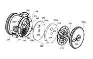
- FIG. 5 is a partially exploded view of the surface cleaning apparatus of FIG. 1 , with a side wheel, seal plate and pre-motor filter exploded;
- FIG. 6 is a side view of the surface cleaning apparatus of FIG. 1 , with a side wheel, cover plate and pre-motor filter removed;
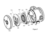
- FIG. 7 is a partially exploded view of the surface cleaning apparatus of FIG. 1 , with a side wheel, cover plate and cord wrap spool exploded;
- FIG. 7 a is the partially exploded view of FIG. 7 , with the cord wrap spool in the cord wrap chamber;
- FIG. 8 is a section taken along line 8 - 8 in FIG. 1 ;
- FIG. 9 is an enlarged view of a portion of FIG. 8 ;
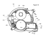
- FIG. 10 is a section taken along line 10 - 10 in FIG. 1 ;
- FIG. 11 is a perspective view of the surface cleaning apparatus of FIG. 1 , with a cyclone bin assembly removed;
- FIG. 12 is a top perspective view of the cyclone bin assembly of FIG. 11 ;
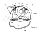
- FIG. 13 is perspective view of the cyclone bin assembly of FIG. 12 , with one end wall open;
- FIG. 14 is perspective view of the cyclone bin assembly of FIG. 13 , with one end wall removed;
- FIG. 15 is a section view taken along line 15 - 15 in FIG. 14 .
- the surface cleaning apparatus 100 is a canister vacuum cleaner.
- the surface cleaning apparatus 100 may be another type of surface cleaning apparatus, including, for example, a hand operable surface cleaning apparatus, an upright vacuum cleaner, a stick vac, a wet-dry vacuum cleaner and a carpet extractor.
- the surface cleaning apparatus 100 has a dirty air inlet 102 , a clean air outlet 104 and an airflow passage extending therebetween.
- the dirty air inlet 102 is the air inlet 234 of an optional suction hose connector 106 that can be connected to the downstream end of a flexible suction hose or other type of cleaning accessory tool, including, for example, a surface cleaning head, a wand and a nozzle. Any standard surface cleaning head may be provided on the upstream end of the flexible hose or wand.
- a hose connector may not be used. Alternately, or in addition, the hose or wand may be connected directly to treatment member 108 .
- the airflow passage extends through an air treatment member 108 that can treat the air in a desired manner, including for example removing dirt particles and debris from the air.
- the air treatment member 108 comprises a cyclone bin assembly 110 .
- the air treatment member 108 can comprise a bag, a filter or other air treating means.
- the air treatment member may be removably mounted to main body 112 or may be fixed in main body 112 .
- the cyclone bin assembly may be of any design or it may use one or more features of the cyclone bin assembly disclosed herein.
- a suction motor 111 ( FIG. 8 ) is preferably mounted within a main body 112 of the surface cleaning apparatus 100 and is in fluid communication with the cyclone bin assembly 110 .
- the body 112 of the surface cleaning apparatus 100 preferably is a rollable, canister-type body that comprises a platform 114 and two opposing sidewalls 116 a , 116 b that cooperate to define a central cavity 118 .
- the surface cleaning apparatus 100 also preferably comprises two main side wheels 120 a , 120 b , rotatably coupled to the sidewalls 116 a and 116 b , respectively.
- the clean air outlet 104 which is in fluid communication with an outlet of the suction motor 111 , is preferably provided in the body 112 .
- the dirty air inlet 102 is preferably located toward the front 122 of the surface cleaning apparatus 100
- the clear air outlet is preferably located toward the rear 124 .
- the body sidewalls 116 a,b are generally circular and cover substantially the entire side faces of the surface cleaning apparatus 100 .
- One main side wheel 120 a , 120 b is coupled to the outer face of each body sidewall 116 a and 116 b , respectively.
- the side wheels 120 a , 120 b may have a larger diameter 126 than the body sidewalls 116 a,b and can completely cover the outer faces of the sidewalls 116 a,b .
- Each side wheel 120 a,b is rotatably supported, e.g., by a corresponding axle mount 128 a , 128 b , which extends from the body sidewalls 116 a and 116 b , respectively.
- the main side wheels 120 a ( FIG. 6) and 120 b ( FIG. 7 ) are rotatable about a primary axis of rotation 130 .
- the primary axis of rotation 130 passes through the cyclone bin assembly 110 (see for example FIG. 8 ).
- At least one of the side wheels 120 a,b can be openable, and preferably detachable from the body 112 .
- both side wheels 120 a and 120 b are detachably coupled to their corresponding axle mounts 128 a and 128 b by axles comprising threaded hub assemblies 132 a and 132 b , respectively, and can be removed from the body 112 .
- Removing the side wheels 120 a , 120 b from the body 112 , or otherwise positioning them in an open configuration, may allow a user to access a variety of components located in compartments between the side wheels 120 a and 120 b and the corresponding sidewalls 116 a and 116 b , as explained in greater detail below.
- FIG. 9 is an enlarged view of hub assembly 132 b , and it is understood that analogous features are provided on hub assembly 132 a and can be referenced herein using the same references numbers having an “a” suffix.
- Hub assembly 132 b provides a rotational mount for wheel 120 b and may be of various designs.
- hub assembly 132 b comprises a threaded socket 134 b and mating threaded lug 136 b .
- the threaded inserts 138 b provide a threaded central bores for receiving the mating threaded shafts 140 b on the lugs 136 b.
- each threaded socket 134 b comprises a threaded insert member 138 b , that is positioned within a corresponding axle mount 128 b , and preferably non-rotatably and non-removably mounted, in axle mount 128 b .
- the threaded insert 138 b may be non-rotatably fastened to the axle mount 128 b , for example by using a screw or other fastener, a sliding locking fit, an adhesive and the like.
- Each lug 136 b comprises a thread shaft 140 b extending from a head 142 b .
- the threaded shaft 140 b has external threads for engaging the threaded bore of the threaded insert 138 b.
- the socket 134 b can comprise integral threads formed on the inner surfaces of the axle mount 128 b .
- the sidewalls may include a bearing or the like.
- the heads 142 a , 142 b are configured to be engaged by a user.
- Each lug 136 a , 136 b is rotatable between a locked and an unlocked position relative to its insert 138 a , 138 b .
- the lugs 136 a , 136 b can be axially inserted and removed from the inserts 138 a , 138 b . Removing the lugs 136 a , 136 b from the inserts 138 a , 138 b can allow a user to remove the side wheels 120 a and 120 b retained by the lugs 136 a and 136 b , respectively.
- a user can position the side wheel 120 a , 120 b over the corresponding sidewall 116 a , 116 b , insert the lugs 136 a , 136 b into the treaded inserts 138 a , 138 b and then rotate the lugs 136 a , 136 b , in a locking direction 144 a ( FIG. 2 ), 144 b ( FIG. 11 ), into the locked position to retain the wheels 120 a , 120 b in their operating position.
- the heads 142 a and 142 b are sized and shaped to be grasped by the bare fingers of a user. Configuring the heads 142 a , 142 b to be grasped by the bare fingers of a user may help facilitate the attachment and release of the lugs 136 a , 136 b from the threaded inserts 138 a , 138 b by hand, without requiring additional tools.
- the heads 136 a , 136 b can be configured to be engaged by a tool, including, for example, a screw driver, socket, allan key and wrench.
- a tool including, for example, a screw driver, socket, allan key and wrench.
- lug 136 b comprises a wheel bearing surface 146 b configured to rotatably support an inner edge 148 b of a corresponding the side wheel 116 b . Allowing rotation between the wheel bearing surface 146 b and the inner edge 148 b of the wheel 120 b facilitates rotation of the side wheel 120 b relative to the body 112 .
- the interface between the wheel bearing surface 146 b and the inner edge 148 b of the side wheel 120 b can be lubricated or otherwise treated to help reduce friction at the interface may be provided.
- a rotary bearing or other type of bearing apparatus may be used to support the side wheels 120 a and 120 b on the hub assemblies 132 a and 132 b .
- the wheel bearing surfaces 146 on the lug portions 132 a , 132 b are identical, and the inner edges 148 of the side wheels 120 a , 120 b are identical. Providing identical wheel bearing surfaces 146 a , 146 b and inner edge surfaces 148 a , 148 b may allows the side wheels 120 a , 120 b to be interchangeable, such that each side wheel 120 a , 120 b can be used on either side of the surface cleaning apparatus 100 .
- the friction between the wheel bearing surface 146 b and the inner edge 148 b of the side wheel 120 b is sufficiently low to allow the side wheel 120 b to rotate relative to the lug 136 b without exerting a significant rotation torque on the lug 132 b .
- the side wheels 120 a , 120 b may exert a rotational torque on the lugs 136 a , 136 b .
- the threads on the lugs 136 a , 136 b and inserts 138 a , 138 b can be configured so that the direction of forward rotation 147 of a side wheel, for example side wheel 120 a in FIG.
- each lug 136 a , 136 b can have a locking direction 144 a , 144 b that coincides with, e.g., the forward direction of rotation of the side wheel 120 a , 120 b .
- the locking direction of lug 144 a is counter-clockwise (as viewed in FIG. 2 )
- the locking direction of lug 144 b is clockwise (as viewed in FIG. 11 ).
- each wheel 120 a , 120 b may comprise a tire 149 a , 149 b extending around the perimeter of the wheel.
- the tires 149 a , 149 b can be formed from a different material than the wheels 120 a , 120 b .
- the tire 149 a , 149 b can be formed from a material that is softer than the wheel material, for example rubber, which may help increase the traction of the wheels 120 a , 120 b.
- the main side wheels 120 a , 120 b are configured to carry a majority of the load of the surface cleaning apparatus 100 , when the surface cleaning apparatus 100 is in use.
- the surface cleaning apparatus 100 may ride solely or primarily on the side wheels 120 a , 120 b when it is being pulled in a forward or backward direction by a user.
- the surface cleaning apparatus 100 can comprise one or more stabilizer wheels, in addition to the side wheels 120 a , 120 b .
- the stabilizer wheels are configured to help support the surface cleaning apparatus 100 in a generally horizontal position as exemplified in FIG. 2 when the surface cleaning apparatus 100 is at rest.
- the stabilizer wheels can be configured to not contact the ground when the body 112 is horizontal, and contact the ground when the body 112 rotates forward, or backward, by a predetermined amount. Configuring the stabilizer wheels in this manner may help prevent the surface cleaning apparatus 100 from over-rotating in a forward or backward direction.
- front and rear stabilizer wheels are provided, then the stabilizer wheels are positioned such that only one will contact a horizontal floor surface at a time.
- the surface cleaning apparatus 100 comprises a front stabilizer wheel 150 and a rear stabilizer wheel 152 .
- the front stabilizer wheel is preferably a cylindrical, roller-type wheel mounted toward the front of the body 112 by a pair of mounting brackets 156 .
- the front stabilizer wheel is rotatable about an axis 154 of rotation that is generally parallel to the primary axis of rotation 130 and is provided forward of the primary axis of rotation 130 .
- the front stabilizer wheel 150 can be located so that the axis of rotation 154 is outside the diameter 126 of the side wheels 120 a , 120 b.
- the front stabilizer wheel 150 When the surface cleaning apparatus 100 is in a horizontal configuration, for example when it is in use, the front stabilizer wheel 150 may be spaced above the floor (see FIG. 2 ). When the surface cleaning apparatus 100 pivots forward, the front stabilizer wheel 150 can contact the ground. With the front stabilizer wheel 150 on the ground, the surface cleaning apparatus 100 is supported in a generally stable rest position by three points of contact (the side wheels 120 a , 120 b and the front stabilizer wheel 150 ).
- the rear stabilizer wheel 152 is a swivelable, caster-type wheel.
- the rear stabilizer wheel 152 may be swivelably mounted in a recess 158 on the underside of a post-motor filter housing 160 (see also FIG. 10 ), which extends from the rear of the body 112 .
- the rear stabilizer wheel 152 is preferably mounted behind the primary axis of rotation 130 .
- the rear stabilizer wheel 152 can be in rolling contact with the ground when the surface cleaning apparatus 100 is in the horizontal position. In this configuration, the rear stabilizer wheel 152 can help support the surface cleaning apparatus 100 when it is in use, and may help limit rearward rotation of the body 112 .
- the front and rear stabilizer wheels 150 , 152 can be configured so that only one of the stabilizer wheels 150 , 152 can contact the ground at any given time when the vacuum cleaner is on a horizontal surface. This prevents both stabilizer wheels 150 , 152 from simultaneously contacting the ground when the vacuum cleaner is used on a horizontal surface. If both stabilizer wheels contact the ground at the same time, this may interfere with the steering of the surface cleaning apparatus 100 . In the example illustrated, the rear stabilizer wheel 152 is lifted out of contact with the ground when the front stabilizer wheel 150 is in contact with the ground, and vice versa.
- cyclone bin assembly 110 includes a cyclone chamber 162 and a dirt collection chamber 164 .
- the cyclone bin assembly 110 is detachably mounted in the cavity 118 , laterally between the sidewalls 116 a , 116 b and side wheels 120 a , 120 b .
- Positioning the cyclone bin assembly 110 in the cavity 118 , between the body sidewalls 116 a , 116 b may help protect the cyclone bin assembly 110 from side impacts, for example if the surface cleaning apparatus 100 contacts a piece of furniture or other obstacle.
- the body sidewalls 116 a , 116 b have a larger cross-sectional area than the cyclone bin assembly 110 . More preferably, the transverse faces of the cyclone bin assembly 110 are entirely covered by the body sidewalls 116 a , 116 b.
- the cyclone chamber 162 is bounded by a sidewall 166 , a first end wall 168 and a second end wall 170 .
- a tangential air inlet 172 is provided in the sidewall of the cyclone chamber 162 and is in fluid communication with the dirty air inlet 102 . Air flowing into the cyclone chamber 162 via the air inlet can circulate around the interior of the cyclone chamber 162 and dirt particles and other debris can become disentrained from the circulating air.
- a slot 180 formed between the sidewall 166 and the second end wall 170 serves as a cyclone dirt outlet 180 ( FIG. 8 ). Debris separated from the air flow in the cyclone chamber 162 can travel from the cyclone chamber 162 , through the dirt outlet 180 to the dirt collection chamber 164 .
- Air can exit the cyclone chamber 162 via an air outlet.
- the cyclone air outlet includes a vortex finder 182 ( FIGS. 8 , 13 ).
- a removable screen 183 can be positioned over the vortex finder 182 .
- the cyclone chamber 162 extends along a longitudinal cyclone axis 184 .
- the longitudinal cyclone axis is aligned with the orientation of the vortex finder 182 and is generally transverse to the direction of movement of the surface cleaning apparatus 100 .
- the cyclone chamber 162 has a generally circular cross sectional shape (taken in a plane perpendicular to the cyclone axis) and has a cyclone diameter 186 .
- the dirt collection chamber 164 comprises a sidewall 174 , a first end wall 176 and an opposing second end wall 178 .
- at least a portion of the dirt collection chamber sidewall 174 is integral with a portion of the cyclone chamber sidewall 166
- at least a portion of the first cyclone end wall 168 is integral with a portion of the first dirt collection chamber end wall 176 .
- a lower surface 188 of the cyclone bin assembly 110 is preferably configured to rest on the platform 114 , and the first and second end walls 168 , 170 of the cyclone bin assembly 110 may be shaped to engage the inner surfaces of the body sidewalls 116 a , 116 b , respectively.
- the upper portion of the cyclone bin assembly 110 (as viewed when installed in the cavity 118 ) can have a radius of curvature that generally corresponds to the radius of curvature of the body sidewalls 116 a , 116 b and the side wheels 120 a , 120 b .
- Matching the curvature of the cyclone bin assembly 110 with the curvature of the side wheels 120 a , 120 b may help facilitate mounting of the cyclone bin assembly 110 within the body 112 , so that the walls of the cyclone bin assembly 110 do not extend radially beyond the body sidewalls 116 a , 116 b or main side wheels 120 a , 120 b.
- the second dirt collection chamber end wall 178 is preferably pivotally connected to the dirt collection chamber sidewall 174 .
- the second dirt collection chamber end wall 178 can be opened to empty dirt and debris from the interior of the dirt collection chamber 164 .
- the cyclone chamber is openable concurrently with the dirt collection chamber.
- the second cyclone end wall 170 is integral with and is openable with the second dirt collection chamber end wall 178 . Opening the second cyclone end wall 170 can allow dirt and debris to be emptied from the cyclone chamber 162 .
- the second dirt collection chamber sidewall 178 can be retained in the closed position by a releasable latch 204 .
- the screen 183 and/or the vortex finder 182 can be removable from the cyclone chamber 162 and can be removed when the second dirt collection chamber end wall 178 is open.
- a releasable bin locking mechanism 190 can be used to secure the cyclone bin assembly 110 within the cavity 118 .
- the bin locking mechanism 190 retains the cyclone bin assembly 110 within the cavity 118 by engaging at least one of the body sidewalls 116 a , 116 b , although the cyclone bin assembly may alternately, or in addition, be secured to the platform 114 .
- the bin locking mechanism 190 comprises a mechanical linkage comprising an actuating lever 192 pivotally connected to the cyclone bin assembly 110 and a pair of locking pins 194 movably connected to the actuating lever 192 .
- a release member 196 that is configured to be engaged by a user, is connected to the actuating lever 192 .
- Corresponding locking cavities 198 for engaging the locking pins 194 are provided in the body sidewalls 116 a , 116 b . In the illustrated example, the locking cavities 198 are shaped to slidingly receive the locking pins 194 .
- Pivoting the actuating lever 192 causes the locking pins 194 to move between a locked position, in which the locking pins 194 extend into the locking cavities 198 , and a retracted position in which the locking pins 194 are free from the locking cavities 198 .
- the bin locking mechanism 190 can include a biasing member, for example spring 200 , for biasing the actuating lever 192 and locking pins 194 toward the locked position. It will be appreciated that a single locking pin 194 may be used. Also, other locking mechanisms may be utilized.
- a handle 202 is provided on the top of the cyclone bin assembly 110 .
- the handle 202 is configured to be grasped by a user.
- the handle 202 can be used to manipulate the surface cleaning apparatus 100 .
- the handle 202 can be used to carry the cyclone bin assembly 110 , for example to position the cyclone bin assembly 110 above a waste receptacle for emptying.
- the handle 202 is connected to the dirt collection chamber sidewall 174 .
- the handle 202 is in close proximity to the release member 196 of the bin locking mechanism 190 . Placing the handle 202 and release member 196 in close proximity may allow a user to release the bin locking mechanism 190 and lift the cyclone bin assembly 110 out of the cavity 118 with a single hand. Accordingly, the actuator (e.g., release member 196 ) for the locking mechanism may be located such that the actuator may be operated simultaneously when a user grasps handle 202 , thereby permitting one handed operation of the bin removal.
- the actuator e.g., release member 196
- the dirt collection chamber sidewall 174 comprises a recess 206 that is shaped to receive a corresponding portion of the body 112 .
- the platform 114 comprises a generally planar bearing surface 208 for supporting the cyclone bin assembly 110 .
- the platform 114 also comprises at least a portion of the suction motor housing 210 surrounding the suction motor 111 .
- the recess 206 in the dirt collection chamber sidewall 174 is shaped to receive the portion of the motor housing 210 projecting above the planar bearing surface 208 .
- At least a portion of the dirt collection chamber 164 surrounds at least a portion of the suction motor 111 and the suction motor housing 210 .
- at least a portion of the dirt collection chamber 164 is positioned between the cyclone chamber 162 and the suction motor housing 210 (and the suction motor 111 therein).
- the shape of the recess 206 is selected to correspond to the shape of the suction motor housing 210 .
- the suction motor housing is shaped to conform with the shape of the suction motor. Accordingly, suction motor housing may have a first portion 210 a that overlies the suction fan and a second portion 210 b that overlies the motor section.
- Configuring the dirt collection chamber 164 to at least partially surround the suction motor housing 210 may help reduce the overall size of the surface cleaning apparatus 100 , and/or may help increase the capacity of the dirt collection chamber 164 .
- the dirt collection chamber 164 may surround at least a portion of the cyclone chamber 162 .
- the dirt collection chamber 164 can include one or more internal diverter walls.
- the diverter walls may help separate the dirt collection chamber 164 into separate dirt collection portions.
- the diverter wall can be positioned opposite the dirt outlet 180 of the cyclone chamber 162 . Providing the diverter wall opposite the dirt outlet 180 may help divide the incoming dirt particles and other debris between the first and second dirt collection portions.
- the dirt collection chamber 164 includes a diverter wall 212 that is positioned opposite the dirt outlet 180 and may extend along substantially the entire height 230 ( FIG. 15 ) of the cyclone chamber 162 .
- diverter all 212 may comprise the portion of the recess that seats on the second portion 210 b of motor housing 210 that overlies the motor section.
- the diverter wall 212 is a curved portion of the dirt collection chamber sidewall 174 , which comprises the inner surface of the recess 206 described above.
- the diverter wall 212 can be a separate member or rib extending from the dirt collection chamber sidewall 174 .
- the diverter wall 212 can be shorter than the cyclone chamber 162 .
- the diverter wall 212 overlies at least a portion of the dirt outlet 180 .
- diverter wall 212 may extend all the way to end wall 176 or may terminate prior thereto and preferably at a location spaced from dirt outlet 180 towards end wall 176 .
- the diverter wall 212 defines a first dirt collection portion 216 on a first side of the diverter wall 212 , and a second dirt collection 218 portion on an opposing second side of the diverter wall 212 .
- the diverter wall 212 does not extend all the way to cyclone sidewall 166 and the first and second dirt collection portions 216 , 218 are not isolated from each other.
- a relatively narrow throttling passage 220 is defined between the diverter wall 212 and the cyclone sidewall 166 .
- dirty air from the cyclone chamber 162 can exit the dirt outlet 180 and flow into the dirt collection chamber 164 , as illustrated using arrows 222 .
- the dirty air flowing through the dirt collection chamber 164 can carry entrained fine dirt particles, and other debris.
- the passage 220 is configured to allow dirty air, containing dirt particles and other debris to move between the first and second dirt collection portions 216 , 218 .
- the dirt outlet 180 is asymmetrically positioned relative to the first and second dirt collection portions 216 , 218 . That is, the dirt outlet 180 is configured so that the centre of the dirt outlet 180 , represented by radially oriented axis 224 , is located within dirt collection portion 216 . In this configuration, the centre of the dirt outlet 180 is not aligned with the diverter wall 212 . Configuring the dirt outlet 180 in this manner may help direct dirty air exiting the dirt outlet 180 toward dirt collection portion 216 . Alternatively, the dirt outlet 180 can be configured so that is symmetrically positioned relative to the dirt collection portions 216 , 218 .
- the air exits the dirt air outlet 180 and enters first portion 216 .
- the air travels to or towards the distal part 216 a and then turns to return through first part 216 towards passage 220 .
- Some of the entrained dirt will be disentrained as the air changes direction in part 216 .
- Passage 220 is preferably narrower than the portion of the dirt chamber upstream thereof. Accordingly, this will cause an increase in the velocity of the air travelling through passage 220 to second portion 218 .
- the velocity of the air, and the fine particles entrained therein may increase.
- the air travels to or towards the distal part 218 a and then turns to return through dirt outlet 180 into the cyclone chamber. Some of the entrained dirt will be disentrained as the air changes direction in part 218 . Further, when the dirty air flow exits the passage 220 and enters the relatively larger volume of dirt collection portion 218 , the velocity of the dirty air may decrease, which may help disentrain the fine dirt particles traveling with the dirty air flow. Accordingly, passage 220 may be used to increase the velocity of the air stream and permit finer dirt to be deposited in second portion 218 . Passing over by the divider wall 212 may also create eddy currents or other types of air flow disruptions, which may also help facilitate fine particle disentrainment. From dirt collection portion 218 , the air can re-enter the cyclone chamber 162 through the dirt outlet 180 and exit via the vortex finder 182 .
- the diverter wall 212 can have another cross-sectional shape including, for example an angled or triangular cross-section and a rectangular cross-section. Any shape which reduces the width of passage 220 may be used (i.e., a portion of the wall facing the dirt outlet extends inwardly towards the dirt outlet 180 ).
- the dirt collection chamber 164 can comprise a secondary divider in a dirt collection portion.
- the secondary divider comprises a secondary divider ridge 226 extending inwardly from the end wall opposite the dirt outlet 180 .
- the secondary divider ridge 226 extends from the second end wall 178 and preferably terminates prior to the first end wall 176 , which also comprises the clean air outlet of the cyclone chamber 162 .
- the secondary divider ridge 226 extends from the cyclone chamber sidewall 174 to the dirt collection chamber sidewall 166 .
- Providing a secondary divider ridge 226 in the dirt collection portion 218 may help direct air flow toward the dirt outlet 180 , as illustrated by arrows 222 .
- the secondary divider ridge 226 may also help create additional eddy currents and/or other flow disruptions that may help facilitate the disentrainment of fine dirt particles from the air flow 222 .
- Directing the air flow toward the dirt outlet 180 may help create a relatively calm region, having relatively low air flow velocity, downstream from the secondary divider ridge 226 towards second end wall 176 , in which fine dirt particles can accumulate.
- Providing a relatively calm region may help reduce re-entrainment of the fine particles that settle in the calm region into the air flow re-entering the dirt outlet 180 .
- divider wall 226 may create a wind shield thereby inhibiting the reentrainment of fine dirt that has settled in second portion 218 .
- the height 228 of the secondary diverting ridge (the distance it extends inwardly from lower surface 188 ) can be between about 5% and about 95% of the height 230 of the cyclone chamber 162 .
- the height 228 of the secondary diverting ridge 226 is less than about 66% of the height of the cyclone 230 , and more preferably is approximately 30% of the cyclone height 230 .
- the secondary dividing ridge 226 does not extend into the dirt outlet 180 .
- the secondary diverting ridge 226 comprises a portion of sidewall 232 of the tangential air inlet 172 .
- the secondary diverting ridge 226 can be a separate member extending from the second end wall 178 , and need not comprise the tangential air inlet 172 .
- the secondary diverting ridge 226 can have any other suitable cross-sectional shape, including, for example a triangular cross-section and a rectangular cross-section.
- the diverter wall 212 , secondary dividing ridge 226 and dirt outlet 180 alignment features described above can also be used, individually or in combination, in a vertically oriented cyclone bin assembly 110 .
- the suction hose connector 106 is connected to the body 112 , and remains connected to the body 112 when the cyclone bin assembly 110 is removed.
- the suction hose connector 106 comprises an air inlet 234 that is connectable to the suction hose, and an opposing air outlet 236 .
- a throat portion 238 of the suction hose connector 106 extends between the air inlet 234 and air outlet 236 . Coupling the suction hose connector 106 to the body 112 may help facilitate the removal of the cyclone bin assembly 110 (for example to empty the dirt collection chamber 164 ) while leaving a suction hose connected to the body 112 , via the suction hose connector 106 .
- the air outlet 236 is configured to connect to the tangential air inlet 172 of the cyclone chamber 162 .
- a sealing face 240 on the tangential air inlet 172 is shaped to match the shape of the air outlet 236 of the suction hose connector 106 .
- a gasket, or other type of sealing member can be provided at the interface between the sealing face 240 and the air outlet 236 .
- the air outlet 236 of the suction hose connector 106 and the sealing face 240 of the tangential air inlet 172 are configured so that the sealing face 240 can slide relative to the air outlet 236 (vertically in the illustrated example) as the cyclone bin assembly 110 is being placed on, or lifted off of the platform 114 . Lowering the cyclone bin assembly 110 onto the platform 114 can slide the sealing face 240 into a sealing position relative to the air outlet 236 .
- the sealing face 240 (and preferably part or all of the hose connector) is recessed within the cyclone bin assembly 110 .
- the cyclone bin assembly 110 includes a notch 242 configured to receive the throat portion of the suction hose connector 106 when the cyclone bin assembly 110 is placed on the platform. With the cyclone bin assembly 110 on the platform, at least a portion of the throat 238 and the air outlet 236 are nested within cyclone bin assembly 110 . Nesting at least a portion of the suction hose connector 106 within the cyclone bin assembly 110 may also help reduce the overall length of the surface cleaning apparatus 100 .
- the suction hose connector 106 can serve as an alignment member to help guide the cyclone bin assembly 110 into a desired orientation when bin assembly 110 is remounted on platform 114 .
- the suction hose connector 106 may be fixedly connected to the cyclone bin assembly 110 , and may be removable with the cyclone bin assembly 110 .
- an electrical power connector 244 is provided adjacent the suction hose connector 106 .
- the electrical power connector 244 can be configured to receive a mating power coupling and may provide power to a cleaning tool, including, for example a surface cleaning head with a powered rotating brush.
- air exiting the cyclone chamber 162 flows to a suction motor inlet 246 via a filter chamber 248 .
- the filter chamber 248 is provided downstream from the cyclone air outlet.
- the filter chamber 248 comprises a recessed chamber in the body sidewall 116 a that is enclosed by an seal plate 250 , that is preferably openable.
- a sealing gasket 254 or other means of creating an air tight compartment is preferably provided at the interface between an annular rim 252 of the sidewall 116 a and the seal plate 250 to help provide an air-tight filter chamber 248 .
- the filter chamber 248 extends over substantially the entire sidewall 116 a and overlies substantially all of the transverse cross sectional area of cyclone chamber 162 , dirt collection chamber 164 and suction motor 111 .
- a pre-motor filter 256 is provided in the filter chamber 248 to filter the air before it enters the suction motor inlet.
- the pre-motor filter 256 is sized to cover substantially the entire transverse area of the filter chamber 248 , and overlie substantially all of the transverse cross sectional area of the cyclone chamber 162 , dirt collection chamber 164 and suction motor 111 .
- the pre-motor filter 256 comprises first and second pre-motor filters 256 a , 256 b .
- the filter chamber 248 comprises an air inlet chamber 258 on the upstream side 272 of the pre-motor filter 256 , and an air outlet chamber 260 on the opposing downstream side of the pre-motor filter 256 . Air can travel from the air inlet chamber 258 to the air outlet chamber 260 by flowing through the pre-motor filter 256 .
- the upstream side of the pre-motor filter is the outward facing face of the pre-motor filter.
- the air inlet chamber 258 may be fluidly connected to the vortex finder 182 by an inlet conduit 262 that extends through a first aperture 264 in the pre-motor filter 256 .
- the air outlet chamber 260 is in fluid communication with the inlet 246 of the suction motor 111 .
- the pre-motor filter 256 may be supported by a plurality of support ribs 266 extending from the sidewall 116 a into the air outlet chamber 260 . Cutouts can be provided in the ribs 266 to allow air to circulate within the air outlet chamber 266 and flow toward the suction motor inlet 246 .
- the axle mount 128 a for supporting the side wheel 120 a is provided on the main body 12 and accordingly extends through the air filter chamber 248 , a second aperture 268 in the pre-motor filter 256 and through an axle mount aperture 270 in the seal plate 250 ( FIG. 5 ).
- the axle mount aperture 270 in the seal plate 250 is configured to provide an air-tight seal against the axle mount 128 a .
- a sealing gasket or the like can be provided at the interface between the seal plate 250 and the axle mount 128 a .
- the pre-motor filter 256 surrounds the axle mount 128 a.
- the seal plate 250 is removable, when the side wheel 120 a is moved to an open position or detached, to allow a user to access the pre-motor filter 256 .
- the seal plate 250 can be movably attached to the body 112 , for example pivotally connected to the sidewall 116 a , such that the seal plate 250 can be opened without being completely detached from the body 112 .
- the seal plate 250 is transparent, or at least partially transparent. Providing a transparent seal plate 250 may help facilitate visual inspection of the upstream side 272 of the pre-motor filter 256 while the seal plate 250 is in place. When the seal plate 250 is removed, the pre-motor filter 256 may be removed, for example for cleaning or replacement.
- a portion of the suction motor housing 210 can be removably connected to the body 112 .
- the removable portion 274 of the suction motor housing 210 comprises the suction motor air inlet 246 .
- the removable portion 274 of the suction motor housing is large enough to allow access to and/or removal of the suction motor 111 from the body 112 .
- the removable portion 274 of the suction motor housing 210 , and optionally the suction motor 111 are accessible through the air filter chamber 248 and can be accessed when the seal plate 250 and pre-motor filter 256 are removed.
- Removable portion 274 may comprise an air intake grill and may be secured to the main body 12 by any means, such as screws or the like.
- a bleed valve 276 is optionally provided to supply clean air to the suction motor inlet.
- a bleed valve air outlet 278 is in fluid communication with the air outlet chamber 260 and can introduce clean air into the air outlet chamber 260 downstream from the pre-motor filter 256 . Air introduced by the bleed valve 276 can flow through the optional cutouts in the supporting ribs 266 , as described above.
- the bleed valve 276 may be a pressure sensitive valve that is opened when there is a blockage in the air flow path upstream from the suction motor 111 . In the illustrated example, the bleed valve 276 is parallel with the suction motor 111 .
- a bleed valve inlet 280 is provided toward the front of the body 112 .
- the side wheel 120 a covering the seal plate 250 includes at least one transparent region 282 .
- Providing a transparent region 282 in the side wheel 120 a may allow a user to visually inspect the upstream side 272 pre-motor filter 256 while the side wheel 120 a is in place.
- the side wheel 120 a includes a transparent window 282 .
- the transparent window 282 can be sized so that a user can view a desired amount of the pre-motor filter 256 through the window.
- the window 282 is oriented in a generally radial orientation, and extends from the hub 132 a to the peripheral edge of the side wheel 120 a .
- Providing a radially oriented window 282 may allow a user to inspect a relatively large portion of the surface of the pre-motor filter 256 when the side wheel 120 a is rotated relative to the body 112 .
- the window 282 can be configured in an annular configuration (optionally concentrically aligned with the side wheel 120 a ) or other suitable configuration.
- the side wheel 120 a can include more than one window 282 .
- a filter chamber 248 may be provided alternately, or in addition, for a post motor filter.
- the air is drawn through the suction motor 111 and ejected via a suction motor outlet 284 and into a post-motor filter chamber 286 , within the post-motor filter housing 160 .
- the post-motor filter chamber 248 contains an air inlet chamber 288 and an optional post-motor filter 290 , including, for example a HEPA filter.
- the post-motor filter chamber 286 also comprises the clean air outlet 104 , on the downstream side of the post-motor filter 290 .
- a grill 292 can be used to cover the clear air outlet 104 .
- the post-motor filter chamber 286 can extend into the body 112 of the surface cleaning apparatus 100 .
- a portion of post-motor filter chamber 286 is positioned transversely between the body sidewalls 116 a , 116 b and the side wheels 120 a , 120 b .
- at least a portion of the post-motor filter 290 is positioned between the sidewalls 116 a , 116 b and within the diameter 126 of the side wheels 120 a , 120 b .
- Configuring the post-motor filter chamber 286 to extend between the sidewalls 116 a , 116 b and inside the diameter 126 of side wheels 120 a , 120 b may help reduce the overall length of the surface cleaning apparatus 100 , as opposed to providing the entirety of the post-motor filter chamber 286 outside the diameter 126 of the side wheels 120 a , 120 b.
- an exposed upper wall 294 of the post-motor filter housing 160 has a smaller surface area than the opposing lower wall 296 .
- the lower wall 296 or the end wall 300 may be openable to allow access to the post-motor filter 290 , for example for inspection and replacement.
- the lower wall 296 is detachable from the post-motor filter housing sidewall 298 to allow access to the post-motor filter 290 .
- a sealing gasket can be provided at the interface between the lower wall and the sidewall to help seal the post-motor filter chamber 248 .
- Providing a removable lower wall 296 or end wall 300 may help facilitate removal of a post-motor filter 290 that has a larger area than the exposed upper wall 294 , particularly if the post-motor filter 290 is rigid (for example a HEPA filter cartridge).
- the lower wall 296 can include an openable door to allow access to the post-motor filter 290 .
- the upper wall 194 , sidewall 298 and/or end wall 300 of the post-motor filter housing can be openable to allow access to the post-motor filter 290 .
- the post-motor filter housing 160 is positioned at the rear of the surface cleaning apparatus 100 .
- the post-motor filter housing 160 can be positioned toward the front of the surface cleaning apparatus 100 , or at another suitable location on the body 112 .
- the surface cleaning apparatus 100 can comprise an internal electrical cord winding apparatus.
- the electrical cord winding apparatus is preferably a powered cord winder apparatus that includes a cord wrap spool 302 and a cord wrap motor 304 .
- An electrical cord that is wrapped around the spool 302 can be drawn through a cord aperture 306 in the body 112 ( FIG. 10 ).
- the cord aperture 306 can include rollers or other guide members to help guide the cord through the aperture 306 .
- the cord wrap spool 302 is rotatably received in a cord wrap chamber 308 ( FIG. 7 a ).
- the cord wrap chamber 308 comprises a recess in the sidewall 116 b .
- a cover plate 310 can be connected to the sidewall 116 b to enclose the cord wrap chamber 308 , and contain the cord wrap spool 302 .
- the cover plate 310 may be openable, and is preferably removable to allow a user to access the cord wrap chamber 308 .
- the cord wrap spool 302 is rotatable about axle mount 128 b , and has a spool axis of rotation 312 that is coincident with the primary axis of rotation 130 .
- the cord wrap spool 302 comprises a mounting collar 314 that is non-rotatably connected to the axle mount 128 b .
- an inward bearing surface 316 on the spool 302 is slidably supported on a complementary collar bearing surface 318 to allow rotation of the spool 302 relative to the body 112 .
- a roller bearing, ball bearing or other type of bearing apparatus can be provided between the spool 302 and the axle mount 128 b.
- Operation of the cord wrap motor 304 can be controlled by an onboard controller 320 that is triggered by a cord wrap switch 322 (see also FIG. 6 ).
- Power for the cord wrap motor 304 can be provided by an onboard power source 324 .
- Providing an onboard power source 324 enables the cord wrap spool 302 to be driven to wind the electrical cord even after the electrical cord has been unplugged from the wall socket.
- the onboard power source 324 can be any type of portable power source, including, for example, one or more batteries contained in a battery compartment 326 .
- the batteries can be rechargeable and may be recharged when the electrical cord is plugged in.
- the controller 320 and onboard power source 324 are located in an accessory chamber 328 defined between the outer surface of the cover plate 310 and the side wheel 120 b .
- the controller 320 and onboard power source 324 are connected to the outer surface of the cover plate 210 .
- the cord wrap spool 302 comprises an inner flange 330 and an outer flange 332 to help retain the electrical cord wrapped on the spool 302 .
- the inner surfaces of the flanges 330 , 332 are separated by a spool width 334 .
- the spool width 334 is selected so that it is not an even multiple of the diameter of the electrical cord, for example a standard 4.5 millimeter diameter electrical cord that is to be wrapped on the spool 302 .
- a spool width 334 that is not an even multiple of the electrical cord diameter, for example setting the spool width to approximately 12 millimeters, may help reduce binding or jamming of the electrical cord as it is wound, or unwound from the spool 302 .
- the spool width is between 10% and 90% of the length of the number of widths of the electrical cord that may fit across the spool, and preferably between 20 and 80%.
- the peripheral edge of the inner flange 330 comprises a plurality of gear teeth 336 .
- the teeth 336 on the perimeter of the inner flange 330 are configured to mesh with the teeth on a drive sprocket 338 that is coupled to the cord wrap motor 304 .
- rotation of the sprocket 338 of the cord wrap motor 304 can cause rotation of the spool 302 .
- the spool 302 can be connected to the cord wrap motor 304 using another drive train apparatus, including, for example, a belt drive and a gear train.
- the cord wrap motor 304 can include a clutch or other disengagement member to decouple the rotation of the spool 302 and the motor when desired, for example when the electrical cord is being unwound from the spool 302 .
- the cord wrap motor 304 can remain drivingly connected to the spool 302 and may be driven in reverse when a user pulls the cord from the spool 302 .
- the controller 320 can include a protection module to help prevent electrical current generated by the rotating motor from damaging or overloading the controller 320 .
- the cord wrap switch 322 can be any type of electrical switch, or other type of actuator, accessible to the user of the surface cleaning apparatus 100 .
- the cord wrap switch comprises a cord wrap pedal 322 that is electrically connected to the controller 320 .
- the cord wrap pedal 322 is preferably pivotally mounted to the rear end of the post-motor filter housing 160 , and can pivot between an “off” position and an “on” position. When the cord wrap pedal 322 is pivoted to the on position, the cord wrap motor 304 is activated and the electrical cord can be wound around the spool 302 .
- the cord wrap pedal 322 is biased toward the off position. Biasing the pedal 322 toward the off position may help prevent the cord wrap switch being inadvertently activated when the surface cleaning apparatus 100 is in use.
- the cord wrap switch can be a button, lever or other type of actuator.
- the cord wrap switch can be configured to be engaged by the hands of a user, instead or, or in addition to, being configured to engage a user's foot.
- the controller 320 can be configured to operate the cord wrap motor 304 at a generally constant wrap speed.
- the wrap speed can be selected so that the velocity of the tip of the electrical cord is maintained below a predetermined threshold as the cord is wrapped around the spool 302 .
- the cord wrap motor 304 can be configured to rotate at about 100 rpm, which may help limit the velocity at the tip of the cord to between about 5 meters per second and about 0.5 meters per second, and may allow the electrical cord to be wound in between about 5 seconds and about 30 seconds.
- the controller 320 can be configured to disengage or deactivate the cord wrap motor 304 if the cord wrap spool 302 becomes jammed or otherwise stops rotating, even while the cord wrap pedal 322 is depressed.
- the controller 320 is configured to monitor the electrical current drawn by the cord wrap motor 304 . If the spool 302 stops rotating, the sprocket 338 will stop rotating and the current drawn by the cord wrap motor 304 may increase. In response to such a current increase, the controller 320 can reduce or eliminate the power supplied to the cord wrap motor 304 . Reducing the power supplied to a non-rotating motor may help reduce motor burn out.
- the controller 320 can be configured to monitor rotation of the spool 302 , comprise an end stop sensor or switch, or monitor other suitable factors to help determine when the spool 302 has stopped rotating.
- the cord wrap motor 304 can operate continuously while the user depresses the cord wrap pedal 322 .
- Providing a continuous, sustained wrapping motion may help facilitate the wrapping of relatively long electrical cords, for example cords in excess of 5.5 meters feet, around the spool 302 .
- known spring biased cord winding spools may not be able to provide the sustained wrapping motion to wrap long cords.
- a manual drive mechanism can be provided to help wind the cord wrap spool 302 if the onboard power source is depleted.
- a hand crank or other type of manual actuator can be connected to the spool 302 to enable a user to manually wind in the electrical cord.
- any one or more of the features disclosed herein may be used in any particular combination or sub-combination, including, without limitation, the cord spool, the protective sidewalls, the cyclone bin assembly lock, an openable or removable wheel to access a component of the surface cleaning apparatus, the positioning and/or configuration of the post motor filter housing, the use of one or more stabilizer wheels, the seal plate, the pre-motor filter window in a wheel, the openable suction motor housing, the wheel axle extending through the filter, The divided dirt collection chamber with the diverter, the asymmetrical orientation of the dirt outlet 180 , the threaded wheels, the passage 220 for the divided dirt collection chamber, the side wheels and positioning an operating component in a sidewall of the main body 112 .
Abstract
Description
Claims (26)
Priority Applications (2)
| Application Number | Priority Date | Filing Date | Title |
|---|---|---|---|
| US13/039,643 US8739357B2 (en) | 2011-03-03 | 2011-03-03 | Filter construction for a surface cleaning apparatus |
| PCT/CA2012/000184 WO2012116436A1 (en) | 2011-03-03 | 2012-03-02 | Surface cleaning apparatus |
Applications Claiming Priority (1)
| Application Number | Priority Date | Filing Date | Title |
|---|---|---|---|
| US13/039,643 US8739357B2 (en) | 2011-03-03 | 2011-03-03 | Filter construction for a surface cleaning apparatus |
Publications (2)
| Publication Number | Publication Date |
|---|---|
| US20120222241A1 US20120222241A1 (en) | 2012-09-06 |
| US8739357B2 true US8739357B2 (en) | 2014-06-03 |
Family
ID=46752339
Family Applications (1)
| Application Number | Title | Priority Date | Filing Date |
|---|---|---|---|
| US13/039,643 Active 2032-05-10 US8739357B2 (en) | 2011-03-03 | 2011-03-03 | Filter construction for a surface cleaning apparatus |
Country Status (1)
| Country | Link |
|---|---|
| US (1) | US8739357B2 (en) |
Cited By (7)
| Publication number | Priority date | Publication date | Assignee | Title |
|---|---|---|---|---|
| CN104034147A (en) * | 2014-06-22 | 2014-09-10 | 浙江省新昌县澄潭茶厂 | Disc-type tea tedding ground cleaning machine |
| US9693665B2 (en) | 2014-10-22 | 2017-07-04 | Techtronic Industries Co. Ltd. | Vacuum cleaner having cyclonic separator |
| US9775483B2 (en) | 2014-10-22 | 2017-10-03 | Techtronic Industries Co. Ltd. | Vacuum cleaner having cyclonic separator |
| US10117551B2 (en) | 2014-10-22 | 2018-11-06 | Techtronic Industries Co. Ltd. | Handheld vacuum cleaner |
| US10631697B2 (en) | 2014-02-14 | 2020-04-28 | Techtronic Industries Co. Ltd. | Separator configuration |
| US20210121814A1 (en) * | 2019-10-23 | 2021-04-29 | RVT Group Limited | Dust extraction unit |
| US11382475B2 (en) | 2017-06-19 | 2022-07-12 | Tti (Macao Commercial Offshore) Limited | Surface cleaning apparatus |
Families Citing this family (2)
| Publication number | Priority date | Publication date | Assignee | Title |
|---|---|---|---|---|
| GB2519968A (en) * | 2013-11-01 | 2015-05-13 | Techtronic Floor Care Tech Ltd | Surface cleaning Apparatus |
| US10278557B2 (en) | 2014-04-04 | 2019-05-07 | Techtronic Industries Co. Ltd. | Vacuum cleaner |
Citations (123)
| Publication number | Priority date | Publication date | Assignee | Title |
|---|---|---|---|---|
| US1613250A (en) | 1922-09-29 | 1927-01-04 | Domestic Electric Company | Vacuum cleaner |
| US1856133A (en) * | 1925-05-07 | 1932-05-03 | Apex Electrical Mfg Co | Suction cleaner |
| US2064587A (en) | 1933-07-08 | 1936-12-15 | Electrolux Corp | Vacuum cleaner |
| US2135036A (en) | 1935-11-08 | 1938-11-01 | Electrolux Corp | Vacuum cleaner |
| US2224202A (en) | 1937-06-05 | 1940-12-10 | Hoover Co | Suction cleaner |
| US2280269A (en) | 1938-04-11 | 1942-04-21 | Birtman Electric Co | Suction cleaner |
| US2533057A (en) | 1948-02-18 | 1950-12-05 | Edgar P Senne | Filter replacement construction for vacuum cleaners |
| US2550384A (en) | 1948-12-27 | 1951-04-24 | Edgar P Senne | Air intake mechanism for air filter machines |
| US2621756A (en) * | 1948-02-18 | 1952-12-16 | Electrolux Corp | Filter replacement mechanism for vacuum cleaners |
| US2632524A (en) * | 1946-10-10 | 1953-03-24 | Edgar P Senne | Roller mounted vacuum cleaner for propulsion by flexible hose |
| US2716465A (en) * | 1954-03-26 | 1955-08-30 | Lewyt Corp | Vacuum cleaner assembly |
| US2769996A (en) * | 1953-12-21 | 1956-11-13 | Gen Electric | Mobile vacuum cleaner having a hose adapted to be used as a pushing or pulling means therefor |
| US2811737A (en) | 1954-05-06 | 1957-11-05 | Gen Electric | Mobile electric vacuum cleaner |
| US2918693A (en) * | 1957-10-30 | 1959-12-29 | Westinghouse Electric Corp | Suction cleaning apparatus |
| US3015122A (en) * | 1961-01-04 | 1962-01-02 | Robert E Cook | Mobile electric vacuum cleaner |
| US3085221A (en) | 1960-09-27 | 1963-04-09 | Cannon Electric Co | Connector with selectivity key |
| US3457744A (en) | 1967-12-04 | 1969-07-29 | Southco | Latch fastener |
| US3870486A (en) | 1972-09-22 | 1975-03-11 | Electrolux Ab | Floor surface treating apparatus |
| US3886616A (en) | 1972-12-06 | 1975-06-03 | Fay A Hayes | Hand propelled swimming pool cleaner |
| US5144716A (en) | 1988-10-07 | 1992-09-08 | Hitachi, Ltd. | Electric cleaner, method for producing same and mount base and bumper for electric cleaner |
| US5254019A (en) | 1992-07-08 | 1993-10-19 | Burndy Corporation | Configurable coded electrical plug and socket |
| US5268845A (en) | 1991-02-14 | 1993-12-07 | Dell Corporate Services Corp. | Method for detecting low battery state without precise calibration |
| US5297311A (en) | 1992-05-04 | 1994-03-29 | Citywide Machine Wholesale, Inc. | Vacuum cleaner |
| US5402059A (en) | 1994-02-08 | 1995-03-28 | Ford Motor Company | Switching power supply operating at little or no load |
| US5694029A (en) | 1996-01-02 | 1997-12-02 | Dell Usa, L.P. | Digital measurement of switching regulator current |
| US5742153A (en) | 1992-08-18 | 1998-04-21 | Basic Measuring Instruments | Coasting power supply for AC power system waveform measuring instrument |
| US5798633A (en) | 1996-07-26 | 1998-08-25 | General Electric Company | Battery energy storage power conditioning system |
| US5831420A (en) | 1997-04-28 | 1998-11-03 | Motorola, Inc. | Pulse load averaging power converter |
| US6031357A (en) | 1998-04-28 | 2000-02-29 | Mitsumi Electric Co., Ltd. | Battery charge control circuit |
| US6081104A (en) | 1998-11-20 | 2000-06-27 | Applied Power Corporation | Method and apparatus for providing energy to a lighting system |
| US6080022A (en) | 1996-06-28 | 2000-06-27 | Intel Corporation | Multivoltage keyed electrical connector |
| US6141822A (en) | 1996-09-26 | 2000-11-07 | Certech SA, Societe Anonyme | Vacuum cleaner for household refuse |
| US6256832B1 (en) | 1997-01-30 | 2001-07-10 | Notetry Limited | Vacuum cleaner |
| US6307358B1 (en) | 1999-10-15 | 2001-10-23 | Omachron Technologies, Inc. | Method and apparatus for delivering power to a mechanical or electrical system |
| US20010048295A1 (en) | 2000-04-08 | 2001-12-06 | Christoph Joch | Power supply device |
| US6345411B1 (en) | 1998-07-06 | 2002-02-12 | Matsushita Electric Industrial Co., Ltd. | Vacuum cleaner |
| US20020073663A1 (en) | 2000-01-14 | 2002-06-20 | White Consolidated Industries, Inc. | Bagless dustcup |
| US6425931B1 (en) | 1998-03-27 | 2002-07-30 | Notetry Limited | Cyclonic separation apparatus |
| US20020178701A1 (en) | 2001-05-31 | 2002-12-05 | Jang-Keun Oh | Cyclone dust collecting apparatus for a vacuum cleaner |
| JP2002355198A (en) | 2001-09-20 | 2002-12-10 | Hitachi Ltd | Vacuum cleaner |
| US6532620B2 (en) | 2000-10-19 | 2003-03-18 | Samsung Kwangju Electronics Co., Ltd. | Cyclone dust collecting chamber for a vacuum cleaner |
| US6536073B2 (en) * | 2000-03-01 | 2003-03-25 | Matsushita Electric Industrial Co., Ltd. | Electric vacuum cleaner |
| US20030106182A1 (en) | 2001-12-12 | 2003-06-12 | Lee Yong-Hee | Cyclone dust collecting apparatus for use in vacuum cleaner |
| US20030140444A1 (en) | 2001-12-27 | 2003-07-31 | Matsushita Electric Industrial Co., Ltd. | Vacuum cleaner having an ion generator |
| US6613129B2 (en) | 2001-06-22 | 2003-09-02 | Euro-Pro Corporation | Cyclone and dust filter vacuum cleaner |
| US20030173940A1 (en) | 2002-03-12 | 2003-09-18 | S-B Power Tool Company | DC to DC voltage converter |
| US20030200622A1 (en) | 2000-06-16 | 2003-10-30 | Kyu-Chang Park | Upright-type vacuum cleaner having a cyclone dust collecting apparatus |
| WO2004008932A1 (en) | 2002-07-20 | 2004-01-29 | Hoover Limited | Cyclonic vacuum cleaner |
| US20040051510A1 (en) | 2002-07-12 | 2004-03-18 | Stefano Saggini | Digital controller for DC-DC switching converters |
| US20040095118A1 (en) | 2002-11-14 | 2004-05-20 | Fyre Storm, Inc. | Power converter circuitry and method |
| WO2004041054A1 (en) | 2002-11-06 | 2004-05-21 | Polar Light Limited | Battery-powered vacuum cleaner |
| US20040163201A1 (en) | 2000-09-01 | 2004-08-26 | Royal Appliance Mfg. Co. | Bagless canister vacuum cleaner |
| US20040216266A1 (en) | 2002-11-06 | 2004-11-04 | Wayne Conrad | Construction of a vacuum cleaner |
| US6902596B2 (en) | 1999-01-08 | 2005-06-07 | Gbd Corporation | Air flow passage for a vacuum cleaner |
| US6929516B2 (en) | 2003-10-28 | 2005-08-16 | 9090-3493 Québec Inc. | Bathing unit controller and connector system therefore |
| US6976885B2 (en) | 2004-03-02 | 2005-12-20 | Mobility Electronics, Inc. | Keyed universal power tip and power source connectors |
| US20060016043A1 (en) | 2004-07-26 | 2006-01-26 | Sanyo Electric Co., Ltd. | Electric vacuum cleaner and cyclonic dust collecting apparatus |
| US20060080947A1 (en) | 2004-10-14 | 2006-04-20 | Samsung Gwangju Electronics Co., Ltd. | Cyclone dust-separating apparatus |
| US20060101610A1 (en) * | 2004-11-16 | 2006-05-18 | Samsung Gwangju Electronics Co., Ltd. | Vacuum cleaner having a cyclone dust collecting apparatus |
| EP1674009A2 (en) | 2004-12-27 | 2006-06-28 | LG Electronics Inc. | Vacuum cleaner |
| US20060156509A1 (en) | 2005-01-18 | 2006-07-20 | Luebbering Gregory W | Vacuum cleaner with collapsible handle |
| US20060213023A1 (en) * | 2003-05-27 | 2006-09-28 | Dyson Technology Limited | Cleaning appliance |
| US7162770B2 (en) | 2003-11-26 | 2007-01-16 | Electrolux Home Care Products Ltd. | Dust separation system |
| US20070067945A1 (en) | 2005-09-23 | 2007-03-29 | Bissell Homecare, Inc. | Vacuum cleaner with two stage filtration |
| US7198656B2 (en) | 2002-10-31 | 2007-04-03 | Toshiba Tec Kabushiki Kaisha | Vacuum cleaner |
| US20070077810A1 (en) | 2005-10-05 | 2007-04-05 | Gogel Nathan A | Floor care appliance equipped with detachable power cord |
| US20070079585A1 (en) | 2005-10-11 | 2007-04-12 | Samsung Gwangju Electronics Co., Ltd. | Multi cyclone dust collector for a vacuum cleaner |
| US20070151072A1 (en) * | 2005-12-30 | 2007-07-05 | Samsung Electronics Co., Ltd. | Vacuum cleaner |
| US20070200540A1 (en) | 2004-07-14 | 2007-08-30 | Rohm Co., Ltd. | Power Source Device |
| US20070226947A1 (en) | 2006-03-29 | 2007-10-04 | Daewoo Electronics Corporation | Vacuum cleaner with an integrated handheld vacuum cleaner unit |
| US20070251048A1 (en) | 2006-04-27 | 2007-11-01 | Daewoo Electronics Corporation | Vacuum cleaner |
| US7291193B2 (en) | 2004-08-23 | 2007-11-06 | Samsung Gwangju Electronics Co., Ltd. | Cyclone dust collector and vacuum cleaner therewith |
| US20070256272A1 (en) | 2005-12-10 | 2007-11-08 | Jae Kyum Kim | Vacuum cleaner |
| WO2007136675A2 (en) | 2006-05-18 | 2007-11-29 | Royal Appliance Mfg. Co. | Single stage cyclone vacuum cleaner |
| US20070289266A1 (en) | 2006-06-16 | 2007-12-20 | Samsung Gwangju Electronics Co., Ltd. | Dust collecting apparatus for vacuum cleaner |
| US20070289264A1 (en) | 2006-06-16 | 2007-12-20 | Samsung Gwangju Electronics Co., Ltd. | Dust collecting apparatus for vacuum cleaner |
| US20080134460A1 (en) | 2006-12-12 | 2008-06-12 | Gbd Corporation | Surface cleaning apparatus |
| WO2008070962A1 (en) | 2006-12-12 | 2008-06-19 | Gbd Corp. | Surface cleaning apparatus |
| WO2008070965A1 (en) | 2006-12-15 | 2008-06-19 | Gbd Corp. | Cyclonic array such as for a vacuum cleaner |
| US20080172992A1 (en) | 2006-12-15 | 2008-07-24 | G.B.D. Corp. | Vacuum cleaner with openable lid |
| US20080172821A1 (en) * | 2006-11-03 | 2008-07-24 | Daewoo Electronics Corporation | Vacuum cleaner |
| US20080178416A1 (en) | 2006-12-12 | 2008-07-31 | G.B.D. Corp. | Surface cleaning apparatus with shoulder strap reel |
| US20080191675A1 (en) | 2006-11-27 | 2008-08-14 | Besser David A | Power extractor detecting power and voltage changes |
| US20080196198A1 (en) | 2007-02-16 | 2008-08-21 | Mytee Products, Inc. | Carpet and floor vacuuming device with improved suction head |
| US20080196196A1 (en) * | 2006-12-15 | 2008-08-21 | G.B.D. Corp. | Vacuum cleaner with wheeled base |
| US20080196194A1 (en) | 2006-12-12 | 2008-08-21 | G.B.D. Corp. | Surface cleaning apparatus with off-centre dirt bin inlet |
| US20080216282A1 (en) | 2007-03-09 | 2008-09-11 | G.B.D. Corp. | Surface cleaning apparatus with enlarged dirt collection chamber |
| US7425225B2 (en) | 2002-02-11 | 2008-09-16 | Dyson Technology Limited | Exhaust assembly |
| US20090000054A1 (en) | 2007-06-29 | 2009-01-01 | Leonard Hampton | Vacuum Cleaner Cleanout System |
| WO2009026709A1 (en) | 2007-08-29 | 2009-03-05 | Gbd Corp. | Cyclonic surface cleaning apparatus with externally positioned dirt chamber |
| US20090106932A1 (en) | 2007-10-25 | 2009-04-30 | Dyson Technology Limited | Cleaning appliance |
| US7547337B2 (en) | 2005-03-29 | 2009-06-16 | Samsung Gwangju Electronics Co., Ltd. | Multi dust-collecting apparatus |
| US20090205160A1 (en) | 2007-12-19 | 2009-08-20 | Wayne Ernest Conrad | Configuration of a cyclone assembly and surface cleaning apparatus having same |
| US20090205298A1 (en) | 2005-08-17 | 2009-08-20 | Lg Electronics Inc. | Dust collecting device for vacuum cleaner |
| US7581286B2 (en) | 2004-12-08 | 2009-09-01 | Lg Electronics Inc. | Vacuum cleaner and dust collection unit thereof |
| USD600416S1 (en) | 2008-04-10 | 2009-09-15 | Lg Electronics Inc. | Vacuum cleaner |
| US20090241286A1 (en) | 2005-12-10 | 2009-10-01 | Man Tae Hwang | Vacuum cleaner |
| US20090266382A1 (en) | 2005-12-10 | 2009-10-29 | Man Tae Hwang | Vacuum cleaner and method of controlling the same |
| US20090300873A1 (en) | 2005-04-08 | 2009-12-10 | Nicholas Gerald Grey | Surface Cleaning Apparatus |
| US20100043170A1 (en) | 2007-03-08 | 2010-02-25 | Kingclean Electric Co., Ltd. | Dust separating device of a cleaner |
| US20100083833A1 (en) | 2008-10-08 | 2010-04-08 | Electrolux Home Care Products, Inc. | Cyclonic Vacuum Cleaner Ribbed Cyclone Shroud |
| US20100154367A1 (en) | 2008-12-19 | 2010-06-24 | Bissell Homecare, Inc. | Vacuum Cleaner and Cyclone Module Therefor |
| US20100175217A1 (en) | 2007-08-29 | 2010-07-15 | G.B.D. Corp. | Cyclonic surface cleaning apparatus with externally positioned dirt chamber |
| US20100175219A1 (en) | 2009-01-15 | 2010-07-15 | Seb S.A. | Cyclonic Separation Device With Acceleration Ramp |
| US7770256B1 (en) | 2004-04-30 | 2010-08-10 | Bissell Homecare, Inc. | Vacuum cleaner with multiple cyclonic dirt separators and bottom discharge dirt cup |
| US7780752B2 (en) | 2007-05-28 | 2010-08-24 | Samsung Gwangju Electronics Co., Ltd | Cyclone dust-separating apparatus of vacuum cleaner |
| US20100224073A1 (en) | 2006-05-03 | 2010-09-09 | Samsung Gwangju Electronics Co., Ltd. | Dual Cyclone Dust-Collecting Apparatus Vacuum Cleaner |
| WO2010102396A1 (en) | 2009-03-13 | 2010-09-16 | G.B.D. Corp. | Surface cleaning apparatus |
| CA2659212A1 (en) | 2009-03-20 | 2010-09-20 | Wayne Ernest Conrad | Surface cleaning apparatus |
| US20100242217A1 (en) * | 2009-03-31 | 2010-09-30 | Dyson Technology Limited | Cleaning appliance |
| US20100242222A1 (en) | 2006-03-10 | 2010-09-30 | G.B.D. Corp. | Vacuum cleaner with a removable cyclone array |
| US20100242211A1 (en) | 2009-03-31 | 2010-09-30 | Dyson Technology Limited | Cleaning appliance |
| WO2010112880A1 (en) | 2009-03-31 | 2010-10-07 | Dyson Technology Limited | Cylinder type vacuum cleaner |
| JP2010227287A (en) | 2009-03-27 | 2010-10-14 | Hitachi Appliances Inc | Vacuum cleaner |
| US7879121B2 (en) | 2008-02-15 | 2011-02-01 | Samsung Gwangju Electronics Co., Ltd. | Cyclone dust-collecting apparatus for vacuum cleaner |
| WO2011054106A1 (en) | 2009-11-06 | 2011-05-12 | Gbd Corp. | Electrical cord and apparatus using same |
| CA2420497C (en) | 2000-04-20 | 2011-06-28 | Polar Light Limited | Vacuum cleaner having a plurality of power modes |
| EP1952743B1 (en) | 2007-02-05 | 2011-11-02 | Samsung Electronics Co., Ltd. | Multi-cyclone dust separating apparatus having filter assembly |
| US20120222245A1 (en) | 2011-03-03 | 2012-09-06 | G.B.D. Corp. | Cyclone chamber and dirt collection assembly for a surface cleaning apparatus |
| US20120222262A1 (en) | 2011-03-03 | 2012-09-06 | G.B.D. Corp. | Cyclone chamber and dirt collection assembly for a surface cleaning apparatus |
| US8296900B2 (en) | 2010-03-12 | 2012-10-30 | G.B.D. Corp. | Seal construction for a surface cleaning apparatus |
| US8484799B2 (en) | 2011-03-03 | 2013-07-16 | G.B.D. Corp. | Cyclone chamber and dirt collection assembly for a surface cleaning apparatus |
| US8528160B2 (en) | 2011-03-03 | 2013-09-10 | G.B.D. Corp. | Suction motor and fan assembly housing construction for a surface cleaning apparatus |
-
2011
- 2011-03-03 US US13/039,643 patent/US8739357B2/en active Active
Patent Citations (137)
| Publication number | Priority date | Publication date | Assignee | Title |
|---|---|---|---|---|
| US1613250A (en) | 1922-09-29 | 1927-01-04 | Domestic Electric Company | Vacuum cleaner |
| US1856133A (en) * | 1925-05-07 | 1932-05-03 | Apex Electrical Mfg Co | Suction cleaner |
| US2064587A (en) | 1933-07-08 | 1936-12-15 | Electrolux Corp | Vacuum cleaner |
| US2135036A (en) | 1935-11-08 | 1938-11-01 | Electrolux Corp | Vacuum cleaner |
| US2224202A (en) | 1937-06-05 | 1940-12-10 | Hoover Co | Suction cleaner |
| US2280269A (en) | 1938-04-11 | 1942-04-21 | Birtman Electric Co | Suction cleaner |
| US2632524A (en) * | 1946-10-10 | 1953-03-24 | Edgar P Senne | Roller mounted vacuum cleaner for propulsion by flexible hose |
| US2621756A (en) * | 1948-02-18 | 1952-12-16 | Electrolux Corp | Filter replacement mechanism for vacuum cleaners |
| US2533057A (en) | 1948-02-18 | 1950-12-05 | Edgar P Senne | Filter replacement construction for vacuum cleaners |
| US2550384A (en) | 1948-12-27 | 1951-04-24 | Edgar P Senne | Air intake mechanism for air filter machines |
| US2769996A (en) * | 1953-12-21 | 1956-11-13 | Gen Electric | Mobile vacuum cleaner having a hose adapted to be used as a pushing or pulling means therefor |
| US2716465A (en) * | 1954-03-26 | 1955-08-30 | Lewyt Corp | Vacuum cleaner assembly |
| US2811737A (en) | 1954-05-06 | 1957-11-05 | Gen Electric | Mobile electric vacuum cleaner |
| US2918693A (en) * | 1957-10-30 | 1959-12-29 | Westinghouse Electric Corp | Suction cleaning apparatus |
| US3085221A (en) | 1960-09-27 | 1963-04-09 | Cannon Electric Co | Connector with selectivity key |
| US3015122A (en) * | 1961-01-04 | 1962-01-02 | Robert E Cook | Mobile electric vacuum cleaner |
| US3457744A (en) | 1967-12-04 | 1969-07-29 | Southco | Latch fastener |
| US3870486A (en) | 1972-09-22 | 1975-03-11 | Electrolux Ab | Floor surface treating apparatus |
| US3886616A (en) | 1972-12-06 | 1975-06-03 | Fay A Hayes | Hand propelled swimming pool cleaner |
| US5144716A (en) | 1988-10-07 | 1992-09-08 | Hitachi, Ltd. | Electric cleaner, method for producing same and mount base and bumper for electric cleaner |
| US5268845A (en) | 1991-02-14 | 1993-12-07 | Dell Corporate Services Corp. | Method for detecting low battery state without precise calibration |
| US5297311A (en) | 1992-05-04 | 1994-03-29 | Citywide Machine Wholesale, Inc. | Vacuum cleaner |
| US5254019A (en) | 1992-07-08 | 1993-10-19 | Burndy Corporation | Configurable coded electrical plug and socket |
| US5742153A (en) | 1992-08-18 | 1998-04-21 | Basic Measuring Instruments | Coasting power supply for AC power system waveform measuring instrument |
| US5402059A (en) | 1994-02-08 | 1995-03-28 | Ford Motor Company | Switching power supply operating at little or no load |
| US5694029A (en) | 1996-01-02 | 1997-12-02 | Dell Usa, L.P. | Digital measurement of switching regulator current |
| US6080022A (en) | 1996-06-28 | 2000-06-27 | Intel Corporation | Multivoltage keyed electrical connector |
| US5798633A (en) | 1996-07-26 | 1998-08-25 | General Electric Company | Battery energy storage power conditioning system |
| US6141822A (en) | 1996-09-26 | 2000-11-07 | Certech SA, Societe Anonyme | Vacuum cleaner for household refuse |
| US6256832B1 (en) | 1997-01-30 | 2001-07-10 | Notetry Limited | Vacuum cleaner |
| US5831420A (en) | 1997-04-28 | 1998-11-03 | Motorola, Inc. | Pulse load averaging power converter |
| US6425931B1 (en) | 1998-03-27 | 2002-07-30 | Notetry Limited | Cyclonic separation apparatus |
| US6031357A (en) | 1998-04-28 | 2000-02-29 | Mitsumi Electric Co., Ltd. | Battery charge control circuit |
| US6345411B1 (en) | 1998-07-06 | 2002-02-12 | Matsushita Electric Industrial Co., Ltd. | Vacuum cleaner |
| US20020059689A1 (en) | 1998-07-06 | 2002-05-23 | Tomonori Kato | Vacuum cleaner |
| US6081104A (en) | 1998-11-20 | 2000-06-27 | Applied Power Corporation | Method and apparatus for providing energy to a lighting system |
| US6902596B2 (en) | 1999-01-08 | 2005-06-07 | Gbd Corporation | Air flow passage for a vacuum cleaner |
| US6307358B1 (en) | 1999-10-15 | 2001-10-23 | Omachron Technologies, Inc. | Method and apparatus for delivering power to a mechanical or electrical system |
| US20020073663A1 (en) | 2000-01-14 | 2002-06-20 | White Consolidated Industries, Inc. | Bagless dustcup |
| US6536073B2 (en) * | 2000-03-01 | 2003-03-25 | Matsushita Electric Industrial Co., Ltd. | Electric vacuum cleaner |
| US20010048295A1 (en) | 2000-04-08 | 2001-12-06 | Christoph Joch | Power supply device |
| CA2420497C (en) | 2000-04-20 | 2011-06-28 | Polar Light Limited | Vacuum cleaner having a plurality of power modes |
| US20030200622A1 (en) | 2000-06-16 | 2003-10-30 | Kyu-Chang Park | Upright-type vacuum cleaner having a cyclone dust collecting apparatus |
| US20040163201A1 (en) | 2000-09-01 | 2004-08-26 | Royal Appliance Mfg. Co. | Bagless canister vacuum cleaner |
| US6532620B2 (en) | 2000-10-19 | 2003-03-18 | Samsung Kwangju Electronics Co., Ltd. | Cyclone dust collecting chamber for a vacuum cleaner |
| US20020178701A1 (en) | 2001-05-31 | 2002-12-05 | Jang-Keun Oh | Cyclone dust collecting apparatus for a vacuum cleaner |
| US6613129B2 (en) | 2001-06-22 | 2003-09-02 | Euro-Pro Corporation | Cyclone and dust filter vacuum cleaner |
| JP2002355198A (en) | 2001-09-20 | 2002-12-10 | Hitachi Ltd | Vacuum cleaner |
| US20030106182A1 (en) | 2001-12-12 | 2003-06-12 | Lee Yong-Hee | Cyclone dust collecting apparatus for use in vacuum cleaner |
| US20030140444A1 (en) | 2001-12-27 | 2003-07-31 | Matsushita Electric Industrial Co., Ltd. | Vacuum cleaner having an ion generator |
| US7425225B2 (en) | 2002-02-11 | 2008-09-16 | Dyson Technology Limited | Exhaust assembly |
| US20030173940A1 (en) | 2002-03-12 | 2003-09-18 | S-B Power Tool Company | DC to DC voltage converter |
| US20040051510A1 (en) | 2002-07-12 | 2004-03-18 | Stefano Saggini | Digital controller for DC-DC switching converters |
| WO2004008932A1 (en) | 2002-07-20 | 2004-01-29 | Hoover Limited | Cyclonic vacuum cleaner |
| US7198656B2 (en) | 2002-10-31 | 2007-04-03 | Toshiba Tec Kabushiki Kaisha | Vacuum cleaner |
| US20040216266A1 (en) | 2002-11-06 | 2004-11-04 | Wayne Conrad | Construction of a vacuum cleaner |
| WO2004041054A1 (en) | 2002-11-06 | 2004-05-21 | Polar Light Limited | Battery-powered vacuum cleaner |
| US6891355B2 (en) | 2002-11-14 | 2005-05-10 | Fyre Storm, Inc. | Method for computing an amount of energy taken from a battery |
| US6909266B2 (en) | 2002-11-14 | 2005-06-21 | Fyre Storm, Inc. | Method of regulating an output voltage of a power converter by calculating a current value to be applied to an inductor during a time interval immediately following a voltage sensing time interval and varying a duty cycle of a switch during the time interval following the voltage sensing time interval |
| US20040095118A1 (en) | 2002-11-14 | 2004-05-20 | Fyre Storm, Inc. | Power converter circuitry and method |
| US20060213023A1 (en) * | 2003-05-27 | 2006-09-28 | Dyson Technology Limited | Cleaning appliance |
| US6929516B2 (en) | 2003-10-28 | 2005-08-16 | 9090-3493 Québec Inc. | Bathing unit controller and connector system therefore |
| US7162770B2 (en) | 2003-11-26 | 2007-01-16 | Electrolux Home Care Products Ltd. | Dust separation system |
| US6976885B2 (en) | 2004-03-02 | 2005-12-20 | Mobility Electronics, Inc. | Keyed universal power tip and power source connectors |
| US7770256B1 (en) | 2004-04-30 | 2010-08-10 | Bissell Homecare, Inc. | Vacuum cleaner with multiple cyclonic dirt separators and bottom discharge dirt cup |
| US20070200540A1 (en) | 2004-07-14 | 2007-08-30 | Rohm Co., Ltd. | Power Source Device |
| US20060016043A1 (en) | 2004-07-26 | 2006-01-26 | Sanyo Electric Co., Ltd. | Electric vacuum cleaner and cyclonic dust collecting apparatus |
| US7291193B2 (en) | 2004-08-23 | 2007-11-06 | Samsung Gwangju Electronics Co., Ltd. | Cyclone dust collector and vacuum cleaner therewith |
| US20060080947A1 (en) | 2004-10-14 | 2006-04-20 | Samsung Gwangju Electronics Co., Ltd. | Cyclone dust-separating apparatus |
| US20060101610A1 (en) * | 2004-11-16 | 2006-05-18 | Samsung Gwangju Electronics Co., Ltd. | Vacuum cleaner having a cyclone dust collecting apparatus |
| US7581286B2 (en) | 2004-12-08 | 2009-09-01 | Lg Electronics Inc. | Vacuum cleaner and dust collection unit thereof |
| EP1674009A2 (en) | 2004-12-27 | 2006-06-28 | LG Electronics Inc. | Vacuum cleaner |
| US20060156509A1 (en) | 2005-01-18 | 2006-07-20 | Luebbering Gregory W | Vacuum cleaner with collapsible handle |
| US7547337B2 (en) | 2005-03-29 | 2009-06-16 | Samsung Gwangju Electronics Co., Ltd. | Multi dust-collecting apparatus |
| US20090300873A1 (en) | 2005-04-08 | 2009-12-10 | Nicholas Gerald Grey | Surface Cleaning Apparatus |
| US20090205298A1 (en) | 2005-08-17 | 2009-08-20 | Lg Electronics Inc. | Dust collecting device for vacuum cleaner |
| US20070067945A1 (en) | 2005-09-23 | 2007-03-29 | Bissell Homecare, Inc. | Vacuum cleaner with two stage filtration |
| US20070077810A1 (en) | 2005-10-05 | 2007-04-05 | Gogel Nathan A | Floor care appliance equipped with detachable power cord |
| US20070079585A1 (en) | 2005-10-11 | 2007-04-12 | Samsung Gwangju Electronics Co., Ltd. | Multi cyclone dust collector for a vacuum cleaner |
| US20090266382A1 (en) | 2005-12-10 | 2009-10-29 | Man Tae Hwang | Vacuum cleaner and method of controlling the same |
| US20090241286A1 (en) | 2005-12-10 | 2009-10-01 | Man Tae Hwang | Vacuum cleaner |
| US20070256272A1 (en) | 2005-12-10 | 2007-11-08 | Jae Kyum Kim | Vacuum cleaner |
| US7882592B2 (en) * | 2005-12-10 | 2011-02-08 | Lg Electronics Inc. | Vacuum cleaner |
| US20070151072A1 (en) * | 2005-12-30 | 2007-07-05 | Samsung Electronics Co., Ltd. | Vacuum cleaner |
| US20100242222A1 (en) | 2006-03-10 | 2010-09-30 | G.B.D. Corp. | Vacuum cleaner with a removable cyclone array |
| US20070226947A1 (en) | 2006-03-29 | 2007-10-04 | Daewoo Electronics Corporation | Vacuum cleaner with an integrated handheld vacuum cleaner unit |
| US20070251048A1 (en) | 2006-04-27 | 2007-11-01 | Daewoo Electronics Corporation | Vacuum cleaner |
| US20100224073A1 (en) | 2006-05-03 | 2010-09-09 | Samsung Gwangju Electronics Co., Ltd. | Dual Cyclone Dust-Collecting Apparatus Vacuum Cleaner |
| WO2007136675A2 (en) | 2006-05-18 | 2007-11-29 | Royal Appliance Mfg. Co. | Single stage cyclone vacuum cleaner |
| US20070289264A1 (en) | 2006-06-16 | 2007-12-20 | Samsung Gwangju Electronics Co., Ltd. | Dust collecting apparatus for vacuum cleaner |
| US20070289266A1 (en) | 2006-06-16 | 2007-12-20 | Samsung Gwangju Electronics Co., Ltd. | Dust collecting apparatus for vacuum cleaner |
| US20080172821A1 (en) * | 2006-11-03 | 2008-07-24 | Daewoo Electronics Corporation | Vacuum cleaner |
| US20080191675A1 (en) | 2006-11-27 | 2008-08-14 | Besser David A | Power extractor detecting power and voltage changes |
| US20080178416A1 (en) | 2006-12-12 | 2008-07-31 | G.B.D. Corp. | Surface cleaning apparatus with shoulder strap reel |
| US20080196194A1 (en) | 2006-12-12 | 2008-08-21 | G.B.D. Corp. | Surface cleaning apparatus with off-centre dirt bin inlet |
| WO2008070962A1 (en) | 2006-12-12 | 2008-06-19 | Gbd Corp. | Surface cleaning apparatus |
| US20080134460A1 (en) | 2006-12-12 | 2008-06-12 | Gbd Corporation | Surface cleaning apparatus |
| WO2008070965A1 (en) | 2006-12-15 | 2008-06-19 | Gbd Corp. | Cyclonic array such as for a vacuum cleaner |
| US20080196196A1 (en) * | 2006-12-15 | 2008-08-21 | G.B.D. Corp. | Vacuum cleaner with wheeled base |
| US20080172992A1 (en) | 2006-12-15 | 2008-07-24 | G.B.D. Corp. | Vacuum cleaner with openable lid |
| EP1952743B1 (en) | 2007-02-05 | 2011-11-02 | Samsung Electronics Co., Ltd. | Multi-cyclone dust separating apparatus having filter assembly |
| US20080196198A1 (en) | 2007-02-16 | 2008-08-21 | Mytee Products, Inc. | Carpet and floor vacuuming device with improved suction head |
| US20100043170A1 (en) | 2007-03-08 | 2010-02-25 | Kingclean Electric Co., Ltd. | Dust separating device of a cleaner |
| US20080216282A1 (en) | 2007-03-09 | 2008-09-11 | G.B.D. Corp. | Surface cleaning apparatus with enlarged dirt collection chamber |
| US7780752B2 (en) | 2007-05-28 | 2010-08-24 | Samsung Gwangju Electronics Co., Ltd | Cyclone dust-separating apparatus of vacuum cleaner |
| US20090000054A1 (en) | 2007-06-29 | 2009-01-01 | Leonard Hampton | Vacuum Cleaner Cleanout System |
| US20100175217A1 (en) | 2007-08-29 | 2010-07-15 | G.B.D. Corp. | Cyclonic surface cleaning apparatus with externally positioned dirt chamber |
| US20100243158A1 (en) | 2007-08-29 | 2010-09-30 | G.B.D. Corp. | Resistively welded part for an appliance including a surface cleaning apparatus |
| US20100299866A1 (en) | 2007-08-29 | 2010-12-02 | G.B.D. Corp. | Cyclonic surface cleaning apparatus with externally positioned dirt chamber |
| US20100299865A1 (en) | 2007-08-29 | 2010-12-02 | G.B.D. Corp. | Cyclonic surface cleaning apparatus with a spaced apart impingement surface |
| US20100242210A1 (en) | 2007-08-29 | 2010-09-30 | G.B.D. Corp. | Cyclonic surface cleaning apparatus with a filtration chamber external to the cyclone |
| WO2009026709A1 (en) | 2007-08-29 | 2009-03-05 | Gbd Corp. | Cyclonic surface cleaning apparatus with externally positioned dirt chamber |
| US20100212104A1 (en) | 2007-08-29 | 2010-08-26 | G.B.D. Corp. | Filtration chamber construction for a cyclonic surface cleaning apparatus |
| US20110146024A1 (en) | 2007-08-29 | 2011-06-23 | G.B.D. Corp. | Cyclonic surface cleaning apparatus with sequential filtration members |
| WO2009053676A2 (en) | 2007-10-25 | 2009-04-30 | Dyson Technology Limited | A cleaning appliance |
| US20090106932A1 (en) | 2007-10-25 | 2009-04-30 | Dyson Technology Limited | Cleaning appliance |
| US20090205161A1 (en) | 2007-12-19 | 2009-08-20 | Wayne Ernest Conrad | Configuration of a cyclone assembly and surface cleaning apparatus having same |
| US20090205160A1 (en) | 2007-12-19 | 2009-08-20 | Wayne Ernest Conrad | Configuration of a cyclone assembly and surface cleaning apparatus having same |
| US7879121B2 (en) | 2008-02-15 | 2011-02-01 | Samsung Gwangju Electronics Co., Ltd. | Cyclone dust-collecting apparatus for vacuum cleaner |
| USD600416S1 (en) | 2008-04-10 | 2009-09-15 | Lg Electronics Inc. | Vacuum cleaner |
| US20100083833A1 (en) | 2008-10-08 | 2010-04-08 | Electrolux Home Care Products, Inc. | Cyclonic Vacuum Cleaner Ribbed Cyclone Shroud |
| US20100154367A1 (en) | 2008-12-19 | 2010-06-24 | Bissell Homecare, Inc. | Vacuum Cleaner and Cyclone Module Therefor |
| US8062398B2 (en) | 2008-12-19 | 2011-11-22 | Bissell Homecare, Inc. | Vacuum cleaner and cyclone module therefor |
| EP2201875A2 (en) | 2008-12-19 | 2010-06-30 | Bissell Homecare, Inc. | Vacuum cleaner and cyclone module therefor |
| US20100175219A1 (en) | 2009-01-15 | 2010-07-15 | Seb S.A. | Cyclonic Separation Device With Acceleration Ramp |
| WO2010102396A1 (en) | 2009-03-13 | 2010-09-16 | G.B.D. Corp. | Surface cleaning apparatus |
| CA2659212A1 (en) | 2009-03-20 | 2010-09-20 | Wayne Ernest Conrad | Surface cleaning apparatus |
| JP2010227287A (en) | 2009-03-27 | 2010-10-14 | Hitachi Appliances Inc | Vacuum cleaner |
| US20100242217A1 (en) * | 2009-03-31 | 2010-09-30 | Dyson Technology Limited | Cleaning appliance |
| US20100242211A1 (en) | 2009-03-31 | 2010-09-30 | Dyson Technology Limited | Cleaning appliance |
| WO2010112880A1 (en) | 2009-03-31 | 2010-10-07 | Dyson Technology Limited | Cylinder type vacuum cleaner |
| WO2011054106A1 (en) | 2009-11-06 | 2011-05-12 | Gbd Corp. | Electrical cord and apparatus using same |
| US8296900B2 (en) | 2010-03-12 | 2012-10-30 | G.B.D. Corp. | Seal construction for a surface cleaning apparatus |
| US20120222245A1 (en) | 2011-03-03 | 2012-09-06 | G.B.D. Corp. | Cyclone chamber and dirt collection assembly for a surface cleaning apparatus |
| US20120222262A1 (en) | 2011-03-03 | 2012-09-06 | G.B.D. Corp. | Cyclone chamber and dirt collection assembly for a surface cleaning apparatus |
| US8484799B2 (en) | 2011-03-03 | 2013-07-16 | G.B.D. Corp. | Cyclone chamber and dirt collection assembly for a surface cleaning apparatus |
| US8528160B2 (en) | 2011-03-03 | 2013-09-10 | G.B.D. Corp. | Suction motor and fan assembly housing construction for a surface cleaning apparatus |
Non-Patent Citations (7)
| Title |
|---|
| International Search Report and Written Opinion received on the corresponding International Patent Application No. PCT/CA2012/000185, mailed Jun. 28, 2012. |
| International Search Report in relation to International Patent No. PCT/CA2012/000194. |
| International Search Report in relation to International Patent No. PCT/CA2012-000184, dated Jun. 6, 2012. |
| Toshiba Escargot Vacuum, [retrieved on Feb. 15, 2011. |
| Toshiba Excargot Vacuum: "3rings: A product Blog for Architecture + Design". |
| Toshiba Leading Innovation: "VC-Z100L" [database online], [retrieved on Feb. 15, 2011. |
| U.S. Appl. No. 12/722,673, filed Mar. 12, 2010. |
Cited By (12)
| Publication number | Priority date | Publication date | Assignee | Title |
|---|---|---|---|---|
| US10631697B2 (en) | 2014-02-14 | 2020-04-28 | Techtronic Industries Co. Ltd. | Separator configuration |
| US11412904B2 (en) | 2014-02-14 | 2022-08-16 | Techtronic Industries Co. Ltd. | Separator configuration |
| CN104034147A (en) * | 2014-06-22 | 2014-09-10 | 浙江省新昌县澄潭茶厂 | Disc-type tea tedding ground cleaning machine |
| CN104034147B (en) * | 2014-06-22 | 2016-01-13 | 浙江省新昌县澄潭茶厂 | A kind of disc type tealeaves teds cleaning machine for road surface |
| US9693665B2 (en) | 2014-10-22 | 2017-07-04 | Techtronic Industries Co. Ltd. | Vacuum cleaner having cyclonic separator |
| US9775483B2 (en) | 2014-10-22 | 2017-10-03 | Techtronic Industries Co. Ltd. | Vacuum cleaner having cyclonic separator |
| US10117551B2 (en) | 2014-10-22 | 2018-11-06 | Techtronic Industries Co. Ltd. | Handheld vacuum cleaner |
| US10716444B2 (en) | 2014-10-22 | 2020-07-21 | Techtronic Industries Co. Ltd. | Vacuum cleaner having cyclonic separator |
| US10980379B2 (en) | 2014-10-22 | 2021-04-20 | Techtronic Industries Co. Ltd. | Handheld vacuum cleaner |
| US11653800B2 (en) | 2014-10-22 | 2023-05-23 | Techtronic Industries Co. Ltd. | Handheld vacuum cleaner |
| US11382475B2 (en) | 2017-06-19 | 2022-07-12 | Tti (Macao Commercial Offshore) Limited | Surface cleaning apparatus |
| US20210121814A1 (en) * | 2019-10-23 | 2021-04-29 | RVT Group Limited | Dust extraction unit |
Also Published As
| Publication number | Publication date |
|---|---|
| US20120222241A1 (en) | 2012-09-06 |
Similar Documents
| Publication | Publication Date | Title |
|---|---|---|
| US8528160B2 (en) | Suction motor and fan assembly housing construction for a surface cleaning apparatus | |
| US8484799B2 (en) | Cyclone chamber and dirt collection assembly for a surface cleaning apparatus | |
| US8973214B2 (en) | Cyclone chamber and dirt collection assembly for a surface cleaning apparatus | |
| US8869345B2 (en) | Canister vacuum cleaner | |
| US8763202B2 (en) | Cyclone chamber and dirt collection assembly for a surface cleaning apparatus | |
| US8769767B2 (en) | Removable cyclone chamber and dirt collection assembly for a surface cleaning apparatus | |
| US8646149B2 (en) | Filter housing construction for a surface cleaning apparatus | |
| US8978198B2 (en) | Filter housing for a surface cleaning apparatus | |
| US9101252B2 (en) | Configuration of a surface cleaning apparatus | |
| US8739359B2 (en) | Configuration of a surface cleaning apparatus | |
| US8973212B2 (en) | Filter housing construction for a surface cleaning apparatus | |
| US8813306B2 (en) | Openable side compartments for a surface cleaning apparatus | |
| US8739357B2 (en) | Filter construction for a surface cleaning apparatus | |
| US20120222232A1 (en) | Stabilizer wheel for a surface cleaning apparatus | |
| US8813305B2 (en) | Compact surface cleaning apparatus | |
| US20160120382A1 (en) | Surface cleaning apparatus | |
| CA2947348C (en) | Surface cleaning apparatus | |
| WO2015063445A1 (en) | Surface cleaning apparatus | |
| EP3128889B1 (en) | Surface cleaning apparatus | |
| WO2012116436A1 (en) | Surface cleaning apparatus |
Legal Events
| Date | Code | Title | Description |
|---|---|---|---|
| AS | Assignment |
Owner name: G.B.D. CORP., BAHAMAS Free format text: ASSIGNMENT OF ASSIGNORS INTEREST;ASSIGNOR:CONRAD, WAYNE ERNEST;REEL/FRAME:025894/0738 Effective date: 20110302 |
|
| STCF | Information on status: patent grant |
Free format text: PATENTED CASE |
|
| AS | Assignment |
Owner name: CONRAD IN TRUST, WAYNE, CANADA Free format text: ASSIGNMENT OF ASSIGNORS INTEREST;ASSIGNOR:G.B.D. CORP.;REEL/FRAME:036175/0514 Effective date: 20150622 Owner name: OMACHRON INTELLECTUAL PROPERTY INC., CANADA Free format text: ASSIGNMENT OF ASSIGNORS INTEREST;ASSIGNOR:CONRAD IN TRUST, WAYNE;REEL/FRAME:036175/0600 Effective date: 20150622 |
|
| MAFP | Maintenance fee payment |
Free format text: PAYMENT OF MAINTENANCE FEE, 4TH YEAR, LARGE ENTITY (ORIGINAL EVENT CODE: M1551) Year of fee payment: 4 |
|
| MAFP | Maintenance fee payment |
Free format text: PAYMENT OF MAINTENANCE FEE, 8TH YEAR, LARGE ENTITY (ORIGINAL EVENT CODE: M1552); ENTITY STATUS OF PATENT OWNER: LARGE ENTITY Year of fee payment: 8 |