US8675964B2 - Image fusion using intensity mapping functions - Google Patents
Image fusion using intensity mapping functions Download PDFInfo
- Publication number
- US8675964B2 US8675964B2 US13/490,259 US201213490259A US8675964B2 US 8675964 B2 US8675964 B2 US 8675964B2 US 201213490259 A US201213490259 A US 201213490259A US 8675964 B2 US8675964 B2 US 8675964B2
- Authority
- US
- United States
- Prior art keywords
- image
- pixel
- value
- predicted
- processor
- Prior art date
- Legal status (The legal status is an assumption and is not a legal conclusion. Google has not performed a legal analysis and makes no representation as to the accuracy of the status listed.)
- Active
Links
Images


Classifications
-
- G—PHYSICS
- G06—COMPUTING; CALCULATING OR COUNTING
- G06F—ELECTRIC DIGITAL DATA PROCESSING
- G06F18/00—Pattern recognition
- G06F18/20—Analysing
- G06F18/25—Fusion techniques
- G06F18/251—Fusion techniques of input or preprocessed data
Definitions
- This disclosure relates generally to the field of image processing. More particularly, this disclosure relates to techniques to combine or fuse multiple images to generate a single (composite) output image using intensity mapping functions.
- Stand-alone cameras and other electronic devices having image capture capability are able to capture multiple, successive images of a scene. These captures can occur under various conditions. For example, a camera can be used to capture a sequence of images taken at the same exposure, a sequence of images taken at different exposures, two consecutive images using different capture parameters (e.g., one captured with a flash, the other without the flash), etc. Further, multiple imaging devices each employing a different sensor may also be used in the capture process.
- one objective can be to combine or fuse them to produce an agreeable image that achieves a desired objective.
- examples include, but are not limited to, fusing information from multiple images to reduce image noise or to produce a new high dynamic range (HDR) image with a wider dynamic range than any of the single images, and to improve picture detail in low light conditions such as in a flash/no flash image capture pair.
- HDR high dynamic range
- Inherent in each of these examples is the existence of a time delay between successive image captures. Because of this, a common, re-occurring issue manifests itself: local motion. Local motion may express itself as blurring or ghosting in fused images.
- the inventive concept provides a method to fuse images based on using an intensity mapping function to generate a predicted image.
- One such method includes obtaining first and second images (generally of the same scene such as during high dynamic range image capture). Next, an intensity mapping function (having, for example, a low cut-off point) for the two images may be obtained.
- the intensity mapping function may be used to generate predicted second image pixel values whenever the first image's pixel values are greater than the intensity mapping function's low cut-off. Whenever the first image's pixel values are less than or equal to the intensity mapping function's low cut-off, alternative means are needed to provide pixel values for the predicted second image.
- One approach simply uses the corresponding pixel values from the second image.
- the first and predicted second images may be fused in any desired manner.
- the first and second images may be obtained as part of an auto-exposure bracketing operation. Such operations may also provide additional images. In such cases, additional intensity mapping functions may be obtained and used to generate additional predicted images.
- one captured image aka, a reference image
- each of the predicted images may be fused.
- the disclosed methods may be embodied in computer executable code. Such code may be stored in non-transitory computer readable memory and, in another embodiment, incorporated within an electronic device.
- the inventive concept provides a method to use intensity mapping functions to generate weighting factors that may be used during the image fusion process.
- One method employing this approach obtains first and second images and an associated intensity mapping function.
- the intensity mapping function may be used to generate predicted pixel values for one of the images which, when compared to that image's actual pixel values, can yield a consistency measure for each pixel of that image.
- the consistency measures may, in turn, be used to generated consistency-based weighting factors.
- the weighting factors may be used to fuse the corresponding pixels in the first and second images.
- a third image may be obtained (such as during high dynamic range image capture) and the same process used to generate a second set of consistency-based weighting factors.
- Methods disclosed in accordance with this approach may be embodied in computer executable code, stored in a non-transitory computer readable memory and, executed by one or more processors (such as may be present in electronic devices).
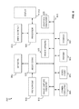
- FIG. 1 shows, in flowchart form, an image capture and fusion operation in accordance with one embodiment.
- FIGS. 2A-2C show illustrative intensity mapping functions.
- FIG. 3 shows, in flowchart form, an image evaluation and predicted image generation operation in accordance with one embodiment.
- FIG. 4 shows, in flowchart form, an image fusion weighting factor generation operation in accordance with one embodiment.
- FIG. 5 shows, in flowchart form, the generation of consistency-based weighting factors in accordance with one embodiment.
- FIG. 6 shows how a pixel neighborhood may be used in accordance with one embodiment.
- FIGS. 7A and 7B show, schematically, how intensity mapping functions may be adapted to account for inconsistent regions in accordance with one embodiment.
- FIG. 8 shows, in block diagram form, an electronic device in accordance with one embodiment.
- IMFs intensity mapping functions
- a reference image's pixel values when a reference image's pixel values are within the IMF's useful range, they may be used to generate predicted secondary image pixel values.
- actual values from a captured secondary image may be used to generate predicted secondary image pixel values.
- the predicted and actual pixel values may be used to construct a predicted secondary image.
- the resulting image When fused, the resulting image may be devoid of ghosting artifacts caused by relative motion between the reference and secondary images.
- IMFs may be used to determine weighting factors that can be used when fusing a reference and secondary images.
- Such factors may de-emphasize regions in the secondary images exhibiting relative motion with respect to the reference image.
- the resulting image may also be devoid of ghosting artifacts caused by relative motion between the images.
- AEB operations may be used during high dynamic range (HDR) imaging.
- HDR high dynamic range
- the full dynamic range of a scene needs to be captured (specifically, highlight and shadow information).
- the dynamic range of a scene often exceeds the dynamic range of an image capture device's sensor, which are typically limited to capturing 256 (for an 8-bit sensor) to 1024 (for a 10-bit sensor) levels of brightness or intensity.
- the most commonly employed brackets are: 2EV ⁇ , EV0, 2EV+ and 3EV ⁇ , EV0, 3EV+.
- EV stands for “exposure value” and refers to a combination of an image capture device's shutter speed and aperture setting.
- the EV0 image refers to the image captured using the exposure value determined by the device's auto-exposure (AE) mechanism.
- the EV+ image refers to the image captured at the AEB's higher stop (e.g., +2 or +3 relative to the EV0 image).
- the EV ⁇ image refers to the image captured at the AEB's lower stop (e.g., ⁇ 2 or ⁇ 3 relative to the EV0 image).
- operation 100 illustrates how multiple images may be captured and fused in accordance with one embodiment.
- AEB neutral image 105 (EV0) and bracket images 110 (EV+) and 115 (EV ⁇ ) may be captured (block 120 ).
- Forward (fIMF 125 ) and reverse rIMF 130 ) intensity mapping functions may then be obtained (block 135 ).
- Forward intensity mapping function fIMF 125 describes a mapping from EV0 image 105 pixel values to EV+ image 110 pixel values.
- reverse intensity mapping function rIMF 130 describes a mapping from EV0 image 105 pixel values to EV ⁇ image 115 pixel values.
- fIMF 125 and rIMF 130 functions may be linear functions (i.e., functions of constant slope). For example, if EV+ image 110 is captured with an EV that is 1 stop up from that used to capture EV0 image 105 , absent relative motion and noise, pixel values in EV+ image 110 should be twice that of the corresponding pixel value in EV0 image 105 . As such, reverse intensity mapping function rIMF 130 may be a value 0.5. In another embodiment, fIMF and rIMF functions 125 and 130 may be determined empirically.
- fIMF 125 may be based on the captured content of EV0 and EV+ images 105 , 110 while rIMF 130 may be based on the captured content of EV0 and EV ⁇ images 105 and 115 .
- empirically determined IMFs may be generated in a number of ways. For example, comparagrams and histogram approaches may be used. It will further be recognized that IMFs may exist between luminance (luma) pixel values for two luminance images in the YUV colorspace, as well as between pixel intensity values in the red (R) channels, the green (G) channels, and the blue (B) channels for images in the RGB colorspace.
- Bracket images 110 (EV+) and 115 (EV ⁇ ) may be evaluated based on their corresponding IMF, neutral image 105 (EV0) and knowledge about the image capture device's operational characteristics (block 140 ). Based on the evaluation's result, predicted bracket images 145 (pEV+) and 150 (pEV ⁇ ) may be generated (block 155 ) and fused with neutral EV0 image 105 (block 160 ) to generate output fused image 165 .
- ideal IMF 200 is shown as increasing monotonically as values along the abscissa or X-axis increase from 0 to some maximum value (MAX-X), so that at an X-axis value equal to MAX-X, the corresponding ordinate or Y-axis value equals its maximum value, MAX-Y.
- MAX-X some maximum value
- each pixel or pixel component, e.g., R, G or B
- MAX-X and MAX-Y may equal 255.
- actual forward IMF 205 uniquely maps EV0 pixel values between ‘A’ and ‘B’ to unique EV+ pixel values (i.e., every element in EV0 is paired with exactly one element of EV+).
- fIMF 205 is undefined; that is, the mapping between EV0 pixel values and EV+ pixel values is one to many and may leave a “guard band” to account for the following factors: sensor non-linearity, a pre-applied tone curve and noise.
- fIMF 205 can leave a similar “guard band” for the factors just cited.
- forward IMF 205 cannot be used to predict EV+ pixel values when EV0 values are less than A or greater than B. It will be recognized that during forward mapping operations, the image capture device's exposure values are being increased. As such, it is only the EV0 pixel values around the low-end cut-off value ‘A’ that are significant (i.e., pixels in EV0 that are already blown out high will continue to be blown out high in the EV+ image). Hence, the “guard band” for B may be ignored or set to MAX0, and forward IMF 205 may then be applied to EV0 pixel values greater than B. Referring next to FIG. 2C , reverse IMF 210 maps EV ⁇ pixel values to EV0 pixel values.
- EV0 pixel values greater than ‘C’ and less than ‘D’ correspond to unique EV ⁇ pixel values.
- fIMF 205 when EV0 pixel values are below C or greater than D, no unique EV ⁇ pixel value may be discerned and, as a consequence, rIMF 210 cannot be used to predict EV ⁇ values when EV0 values are less than C or greater than D.
- the image capture device's exposure values are being decreased. As such, it is only the EV0 pixel values around the high-end-cutoff value ‘D’ that are significant. (i.e., pixels in EV0 that are already blown-out low will continue to be blown-out low in the EV ⁇ image).
- values for A, B, C and D may vary from implementation to implementation—generally subject to the particular image capture system used. For example, in a very low noise device using an 8-bit sensor, A and C may be set to 2 or 3 while B and D may be set to 254 or 255 (for an 8-bit image sensor). In an image capture device exhibiting more noise, low cut-off values A and C may be set to 8-10 and high cut-off values B and D to 250. It should be recognized that cut-off values A, B, C and D may be set in accordance with design goals or empirically determined. Further, each of A, B, C and D may be different.
- image evaluation and predicted image generation function 300 begins by selecting a first pixel value from neutral or reference EV0 image 105 (block 305 ). A check may then be made to determine if the selected pixel's value is below that which the relevant IMF (i.e., fIMF 125 or rIMF 130 ) can provide a 1:1 mapping (block 310 ). Referring to FIGS. 2B and 2C , this could correspond to a value of A or C depending on whether fIMF 125 or rIMF 130 is being evaluated. As noted above, in practice it may only be necessary to check low-end pixel values when considering the forward mapping case: EV0 ⁇ EV+.
- a similar check may be made to determine if the selected EV0 pixel's value is greater than that which the relevant IMF can provide a 1:1 mapping (block 315 ). Again, in practice it may only be necessary to check high-end pixel values when considering the reverse mapping case: EV0 ⁇ EV ⁇ . Turning again to FIGS. 2B and 2C , this could correspond to a value of B or D depending on whether fIMF 125 or rIMF 130 is being evaluated.
- the EV0 pixel value may be applied to the relevant IMF to generate a predicted pixel value (block 320 ). This value may be retained as the value for the corresponding pixel in the relevant predicted bracket image (pEV+ 145 or pEV ⁇ 150 ).
- a further check may be made to determine if all pixels in reference EV0 image 105 have been processed (block 325 ). If there remain EV0 pixels to evaluate (the “YES” prong of block 325 ), the next EV0 pixel value may be obtained (block 330 ), where after operation 300 continues at block 310 .
- the selected EV0 pixel value is less than the relevant IMF low cut-off (the “YES” prong of block 310 ) or is greater that the relevant IMF high cut-off (the “YES” prong of block 315 )
- the corresponding pixel's value from the relevant bracket image (EV+ image 110 or EV ⁇ image 115 ) may be retained in the predicted bracket image (block 335 ).
- image completion or in-painting algorithms may be applied. (See discussion below.) Such approaches may reduce ghosting artifacts better than simply using the relevant bracket image's pixel value.
- Operations in accordance with FIGS. 1 and 3 permit multiple images to be fused while eliminating (or significantly mitigating) the effect of relative motion between the two. This can result in fused images that do not exhibit ghosting artifacts.
- operation 100 may be applied to only two images, or to 3 or more images.
- operations in accordance with FIGS. 1 and 3 evaluate a reference image relative to one or more secondary images.
- a reference image's pixel value When a reference image's pixel value is within a range of values that permit an intensity mapping function to provide a one-to-one mapping, the reference image's pixel value may be applied to the IMF to generate a predicted secondary image pixel value. Such a value represents the secondary image's content as it would appear without relative motion between itself and the reference image.
- predicted secondary image pixel values may be generated in part by the corresponding secondary image's pixel value and/or additional image processing techniques such as, for example, patch matching.
- the pixel value from the secondary image may be used. This may produce acceptable results if there is no (or very little) relative motion between the two images If there are, this approach may yield ghosting.
- the pixel value from the value predicted by the IMF may be checked for consistency with the existing secondary image pixel. If they are consistent, the secondary image pixel may be used. If they are not consistent, additional image processing techniques such as patch matching may be used.
- Consistent means that the secondary image's pixel's predicted value is approximately equal to the image's actual pixel value. This, in turn, may be determined in a number of ways.
- One way would be to take the absolute difference in the two pixels' values (or the square or their difference). If the resulting value is less than a specified threshold, the two pixels may be considered consistent.
- the precise threshold chosen may be a factor of the image capture device and/or other system constraints.
- IMFs may be used to determine weighting factors that can be used when fusing a reference and one or more secondary images. More particularly, IMFs may be used to determine how consistent pixels are between two images. The more consistent the two pixels, the larger the weighting factor used to combine or fuse the pixels during output image generation. The less consistent the two pixels, the smaller the weighting factor. Weighting factors determined in accordance with this approach tend to de-emphasize regions (pixels) in the two images exhibiting relative motion. As in the prior described approaches, images fused using weighting factors determined in accordance with this approach may also be devoid of ghosting artifacts.
- p out ⁇ ⁇ p ⁇ + ⁇ 0 p 0 + ⁇ + p +
- over all pixels EQ. 1
- p out represents the (fused) output pixel value
- p 0 represents a pixel value from the reference or EV0 image
- p ⁇ represents a pixel value from the EV ⁇ image corresponding to the p 0 pixel
- p + represents a pixel value from the EV+ image corresponding to the p 0 pixel
- ⁇ 0 , ⁇ ⁇ and ⁇ + represent prior art weighting factors.
- Weighting factors w 0 , ⁇ ⁇ and ⁇ + are generally a function of the pixels' value (e.g., luminosity or intensity). For example, if a pixel may take on the values 0 ⁇ 255, values in the middle of this range may be given a higher weight than values at either end.
- Prior art weighting factors ⁇ 0 , ⁇ ⁇ and ⁇ + may also incorporate image capture device noise characteristics.
- ⁇ c ⁇ (p 0 , p ⁇ ) represents a consistency-based weighting factor for combining pixels in the EV0 image with the EV ⁇ image
- ⁇ c + (p 0 , p + ) represents a consistency-based weighting factor for combining pixels in the EV0 image with the EV+ image
- p 0 , p ⁇ , p + , ⁇ 0 , ⁇ ⁇ and ⁇ + are as described above.
- consistency weighting factor determination operation 400 begins by obtaining images (block 405 ), e.g., EV0 105 , EV+ 110 and EV ⁇ 115 images.
- images e.g., EV0 105 , EV+ 110 and EV ⁇ 115 images.
- forward 125 and reverse 130 IMFs may be obtained (block 410 ), and a set of first pixels selected (block 415 ). For example, a first pixel value p 1 0 from the EV0 image and the corresponding pixel values from the EV+ and EV ⁇ images, p 1 + and p 1 ⁇ .
- the p 1 0 value may be applied to fIMF 125 to generate a predicted EV+ pixel value ⁇ circumflex over (p) ⁇ 1 +
- the p 1 ⁇ value may be applied to rIMF 130 to generate a predicted EV0 pixel value ⁇ circumflex over (p) ⁇ 1 0 (block 420 ).
- the consistency or similarity between the predicted and actual pixel values may be determined (block 425 ) and used to generate consistency weighting factors for each pixel (block 430 ).
- a check may then be performed to determine if all pixels in the EV0, EV+ and EV ⁇ images have been evaluated in accordance with blocks 420 - 430 (block 435 ).
- a next set of pixels may be selected (block 440 ), where after operation 400 continues at block 420 . If all pixels have been processed (the “YES” prong of block 435 ), the generated consistency weighting factors may be used to fuse the images (block 445 ). In another embodiment, the currently selected pixels may be fused immediately following the acts of block 430 . In this way a fused output image may be built up pixel-by-pixel as operation 400 progresses.
- routine 500 is directed toward generating consistency-based weighting factor ⁇ c + 505 (applied to pixels from EV+ image 110 during fusion in accordance with block 445 ).
- Routine 510 is directed toward generating consistency-based weighting factor ⁇ c ⁇ 515 (applied to pixels from EV ⁇ image 115 during fusion in accordance with block 445 ).
- p 0 and p ⁇ pixels may be obtained (blocks 520 and 525 ) and applied to the appropriate IMF (blocks 530 and 535 ) to generate predicted values ⁇ circumflex over (p) ⁇ + and ⁇ circumflex over (p) ⁇ 0 .
- compare actions 540 and 545 may be a simple absolute difference between the relevant pixel values:
- compare actions 540 and 545 may use a difference-squared operator: (p + ⁇ circumflex over (p) ⁇ + ) 2 and (p 0 ⁇ circumflex over (p) ⁇ 0 ) 2 .
- the ⁇ p + ( ⁇ p 0 ) value represents how similar or consistent the two pixel values are. For example, if the p + and ⁇ circumflex over (p) ⁇ + pixel values are precisely equal, this means that the EV0 and EV+ images are identical (after taking into account the difference in exposure values). If, on the other hand, the p + and ⁇ circumflex over (p) ⁇ + pixel values are very different, this means that there is very little consistency between the two (e.g., relative motion exists).
- ⁇ p + and ⁇ p 0 values may be used directly to determine consistency-based weighting factors 505 and 510 .
- ⁇ p + and ⁇ p 0 values may be applied to a Gaussian distribution such as:
- a, b, ⁇ 1 and ⁇ 2 are tuning parameters that may be adjusted by the developer to attain their desired goals.
- ⁇ p + and ⁇ p 0 values may be used as follow:
- c and d are tuning parameters.
- any monotonically decreasing function may be used. Whatever functional relationship is chosen, it should yield a smaller weighting factor the less consistent the two pixels are (e.g., the larger the value of ⁇ p + and ⁇ p 0 .
- neighborhood 600 may be used to “adjust” the value of pixel 605 —where pixel 605 represents the pixel selected in accordance with FIGS. 4 and 6 .
- the sum of each neighborhood pixel e.g., pixels A, B, C, D, E, F, G, H and 605
- the mean or median of pixel values in 605 's neighborhood 600 may be used.
- the maximum of the values in neighborhood 600 may be selected. In another embodiment, the minimum of the values in neighborhood 600 may be selected. In yet other embodiments, neighborhoods other than square neighborhoods may be selected. In addition, where neighborhood pixels do not exist because the selected pixel is along an image's border, contribution from such pixels may be ignored or, alternatively, values from those neighborhood pixels that do exist may be reflected across the image's border.
- fIMF 700 it may be determined that one or more regions in image pairs EV0/EV+ and EV ⁇ /EV0 are inconsistent.
- region 705 between EV0 image 710 and EV+ image 715 are inconsistent (i.e., their pixel values differ by more than a specified amount or threshold value). It has been found that when this is the case the empirically generated intensity mapping function may be “skewed.” Further, the more inconsistent pixels in region 705 are, the more skewed the IMF may become. It has also been found that when inconsistent pixels are ignored when determining an IMF, the quality of the resulting weighting factors (and therefore the fused output image) may be unexpectedly improved. This situation may be seen in FIG. 7B where fIMF 700 ′ was generated using EV0 image 710 ′ (image 710 with pixels from region 705 removed) and EV+ image 715 ′ (image 715 with pixels from region 705 removed).
- Electronic device 800 may include processor 805 , display 810 , user interface 815 , graphics hardware 820 , device sensors 825 (e.g., proximity sensor/ambient light sensor, accelerometer and/or gyroscope), microphone 830 , audio codec(s) 835 , speaker(s) 840 , communications circuitry 845 , digital image capture unit 850 , video codec(s) 855 , memory 860 , storage 865 , and communications bus 870 .
- device sensors 825 e.g., proximity sensor/ambient light sensor, accelerometer and/or gyroscope
- microphone 830 e.g., microphone 830 , audio codec(s) 835 , speaker(s) 840 , communications circuitry 845 , digital image capture unit 850 , video codec(s) 855 , memory 860 , storage 865 , and communications bus 870 .
- Electronic device 800 may be, for example, a personal digital assistant (PDA), personal music player, a mobile telephone, or a workstation, desktop, notebook, laptop or tablet computer system.
- PDA personal digital assistant
- An accurate IMF, robust to inconsistent pixels may be found in an iterative manner.
- a first estimate of the IMF may be found based on examining all corresponding image pixels in the two images. This IMF estimate, together with corresponding pixel values in the two images may be used to detect inconsistent pixels. These pixels can then excluded and a second estimate of the IMF using only consistent pixels obtained. This process can be repeated for a small number of fixed iterations, or until the estimated IMF converges to fixed value.
- Processor 805 may execute instructions necessary to carry out or control the operation of many functions performed by device 800 (e.g., such as the generation and/or processing of images in accordance with this disclosure). Processor 805 may, for instance, drive display 810 and receive user input from user interface 815 . User interface 815 can take a variety of forms, such as a button, keypad, dial, a click wheel, keyboard, display screen and/or a touch screen. Processor 805 may be a system-on-chip such as those found in mobile devices and include a dedicated graphics processing unit (GPU). Processor 805 may be based on reduced instruction-set computer (RISC) or complex instruction-set computer (CISC) architectures or any other suitable architecture and may include one or more processing cores. Graphics hardware 820 may be special purpose computational hardware for processing graphics and/or assisting processor 805 process graphics information. In one embodiment, graphics hardware 820 may include a programmable graphics processing unit (GPU).
- GPU programmable graphics processing unit
- Sensor and camera circuitry 850 may capture still and video images that may be processed to generate images in accordance with this disclosure. Output from camera circuitry 850 may be processed, at least in part, by video codec(s) 855 and/or processor 805 and/or graphics hardware 820 , and/or a dedicated image processing unit incorporated within circuitry 850 . Images so captured may be stored in memory 860 and/or storage 865 .
- Memory 860 may include one or more different types of media used by processor 805 , graphics hardware 820 , and image capture circuitry 850 to perform device functions. For example, memory 860 may include memory cache, read-only memory (ROM), and/or random access memory (RAM).
- Storage 865 may store media (e.g., audio, image and video files), computer program instructions or software, preference information, device profile information, and any other suitable data.
- Storage 865 may include one more non-transitory storage mediums including, for example, magnetic disks (fixed, floppy, and removable) and tape, optical media such as CD-ROMs and digital video disks (DVDs), and semiconductor memory devices such as Electrically Programmable Read-Only Memory (EPROM), and Electrically Erasable Programmable Read-Only Memory (EEPROM).
- Memory 860 and storage 865 may be used to retain computer program instructions or code organized into one or more modules and written in any desired computer programming language. When executed by, for example, processor 805 such computer program code may implement one or more of the methods described herein.
Abstract
Description
p out=ω− p −+ω0 p 0+ω+ p +|over all pixels, EQ. 1
where pout represents the (fused) output pixel value, p0 represents a pixel value from the reference or EV0 image, p− represents a pixel value from the EV− image corresponding to the p0 pixel, p+ represents a pixel value from the EV+ image corresponding to the p0 pixel, and ω0, ω− and ω+ represent prior art weighting factors. Weighting factors w0, ω− and ω+ are generally a function of the pixels' value (e.g., luminosity or intensity). For example, if a pixel may take on the
p out=ωc −(p 0 ,p −)ω− p −+ω0 p 0+ωc +(p 0 ,p +)ω+ p +|over all pixels, EQ. 2
where ωc −(p0, p−) represents a consistency-based weighting factor for combining pixels in the EV0 image with the EV− image, ωc +(p0, p+) represents a consistency-based weighting factor for combining pixels in the EV0 image with the EV+ image, and p0, p−, p+, ω0, ω− and ω+ are as described above.
where a, b, σ1 and σ2 are tuning parameters that may be adjusted by the developer to attain their desired goals. In another embodiment, Δp+ and Δp0 values may be used as follow:
where c and d are tuning parameters. In practice, any monotonically decreasing function may be used. Whatever functional relationship is chosen, it should yield a smaller weighting factor the less consistent the two pixels are (e.g., the larger the value of Δp+ and Δp0.
Claims (38)
Priority Applications (1)
| Application Number | Priority Date | Filing Date | Title |
|---|---|---|---|
| US13/490,259 US8675964B2 (en) | 2012-06-06 | 2012-06-06 | Image fusion using intensity mapping functions |
Applications Claiming Priority (1)
| Application Number | Priority Date | Filing Date | Title |
|---|---|---|---|
| US13/490,259 US8675964B2 (en) | 2012-06-06 | 2012-06-06 | Image fusion using intensity mapping functions |
Publications (2)
| Publication Number | Publication Date |
|---|---|
| US20130330001A1 US20130330001A1 (en) | 2013-12-12 |
| US8675964B2 true US8675964B2 (en) | 2014-03-18 |
Family
ID=49715369
Family Applications (1)
| Application Number | Title | Priority Date | Filing Date |
|---|---|---|---|
| US13/490,259 Active US8675964B2 (en) | 2012-06-06 | 2012-06-06 | Image fusion using intensity mapping functions |
Country Status (1)
| Country | Link |
|---|---|
| US (1) | US8675964B2 (en) |
Families Citing this family (4)
| Publication number | Priority date | Publication date | Assignee | Title |
|---|---|---|---|---|
| CN105631467A (en) * | 2015-12-18 | 2016-06-01 | 小米科技有限责任公司 | Method and device for displaying picture |
| CN109005366B (en) * | 2018-08-22 | 2020-04-28 | Oppo广东移动通信有限公司 | Night scene shooting processing method and device for camera module, electronic equipment and storage medium |
| CN110751639A (en) * | 2019-10-16 | 2020-02-04 | 黑龙江地理信息工程院 | Intelligent assessment and damage assessment system and method for rice lodging based on deep learning |
| CN112233079B (en) * | 2020-10-12 | 2022-02-11 | 东南大学 | Method and system for fusing images of multiple sensors |
Citations (6)
| Publication number | Priority date | Publication date | Assignee | Title |
|---|---|---|---|---|
| US6611615B1 (en) * | 1999-06-25 | 2003-08-26 | University Of Iowa Research Foundation | Method and apparatus for generating consistent image registration |
| US7349574B1 (en) * | 2002-10-11 | 2008-03-25 | Sensata Technologies, Inc. | System and method for processing non-linear image data from a digital imager |
| US7522781B2 (en) * | 2005-02-11 | 2009-04-21 | Samsung Electronics Co., Ltd. | Method and apparatus for image processing based on a mapping function |
| US7835594B2 (en) * | 2006-12-01 | 2010-11-16 | Harris Corporation | Structured smoothing for superresolution of multispectral imagery based on registered panchromatic image |
| US7936949B2 (en) * | 2006-12-01 | 2011-05-03 | Harris Corporation | Panchromatic modulation of multispectral imagery |
| US8131109B2 (en) * | 2006-06-09 | 2012-03-06 | Samsung Electronics Co., Ltd. | Image processing method and apparatus for contrast enhancement using intensity mapping |
-
2012
- 2012-06-06 US US13/490,259 patent/US8675964B2/en active Active
Patent Citations (6)
| Publication number | Priority date | Publication date | Assignee | Title |
|---|---|---|---|---|
| US6611615B1 (en) * | 1999-06-25 | 2003-08-26 | University Of Iowa Research Foundation | Method and apparatus for generating consistent image registration |
| US7349574B1 (en) * | 2002-10-11 | 2008-03-25 | Sensata Technologies, Inc. | System and method for processing non-linear image data from a digital imager |
| US7522781B2 (en) * | 2005-02-11 | 2009-04-21 | Samsung Electronics Co., Ltd. | Method and apparatus for image processing based on a mapping function |
| US8131109B2 (en) * | 2006-06-09 | 2012-03-06 | Samsung Electronics Co., Ltd. | Image processing method and apparatus for contrast enhancement using intensity mapping |
| US7835594B2 (en) * | 2006-12-01 | 2010-11-16 | Harris Corporation | Structured smoothing for superresolution of multispectral imagery based on registered panchromatic image |
| US7936949B2 (en) * | 2006-12-01 | 2011-05-03 | Harris Corporation | Panchromatic modulation of multispectral imagery |
Non-Patent Citations (9)
| Title |
|---|
| "Image Fusion using the Intensity Mapping Function," Apple Inc. Mar. 9-12, 2012. pp. 1-41. |
| Gallo, Orazio, Natasha Gelfand, Wei-Chao Chen, Marius Tico and Kari Pulli. "Artifact-free High Dynamic Range Imaging." Nokia Research Center. Palo Alto, CA. pp. 1-7. |
| Gossberg, Michael D. and Shree K. Nayar. "Deterrming the Camera Response from Images: What is Knowable?" IEEE Transactions on Pattern Analysis and Machine Intelligence, vol. 25, No. 11. Nov. 2003 pp. 1465-1467. |
| Hossain, Imtiaz and Bahadir K. Gunturk. "High Dynamic Range Imaging of Non-Static Scenes." Dept. of Electrical and Computer Engineering-Louisiana State University. Baton Rouge, LA. pp. 1-8. |
| Neemuchwala, Huzefa and Alfred Hero. "Entropic Graphs for Registration." Jun. 1, 2004. pp. 1-49. |
| Rao, Ch. Venkateswara, K.M.M. Rao, A.S. Manjunath and R.V.N. Srinivas. "Optimization of Automatic Image Registration Algorithms and Characterization." National Remote Sensing Agency: Hyderabad, India. pp. 1-6. |
| Saleem, Amina, Azeddine Beghdadi and Boualem Boashash. "Image Fusion-Based Contrast Enhancement." EURASIP Journal on Image and Video Processing 2012, 2012:10, http://www.springeropen.com pp. 1-55. |
| Wong, Alexander and William Bishop. "Efficient Least Squares Fusion of MRI and CT Images Using a Phase Congruency Model." www.sciencedirect.com Oct. 11, 2007. pp. 1-8. |
| Yao, W., Z. G. Li and S. Rahardja. "Intensity Mapping Function Based Weighted Frame Averaging for High Dynamic Range Imaging." Signal Processing Dept., Institute for Infocomm Research: Singapore. pp. 1-4, 2011. |
Also Published As
| Publication number | Publication date |
|---|---|
| US20130330001A1 (en) | 2013-12-12 |
Similar Documents
| Publication | Publication Date | Title |
|---|---|---|
| US9407831B2 (en) | Intelligent auto-exposure bracketing | |
| EP2987135B1 (en) | Reference image selection for motion ghost filtering | |
| US20210256669A1 (en) | Unified Bracketing Approach for Imaging | |
| EP3170304B1 (en) | Method and apparatus for detecting imaging conditions | |
| CN108668093B (en) | HDR image generation method and device | |
| US9380218B2 (en) | Highlight exposure metric and its applications | |
| US10861136B2 (en) | Image processing apparatus, image processing method, and storage medium | |
| US10097802B2 (en) | Image processing technique for reducing moire | |
| JP6720881B2 (en) | Image processing apparatus and image processing method | |
| US20150163391A1 (en) | Image capturing apparatus, control method of image capturing apparatus, and non-transitory computer readable storage medium | |
| US10091422B2 (en) | Image processing device and recording medium | |
| US8755600B2 (en) | Method and apparatus for determining the light direction | |
| WO2020034701A1 (en) | Imaging control method and apparatus, electronic device, and readable storage medium | |
| US20120127336A1 (en) | Imaging apparatus, imaging method and computer program | |
| JP2015156600A (en) | Image signal processor, image signal processing method, and imaging apparatus | |
| US9282235B2 (en) | Focus score improvement by noise correction | |
| US9654668B2 (en) | Image composition apparatus and image composition method | |
| US8675964B2 (en) | Image fusion using intensity mapping functions | |
| US20160196640A1 (en) | Image processing apparatus, imaging apparatus, and image processing method | |
| US10271029B2 (en) | Image pickup apparatus and method of controlling an image pickup apparatus | |
| US11887286B2 (en) | Image processing device and image processing method to generate image for object recognition | |
| US8390693B2 (en) | Image processing apparatus | |
| JP2008305122A (en) | Image-processing apparatus, image processing method and program | |
| US9288461B2 (en) | Apparatus and method for processing image, and computer-readable storage medium | |
| US8897589B2 (en) | Method of detecting subject of image and imaging device thereof |
Legal Events
| Date | Code | Title | Description |
|---|---|---|---|
| AS | Assignment |
Owner name: APPLE INC., CALIFORNIA Free format text: ASSIGNMENT OF ASSIGNORS INTEREST;ASSIGNORS:WONG, EARL Q.;HORDLEY, STEVEN D.;REEL/FRAME:028330/0954 Effective date: 20120605 |
|
| FEPP | Fee payment procedure |
Free format text: PAYOR NUMBER ASSIGNED (ORIGINAL EVENT CODE: ASPN); ENTITY STATUS OF PATENT OWNER: LARGE ENTITY |
|
| STCF | Information on status: patent grant |
Free format text: PATENTED CASE |
|
| CC | Certificate of correction | ||
| MAFP | Maintenance fee payment |
Free format text: PAYMENT OF MAINTENANCE FEE, 4TH YEAR, LARGE ENTITY (ORIGINAL EVENT CODE: M1551) Year of fee payment: 4 |
|
| MAFP | Maintenance fee payment |
Free format text: PAYMENT OF MAINTENANCE FEE, 8TH YEAR, LARGE ENTITY (ORIGINAL EVENT CODE: M1552); ENTITY STATUS OF PATENT OWNER: LARGE ENTITY Year of fee payment: 8 |