US8670972B1 - Method and apparatus for voice recognition unit simulation - Google Patents
Method and apparatus for voice recognition unit simulation Download PDFInfo
- Publication number
- US8670972B1 US8670972B1 US11/759,659 US75965907A US8670972B1 US 8670972 B1 US8670972 B1 US 8670972B1 US 75965907 A US75965907 A US 75965907A US 8670972 B1 US8670972 B1 US 8670972B1
- Authority
- US
- United States
- Prior art keywords
- call
- function
- simulated
- functional logic
- vru
- Prior art date
- Legal status (The legal status is an assumption and is not a legal conclusion. Google has not performed a legal analysis and makes no representation as to the accuracy of the status listed.)
- Active, expires
Links
Images


Classifications
-
- G—PHYSICS
- G10—MUSICAL INSTRUMENTS; ACOUSTICS
- G10L—SPEECH ANALYSIS OR SYNTHESIS; SPEECH RECOGNITION; SPEECH OR VOICE PROCESSING; SPEECH OR AUDIO CODING OR DECODING
- G10L15/00—Speech recognition
-
- G—PHYSICS
- G06—COMPUTING; CALCULATING OR COUNTING
- G06F—ELECTRIC DIGITAL DATA PROCESSING
- G06F11/00—Error detection; Error correction; Monitoring
- G06F11/36—Preventing errors by testing or debugging software
- G06F11/3664—Environments for testing or debugging software
-
- G—PHYSICS
- G06—COMPUTING; CALCULATING OR COUNTING
- G06F—ELECTRIC DIGITAL DATA PROCESSING
- G06F30/00—Computer-aided design [CAD]
- G06F30/20—Design optimisation, verification or simulation
-
- G—PHYSICS
- G10—MUSICAL INSTRUMENTS; ACOUSTICS
- G10L—SPEECH ANALYSIS OR SYNTHESIS; SPEECH RECOGNITION; SPEECH OR VOICE PROCESSING; SPEECH OR AUDIO CODING OR DECODING
- G10L15/00—Speech recognition
- G10L15/01—Assessment or evaluation of speech recognition systems
-
- H—ELECTRICITY
- H04—ELECTRIC COMMUNICATION TECHNIQUE
- H04L—TRANSMISSION OF DIGITAL INFORMATION, e.g. TELEGRAPHIC COMMUNICATION
- H04L43/00—Arrangements for monitoring or testing data switching networks
- H04L43/50—Testing arrangements
-
- H—ELECTRICITY
- H04—ELECTRIC COMMUNICATION TECHNIQUE
- H04M—TELEPHONIC COMMUNICATION
- H04M1/00—Substation equipment, e.g. for use by subscribers
- H04M1/24—Arrangements for testing
-
- H—ELECTRICITY
- H04—ELECTRIC COMMUNICATION TECHNIQUE
- H04M—TELEPHONIC COMMUNICATION
- H04M3/00—Automatic or semi-automatic exchanges
- H04M3/22—Arrangements for supervision, monitoring or testing
- H04M3/2227—Quality of service monitoring
-
- H—ELECTRICITY
- H04—ELECTRIC COMMUNICATION TECHNIQUE
- H04M—TELEPHONIC COMMUNICATION
- H04M3/00—Automatic or semi-automatic exchanges
- H04M3/42—Systems providing special services or facilities to subscribers
- H04M3/487—Arrangements for providing information services, e.g. recorded voice services or time announcements
- H04M3/493—Interactive information services, e.g. directory enquiries ; Arrangements therefor, e.g. interactive voice response [IVR] systems or voice portals
- H04M3/4936—Speech interaction details
-
- G—PHYSICS
- G06—COMPUTING; CALCULATING OR COUNTING
- G06F—ELECTRIC DIGITAL DATA PROCESSING
- G06F9/00—Arrangements for program control, e.g. control units
- G06F9/06—Arrangements for program control, e.g. control units using stored programs, i.e. using an internal store of processing equipment to receive or retain programs
- G06F9/44—Arrangements for executing specific programs
- G06F9/455—Emulation; Interpretation; Software simulation, e.g. virtualisation or emulation of application or operating system execution engines
-
- H—ELECTRICITY
- H04—ELECTRIC COMMUNICATION TECHNIQUE
- H04L—TRANSMISSION OF DIGITAL INFORMATION, e.g. TELEGRAPHIC COMMUNICATION
- H04L41/00—Arrangements for maintenance, administration or management of data switching networks, e.g. of packet switching networks
- H04L41/14—Network analysis or design
- H04L41/145—Network analysis or design involving simulating, designing, planning or modelling of a network
Definitions
- This invention relates generally to testing of telecommunication systems and, more particularly, to simulation testing relating to voice recognition systems.
- VRU Voice Recognition Unit
- IVR Interactive Voice Recognition
- EOS Electronic Voice Recognition
- the VRU consists of different components (software/daemons), which perform their respective tasks.
- the invention is an apparatus and/or computer software to automate testing of a voice self service platform.
- the present invention comprises software that is operable to run on a WINDOWS® platform to simulate all the components of an Interactive Voice Recognition Unit (VRU).
- VRU Interactive Voice Recognition Unit
- the present invention can be adapted to operate on other platforms without departing from the scope of the invention.
- this embodiment can also be used as a helper unit to test individual components of an interactive voice recognition system (IVR).
- IVR interactive voice recognition system
- the present invention comprises a full simulator and helper VRU.
- the components are tightly coupled and the interaction between them is seemingly adaptive. With the help of an in build ‘call calculator’ the unit is able to generate and maintain a required sustained load.
- the simulator is also built on “integration middleware”, whereby the simulator functionality is well isolated from the data integration and transport layer. Also the simulator draws a strong analogy to the existing telephony hardware grouping such as T-1s and trunk groups.
- the simulator is comprised of the following six components: Dialer and Manager, Call generator and VRU monitor, Telecom IN, VOX, ASR, Telecom OUT.
- Telecom switch which generates multiple simultaneous calls with intricate details such as pull back of timeout calls, ADR functionality
- Telecom bridge for the transfer functionality
- voice device interaction with the COM device, and the TTS engine
- caller interaction for the ASR functionality.
- these emulators can emulate various system level failures.
- the XML driven call engine can simulate calls with millisecond precision and hence able to replicate the call scenario to the closest approximation. Multiple components of the simulator is closely watched by a watcher application. Multiple simulators can be integrated together with the concept of ‘dialer’ acting as a management tool that will monitor the different units. This way it is possible to generate a large volume for the load test.
- the simulator design for the present invention is very cost effective (ie., does not require any special hardware) and millions of calls can be generated for ‘zero cost’ paring the usage of existing desktop and intranet hardware.
- FIG. 1 is a functional diagram of the VRU components
- FIG. 2 is an illustration of message transport layer
- FIG. 3 is an illustration of a message transport layer
- FIG. 4 is an illustration of a simulation system
- FIG. 5 is an illustration of a main console user interface
- FIGS. 6 through 14 are an illustration of various user interfaces for control and monitoring
- FIG. 15 is a flow diagram for running a simulation test
- FIG. 16 is an illustration of the relational database tables
- FIG. 17 is an illustration of typical Cgvm Calls DB Fields
- FIG. 18 is an illustration of typical Browser Call fields
- FIG. 19 is an illustration of typical EOS Event DB Fields
- FIG. 20 is an illustration of Call Statistics DB Fields
- FIG. 20A is an illustration of Incidents DB Fields
- FIGS. 21-24 is an illustration of the simulated and Help View.
- FIG. 25 lists the messages that can be handled specific to its functionality
- FIG. 26 is a snap shot of the ASR dashboard with its controls.
- FIG. 27 the controls specific to the ASR are numbered.
- FIG. 28 lists the messages that need to be handled specific to its functionality.
- FIG. 29 is a snap shot of the TelecomOUT dashboard with its controls.
- FIG. 30 the controls specific to the TelecomOUT are numbered.
- FIG. 31 the controls specific to the hardware configuration are numbered.
- FIG. 32 is an overview of TelecomIN hardware emulation which is one of the main components of the CVSS.
- FIG. 33 shows the data flow of how the ring event is been handled.
- FIG. 34 shows the data flow of how the answer event is been handled.
- FIG. 35 shows the data flow of how the hangup event is been handled.
- FIG. 36 illustrates different scenarios under which the telecom network will null back the call.
- FIG. 37 The logic and decision tree behind the voice device emulation is shown.
- FIG. 38 the inside architecture of the DTMF generator is detailed.
- FIG. 39 shows the data flow of how the play event is been handled.
- FIG. 40 the decision make logic of how and what binaries get queued for playing is illustrated.
- FIG. 41 event synchronization is illustrated.
- FIG. 42 utterance play is illustrated.
- FIG. 43 explains the timing diagram involved in setting up the MRCP recognition session in a VRU.
- FIG. 44 complete simulated VRU is illustrated.
- FIG. 45-50 the timing diagram for the barginable and non-barginable recognition prompts where the caller barges in or not, under single or multiple users mode is explained.
- FIG. 51 illustrates how a real VOX daemon is used in conjunction with the simulator.
- FIG. 52 illustrates how a real mrcp-ASR daemon is used in conjunction with the simulator.
- FIG. 52-58 the timing diagram for the barginable and non-barginable recognition prompts where the caller barges in or not, under single or multiple users mode is explained.
- FIG. 59 the redirector in a complete simulator is illustrated.
- FIG. 60 the collision of the dialogic device utilization is illustrated.
- FIG. 61 illustrates the out-dial's design of generating inputs in a pre defined intervals.
- FIG. 62 illustrates the way the hammer functions. It relies on the detection or absence of the voice energy.
- FIG. 63 the application input sets conformance to the WicSimulatorApp.dtd and WicSimInputSet.dtd and the layout is detailed.
- FIG. 64 shows different ways to create the input set.
- FIG. 65 is a snap shot of the editor to generate call flow input set.
- FIG. 66 is an example of an utterance data and its type.
- FIG. 67 is a single application set flow chart.
- FIG. 68 is a hammer subset flow chart.
- FIG. 68A CgvmCalls DB Fields are illustrated.
- FIG. 68B BrowserCalls DR Fields are illustrated.
- FIG. 68C EosEvent is illustrated.
- FIG. 68D CallStatistics DB Fields are illustrated.
- FIG. 68E typical incidents DB Fields are illustrated.
- FIG. 69 the controls specific to the test set report are numbered.
- FIG. 70 the controls specific to the call trace file explorer are numbered.
- FIG. 71 the controls specific to the username and password validation are numbered.
- FIG. 72 the controls specific to the remote software upgrade are numbered.
- FIG. 73 the controls specific to the call calculation are numbered.
- FIG. 74 other loads type are illustrated.
- FIG. 75 cyclic load pattern is illustrated.
- FIG. 76 peak call pattern is illustrated.
- FIG. 77 shows the burst call pattern.
- FIG. 78 choppy call pattern is illustrated.
- FIG. 79 sustained call pattern is illustrated.
- FIG. 80 is a flow chart that depicts an outcome if a sustained minimum percentage is equivalent to a requested sustained minimum percentage.
- FIG. 81 is a flow chart that depicts an outcome of a register channel live state event.
- FIG. 82 is a flow chart that depicts an outcome of an active or an inactive call.
- FIG. 83 is a flow chart that depicts an evaluate call distribution event.
- FIG. 84 is a flow chart that depicts calls a per hour event.
- FIG. 85 is a diagram that depicts various client specific applications.
- FIG. 86 D-Channel polling is illustrated.
- FIG. 87 CSA-Hammer platform monitoring is illustrated.
- FIG. 88 client application call flow variation testing is illustrated.
- FIG. 89 depicts a system diagram according to one embodiment.
- FIG. 90 explains the synchronization process required for the CSA-Hammer business logic templates.
- FIG. 1-24 various views are illustrated in FIG. 1-24 and like reference numerals are being used consistently throughout to refer to like and corresponding parts of the invention for all of the various views and figures of the drawing.
- first digit(s) of the reference number for a given item or part of the invention should correspond to the Fig. number in which the item or part is first identified.
- VRU simulation components for a dialer, call generator, TelecomIN, Vox, ASR, and TelecommOut teaches a novel apparatus and method for simulating a VRU in a development and testing environment.
- the VXML browser and the application server can be the actual units. There can be the ability to use the real VOX aid or ASR daemon from the VRU which will be used in the development.
- Hardware functionality components are mainly the emulated components that are intrinsically needed for the simulator functionality.
- the application engine has whole processing and interpretive software along with its XML based application specific drivers. The whole system is configured and tuned with external settings. This design makes the installation dynamic and increases its versatility for future expansion.
- Microsoft Access based database interface can be included to capture the run time events and statistics. Later in this document, each one of these modules will be explained in detail in their respective sections.
- GUI graphic user interface
- MFC Microsoft Foundation Component
- GUI is used mainly to change any settings and to watch or monitor the operation. Since the process controller engine has all the required input it allows certain module to run in the invisible mode.
- VRU simulation invention The details of the present VRU simulation invention and various embodiments can be better understood by referring to the figures of the drawing. It should be noted that a VRU can sometimes be referred to as an Interactive Voice Recognition (IVR) system by those skilled in the art area and this terminology may be used herein.
- IVR Interactive Voice Recognition
- a typical VRU comprises different components (software/daemons), which perform their respective tasks.
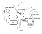
- FIG. 1 shows the typical components of a VRU, which is useful in understanding what functions of the VRU are simulated in the present invention.
- the broken lines illustrating an application server indicates the possibility of running that respective application server either within the VRU itself or run as a separate server.
- a typical VRU/IVR 100 comprising a Telephony Interface board 102 .
- the ISDN is a typical telecommunication line that can transmit both voice and digital network services at a high speed.
- ISDN is a set of standard protocols for establishing and breaking circuit switched connections and advance call features useful for VRU systems.
- VXML Voice Extensible Markup Language
- Exp CLASS interpreter—Telephony language developed and maintained
- VXML-Browser VXML interpreter
- VXML Voice Extensible Markup Language
- Exp CLASS interpreter—Telephony language developed and maintained
- VXML-Browser VXML interpreter
- VXML Voice Extensible Markup Language
- VXML or VoiceXML
- technology allows a user to interact with a network through voice recognition technology. Instead of a traditional browser that relies on a combination of HTML (Hypertext Markup Language) and keyboard and mouse inputs, VXML relies on a voice browser and/or the telephone.
- VXML uses VXML, the user interacts with voice browser by listening to audio output that is either pre-recorded or computer-synthesized and submitting audio input through the user's natural speaking voice or through an input device, such as a telephone.
- the interpreter 118 can start the appropriate program based on the Dialed Number Identification Service (DNIS) in the ring message, which identifies what telephone number was dialed by the caller.
- DNIS is an abbreviation for dialed number identification service, a telephone service that identifies for the receiver what telephone number was dialed by the caller.
- PBX private branch exchange system
- a common use for this type of system phone numbers that channel multiple phone numbers into the same private branch exchange system (PBX) or private telephone network used within an enterprise. Once the call enters the PBX system, the DNIS will identify which number was dialed and record that information. This allows the VRU to categorize the type of incoming call.
- PBX private branch exchange system
- an application server 106 can be used, which generates dynamic VXML pages based on the program or business logic.
- the Voice Handling Software (VOX) daemon 112 can perform the task of playing the prompt, recording the utterance, DTMF playback for the A-side courtesy transfer, voice routing during bridge transfer and DTMF digit collection.
- Dual-tone multi-frequency (DTMF) signaling can be used for telephone signaling over the line in the voice-frequency band to the call switching center.
- DTMF Dual-tone multi-frequency
- the typical version of DTMF used for telephone tone dialing is known by the term Touch-Tone.
- a different version is used for signaling internal to the telephone network.
- DTMF is an example of a multifrequency shift keying (MFSK) system.
- Voice hardware devices for A-side and B-side channels can be on the dialogic board.
- the Automatic Speech Recognition (ASR) daemon 114 can perform the task of voice and DTMF recognition. This daemon can act as a liaison between ASR server 114 and the interpreter 118 . To perform the recognition task, this daemon can manage loading, activating, deactivating, unloading and freeing of the grammar. Once the ASR has performed the recognition task, it can provide the appropriate input representative of the recognized voice and DTMF to the Interpreter for processing.
- the Browser/Interpreter uses its voice browser functionality to start the appropriate program based on the DNIS and the input representative of the recognized voice and DTMF.
- the TelecomOUT 116 daemon can perform the task of call transfer. In this bridge transfer 108 , the VRU can hold on to the call till either A or B-side hangs up.
- the telephony applications for the browser/interpreter can be written in the following two interpretive languages—1. CLASS; 2. VXML (Industry standard).
- EXP is a typical CLASS language Interpreter. Normally EXP(s) can be run in each VRU, with 110% of the full capacity of the channels available in the VRU.
- the VXML Browser (interpreter) can interpret the VXML pages.
- VXML Browser is a server unit, which runs approximately 500 ( ⁇ 20 T1s capacity) instances of the browser.
- SALT Speech Application Language Tag
- SALT is a speech interface markup language. It consists of a small set of XML elements, with associated attributes and DOM object properties, events and methods, which apply a speech interface to web pages.
- DOM Document Object Module
- SALT can be used with HTML, XHTML and other standards to write speech interfaces for both voice-only (e.g. telephony) and multimodal applications.
- VXML coding For the Application Server in the VXML side of the telephony applications, normally writing directly VXML coding (which is also referred to as static VXML pages), can be avoided. The following are the main reasons behind this:
- VXML is a standard, which is a moving target. Any new specification changes means directly changing the software.
- VXML is an interpretive language and hence dynamic generation of these pages on the fly during the run time will not affect the performance.
- the application Server 202 closely works with the Interpreter. Refer to FIG. 2 .
- Interpreter sends an URL (servelet, cgi-script, EJB, JSP, ASP, etc.), request 204 to the app-server.
- the app-server sends back a snippet 206 of the VXML code, which contains the next program/business logic.
- the program/business logic necessary to be responsive to the caller input is executed.
- the VXML 208 interprets the current code and based on the result, makes the next URL request. The process goes on like this till any one of the following scenarios occurs:
- the call When the call lands on the VRU 210 , depending on where the interpreter software is running, the call might land on the browser server. If the application is generated dynamically, then the call chain might include an application server. At the maximum of three units might be involved in processing the call. So, any logging or tracing on a call could potentially be scattered on more than one unit.
- a Message Transport Layers (MTL) 202 and 204 or messaging layer can be developed for inter process communication (IPC).
- IPC inter process communication
- Each one of the services 306 and 308 involved in the call processing communicates with each other through the MTL 302 .
- the message sending service delivers the message to the manager function 310 .
- the manager function takes care of routing the message to the appropriate unit and the final manager function delivers the message to the appropriate destination service 212 .
- Both the source 306 and destination 308 services are on the same unit.
- the source service delivers the message to the manager, which in turn delivers the message the appropriate destination service.
- Source service 402 is one unit and destination service 404 is on another unit.
- Source service delivers the message to its manager 406 , which in turn delivers it to the destination unit's manager 408 .
- the final manager 410 delivers the message to the appropriate destination service 404 .
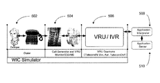
- FIG. 5 A typical telephony application development setup for a typical VRU as described above and its corresponding simulation approach taken, is shown in the FIG. 5 .
- the simulator program can be a WINDOWS® based program.
- the present invention can simulate the above described VRU Functions with the necessary monitors and controls to greatly enhance future VRU system developments for VRU systems designed to capture and respond to caller inquiries.
- the components that can be simulated by the present invention are:
- Dialer 502 Telephone equipment that the programmer/developer uses to place the call
- VRU 506 Components are:
- VXML browser 508 and the application server 510 can be the actual units. Note, that there is the ability to use the real VOX daemon from the VRU which can be used in the (VRU) development.
- the dialer function of the simulator requires the following four parameters to generate the load:
- the load can be categorized to the following types:
- Burst dump the calls in a burst (wait long enough to complete as much calls as possible
- the user of the simulator system can select from among the above parameters to simulate various call generation scenarios.
- the call calculator function of the simulator can estimate the load and stress level of during load simulation testing.
- CGVM Call Generator and VRU Monitor
- the Call Generator portion of this simulation function actually generates the ring message containing a computer generated DNIS.
- the VRU Monitor portion of this simulation functional portion can monitor operation parameters of the other simulated functions.
- the simulated ring message containing a DNIS can be transmitted to the VRU Daemons or functional simulation modules for further processing.
- one embodiment of the present simulation invention can utilize and interface with an actual Application Interpreter/VXML Browser and an actual Application Server rather than simulating these functions.
- the TelecomIN, VOX, ASR and TelecomOUT function can be simulated.
- the simulated TelecomIN daemon function can forward the simulated call to an actual Exp (CLASS interpreter—Telephony language developed and maintained or VXML-Browser (VXML interpreter) that is being utilized in conjunction with the simulation functions.
- VXML VXML-Browser
- the simulated call interacts with voice browser by listening to audio output.
- the interpreter can start the appropriate program based on the simulated DNIS in the ring message.
- the DNIS will identify which number was dialed and record that information.
- an application server can be used, which generates dynamic VXML pages based on the program or business logic.
- the simulated Voice Handling Software (VOX) daemon function can perform the task of playing a prompt function under test, recording a simulated utterance from the Dialer simulated function, DTMF playback for the A-side courtesy transfer, voice routing during bridge transfer and DTMF digit collection.
- Dual-tone multi-frequency (DTMF) signaling can be used for telephone signaling over the line in the voice-frequency band to the call switching center.
- DTMF Dual-tone multi-frequency
- the simulated Automatic Speech Recognition (ASR) daemon function can perform the task of voice and DTMF recognition. This simulated function can act as a liaison between the simulated ASR server and the actual interpreter. To perform the recognition task, this daemon can manage loading, activating, deactivating, unloading and freeing of the grammar.
- the simulated TelecomOUT daemon function can perform the task of call transfer. In this bridge transfer, the VRU can hold on to the call till either A or B-side hangs up.
- VXP is a typical CLASS language Interpreter.
- EXP(s) can be run in each VRU, with 110% of the full capacity of the channels available in the VRU.
- the VXML Browser can interpret the VXML pages.
- VXML Browser is a server unit, which runs approximately 500 ( ⁇ 20 T1s capacity) instances of the browser.
- SALT Speech Application Language Tag
- SALT is a speech interface markup language. It consists of a small set of XML elements, with associated attributes and DOM object properties, events and methods, which apply a speech interface to web pages.
- DOM is a platform- and language-neutral interface that will allow programs and scripts to dynamically access and update the content, structure and style of documents. The document can be further processed and the results of that processing can be incorporated back into the presented page.
- SALT can be used with HTML, XHTML and other standards to write speech interfaces for both voice-only (e.g. telephony) and multimodal applications.
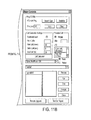
- FIG. 5 is a snap shot of the main console, which are common to all daemons.
- the controls and monitors are numbered in the figure and the explanation for each one of the items is as follows:
- the statistic refresh rate can be set to a high value so that the program concentrates on the other important work rather than refreshing the screen too often.
- the user could first select the appropriate application test set and subset by selecting a unique test set identification (UTSID). Then notify all the other daemons including the CGVM via the simulatorApp message to get prepared to initiate the test run. Later the user can select the appropriate call generation settings and select ‘run’ to start the test. The flow of this is shown in FIGS. 67 and 68 .
- the main purpose of the call calculator is to estimate the load and stress level during a load test.
- the dialer function of the simulator requires the following four parameters to generate the load:
- the load can be categorized to the following types:
- Burst dump the calls in a burst (wait long enough to complete as much calls as possible
- the general main console has the required controls for setting up the configuration for the messaging manager. Through these settings, each component can be connected to a local or a remote manager. But normally, since all the components are grouped together to form the whole CVSS unit, these settings do not change from the default settings. If needed the connection to the manager can be severed manually. Also, if the manager's configuration changes, the manager will be recycled to pick up the change and the activity log will report those occurrences.
- Each channel's emulated component runs on its own thread. This way of multithreaded architecture allows us to work on multiple channel requests simultaneously. Depending on how the application set is coded, appropriate response will be sent to the caller. After completing all these tasks, the inherited class will be released and the thread gets ready to process the next message to that channel.
- the multithreaded channels not only enhance working with multiple channel messages simultaneously, but also the extra time and processing performed closely approximates the real system. Further any timing related tasks for a particular channel can be performed without interfering with other channels. After elapse of certain time into the load test, because of natural lag and drag in the system, different channels will be at various stages of the call flow, which is how the real world calls progress.
- the parent-child-sibling relationship between the daemons is illustrated in the FIG. 9 .
- Each daemon queries the health status and statistics of daemon(s) one level down in its family tree structure. If needed the siblings interacts with each other only to fulfill the required functionality.
- the parent pings each one of its children for their statistics and is responsible for reporting own statistics to it's parent through ‘pong’ message. Every pong message is one stage lagging in informing its statistics. That is, when a daemon receives a ping message from its parent, it passes on the ping message to its children, but immediately responds with a ‘pong’ message to its parent with the last known statistics collected from the previous pong message from its children.
- FIG. 10 lists the messages that need to be handled specific to its functionality. The rest of the messages however are handled with generic message handling mechanism as explained above.
- the dialer can invoke one of many simultaneous calls.
- the single call scenario is unique in nature that the dialer can be notified of the call control (telecom processing) state which can be used either as a notification or to drive the next test set.
- the TelecomIN daemon will notify the dialer when it submits a ring message to the browser. In addition it will notify when an answer is received from the browser and when the call hangup is initiated. An answer message will be used to identify the browser and its virtual channel where the call is processed which out switching to the TelecomIN daemon. Hangup message is critical for the developer so that he could invoke the next call manually, or it will be used to proceed to the next auto dial test case automatically. This feature enables the CVSS to run the entire test suite back to back automatically.
- Dialer is the main dashboard used to control the entire simulator components. It has the ability to monitor multiple CGVMs.
- FIG. 11 is a snap shot of the dialer with its controls. The main functionalities of the dialer are:
- FIG. 12 Ref. Parameter Default Details version 1.1 Current version of the dialer configuration myDialer 900 Dialer group number. The selection of which CGVMs that this dialer can see is based on this value 2 autoPing 0 turn 5 pingInterval 60 statRefreshInterval 10 9 noOfCalls 1 10 interCallPeriod 50 11 batchCallPeriod 0 12 totalCallPeriod 24 8 sustainedLoad false 13 hungCallHangup true 14 hungCallSkipCount 1 18 simApp WIC_SysDev 19 simInputSet Load Test: Play- None. Asr-noinput
- FIG. 13 explains the relationship between these parameters.
- a batch of ‘N’ # of calls is generated 1302 at an interval of ‘inter-call-period’ 1304 . This process is repeated after the defined batch period 1308 . But, when the repetition batch follows, the # of calls generated 1306 will be subjective based on whether the previous call in the channel is completed or not.
- Parameters 13 and 14 in FIG. 12 determines this behavior. These parameters are inter-related with each other except for the total duration 1310 . Because of this, the total calls originated and call completion rate could vary based on the setting. A poor selection of value to these parameters could end of generating a large volume of calls because early termination of the calls before it could complete the entire business logic.
- FIG. 14 lists the messages that need to be handled specific to its functionality. The rest of the messages however are handled with generic message handling mechanism as explained above.
- FIG. 15 is a snap shot of the CGVM dashboard with its controls. In the real VRU, the following are the three locations where the different k-v pairs in the ring message are set.
- FIG. 16 Ref. Parameter Default Details version 1.2 Current version of the CGVM configuration statRefreshInterval 10 7 ani 4027160527 12 site 98 Please refer the list of site numbers assigned by the corporate 4 trunkGroup 900
- FIG. 17 illustrates the detailed flow chart in generating new call.
- Delivering the ring message to the browser marks the actual start of the call.
- the complexity of the ring generation comes due to the fact whether the load is sustained or driven by the CGVM.
- the call generation parameters such as number of available channels, call duration, calls per batch, inter call period, and batch repetition period are critical in generating the call volume.
- the pseudo ring request is generated from the CGVM and delivered to the appropriate channel in the TelecomIN.
- the channels in the TelecomIN are the once which has the current call status. For example, if the previous call has ended on the channel of current interest, then the send ring flag can be set which uses the telecom emulated hardware to generate the actual ring message to the browser. Subsequently when the dialer notifies the CGVM to stop the test, it can cease to send anymore ring request to TelecomIN thereby terminating the current test run.
- FIG. 18 lists the messages that need to be handled specific to its functionality. The rest of the messages however are handled with generic message handling mechanism as explained above.
- FIG. 19 is a snap shot of the TelecomIN dashboard with its controls.
- TelecomIN is mainly responsible for call generation and processing. In case of sustained load, this can play the role of auto ring generator too. This does not alter the ring message's k-v pairs set by the CGVM, and instead acts as a middle agent to pass it to the browser. All the call control functionalities are implemented including the appropriate timing for the state machine.
- FIG. 20 Ref. Parameter Default Details version 1.2 Current version of the TelecomIN configuration statRefreshInterval 10 clockOffsetRegion 0 clockOffsetEST 0 autoProceeding true proceedingTimer 10 autoAlerting false alertingTimer 120 hangupPrevious 1 callTime ⁇ 1
- FIG. 21 lists the messages that need to be handled specific to its functionality. The rest of the messages however are handled with generic message handling mechanism as explained above.
- FIG. 22 is a snap shot of the VOX dashboard with its controls. There is no parameter that needs to be controlled in the prompt play within the call flow. All the variations in the value can be programmed in the app input set which drives this daemon.
- this VOX daemon is mainly for a single call scenario to listen to the call flow.
- the load is identified as a multiple call scenario from the UTSID, then immediately the voice/speech features are turned off and the appropriate emulation for the prompt play can be executed instead, resulting in silence and the call will proceed.
- FIG. 23 Ref. Parameter Default Details version 1.1 Current version of the VOX configuration statRefreshInterval 10 2 speakAudio true 3 forceAudio false 4 storeAudio false
- FIG. 25 lists the messages that can be handled specific to its functionality. The rest of the messages, however, can be handled with generic message handling mechanism as explained above.
- FIG. 26 is a snap shot of the ASR dashboard with its controls.
- ASR Controls The controls specific to the ASR are numbered in FIG. 27 , and the explanation for each of the items is as follows:
- the browser waits on a timer which will be started after the end of the promptdone
- ASR Configuration Parameters The following are the list of parameters that can be configured externally.
- Fig. 27 De- Ref. Parameter fault Details version 1.2 Current version of the VOX configuration statRefreshInterval 10 timeslotReroute 500 2 autoNlSend true By setting this, the user dialog wait will not be invoked. Instead these default values will be automatically sent back 4 startRec 2000 Time before start speaking the utterance 3 bargedIn true The utterance was barged in during the prompt play 5 timeSpoke 1000 Utterance length in time 7 utterance grape Utterance string 7 textMode voice Utterance input mode text/DTMF asrNlsmlResult 1 Single/multiple NBest with/without slot 8 bestResult grape Interpretation 10 recConfidence 95.5 Confidence score on the interpreted string 11 grammarName ilg Matched grammar 12 grammarConfidence 97.5 Confidence score for the matched grammar 9 slotValueConf Additional slot, value, confidence k-v pairs
- FIG. 28 lists the messages that need to be handled specific to its functionality. The rest of the messages however are handled with generic message handling mechanism as explained above.
- FIG. 29 is a snap shot of the TelecomOUT dashboard with its controls.
- TelecomOUT Controls The controls specific to the TelecomOUT are numbered in the FIG. 30 , and the explanation for each of the items is as follows:
- TelecomOUT Configuration Parameters The following are the list of parameters that can be configured externally.
- the Manager function is an important part of the whole system. Hence, it can be started before starting the simulator(s). All the components of the VRU can be started to have a complete system.
- the order in which each daemon is started does not matter. However, one order is as follows:
- Each daemon can be a separate instance of the simulator program.
- To start the simulator from the ‘daemon list’ drop down menu, choose the daemon to be initiated and press the ‘MTL-Connect’ button.
- the activity log can display the entries for connecting the manager function. In case of failure, a repeated retry message can be displayed every I-second. If everything goes ok, you would see the “MTL progress indicator” pulsate, connect message on the activity window, and the appropriate socket name displayed.
- the same procedure as above can be followed.
- the Dialer can be selected by the operator ‘settings’ such that the operator would notice the presence of your CVGM.
- the following hardware units are the ones that can be either simulated or the actual operation performed.
- Telecom Ring Simulation basically by building appropriate “11 Ring” MTL Message in CGVM and sending to TelecomIN, the simulator can effectively have simulated a telecom ring event.
- an actual prompt can actually be generated and played or simply provide a simulation signal to prompt the simulated voice response.
- the ASR server is a key part of the recognition. Instead of sending the request to the ASR server, the present invention can simulate its functionalities in the ASR daemon itself.
- the actual operation can be performed in the case of a simulated voice response.
- Recognition Simulation the actual operation can also be performed.
- the system can essentially simulate the bridge transfer.
- the operator can throw a A-side hangup from the dialer or B-side hangup from the popup (raised after receiving the ‘29 dial’ MTL message) in the TelecomOUT daemon.
- the actual application server can be utilized as an interface to the simulator.
- the features of the application server can vary as also indicated above.
- the simulator can be used in at least the following four different areas:
- VRU's VOX and ASR daemon 3.
- the simulator can be utilized as a front end call load generator, which provides various voice inputs to test the various capabilities of the Interpreter.
- the same can apply with regard to Application Server Custom Objects Development.
- the Interpreter and Application development can be performed simultaneously utilizing the simulator.
- VRU, VOX and ASR development each of these module functions can be tested together or separately in a simulated environment.
- Fig. 31 Ref. Parameter Default Details Version 1.1 Current version of the hardware configuration 2 myUnit 9002 4 noOfT1 2 dChannel 1 5 channelSelection roundrobin 6 channelShare D 7 systemCheck false 8 realVoxVRU 9 realAsrVRU e1996 10 realMuxVRU 11 voxSpoofExp false 12 muteSpeech false 13 ttsProvider 2 14 ttsServerHostname linux730 15 ttsPortDefault 5555 16 ttsPortUtterance 5556
- FIG. 32 is an overview of TelecomIN hardware emulation which is one of the main components of the CVSS.
- FIG. 33 shows the data flow of how the ring event is been handled
- FIG. 34 shows the data flow of how the answer event is been handled
- FIG. 35 shows the data flow of how the hangup event is been handled
- FIG. 36 illustrates different scenarios under which the telecom network will pull back the call.
- the telecom network offers the ring message, it has to get response within a predefined amount of time. At various stages the actual time it waits differs.
- the network gives 4-seconds before the platform notifies proceeding (acknowledge the ring message and working on it). Normally, the platform is set to send auto proceeding at the time of ring arrival. This proceeding notification lets the network to provided additional 6-seconds grace period to answer or reject the call. If the platform does not respond within these timers, the network will pull back the call.
- the platform also can reject the call with user busy, there by invoking ADR functionality, such that if the number is provisioned with this feature, the call gets routed to another alternate site. But, if the platform decides that, it requires additional time to decide whether to accept the call or not, then it can send an alert notification, to the network. Upon receiving the alert notification, the network gives another grace period of about 2-minutes. At this point the platform looses the ability to do ADR. Also, during these grace periods, only one way audio (half-duplex) is set from the platform to the caller. Again, at this point if the call does not get answered in the next 2 minutes, the call will be pulled back by the network.
- Caller Hangup The following are the list of different circumstances under which an equivalence of caller hangup scenario will be raised:
- Prompt Engine Emulation The logic and decision tree behind the voice device emulation is shown in FIG. 37 .
- DTMF signal Generator Each digit in the given string is parsed and for each digit, the respective audio binary is concatenated to generate DTMF play back of sequence of digits.
- the DTMF digits consist of digits 0-9, pound (#), and start (*).
- the inside architecture of the DTMF generator is detailed in FIG. 38 .
- FIG. 39 shows the data flow of how the play event is been handled
- the speech glue layer is a middleware which provides the APIs to handle the speech functionality. Based on the environment (hardware & operating system), the Application Program Interface (API) could be inherited and expanded. Currently, since the CVSS runs only on the windows system, COM device interface is used. The prompt could be either from the recorded audio, or text data. In case of recorded audio, the file need to be fetched from an external server and converted to the way file format to play on the COM device. For the text data, it needs to be passed to an external TTS server to generate the audio binary and will be played on the COM device. Interface to the external TTS server could be standards based (MRCP) or native API.
- MCP standards based
- ASR server is a key part of the recognition. Instead of sending the request to the ASR server we have simulated its functionalities in the ASR daemon itself.
- Grammar Manipulation The grammar manipulation features such as load, activate, deactivate, and free and handled in this level. This is simple and straight forward implementation. Basically when a load request is made, a new entry is updated to keep track of all the loaded grammars. Current activate and deactivate statuses are updated to the loaded list of grammars. When requested or on the call hangup the loaded grammars are freed. Currently for the simplification, the grammars are not validated. When the recognizer need to compute the result, and if the grammar is not specified or inline grammar is specified (where the actual inline name depends on the run time), appropriate active grammar will be chosen (some times this auto selection may not be consistent with the context, but at least let the call flow to continue). Primarily all return data are controlled by the application input set.
- the recognizer emulation engine gets all its parameters from the application input set. Based on the event synchronization as explained in FIG. 41 , the engine makes the decision about which recognition result to be returned.
- Some of the salient features of the synchronization include:
- Vox Time Slot Re-routing This is an essential feature while using real ASR.
- the voice is routed in IP packets using the IP service.
- a time slot will be allocated in the Vox daemon and the ipservice sets up the route between this time slot and the IP session port. This way half duplex audio will be routed from the caller to the ASR engine.
- VOX daemon will be used to play the utterance, and the routing is adjusted such that the newly assigned timeslot will be listening from the utterance playing VOX device instead of T1 there by routing the audio from the VOX device to the ASR engine.
- Utterance Play As mentioned in FIG. 42 , based on whether the utterance is DTMF or speech, appropriate MTL message is build and sent to the VRU where the real ASR server is being used. In addition, if it is a single call, the duplicate copy of the utterance is sent to the local simulated VOX daemon and played. This way, the user can follow the call flow path.
- TelecomOUT Bridge Transfer Emulation By holding (not sending immediately) the B-side hangup, we have essentially simulated the bridge transfer. When we want to terminate the bridge, we could throw an A-side hangup from the dialer or B-side hangup from the popup (raised after receiving the ‘29 dial’ MTL message) in the TelecomOUT daemon.
- UTSID Unique Test Set Identification
- UTSID Codec The UTSID is encoded information. During data retrieval it will be decoded to display the appropriate details about the call. Normally the length of this key will vary depending on the content itself. The last three digits identify specific group.
- the children notifies its event change to its parent, when its status changes
- the parent as a part of its scheduled task, polls the children for its health status
- any data such as test run, number of calls generated, the status of the call, detailed information on the MTL message transactions between the daemons and the browser are all logged in the Microsoft Access Database.
- To achieve this task are the following five relational database tables, see FIGS. 68A-E .
- EosEvent All the eosevents associated with the call flow are recorded in this database. By keeping track of the eosevent, in case of any crash in the browser of other system, it will be helpful to reconstruct the call flow. This could add additional stress when performing a load test. This feature will be enabled on a need basis. With regard to typical EosEvent DB Fields see FIG. 68B . For one call there will be many MTL messages flowing between the daemons and the browser. Also, when multiple calls are generated within a test set, there will be multiple entries with repeated UTSID.
- UTSID field might be unnecessary, since by establishing relationship between UPCID and UTSID in the ‘BrowserCalls’ database, we could derive the UTSID number. Every message will log the event time when the message was originated along with the name of the service which originated the message. With respect to the corresponding daemon whether the message was received or sent will also be registered. Other information such as message ID, message type and message details are logged. As mentioned previously, this feature is enabled to debug a specific failure scenario.
- Table 4 shows the way that one could custom build their dialer to use in the load testing.
- FIGS. 68A and 68E as seen in FIGS. 68B and 68C together are part of SimulatorHw.xml configuration file.
- the Table 5 shows the way to configure your own CGVM. The features available to the CGVM are customizable such that we can test out various hardware scenarios.
- the simulator can be a stand alone unit which has all the required components of the VRU, See Figures shown in FIGS. 21 through 28 . But on many occasions it can be required to test an individual component of the VRU.
- the VRU components can be tested externally for its functionality, however, it has also become a vital part of the simulator to associate the real VRU daemons on the loop. To achieve this role, the simulator on many occasions can take the helper role instead of the complete simulator role.
- the diagram shown illustrates how a real vox daemon is used in conjunction with the simulator.
- the simulator VOX daemon becomes the helper vox which almost never participates in the call processing.
- the curld and ttsd are subsystems to the vox daemon.
- the real TTS server is used to convert the text to the audio binary.
- the ASR portion of the call is completed simulated since the main concentration is towards testing the vox daemon functionality.
- the diagram shown illustrates how a real MACP-ASR daemon is used in conjunction with the simulator. Similar to the VOX daemon usage as indicated in the above section, ipservice becomes intricate part of the system.
- the ASR daemon in the simulator will act as a helper asr daemon for the utterance play.
- the vox daemon in the VRU becomes the helper vox daemon.
- Browser sends all the ASR requests (grammar operations, recognition) to the real ASR daemon, which in turn will utilize the real ASR server.
- the prompts are played in the simulator VOX daemon. This way the utterance play is separated from the prompt play.
- the main concentration of component that is being tested in this setup is both asr and ipservice daemons.
- FIG. 43 explains the timing diagram involved in setting up the MRCP recognition session in a VRU.
- the ASR, ipservice and VOX daemon all of them are tightly coupled and the state machine in the ipservice is critical, since its interaction with the dialogic firmware is asynchronous.
- the ipservice daemon listens to the time slot specific to a call, and is responsible for converting the voice energy to IP packets and shipping the IP packets to the ASR server.
- the detailed insight to this protocol is very significant in making the simulator work in conjunction with the real VRU.
- hooks between Simulator and Interpreter For the simulator to working seemingly with the interpreter and the real VRU, it is critical to provide the software hook between the simulator and the interpreter. Please note that there is absolutely no need to change the VRU softwapr for the simulator to work.
- the interpreter is responsible for notifying the appropriate event to the simulator. Based on the functionality requirement, the hooks can be classified as follows:
- Complete Simulated VRU Refer to the block diagram in FIG. 44 for this kind of setup. The main reason behind using this environment is to do load test on the browser and application server. In addition the other advantages were explained before and all over this document.
- Helper Vox Daemon The block diagram in FIG. 51 will illustrate how a real VOX daemon is used in conjunction with the simulator.
- the simulator VOX daemon becomes the helper VOX which almost never participates in the call processing.
- the curld and ttsd are subsystems to the VOX daemon.
- the real VOX we are directly engaging these two daemons as well.
- the real TTS server is used to convert the text to the audio binary.
- the ASR portion of the call is completed simulated since the main concentration is towards testing the VOX daemon functionality.
- Helper ASR (MRCP) Daemon The block diagram in FIG. 52 will illustrate how a real mrcp-ASR daemon is used in conjunction with the simulator. Similar to the VOX daemon usage as indication in the above section, ipservice becomes intricate part of the system.
- the ASR daemon in the simulator will act as a helper ASR daemon for the utterance play.
- the VOX daemon in the VRU becomes the helper VOX daemon.
- Browser sends all the ASR requests (grammar operations, recognition) to the real ASR daemon, which in turn will utilize the real ASR server.
- the prompts are played in the simulator VOX daemon. This way the utterance play is separated from the prompt play.
- the main concentration of component that is being tested in this setup is both ASR and ipservice daemons.
- the simulator has the ability to redirect the ring message to the exp interpreter. In this case the simulator does not get the notification of call proceeding, answer and hangup. Hence the user needs to know in advance the duration of the call and adjust the dialer accordingly. It is possible that the simulator will send more than one call on the same bearer channel, were each one of these calls will be serviced by different exp virtual channels. This will result in collision of the dialogic device utilization.
- the simulator can be used to fix reliably the EOS system and provided a testing platform.
- Time driven Platform Synchronization Any call generation tool, either commercial or in house developed, the call flow synchronization is done mainly time driven. Based on this architecture following are the basically available two categories of tools.
- the ‘out dial’ is an application developed internally for outbound call generation.
- the system is capable of generating DTMF and playing any voice slot.
- FIG. 61 illustrates the out-dial's design of generating inputs in a pre defined intervals. That means after an utterance is played, out-dial waits for ‘x’ amount of time and automatically plays the next utterance. Because of its simplicity, it is easy to design and run a test set. In an ideal situation, if there is no latency in the platform, then this may not be a bad system. But, in reality, there are many variables in the platform which determines the duration of the call. Normally, when the load increases, the response time from various modules in the platform tend to increase.
- the out-dial's response generation will go out of synchronization. i.e., the application will be playing certain prompt, and the out-dial application will be responding with totally a different response or no response at all. Hence, the application will take an in-deterministic path. This will result in an avalanche effect, and subsequently from that point onwards the data generated from the load test will become useless. Because of this in-deterministic nature, it is hard to evaluate the result. Also, there is a possibility of generating false alarm.
- FIG. 62 illustrates the way the hammer functions. It relies on the detection or absence of the voice energy. Voice energy means playing of prompt, and absence of it could mean that the system is waiting for the response or pause between the prompts. In many aspects, this may be a better solution, but this also lacks certain critical points that it can go out of synchronization. The possible reasons why it could go out of synchronization are:
- WicSimulatorApp.dtd ⁇ !-- WicSimulatorApp.dtd --> ⁇ !ELEMENT WicSimulatorApp (SIMAPP+,APPSET*)> ⁇ !ELEMENT SIMAPP (SIMINPUTSET+,DIALAUTO*,GROUPAUTO*)> ⁇ !ATTLIST SIMAPP name CDATA #REQUIRED> ⁇ !ATTLIST SIMAPP client CDATA #REQUIRED> ⁇ !ATTLIST SIMAPP interpreter CDATA #REQUIRED> ⁇ !ATTLIST SIMAPP vxmlclient CDATA #IMPLIED> ⁇ !ATTLIST SIMAPP asrvendor CDATA #IMPLIED> ⁇ !ATTLIST SIMAPP app CDATA #REQUIRED> ⁇ !ELEMENT APPSET EMPTY> ⁇ !ATTLIST APPSET name CDATA #REQUIRED> ⁇ !ELEMENT DIALAUTO (DIALTEST+)> ⁇ !ATTLIST DIALAUTO name CDATA #REQUIRED> ⁇
- the input set specific to a particular application and call flow is created by the systems engineer. With appropriate training an application developer also may add new input sets. Please note that since the CVSS purely relies on this input sets for its operation, it is critical to generate the appropriate xml file without any syntax error.
- the FIG. 64 shows different ways to create the input set. Normally the client team can
- FIG. 65 is a snap shot of the editor to generate call flow input set.
- the controls are numbered in the figure and the explanation for each one of the items is as follows
- FIG. 66 is an example of Utterance Data and Its Type
- FIG. 67 is an example of a single application set flow chart and FIG. 68 is an example of a hammer subset flow chart.
- Test Set Report A specific report can be collected based on the UTSID test set grouping.
- the controls specific to the test set report are numbered in the FIG. 69 and the explanations for each one of the items is as follows:
- Call Trace File Explorer Individual call's trace information can be viewed using an in-built explorer (viewer). Multiple level of filtering can be set to isolate the data that is specific interest. In addition, a good summary of call status is evaluated and displayed.
- the controls specific to the call trace file explorer are numbered in the FIG. 70 and the explanations for each one of the items is as follows:
- Browser Server Username Password Validate As mentioned above when we fetch the file from the browser server via ftp, depending on how the server is setup, the user has to specify their own username and password or generic distribution username and password (example: wi:wi). In addition, since the call setup time is adjusted to the regional setting in the simulator server, it may be necessary to readjust the call time and the corresponding day of the week value in the file path.
- a Remote Software Upgrade The controls specific to the remote software upgrade are numbered in FIG. 72 and the explanations for each one of the items is as follows:
- Call Calculator The main purpose of this calculator is to estimate the load and stress level during a load test.
- the type of load has a direct impact on how the platform is expected to perform. It is essential to know the exact nature of the load to conclude on the actual performance of the platform. Also, when there is a specific intension of reproducing a certain error condition, it is vital to stay close to the calculated load. In addition if we are evaluating the platform for a client's particular requirement, it is essential that we meet or exceed the realistic expectation.
- the dialer requires the following four parameters to generate the load
- Load Pattern Depending on the generated ring pattern the load can be categorized to the following types
- Cyclic Load Pattern This is the common type of load in any normal VRU and is shown in FIG. 75 below.
- the hunting sequence of the telecom circuit selects a particular VRU, the consecutive calls arriving to the trunk group will be delivered to that particular VRU before it moves to the next VRU in the sequence.
- the current assigned calls will essentially occupy the entire T1, and slowly as per the callers' response, all the calls will eventually end. At this point the VRU will wait for the next set of calls. The cycle repeats and the trunk group keeps going in this pattern.
- Peak Load Pattern This is a constantly busy platform. On an average, there will be always certain minimum peak load in the platform. Arbitrarily there will be a load of little more than this expected level. This will be the case of well load balanced platform. In the graph shown in FIG. 76 , a sustained minimum peak load of 30 calls is expected for at the least 85% of the time. On other occasions there might be a load in little excess to this minimum level.
- Burst Load Pattern Typically the load will come in bust. Slowly all the calls will be processed. When all the current calls finish processing, immediately the next load will be offered. Basically, in comparison to the regular cyclic load, this type of platform will experience too frequent burst loads. The peak resource availability is very critical to this type of load.
- FIG. 77 shows the burst call pattern. In contrast to the choppy pattern, this type of load generates lot less calls, but all of them in batches of burst of calls as shown in FIG. 77 .
- Choppy Load Pattern This type of load is similar to the burst load. The main difference will be that the calls are so short that the load will reach the peak capacity, but will not stay at that level for log. We will be processing more number of calls in this type of environment. From the FIG. 77 , it is clear that to create this type of load, the call duration is set to a higher value compared to the batch repeat period. This type of load is unique in nature due to the heavy volume of load that is being processed.
- Sustained Load Pattern The lead trunk group is expected have this pattern of load. The moment a caller drops from this trunk group immediately the next call is offered by the telecom. This way the lead trunk group for certain application will take the majority of the load and only the load in excess to this capacity; will be offered to other overflow trunk groups. In addition, the lab or Quality Assurance (QA) testing we will be generating this kind of load to test out through put of certain type of server. In a sustained load scenario, always the resource contention will be very high, which will be a good test case for endurance of the platform. At the given sustained load, this pattern generated the most number of calls possible by the platform and is shown in FIG. 79 .
- QA Quality Assurance
- the calculator architecture is mainly based on the previous two sections which explains the load design aspect, and load patterns. To start with the calculator will be given a set of input parameters. The calculator evaluates the data points for them and narrow the selection based on the given criteria. The calculator is built on the integral calculus model. See FIGS. 80-84 .
- FIG. 80 PopulateSlotArray
- FIG. 81 RegisterChannelLiveState
- FIG. 82 outcome of an active or an inactive call
- FIG. 83 EvaluateCallDistribution
- FIG. 84 Calls Per Hour (CPH)
- the simulator can be set up to do the entire trunk group monitoring. It has been already addressed in the section on VRU, that in an ISDN telecom network, one channel is dedicated to the data control signals. The rest of the channels handle the call telecom functionalities. However, each T1 in the telephony hardware will have a dedicated DSP device for each of the 24 channels. Because the telecom circuit does not offer ring event in the D-channel, effectively the DSP VOX/telecom devices in that channel is not utilized. Fortunately, the simulator does not require the telecom device and requires only the VOX device to fulfill the utterance play for the ASR functionality. Hence, the simulator can take advantage of this un-used channel and use it to monitor the VRU.
- the traditional hammers concentrate on the platform health from the system level. This does not measure the quality of the call processing in an application that has complex business logic flow. Because of the necessity to maintain a high quality of user experience, the clients were always in need of an automated system to qualitatively measure and monitor the specific application. For the lack of such a system it is always been a custom to make manual calls into the platform. Again this is highly subjective, and by no means can be used as a monitoring system.
- D-Channel Polling The simulator perfectly fills this deficiency by periodically placing calls into the platform and emulating the real call scenarios. As shown in the FIG. 86 , the simulator can make D-channel polling sequentially to all the VRUs in the trunk group and qualitatively measure the call. Further, the simulator with its D-channel polling logic is referred to as the Client Specific Application Hammer (CSA-Hammer or TgApp Poller). The CSA-Hammer can follow the programmed hunting sequence to monitor the VRUs in the multiple trunk groups. However please note that even though the simulator can generate multiple calls simultaneously, here it is restricted by the D-channel, and hence can only send one call at one time. This is not a severe short coming for this monitoring system, since we could combine more than one simulator in the site to emulate different business logic within an application.
- CSA-Hammer Client Specific Application Hammer
- CSA-Hammer Platform Monitoring: The above paragraph along with FIG. 86 , explains the CSA-Hammer polling mechanism. The block diagram in FIG. 87 , explains the entire system arrangement required to effectively monitor the production platform. Each call that is generated from the simulators has an associated UTSID as explained before.
- Client Application Call Flow Variation Testing The flow chart in FIG. 88 shows the typical testing scenario for multiple client applications running on the platform. The main idea behind this setup is to repeatedly test the client specific application for different call scenarios. To really test all of the call paths, it is necessary to compute combination of all user input options. This calculation will result in an unrealistic number of call scenarios. Hence it is vital to test at the least the critical call scenario paths
- CSA Hammer Call Volume Calculation The call duration and call scenario are pre-defined in a given test environment. Given these parameters, it is easy to calculate the volume that will be generated within the platform. Each batch has the capability to generate multiple calls. However in the CSA-Hammer since only the d-channel will be used, there will be only one call per batch.
- Free Resource Availability If we assume that a typical mid-to-large sized company has 100,000 simultaneous ports, mostly these resources will be shared among multiple clients with different capacity provisioning. As per the calculation shown in Table 12, there will be approximately around 2130 ports of free d-channel resource available which is approximately 2% of the total company wide resource. Currently due to the lack of any such system similar to the CSA-Hammer, these 2% of the resources are wasted. But if these resources are carefully designed into the CSA-Hammer, then we could do almost real time monitoring of the entire production platform with out incurring any additional cost.
- each client will be tested approximately 767 times. This frequency of monitoring will guarantee a close watch on the entire system to all the client's satisfaction.
- CSA-Hammer is guaranteed to perform real monitoring of the production platform for multiple clients. This aggressive monitoring will not incur additional cost, but however additional system resources are needed. If we assume even distribution of the monitoring load, then we will be utilizing additional 2% of server resources such as ASR, TTS, Cache, Web, and Application Servers. The good news is that typically when license and resource requirements are calculated for appropriate provisioning, this d-channel resource wastage is ignored (hidden). Hence it is safe to assume that already the platform has resources available for CSA-Hammer monitoring. The flip side of the argument is that if we do not conduct CSA-Hammer, then these server resources will also be wasted. In summary, the CSA-Hammer not only performs real time monitoring, but also maximizes the resource utilization.
- Test Call Outcome Comparator As shown in FIG. 87 , the entire CSA-Hammer process needs to be automated.
- the outcome comparator is the main component of the automation process. In any call the main steps or tasks performed depends on the call flow. The comparator's task is to make sure the call followed the expected call flow. In addition the comparator needs to validate how close the call flow was followed.
- the major tasks of the comparator are as follows:—
- the comparator will use the value of various statistical parameters that are collected after the call processing. These actual values will be compared to the programmed or expected values. Essentially the weighted deviation between the actual and the expected values is the measure of the platform performance.
- the parameter list includes:—
- the CSA-Hammer Process Inclusion The CSA-Hammer will be purely a complementary system to monitor the platform. All the existing legacy monitoring will continue as such. Because of the complementary nature of this monitoring tool, the entire process could be set up as a secluded system from the rest. By means of this seclusion, it is flexible to monitor the clients, based on their volume and complexity.
- notified personnel will be isolated from the traditional on-call personnel. This way, minor noise from the CSA-Hammer will not interfere with the traditional monitoring process and procedures.
- test sets need to be reevaluated for the possible deviation to the new version of the application. Also, depending the nature of the change in the test set template, the CSA-Hammer will be restarted for that specific client's application.
- Each client's application is continuously monitored
Landscapes
- Engineering & Computer Science (AREA)
- Physics & Mathematics (AREA)
- Signal Processing (AREA)
- Theoretical Computer Science (AREA)
- Human Computer Interaction (AREA)
- Audiology, Speech & Language Pathology (AREA)
- Acoustics & Sound (AREA)
- Multimedia (AREA)
- Health & Medical Sciences (AREA)
- Computational Linguistics (AREA)
- Quality & Reliability (AREA)
- General Physics & Mathematics (AREA)
- General Engineering & Computer Science (AREA)
- Computer Hardware Design (AREA)
- Computer Networks & Wireless Communication (AREA)
- Geometry (AREA)
- Evolutionary Computation (AREA)
- Telephonic Communication Services (AREA)
Abstract
Description
-
- Simulating the IVR component functionality
- Emulating the telecom, voice and recognition hardware circuitry and its functionality
- Concept of not using the telecom in a telephony platform. (use external control messages, there by eliminating the cost)
- System build out with some real unit components and certain others with simulated components
- Seamless substitution of the simulated component in place of a real unit alleviates the pain of software coding to accommodate the variation. This is possible by providing the software hooks (event notification) to the appropriate part of the system
- Developing and testing multiple components of the telephony platform using external means
- State machine synchronization facilitate the reproduction of real world case scenario and predictability of the outcome (this predictability also increases the chances of identifying the bug in the system)
- In the distributed architecture, by maintaining tightly coupled state machine, it is possible to retain the system integrity
- Call Calculator
- D-Channel real time monitoring
- System extendibility leading to innumerable application
-
- Call Trace Explorer
- Test Set Report Viewer
- App Set Editor
- External Scripts (PERL and BASH scripts)
- Remote Upgrade Mechanism
- Call Calculator
AvailableChannels=(#T1*24)−1
- 1. Title Bar: Title bar showing the simulator name, process ID, and the build date.
- 2. Activity Log: Any significant activity pertaining to the functionality of the respective daemon is shown on this window. Each log has a time stamp. The message is a free form depending on the message content.
- 3. Statistics Log: Call and MTL statistics are shown in this window.
-
- i. Top First Row: Total statistics for the daemon
- ii. Top Second Rows: Statistics for the current test run
- iii. Middle Rows: Each daemon handles a certain set of MTL messages. We have entry for each one of those known vital messages
- iv. Bottom Rows: MTL errors
-
- i. Unit Name: Possible values for this column are unit name, known MTL messages.
- ii. Calls: number of unique calls as per the MTL message. Note: For some messages, this may not make sense and hence might not have a value (i.e., =0) or stat from another message. The first row contains the total number of calls processed by the daemon.
- iii. Time: The time when the statistics for that row was updated.
- iv. MTL-RECV: count for number of MTL messages received, which corresponds to that row.
- v. MTL-SENT: count for number of MTL messages sent, which corresponds to that row. This may not make sense to many MTL messages because we are watching for the statistics of how many messages received with that event.
- 4. MTL Message Log: All the MTL message activity, both for received and sent messages, are logged in this window. We could see the exact details of the MTL message. Note that the call tracing should be enabled to log the message details. However, any MTL error messages are logged by default.
-
- i. Time: The exact time as per the ‘eosevent’ k-v pair in the received MTL message. In the absence of this k-v pair or in case of error, or if it is a sent message, current local time is logged
- ii. ID: The MTLID k-v pair value in the sent or received MTL message.
- iii. Rcv/Sent: Indication whether the logged MTL message is a received or sent
- iv. Message: MTL Message event
- v. Details: detailed information regarding the MTL message.
- 5. UTSID: Current test set's unique identification
- 6. Client Name: Client name for which the application set belongs to
- 7. Test Set Group: The main group of test set
- 8. Test Sub Set: Subset of test within main test set
- 9. Main Clock: clock showing the current date and time
- 10. Start Time: a timer showing the when the timer was started. The timer depends on the type of the daemon
- 11. Elapsed Time: time elapsed for the timer mentioned in the Start Time. This again is dependent on the type of the daemon.
- 12. Daemon Type: a dropdown menu showing the list of all the available daemons. This window will be made disabled when the daemon is running.
- 13. Unit Number: Daemon unit number. This is a read-only field.
- 14. Channel Count: # of channels available on the unit. This is a read-only field.
- 15. Real/Helper VRU: Shows list of daemons that uses real VRU. In this case one or more of the simulated component act as a helper
- 16. Line Usage Current: The status of number of channels that are active currently (real time)
- 17. Line Usage Maximum: For the current test set batch the maximum number of channels that were used. This also gives the peak load number.
- 18. Statistics Refresh Rate: The rate at which the statistic log window data is refreshed. This is in ‘seconds’ unit. The default value is 10-seconds. Even though the updated statistics does not get refreshed till the next time elapse, internally the statistics is collected on the real time.
- 19. MTL Progress Indicator: Indicating whether the daemon is connected to the wicManager or not.
- 20. West Logo: Company Logo for the software trade mark
- 21. Configuration File Name: the configuration file that is used to start the MTL.
- 22. Connection Name: The MTL connection socket name
- 23. MTL wicmanager list: Drop down menu for the list of managers that the daemon can be connected to. This will facilitate the daemon to connect to a wicManager on another unit
- 24. MTL wicmanager host: Hostname of where the wicmanager to which the daemon is connected to.
- 25. MTL wicmanager Port: Listening Port number where the wicmanager to which the daemon is connected to
- 26. MTL connect: button press to connect to the wicmanager
- 27. MTL disconnect: button press to disconnect from the wicmanager
- 28. Clear Activity: clear (erase) the logged messages from the activity and the MTL message log window.
- 29. HW Config: button press to activate the hardware configuration window
- 30. Settings: button press to activate the respective daemon control window
- 31. Health Status: Current health status
- 32. Exit: exit the daemon.
| FIG. 7 | |||
| Ref. | Parameter | Default | Details |
| version | 1.1 | Current version of the | |
| |
|||
| 12 | simulator | cgvm | Default simulator. May be |
| obsolete with the watcher | |||
| is invoked | |||
| 18 | |
10 | |
| 21 | mtlConfigFileName | C:/W1C/System/ |
|
| 23 | manager2link | local | |
| databaseDSN | ODBC;DSN=WicSimulator | ||
| DSN | |||
-
- Searching for the available CGVMs and maintaining its statistics
- Ping the available browser servers
- Collecting and clearing the statistics of other components, throw manual and/or auto ping feature
- Preparing all the components for the next run with appropriate parameter values
- Start and stop a test run
- Control desk to avail external features such as call calculator, test set report viewer, etc.
-
- 1.) Dialer Controls: Title bar indicating that the window is for dialer controls 701.
- 2.) Auto Ping: When set, dialer sends a request to get the current statistics from the CGVM(s). The frequency edit window below (5) determines the frequency of request. Please Note that the CGVM dispatches its request to the daemons for their
respective statistics 702.
-
- 4.) Statistics: button press to send the request to collect the statistics from the CGVMs. This also helps each parent to know the current health of their
children 704. - 5.) Statistics Frequency: auto ping frequency to collect the statistics from the
CGVM 705. - 6.) VXML Browser Ping: button press to search for the availability of the VXML browser(s). If the roundrobin list has more than one browser, then each subsequent press will query the next browser in the
list 706. - 7.) Clear Statistics: Sends a request to the CGVM(s) to clear its statistics. Please Note that the CGVM dispatches its request to the daemons to clear their
respective statistics 707. - 8.) Call Generator Settings Group: The group of parameters for
call generator 708. - 9.) No. of Calls: Number of calls that will be placed in one
batch 709. - 10.) Inter Call Period: The time period (in milli-seconds), between the calls with in the
batch 710. - 11.) Batch Call Period: Duration between repeat batches. If this parameter is set to 0, then only one batch of calls are generated i.e., no repeats 711.
- 12.) Total Test Duration: Total testing duration in hours (Typically for load test during week end set it to 72 hours i.e., 3-days) 712.
- 13.) Previous Call Hangup: The decision whether to hang the previous call or not, when the previous call in that channel is still busy and the generator is ready to generate the next call in the given
channel 713. - 14.) Previous Call Skip: This parameter is used in conjunction with the previous call hangup (13) parameter. If this number is set to a number above ‘0’, then even if the time is ready to generate next call, skip this many number of times before hangup. (Please note, that if the ‘previous call hangup’ flag is not set, then this setting is meaningless) 714.
- 15.) Log DB List: Select the required database entry that need to be logged (Please careful in choosing all the tables when the simulator is put to full load generation, since this might slow down the call processing!) 715.
- 16.) Flow Trace: Call flow trace enable flag. If this flag is turned on in conjunction with ‘no. of calls (9)’ is set to ‘1’ and ‘batch call duration (11)’ is set to ‘0’, then the call flow is traced. Call flow tracing includes all the MTL messages between the simulator components and messages between simulator and
interpreter 716. - 17.) Call Calculator: button press to open the
call calculator 717. - 18.) Application main set: application's
main set name 718. - 19.) Application Subset: subset name within the selected main application set 719.
- 20.) Reload: When this flag is turned on, all the daemons except dialer will reload the application set from external file. This is useful to update any application changes, without restarting the simulator components. However, for the dialer component, since the list of main application set is already loaded in the drop down menu, currently this feature has no effect (Currently, we need to disconnect the dialer and exit. Watcher will restart the dialer which will do the reload anyway, as a part of initialization) 720.
- 21.) CGVM Listing: The list of CGVMs that the dialer is configured for 721.
- 22.) CGVM Status: The current health status of the respective CGVM that is listed in the list (21) 722.
- 23.) Prepare: button press to send ‘prepare’ request to the selected set of CGVMs. ‘Prepare’ refers to preparing the daemons for the selected application set 723.
- 24.) Run: press to send ‘run’ request to the selected set of CGVMs, which starts the new test set 724.
- 25.) Stop: press to send ‘stop’ request to the selected set of CGVMs, which stops the current test set. If there is no current active set running, this button has no
effect 725. - 26.) Hangup: press to send ‘hangup’ request to the selected set of CGVMs, which hangs up the current active calls in the test set. Please note that if the test set is a repeat batch, the current set of active calls will be hung up, where as the new set of calls will continue 726.
- 27.) Close: press button to close the dialer's
control 727. - 28.) Remote Upgrade: button press to invoke software upgrade on a remote simulator server. Please note that the simulator watcher software should be running on the remote server to receive this
request 728. - 29.) Test Set Report: button press to display the report for all the test sets 729.
- 4.) Statistics: button press to send the request to collect the statistics from the CGVMs. This also helps each parent to know the current health of their
| FIG. 12 | |||
| Ref. | Parameter | Default | Details |
| version | 1.1 | Current version of the | ||
| configuration | ||||
| myDialer | ||||
| 900 | Dialer group number. The selection | |||
| of which CGVMs that this dialer can | ||||
| see is based on this |
||||
| 2 | |
0 | |
|
| 5 | |
60 | ||
| |
10 | |||
| 9 | |
1 | ||
| 10 | |
50 | ||
| 11 | |
0 | ||
| 12 | |
24 | ||
| 8 | sustainedLoad | false | ||
| 13 | hungCallHangup | true | ||
| 14 | |
1 | ||
| 18 | | WIC_SysDev | ||
| 19 | simInputSet | Load Test: Play- | ||
| None. Asr-noinput | ||||
- 1. In the real ISDN line, the offered telecom ring event will have various parameters critical to the call identification.
- 2. TelecomIN will read additional k-v pairs from the VRU configuration files to identify the resources and available and their location
- 3. Also, the redirector will fetch additional parameters from the DNISSTORE database and append it to the ring message before delivering to the browser\
- 1. CGVM Controls: Title bar indicating that the window is for CGVM controls 1601.
- 2. Interpreter Type: Type of interpreter to send the ring message. This setting is reset by the application input set and gets changed when the dialer sends application ‘prepare’ message 1602.
- 3. Application URL: The application URL mapping for the given DNIS. In the real production platform, redirector gets this mapping from the dnisstore database 1603.
- 4. Trunk Group: Spoofed trunk group number. The CVSS can be used to generate load on any trunk group as long as the network firewall rules are met. This parameter will be helpful to generate load as if it is from the given VRU. The application servers are pooled based on the trunk group #. Hence this parameter setting becomes critical to redirect the call to the appropriate app server 1604.
- 5. APN (Prefix): Spoofed APN prefix 1605.
- 6. DNIS: Spoofed DNIS. This also helps to separate the real production calls from the simulated calls. Also, by spoofing the DNIS to a number which is not assigned to any client, the accounting will not be affected 1606.
- 7. ANI: Spoofed ANI. This can be set to any telephone number. Further this parameter can be changed per run, to separate the calls based on the ANI. Also, spoofing to an assigned pre-defined ANI, the simulated calls can be separated from the production calls 1607.
- 8. IIDigits: Spoofed IIDigits 1608.
- 9. UUI: Spoofed UUI data. This will be critical in verifying whether the browser can handle the UUI or not 1609.
- 10. Summa #: Summa number to use during the bridge transfer 1610.
- 11. Pbx Type: Pbx type for the bridge transfer 1611.
- 12. Site: The site number identifying the location of the trunk group that is being spoofed. This is critical since the ASR server resources are pooled together based on the site number. Generally this is tied to the trunk group number setting. However it is possible to change the site number independent of the trunk group number 1612.
- 13. ASR Vendor: ASR sever software vendor name. The MRCP based ASR servers are pooled, and the pool name had the vendor identifier 1613.
- 14. Vxml Client: Vxml client name to identify the MRCP based ASR server pool. The ASR servers are pooled based on the client's requirement 1614.
- 15. Client Abbreviation: Client abbreviation to add in the ring message. This field will be used by the voicelog service when it receives the ring message from the browser 1615.
- 16. ASR Logging: ASR logging flag to turn on the utterance capture 1616.
- 17. Report Error: When this flag is set, the browser will not generate error to the error log. If we are generating load on a production system, and if we knew that the system will generate error, and we do want to ignore them, then by blocking those error message going into the error log, we will be doing a favor to the Network Operation Center (NOC) 1617.
- 18. OK: Store the configuration settings and exit 1618.
- 19. Cancel: Exit without saving the changes 1619.
| FIG. 16 | |||
| Ref. | Parameter | Default | Details |
| version | 1.2 | Current version of the | |
| | |||
| statRefreshInterval | |||
| 10 | |||
| 7 | |
4027160527 | |
| 12 | |
98 | Please refer the list of |
| site numbers assigned | |||
| by the corporate | |||
| 4 | |
900 | |
- 1. TelecomIN Controls: Title bar indicating that the window is for TelecomIN controls 2001.
- 2. EST Clock Offset: Time synchronization control parameter. When a real VRU is included for the testing, it is critical for the clock in the simulator unit be in sync with the real VRU clock. Since the simulator can be joined with any VRU including the one in the production system, this parameter adds
flexibility 2002. - 3. Auto Proceeding: When set to ON, the telecom emulated circuitry will send auto proceeding to the telecom network at the time it deliver the ring message. When turned OFF, hardware telecom will wait for the proceeding from the platform before notifying the proceeding message to the circuit (NOTE: Normally it is turned ON by default, which is the behavior of most of the platforms) 2003.
- 4. Proceeding Timer: The additional grace time added to the telecom line, before it expects either an answer or reject from platform. The platform will retain the ability to invoke an Alternate Destination Routing (ADR) till the end of this timer. If the platform has not answered before the end of the timer, the telecom circuit will pull back the
call 2004. - 5. Auto Alerting: When set to ON, the telecom emulated circuitry will send auto alerting (which overrides the auto proceeding) to the telecom network at the time it delivers the ring message. When turned OFF, hardware telecom will wait for the answer or alerting from the platform and when it receives alerting before answer it will notify the alerting message to the circuit. The critical point that has to be noted regarding alerting is that when one the circuit is notified of alerting, it looses the ability to ADR the call. Hence, the platform has only option either to answer or hangup the call. (NOTE: Normally it is turned OFF by default, which is the behavior of most of the platforms) 2005.
- 6. Alerting Timer: The additional grace time added to the telecom line, before it expects either an answer or reject from
platform 2006. - 7. OK: Store the configuration settings and
exit 2007. - 8. Cancel: Exit without saving the
changes 2008.
| FIG. 20 | |||
| Ref. | Parameter | Default | Details |
| version | 1.2 | Current version of the | |
| | |||
| statRefreshInterval | |||
| 10 | |||
| |
0 | ||
| |
0 | ||
| autoProceeding | | ||
| proceedingTimer | |||
| 10 | |||
| autoAlerting | | ||
| alertingTimer | |||
| 120 | |||
| |
1 | ||
| callTime | −1 | ||
-
- 1. VOX Controls: Title bar indicating that the window is for VOX controls 2301.
- 2. Speak Audio: Enable the Speak features of the CVSS system. NOTE: If the prompt has TTS in it, then the presence of TTS resource will determine whether the audio can be played or not 2302.
- 3. Force Audio: If the application input set has the realspeak flag turned OFF, and then this flag could override it. An attempt will be made to play all the possible voice slots and
utterances 2303. - 4. Store Audio: When an audio file is fetched, and if it is in mulaw encoded format, it will be converted to way file format. If this flag is turned on then the intermediate way file will be saved to the local cache directory (NOTE: The reason to do this is to later save it to a separate directory and replay the way file for the particular voice slot for debugging purposes) 2304.
- 5. Prompt Store Alias: Since the simulator can be adapted to any site (either production, or lab, etc.), use the appropriate web server to fetch the audio files 2305.
- 6. OK: Store the configuration settings and
exit 2306. - 7. Cancel: Exit without saving the
changes 2307.
| FIG. 23 | |||
| Ref. | Parameter | Default | Details |
| version | 1.1 | Current version of the | |
| configuration | |||
| statRefreshInterval | |||
| 10 | |||
| 2 | speakAudio | true | |
| 3 | forceAudio | false | |
| 4 | storeAudio | false | |
-
- Whether the test set is for single or multiple calls
- XML application script for the business flow
- SpeakAudio configuration parameter
- ForceAudio configuration parameter
- Availability of the ITS engine
-
- COM device availability
- TTS server resource
- URL access privilege (firewall rules)
- Enough space in the local cache directory for wav file conversion (/wic/cache/VOX)
-
- 1. ASR Controls: Title bar indicating that the window is for ASR controls 2701.
- 2. No Wait: Auto send NL response. The user wait will not be invoked. If this flag is turned OFF, then each recognition response will invoke the GUI, inspire of data being one of non
user wait category 2702. - 3. Prompt Stop To Vox: Send service stop to VOX, which is an indication of user barge in 2703.
- 4. Time Before Speak: If the user will barge in with the response, how many milliseconds after the start of prompt play will the
utterance start 2704. - 5. Spoken Duration: how long the utterance is played. In a completely automated simulated environment, this parameter will simulate the utterance
actual play time 2705. - 6. ASR Server Type: The ASR server version. In a completely simulated environment the ASRRESULT1 will be converted to nlsml result based on this type. In case of ASRRESULT2, already the nlsml result is captured in the xml script. In case of ASRRESULT0, an ASR daemon in the real VRU is used 2706.
- 7. Utterance: Utterance string. This will be used to build the
nlsml result 2707. - 8. Interpretation:
interpretation result type 2708. - 9. Result Key-Value Pair: additional k-v pairs that will be added to the
nlsml result 2709. - 10. Interpretation Confidence Score: current recognition results
confidence score 2710. - 11. Grammar Name: The current active grammars will be listed. Choose one appropriate for the interpretation (example, when returning a DTMF result, choose the appropriate DTMF grammar instead of the
speech grammar 2711. - 12. Grammar Confidence Score: selected grammar's
confidence score 2712. - 13. Repeat Audio: button press to repeat playing the
utterance 2713. - 14. Prompt Stop To Vox: button press to send service stop to the
VOX daemon 2714. - 15. RecognitionResult: Send the recognition result as fed in the
current GUI 2715.
| Fig. | |||
| 27 | De- | ||
| Ref. | Parameter | fault | Details |
| version | 1.2 | Current version of the | ||
| configuration | ||||
| statRefreshInterval | ||||
| 10 | ||||
| timeslotReroute | 500 | |||
| 2 | autoNlSend | true | By setting this, the user dialog wait will | |
| not be invoked. Instead these default | ||||
| values will be automatically sent back | ||||
| 4 | |
2000 | Time before start speaking the | |
| |
||||
| 3 | bargedIn | true | The utterance was barged in during | |
| the |
||||
| 5 | |
1000 | Utterance length in |
|
| 7 | utterance | | Utterance string | |
| 7 | textMode | voice | Utterance input mode text/ | |
| asrNlsmlResult | ||||
| 1 | Single/multiple NBest with/without | |||
| |
||||
| 8 | | grape | Interpretation | |
| 10 | recConfidence | 95.5 | Confidence score on the interpreted | |
| |
||||
| 11 | grammarName | ilg | Matched |
|
| 12 | grammarConfidence | 97.5 | Confidence score for the matched | |
| |
||||
| 9 | slotValueConf | Additional slot, value, confidence k-v | ||
| pairs | ||||
-
- 1. TelecomOUT Controls: Title bar indicating that the window is for TelecomOUT controls 3001.
- 2. Call Completion—Busy: button press that throws a return code equivalent to the telecom busy 3002.
- 3. Call Completion—NoAnswer: button press that throws a return code equivalent to the telecom party not answering 3003.
- 4. Network Busy Error Code: network error enumeration that would accompany
network error exception 3004. - 5. Call Completion—Network Error: button press that throws a return code equivalent to the
telecom network error 3005. - 6. Call Completion—Answer: button press that throws a return code equivalent to the telecom good answered
call 3006. - 7. Call Duration: In a good answered call, this parameter is the spoofed equivalent to the duration of the
call 3007. - 8. Conversation: Enabling this flag will simulate a prerecorded conversation (just to make the bridge realistic) 3008.
- 9. Call Termination—Caller: button press that throws a call termination code equivalent to the
caller hangup 3009. - 10. Call Termination—Near end: button press that throws a call termination code equivalent to the B-side near
end 3010. - 11. Call Termination—Callee: button press that throws a call termination code equivalent to the called
party hangup 3011. - 12. Call Termination—Network: button press that throws a call termination code equivalent to the network initiated
hangup 3012.
| Fig. | |||
| 30 | |||
| Ref. | Parameter | Default | Details |
| Version | 1.1 | Current version of the | |
| configuration | |||
| statRefreshInterval | |||
| 10 | |||
| |
1 | On the B-side, force a hangup for the | |
| previous call (may be redundant, if in | |||
| case the previous call ended with a | |||
| B-side hangup) | |||
-
- 1. All of the VRU specific daemons (TelecomIN/VOX/ASR/TelecomOUT). In no any particular order.
- 2. CGVM
- 3. Dialer
-
- Telecom Ring
- Courtesy Transfer
-
- Play
-
- Grammar operations
- Recognition
-
- Bridge Transfer
-
- Telecom Ring
- Courtesy Transfer
-
- Play
-
- Grammar operations
- Recognition
-
- Bridge Transfer
-
- 1. Hardware Controls: Title bar indicating that the window is for Hardware setting controls 3101.
- 2. My Unit ID: The installed CVSS's identification number. All the current assigned number are in the
9xxx range 3102. - 3. Telecom Circuit: Type of telecom circuit on the A-side. The possible values are either ISDN or T-1 3103.
- 4. # of T1s: Number of T1s on the A-side, example: Single span (1), Dual span (2), Quad span (4)A 3104.
- 5. Channel Selection: A method to choose the next available channel. Round robin and next free in the list are the two
choices 3105. - 6. Channel Share: Use all the channels or partial list. In addition a value ‘D’ indicates that it will be using only D-
channel 3106. - 7. System Integrity Check: When this flag is set, the CVSS components will often make sure that all its children are fully functionally for the entire system to continue to function. If any one of the components fails, the entire system halts. This will be helpful in a load test to avoid jamming of the browser when knowingly one of the components is not functionally all right 3107.
- 8. Real Vox VRU: Parameter to indicate whether a real VRU will be used for the VOX daemon functionality. If so, specify the corresponding
VRUs manager name 3108. - 9. Real ASR VRU: Parameter to indicate whether a real VRU will be used for the ASR daemon functionality. If so, specify the corresponding
VRUs manager name 3109. - 10. Real MUX VRU: Parameter to indicate whether a real VRU will be used for the multiplexer daemon functionality. If so, specify the corresponding
VRUs manager name 3110. - 11. Vox Spoof Exp: Normally this entire system is based on the VXML platform. In situations where it is needed to debug the VOX component in the real VRU for the native exp path, the play messages from the VXML browser to the VOX daemon will be spoofed as if it came from the
EXP 3111. - 12. Mute Speech: Disable the speech functionality. The user cannot follow the single call processing. Will be useful when the system is used in the production environment and we do not want to use any additional shared
resource 3112. - 13. TTS Provider: Currently the VOX daemon supports specify (realspeak) and Microsoft's
SAPI 3113. - 14. TTS Server: Configure to use the appropriate TTS server in the given site, based on where the system is used 3114.
- 15. Voice default port: For the TTS text, this port will be translated to the corresponding default voice to use 3115.
- 16. Utterance default port: This is similar to the option (15). But use a different utterance port than the default voice port, so that listening to the call flow becomes more natural 3116.
- 17. Reconfigure: If any setting is changed, this press button will invoke restart of the system. Again, to invoke this functionality, the components should be running under the watcher. The request to reconfigure is sent to the watcher and it will invoke the restart of the
system 3117. - 18. Cancel: Ignore the changes and
exit 3118.
| Fig. 31 | |||
| Ref. | Parameter | Default | Details |
| Version | 1.1 | Current version of the | ||
| configuration | ||||
| 2 | |
9002 | ||
| 4 | |
2 | ||
| |
1 | |||
| 5 | | roundrobin | ||
| 6 | | D | ||
| 7 | systemCheck | false | ||
| 8 | |
|||
| 9 | | e1996 | ||
| 10 | |
|||
| 11 | voxSpoofExp | false | ||
| 12 | muteSpeech | false | ||
| 13 | |
2 | ||
| 14 | | linux730 | ||
| 15 | |
5555 | ||
| 16 | |
5556 | ||
-
- If the CGVM attempts to generate a new ring event and the previous call was abandoned by the browser or taking long time to complete, and then if it is over the skip count rule, then a caller hangup will be forced
- Dialer invoking a caller hangup
- Any daemon invoking a caller hangup (through programmed input set)
- Delayed answer response from the previous call (previous call was already pulled back by the network)
- and also if it is a sustained load scenario, already next call might have started on this channel
- An answer request cannot be serviced, since the simulator cannot get answer back in 200 msec (is it too busy!!!)
- Application input set is programmed to hangup the call for the <ANSWER> tag
| TABLE 1 |
| Speechify Voice Persona Listing |
| Persona | Gender | Nationality | Port | |||
| 2.1 | ||||||
| Helen | Female | GB | 5563 | 5563 | ||
| | Female | US | 5555 | 5555 | ||
| Tom | Male | US | 5573 | 5573 | ||
| 5556 | ||||||
| Karen | Female | AU | ||||
| Jill | Female | US | 5581 | |||
| 5555 | ||||||
-
- For the fake noinput (input where timeout is less than 100 ms), the last known recognition is used instead, to synchronized with the call flow
- Accommodate the reaffirm utterance which prevents the discrepancy between the confidence scores and the call flow path
- If the string recognition returns nomatch twice then, the engine throws hangup which prevents application going into an infinite loop
| TABLE 2 |
| UTSID Encoded |
| 4 | 3 | 2 | 1 | ||
| Encoded Data | Base Character Set | S / | 1 / M | ||
| Identifier | |||||
Where
| 3 | → | Encoded character identifying the base character set. | |
| Please refer to the Table 3 below | |||
| 2 | S | → | Single Set Call |
| D | → | Dial Auto Calls | |
| 1 | 1 | → | One Call |
| M | → | Multiple Calls | |
| 1. one batch of multiple Calls | |||
| TABLE 3 |
| Base Character Set's Encoded |
| 1 | 2 | a | b | c | D | e | f | A | B | C | D | E | F | G | H | I | P | Q | R | S | T | U | V | W | X | ||
| Number | All | ✓ | ✓ | ✓ | ✓ | ✓ | ✓ | ✓ | ✓ | ✓ | |||||||||||||||||
| (0 . . . 9) | |
✓ | ✓ | ✓ | ✓ | ✓ | ✓ | ✓ | ✓ | ✓ | |||||||||||||||||
| Lower | All | ✓ | ✓ | ✓ | ✓ | ✓ | ✓ | ✓ | ✓ | ✓ | |||||||||||||||||
| Alphabet | ✓ | ✓ | ✓ | ✓ | ✓ | ✓ | ✓ | ✓ | ✓ | ||||||||||||||||||
| (a . . . z) | |||||||||||||||||||||||||||
| Upper | All | ✓ | ✓ | ✓ | ✓ | ✓ | ✓ | ✓ | ✓ | ✓ | |||||||||||||||||
| Alphabet | ✓ | ✓ | ✓ | ✓ | ✓ | ✓ | ✓ | ✓ | ✓ | ||||||||||||||||||
| (A . . . Z) | |||||||||||||||||||||||||||
-
- NOT AVAILABLE
- PONGHEALTH_UNAVAILABLE
- AVAILABLE, BUT STILL GETTING READY (Acquiring param from remote/connecting to resource)
- PONGHEALTH_STARTING
- PONGHEALTH_INITPHASE
- PONGHEALTH_INITCOMPLETE
- AVAILABLE, BUT NOT FUNCTIONAL
- PONGHEALTH_RESOURCEERROR
- FUNCTIONAL, INDICATING LOAD STATUS. LOAD WILL BE CALCULATED THE APPLICATION
- PONGHEALTH_FUNCTIONAL
- PONGHEALTH_AVGLOAD
- PONGHEALTH_MAXLOAD
- NOT AVAILABLE
| dialer | cgvm/ | TelecomIN | VOX | ASR | TelecomOUT | |
| CgvmCalls | ✓ | |||||
| BrowserCalls | ✓ | |||||
| EosEvent | ✓ | ✓ | ✓ | ✓ | ✓ | ✓ |
| CallStatistics | ✓ | ✓ | ✓ | ✓ | ✓ | |
| Incidents | ✓ | ✓ | ✓ | ✓ | ✓ | ✓ |
| TABLE 4 |
| List of hooks between simulator and interpreter |
| Functionality | Event | Required | Details |
| Any | Any | O | If the real VRU's will be included, |
| Destination | then the daemons need to know | ||
| where the corresponding request | |||
| needs to go. i.e., replytoXXXX | |||
| Disable | O | If not implemented, when testing a | |
| error | production platform cannot | ||
| reporting | control error messages flooding | ||
| the NOC | |||
| UTSID | O | Pass the UTSID to the application | |
| server to automate the result | |||
| verification | |||
| UPCID2 | O | Append the UTSID to the | |
| UPCID2 identifier to separate | |||
| the CVSS generated calls from | |||
| the real calls | |||
| TELECOM | Proceeding | M | Needed to identify which virtual |
| session is processing the call | |||
| Answer | M | Necessary to allow the call to | |
| continue, otherwise the network | |||
| will pull back the call (otherwise | |||
| equivalent to the caller hangup) | |||
| Alerting | M | If the platform requires additional | |
| time before answering the call, | |||
| it is necessary to notify this | |||
| message. Otherwise the | |||
| network will pull back the call | |||
| (otherwise equivalent to the caller | |||
| hangup) | |||
| Hangup | M/O | Notification of the call | |
| termination. Failure to implement | |||
| this will force a caller hangup | |||
| at the end of the call duration | |||
| (redundant if the call has already | |||
| ended !!! thereby resulting in | |||
| reduced generated calls) | |||
| ASR | newcall | M | ASR license notification |
| Newcall ID setup | |||
| NI | M | Initiate a recognition request | |
| recogResult | O | If ASR is in a real VRU | |
| environment, notifying the last | |||
| recognition outcome (in the | |||
| current new NL request) | |||
| will enhance the call flow | |||
| synchronization. GR, NM, NI, | |||
| MS, FN, RS, ER, HU | |||
| Fake | O | Fake noinput logic (noinput when | |
| Noinput | timeout <= 100ms). | ||
| Grammar | M | If the matched grammar in the | |
| Validation | NL's return result does not match | ||
| any one of the grammar in the | |||
| current active list (possible | |||
| because of TG # prefixing in the | |||
| path, and the xml script is | |||
| generic), match the first grammar | |||
| in the list. | |||
| Otherwise the call will terminate | |||
| promptdone | M | Notify the end of prompt done to | |
| return the nlsmlresult (completely | |||
| simulated environment), or initiate | |||
| utterance play (ASR in a real VRU | |||
| environment) | |||
| VOX | Ignore | M | Need to ignore the routing error |
| routing | to enable the CVSS to work with a | ||
| error | real VRU with out a physical T1 | ||
| Play | O | To spoof the play message as if the | |
| (spoofexp) | originator is from exp instead | ||
| of VXML | |||
| IPSERVICE | dump | O | In case of completely simulated |
| environment, no real asrserver to | |||
| report | |||
Where
| M | → | Mandatory |
| O | → | Optional (Failure to implement this hook will result |
| in absence of the corresponding feature) | ||
| replyToXXXX | → | replyToVox, replyToAsr which will be different than |
| generic ‘replyto’ field if the daemons from the | ||
| correspond real VRU's are used | ||
-
- Aptera Application development
- OSB 3.0 VXML-Browser development
- Load test on the Browser server. The result of which can lead to the following changes
- identified the requirement for the OS upgrade
- identified that we could run the server with more instances of the browser by increasing the memory
- identified the bottle-neck due to flushing the logs
- Fine tuning of the browser configuration parameters
- Load test the audium application server.
- identify the maximum capacity per server
- EOS System development
- Used the simulator in conjunction with the actual vox-daemon in the VRU to identify the file handle leak
- Load test the vox daemon and libcurl library which is used to fetch the files from the web server
- Use the simulator in conjunction with the actual asr-daemon to prove the dtmf recognition accuracy to CME (made around 300 thousand calls. Each call had 4 dtmf recognitions. Hence we have performed 1.2 million recognitions)
- Redirector development. Since redirector is the main part of the ring delivery to the browser, it was load tested to around half-a-million hits in conjunction with the real http fetch requests to the dnisstore.
- On multiple occasions it was used in conjunction with exp to test the VRU basic functionality
- MTL Library
- Made the library multi-threaded
- Under heavy load condition the wicManager was crashing due to deleting inappropriate value in an array. Identified and fixed this critical bug.
- Under heavy load condition, once in a while we were dropping the MTL connection and thereby loosing few MTL packets. Identified and fixed this critical bug.
- Cleaned up the windows based MTL library bugs
- Browser server development.
- All the new features added to the browser can be first tested using the simulator before moving to the real platform. Example: Out-Of-Band, voxd dtmf collection.
-
- The simulator can be used in conjunction with the real vox daemon to fix various bugs related to timing, resource leaks and device busies.
-
- Able to reproduce the noinput issue in the lab.
-
- The vxml forum test suite consists of around 550 test cases. Simulator can help to fully automate the testing there by being able to perform multiple iteration (nm) of the entire test suite.
-
- In a multiple step prompt, if there is latency in the system such that there is unexpectedly longer pause between the steps in the prompt, this scenario will be detected as the end of the prompt and the utterance is played at the wrong time, resulting in out-of-sync. (longer pause may be because of delayed web server response, and/or system latency)
- If the fetch request to an application server takes longer time for the response, the system will asynchronously start a back ground filler play. This could be falsely identified as the real prompt and the hammer will again play the utterance at the wrong time resulting in out-of-sync.
| TABLE 5 |
| WicSimulatorApp.dtd |
| <!-- WicSimulatorApp.dtd --> |
| <!ELEMENT WicSimulatorApp (SIMAPP+,APPSET*)> |
| <!ELEMENT SIMAPP (SIMINPUTSET+,DIALAUTO*,GROUPAUTO*)> |
| <!ATTLIST SIMAPP name CDATA #REQUIRED> |
| <!ATTLIST SIMAPP client CDATA #REQUIRED> |
| <!ATTLIST SIMAPP interpreter CDATA #REQUIRED> |
| <!ATTLIST SIMAPP vxmlclient CDATA #IMPLIED> |
| <!ATTLIST SIMAPP asrvendor CDATA #IMPLIED> |
| <!ATTLIST SIMAPP app CDATA #REQUIRED> |
| <!ELEMENT APPSET EMPTY> |
| <!ATTLIST APPSET name CDATA #REQUIRED> |
| <!ELEMENT DIALAUTO (DIALTEST+)> |
| <!ATTLIST DIALAUTO name CDATA #REQUIRED> |
| <!ATTLIST DIALAUTO repeat CDATA #IMPLIED> |
| <!ATTLIST DIALTEST name CDATA #REQUIRED> |
| <!ATTLIST DIALTEST prewait CDATA #REQUIRED> |
| <!ATTLIST DIALTEST.calltime CDATA #REQUIRED> |
| <!ATTLIST DIALTEST postwait CDATA #REQUIRED> |
| <!ATTLIST DIALTEST repeat CDATA #IMPLIED> |
| <!ELEMENT GPOUPAUTO (DIALAUTOREF+)> |
| <!ATTLIST GROUPAUTO name CDATA #REQUIRED> |
| <!ATTLIST GPOUPAUTO repeat CDATA #IMPLIED> |
| <!ATTLIST DIALAUTOREF name CDATA #REQUIRED> |
| TABLE 6 |
| WicSimInputSet.dtd |
| <!-- WicSimInputSet.dtd --> |
| <!ELEMENT SIMINPUTSET (TELECOMIN*,VOX*,ASR*,TELECOMOUT*)> |
| <!ATTLIST SIMINPUTSET calldata CDATA #IMPLIED> |
| <!ATTLIST SIMINPUTSET name CDATA #REQUIRED> |
| <!-- |
| category=normal | syntaxerr | systemerr | paramerr | rangeerr | inputerr | in |
| puterr | earlyterm --> |
| <!ATTLIST SIMINPUTSET category CDATA “normal”> |
| <!ATTLIST SIMINPUTSET callTime CDATA “−1”> |
| <!ATTLIST SIMINPUTSET tailrepeat CDATA #IMPLIED> |
| <!ATTLIST SIMINPUTSET trace CDATA #IMPLIED> |
| <!ELEMENT RESPONDDONE (# PCDATA) *> |
| <!ATTLIST RESPONDDONE delay CDATA “−1”> |
| <!ATTLIST RESPONDDONE tailrepeat CDATA #IMPLIED> |
| <!ATTLIST RESPONDDONE mtlidred CDATA #IMPLIED> |
| <!ELEMENT NORESPOND EMPTY> |
| <!ATTLIST NORESPOND tailrepeat CDATA #IMPLIED> |
| <!ATTLIST NORESPOND mtlidred CDATA #IMPLIED> |
| <!ELEMENT HANGUP EMPTY> |
| <!ATTLIST HANGUP delay CDATA “−1”> |
| <!ATTLIST HANGUP mtlidred CDATA #IMPLIED> |
| <!ELEMENT SERVICEERROR (#PCDATA) *> |
| <!ATTLIST SERVICEERROR delay CDATA “−1”> |
| <!ATTLIST SERVICEERROR tailrepeat CDATA #IMPLIED> |
| <!ATTLIST SERVICEERROR mtlidred CDATA #IMPLIED> |
| <!ELEMENT RESOURCEERROR (#PCDATA) *> |
| <!ATTLIST RESOURCEERROR delay CDATA “−1”> |
| <!ATTLIST RESOURCEERROR tailrepeat CDATA #IMPLIED> |
| <!ATTLIST RESOURCEERROR mtlidred CDATA #IMPLIED> |
| <!ELEMENT NOINPUT EMPTY> |
| <!ELEMENT NOMATCH EMPTY> |
| <!ATTLIST NOMATCH utterance CDATA “My No Match String”> |
| <!ELEMENT TOOMUCHSPEECH EMPTY> |
| <!ATTLIST TOOMUCHSPEECH utterance CDATA “Who said I speak too |
| much. No. Never. I speak to the point. That means I do not |
| elaborate, expand, explain, or go blah blah blah.”> |
| <!ELEMENT PARAMERROR EMPTY> |
| <!ELEMENT SEIZEERROR EMPTY> |
| <!ELEMENT ROUTEERROR EMPTY> |
| <!ELEMENT DIALERROR EMPTY> |
| <!ELEMENT BRIDGEWAIT EMPTY> |
| <!ELEMENT BUSY EMPTY> |
| <!ELEMENT REJECT EMPTY> |
| <!ELEMENT NOANSWER EMPTY> |
| <!ELEMENT NETWORK EMPTY> |
| <!ELEMENT NEAREND EMPTY> |
| <!ELEMENT FAREND EMPTY> |
| <!ELEMENT TELECOMIN (ANSWER*)> |
| <!ELEMENT ANSWER (RESPONDDONE | NORESPOND | HANGUP)> |
| <!ELEMENT XFERCONNECTOOB (OOBERROR | NORESPOND | HANGUP)> |
| <!ELEMENT OOBERROR (BUSY | REJECT)> |
| <!ELEMENT VOX (PLAY+,RECORD*,PLAYDTMF*,GETDIGITS*)> |
| <!ATTLIST VOX promptstorealias CDATA #IMPLIED> |
| <!ATTLIST VOX tailrepeat CDATA #IMPLIED> |
| <!ELEMENT PLAY EMPTY> |
| <!ATTLIST PLAY realplay CDATA #IMPLIED> |
| <!ATTLIST PLAY sleep CDATA #IMPLIED> |
| <!ATTLIST PLAY repeat CDATA #IMPLIED> |
| <!ATTLIST PLAY mtlidred CDATA #IMPLIED> |
| <!ELEMENT RECORD |
| (RESPONDDONE | RESOURCEERROR | SERVICEERROR | RECORDWAIT | NORESPOND | HANG |
| UP)> |
| <!ELEMENT RECORDWAIT EMPTY> |
| <!ELEMENT PLAYDTMF |
| (RESPONDDONE | RESOURCEERROR | SERVICEERROR | NORESPOND | HANGUP)> |
| <!ELEMENT GETDIGITS (RESPONDDONE | SERVICEERROR | NORESPOND | HANGUP)> |
| <!ATTLIST GETDIGITS digits CDATA #IMPLIED> |
| <!ELEMENT ASR |
| (NEWCALL*,SETPARAM*,LOADGR*,ACTGR*,DEACTGR*,FREEGR*,NL+)> |
| <!ATTLIST ASR asrserver CDATA #IMPLIED> |
| <!ATTLIST ASR tailrepeat CDATA #IMPLIED> |
| <!ELEMENT NEWCALL |
| (RESPONDDONE | RESOURCEERROR | SERVICEERROR | NORESPOND | HANGUP)> |
| <!ELEMENT SETPARAM |
| (RESPONDDONE | RESOURCEERROR | SERVICEERROR | PARAMERROR | NORESPOND | HANG |
| UP)> |
| <!ELEMENT LOADGR |
| (RESPONDDONE | RESOURCEERROR | SERVICEERROR | NORESPOND | HANGUP)> |
| <!ELEMENT ACTGR |
| (RESPONDDONE | RESOURCEERROR | SERVICEERROR | NORESPOND | HANGUP)> |
| <!ELEMENT DEACTGR |
| (RESPONDDONE | RESOURCEERROR | SERVICEERROR | NORESPOND | HANGUP)> |
| <!ELEMENT FREEGR |
| (RESPONDDONE | RESOURCEERROR | SERVICEERROR | NORESPOND | HANGUP)> |
| <!ELEMENT NL |
| (NOINPUT | NOMATCH | SERVICEERROR | RESOURCEERROR | ASRRESULT1+ | ASRRESULT |
| 2+ | NLUSERWAIT | NORESPOND | HANGUP)> |
| <!ATTLIST NL bargedin CDATA #IMPLIED> |
| <!ATTLIST NL startrec CDATA #IMPLIED> |
| <!ATTLIST NL timespoke CDATA #IMPLIED> |
| <!ATTLIST NL repeat CDATA #IMPLIED> |
| <!ATTLIST NL mtlidred CDATA #IMPLIED> |
| <!ELEMENT ASRRESULT1 (#PCDATA | SLOTVALCONF) *> |
| <!ATTLIST ASRRESULT1 utterance CDATA #IMPLIED> |
| <!ATTLIST ASRRESULT1 textmode CDATA #IMPLIED> |
| <!ATTLIST ASRRESULT1 asrnlsmlresult CDATA #IMPLIED> |
| <!ATTLIST ASRRESULT1 confidence CDATA #IMPLIED> |
| <!ATTLIST ASRRESULT1 grammarname CDATA #IMPLIED> |
| <!ATTLIST ASRRESULT1 grammarconfidence CDATA #IMPLIED> |
| <!ELEMENT ASRRESULT2 EMPTY> |
| <!ATTLIST ASRRESULT2 utterance CDATA #IMPLIED> |
| <!ATTLIST ASRRESULT2 nlsmlanswer CDATA #REQUIRED> |
| <!ELEMENT SLOTVALCONF EMPTY> |
| <!ATTLIST SLOTVALCONF name CDATA #REQUIRED> |
| <!ATTLIST SLOTVALCONF confidence CDATA #REQUIRED> |
| <!ATTLIST SLOTVALCONF value CDATA #REQUIRED> |
| <!ELEMENT NLUSERWAIT EMPTY> |
| <!ATTLIST NLUSERWAIT choice CDATA #IMPLIED> |
| <!ELEMENT TELECOMOUT (BRIDGESUMMA*,BRIDGEDIRECTPBX*)> |
| <!ELEMENT BRIDGESUMMA |
| (SEIZEERROR | ROUTEERROR | DIALERROR | SUMMAERROR | BRIDGERESULT | BRIDGEWA |
| IT | NORESPOND | HANGUP)> |
| <!ATTLIST BRIDGESUMMA dialtime CDATA #IMPLIED> |
| <!ATTLIST BRIDGESUMMA postdialtime CDATA #IMPLIED> |
| <!ELEMENT SUMMAERROR (BUSY | NOANSWER | NETWORK)> |
| <!ELEMENT BRIDGERESULT (HANGUP | NEAREND | FAREND | NETWORK)> |
| <!ATTLIST BRIDGERESULT talktime CDATA #IMPLIED> |
| <!ELEMENT BRIDGEDIRECTPBX |
| (ROUTEERROR | DIALERROR | BRIDGERESULT | BRIDGEWAIT | NORESPOND | HANGUP)> |
| TABLE 7 |
| WicSimulatorApp.xml |
| <?xml version=“1.0” ?> |
| <!DOCTYPE WicSimulatorApp [ |
| <!ENTITY % WicSimulatorApp SYSTEM |
| “file:///c:/wic/Application/WicSimulatorApp.dtd”> |
| %WicSimulatorApp; |
| <!ENTITY % SIMINPUTSET SYSTEM |
| “file:///c:/wic/Application/WicSimInputSet.dtd”> |
| %SIMINPUTSET; |
| ]> |
| <!-- |
| WicSimulatorApp.xml |
| Main simulator application set values used for simulation |
| “default” <SIMAPP> defined in this file is the ultimate default |
| parameters |
| --> |
| <WicSimulatorApp> |
| <SIMAPP name=“default” client=“WIC” interpreter=“VXML-sw2” |
| app=“default”> |
| <!-- |
| Since this the default set make sure all the attributes |
| have some default value |
| In the DTD definition most of the attributes have #IMPLIED |
| as the default value |
| I used the inheritance concept (this SIMPUTSET is |
| equivalent of the base class) to get the ultimate attribute |
| value |
| --> |
| <SIMINPUTSET name=“default” category=“inputerr” |
| tailrepeat=“last” trace=“off”> |
| <VOX promptstorealias=“” tailrepeat=“last”> |
| <PLAY realplay=“false” sleep=“5000” repeat=“0”/> |
| </VOX> |
| <ASR tailrepeat=“last”> |
| <NL bargedin=“false” startrec=“2000” |
| timespoke=“1000” repeat=“0”> |
| <NOINPUT /> |
| </NL> |
| </ASR> |
| <TELECOMOUT> |
| <BRIDGESUMMA dialtime=“3” postdialtime=“500”> |
| <BRIDGERESULT talktime=“5”> |
| <FAREND /> |
| </BRIDGERESULT> |
| </BRIDGESUMMA> |
| </TELECOMOUT> |
| </SIMINPUTSET> |
| <!-- Load Test gets the “default” parameters --> |
| <SIMINPUTSET name=“Load Test: Play-None. Asr-noinput” |
| category=“inputerr” /> |
| <SIMINPUTSET name=“Basic: Play-All. Asr-Wait” |
| category=“interactive” tailrepeat=“last” trace=“on”> |
| <VOX> |
| <PLAY realplay=“true”/> |
| </VOX> |
| <ASR> |
| <NL bargedin=“false”> |
| <NLUSERWAIT /> |
| </NL> |
| </ASR> |
| </SIMINPUTSET> |
| </SIMAPP> |
| <!-- |
| The <APPSET> listing here is what the simulator cares about |
| each name represent the corresponding filename where the |
| <SIMAPP> for that application is defined |
| --> |
| <APPSET name=“CME_test” /> |
| <APPSET name=“wic_SysDev” /> |
| <APPSET name=“wic_StaticVxml” /> |
| <APPSET name=“wic_UnitLine” /> |
| <APPSET name=“wic_TransferTest” /> |
| <APPSET name=“wic_PromptTest” /> |
| <APPSET name=“wic_RecordTest” /> |
| <APPSET name=“wic_SimpleOSR” /> |
| <APPSET name=“wic_ThreeFormsAllSameGrammars” /> |
| <APPSET name=“wic_Backend” /> |
| <APPSET name=“wic_TgPoller” /> |
| <APPSET name=“QA_FullAutomation” /> |
| <APPSET name=“QA_Chapter1” /> |
| <APPSET name=“QA_Chapter2” /> |
| <APPSET name=“QA_Chapter3” /> |
| <APPSET name=“QA_Chapter4” /> |
| <APPSET name=“QA_Chapter5” /> |
| <APPSET name=“QA_Chapter6” /> |
| <APPSET name=“Apptera_Finance” /> |
| <APPSET name=“Apptera_Test1” /> |
| <APPSET name=“Apptera_Test2” /> |
| <APPSET name=“Anexsys_ Epay” /> |
| <APPSET name=“Voxify_Test1” /> |
| <APPSET name=“Stts_Test1” /> |
| <APPSET name=“Cigna_ Healthcare” /> |
| <APPSET name=“Cigna_ Healthcare_Lab” /> |
| <APPSET name=“Cigna_ Healthcare_QA” /> |
| </WicSimulatorApp> |
-
- 1. Title Bar: This is just a title bar showing that this is a Call Flow
Input Set Editor 6501. - 2. Client: The name of the client to this application belongs to 6502.
- 3. Application Name: The name of the
application 6503. - 4. Trunk Group: Location or site where this application set was gathered or will be executed 6504.
- 5. Scenario: Test case scenario, giving a brief description of the call flow, that we are testing within the
application 6505. - 6. Prompt Store Alias: Since the CVSS can be run from any site, and the trunk group number and the location site are spoofed to make the CVSS part of that TG under test, it is appropriate to use the right web server. If this is not set, we may not be able to play the prompt. On the contrary if this is incorrectly set, we will be pulling the prompt from a different site. If the real play is disabled or the speech is muted, then this parameter setting is of
less significance 6506. - 7. RealPlay: Ability to enable or disable the real play of a prompt. It is possible to specifically tune the Nth prompt (if needed) 6507.
- 8. Sleep Time: If the prompt is not played then this parameter value will be used to determine how long the prompt engine sleeps to simulate the play time. (NOTE: If the extraction Perl script is done rightly, then this timings we be extracted to the closest milli second approximation, there by the simulated call will be the exact replica of the original call from where the input set is extracted 6508.
- 9. Repeat: In a multi set Prompt input set parameter listing, the number of times each step will be repeated (if needed) 6509.
- 10. Prompt Count: Number of individual steps in the prompt input set. As mentioned earlier the reason to have multiple lines of entry is to have the ability to fine tune any
individual step 6510. - 11. Utterance:
Current utterance 6511. - 12. Reaffirm: Flag to identify whether the current utterance is a reaffirming the previous utterance (example: the system prompts to say your date of birth. You play the date utterance. The system comes back to re confirm the given input) 6512.
- 13. Utterance Text Mode: The current utterance is a raw text (no modification will be performed on it). (NOTE: the default strings such as yes, no, etc., will also include default audio path) 6513.
- 14. Utterance DTMF: The utterance is a DTMF. The string will be modified as indicated in
FIG. 65 6514. - 15. Utterance Digits in Speech: The digits in the utterance will be spoken out as individual digits. The string will be modified as indicated in
FIG. 65 6515. - 16. Utterance Number in Speech: The number in the utterance will be spoken out as a number (without ‘and’ conjunction). The string will be modified as indicated in
FIG. 65 6516. - 17. Utterance Date: The date in the utterance will be spoken out. If the numbers do not confirm to the date format, then it will be interpreted as normal raw text. The string will be modified as indicated in
FIG. 65 6517. - 18. Utterance Audio: The utterance is an audio file. ‘http://prompstore/utterance’ is the default web server location for the utterances. The string will be modified as indicated in
FIG. 65 6518. - 19. New Entry: The entry in the utterance field (11) will be translated according the selection (13-18), and will be added to the
utterance list 6519. - 20. Noinput Data: Press button to add a ‘<noinput>’ entry to the utterance list (25) 6520.
- 21. Nomatch Data: Press button to add a ‘<nomatch>’ entry to the utterance list (25). The utterance (13) field's content will be the utterance played to generate this nomatch in a real ASR based
setup 6521. - 22. Delete Entry: Press button to delete an entry from the utterance list (25) 6522.
- 23. Move a Data Up in the List: Move the currently selected data up in the utterance list (25) 6523.
- 24. Move a Data Down in the List: Move the currently selected data down in the utterance list (25) 6524.
- 25. Utterance Listing: A list of utterances determining the
call flow 6525. - 26. Save to File Name: This is an automated field. The content is determined by the application set name fields (2-5). Further, the content of it can be changed to any
filename 6526. - 27. Save and Exit: Press button to generate an application input set file based on the contents entered in this dialog. The
field 26 above identifies thedestination filename 6527. - 28. Exit (No Save): Ignore the dialog interaction and
exit 6528.
- 1. Title Bar: This is just a title bar showing that this is a Call Flow
| TABLE 8 |
| WicSimulatorApp.xml |
| <?xml version=“1.0” ?> |
| <!DOCTYPE WicSimulatorApp SYSTEM |
| “file:///c:/wic/Application/WicSimInputSet.dtd”> |
| <!-- Automatically Generated by sw2TraceToSimAppXml.pl - Do Not Edit -- |
| > |
| <SIMINPUTSET name=“151904.1170447544.8115004” tailrepeat=“last” |
| trace=“on”> |
| <VOX promptstorealias=“linux149 promptstore”> |
| <PLAY realplay=“true” sleep= “2000” repeat=“0” mtlidref=“1”/> |
| </VOX> |
| <ASIR> |
| <NL> |
| <ASRRESULT0 utterance=“dtmf:1 2 3 4 5” /> |
| </NL> |
| <NL> |
| <ASRRESULT0 utterance=“February seventh two thousand seven” /> |
| </NL> |
| <NL> |
| <ASRRESULT0 utterance=“one three five” /> |
| </NL> |
| <NL> |
| <ASRRESULT0 utterance=“twelve thousand seventy five” /> |
| </NL> |
| <NL bargedin=“false” startrec=“2000” timespoke=“100” mtlidred=“1”> |
| <NOINPUT/> |
| </NL> |
| <NL> |
| <ASRRESULT0 utterance=“Tom” /> |
| </NL> |
| <NL> |
| <ASRRESULT0 utterance=“dtmf:2” /> |
| </NL> |
| <NL bargedin=“false” startrec=“2000” timespoke=“100” mtlidred=“1”> |
| <NOMATCH/> |
| </NL> |
| <NL> |
| <ASRRESULT0 utterance=“dtmf:1” /> |
| </NL> |
| </ASR> |
| </SIMINPUTSET> |
-
- 1. Test Set Report Controls: Title bar indicating that the window is for test set
report 6901. - 2. CVSS Unit ID: Number that indicates which CVSS has generated this
call 6902. - 3. Client Name: The client to whom this application set refers to 6903.
- 4. Client Application Name: The name of the application that was run 6904.
- 5. Input Set: The sub input set to the application mentioned in field (4) 6905.
- 6. Call Start: Call
start time 6906. - 7. Call End: Call
end time 6907. - 8. AutoDial: Is the current test set generated calls under
autodial condition 6908. - 9. Multi Calls: Is the current test set generated single or
multiple calls 6909. - 10. Generated Call Count: Number of calls attempted 6910.
- 11. Processed Call Count: Number of calls actually processed 6911.
- 12. Duration: Total Duration of the
test set 6912. - 13. UTSID Listing: A list of know UTSIDs in the chronologically
backward order 6913. - 14. Previous Set: Display the previous set (older) of UTSIDs in the listing window (13) 6914.
- 15. Next Set: Display the next set (most recent) of UTSIDs in the listing window (13) 6915.
- 16. Call Listing: List of calls processed under this test set. Displays the UPCID, whether the browser hangup the call, and
duration 6916. - 17. MTL Messages Listing: List of MTL message transactions to process the call (NOTE: the dialer should have enabled this feature before starting the test set) 6917.
- 18. Daemon Statistics: Statistics of each daemon about how many calls, and MTL control messages that it handled 6918.
- 19. Statistical Summary: Press button to display the summary of the test set in a
text format 6919. - 20. Print: Print the statistical summary for the current test set (currently partially implemented feature) 6920.
- 21. A: E-mail the statistical summary for the
current test set 6921. - 22. Close: Exit the
dialog 6922.
- 1. Test Set Report Controls: Title bar indicating that the window is for test set
-
- 1. Call Trace File Controls: Title bar indicating that the window is for call
trace file explorer 7001. - 2. Call Statistics Categories: Categories by which the statistics is grouped. The possible values are: General, Fetch, MTL, Prompt, and
ASR 7002. - 3. Calls Statistics: The statistics for the category chosen in the option (2)
control 7003. - 4. Log Content Filter: Pre defined filters to apply on the browser trace file. If any specific filter (i.e., other than ALL) is chosen, then only the information pertaining to that filter will be displayed 7004.
- 5. Trace File Content Viewer: This viewer widow will display the content of the tract file as per the selected filter(s) in 4 7005.
- 6. Store and Exit: Since this file is fetched directly from the browser server, by pressing this option, the file can be stored to the
local system 7006. - 7. Exit: Exit from this
explorer window 7007.
- 1. Call Trace File Controls: Title bar indicating that the window is for call
-
- 1. Username Password Validation Controls: Title bar indicating that the window is for username and
password validation 7101. - 2. Protocol: Protocol specified in the
URL 7102. - 3. Hostname: Hostname from the
URL 7103. - 4. Path: Path of the file in the
remote browser server 7104. - 5. FileName: Exact file name as per DDMMSS.eossetuptime.prefixdnis
format 7105. - 6. Username and Password: The username and password used to fetch the file from the
browser server 7106. - 7. Save and Exit: Save any changes made to the filename (5) and/or username and password (6) 7107.
- 8. Cancel: Ignore any changes, and exit from this
window 7108.
- 1. Username Password Validation Controls: Title bar indicating that the window is for username and
-
- 1. Remote Software Upgrade Controls: Title bar indicating that the window is for call
remote software upgrade 7201. - 2. Exe Files: A flag to list all the known executable files. Then edit the list for the only the required files 7202.
- 3. Config Files: A flag to list all the known configuration files. Then edit the list for the only the required files 7203.
- 4. Application: A flag to list all the known application xml files. Then edit the list for the only the required files 7204.
- 5. Source Path: The path where the source files are stored. Since the request will be made to the remote CVSS, this source might point to either networked shared drive or corporate
ftp site path 7205. - 6. File Listing: The comma separated list of files that need to be fetched 7206.
- 7. Destination Path: This destination path is typically the local file system in the
remote CVSS 7207. - 8. Destination File Listing: If the fetched file need to be stored in a different file, then use this comma separated list to identify the destination file name. If nothing is defined for any item in the list, then the destination filename will be same as the
source filename 7208. - 9. Get or Put Option: Based on if it is a get or put (post) option, the controls 5-8 will determine whether the source and destination is from remote and
local correspondingly 7209. - 10. Backup Depth: If this value is greater than ‘0’ then the current file with the same filename will be backed up in the same location. The depth determines how many level of old copies are kept 7210.
- 11. Post Action: After the fetch operation is completed, the information on this field will determine the post action performed on the destination unit. The possible options are: none, stop, start, restart, pause, and
resume 7211. - 12. Start Transfer: Press button to initiate the actual fetch
action 7212. - 13. Exit: Exit from this
dialog 7213.
- 1. Remote Software Upgrade Controls: Title bar indicating that the window is for call
-
- hangup or
- skip
-
- 1. Call Calculator Controls: Title bar indicating that the window is for call calculator controls 7301.
- 2. Available Channels: Available maximum
simultaneous channels 7302. - 3. Call Duration (sec): Duration of the
call 7303. - 4. Drift/Latency: In a loaded scenario, the duration of the call will drift. The added latency will result in longer call. This is very much subjective. The drift is directory proportional to the simultaneous calls processed 7304.
- 5. Previous Call Hangup: The decision whether to hang the previous call or not, when the previous call in that channel is still busy and the generator is ready to generate the next call in the given
channel 7305. - 6. Pervious call skip: This parameter is used in conjunction with the previous call hangup (5) parameter. If this number is set to a number above ‘0’, then even if the time is ready to generate next call, skip this many number of times before hangup. (Please note, that if the ‘previous call hangup’ flag is not set, then this setting is meaningless) 7306.
- 7. Load to Timing Choice: Selection that decides that the calculation is to determine data points for the given load details 7307.
- 8. Load Simultaneous Calls: Expected
simultaneous calls 7308. - 9. Sustained Load Min %: Minimum percentage of the time the expected simultaneous calls (8), will be sustained 7309.
- 10. Load Type: Type of load whether it is even, peak, burst, choppy, and sustained 7310.
- 11. Timing to Load Choice: Selection that decides that the calculation is to determine data point for the given specific call
generation timing data 7311. - 12. Number of calls per batch: Number of calls that will be placed in one
batch 7312. - 13. Inter Call Duration (msec): The time period (in milli-seconds), between the calls with in the
batch 7313. - 14. Batch Call Duration (sec): Duration between
repeat batches 7314. - 15. Calculate: button press to invoke the calculator
number crunching operation 7315. - 16. Outcome Sort: Sort the
outcome result 7316. - 17. Outcome—Save To File: Save the final outcome to a file. This option is useful for
research purposes 7317. - 18. Slot Information—Save To File: Save the intermediate slot information that is used in calculation to a file. This option is useful for
research purposes 7318. - 19. Outcome Count: After the calculation, this field displays the number of data points that are included in the
outcome list 7319. - 20. Outcome Progress Monitor: A progress indicator, to monitor the
outcome number crunching 7320. - 21. Outcome Display: The complete list of
outcome result 7321. - 22. Save and Close: Save the single point call generation data (12, 13, 14) and
exit 7322. - 23. Exit: Exit without saving 7323.
| TABLE 9 |
| Load related questions and reasons to design a testing plan |
| Question | Reason |
| What is the expected | making sure the platform can with stand that |
| sustained simultaneous calls | sustained load |
| What % of time the load is | Determining the channel capacity and |
| expected to sustain | availability |
| Type of load | Depending on the nature of event or |
| application, the load frequency pattern. i.e., | |
| cyclic, peak, burst, choppy, sustained | |
| Ex: If it is a one time television event and | |
| collecting votes:- sustained peak load | |
-
- Cyclic: Evenly distributed sustained load. Example: Banking, Insurance query system.
- Peak: Interested in generating the max peak. Your aim here is to generate at least ‘x’ # of calls, guaranteed for ‘y’ % of the time. Ex: Guaranteed to have 30 calls for >=80% of the time. Example: Calling card bridge transferred calls
- Burst: dump the calls in a burst (wait long enough to complete as much calls as possible. Example: events similar to television pledge, where different VIPs appear at various times, interacting with caller
- Choppy: dump the calls in a burst and hangup the calls immediately (or after short call duration). Example: statistics collection for television events, or sporting events. The events may be either seasonal such as soccer, boxing, etc., or one time event such as dancing, debate, etc.,
- Sustained: initially call ramps up to the required level and sustain at that level till the end of the test. Example: Promotional merchandise sale at the end of the sporting event.
| TABLE 10 |
| Relationship between the load patterns to the input parameters |
| Cyclic | Peak | Burst | Choppy | ||
| Available channels | |||||
| Call duration | |||||
| Drift / latency % | |||||
| Simultaneous calls | |||||
| Sustained load min % | |||||
| Previous call handling | |||||
| one | cut off call | ||||
| cycle | Cut off batch | ||||
| Time cut off | |||||
| Time full | |||||
| % | Max peak | ||||
| Sustained peak | |||||
| Sustained min | |||||
| Ring | |||||
| Skip | |||||
| Hangup | |||||
| TABLE 11 |
| Calculate how many clients tested per CSA-Hammer |
| Average duration of a call scenario | [x] = 2 min |
| # of seconds in a day | [y] = 86400 sec |
| # of calls per batch # of calls generated (# of test scenarios tested) |
|
| Avg. # of call scenarios per client # clients tested per CSA-Hammer |
|
| TABLE 12 |
| Calculate Free D-channel resource availability for 100,000 ports |
| simultaneous port availability (assume) | [x] | = 100,000 |
| # of spans in a typical IVR | [y] | = 2 |
| Total #of IVRs |
|
|
|
|
||
| # of d-channel (free resource) per IVR | [z] | = 1 (d-channel only) |
| Total # of free d-channel resources | = 2130 |
| ON COMBINING THE CALCULATION FROM Table 11 |
| Total # of test calls that can be | = 2130 * 720 = 1,533,600 | |
| generated using the free resources | ||
| Assume # of clients | ≈ 2000 | |
| # of calls available per client | ≈ 1,533,600 ÷ 2,000 ≈ 767 | |
| Number of times each one of the 30 critical call scenarios per application will be tested (resulting in real time monitoring) |
|
|
-
- Fetch failures
- MTL message failures
- Resource failures
- Grammar Load Failures
- Prompt failures
-
- Fetch inet time
-
- Filler attempts
-
- Due to the possibility of making multiple application upgrade, synchronizing the test set could be tedious
- Additional load on the platform
- Additional usage of the external resources
- Possible noise in the monitoring system due to incorrect comparison
- Tolerance setting for each of the parameters used in the comparator could mislead (falsely identify that the platform is performing right, or false negative case)
Claims (34)
Priority Applications (7)
| Application Number | Priority Date | Filing Date | Title |
|---|---|---|---|
| US11/759,659 US8670972B1 (en) | 2007-06-07 | 2007-06-07 | Method and apparatus for voice recognition unit simulation |
| US13/220,271 US8990063B1 (en) | 2007-06-07 | 2011-08-29 | Method and apparatus for voice recognition unit simulation |
| US13/220,092 US8917817B1 (en) | 2007-06-07 | 2011-08-29 | Method and apparatus for voice recognition unit simulation |
| US14/190,375 US10181319B1 (en) | 2007-06-07 | 2014-02-26 | Method and apparatus for voice recognition unit simulation |
| US14/570,498 US9497304B1 (en) | 2007-06-07 | 2014-12-15 | Method and apparatus for voice recognition unit simulation |
| US14/641,489 US10445441B1 (en) | 2007-06-07 | 2015-03-09 | Method and apparatus for voice recognition unit simulation |
| US16/248,718 US11087737B1 (en) | 2007-06-07 | 2019-01-15 | Method and apparatus for voice recognition unit simulation |
Applications Claiming Priority (1)
| Application Number | Priority Date | Filing Date | Title |
|---|---|---|---|
| US11/759,659 US8670972B1 (en) | 2007-06-07 | 2007-06-07 | Method and apparatus for voice recognition unit simulation |
Related Child Applications (3)
| Application Number | Title | Priority Date | Filing Date |
|---|---|---|---|
| US13/220,092 Continuation US8917817B1 (en) | 2007-06-07 | 2011-08-29 | Method and apparatus for voice recognition unit simulation |
| US13/220,271 Continuation US8990063B1 (en) | 2007-06-07 | 2011-08-29 | Method and apparatus for voice recognition unit simulation |
| US14/190,375 Continuation US10181319B1 (en) | 2007-06-07 | 2014-02-26 | Method and apparatus for voice recognition unit simulation |
Publications (1)
| Publication Number | Publication Date |
|---|---|
| US8670972B1 true US8670972B1 (en) | 2014-03-11 |
Family
ID=50192823
Family Applications (7)
| Application Number | Title | Priority Date | Filing Date |
|---|---|---|---|
| US11/759,659 Active 2030-04-04 US8670972B1 (en) | 2007-06-07 | 2007-06-07 | Method and apparatus for voice recognition unit simulation |
| US13/220,092 Active 2028-10-03 US8917817B1 (en) | 2007-06-07 | 2011-08-29 | Method and apparatus for voice recognition unit simulation |
| US13/220,271 Active 2028-01-04 US8990063B1 (en) | 2007-06-07 | 2011-08-29 | Method and apparatus for voice recognition unit simulation |
| US14/190,375 Active 2031-02-22 US10181319B1 (en) | 2007-06-07 | 2014-02-26 | Method and apparatus for voice recognition unit simulation |
| US14/570,498 Active 2027-07-27 US9497304B1 (en) | 2007-06-07 | 2014-12-15 | Method and apparatus for voice recognition unit simulation |
| US14/641,489 Active 2030-08-14 US10445441B1 (en) | 2007-06-07 | 2015-03-09 | Method and apparatus for voice recognition unit simulation |
| US16/248,718 Active US11087737B1 (en) | 2007-06-07 | 2019-01-15 | Method and apparatus for voice recognition unit simulation |
Family Applications After (6)
| Application Number | Title | Priority Date | Filing Date |
|---|---|---|---|
| US13/220,092 Active 2028-10-03 US8917817B1 (en) | 2007-06-07 | 2011-08-29 | Method and apparatus for voice recognition unit simulation |
| US13/220,271 Active 2028-01-04 US8990063B1 (en) | 2007-06-07 | 2011-08-29 | Method and apparatus for voice recognition unit simulation |
| US14/190,375 Active 2031-02-22 US10181319B1 (en) | 2007-06-07 | 2014-02-26 | Method and apparatus for voice recognition unit simulation |
| US14/570,498 Active 2027-07-27 US9497304B1 (en) | 2007-06-07 | 2014-12-15 | Method and apparatus for voice recognition unit simulation |
| US14/641,489 Active 2030-08-14 US10445441B1 (en) | 2007-06-07 | 2015-03-09 | Method and apparatus for voice recognition unit simulation |
| US16/248,718 Active US11087737B1 (en) | 2007-06-07 | 2019-01-15 | Method and apparatus for voice recognition unit simulation |
Country Status (1)
| Country | Link |
|---|---|
| US (7) | US8670972B1 (en) |
Cited By (13)
| Publication number | Priority date | Publication date | Assignee | Title |
|---|---|---|---|---|
| US20140019980A1 (en) * | 2012-07-10 | 2014-01-16 | Sap Ag | Thread Scheduling and Control Framework |
| US20200007680A1 (en) * | 2018-06-29 | 2020-01-02 | At&T Intellectual Property I, L.P. | Interactive voice response system design, development and testing tool |
| US10545854B2 (en) * | 2016-07-01 | 2020-01-28 | Wipro Limited | Method and a system for automatically identifying violations in one or more test cases |
| CN111091822A (en) * | 2019-11-27 | 2020-05-01 | 中国第一汽车股份有限公司 | Automatic voice simulation method and device, vehicle and storage medium |
| CN111199088A (en) * | 2018-10-31 | 2020-05-26 | 百度在线网络技术(北京)有限公司 | Method and device for reproducing scene data |
| CN112346957A (en) * | 2019-08-07 | 2021-02-09 | 上海沃尔沃汽车研发有限公司 | Automatic test equipment and method for vehicle-mounted voice system |
| US11087737B1 (en) * | 2007-06-07 | 2021-08-10 | West Corporation | Method and apparatus for voice recognition unit simulation |
| US11093715B2 (en) * | 2019-03-29 | 2021-08-17 | Samsung Electronics Co., Ltd. | Method and system for learning and enabling commands via user demonstration |
| CN113645358A (en) * | 2021-08-09 | 2021-11-12 | 迈普通信技术股份有限公司 | Voice interface detection device, system and method |
| US20210390042A1 (en) * | 2020-06-12 | 2021-12-16 | Beijing Baidu Netcom Science And Technology Co., Ltd. | Method and apparatus for testing dialogue platform, and storage medium |
| US20220086284A1 (en) * | 2018-12-28 | 2022-03-17 | Orange | Method for processing voice messages, method for deactivating dtmf coding and method for processing a request to deactivate dtmf coding |
| US11468881B2 (en) | 2019-03-29 | 2022-10-11 | Samsung Electronics Co., Ltd. | Method and system for semantic intelligent task learning and adaptive execution |
| CN117252347A (en) * | 2023-11-17 | 2023-12-19 | 湖南腾琨信息科技有限公司 | Meta-universe platform based on industrial Internet and safe production and construction method |
Families Citing this family (3)
| Publication number | Priority date | Publication date | Assignee | Title |
|---|---|---|---|---|
| US20110282642A1 (en) * | 2010-05-15 | 2011-11-17 | Microsoft Corporation | Network emulation in manual and automated testing tools |
| US10509682B2 (en) * | 2017-05-24 | 2019-12-17 | At&T Intellectual Property I, L.P. | De-allocation elasticity application system |
| CN110933222B (en) * | 2018-09-20 | 2022-05-10 | 中兴通讯股份有限公司 | Call control method, device, equipment and computer readable medium |
Citations (23)
| Publication number | Priority date | Publication date | Assignee | Title |
|---|---|---|---|---|
| US5524139A (en) * | 1994-07-15 | 1996-06-04 | Boston Technology, Inc. | System for automatic access to automated telephonic information services |
| US5572570A (en) | 1994-10-11 | 1996-11-05 | Teradyne, Inc. | Telecommunication system tester with voice recognition capability |
| US5937040A (en) * | 1997-04-18 | 1999-08-10 | Siemens Information And Communication Networks, Inc. | Method and apparatus for using a D-channel for displaying user data |
| US6088437A (en) * | 1998-04-23 | 2000-07-11 | Touch Tone Technologies Inc. | Call processing system, method and computer program product |
| US6091801A (en) | 1996-04-04 | 2000-07-18 | Rockwell Semiconductor Systems, Inc. | Emulator for a telephone system |
| US6189031B1 (en) | 1998-10-01 | 2001-02-13 | Mci Communications Corporation | Method and system for emulating a signaling point for testing a telecommunications network |
| US6205412B1 (en) | 1997-07-09 | 2001-03-20 | Genesys Telecommunications Laboratories, Inc. | Methods in computer simulation of telephony systems |
| US6259770B1 (en) * | 1997-10-23 | 2001-07-10 | Rockwell Electronic Commerce Corp. | DPNSS VRU with single channel transfer |
| US20020006186A1 (en) | 2000-06-01 | 2002-01-17 | International Business Machines Corporation | Testing voice message applications |
| US6405149B1 (en) | 1999-06-23 | 2002-06-11 | Louis K. Tsai | System and method for testing a telecommunication system |
| US6587543B1 (en) | 2000-08-21 | 2003-07-01 | Sprint Communications Company L.P. | System and method for the automated testing of a telecommunications system |
| US20030156706A1 (en) * | 2002-02-21 | 2003-08-21 | Koehler Robert Kevin | Interactive dialog-based training method |
| US20030187639A1 (en) * | 2002-03-26 | 2003-10-02 | Sbc Technology Resources, Inc. | Method and system for evaluating automatic speech recognition telephone services |
| US6678354B1 (en) | 2000-12-14 | 2004-01-13 | Unisys Corporation | System and method for determining number of voice processing engines capable of support on a data processing system |
| US6810111B1 (en) | 2001-06-25 | 2004-10-26 | Intervoice Limited Partnership | System and method for measuring interactive voice response application efficiency |
| US20050060224A1 (en) * | 2003-09-11 | 2005-03-17 | International Business Machines Corporation | Simulation of business transformation outsourcing |
| US20050074113A1 (en) | 2003-07-11 | 2005-04-07 | Boban Mathew | Heuristic interactive voice response system |
| US20050129184A1 (en) | 2003-12-15 | 2005-06-16 | International Business Machines Corporation | Automating testing path responses to external systems within a voice response system |
| US20050129194A1 (en) * | 2003-12-15 | 2005-06-16 | International Business Machines Corporation | Method, system, and apparatus for testing a voice response system |
| US6914962B2 (en) | 2000-12-14 | 2005-07-05 | Nortel Networks Limited | Call-flow verification method and apparatus |
| US6937705B1 (en) | 2001-03-05 | 2005-08-30 | Verizon Corporate Services Group Inc. | Apparatus and method for visually representing events in calls handled by an automated response system |
| US20050286707A1 (en) | 2004-06-23 | 2005-12-29 | Erhart George W | Method and apparatus for interactive voice processing with visual monitoring channel |
| US7239629B1 (en) * | 1999-12-01 | 2007-07-03 | Verizon Corporate Services Group Inc. | Multiservice network |
Family Cites Families (18)
| Publication number | Priority date | Publication date | Assignee | Title |
|---|---|---|---|---|
| JPH03268654A (en) * | 1990-03-19 | 1991-11-29 | Oki Electric Ind Co Ltd | Simulating call load generating method utilizing digital exchange |
| US5359646A (en) * | 1992-04-30 | 1994-10-25 | Bell Communications Research, Inc. | Testing of distributed communications networks |
| KR960700602A (en) * | 1993-01-14 | 1996-01-20 | 세이버리 그레도빌레 | TELEPHONE NETWORK PERFORMANCE MONITORING METHOD AND SYSTEM |
| US20020021693A1 (en) * | 1998-05-01 | 2002-02-21 | At&T Corp. | Sharing of voice-switched network and internet resources for intelligent session processing |
| US6801928B2 (en) * | 1998-11-12 | 2004-10-05 | Genesys Telecommunications Laboratories, Inc. | Dynamic translation between data network-based protocol in a data-packet-network and interactive voice response functions of a telephony network |
| KR100615887B1 (en) | 2000-04-07 | 2006-08-25 | 삼성전자주식회사 | Wireless communication system with feedback and method thereof |
| US6823051B1 (en) * | 2001-04-10 | 2004-11-23 | Cisco Technology, Inc. | Traffic distribution generator |
| US7023979B1 (en) * | 2002-03-07 | 2006-04-04 | Wai Wu | Telephony control system with intelligent call routing |
| US6862343B1 (en) * | 2002-03-27 | 2005-03-01 | West Corporation | Methods, apparatus, scripts, and computer readable media for facilitating secure capture of sensitive data for a voice-based transaction conducted over a telecommunications network |
| EP1632081B1 (en) * | 2003-05-23 | 2016-08-17 | Kirusa, Inc. | A method and system for communicating a data file over a network and teleconferencing over a telephony network |
| CN100393086C (en) * | 2003-12-01 | 2008-06-04 | 中兴通讯股份有限公司 | Digital SPC exchange built-in analog subscriber call testing system and method |
| US7317955B2 (en) | 2003-12-12 | 2008-01-08 | Conmed Corporation | Virtual operating room integration |
| US20080280588A1 (en) * | 2004-02-20 | 2008-11-13 | Brian Roundtree | User Interface Methods, Such as for Customer Self-Support on a Mobile Device |
| US20070263834A1 (en) * | 2006-03-29 | 2007-11-15 | Microsoft Corporation | Execution of interactive voice response test cases |
| US8363807B2 (en) * | 2006-09-28 | 2013-01-29 | Nuance Communications, Inc. | System and method for performing an action on a phone in response to a user initiating an outbound call to one or more select phone numbers |
| US8670972B1 (en) * | 2007-06-07 | 2014-03-11 | West Corporation | Method and apparatus for voice recognition unit simulation |
| US8059788B2 (en) * | 2007-06-27 | 2011-11-15 | Avaya Inc. | Telephone software testing system and method |
| US8290763B1 (en) * | 2008-09-04 | 2012-10-16 | Mcafee, Inc. | Emulation system, method, and computer program product for passing system calls to an operating system for direct execution |
-
2007
- 2007-06-07 US US11/759,659 patent/US8670972B1/en active Active
-
2011
- 2011-08-29 US US13/220,092 patent/US8917817B1/en active Active
- 2011-08-29 US US13/220,271 patent/US8990063B1/en active Active
-
2014
- 2014-02-26 US US14/190,375 patent/US10181319B1/en active Active
- 2014-12-15 US US14/570,498 patent/US9497304B1/en active Active
-
2015
- 2015-03-09 US US14/641,489 patent/US10445441B1/en active Active
-
2019
- 2019-01-15 US US16/248,718 patent/US11087737B1/en active Active
Patent Citations (25)
| Publication number | Priority date | Publication date | Assignee | Title |
|---|---|---|---|---|
| US5524139A (en) * | 1994-07-15 | 1996-06-04 | Boston Technology, Inc. | System for automatic access to automated telephonic information services |
| US5572570A (en) | 1994-10-11 | 1996-11-05 | Teradyne, Inc. | Telecommunication system tester with voice recognition capability |
| US6091801A (en) | 1996-04-04 | 2000-07-18 | Rockwell Semiconductor Systems, Inc. | Emulator for a telephone system |
| US5937040A (en) * | 1997-04-18 | 1999-08-10 | Siemens Information And Communication Networks, Inc. | Method and apparatus for using a D-channel for displaying user data |
| US6205412B1 (en) | 1997-07-09 | 2001-03-20 | Genesys Telecommunications Laboratories, Inc. | Methods in computer simulation of telephony systems |
| US6259770B1 (en) * | 1997-10-23 | 2001-07-10 | Rockwell Electronic Commerce Corp. | DPNSS VRU with single channel transfer |
| US6088437A (en) * | 1998-04-23 | 2000-07-11 | Touch Tone Technologies Inc. | Call processing system, method and computer program product |
| US6189031B1 (en) | 1998-10-01 | 2001-02-13 | Mci Communications Corporation | Method and system for emulating a signaling point for testing a telecommunications network |
| US6405149B1 (en) | 1999-06-23 | 2002-06-11 | Louis K. Tsai | System and method for testing a telecommunication system |
| US7239629B1 (en) * | 1999-12-01 | 2007-07-03 | Verizon Corporate Services Group Inc. | Multiservice network |
| US20020006186A1 (en) | 2000-06-01 | 2002-01-17 | International Business Machines Corporation | Testing voice message applications |
| US6516051B2 (en) | 2000-06-01 | 2003-02-04 | International Business Machines Corporation | Testing voice message applications |
| US6587543B1 (en) | 2000-08-21 | 2003-07-01 | Sprint Communications Company L.P. | System and method for the automated testing of a telecommunications system |
| US6914962B2 (en) | 2000-12-14 | 2005-07-05 | Nortel Networks Limited | Call-flow verification method and apparatus |
| US6678354B1 (en) | 2000-12-14 | 2004-01-13 | Unisys Corporation | System and method for determining number of voice processing engines capable of support on a data processing system |
| US6937705B1 (en) | 2001-03-05 | 2005-08-30 | Verizon Corporate Services Group Inc. | Apparatus and method for visually representing events in calls handled by an automated response system |
| US6810111B1 (en) | 2001-06-25 | 2004-10-26 | Intervoice Limited Partnership | System and method for measuring interactive voice response application efficiency |
| US20030156706A1 (en) * | 2002-02-21 | 2003-08-21 | Koehler Robert Kevin | Interactive dialog-based training method |
| US20060106613A1 (en) * | 2002-03-26 | 2006-05-18 | Sbc Technology Resources, Inc. | Method and system for evaluating automatic speech recognition telephone services |
| US20030187639A1 (en) * | 2002-03-26 | 2003-10-02 | Sbc Technology Resources, Inc. | Method and system for evaluating automatic speech recognition telephone services |
| US20050074113A1 (en) | 2003-07-11 | 2005-04-07 | Boban Mathew | Heuristic interactive voice response system |
| US20050060224A1 (en) * | 2003-09-11 | 2005-03-17 | International Business Machines Corporation | Simulation of business transformation outsourcing |
| US20050129184A1 (en) | 2003-12-15 | 2005-06-16 | International Business Machines Corporation | Automating testing path responses to external systems within a voice response system |
| US20050129194A1 (en) * | 2003-12-15 | 2005-06-16 | International Business Machines Corporation | Method, system, and apparatus for testing a voice response system |
| US20050286707A1 (en) | 2004-06-23 | 2005-12-29 | Erhart George W | Method and apparatus for interactive voice processing with visual monitoring channel |
Non-Patent Citations (2)
| Title |
|---|
| Franz Nesser, "Testing IVR Systems-White Paper", Nexus Telecom AG, Switzerland, May 26, 2005. * |
| Franz Nesser, "Testing IVR Systems—White Paper", Nexus Telecom AG, Switzerland, May 26, 2005. * |
Cited By (19)
| Publication number | Priority date | Publication date | Assignee | Title |
|---|---|---|---|---|
| US11087737B1 (en) * | 2007-06-07 | 2021-08-10 | West Corporation | Method and apparatus for voice recognition unit simulation |
| US8843930B2 (en) * | 2012-07-10 | 2014-09-23 | Sap Ag | Thread scheduling and control framework |
| US20140019980A1 (en) * | 2012-07-10 | 2014-01-16 | Sap Ag | Thread Scheduling and Control Framework |
| US10545854B2 (en) * | 2016-07-01 | 2020-01-28 | Wipro Limited | Method and a system for automatically identifying violations in one or more test cases |
| US20200007680A1 (en) * | 2018-06-29 | 2020-01-02 | At&T Intellectual Property I, L.P. | Interactive voice response system design, development and testing tool |
| US10812654B2 (en) * | 2018-06-29 | 2020-10-20 | At&T Intellectual Property I, L.P. | Interactive voice response system design, development and testing tool |
| CN111199088B (en) * | 2018-10-31 | 2023-06-20 | 百度在线网络技术(北京)有限公司 | Method and device for reproducing scene data |
| CN111199088A (en) * | 2018-10-31 | 2020-05-26 | 百度在线网络技术(北京)有限公司 | Method and device for reproducing scene data |
| US20220086284A1 (en) * | 2018-12-28 | 2022-03-17 | Orange | Method for processing voice messages, method for deactivating dtmf coding and method for processing a request to deactivate dtmf coding |
| US11093715B2 (en) * | 2019-03-29 | 2021-08-17 | Samsung Electronics Co., Ltd. | Method and system for learning and enabling commands via user demonstration |
| US11468881B2 (en) | 2019-03-29 | 2022-10-11 | Samsung Electronics Co., Ltd. | Method and system for semantic intelligent task learning and adaptive execution |
| CN112346957A (en) * | 2019-08-07 | 2021-02-09 | 上海沃尔沃汽车研发有限公司 | Automatic test equipment and method for vehicle-mounted voice system |
| CN112346957B (en) * | 2019-08-07 | 2023-12-05 | 上海沃尔沃汽车研发有限公司 | Automatic test equipment and method for vehicle-mounted voice system |
| CN111091822A (en) * | 2019-11-27 | 2020-05-01 | 中国第一汽车股份有限公司 | Automatic voice simulation method and device, vehicle and storage medium |
| US20210390042A1 (en) * | 2020-06-12 | 2021-12-16 | Beijing Baidu Netcom Science And Technology Co., Ltd. | Method and apparatus for testing dialogue platform, and storage medium |
| CN113645358A (en) * | 2021-08-09 | 2021-11-12 | 迈普通信技术股份有限公司 | Voice interface detection device, system and method |
| CN113645358B (en) * | 2021-08-09 | 2023-08-29 | 迈普通信技术股份有限公司 | Voice interface detection device, system and method |
| CN117252347A (en) * | 2023-11-17 | 2023-12-19 | 湖南腾琨信息科技有限公司 | Meta-universe platform based on industrial Internet and safe production and construction method |
| CN117252347B (en) * | 2023-11-17 | 2024-02-02 | 湖南腾琨信息科技有限公司 | Meta-universe platform based on industrial Internet and safe production and construction method |
Also Published As
| Publication number | Publication date |
|---|---|
| US11087737B1 (en) | 2021-08-10 |
| US10181319B1 (en) | 2019-01-15 |
| US10445441B1 (en) | 2019-10-15 |
| US9497304B1 (en) | 2016-11-15 |
| US8917817B1 (en) | 2014-12-23 |
| US8990063B1 (en) | 2015-03-24 |
Similar Documents
| Publication | Publication Date | Title |
|---|---|---|
| US11087737B1 (en) | Method and apparatus for voice recognition unit simulation | |
| US7590542B2 (en) | Method of generating test scripts using a voice-capable markup language | |
| US7260530B2 (en) | Enhanced go-back feature system and method for use in a voice portal | |
| US5940472A (en) | Intelligent services network test system | |
| US6192108B1 (en) | Performing automated testing using automatically generated logs | |
| US7653547B2 (en) | Method for testing a speech server | |
| US8917832B2 (en) | Automatic call flow system and related methods | |
| AU2004237227B2 (en) | Apparatus and method for processing service interactions | |
| US20050152344A1 (en) | System and methods for dynamic integration of a voice application with one or more Web services | |
| US8423635B2 (en) | System and method for automatic call flow detection | |
| US7471786B2 (en) | Interactive voice response system with partial human monitoring | |
| US8392934B2 (en) | VXML browser control channel | |
| US20030055884A1 (en) | Method for automated harvesting of data from a Web site using a voice portal system | |
| US20040008825A1 (en) | One script test script system and method for testing a contact center voice application | |
| US7899160B2 (en) | Method and system for providing configurable application processing in support of dynamic human interaction flow | |
| US20100299590A1 (en) | Method and system for processing xml-type telecommunications documents | |
| US20050047556A1 (en) | Media platform testing | |
| US6813342B1 (en) | Implicit area code determination during voice activated dialing | |
| US8499196B2 (en) | Application portal testing | |
| US8705706B2 (en) | Interactive flowgraph for analyzing caller utterances | |
| US20080146217A1 (en) | Automated audio stream testing | |
| US7505569B2 (en) | Diagnosing voice application issues of an operational environment | |
| US20080232560A1 (en) | Method and system to control IVR-IVR dialogue sessions | |
| Zhou et al. | An enhanced BLSTIP dialogue research platform. | |
| US20090147932A1 (en) | Enhanced programming model and controller for ivr |
Legal Events
| Date | Code | Title | Description |
|---|---|---|---|
| AS | Assignment |
Owner name: WEST CORPORATION, NEBRASKA Free format text: ASSIGNMENT OF ASSIGNORS INTEREST;ASSIGNORS:VARMAN, MAHENDRA;AKHWAND, MAHMOOD S;SIGNING DATES FROM 20070711 TO 20070815;REEL/FRAME:019697/0957 |
|
| AS | Assignment |
Owner name: WACHOVIA BANK, NATIONAL ASSOCIATION, AS ADMINISTRA Free format text: SECURITY AGREEMENT;ASSIGNORS:INTERCALL, INC.;INTRADO, INC.;WEST CORPORATION;AND OTHERS;REEL/FRAME:024244/0216 Effective date: 20091028 |
|
| STCF | Information on status: patent grant |
Free format text: PATENTED CASE |
|
| AS | Assignment |
Owner name: WELLS FARGO BANK, NATIONAL ASSOCIATION, AS ADMINIS Free format text: SECURITY INTEREST;ASSIGNORS:WEST CORPORATION, AS GRANTOR;WEST NOTIFICATIONS, AS GRANTOR;REEL/FRAME:033204/0215 Effective date: 20140528 |
|
| AS | Assignment |
Owner name: U.S. BANK NATIONAL ASSOCIATION, MINNESOTA Free format text: SECURITY INTEREST;ASSIGNORS:WEST CORPORATION;WEST INTERACTIVE SERVICES CORPORATION;WEST SAFETY SERVICES, INC.;AND OTHERS;REEL/FRAME:039093/0944 Effective date: 20160617 |
|
| MAFP | Maintenance fee payment |
Free format text: PAYMENT OF MAINTENANCE FEE, 4TH YEAR, LARGE ENTITY (ORIGINAL EVENT CODE: M1551) Year of fee payment: 4 |
|
| AS | Assignment |
Owner name: CREDIT SUISSE AG, CAYMAN ISLANDS BRANCH, AS COLLATERAL AGENT, NEW YORK Free format text: NOTICE OF GRANT OF SECURITY INTEREST IN PATENTS (FIRST LIEN);ASSIGNOR:WEST CORPORATION;REEL/FRAME:044166/0901 Effective date: 20171010 Owner name: CREDIT SUISSE AG, CAYMAN ISLANDS BRANCH, AS COLLAT Free format text: NOTICE OF GRANT OF SECURITY INTEREST IN PATENTS (FIRST LIEN);ASSIGNOR:WEST CORPORATION;REEL/FRAME:044166/0901 Effective date: 20171010 |
|
| AS | Assignment |
Owner name: WEST UNIFIED COMMUNICATIONS SERVICES, INC., NEBRAS Free format text: RELEASE BY SECURED PARTY;ASSIGNOR:U.S. BANK NATIONAL ASSOCIATION;REEL/FRAME:046046/0547 Effective date: 20180430 Owner name: WEST SAFETY SERVICES, INC., NEBRASKA Free format text: RELEASE BY SECURED PARTY;ASSIGNOR:U.S. BANK NATIONAL ASSOCIATION;REEL/FRAME:046046/0547 Effective date: 20180430 Owner name: WEST INTERACTIVE SERVICES CORPORATION, NEBRASKA Free format text: RELEASE BY SECURED PARTY;ASSIGNOR:U.S. BANK NATIONAL ASSOCIATION;REEL/FRAME:046046/0547 Effective date: 20180430 Owner name: RELIANCE COMMUNICATIONS, LLC, NEBRASKA Free format text: RELEASE BY SECURED PARTY;ASSIGNOR:U.S. BANK NATIONAL ASSOCIATION;REEL/FRAME:046046/0547 Effective date: 20180430 Owner name: WEST CORPORATION, NEBRASKA Free format text: RELEASE BY SECURED PARTY;ASSIGNOR:U.S. BANK NATIONAL ASSOCIATION;REEL/FRAME:046046/0547 Effective date: 20180430 |
|
| MAFP | Maintenance fee payment |
Free format text: PAYMENT OF MAINTENANCE FEE, 8TH YEAR, LARGE ENTITY (ORIGINAL EVENT CODE: M1552); ENTITY STATUS OF PATENT OWNER: LARGE ENTITY Year of fee payment: 8 |
|
| AS | Assignment |
Owner name: WEST NOTIFICATIONS, INC., NEBRASKA Free format text: RELEASE BY SECURED PARTY;ASSIGNOR:WELLS FARGO BANK, NATIONAL ASSOCIATION;REEL/FRAME:062201/0987 Effective date: 20221103 Owner name: WEST CORPORATION, NEBRASKA Free format text: RELEASE BY SECURED PARTY;ASSIGNOR:WELLS FARGO BANK, NATIONAL ASSOCIATION;REEL/FRAME:062201/0987 Effective date: 20221103 Owner name: WEST NOTIFICATIONS GROUP, INC., NEBRASKA Free format text: RELEASE BY SECURED PARTY;ASSIGNOR:WELLS FARGO BANK, NATIONAL ASSOCIATION, AS SUCCESSOR TO WACHOVIA BANK, NATIONAL ASSOCIATION;REEL/FRAME:062201/0960 Effective date: 20221103 Owner name: WEST DIRECT, LLC, CALIFORNIA Free format text: RELEASE BY SECURED PARTY;ASSIGNOR:WELLS FARGO BANK, NATIONAL ASSOCIATION, AS SUCCESSOR TO WACHOVIA BANK, NATIONAL ASSOCIATION;REEL/FRAME:062201/0960 Effective date: 20221103 Owner name: WEST CORPORATION, NEBRASKA Free format text: RELEASE BY SECURED PARTY;ASSIGNOR:WELLS FARGO BANK, NATIONAL ASSOCIATION, AS SUCCESSOR TO WACHOVIA BANK, NATIONAL ASSOCIATION;REEL/FRAME:062201/0960 Effective date: 20221103 Owner name: INTRADO INC., NEBRASKA Free format text: RELEASE BY SECURED PARTY;ASSIGNOR:WELLS FARGO BANK, NATIONAL ASSOCIATION, AS SUCCESSOR TO WACHOVIA BANK, NATIONAL ASSOCIATION;REEL/FRAME:062201/0960 Effective date: 20221103 Owner name: INTERCALL, INC., NEBRASKA Free format text: RELEASE BY SECURED PARTY;ASSIGNOR:WELLS FARGO BANK, NATIONAL ASSOCIATION, AS SUCCESSOR TO WACHOVIA BANK, NATIONAL ASSOCIATION;REEL/FRAME:062201/0960 Effective date: 20221103 |
|
| AS | Assignment |
Owner name: U.S. BANK TRUST COMPANY, NATIONAL ASSOCIATION, AS COLLATERAL AGENT, NEW YORK Free format text: NOTICE OF GRANT OF SECURITY INTEREST (SECOND LIEN) IN PATENTS;ASSIGNORS:CX360, INC.;WEST TECHNOLOGY GROUP, LLC (FKA INTRADO CORPORATION, FKA WEST CORPORATION);INTRADO INTERACTIVE SERVICES CORPORATION (FKA WEST INTERACTIVE SERVICES CORPORATION, FKA COBALT ACQUISITION COMPANY);REEL/FRAME:062571/0018 Effective date: 20230131 |
|
| AS | Assignment |
Owner name: INTRADO CORPORATION, NEBRASKA Free format text: CHANGE OF NAME;ASSIGNOR:WEST CORPORATION;REEL/FRAME:063239/0900 Effective date: 20190920 Owner name: WEST TECHNOLOGY GROUP, LLC, NEW YORK Free format text: CHANGE OF NAME;ASSIGNOR:INTRADO CORPORATION;REEL/FRAME:063239/0876 Effective date: 20221222 |