US8632234B1 - LED and fiber optic ring pathway light - Google Patents
LED and fiber optic ring pathway light Download PDFInfo
- Publication number
- US8632234B1 US8632234B1 US13/315,578 US201113315578A US8632234B1 US 8632234 B1 US8632234 B1 US 8632234B1 US 201113315578 A US201113315578 A US 201113315578A US 8632234 B1 US8632234 B1 US 8632234B1
- Authority
- US
- United States
- Prior art keywords
- light
- mount
- ground
- attached
- optical fiber
- Prior art date
- Legal status (The legal status is an assumption and is not a legal conclusion. Google has not performed a legal analysis and makes no representation as to the accuracy of the status listed.)
- Active, expires
Links
Images


Classifications
-
- F—MECHANICAL ENGINEERING; LIGHTING; HEATING; WEAPONS; BLASTING
- F21—LIGHTING
- F21S—NON-PORTABLE LIGHTING DEVICES; SYSTEMS THEREOF; VEHICLE LIGHTING DEVICES SPECIALLY ADAPTED FOR VEHICLE EXTERIORS
- F21S8/00—Lighting devices intended for fixed installation
- F21S8/08—Lighting devices intended for fixed installation with a standard
- F21S8/081—Lighting devices intended for fixed installation with a standard of low-built type, e.g. landscape light
Definitions
- This invention relates to pathway and landscape lights, in particular to devices, apparatus, systems and methods of using ground directed pathway and landscape lights with a ring configured optical fiber which directs light emissions from a centrally located LED (light emitting diode) light source.
- LED light emitting diode
- LEDS light emitting diodes
- a single LED is still known to emit low levels of light which are impractical for providing sufficient light for gardens and walkways.
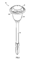
- FIG. 1 shows a side view of a traditional ground based pathway/landscape light 1 with light source 20 including a centrally located cluster of closely spaced LEDS.
- the central light source is located on a bottom facing surface 12 underneath a cover 10 .
- An upper end of a light shade lens 30 is also attached to the bottom facing mount surface 12 .
- the light shade lens 30 can have a bottom end attached to a ground engaging post 40 that can additionally have a spiked end that is inserted into the ground to support the pathway/landscape light 1 .
- FIG. 2 shows the light emissions on a ground surface using a cluster landscape light source. Users have complained about the undesirable shadow spot effects on the ends of each of the surface striking light beams that are emitted from the cluster based landscape lights.
- FIG. 2 shows the illumination effects create different levels of brightness on the surface being illuminated. Some of the light emissions are extremely bright and harsh while other parts of the light emissions are very dim. As a result of the dark spots and different levels of illumination of brightness, a ground surface may not be adequately illuminated so that walkers using the path will not have enough light to see obstructions in the path.
- a primary objective of the present invention is to provide devices, apparatus, systems and methods of using ground directed pathway and landscape lights with perimeter spaced apart LED (light emitting diode) light sources that eliminate undesirable shadow effects from cluster based light sources.
- a secondary objective of the present invention is to provide devices, apparatus, systems and methods of using ground directed pathway and landscape lights with perimeter spaced apart LED (light emitting diode) light sources that provide softer and more uniform light emissions from cluster based light sources.
- LED light emitting diode
- a third objective of the present invention is to provide devices, apparatus, systems and methods of using ground directed pathway and landscape lights with perimeter spaced apart LED (light emitting diode) light sources that provide at least as much if not a greater amount of emitted light than cluster based light sources.
- LED light emitting diode
- a fourth objective of the present invention is to provide devices, apparatus, systems and methods of using 360 degree emitting surface directed LED (light emitting diode) sources with perimeter spaced apart LED (light emitting diode) light sources that eliminate undesirable shadow effects from cluster based light sources.
- a fifth objective of the present invention is to provide devices, apparatus, systems and methods of using 360 degree emitting surface directed LED (light emitting diode) sources with perimeter spaced apart LED (light emitting diode) light sources with perimeter spaced apart LED (light emitting diode) light sources that provide softer and more uniform light emissions from cluster based light sources.
- a sixth objective of the present invention is to provide devices, apparatus, systems and methods of using 360 degree emitting surface directed LED (light emitting diode) sources with perimeter spaced apart LED (light emitting diode) light sources that provide at least as much if not a greater amount of emitted light than cluster based light sources.
- a novel ground directed pathway light can include a mount having a front surface with a width and a length and a midportion therebetween, and a perimeter edge about the mount, a plurality of LEDs (light emitting diodes) spaced apart along the perimeter edge of the front surface of the mount arranged in a equally spaced apart configuration, a ground based engaging post attached to the light which extends downward from a midportion of the front surface of the mount, and a power source for providing power to simultaneously illuminate each of the plurality of LEDs directed toward a ground surface.
- LEDs light emitting diodes
- the light can have a light shade lens having an upper end and a bottom end, the upper end attached to the front surface of the mount, and the ground based engaging post attached to the bottom end of the light shade lens.
- the light can also have a single LED attached to the midportion of the mount, the single LED being equally spaced from each of the plurality of LEDs.
- the mount can be a disc shape with the LEDS located along the perimeter edge of the disc shape.
- the LEDs can be arranged in a triangular configuration about the perimeter edge of the disc shape. Three of the LEDs can be arranged in each of the three corners of the triangular configuration about the perimeter edge of the disc shape.
- LEDs can be arranged in a square configuration about the perimeter edge of the disc shape.
- Four of the LEDs can be arranged in each of the four corners of the square configuration about the perimeter edge of the disc shape.
- At least four or more of the LEDs can be arranged in a midportion along each leg of the square configuration about the perimeter edge of the disc shape.
- the LEDs can be arranged in a hexagon configuration about the perimeter edge of the disc shape. Five of the LEDs can be arranged in each corner of the hexagon configuration about the perimeter edge of the disc shape.
- the mount can have a rectangular shape with the LEDS located along the perimeter edge of the rectangular shape.
- the mount can have a square shape with the LEDS located along the perimeter edge of the square shape.
- the mount can have a triangular shape with the LEDS located along the perimeter edge of the triangular shape.
- the mount can have a hexagon shape with the LEDS located along the perimeter edge of the hexagon shape.
- the power source for the light can be a low voltage electrically connected power supply.
- the power source for the light can be a solar powered connected power supply.
- a ground directed pathway light can include a mount having a front surface with a width and a length and a midportion therebetween, and a perimeter edge about the mount, an LED (light emitting diode) positioned adjacent to a midportion of the front surface of the mount, an optical fiber having a portion circumferentially about the LED light source, a ground based engaging post attached to the light which extends downward from a midportion of the front surface of the mount, and a power source for providing power to simultaneously illuminate the LED and optical fiber which directs light toward a ground surface.
- LED light emitting diode
- the ground directed pathway light can include a light shade lens having an upper end and a bottom end, the upper end attached to the front surface of the mount, and the ground based engaging post attached to the bottom end of the light shade lens.
- the optical fiber can be attached to the front surface of the mount outside of the upper end of the light shade lens.
- the optical fiber can be attached to the front surface of the mount inside of the upper end of the light shade lens.
- the mount can be a disc shape with the LED located adjacent a center location of the disc shape, and the optical fiber is located along the perimeter edge of the disc shape.
- the ground directed pathway light can include a light shade lens having an upper end and a bottom end, the upper end attached to the front surface of the mount, and the ground based engaging post attached to the bottom end of the light shade lens.
- the optical fiber can be attached to the front surface of the mount outside of the upper end of the light shade lens.
- the optical fiber can be attached to the front surface of the mount inside of the upper end of the light shade lens.
- the power source can be a low voltage electrically connected power supply.
- the power source can be a solar powered connected power supply.
- a ground directed landscape light can include a mount having a front surface with a diameter and a midportion therebetween, and a perimeter edge about the mount, a first optical fiber arranged in a ring configuration adjacent to the perimeter edge, a ground based engaging post attached to the light which extends downward from a midportion of the front surface of the mount, a light shade lens having an upper end and a bottom end, the upper end attached to the front surface of the mount, and the ground based engaging post attached to the bottom end of the light shade lens, and a power source for providing power to illuminate the optical fiber which directs light toward a ground surface.
- the mount can be a disc shape.
- the optical fiber can be attached to the front surface of the mount outside of the upper end of the light shade lens.
- the optical fiber can be attached to the front surface of the mount inside of the upper end of the light shade lens.
- the power source can be a low voltage electrically connected power supply.
- the power source can be a solar powered connected power supply.
- the ground directed landscape light can include an LED (light emitting diode) positioned adjacent to a midportion of the front surface of the mount.
- the ground directed landscape light can include a plurality of LEDS attached to the disc adjacent to the midportion of the front surface of the mount.
- the ground directed landscape light can include a second optical fiber arranged in a ring configuration, with the first optical fiber positioned inside of the light shade lens, and the second optical fiber positioned outside of the light shade lens.
- FIG. 1 is a prior art view showing the light emissions on a ground surface using a cluster landscape light source with ground engaging post.
- FIG. 2 shows the light emissions on a ground surface using a pathway and landscape light with the novel perimeter located spaced apart LED light sources.
- FIG. 3 is a perspective upper front exterior view of the novel pathway/landscape light with ground engaging post.
- FIG. 4 is a perspective lower front exterior view of the light of FIG. 3 .
- FIG. 5 is a bottom cross-sectional view of the light of FIG. 4 along arrows 5 Y.
- FIG. 6 is another bottom view of the mount of FIG. 5 without the light shade lens and without the ground engaging post.
- FIG. 7 is a side view of the novel light 100 showing the direction of beams emitting from the perimeter located LEDs.
- FIG. 8 shows light emissions on a ground surface using the novel pathway/landscape light of FIGS. 3-7 .
- FIG. 9 is a bottom view of another embodiment of a rectangular configuration of LEDs.
- FIG. 10 is a bottom view of another embodiment of a hexagon configuration of LEDs.
- FIG. 11 is a bottom view of an embodiment with a circular optical fiber arranged about a centrally located LED (light emitting diode) in a pathway/landscape light.
- FIG. 12 is a perspective exterior view of the pathway/landscape light of FIG. 11 .
- FIG. 3 is a perspective upper front exterior view of the novel pathway/landscape light 100 with ground engaging post 40 .
- FIG. 4 is a perspective lower front exterior view of the light 100 of FIG. 3 .
- FIG. 5 is a bottom cross-sectional view of the light 100 of FIG. 4 along arrows 5 Y.
- FIG. 6 is another bottom view of the mount 110 of FIG. 5 without the light shade lens 30 and without the ground engaging post 40 .
- the novel embodiment can use well known drive circuits to operate the plurality of LEDs, such as those described in U.S. Pat. Nos. 4,866,430 to Chek; 7,559,674 to He et al.; 7,021,787 to Kuelbs (column 10) and U.S. Published Patent Application 2010/0084985 to Woytowitz, which are all incorporated by reference.
- the pathway/landscape light can be powered by low voltage.
- the pathway/landscape light can be solar powered where a battery is solar charged during the day to run the LEDs after dark.
- the light shade lens 30 can have an upper end attached to a lower facing surface 110 of the mount, and a bottom end attached to a ground engaging post 40 .
- the light shade lens 30 can have a generally upside down dome shape.
- the light shade lens 30 can have a generally cylindrical shape.
- the light shade lens 30 can have a generally tubular shape with the upper end having a wider diameter than the bottom end.
- the light shade lens 30 can be clear glass or plastic, and/or have etched patterns, and the like, where light passing through the lens 30 and/or reflecting and/or refracting with the lens 30 can cause prism effects that result in expanding light beam emissions therefrom.
- the light shade lens 30 can have upper edges attached to the mount surface 110 inside the perimeter arrangement of a plurality of LEDS 120 .
- the light shade lens 30 can have upper edges attached to the mount surface 110 outside the perimeter arrangement of the plurality of LEDS 120 .
- the mount 110 with lower surface can have a disc shape, with the plurality of LEDs 120 arranged in a triangular arrangement, with three LEDs 122 , 124 , 126 equally spaced apart about the perimeter of the mount surface 110 .
- the LEDS can be arranged to each be approximately 3.7 inches apart from one another.
- the LEDS 122 , 124 , 126 can be spaced up to approximately 5 inches apart from one another on the approximately 5 inch diameter mount surface 110 .
- three LEDs 122 , 124 , 126 can be located in each of the three corners of the triangular arrangement. Additional LEDs can be located in midportions along each of the three legs of the triangular arrangement so that all LEDs remain equally spaced apart from one another.
- An additional version of the embodiment 100 can include a centrally located single LED 129 in the disc shaped mount surface 110 , where the central LED 129 is located equally distant from the other LEDs 122 , 124 , 126 .
- FIG. 7 is a side view of the novel light 100 showing the direction of beams emitting from the perimeter located LEDs 122 , 124 ( 126 is not shown) and centrally located LED 129 .
- FIG. 8 shows light emissions on a ground surface using the novel pathway/landscape light of FIGS. 3-7 .
- the light beams striking a ground surface do not have the dark spots and effects that exist with the prior art.
- the emitted light beams have a generally uniform brightness throughout each of the beams creating a more aesthetic and desirable effect, as well as more thoroughly illuminate an entire ground surface in 360 degrees than the prior art.
- FIG. 9 is a bottom view of another embodiment 200 of a rectangular configuration of LEDs.
- this embodiment 200 there can be 4 LEDS each located about all 4 corners of a square configuration.
- An additional central located LED can be optionally located in a mid portion of the mount surface 210 .
- Each the 4 LEDs can be located between approximately 3 inches to approximately 5 inches apart from one another, where the LEDs are equally spaced apart from one another. Additional LEDs can be located on each leg of the square between each of the corner located LEDs.
- FIG. 10 is a bottom view of another embodiment 300 of a hexagon configuration of LEDs.
- this embodiment 300 there can be 5 LEDS each located about all 5 corners of a hexagon configuration.
- An additional central located LED can be optionally located in a mid portion of the mount surface 310 .
- Each the 5 LEDs can be located between approximately 2.5 inches to approximately 5 inches apart from one another, where the LEDs are equally spaced apart from one another. Additional LEDs can be located on each leg of the hexagon between each of the corner located LEDs.
- FIG. 11 is a bottom view of another embodiment 400 with a circular optical fiber 430 arranged about a centrally located LED (light emitting diode) 420 in a pathway/landscape light.
- FIG. 12 is a perspective exterior view of the pathway/landscape light 400 of FIG. 11 .
- the pathway/landscape light 400 can include similar features to the previous embodiment which includes a cover with lower hanging perimeter edge 405 , and a mount surface 410 for supporting the light sources thereon.
- a single LED (light emitting diode) 420 can be mounted adjacent to a center point of the disc shaped mount 410 .
- An optical fiber 430 can be arranged in a ring shape about a perimeter edge of the disc shaped mount 410 , and have an input end 434 and outer end 438 .
- the optical fiber can be illuminated by the central LED 420 which can illuminate the surrounding light shade 440 , which then illuminates the optical fiber 430 .
- the optical fiber 430 can be illuminated at the input end 434 by a separate light source 432 , such as another LED, or by light being directed into the input end 434 by the centrally located LED light source 420 .
- a separate light source 432 such as another LED
- the embodiment shown in FIG. 12 has the optical fiber 430 mounted in a ring configuration about the exterior of the base portion of the light shade 440 .
- the optical fiber 430 can be mounted along the perimeter of the light shade 440 inside of the base 442 of the light shade 440 .
- two ring configured optical fibers can be used, with one mounted inside of the base of the light shade lens, and the other mounted outside of the light shade lens.
- the bottom 448 of the light shade lens 440 can be attached to a mounting post that has a lower ground engaging end.
- FIGS. 11-12 shows a single central LED light source 420
- the invention can be practiced with a cluster of LEDs or with spaced apart LEDs as shown and described in the previous embodiments.
- the invention can be practiced with a single optical fiber arranged in a ring shaped configuration about the perimeter edge of the mount of the light without a centrally located LED light source.
- the novel pathway/landscape light 400 can be powered by low voltage power supplies wired to a household power supply and/or be solar powered, along with a battery for allowing the light 400 to be illuminated at night.
- mounts are shown and described as disc shape, the invention can use other mount shapes, such as but not limited to rectangular shaped, square shaped, triangular shaped, hexagon shaped and the like. Other shapes can be used.
- the preferred embodiment shows and describes ground based pathway/landscape lighting using LEDS with or without an optical fiber ring
- the invention can be used with other type of lights that can use 360 degree emitting surface directed LED (light emitting diode) sources with perimeter spaced apart LED (light emitting diode) light sources, where the other types of surfaces to be illuminated such as but not limited to walls, ceilings, and the like.
- the preferred embodiment shows and describes the light source has having a central ground based stake underneath the downwardly directed light source
- the invention can be used with other types of light sources that do not require the central mounting stake, such as but not limited to spotlights, and the like.
Abstract
Pathway and landscape lights, in particular to devices, apparatus, systems and methods of using ground directed pathway and landscape lights with a single or perimeter spaced apart LED (light emitting diode) light sources on a disc mount, with or without an optical fiber arranged in a ring pattern about a perimeter edge of the mount. A light shade lens can have an upper end attached to the lower face of the disc mount, and a bottom end attached to a ground engaging post, so the light emitted from the mount is directed in a 360 degree outwardly expanding direction expanding outward on the ground surface where the ground engaging post is in the center of the 360 degree expanding illumination. A low voltage power source can be used. Alternatively, the light can be solar powered. The light forms uniform light beam emissions without shadow spots effects.
Description
This invention is a Continuation-In-Part of U.S. patent application Ser. No. 13/229,307 filed Sep. 9, 2011, the entire disclosure of which is incorporated by reference in its' entirety.
This invention relates to pathway and landscape lights, in particular to devices, apparatus, systems and methods of using ground directed pathway and landscape lights with a ring configured optical fiber which directs light emissions from a centrally located LED (light emitting diode) light source.
Pathway and landscape lighting are known for providing light sources for gardens, walkways, and the like. LEDS (light emitting diodes) have become increasingly popular over the years as a light source since the LEDs have become more cost effective as well as provide for low power consumption and longer life over standard light bulbs, and the like. However, a single LED is still known to emit low levels of light which are impractical for providing sufficient light for gardens and walkways.
The prior art has used clusters of LED (light emitting diodes) together to generate light in pathway and landscape lighting. See for example, U.S. Pat. Nos. D574,532 to Lee et al., 7,204,608 to Beeman et al. and 7,021,787 to Kuelbs (column 10).
However, there are additional problems with the cluster based prior art. FIG. 1 shows a side view of a traditional ground based pathway/landscape light 1 with light source 20 including a centrally located cluster of closely spaced LEDS. The central light source is located on a bottom facing surface 12 underneath a cover 10. An upper end of a light shade lens 30 is also attached to the bottom facing mount surface 12. The light shade lens 30 can have a bottom end attached to a ground engaging post 40 that can additionally have a spiked end that is inserted into the ground to support the pathway/landscape light 1.
Additionally, users have complained about the light emissions having different levels of illumination on the ground with parts of the light beams. FIG. 2 shows the illumination effects create different levels of brightness on the surface being illuminated. Some of the light emissions are extremely bright and harsh while other parts of the light emissions are very dim. As a result of the dark spots and different levels of illumination of brightness, a ground surface may not be adequately illuminated so that walkers using the path will not have enough light to see obstructions in the path.
Attempts have been made to use other type of arrangements of LEDs for pathways and walkways. See for example, U.S. Patent Application Publication 2006/0203471 to Hodges et al.; 2005/002183 to Wardzala. Hodges is limited to a single linear line of LEDs that projects a line of light. Wardzal uses a ring of LEDs to emit light in a horizontal radial direction. None of the known prior art uses LEDs to direct light in beneath a dome lens covered pathway and landscape light source, where the light is intended to be emitted in a 360 degree direction from the pathway/landscape light. None of the prior art would solve the problem of eliminating shadow effects and different levels of brightness in the light emissions being generated therefrom.
Thus, the need exists for solutions to the above problems with the prior art.
A primary objective of the present invention is to provide devices, apparatus, systems and methods of using ground directed pathway and landscape lights with perimeter spaced apart LED (light emitting diode) light sources that eliminate undesirable shadow effects from cluster based light sources.
A secondary objective of the present invention is to provide devices, apparatus, systems and methods of using ground directed pathway and landscape lights with perimeter spaced apart LED (light emitting diode) light sources that provide softer and more uniform light emissions from cluster based light sources.
A third objective of the present invention is to provide devices, apparatus, systems and methods of using ground directed pathway and landscape lights with perimeter spaced apart LED (light emitting diode) light sources that provide at least as much if not a greater amount of emitted light than cluster based light sources.
A fourth objective of the present invention is to provide devices, apparatus, systems and methods of using 360 degree emitting surface directed LED (light emitting diode) sources with perimeter spaced apart LED (light emitting diode) light sources that eliminate undesirable shadow effects from cluster based light sources.
A fifth objective of the present invention is to provide devices, apparatus, systems and methods of using 360 degree emitting surface directed LED (light emitting diode) sources with perimeter spaced apart LED (light emitting diode) light sources with perimeter spaced apart LED (light emitting diode) light sources that provide softer and more uniform light emissions from cluster based light sources.
A sixth objective of the present invention is to provide devices, apparatus, systems and methods of using 360 degree emitting surface directed LED (light emitting diode) sources with perimeter spaced apart LED (light emitting diode) light sources that provide at least as much if not a greater amount of emitted light than cluster based light sources.
A novel ground directed pathway light, can include a mount having a front surface with a width and a length and a midportion therebetween, and a perimeter edge about the mount, a plurality of LEDs (light emitting diodes) spaced apart along the perimeter edge of the front surface of the mount arranged in a equally spaced apart configuration, a ground based engaging post attached to the light which extends downward from a midportion of the front surface of the mount, and a power source for providing power to simultaneously illuminate each of the plurality of LEDs directed toward a ground surface.
The light can have a light shade lens having an upper end and a bottom end, the upper end attached to the front surface of the mount, and the ground based engaging post attached to the bottom end of the light shade lens.
The light can also have a single LED attached to the midportion of the mount, the single LED being equally spaced from each of the plurality of LEDs.
The mount can be a disc shape with the LEDS located along the perimeter edge of the disc shape. The LEDs can be arranged in a triangular configuration about the perimeter edge of the disc shape. Three of the LEDs can be arranged in each of the three corners of the triangular configuration about the perimeter edge of the disc shape.
Four of the LEDs can be arranged in a square configuration about the perimeter edge of the disc shape. Four of the LEDs can be arranged in each of the four corners of the square configuration about the perimeter edge of the disc shape.
At least four or more of the LEDs can be arranged in a midportion along each leg of the square configuration about the perimeter edge of the disc shape.
The LEDs can be arranged in a hexagon configuration about the perimeter edge of the disc shape. Five of the LEDs can be arranged in each corner of the hexagon configuration about the perimeter edge of the disc shape.
The mount can have a rectangular shape with the LEDS located along the perimeter edge of the rectangular shape. The mount can have a square shape with the LEDS located along the perimeter edge of the square shape. The mount can have a triangular shape with the LEDS located along the perimeter edge of the triangular shape. The mount can have a hexagon shape with the LEDS located along the perimeter edge of the hexagon shape.
The power source for the light can be a low voltage electrically connected power supply. The power source for the light can be a solar powered connected power supply.
A ground directed pathway light, can include a mount having a front surface with a width and a length and a midportion therebetween, and a perimeter edge about the mount, an LED (light emitting diode) positioned adjacent to a midportion of the front surface of the mount, an optical fiber having a portion circumferentially about the LED light source, a ground based engaging post attached to the light which extends downward from a midportion of the front surface of the mount, and a power source for providing power to simultaneously illuminate the LED and optical fiber which directs light toward a ground surface.
The ground directed pathway light can include a light shade lens having an upper end and a bottom end, the upper end attached to the front surface of the mount, and the ground based engaging post attached to the bottom end of the light shade lens.
The optical fiber can be attached to the front surface of the mount outside of the upper end of the light shade lens. The optical fiber can be attached to the front surface of the mount inside of the upper end of the light shade lens.
The mount can be a disc shape with the LED located adjacent a center location of the disc shape, and the optical fiber is located along the perimeter edge of the disc shape.
The ground directed pathway light can include a light shade lens having an upper end and a bottom end, the upper end attached to the front surface of the mount, and the ground based engaging post attached to the bottom end of the light shade lens.
The optical fiber can be attached to the front surface of the mount outside of the upper end of the light shade lens.
The optical fiber can be attached to the front surface of the mount inside of the upper end of the light shade lens.
The power source can be a low voltage electrically connected power supply. The power source can be a solar powered connected power supply.
A ground directed landscape light can include a mount having a front surface with a diameter and a midportion therebetween, and a perimeter edge about the mount, a first optical fiber arranged in a ring configuration adjacent to the perimeter edge, a ground based engaging post attached to the light which extends downward from a midportion of the front surface of the mount, a light shade lens having an upper end and a bottom end, the upper end attached to the front surface of the mount, and the ground based engaging post attached to the bottom end of the light shade lens, and a power source for providing power to illuminate the optical fiber which directs light toward a ground surface.
The mount can be a disc shape. The optical fiber can be attached to the front surface of the mount outside of the upper end of the light shade lens. The optical fiber can be attached to the front surface of the mount inside of the upper end of the light shade lens. The power source can be a low voltage electrically connected power supply. The power source can be a solar powered connected power supply.
The ground directed landscape light can include an LED (light emitting diode) positioned adjacent to a midportion of the front surface of the mount. The ground directed landscape light can include a plurality of LEDS attached to the disc adjacent to the midportion of the front surface of the mount.
The ground directed landscape light can include a second optical fiber arranged in a ring configuration, with the first optical fiber positioned inside of the light shade lens, and the second optical fiber positioned outside of the light shade lens.
Further objects and advantages of this invention will be apparent from the following detailed description of the presently preferred embodiments which are illustrated schematically in the accompanying drawings.
Before explaining the disclosed embodiments of the present invention in detail it is to be understood that the invention is not limited in its applications to the details of the particular arrangements shown since the invention is capable of other embodiments. Also, the terminology used herein is for the purpose of description and not of limitation.
This invention is a Continuation-In-Part of U.S. patent application Ser. No. 13/229,307 filed Sep. 9, 2011, which is incorporated by reference.
- 1. prior art version of pathway light
- 10. cover of pathway light
- 12. bottom facing mount surface
- 20. centrally located cluster of LEDs
- 30. light shade lens
- 40. ground engaging post
- 100. first embodiment of plurality of perimeter configured LEDS
- 110. bottom surface of mount
- 120. plurality of perimeter attached LEDs.
- 122. first LED
- 124. second LED
- 126. third LED
- 129. centrally located LED
- 200. square and rectangular arrangement of LEDs
- 210. bottom surface of the mount
- 300. hexagon arrangement of LEDs
- 310. bottom surface of the mount
- 400. Optical Fiber Ring about single or plural LEDS
- 405. lower hanging perimeter edge of light cover
- 410. bottom surface of mount
- 420. centrally located LED
- 430. optical fiber in ring configuration.
- 432. input for optical fiber
- 434. input end of optical fiber
- 438. outer end of optical fiber
- 440. light shade lens
- 442. base of light shade lens
- 450. mounting post
The pathway/landscape light can be powered by low voltage. Alternatively, the pathway/landscape light can be solar powered where a battery is solar charged during the day to run the LEDs after dark.
Referring to FIGS. 3-6 , the light shade lens 30 can have an upper end attached to a lower facing surface 110 of the mount, and a bottom end attached to a ground engaging post 40. The light shade lens 30 can have a generally upside down dome shape. Alternatively, the light shade lens 30 can have a generally cylindrical shape. Still furthermore, the light shade lens 30 can have a generally tubular shape with the upper end having a wider diameter than the bottom end. The light shade lens 30 can be clear glass or plastic, and/or have etched patterns, and the like, where light passing through the lens 30 and/or reflecting and/or refracting with the lens 30 can cause prism effects that result in expanding light beam emissions therefrom.
With the invention, the light shade lens 30 can have upper edges attached to the mount surface 110 inside the perimeter arrangement of a plurality of LEDS 120. Alternatively, the light shade lens 30 can have upper edges attached to the mount surface 110 outside the perimeter arrangement of the plurality of LEDS 120.
The mount 110 with lower surface can have a disc shape, with the plurality of LEDs 120 arranged in a triangular arrangement, with three LEDs 122, 124, 126 equally spaced apart about the perimeter of the mount surface 110. With approximately 5 inch diameter mount surface 110, the LEDS can be arranged to each be approximately 3.7 inches apart from one another. Additionally, the LEDS 122, 124, 126 can be spaced up to approximately 5 inches apart from one another on the approximately 5 inch diameter mount surface 110. With the triangular arrangement, three LEDs 122, 124, 126 can be located in each of the three corners of the triangular arrangement. Additional LEDs can be located in midportions along each of the three legs of the triangular arrangement so that all LEDs remain equally spaced apart from one another.
An additional version of the embodiment 100 can include a centrally located single LED 129 in the disc shaped mount surface 110, where the central LED 129 is located equally distant from the other LEDs 122, 124, 126.
Referring to FIGS. 11-12 , the pathway/landscape light 400 can include similar features to the previous embodiment which includes a cover with lower hanging perimeter edge 405, and a mount surface 410 for supporting the light sources thereon. Here, a single LED (light emitting diode) 420 can be mounted adjacent to a center point of the disc shaped mount 410. An optical fiber 430 can be arranged in a ring shape about a perimeter edge of the disc shaped mount 410, and have an input end 434 and outer end 438. The optical fiber can be illuminated by the central LED 420 which can illuminate the surrounding light shade 440, which then illuminates the optical fiber 430.
Alternatively, the optical fiber 430 can be illuminated at the input end 434 by a separate light source 432, such as another LED, or by light being directed into the input end 434 by the centrally located LED light source 420.
The embodiment shown in FIG. 12 has the optical fiber 430 mounted in a ring configuration about the exterior of the base portion of the light shade 440. Alternatively, the optical fiber 430 can be mounted along the perimeter of the light shade 440 inside of the base 442 of the light shade 440. Still furthermore, two ring configured optical fibers can be used, with one mounted inside of the base of the light shade lens, and the other mounted outside of the light shade lens.
The bottom 448 of the light shade lens 440 can be attached to a mounting post that has a lower ground engaging end.
While the embodiment in FIGS. 11-12 shows a single central LED light source 420, the invention can be practiced with a cluster of LEDs or with spaced apart LEDs as shown and described in the previous embodiments.
Alternatively, the invention can be practiced with a single optical fiber arranged in a ring shaped configuration about the perimeter edge of the mount of the light without a centrally located LED light source.
Similar to the other embodiments, the novel pathway/landscape light 400 can be powered by low voltage power supplies wired to a household power supply and/or be solar powered, along with a battery for allowing the light 400 to be illuminated at night.
Although the mounts are shown and described as disc shape, the invention can use other mount shapes, such as but not limited to rectangular shaped, square shaped, triangular shaped, hexagon shaped and the like. Other shapes can be used.
Although the preferred embodiment shows and describes ground based pathway/landscape lighting using LEDS with or without an optical fiber ring, the invention can be used with other type of lights that can use 360 degree emitting surface directed LED (light emitting diode) sources with perimeter spaced apart LED (light emitting diode) light sources, where the other types of surfaces to be illuminated such as but not limited to walls, ceilings, and the like.
Although the preferred embodiment shows and describes the light source has having a central ground based stake underneath the downwardly directed light source, the invention can be used with other types of light sources that do not require the central mounting stake, such as but not limited to spotlights, and the like.
While the invention has been described, disclosed, illustrated and shown in various terms of certain embodiments or modifications which it has presumed in practice, the scope of the invention is not intended to be, nor should it be deemed to be, limited thereby and such other modifications or embodiments as may be suggested by the teachings herein are particularly reserved especially as they fall within the breadth and scope of the claims here appended.
Claims (20)
1. A ground directed pathway light, comprising:
a horizontal mount having a downwardly facing front planar surface with a width and a length and a midportion therebetween, and a perimeter edge about the planar surface of the mount, the mount having an upwardly facing rear surface on an opposite side of the mount;
an LED (light emitting diode) positioned adjacent to and attached to a midportion of the downwardly facing front planar surface of the mount;
an optical fiber having a ring shape circumferentially about the LED light source, the optical fiber being attached to the downwardly facing front planar surface of the mount;
a ground based engaging post having an upper end and a lower end, the upper end attached to the light, and the lower end of the post extending downward from a midportion of the downwardly facing front planar surface of the mount, the lower end of the post adapted for engagement into a ground surface; and
a power source for providing power to simultaneously illuminate the LED and optical fiber which directs light toward the ground surface, wherein uniform light emissions without undesirable shadow effects are emitted from the LED and ring shaped optical fiber in approximately 360 degree directions toward the ground surface around the post.
2. The ground directed pathway light of claim 1 , further comprising:
a light shade lens having an upper end and a bottom end, the upper end attached to the downwardly facing front planar surface of the mount, and the ground based engaging post attached to the bottom end of the light shade lens.
3. The ground directed pathway light of claim 2 , wherein the optical fiber is attached to the downwardly facing front planar surface of the mount outside of the upper end of the light shade lens.
4. The ground directed pathway light of claim 2 , wherein the optical fiber is attached to the downwardly facing front planar surface of the mount inside of the upper end of the light shade lens.
5. The ground directed pathway light of claim 1 , wherein the mount includes a disc shape with the LED located adjacent a center location on the downwardly facing front planar surface of the disc shape, and the optical fiber is located along the perimeter edge on the downwardly facing front planar surface of the disc shape.
6. The ground directed pathway light of claim 5 , further comprising:
a light shade lens having an upper end and a bottom end, the upper end attached to the downwardly facing front planar surface of the disc shape, and the ground based engaging post is attached to the bottom end of the light shade lens.
7. The ground directed pathway light of claim 6 , wherein the optical fiber is attached to the downwardly facing front planar surface of the disc shape outside of the upper end of the light shade lens.
8. The ground directed pathway light of claim 6 , wherein the optical fiber is attached to the downwardly facing front planar surface of the disc shape inside of the upper end of the light shade lens.
9. The ground directed pathway light of claim 1 , wherein the power source is a low voltage electrically connected power supply.
10. The ground directed pathway light of claim 1 , wherein the power source is a solar powered connected power supply.
11. A ground directed landscape light, comprising:
a mount having a downwardly facing front planar surface with a diameter and a midportion therebetween, and a perimeter edge about the mount, the mount having an upwardly facing rear surface on an opposite side of the mount;
a first optical fiber arranged in a ring configuration adjacent to the perimeter edge attached to the downwardly facing front planar surface of the mount;
a ground based engaging post having an upper end attached to the light, and a lower end extending extends downward from a midportion of the downwardly facing front planar surface of the mount;
a light shade lens having an upper end and a bottom end, the upper end attached to the downwardly facing front planar surface of the mount, and the upper end of the ground based engaging post attached to the bottom end of the light shade lens, with the lower end of the post adapted for engagement into a ground surface; and
a power source for providing power to illuminate the optical fiber which directs light toward the ground surface.
12. The ground directed landscape light of claim 11 , wherein the mount includes:
a disc shape with the first optical fiber attached to the downwardly facing front planar surface of the disc shape.
13. The ground directed landscape light of claim 11 , wherein the optical fiber is attached to the downwardly facing front planar surface of the disc shape outside of the upper end of the light shade lens.
14. The ground directed landscape light of claim 11 , wherein the optical fiber is attached to the downwardly facing front planar surface of the disc shape t inside of the upper end of the light shade lens.
15. The ground directed landscape light of claim 11 , wherein the power source is a low voltage electrically connected power supply.
16. The ground directed landscape light of claim 11 , wherein the power source is a solar powered connected power supply.
17. The ground directed landscape light of claim 11 , further comprising:
an LED (light emitting diode) positioned adjacent to a midportion on the downwardly facing front surface of the mount.
18. The ground directed landscape light of claim 17 , further comprising:
a plurality of LEDS attached to the mount adjacent to the midportion attached on the downwardly facing front planar surface of the mount.
19. The ground directed landscape light of claim 11 , further comprising:
a second optical fiber arranged in a ring configuration attached to the downwardly facing front planar surface of the mount, with the first optical fiber positioned inside of the light shade lens, and the second optical fiber positioned outside of the light shade lens.
20. The ground directed landscape light of claim 19 , further comprising:
an LED (light emitting diode) positioned adjacent to a midportion attached on the downwardly facing front planar surface of the mount.
Priority Applications (1)
| Application Number | Priority Date | Filing Date | Title |
|---|---|---|---|
| US13/315,578 US8632234B1 (en) | 2011-09-09 | 2011-12-09 | LED and fiber optic ring pathway light |
Applications Claiming Priority (2)
| Application Number | Priority Date | Filing Date | Title |
|---|---|---|---|
| US13/229,307 US8602585B1 (en) | 2011-09-09 | 2011-09-09 | Pathway and landscape lights with perimeter spaced apart LEDs (light emitting diodes) |
| US13/315,578 US8632234B1 (en) | 2011-09-09 | 2011-12-09 | LED and fiber optic ring pathway light |
Related Parent Applications (1)
| Application Number | Title | Priority Date | Filing Date |
|---|---|---|---|
| US13/229,307 Continuation-In-Part US8602585B1 (en) | 2011-09-09 | 2011-09-09 | Pathway and landscape lights with perimeter spaced apart LEDs (light emitting diodes) |
Publications (1)
| Publication Number | Publication Date |
|---|---|
| US8632234B1 true US8632234B1 (en) | 2014-01-21 |
Family
ID=49919198
Family Applications (1)
| Application Number | Title | Priority Date | Filing Date |
|---|---|---|---|
| US13/315,578 Active 2031-11-17 US8632234B1 (en) | 2011-09-09 | 2011-12-09 | LED and fiber optic ring pathway light |
Country Status (1)
| Country | Link |
|---|---|
| US (1) | US8632234B1 (en) |
Cited By (20)
| Publication number | Priority date | Publication date | Assignee | Title |
|---|---|---|---|---|
| CN104154473A (en) * | 2014-07-30 | 2014-11-19 | 重庆名亨科技有限公司 | Shadowless LED lighting system for classroom |
| US20170122550A1 (en) * | 2015-11-04 | 2017-05-04 | Twin-Star International, Inc. | Lantern with heater |
| USD834233S1 (en) | 2018-04-13 | 2018-11-20 | E. Mishan & Sons, Inc. | Rock disk light |
| US10178747B1 (en) | 2017-01-18 | 2019-01-08 | Chien Luen Industries Co., Ltd., Inc. | System for landscape lighting customization and communication |
| US20190049096A1 (en) * | 2017-08-10 | 2019-02-14 | Volt, LLC | Landscape lighting assembly having a cylindrical gobo |
| USD841213S1 (en) * | 2017-11-02 | 2019-02-19 | Zhongshan Yinghao Solar Technology Co., Ltd | Solar energy lawn lamp |
| USD841879S1 (en) | 2018-09-06 | 2019-02-26 | E. Mishan & Sons, Inc. | Swivel disk light |
| USD842522S1 (en) | 2018-09-04 | 2019-03-05 | E. Mishan & Sons, Inc. | Rock disk light |
| USD842523S1 (en) | 2018-09-04 | 2019-03-05 | E. Mishan & Sons, Inc. | Rock disk light |
| USD844878S1 (en) * | 2017-10-25 | 2019-04-02 | Shenzhen City Yuyiyuan Technology Co., Ltd. | Landscape light |
| US10309590B2 (en) | 2018-09-06 | 2019-06-04 | E. Mishan & Sons, Inc. | Solar disk light with swivel mount |
| US10323829B1 (en) | 2017-07-10 | 2019-06-18 | Chien Luen Industries Co., Ltd., Inc. | Multi-beam angle spotlight |
| DE102018002191A1 (en) * | 2018-03-17 | 2019-09-19 | Hess GmbH Licht + Form | lighting device |
| USD864452S1 (en) | 2018-02-28 | 2019-10-22 | E. Mishan & Sons, Inc. | Outdoor light |
| US10488002B1 (en) * | 2019-01-03 | 2019-11-26 | Metromax America Corporation | Solar garden light |
| USD898974S1 (en) | 2020-03-27 | 2020-10-13 | E. Mishan & Sons, Inc. | Landscape light |
| USD908253S1 (en) | 2020-06-17 | 2021-01-19 | E. Mishan & Sons, Inc. | Square solar LED light |
| USD950822S1 (en) | 2021-04-12 | 2022-05-03 | E. Mishan & Sons, Inc. | Swivel disk light |
| US11402079B1 (en) | 2020-10-29 | 2022-08-02 | Chien Luen Industries Co., Ltd., Inc. | Landscape lamps with adjustable light modifiers |
| USRE49252E1 (en) | 2018-09-06 | 2022-10-18 | E. Mishan & Sons, Inc. | Solar disk light with swivel mount |
Citations (18)
| Publication number | Priority date | Publication date | Assignee | Title |
|---|---|---|---|---|
| US3777138A (en) * | 1972-06-23 | 1973-12-04 | I Metzler | Post lantern for attachment to structural support member |
| US5226721A (en) | 1992-12-11 | 1993-07-13 | Stokes Dana A | Decorative outdoor light |
| US6357892B1 (en) | 2000-03-28 | 2002-03-19 | Joshua Beadle | Lighting fixture with beam adjustment |
| US6784357B1 (en) * | 2002-02-07 | 2004-08-31 | Chao Hsiang Wang | Solar energy-operated street-lamp system |
| US20050002183A1 (en) | 2003-05-12 | 2005-01-06 | Wardzala Robert W. | Driveway and landscape light with survivability and durability attributes |
| US6874905B1 (en) | 2003-02-19 | 2005-04-05 | Pathway light fixture | |
| US7021787B1 (en) | 2001-11-02 | 2006-04-04 | World Factory, Inc. | Outdoor lighting system |
| US7083315B2 (en) * | 2001-03-26 | 2006-08-01 | Siemens Airfield Solutions | Elevated airfield runway and taxiway edge-lights utilizing light emitting diodes |
| US20060203471A1 (en) | 2005-03-11 | 2006-09-14 | Computerized Security Systems, Inc. | Pathway lighting for door handles |
| US7192155B2 (en) * | 2004-08-31 | 2007-03-20 | Siemens Airfield Solutions | Airfield edge-light utilizing a side-emitting light source |
| US7204608B2 (en) | 2002-07-23 | 2007-04-17 | Beeman Holdings Inc. | Variable color landscape lighting |
| US20080074867A1 (en) * | 2006-09-21 | 2008-03-27 | International Development Corp. | Solar powered outdoor flicker light |
| US7387409B1 (en) | 2006-03-01 | 2008-06-17 | Beadle Joshua Z | Pathway light fixture with interchangeable components |
| USD574532S1 (en) | 2007-05-21 | 2008-08-05 | The Brinkmann Corporation | Solar spotlight |
| US20100084985A1 (en) | 2008-10-02 | 2010-04-08 | Woytowitz Peter J | Low Voltage Outdoor Lighting Power Source and Control System |
| US7841734B2 (en) * | 2008-05-27 | 2010-11-30 | Ruud Lighting, Inc. | LED lighting fixture |
| US8002428B2 (en) * | 2007-10-17 | 2011-08-23 | Lsi Industries, Inc. | Luminaire and methods of use |
| US8382347B2 (en) * | 2009-04-02 | 2013-02-26 | Abl Ip Holding Llc | Light fixture |
-
2011
- 2011-12-09 US US13/315,578 patent/US8632234B1/en active Active
Patent Citations (18)
| Publication number | Priority date | Publication date | Assignee | Title |
|---|---|---|---|---|
| US3777138A (en) * | 1972-06-23 | 1973-12-04 | I Metzler | Post lantern for attachment to structural support member |
| US5226721A (en) | 1992-12-11 | 1993-07-13 | Stokes Dana A | Decorative outdoor light |
| US6357892B1 (en) | 2000-03-28 | 2002-03-19 | Joshua Beadle | Lighting fixture with beam adjustment |
| US7083315B2 (en) * | 2001-03-26 | 2006-08-01 | Siemens Airfield Solutions | Elevated airfield runway and taxiway edge-lights utilizing light emitting diodes |
| US7021787B1 (en) | 2001-11-02 | 2006-04-04 | World Factory, Inc. | Outdoor lighting system |
| US6784357B1 (en) * | 2002-02-07 | 2004-08-31 | Chao Hsiang Wang | Solar energy-operated street-lamp system |
| US7204608B2 (en) | 2002-07-23 | 2007-04-17 | Beeman Holdings Inc. | Variable color landscape lighting |
| US6874905B1 (en) | 2003-02-19 | 2005-04-05 | Pathway light fixture | |
| US20050002183A1 (en) | 2003-05-12 | 2005-01-06 | Wardzala Robert W. | Driveway and landscape light with survivability and durability attributes |
| US7192155B2 (en) * | 2004-08-31 | 2007-03-20 | Siemens Airfield Solutions | Airfield edge-light utilizing a side-emitting light source |
| US20060203471A1 (en) | 2005-03-11 | 2006-09-14 | Computerized Security Systems, Inc. | Pathway lighting for door handles |
| US7387409B1 (en) | 2006-03-01 | 2008-06-17 | Beadle Joshua Z | Pathway light fixture with interchangeable components |
| US20080074867A1 (en) * | 2006-09-21 | 2008-03-27 | International Development Corp. | Solar powered outdoor flicker light |
| USD574532S1 (en) | 2007-05-21 | 2008-08-05 | The Brinkmann Corporation | Solar spotlight |
| US8002428B2 (en) * | 2007-10-17 | 2011-08-23 | Lsi Industries, Inc. | Luminaire and methods of use |
| US7841734B2 (en) * | 2008-05-27 | 2010-11-30 | Ruud Lighting, Inc. | LED lighting fixture |
| US20100084985A1 (en) | 2008-10-02 | 2010-04-08 | Woytowitz Peter J | Low Voltage Outdoor Lighting Power Source and Control System |
| US8382347B2 (en) * | 2009-04-02 | 2013-02-26 | Abl Ip Holding Llc | Light fixture |
Cited By (24)
| Publication number | Priority date | Publication date | Assignee | Title |
|---|---|---|---|---|
| CN104154473A (en) * | 2014-07-30 | 2014-11-19 | 重庆名亨科技有限公司 | Shadowless LED lighting system for classroom |
| US10274188B2 (en) * | 2015-11-04 | 2019-04-30 | Twin-Star International, Inc. | Lantern with heater |
| US20170122550A1 (en) * | 2015-11-04 | 2017-05-04 | Twin-Star International, Inc. | Lantern with heater |
| US10178747B1 (en) | 2017-01-18 | 2019-01-08 | Chien Luen Industries Co., Ltd., Inc. | System for landscape lighting customization and communication |
| US10323829B1 (en) | 2017-07-10 | 2019-06-18 | Chien Luen Industries Co., Ltd., Inc. | Multi-beam angle spotlight |
| US10634315B2 (en) * | 2017-08-10 | 2020-04-28 | Volt, LLC | Landscape lighting assembly having a cylindrical gobo |
| US20190049096A1 (en) * | 2017-08-10 | 2019-02-14 | Volt, LLC | Landscape lighting assembly having a cylindrical gobo |
| USD844878S1 (en) * | 2017-10-25 | 2019-04-02 | Shenzhen City Yuyiyuan Technology Co., Ltd. | Landscape light |
| USD841213S1 (en) * | 2017-11-02 | 2019-02-19 | Zhongshan Yinghao Solar Technology Co., Ltd | Solar energy lawn lamp |
| USD864452S1 (en) | 2018-02-28 | 2019-10-22 | E. Mishan & Sons, Inc. | Outdoor light |
| DE102018002191A1 (en) * | 2018-03-17 | 2019-09-19 | Hess GmbH Licht + Form | lighting device |
| USD834233S1 (en) | 2018-04-13 | 2018-11-20 | E. Mishan & Sons, Inc. | Rock disk light |
| USD838891S1 (en) | 2018-04-13 | 2019-01-22 | E. Mishan & Sons, Inc. | Rock disk light |
| USD842523S1 (en) | 2018-09-04 | 2019-03-05 | E. Mishan & Sons, Inc. | Rock disk light |
| USD842522S1 (en) | 2018-09-04 | 2019-03-05 | E. Mishan & Sons, Inc. | Rock disk light |
| US10309590B2 (en) | 2018-09-06 | 2019-06-04 | E. Mishan & Sons, Inc. | Solar disk light with swivel mount |
| USD841873S1 (en) | 2018-09-06 | 2019-02-26 | E. Mishan & Sons, Inc. | Swivel disk light |
| USD841879S1 (en) | 2018-09-06 | 2019-02-26 | E. Mishan & Sons, Inc. | Swivel disk light |
| USRE49252E1 (en) | 2018-09-06 | 2022-10-18 | E. Mishan & Sons, Inc. | Solar disk light with swivel mount |
| US10488002B1 (en) * | 2019-01-03 | 2019-11-26 | Metromax America Corporation | Solar garden light |
| USD898974S1 (en) | 2020-03-27 | 2020-10-13 | E. Mishan & Sons, Inc. | Landscape light |
| USD908253S1 (en) | 2020-06-17 | 2021-01-19 | E. Mishan & Sons, Inc. | Square solar LED light |
| US11402079B1 (en) | 2020-10-29 | 2022-08-02 | Chien Luen Industries Co., Ltd., Inc. | Landscape lamps with adjustable light modifiers |
| USD950822S1 (en) | 2021-04-12 | 2022-05-03 | E. Mishan & Sons, Inc. | Swivel disk light |
Similar Documents
| Publication | Publication Date | Title |
|---|---|---|
| US8632234B1 (en) | LED and fiber optic ring pathway light | |
| US8602585B1 (en) | Pathway and landscape lights with perimeter spaced apart LEDs (light emitting diodes) | |
| JP5165489B2 (en) | Diffusion lens and light emitting device assembly using the same | |
| US20080304289A1 (en) | LED night light with more than 1 optics means | |
| RU2010153260A (en) | LED STREET LIGHT | |
| US10941909B2 (en) | Luminaire with independently controlled light output | |
| US20220299174A1 (en) | Systems and methods for assembling a light engine | |
| KR101469618B1 (en) | Led lens for flood light of sign board | |
| KR200473336Y1 (en) | Bottom laying led lighting appratus | |
| US9791116B2 (en) | Modular light engine for variable light pattern | |
| US20130250575A1 (en) | LED Retrofit Lighting Fixture | |
| US20160223164A1 (en) | Wall washer lighting system with light emitter, optical lens and reflector | |
| KR100695532B1 (en) | LED diffusion lamp | |
| KR200464527Y1 (en) | Reflection plate of LED lamp equipment | |
| KR100983350B1 (en) | Landscape street light | |
| JP2013045604A (en) | Lighting fixture | |
| KR20090099420A (en) | Reflector and led lamp for streetlight having the same | |
| KR100552927B1 (en) | Led lamp | |
| KR200213230Y1 (en) | Outdoor lighting equipment using optical fiber | |
| KR101334602B1 (en) | LED Image-Pole Light | |
| KR101361261B1 (en) | Lens device for light emitting diode | |
| KR200295125Y1 (en) | Signal light with light emitting diode | |
| JP3173965U (en) | Lighting device | |
| KR200425018Y1 (en) | illumination a lamp | |
| KR100922299B1 (en) | A led lighting fitting easy change light induction diffuser |
Legal Events
| Date | Code | Title | Description |
|---|---|---|---|
| AS | Assignment |
Owner name: CHIEN LUEN INDUSTRIES CO., LTD., INC., FLORIDA Free format text: ASSIGNMENT OF ASSIGNORS INTEREST;ASSIGNORS:LOWE, TIEN S.;VELUTINI, MARK;RIVERA, ELI E.;AND OTHERS;SIGNING DATES FROM 20111206 TO 20111209;REEL/FRAME:027358/0927 |
|
| STCF | Information on status: patent grant |
Free format text: PATENTED CASE |
|
| FPAY | Fee payment |
Year of fee payment: 4 |
|
| MAFP | Maintenance fee payment |
Free format text: PAYMENT OF MAINTENANCE FEE, 8TH YR, SMALL ENTITY (ORIGINAL EVENT CODE: M2552); ENTITY STATUS OF PATENT OWNER: SMALL ENTITY Year of fee payment: 8 |