US8626700B1 - Context aware device execution for simulating neural networks in compute unified device architecture - Google Patents
Context aware device execution for simulating neural networks in compute unified device architecture Download PDFInfo
- Publication number
- US8626700B1 US8626700B1 US13/097,615 US201113097615A US8626700B1 US 8626700 B1 US8626700 B1 US 8626700B1 US 201113097615 A US201113097615 A US 201113097615A US 8626700 B1 US8626700 B1 US 8626700B1
- Authority
- US
- United States
- Prior art keywords
- neurons
- neuron
- fields
- type
- connections
- Prior art date
- Legal status (The legal status is an assumption and is not a legal conclusion. Google has not performed a legal analysis and makes no representation as to the accuracy of the status listed.)
- Expired - Fee Related, expires
Links
Images


Classifications
-
- G—PHYSICS
- G06—COMPUTING; CALCULATING OR COUNTING
- G06N—COMPUTING ARRANGEMENTS BASED ON SPECIFIC COMPUTATIONAL MODELS
- G06N3/00—Computing arrangements based on biological models
- G06N3/02—Neural networks
- G06N3/04—Architecture, e.g. interconnection topology
- G06N3/049—Temporal neural networks, e.g. delay elements, oscillating neurons or pulsed inputs
-
- G—PHYSICS
- G06—COMPUTING; CALCULATING OR COUNTING
- G06N—COMPUTING ARRANGEMENTS BASED ON SPECIFIC COMPUTATIONAL MODELS
- G06N3/00—Computing arrangements based on biological models
- G06N3/02—Neural networks
- G06N3/10—Interfaces, programming languages or software development kits, e.g. for simulating neural networks
Definitions
- the present invention relates generally to Single Instruction Multiple Data (“SIMD”) and Single Instruction Multiple Thread (“SIMT”) architectures and, in particular, processing of neural networks using a SIMD/SIMT architecture.
- SIMD Single Instruction Multiple Data
- SIMT Single Instruction Multiple Thread
- Divergence in a SIMD/SIMT architecture refers to the divergence of two or more processors or threads. Divergence occurs when a set of processors or threads executing simultaneously encounters an instruction and/or data which causes a subset of threads to branch into a different execution path than the other threads. As a result, the threads are no longer synchronized (i.e., executing the same instructions) and can therefore not be run simultaneously on a SIMD/SIMT architecture.
- Embodiments of the invention include a method comprising generating a map file from a type definition associating a neuron or connection with an attribute, the map file configured to allocate a position in a buffer to the attribute and to allocate the position in the buffer to an additional attribute of an additional neuron or connection of a different type, and building executable code from kernel code and the map file.
- FIG. 1 is a processor architecture illustrating hierarchy of elements of a GPU, in accordance with an embodiment of the present invention.
- FIG. 2 is a data structure illustrating individual state vectors corresponding to J, each having all of the fields associated with each type, in accordance with an embodiment of the present invention.
- FIG. 3 is an abstract representation of a matrix data structure used to store state vectors for neurons and/or connections, in accordance with an embodiment of the present invention.
- FIG. 4 is a data structure illustrating vector padding to prevent thread divergence within a warp, in accordance with an embodiment of the present invention.
- FIG. 5 is a flowchart illustrating steps by which a data structure is allocated, in accordance with an embodiment of the present invention.
- FIG. 6 illustrates a schematic representation of interactions between various elements in an executable build process, in accordance with an embodiment of the present invention.
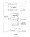
- FIG. 7 is a flowchart illustrating the steps by which executable code is created from kernel code and connection or neuron type definitions, in accordance with an embodiment of the present invention.
- FIG. 8 depicts an example computer system in which embodiments of the present invention may be implemented.
- SIMD architectures including the SIMT architecture provided by the Compute Unified Device Architecture (“CUDA”) developed by NVIDIA C ORPORATION of Santa Clara, Calif.
- CUDA Compute Unified Device Architecture
- Reference to either SIMD or SIMT in this context is therefore intended to describe non-limiting applicability to a wide range of SIMD and other architectures, and is not limited to applications specific to CUDA.
- a neural network operates essentially as a set of discrete elements (neurons) that are connected to one another. Each neuron is typically connected to a small fraction of all the neurons in the network. A set of states and parameters, potentially changing with time, are associated with each neuron and connection. This association can be expressed by saying that each neuron is described by some vector, ⁇ right arrow over (r) ⁇ j , where the subscript identifies the neuron. Similarly, each connection is described by its own vector ⁇ right arrow over (w) ⁇ k where the subscript k identifies the connection.
- each connection is directed. This means that, for each connection, one neuron is designated as the start of the connection (“pre-synaptic neuron”) and the other neuron is designated as the terminal for the connection (“post-synaptic neuron”).
- pre-synaptic neuron one neuron is designated as the start of the connection
- post-synaptic neuron the other neuron is designated as the terminal for the connection
- the pre- and post-synaptic nomenclature is obtained from the neuroscience community, and refers to the fact that biological molecules (neuro-transmitters) travel from the pre-synaptic neuron to the post-synaptic neuron.
- a neural network is therefore defined by the following data:
- R ⁇ right arrow over (r) ⁇ i : i ⁇ 1, 2, . . . , N r ⁇
- W ⁇ right arrow over (w) ⁇ m : m ⁇ 1, 2, . . . N w ⁇
- C ⁇ (i, j, m): m ⁇ 1, 2, . . . , N w ⁇
- N r is the number of neurons in the network and N w is the number of connections.
- R is the set of state vectors describing the neurons.
- W is the set of state vectors describing the connections.
- C is a set of ordered triplets. Each of these triplets describes one connection in the network.
- the first value in this triplet, i specifies the index of the pre-synaptic neuron.
- j is the index of the post-synaptic neuron.
- m is an index which identifies the connection, i.e. m has a unique value for each ordered triplet (i,j,m).
- Each of these indexes corresponds to a state vector ⁇ right arrow over (r) ⁇ i , ⁇ right arrow over (r) ⁇ j , ⁇ right arrow over (w) ⁇ m which contains the states and parameters of the pre-synaptic, post-synaptic and connection respectively.
- Each connection has one weight associated with it.
- a neural network operates by iteratively updating the state vectors for the neurons and connections. Each iteration is referred to as an epoch or time step. At each time step we update the state vector for each neuron j by evaluating some function ⁇ j for that neuron. After updating all neurons, each connection m is updated by evaluating some function g m . Input is provided to the network by allowing the function ⁇ j for some neurons to depend on an input signal ⁇ right arrow over (I) ⁇ .
- I input signal
- the key idea of a neural network is that the connections determine which neurons directly influence the state vectors of other neurons. Furthermore, this interaction is modulated by the state values of that connection, ⁇ right arrow over (w) ⁇ m . This is described in more detail below.
- the state vector for neuron j is updated by executing some function ⁇ j .
- the output of this function is the new value for the neuron's state vector, ⁇ right arrow over (r) ⁇ j .
- This function depends on the current value of the state vector ⁇ right arrow over (r) ⁇ j as well as all connections (and the associated pre-synaptic neuron) for which neuron j is the post-synaptic neuron. We can therefore write the update for neuron j as
- the set C j denotes the set of all pairs of pre-synaptic state vectors ⁇ right arrow over (r) ⁇ i and connection state vectors ⁇ right arrow over (w) ⁇ m for which there exists a connection from neuron i to neuron j.
- the arrow means the value of ⁇ right arrow over (r) ⁇ j is replaced with the result of evaluating ⁇ j .
- the function ⁇ j can be almost any function that satisfies the following constraints.
- the function ⁇ j can only depend on some intermediary values, ⁇ right arrow over (a) ⁇ m , which are a function only of ( ⁇ right arrow over (r) ⁇ i , ⁇ right arrow over (r) ⁇ j , ⁇ right arrow over (w) ⁇ m ) for connection m.
- ⁇ m , ⁇ j and ⁇ j are some vector-valued functions which return vectors.
- ⁇ right arrow over (a) ⁇ j is the contribution to neuron j from connection m and pre-synaptic neuron i.
- ⁇ right arrow over (b) ⁇ j quantifies the total effect of all contributions.
- the only restriction on ⁇ j is that it must be possible to compute the effect of all contributions to neuron j by processing each connection one by one. After processing each connection, ⁇ right arrow over (b) ⁇ j is updated, and is sufficient to describe the contributions of all connections processed so far. The “For” loop therefore accumulates the contributions of all connections.
- ⁇ right arrow over (r) ⁇ j After iterating over all connections terminating on neuron j, the new value for ⁇ right arrow over (r) ⁇ j is computed by evaluating function ⁇ j .
- This function depends on the current state j, ⁇ right arrow over (r) ⁇ j , and the combined effect of all of neuron j's connections as measured by ⁇ right arrow over (b) ⁇ j .
- this demonstrates that the amount of memory needed to implement ⁇ j is independent of the number of connections.
- a fundamental feature of neural networks is that they can learn and adapt. Mathematically, this means the states and parameters of the neurons and connections can change with time as a function of the input and their dynamics. For the neuron, learning involves choosing appropriate functions ⁇ m , ⁇ j , and ⁇ j . For connections, learning involves letting the state vector ⁇ right arrow over (w) ⁇ m change with time. In accordance with an embodiment of the present invention, at each time step the connection is updated by:
- ⁇ m is some function which determines how the connection changes.
- the only restriction on ⁇ m is that it is a function of the connection, ⁇ right arrow over (w) ⁇ m and the pre and post-synaptic neurons ( ⁇ right arrow over (r) ⁇ i , ⁇ right arrow over (r) ⁇ j ).
- each neuron and connection has a unique set of functions to describe its evolution.
- most networks contain a few types of connections and neurons.
- Each type of neuron or connection would be associated with a particular function ⁇ for the neuron type or ⁇ for the connection.
- Applying a neural network to a problem, such as classifying images entails choosing suitable quantities to encode in the state vectors ( ⁇ right arrow over (r) ⁇ i , ⁇ right arrow over (r) ⁇ j , ⁇ right arrow over (w) ⁇ m ) as well as the appropriate functions ⁇ j , ⁇ m , ⁇ j , and ⁇ m for updating these quantities.
- Neural networks provide a very general framework in which a multitude of algorithms may be chosen depending on the choice of functions and the quantities encoded in the state vectors. These include, by way of example and not limitation, slow feature analysis, ICA, PCA, and sparse coding. The functions need not be deterministic.
- connection and neuron contains many different types of neurons and connections.
- Each connection and neuron has its own set of equations (i.e. the functions ⁇ , ⁇ , ⁇ ) which are used to update the neuron/connection.
- each connection and neuron might store different numbers and types of parameters (i.e. the state vectors ⁇ right arrow over (r) ⁇ j and ⁇ right arrow over (w) ⁇ m would have different lengths and store different values at each entry depending on the neuron/connection type).
- Heterogeneity provides an impediment to maximizing the usage of computational resources of a SIMD architecture.
- a SIMD architecture simultaneously executes a single instruction on multiple data.
- an illustrative example is provided in order to consider how a homogenous network with one type of neuron and one type of connection could be parallelized for a SIMD architecture.
- Exemplary high-level pseudo code for running a homogeneous neural network is provided below.
- the subscripts on the functions h, ⁇ , g, k are deleted in the pseudocode because the functions are assumed to be the same for all instances, since the network is assumed to be homogenous.
- every possible value of incoming connections for the network is considered.
- all neurons having N c incoming connections are considered. Since all such neurons have the same number of incoming connections, the inner most loop over C j would have to be executed the same number of times. This provides the ability to parallelize the second loop, as for a given value of N c , each thread or processor in a SIMD architecture would process a different neuron with N c , incoming connections. Since the innermost loop would be executed the same number of times for all threads, and the functions are the same for all threads, all threads would be synchronized.
- Context Aware Device Execution is an architecture comprising several elements, in accordance with an embodiment of the present invention, including data structures for efficient representation of neural networks on SIMD architectures, mechanisms for accessing these data structures within the code (or “kernels”, functions which are executed in parallel on different data in a SIMD/SIMT architecture) executed on each processor in a SIMD/SIMT architecture, a modular organization of the various source files and build processes in order to facilitate reprogrammability and the definition of new elements, and an enhanced or optimal ordering of neurons and connections to maximize the utilization of compute resources on a SIMD architecture.
- an NVIDIA Graphics Processing Unit (“GPU”) performs General Purpose GPU (“GPGPU”) computation through CUDA.
- CUDA presents the GPU as a hierarchical device composed of cores, multiprocessors, and ultimately a grid. To take advantage of the given hardware model, the software model used on top of these devices has to conform to CUDA's SIMT paradigm.
- the lowest level of managed execution in CUDA is a block.
- a multiprocessor processes a number of blocks which each contain a number of threads.
- a multiprocessor executes each block independently of the rest and, similarly, a block is split into groupings of threads termed “warps”.
- the threads of a warp are executed in parallel and, therefore, any divergence within a warp results in serialization of CUDA core operations. Because of the nature of this architecture, significant performance improvements are achieved by minimizing the amount of divergence in a warp.
- the warp size is 32 threads. Accordingly, any implementation on CUDA in this architecture should be expected not to diverge within every set of 32 threads.
- FIG. 1 is a processor architecture 100 illustrating hierarchy of elements of a GPU 102 , in accordance with an embodiment of the present invention.
- the GPU is comprised of multiprocessors 104 , each of which has CUDA cores 106 , in accordance with a further embodiment of the present invention.
- a kernel tells the device what to do with one specific thread in the entire thread pool, such as what data to access, what mathematical operations to perform, and where to write out results. Further information regarding development on CUDA is found in the “NVIDIA CUDA Programming Guide” from NVIDIA CORPORATION, Santa Clara, Calif. (2010) (http://developer.download.nvidia.com/compute/cuda/1 — 0/NVIDIA_CUDA_Programming_Guide — 1.0.pdf).
- a na ⁇ ve implementation of a heterogeneous network is to represent it as a homogenous network consisting of super neurons and connections. These super neurons and connections are formed by concatenating together all of the code and data structures for the different types of neurons and connections.
- Type A ⁇ right arrow over (r) ⁇ j
- ⁇ right arrow over (r) ⁇ j ⁇ right arrow over (r) ⁇ j
- FIG. 2 is a data structure 200 illustrating individual state vectors 208 a , 208 b , 210 a , 210 b , 212 a , 212 b , 208 c , 210 c , 212 c , 212 d , 210 d , and 212 e corresponding to ⁇ right arrow over (r) ⁇ j , each having all of the fields associated with each type (e.g., Type A fields 202 , Type B fields 204 , and Type C fields 206 ), in accordance with an embodiment of the present invention.
- Rows 1-4 202 are used by connections of Type A while rows 5-6 204 are used by Type B, and rows 7-9 206 are used by Type C.
- columns 208 a and 208 b are instances of Type A.
- Column 210 c is an instance of Type B.
- column 208 a only uses the first 4 rows because it is an instance of Type A.
- all of the columns designated 208 are of Type A, 210 are of Type B, and 212 are of Type C.
- the matrix of data structure 200 described here provides an abstract representation of the data structure representing the connection and neuron state vectors. In practice there is probably one such matrix for the neurons and a separate one for the connections. Both, however, would have the same abstract structure, in accordance with an embodiment of the present invention. Furthermore, one skilled in the relevant arts would recognize that this matrix could be implemented a number of ways, such as using a set of one-dimensional arrays with one array for each row, a two-dimensional array, or an array of structures with one field in the structure for each row. The precise nature of the data structure 200 of FIG. 2 is therefore provided by way of example, and not limitation.
- each neuron type has associated with it its own set of functions, e.g. k corresponding to Type A, k b corresponding to Type B, and k, corresponding to Type C, by way of example and not limitation.
- a single homogenous k function for all neurons can therefore be created by concatenating the code together as illustrated by the following pseudo-code:
- This na ⁇ ve implementation has two major disadvantages.
- the super functions, such as super function k of the above pseudo-code end up containing several branch statements, such as the three branch statements in the pseudo-code example. For a given neuron, only one IF statement is executed since each neuron has a single type. In most SIMD architectures, this branching is likely to lead to inefficient implementations which in the worst case provide no speedup over a serial implementation.
- three parallel processing resources are available, all executing the same super function k as in an exemplary SIMD architecture, with the neuron executing on the first processing resource being of Type A, the neuron on the second processing resource being of Type B, and the neuron on the third processing resource being of Type C.
- the first processing resource will drop into the IF statement for Type A.
- the other processors will have to block while the first processing resource completes its work so that all processing resources can remain synchronized.
- the other two processing resources will block while the second processing resource executes.
- the neurons should be ordered such that each processor is executing a neuron or connection of the same type, thereby eliminating divergence without the blocking situations caused by this na ⁇ ve implementation.
- FIG. 3 is an abstract representation of a matrix data structure 300 used to store state vectors for neurons and/or connections, in accordance with an embodiment of the present invention. As noted above, in a typical application, there would be one such matrix for the neurons and another matrix for the connections.
- the contents of data structure 300 are similar to those of data structure 200 of FIG. 2 , but the amount of wasted space has been greatly reduced. This is accomplished by determining a number of rows for the matrix 300 corresponding to a maximum number of fields from each of Types A 308 , B 310 , or C 312 , in accordance with an embodiment of the present invention.
- the number of fields 302 is determined to be four, based on the largest number of fields being the four fields 202 of FIG. 2 associated with Type A.
- any other Type e.g., Type B, having two fields, and Type C, having three fields
- each field corresponds to a B-byte data word, where each field is of equal size as the other fields.
- each column in the matrix represents an instance of a particular type of neuron or connection (i.e., a vector).
- a column could be represented, by way of example and not limitation, by having a separate array designating the type for each column or by designating the first B-byte word to represent the type and using K+1 rows in the matrix, although one skilled in the relevant arts will appreciate that other ways of designating the type for a particular column may be used.
- Assignments of each of the K fields 302 to different parameters for a given neuron or connection type is determined by map files, which are generated from neuron or connection definition files, as will be described in further detail below.
- An alternative implementation to the data structure 300 of FIG. 3 would be to have separate matrices for each type, representing each unique type by a matrix with a number of rows dependent on the type, or alternatively using an array of structures with a unique structure for each type.
- copying or moving data there is a need to be aware of the different types of neurons or connections, making the code for managing the data in this alternative implementation more complex.
- doing block reads i.e. writing/reading contiguous memory
- random reads is significantly more efficient than random reads.
- an advantage of the data structure 300 of FIG. 3 is that it is possible to read/write connections or neurons using block reads/writes without needing to have knowledge about their type.
- data structure 300 of FIG. 3 provides easier lookup of a particular neuron or connection over separate structures for each type. For example, to retrieve the data for the i th neuron or connection, it is found at the i th column of the matrix data structure 300 . In contrast, using separate matrices for each type, it would be necessary to know a priori which type of neuron or connection the i th neuron or connection was, and then look it up in the appropriate matrix.
- an algorithm for constructing a mapping is to use hierarchical clustering. Nodes are constructed for each neuron or connection type being mapped. Additionally, a list of unique fields formed from the union of the fields from all neuron or connection types is also constructed. This list of fields is then sorted in ascending order based on the number of types which have each field, in accordance with an embodiment of the present invention.
- Hierarchical clustering is then applied to cluster the types and form trees based on this sorted list of fields, in accordance with an embodiment of the present invention. For each field, each of the corresponding neuron or connection types having this field is selected. For each of the selected types, the tree structure is traversed up to the root node to identify all types containing this field. A common parent node is then added to all these root nodes, in accordance with an embodiment of the present invention. As a result, all of the types containing this field are now joined together by a common ancestor, although one skilled in the relevant arts will appreciate that some of the types may already have been in the same tree structure. This new node is then labeled with the field. The aforementioned steps are then repeated until all fields have been processed.
- the end result of this clustering is a tree or set of trees, with each tree representing a disjoint set of fields (i.e., the fields in one tree do not belong to any of the types in another tree), in accordance with an embodiment of the present invention.
- each field is assigned to an integer K recursively by the following exemplary non-limiting algorithm:
- One advantage of this algorithm is that fields shared by multiple types are assigned to the same position, in accordance with an embodiment of the present invention, minimizing divergence on a SIMD/SMIT architecture.
- the kernels for connections need access to the fields of its pre- and post-synaptic neurons.
- a number of neuron types will all have a common field, such as “activity.”
- it may be desirable to define a connection that behaves exactly the same between any two neurons containing the field “activity” e.g a connection that takes the pre-synaptic activity, scales it, and adds it to the post-synaptic activity).
- the algorithm above ensures that all types defining the activity of a neuron store the activity in the same location.
- Coordinated memory access typically provides improved access speeds on many computer architectures.
- the CUDA multiprocessor operated on groups of threads at a time, the groups of threads known as “warps”.
- Parallelism can be exploited, in accordance with an embodiment of the present invention, at the warp level, and at the block level (groups of warps).
- the efficient parallel processing of threads of a warp is obtained by preventing divergence within any given warp of threads that may cause serialization of operations among the threads. This is accomplished by maintaining the same execution code within each warp.
- FIG. 4 is a data structure 400 illustrating vector padding to prevent thread divergence within a warp, in accordance with an embodiment of the present invention.
- FIG. 4 illustrates how CADE would allocate context specific fields. Black boxes 409 and 411 in FIG. 4 denote virtualized padding.
- Virtualized padding is accomplished, in accordance with an embodiment of the present invention, through the use of an array “warp_arr” which contains either the index in the data to use, or an invalid value which tells the kernel that this index is used as padding, although one skilled in the relevant arts will recognize that other techniques for indicating to a processing resource that padding is present.
- a multiprocessor inside the GPU schedules warps of threads within a block of threads to be executed at a time.
- the padding scheme of FIG. 4 prevents divergence within a warp by pushing any thread that would not take the same path as all other threads in the current warp up to the next warp.
- the execution of Type A 408 neurons or connections would diverge from that of Type B 410 neurons or connections. Accordingly, it is desirable to have all of the threads of execution for Type A 408 occur within a single warp, without also having to process any threads of execution for Type B 410 .
- a warp size 404 of five threads is depicted, although one skilled in the relevant arts will realize that any warp size 404 can be used based on, for example, the processing resources available to be allocated in parallel. Since there are only three Type A 408 vectors corresponding to individual neurons or connections available for processing, padding 409 is introduced, resulting in the total of Type A 408 vectors and padding 409 being equal to warp size 404 . Padding 409 has the effect of pushing execution of Type B 410 neurons or connections to the next warp. Similarly, with four Type B 410 neurons or connections, padding 411 is needed to match the warp size 404 of five, pushing execution of Type C 412 neurons to the next warp.
- the above code would be called when processing the neurons and the corresponding function called, e.g. firing_thresh_cell_update, would execute in a homogeneous warp of threads with the same type of neurons, in accordance with an embodiment of the present invention.
- FIG. 5 is a flowchart 500 illustrating steps by which data structure 400 of FIG. 4 is allocated, in accordance with an embodiment of the present invention.
- the method begins at step 502 , and proceeds to step 504 where a maximum number of fields needed to represent any neuron or connection is determined.
- a maximum number of fields needed to represent any neuron or connection is determined.
- the Type A neurons or connections required the use of four A fields 202 , whereas only two and three fields were needed by Types B and C, respectively.
- data structure 300 of FIG. 3 is created, as per step 506 , having a number of fields 302 corresponding to this maximum number (four, in the case of FIG. 2 ).
- neuron or connection processing is interleaved, by grouping neurons and connections of a same type together (e.g., Type A 408 , Type B 410 , Type C 412 of FIG. 4 ), in accordance with an embodiment of the present invention.
- padding 409 and 411 is introduced to each group of neurons or connections, as needed, in order for the sum of the padding and the number of neurons or connections of each type to equal the warp size 404 to prevent thread divergence.
- the method then ends at step 512 .
- Each neural update function is type specific, such that the fields and parameters available when updating a particular neuron or connection are fixed, in accordance with an embodiment of the present embodiment.
- a developer writing a neural update function for a Type A neuron would know that Type A has a field named “activity”.
- the developer would not know which field of the k-fields 402 of data structure 400 is being used to store the “activity” data, as it must share the same row of data structure 400 with other fields for other types.
- a set of mechanisms and abstractions are implemented using map files and a runtime API that allow a developer of neural update functions to determine which row in the data structure stores which field needed by the neural update function.
- FIG. 6 illustrates a schematic representation 600 of interactions between various elements in an executable build process, in accordance with an embodiment of the present invention.
- a type definition file 602 For each type of neuron or connection, there is a corresponding definition in a type definition file 602 , in accordance with an embodiment of the present invention. This definition assigns some attributes to each type, such as a name. Furthermore, for each type, a list of all the parameters and fields for that type is provided. These fields correspond to values that are stored in the K B-byte words 402 of FIG. 4 allocated to each instance of a neuron or connection.
- Each field 402 for a given type is associated with several attributes, such as, by way of example and not limitation, the name for that field, the type, the size in bytes, a default value, etc.
- attributes such as, by way of example and not limitation, the name for that field, the type, the size in bytes, a default value, etc.
- One skilled in the relevant arts will appreciate that the exact nature of the data associated with a type will vary depending on a given implementation, and the above attributes are provided by way of example, and not limitation.
- type definitions can be structured similarly to an XML file using a set of nested nodes, where each node has attributes.
- a non-limiting exemplary abstract representation of how data is stored in a type definition following the notation of an XML file is:
- Pre-processor 604 determines the number of K B-byte words needed by identifying the neuron or connection type that uses the most data, as previously discussed in relation to the four A fields 202 of FIG. 2 .
- the pre-processing stage then systematically determines which words in the K word buffer for each neuron or connection type should store which parameters. This information is output from the pre-processing stage in the form of map files 606 , in accordance with an embodiment of the present invention.
- Map files 606 define which field is stored in which row for each type.
- a developer of a neural update function can look at the map files and hard code the row number from the K fields 402 of FIG. 4 into the neural update function.
- a dynamic approach allows for the mapping to change each time pre-processor 604 is executed, and provides additional clarity over hard-coded constants. By accounting for mapping changes, a developer retains the flexibility to add or delete fields for a specific type without the need to re-key hard-coded row number constants.
- supposing connection Type A has fields a1 and a2, the map files 606 might then specify that a1 is stored in the first B-byte word and a2 is stored in the second B-byte word in the buffers (corresponding to fields 402 of FIG. 4 for each column) allocated to each instance of Type A.
- a non-limiting exemplary map file using XML-like syntax to provide an abstract illustration of the content of map files 606 would be:
- map files 606 would include (i.e., incorporate for compilation) files that can be referenced by kernel code 608 , in accordance with an embodiment of the present invention.
- map files 606 can include some C header files defining C preprocessor macros, such as a header file named “voltage_dependent_conn.h”, the contents of which could be a macro:
- a characteristic of the map files 606 and a runtime API, which provides routines for listing the different types of neurons or connections and the fields associated with each, is that they implement a mapping which maps the field names to the appropriate row in the data structure 400 illustrated in FIG. 4 .
- This mapping allows a developer of a neural update function encoded in kernel code 608 to refer to fields by their name, such as through the use of the name “voltage_dependent_conn” provided by the exemplary macro above. Then, at compile time or runtime, these references by name are automatically converted into the required instructions necessary to read the appropriate row from data structure 400 of FIG. 4 .
- the kernel code 608 uses macros which in turn use map files' 606 data to determine the appropriate location of a field. Since kernel code 608 has the equations for the corresponding neural element type, it has no need to know which of the k-fields correspond to which field of the neural element, in accordance with an embodiment of the present invention. In kernel code, it is possible to access a field via the following code for a specific neural element i:
- TYPE(fieldname) field_name_var (TYPE(fieldname))data[k_offset, i];
- ROWMAP and TYPE would be macros that rely on map files 606 to actually determine the appropriate locations of the fieldname in question. If the map file 606 included #defines with the location of field names, e.g.
- the specific neural element type kernel code 608 then makes use of the retrieved fields based on whatever equations or other operations are relevant to the data contained in those fields for the particular type corresponding to the kernel code 608 . This constitutes the glue by which the runtime determined data structure and field allocation is connected with the generic field-location-agnostic neural element execution code.
- the map files 606 and kernel code 608 are combined and used to build the actual executable code 612 through application of compiler/builder 610 (e.g., gcc NVIDIA compiler, gnu linker, etc.), in accordance with an embodiment of the present invention.
- the executable code includes a runtime API, which is a set of objects and functions that can be used at runtime to gain introspection into the neuron or connection types, in accordance with a further embodiment of the present invention.
- the runtime API provides routines for listing the different types of neurons or connections implemented and the fields associated with each neuron type or connection type. For each field, its name as well as its type can be obtained via the runtime API, by way of example and not limitation. For each neuron, by way of further example and not limitation, a list of allowed connections can be obtained.
- FIG. 7 is a flowchart 700 illustrating the steps by which executable code is created from kernel code and connection or neuron type definitions, in accordance with an embodiment of the present invention.
- the method begins at step 702 and proceeds to step 704 where the connection or neuron type definitions 602 of FIG. 6 are pre-processed by pre-processors 604 , as described above, in order to generate map files 606 , in accordance with an embodiment of the present invention.
- executable code 612 is compiled and built from kernel code 608 and the generated map files 606 , in accordance with an embodiment of the present invention.
- the kernel code 608 is presented in the form of source files containing code for the neural update functions k j , g j , h j , ⁇ m , discussed above, in accordance with an embodiment of the present invention.
- One instance of each neural update function is developed for each type of neuron or connection.
- the kernel code 608 can either use information in the map files 606 or information available at runtime via the runtime API 612 , in accordance with an embodiment of the present invention.
- the method then ends at step 708 .
- FIG. 8 illustrates an example computer system 800 in which the present invention, or portions thereof, can be implemented as computer-readable code.
- the methods illustrated by flowcharts 500 of FIG. 5 , 600 of FIGS. 6 , and 700 of FIG. 7 can be implemented in system 800 .
- Various embodiments of the invention are described in terms of this example computer system 800 . After reading this description, it will become apparent to a person skilled in the relevant art how to implement the invention using other computer systems and/or computer architectures.
- Computer system 800 includes one or more processors, such as processor 804 .
- Processor 804 can be a special purpose or a general purpose processor.
- Processor 804 is connected to a communication infrastructure 806 (for example, a bus or network).
- Computer system 800 also includes a main memory 808 , preferably random access memory (RAM), and may also include a secondary memory 810 .
- Secondary memory 810 may include, for example, a hard disk drive 812 , a removable storage drive 814 , and/or a memory stick.
- Removable storage drive 814 may comprise a floppy disk drive, a magnetic tape drive, an optical disk drive, a flash memory, or the like.
- the removable storage drive 814 reads from and/or writes to a removable storage unit 818 in a well known manner.
- Removable storage unit 818 may comprise a floppy disk, magnetic tape, optical disk, etc. that is read by and written to by removable storage drive 814 .
- removable storage unit 818 includes a computer usable storage medium having stored therein computer software and/or data.
- secondary memory 810 may include other similar means for allowing computer programs or other instructions to be loaded into computer system 800 .
- Such means may include, for example, a removable storage unit 822 and an interface 820 .
- Examples of such means may include a program cartridge and cartridge interface (such as that found in video game devices), a removable memory chip (such as an EPROM, or PROM) and associated socket, and other removable storage units 822 and interfaces 820 that allow software and data to be transferred from the removable storage unit 822 to computer system 800 .
- Computer system 800 may also include a communications interface 824 .
- Communications interface 824 allows software and data to be transferred between computer system 800 and external devices.
- Communications interface 824 may include a modem, a network interface (such as an Ethernet card), a communications port, a PCMCIA slot and card, or the like.
- Software and data transferred via communications interface 824 are in the form of signals that may be electronic, electromagnetic, optical, or other signals capable of being received by communications interface 824 . These signals are provided to communications interface 824 via a communications path 826 .
- Communications path 826 carries signals and may be implemented using wire or cable, fiber optics, a phone line, a cellular phone link, an RF link or other communications channels.
- computer program medium and “computer usable medium” are used to generally refer to media such as removable storage unit 818 , removable storage unit 822 , and a hard disk installed in hard disk drive 812 . Signals carried over communications path 826 can also embody the logic described herein. Computer program medium and computer usable medium can also refer to memories, such as main memory 808 and secondary memory 810 , which can be memory semiconductors (e.g. DRAMs, etc.). These computer program products are means for providing software to computer system 800 .
- Computer programs are stored in main memory 808 and/or secondary memory 810 . Computer programs may also be received via communications interface 824 . Such computer programs, when executed, enable computer system 800 to implement the present invention as discussed herein. In particular, the computer programs, when executed, enable processor 804 to implement the processes of the present invention, such as the steps in the methods illustrated by flowcharts 500 of FIG. 5 , 600 of FIGS. 6 , and 700 of FIG. 7 , discussed above. Accordingly, such computer programs represent controllers of the computer system 800 . Where the invention is implemented using software, the software may be stored in a computer program product and loaded into computer system 800 using removable storage drive 814 , interface 820 , hard drive 812 or communications interface 824 .
- the invention is also directed to computer program products comprising software stored on any computer useable medium.
- Such software when executed in one or more data processing device, causes a data processing device(s) to operate as described herein.
- Embodiments of the invention employ any computer useable or readable medium, known now or in the future.
- Examples of computer useable mediums include, but are not limited to, primary storage devices (e.g., any type of random access memory), secondary storage devices (e.g., hard drives, floppy disks, CD ROMS, ZIP disks, tapes, magnetic storage devices, optical storage devices, MEMS, nanotechnological storage device, etc.), and communication mediums (e.g., wired and wireless communications networks, local area networks, wide area networks, intranets, etc.).
Landscapes
- Engineering & Computer Science (AREA)
- Theoretical Computer Science (AREA)
- Physics & Mathematics (AREA)
- Computing Systems (AREA)
- Software Systems (AREA)
- Artificial Intelligence (AREA)
- Biomedical Technology (AREA)
- Computational Linguistics (AREA)
- Data Mining & Analysis (AREA)
- Evolutionary Computation (AREA)
- General Health & Medical Sciences (AREA)
- Molecular Biology (AREA)
- Biophysics (AREA)
- General Engineering & Computer Science (AREA)
- General Physics & Mathematics (AREA)
- Mathematical Physics (AREA)
- Life Sciences & Earth Sciences (AREA)
- Health & Medical Sciences (AREA)
- Information Retrieval, Db Structures And Fs Structures Therefor (AREA)
Abstract
Description
-
- {right arrow over (a)}j←μm({right arrow over (r)}i, {right arrow over (r)}j, {right arrow over (w)}m)
- {right arrow over (b)}j←νj({right arrow over (a)}j, {right arrow over (b)}j)
-
- {right arrow over (w)}m←ψm({right arrow over (r)}i, {right arrow over (r)}j, {right arrow over (w)}m)
-
- For each ({right arrow over (r)}i, {right arrow over (w)}m)εCj
- {right arrow over (a)}j←μ({right arrow over (r)}i, {right arrow over (r)}j, {right arrow over (w)}m)
- {right arrow over (w)}m←ω({right arrow over (r)}i, {right arrow over (r)}j, {right arrow over (w)}m)
- {right arrow over (b)}j←ν({right arrow over (a)}j, {right arrow over (b)}j)
- {right arrow over (r)}j←ξ({right arrow over (r)}j, {right arrow over (b)}j)
- For each ({right arrow over (r)}i, {right arrow over (w)}m)εCj
-
- RN
c ={{right arrow over (r)}j: where |Cj|=Nc} - For {right arrow over (r)}jεRN
c - For ({right arrow over (r)}i, {right arrow over (w)}m)εCj
- {right arrow over (a)}j←μ({right arrow over (r)}i, {right arrow over (r)}j, {right arrow over (w)}m)
- {right arrow over (w)}m←ψ({right arrow over (r)}i, {right arrow over (r)}j, {right arrow over (w)}m)
- bj←ν({right arrow over (a)}j, {right arrow over (b)}j)
- {right arrow over (r)}j←ξ({right arrow over (r)}j, {right arrow over (b)}j)
- For ({right arrow over (r)}i, {right arrow over (w)}m)εCj
- RN
-
- If {right arrow over (r)}j is type A:
- q←kA({right arrow over (r)}j,{right arrow over (b)}j)
- If {right arrow over (r)}j is type B:
- q←kB({right arrow over (r)}j,{right arrow over (b)}j)
- If {right arrow over (r)}j is type C:
- q←kA({right arrow over (r)}j,{right arrow over (b)}j)
- Return q
- If {right arrow over (r)}j is type A:
-
- 1. For each of the trees produced in the above initialize K=0.
- 2. Take the root node of this tree and assign the field associated with this node a value of K (K will be the offset to which the field is mapped).
- 3. Remove this node from the tree, producing one or more subtrees.
- 4. If the subtrees just contain the type nodes then stop; processing is complete.
- 5. Otherwise, recursively process each subtree by setting K to K+1 (i.e remove the subtree's root node, assign the corresponding field to K+1, and repeat this process on the subtrees until the remaining subtrees just contain the type nodes).
-
- //thread and block information is automatically available
- int local_inx=threadIdx.x+blockIdx.x* blockDim.x;
- if (local_inx<number_of_cells) {
- int cell_inx=warp_arr[local_inx];
- int type=cell_types [cell_inx];
- switch(type) {
- case BASIC_CELL:
- basic_cell_update(cell_inx);
- break;
- case FIRING_THRESH_CELL:
- firing_thresh_cell_update(cell_inx);
- break;
- case PADDING:
- break;
- }
- }
-
- <type_name></type_name>
- . . . other attributes of a neuron . . .
- <field>
- <name>Voltage </name>
- <type>Float32</name>
- . . . other attributes of this field
- </field>
- . . . other fields
-
- <conn_name>voltage_dependent_conn </conn_name>
- <post_type>voltage </post_type>
- . . . other attributes of a connection . . .
- <field>
- <name>half wave rectified </name>
- <type>bool </type>
- . . . other attributes of this field
- </field>
- . . . other fields
-
- <entry>
- <field_name>have wave rectified </field_name>
- <row>0</row>
- </entry>
- . . . other entries for fields . . .
- <entry>
Claims (8)
Priority Applications (1)
| Application Number | Priority Date | Filing Date | Title |
|---|---|---|---|
| US13/097,615 US8626700B1 (en) | 2010-04-30 | 2011-04-29 | Context aware device execution for simulating neural networks in compute unified device architecture |
Applications Claiming Priority (2)
| Application Number | Priority Date | Filing Date | Title |
|---|---|---|---|
| US32999510P | 2010-04-30 | 2010-04-30 | |
| US13/097,615 US8626700B1 (en) | 2010-04-30 | 2011-04-29 | Context aware device execution for simulating neural networks in compute unified device architecture |
Publications (1)
| Publication Number | Publication Date |
|---|---|
| US8626700B1 true US8626700B1 (en) | 2014-01-07 |
Family
ID=49840987
Family Applications (1)
| Application Number | Title | Priority Date | Filing Date |
|---|---|---|---|
| US13/097,615 Expired - Fee Related US8626700B1 (en) | 2010-04-30 | 2011-04-29 | Context aware device execution for simulating neural networks in compute unified device architecture |
Country Status (1)
| Country | Link |
|---|---|
| US (1) | US8626700B1 (en) |
Cited By (7)
| Publication number | Priority date | Publication date | Assignee | Title |
|---|---|---|---|---|
| US20140181477A1 (en) * | 2012-12-21 | 2014-06-26 | Aniruddha S. Vaidya | Compressing Execution Cycles For Divergent Execution In A Single Instruction Multiple Data (SIMD) Processor |
| WO2015053864A1 (en) * | 2013-10-08 | 2015-04-16 | Qualcomm Incorporated | Compiling network descriptions to multiple platforms |
| CN111126040A (en) * | 2019-12-26 | 2020-05-08 | 贵州大学 | Biomedical named entity identification method based on depth boundary combination |
| US10699186B2 (en) | 2015-12-02 | 2020-06-30 | Google Llc | Determining orders of execution of a neural network |
| US20210294649A1 (en) * | 2017-04-17 | 2021-09-23 | Intel Corporation | Extend gpu/cpu coherency to multi-gpu cores |
| US20210383200A1 (en) * | 2020-06-05 | 2021-12-09 | PassiveLogic, Inc. | Neural Network Methods for Defining System Topology |
| US11741562B2 (en) | 2020-06-19 | 2023-08-29 | Shalaka A. Nesarikar | Remote monitoring with artificial intelligence and awareness machines |
Citations (1)
| Publication number | Priority date | Publication date | Assignee | Title |
|---|---|---|---|---|
| US5819245A (en) * | 1995-09-05 | 1998-10-06 | Motorola, Inc. | Method of organizing data into a graphically oriented format |
-
2011
- 2011-04-29 US US13/097,615 patent/US8626700B1/en not_active Expired - Fee Related
Patent Citations (1)
| Publication number | Priority date | Publication date | Assignee | Title |
|---|---|---|---|---|
| US5819245A (en) * | 1995-09-05 | 1998-10-06 | Motorola, Inc. | Method of organizing data into a graphically oriented format |
Cited By (12)
| Publication number | Priority date | Publication date | Assignee | Title |
|---|---|---|---|---|
| US20140181477A1 (en) * | 2012-12-21 | 2014-06-26 | Aniruddha S. Vaidya | Compressing Execution Cycles For Divergent Execution In A Single Instruction Multiple Data (SIMD) Processor |
| US9606797B2 (en) * | 2012-12-21 | 2017-03-28 | Intel Corporation | Compressing execution cycles for divergent execution in a single instruction multiple data (SIMD) processor |
| WO2015053864A1 (en) * | 2013-10-08 | 2015-04-16 | Qualcomm Incorporated | Compiling network descriptions to multiple platforms |
| US9886663B2 (en) | 2013-10-08 | 2018-02-06 | Qualcomm Incorporated | Compiling network descriptions to multiple platforms |
| US10699186B2 (en) | 2015-12-02 | 2020-06-30 | Google Llc | Determining orders of execution of a neural network |
| US20210294649A1 (en) * | 2017-04-17 | 2021-09-23 | Intel Corporation | Extend gpu/cpu coherency to multi-gpu cores |
| US11609856B2 (en) * | 2017-04-17 | 2023-03-21 | Intel Corporation | Extend GPU/CPU coherency to multi-GPU cores |
| CN111126040A (en) * | 2019-12-26 | 2020-05-08 | 贵州大学 | Biomedical named entity identification method based on depth boundary combination |
| CN111126040B (en) * | 2019-12-26 | 2023-06-20 | 贵州大学 | Biomedical named entity recognition method based on depth boundary combination |
| US20210383200A1 (en) * | 2020-06-05 | 2021-12-09 | PassiveLogic, Inc. | Neural Network Methods for Defining System Topology |
| US11915142B2 (en) | 2020-06-05 | 2024-02-27 | PassiveLogic, Inc. | Creating equipment control sequences from constraint data |
| US11741562B2 (en) | 2020-06-19 | 2023-08-29 | Shalaka A. Nesarikar | Remote monitoring with artificial intelligence and awareness machines |
Similar Documents
| Publication | Publication Date | Title |
|---|---|---|
| US8626700B1 (en) | Context aware device execution for simulating neural networks in compute unified device architecture | |
| Shun et al. | Smaller and faster: Parallel processing of compressed graphs with Ligra+ | |
| Zima et al. | Vienna Fortran: a language specification; version 1.1 | |
| US10901715B1 (en) | Lazy compilation and kernel fusion in dynamic computation graphs | |
| Ma et al. | Optimizing sparse tensor times matrix on GPUs | |
| Andreetta et al. | Finpar: A parallel financial benchmark | |
| Tang et al. | A high-throughput solver for marginalized graph kernels on GPU | |
| Afanasyev et al. | VGL: a high-performance graph processing framework for the NEC SX-Aurora TSUBASA vector architecture | |
| US11361050B2 (en) | Assigning dependent matrix-vector multiplication operations to consecutive crossbars of a dot product engine | |
| Nandy et al. | Abstractions for specifying sparse matrix data transformations | |
| Ahrens et al. | Looplets: A language for structured coiteration | |
| Qiao et al. | Parallelizing and optimizing neural Encoder–Decoder models without padding on multi-core architecture | |
| Parnell et al. | Tera-scale coordinate descent on GPUs | |
| Liu et al. | swTVM: exploring the automated compilation for deep learning on sunway architecture | |
| Feser et al. | Neural functional programming | |
| Cook et al. | Accelerating quantum many-body configuration interaction with directives | |
| Pietron et al. | Parallel Implementation of Spatial Pooler in Hierarchical Temporal Memory. | |
| Dovier et al. | GPU-based parallelism for ASP-solving | |
| Javanmard | Parametric multi-way recursive divide-and-conquer algorithms for dynamic programs | |
| Kessler et al. | Skeleton Programming for Portable Many‐Core Computing | |
| Beceiro et al. | Parallel-FST: A feature selection library for multicore clusters | |
| Reustle et al. | Fast gpu convolution for cp-decomposed tensorial neural networks | |
| Sakai et al. | Towards automating multi-dimensional data decomposition for executing a single-GPU code on a multi-GPU system | |
| Page | Scalability of irregular problems | |
| Berényi et al. | Towards scalable pattern‐based optimization for dense linear algebra |
Legal Events
| Date | Code | Title | Description |
|---|---|---|---|
| AS | Assignment |
Owner name: THE INTELLISIS CORPORATION, CALIFORNIA Free format text: ASSIGNMENT OF ASSIGNORS INTEREST;ASSIGNORS:MONRAZ, XAVIER;LEWI, JEREMY M.;SIGNING DATES FROM 20111121 TO 20111130;REEL/FRAME:027352/0020 |
|
| FEPP | Fee payment procedure |
Free format text: PAYOR NUMBER ASSIGNED (ORIGINAL EVENT CODE: ASPN); ENTITY STATUS OF PATENT OWNER: SMALL ENTITY |
|
| STCF | Information on status: patent grant |
Free format text: PATENTED CASE |
|
| AS | Assignment |
Owner name: KNUEDGE INCORPORATED, CALIFORNIA Free format text: CHANGE OF NAME;ASSIGNOR:THE INTELLISIS CORPORATION;REEL/FRAME:038926/0223 Effective date: 20160322 |
|
| AS | Assignment |
Owner name: XL INNOVATE FUND, L.P., CALIFORNIA Free format text: SECURITY INTEREST;ASSIGNOR:KNUEDGE INCORPORATED;REEL/FRAME:040601/0917 Effective date: 20161102 |
|
| FPAY | Fee payment |
Year of fee payment: 4 |
|
| AS | Assignment |
Owner name: XL INNOVATE FUND, LP, CALIFORNIA Free format text: SECURITY INTEREST;ASSIGNOR:KNUEDGE INCORPORATED;REEL/FRAME:044637/0011 Effective date: 20171026 |
|
| AS | Assignment |
Owner name: FRIDAY HARBOR LLC, NEW YORK Free format text: ASSIGNMENT OF ASSIGNORS INTEREST;ASSIGNOR:KNUEDGE, INC.;REEL/FRAME:047156/0582 Effective date: 20180820 |
|
| FEPP | Fee payment procedure |
Free format text: MAINTENANCE FEE REMINDER MAILED (ORIGINAL EVENT CODE: REM.); ENTITY STATUS OF PATENT OWNER: SMALL ENTITY |
|
| LAPS | Lapse for failure to pay maintenance fees |
Free format text: PATENT EXPIRED FOR FAILURE TO PAY MAINTENANCE FEES (ORIGINAL EVENT CODE: EXP.); ENTITY STATUS OF PATENT OWNER: SMALL ENTITY |
|
| STCH | Information on status: patent discontinuation |
Free format text: PATENT EXPIRED DUE TO NONPAYMENT OF MAINTENANCE FEES UNDER 37 CFR 1.362 |
|
| FP | Lapsed due to failure to pay maintenance fee |
Effective date: 20220107 |