US8523893B2 - Laparoscopic scissors - Google Patents
Laparoscopic scissors Download PDFInfo
- Publication number
- US8523893B2 US8523893B2 US13/249,629 US201113249629A US8523893B2 US 8523893 B2 US8523893 B2 US 8523893B2 US 201113249629 A US201113249629 A US 201113249629A US 8523893 B2 US8523893 B2 US 8523893B2
- Authority
- US
- United States
- Prior art keywords
- scissor
- actuation
- flanking
- elongate shaft
- flanking plate
- Prior art date
- Legal status (The legal status is an assumption and is not a legal conclusion. Google has not performed a legal analysis and makes no representation as to the accuracy of the status listed.)
- Active, expires
Links
- 230000007246 mechanism Effects 0.000 claims abstract description 98
- 238000010168 coupling process Methods 0.000 claims description 12
- 230000008878 coupling Effects 0.000 claims description 11
- 238000005859 coupling reaction Methods 0.000 claims description 11
- 230000014759 maintenance of location Effects 0.000 description 26
- 238000005520 cutting process Methods 0.000 description 23
- 238000000034 method Methods 0.000 description 12
- 238000004519 manufacturing process Methods 0.000 description 10
- 230000013011 mating Effects 0.000 description 9
- 230000008569 process Effects 0.000 description 7
- 239000000463 material Substances 0.000 description 6
- 239000000853 adhesive Substances 0.000 description 5
- 230000001070 adhesive effect Effects 0.000 description 5
- 239000007769 metal material Substances 0.000 description 4
- 230000000712 assembly Effects 0.000 description 3
- 238000000429 assembly Methods 0.000 description 3
- 230000008901 benefit Effects 0.000 description 2
- 239000004020 conductor Substances 0.000 description 2
- 239000002184 metal Substances 0.000 description 2
- 239000000126 substance Substances 0.000 description 2
- 210000000683 abdominal cavity Anatomy 0.000 description 1
- 230000004075 alteration Effects 0.000 description 1
- 238000005266 casting Methods 0.000 description 1
- 238000012412 chemical coupling Methods 0.000 description 1
- 238000001311 chemical methods and process Methods 0.000 description 1
- 239000012777 electrically insulating material Substances 0.000 description 1
- 230000002708 enhancing effect Effects 0.000 description 1
- 238000000227 grinding Methods 0.000 description 1
- 238000001746 injection moulding Methods 0.000 description 1
- 230000002452 interceptive effect Effects 0.000 description 1
- 238000012830 laparoscopic surgical procedure Methods 0.000 description 1
- 238000010297 mechanical methods and process Methods 0.000 description 1
- 238000012986 modification Methods 0.000 description 1
- 230000004048 modification Effects 0.000 description 1
- 238000000465 moulding Methods 0.000 description 1
- 238000012805 post-processing Methods 0.000 description 1
- 238000004663 powder metallurgy Methods 0.000 description 1
Images


Classifications
-
- A—HUMAN NECESSITIES
- A61—MEDICAL OR VETERINARY SCIENCE; HYGIENE
- A61B—DIAGNOSIS; SURGERY; IDENTIFICATION
- A61B17/00—Surgical instruments, devices or methods, e.g. tourniquets
- A61B17/32—Surgical cutting instruments
- A61B17/3201—Scissors
-
- A—HUMAN NECESSITIES
- A61—MEDICAL OR VETERINARY SCIENCE; HYGIENE
- A61B—DIAGNOSIS; SURGERY; IDENTIFICATION
- A61B18/00—Surgical instruments, devices or methods for transferring non-mechanical forms of energy to or from the body
- A61B18/04—Surgical instruments, devices or methods for transferring non-mechanical forms of energy to or from the body by heating
- A61B18/12—Surgical instruments, devices or methods for transferring non-mechanical forms of energy to or from the body by heating by passing a current through the tissue to be heated, e.g. high-frequency current
- A61B18/14—Probes or electrodes therefor
- A61B18/1442—Probes having pivoting end effectors, e.g. forceps
- A61B18/1445—Probes having pivoting end effectors, e.g. forceps at the distal end of a shaft, e.g. forceps or scissors at the end of a rigid rod
-
- A—HUMAN NECESSITIES
- A61—MEDICAL OR VETERINARY SCIENCE; HYGIENE
- A61B—DIAGNOSIS; SURGERY; IDENTIFICATION
- A61B17/00—Surgical instruments, devices or methods, e.g. tourniquets
- A61B17/28—Surgical forceps
- A61B17/29—Forceps for use in minimally invasive surgery
- A61B2017/2926—Details of heads or jaws
- A61B2017/2932—Transmission of forces to jaw members
- A61B2017/2933—Transmission of forces to jaw members camming or guiding means
- A61B2017/2936—Pins in guiding slots
-
- A—HUMAN NECESSITIES
- A61—MEDICAL OR VETERINARY SCIENCE; HYGIENE
- A61B—DIAGNOSIS; SURGERY; IDENTIFICATION
- A61B17/00—Surgical instruments, devices or methods, e.g. tourniquets
- A61B17/28—Surgical forceps
- A61B17/29—Forceps for use in minimally invasive surgery
- A61B2017/2926—Details of heads or jaws
- A61B2017/2945—Curved jaws
-
- A—HUMAN NECESSITIES
- A61—MEDICAL OR VETERINARY SCIENCE; HYGIENE
- A61B—DIAGNOSIS; SURGERY; IDENTIFICATION
- A61B18/00—Surgical instruments, devices or methods for transferring non-mechanical forms of energy to or from the body
- A61B2018/00571—Surgical instruments, devices or methods for transferring non-mechanical forms of energy to or from the body for achieving a particular surgical effect
- A61B2018/00595—Cauterization
-
- A—HUMAN NECESSITIES
- A61—MEDICAL OR VETERINARY SCIENCE; HYGIENE
- A61B—DIAGNOSIS; SURGERY; IDENTIFICATION
- A61B18/00—Surgical instruments, devices or methods for transferring non-mechanical forms of energy to or from the body
- A61B18/04—Surgical instruments, devices or methods for transferring non-mechanical forms of energy to or from the body by heating
- A61B18/12—Surgical instruments, devices or methods for transferring non-mechanical forms of energy to or from the body by heating by passing a current through the tissue to be heated, e.g. high-frequency current
- A61B18/14—Probes or electrodes therefor
- A61B18/1442—Probes having pivoting end effectors, e.g. forceps
- A61B2018/146—Scissors
Definitions
- This application generally relates to laparoscopic scissors and, more particularly, to laparoscopic scissors with blades having a parabolic cutting profile and to a mechanism for actuating the blades of the scissors.
- Laparoscopic surgical instruments or devices that use actuatable blades are typically activated by some mechanical means.
- the surgical instruments or devices use an actuation rod to translate motion from a handle at one end to a blade at the opposite end of the device.
- an actuation rod that includes a pin that works in conjunction with a slot in the blades. Moving the actuation rod cams the pin in the slot, which opens and closes the scissor blades.
- the blades typically have slots proximal to a pivot location and, because of this configuration, the proximal portions, or back ends, of the blades are typically relatively large.
- the proximal portions of the blades extend out beyond the outside diameter of the scissors shaft and look like “wings.”
- This high-profile extension may be a problem for the user and, in particular, the patient as the extended “wings” can catch on or interfere with tissue or other devices during use.
- these wings When used on scissors, these wings can be covered by a plastic shrink tubing to insulate all the metal components during electro-surgical cautery.
- the wings can stretch and deform the shrink tubing. This deformation can be problematic in that when the scissors are withdrawn from a trocar, the deformed tubing may not relax and it may catch on the end of the cannula, thereby pulling the trocar out of the patient.
- a laparoscopic scissor instrument comprising an elongate shaft, a scissor assembly, and an actuation mechanism.
- the elongate shaft has a proximal end and a distal end.
- the scissor assembly is positioned at the distal end of the elongate shaft.
- the scissor assembly comprises a first scissor blade, a second scissor blade, and a pivot pin.
- the first scissor blade comprises an aperture defining a pivot of the first scissor blade.
- the second scissor blade comprises an aperture defining a pivot of the second scissor blade.
- the pivot pin pivotably couples the first scissor blade to the second scissor blade.
- the pivot pin extends through the distal end of the elongate shaft, the aperture of the first scissor blade, and the aperture of the second scissor blade.
- the actuation mechanism extends through at least a portion of the elongate shaft the actuation mechanism.
- the actuation mechanism operatively coupled to the scissor assembly and longitudinally slidable within the elongate shaft.
- the actuation mechanism comprises a first flanking plate and a second flanking plate.
- the first flanking plate has a bend and at least one projection extending therefrom.
- the second flanking plate has a bend and at least one projection extending therefrom.
- the bend of the first flanking plate bears against the bend of the second flanking plate.
- the at least one projection of the first flanking plate contacts the second flanking plate.
- the at least one projection of the second flanking plate contacts the first flanking plate.
- a laparoscopic scissor instrument comprising an elongate shaft, a scissor assembly, and an actuation mechanism.
- the elongate shaft has a proximal end, a distal end, an interior surface, and an exterior surface.
- the elongate shaft comprises at least one longitudinal guide extending radially inward from the interior surface thereof.
- the scissor assembly is positioned at the distal end of the elongate shaft.
- the actuation mechanism extends through at least a portion of the elongate shaft.
- the actuation mechanism is operatively coupled to the scissor assembly and longitudinally slidable along an actuation stroke defined by the longitudinal guide within the elongate shaft.
- a laparoscopic scissor instrument comprising an elongate shaft, a scissor assembly, and an actuator mechanism.
- the elongate shaft has a proximal end and a distal end.
- the scissor assembly is positioned at the distal end of the elongate shaft.
- the scissor assembly comprises a first scissor blade, a second scissor blade, and a pivot pin pivotably coupling the first scissor blade to the second scissor blade.
- the pivot pin extends through the distal end of the elongate shaft, the first scissor blade, and the second scissor blade.
- the actuation mechanism extends through at least a portion of the elongate shaft.
- the actuation mechanism is operatively coupled to the scissor assembly and is longitudinally slidable within the elongate shaft.
- the actuation mechanism comprises a forked scissor actuator positioned between the first scissor blade and the second scissor blade.
- FIG. 1 is a perspective view of an embodiment of laparoscopic scissors
- FIG. 2 is a top view of a scissor assembly of a laparoscopic scissors instrument
- FIG. 3A is a top view of a laparoscopic scissor blade of the scissors of FIG. 1 ;
- FIG. 3B is a perspective view of a laparoscopic scissor blade of another embodiment of laparoscopic scissors
- FIG. 4A is a perspective view of a scissor assembly of the laparoscopic scissors of FIG. 1 ;
- FIG. 4B is a perspective view of a scissor assembly of another embodiment of laparoscopic scissors
- FIG. 5A is a perspective view of a scissor assembly and actuation mechanism of the laparoscopic scissors of FIG. 1 ;
- FIG. 5B is a perspective view of a scissor assembly and actuation mechanism of another embodiment of laparoscopic scissors
- FIG. 6 is a perspective view of a distal end of an embodiment of actuation mechanism of the laparoscopic scissors of FIG. 1
- FIG. 7 is a top view of an embodiment of actuation mechanism of the laparoscopic scissors of FIG. 1 including an embodiment of connection for multiple actuation rod segments;
- FIG. 8A is a perspective view of an interior of an embodiment of handle assembly of the laparoscopic scissors of FIG. 1 ;
- FIG. 8B is a perspective view, partially in cross-section, of an interior of a handle assembly of another embodiment of laparoscopic scissors;
- FIG. 9A is a perspective view of an embodiment of handle assembly to actuation mechanism connection of the laparoscopic scissors of FIG. 1 ;
- FIG. 9B is a perspective view of an embodiment of handle assembly to actuation mechanism connection of another embodiment of laparoscopic scissors
- FIG. 10 is a perspective view of a distal end of the laparoscopic scissors of FIG. 1 ;
- FIG. 11 is a perspective view of a proximal end of the laparoscopic scissors of FIG. 1 ;
- FIG. 12 is a perspective view of a pair of laparoscopic scissor blades of an embodiment of laparoscopic scissors
- FIG. 13 is a perspective view of the scissor assembly of the embodiment of laparoscopic scissors of FIG. 12 ;
- FIG. 14 is a perspective view of a scissor assembly and actuation mechanism of the laparoscopic scissors of FIG. 12 ;
- FIG. 15 is a perspective detail view of the scissor assembly and actuation mechanism of the laparoscopic scissors of FIG. 12 ;
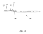
- FIG. 16 is a perspective view of the flanking plate of actuation mechanism of the laparoscopic scissors of FIG. 12 ;
- FIG. 17 is a perspective view of a pair of flanking plates of actuation mechanism of the laparoscopic scissors of FIG. 12 .
- a laparoscopic scissors having an elongate shaft 10 with a proximal end 12 connected to a manipulator, such as a handle assembly 20 .
- a scissor assembly 30 Extending from a distal end 14 of the elongate shaft 10 is a scissor assembly 30 , which, in some embodiments includes a pair of scissor blades pivotally movable with respect to one another.
- the elongate shaft 10 can be sized to fit through an access port, such as a trocar cannula, that extends into an insufflated abdominal cavity for use in a laparoscopic surgical procedure.
- the elongate shaft 10 can be sized for use in other surgical environments.
- the elongate shaft 10 comprises an elongate generally cylindrical outer tube, although in other embodiments, the elongate shaft 10 can have other geometries such as square tubes or tubes having eccentric or oval cross-sectional profiles.
- An actuation mechanism 40 ( FIGS. 5A , 5 B, 8 A, 8 B) can extend through at least a portion of the elongate shaft 10 and can operatively couple the handle assembly 20 ( FIGS. 8A , 8 B) to the scissor assembly 30 ( FIGS. 5A , 5 B).
- a proximal end of the actuation mechanism 40 is coupled to the handle assembly 20 ( FIGS. 8A , 8 B), and a distal end of the actuation mechanism 40 is coupled to the scissor assembly 30 ( FIGS. 5A , 5 B).
- the elongate shaft 10 in some embodiments is formed of a metallic material and portions of the actuation mechanism extending through the tube in some embodiments are formed of a plastic material. It is contemplated that in other embodiments, other materials may be used. Where the elongate shaft 10 is made of a metallic material, the elongate shaft 10 can be covered with an electrically insulating material or sheath, such as a plastic material, which in one aspect may be a shrink tubing material.
- the handle assembly 20 can comprise a stationary handle 22 and a movable handle 24 .
- the actuation mechanism 40 can be longitudinally slid within the elongate shaft 10 to move the scissor assembly 30 between an open and closed configuration ( FIGS. 5 , 8 ).
- laparoscopic scissors is illustrated as having a handle assembly with a stationary handle and a movable handle, in other embodiments, it is contemplated that other handle assemblies can be used with the laparoscopic scissors described herein, such as, for example, a handle assembly having a slidable plunger, or a handle assembly having two movable handles.
- the laparoscopic scissor instrument can be configured to perform electrocautery.
- the handle assembly 20 further includes an electrical connecting post 50 ( FIGS. 1 and 11 ) to provide for cauterization of tissue during a procedure.
- the electrical connecting post 50 can be attached to the handle assembly 20 so as to extend at transversely to or generally perpendicular to an outer surface of the handle assembly 20 and can include an electrical conductor such as a spring or wire extending into the handle assembly 20 .
- the electrical conductor can extend from the connecting post 50 into contact with the elongate shaft 10 to provide electrical contact to the scissor assembly 30 .
- the scissor assembly 30 comprises a first scissor blade 32 and a second scissor blade 34 .
- the scissor assembly 30 can be actuated between an open state and a closed state to cut items such as body tissue positioned between the scissor blades 32 , 34 .
- the first scissor blade 32 is spaced from the second scissor blade 34 when the scissor assembly is in a normal or open state.
- the first scissor blade 32 is proximate the second scissor blade 34 when the scissor assembly 30 is in an actuated or closed state.
- the first scissor blade 32 may be considered, although not limited to, an outside or outer blade in relation to the opposing, second scissor blade 34 that may be considered, although not limited to, an inside or inner blade.
- each of the first and second scissor blades 32 , 34 has a profile 36 following a curve defined by a polynomial, such as a parabola. Desirably, the relationship between the curves of the first and second blades creates continuous bias force between the blades as the scissor assembly 30 is opened and closed.
- scissor blade 32 , 34 for use in embodiments of laparoscopic scissor instrument is illustrated.
- a single scissor blade 32 , 34 is illustrated as it is contemplated that substantially identical scissor blades or manufacturing blanks for scissor blades 32 , 34 can be interchangeable in some embodiments of laparoscopic scissor instrument, thus reducing manufacturing and inventory costs.
- the first and scissor blades can include certain variations with respect to one another. For example, in some embodiments the profile 36 discussed above can be different between the first and second blade.
- the scissor blade 32 , 34 has an interface surface 60 , an opposing surface 62 opposite the interface surface 60 , a distal, cutting portion 64 , and a proximal, actuation portion 66 .
- the scissor blade 32 , 34 can further include a pivot 68 and an actuation protrusion 70 on the actuation portion 66 thereof.
- the pivot 68 extends from the opposing surface 62 of the actuation portion 66
- the actuation protrusion 70 extends from the interface surface 60 of the actuation portion 66 .
- FIG. 3A illustrates an embodiment of scissor blade 32 , 34 having a pivot 68 comprising a pivot protrusion.
- the pivot protrusion can be formed on the scissor blade 32 , 34 .
- the protrusion can be adhered to the scissor blade.
- the pivot protrusions extending from the opposing surfaces 62 of the scissor blades 32 , 34 leave a clearance between the scissor blades 32 , 34 to allow a relatively long operational stroke of the actuation mechanism as there is no pivot pin extending through (and between) both scissor blades 32 , 34 in an assembled scissor assembly.
- a relatively long operational stroke can allow the actuation mechanism to be configured to deliver a relatively large amount of leverage to the scissor blades 32 , 34 , allowing multiple tissue types to be cut.
- the relatively long operational stroke can allow the actuation mechanism and handle assembly to be configured to allow for a relatively long movement of the movable handle, thus providing enhanced fine control of the position of the scissor assembly.
- the scissor blades 32 , 34 can be desirable to manufacture with a process that involves relatively few low cost manufacturing steps in order to minimize cost. Accordingly, it can be desirable to form the edges, holes, and pins of the scissor blades 32 , 34 with a stamping process.
- the pin or pivot protrusion can be formed using a semi-perforation process.
- a grinding or honing operation can then form a cutting edge 72 on the scissor blade 32 , 34 .
- the bias curve which is parabolic in some embodiments, can be formed on the scissor blades 32 , 34 by means of a press.
- the pivot protrusion and/or the actuation protrusion can be adhered or welded to the scissor blade 32 , 34 after the initial forming of the scissor blade 32 , 34 .
- the scissor blade 32 ′, 34 ′ for use in a laparoscopic surgical instrument is illustrated.
- the scissor blade 32 ′, 34 ′ comprises an interface surface 60 ′, an opposing surface 62 ′, a cutting portion 64 ′, an actuation portion 66 ′, and an actuation protrusion 70 ′ substantially as described above with respect to the scissor blade 32 , 34 of FIG. 3A .
- the scissor blade 32 ′, 34 ′ of FIG. 3B includes a pivot 68 ′ comprising a pivot aperture adapted to receive a pivot pin 74 ′ or rivet therein.
- the pivot pin 74 ′ ( FIG. 4B ) can extend between the pivots 60 ′ of each scissor blade 32 ′, 34 ′ and pivotably couple the scissor blades 32 ′, 34 ′ to one another and to the elongate shaft 10 .
- This pivot pin 74 ′ arrangement can shorten the operational stroke of the actuation mechanism relative to the scissor blade 32 , 34 of FIG. 3A .
- each of the first and second scissor blades 32 , 34 , 32 ′, 34 ′ has a cutting edge 72 , 72 ′ that is ground at an angle ( FIGS. 4A , 4 B).
- the cutting edges 72 , 72 ′ extend from the actuation portion 66 , 66 ′ of each of the first and second scissor blades 32 , 34 , 32 ′, 34 ′ along an edge of the cutting portion 64 , 64 ′ of each of the first and second scissor blades 32 , 34 , 32 ′, 34 ′.
- the actuation mechanism 40 translates through the elongate shaft 10 during a closing stroke, the point of contact or cut point progressively travels along the cutting edges 72 from a proximal portion to a distal portion of the cutting edges 72 .
- the actuation portion 66 , 66 ′ of each of the first and second scissor blades 32 , 34 , 32 ′, 34 ′ can have an actuation protrusion 70 , 70 ′ that can connect the respective blade to the actuation mechanism 40 .
- the actuation protrusion 70 , 70 ′ comprises a projection, such as a post or pin. The projection can extend from the actuation portion 66 , 66 ′ of each of the first and second blades 32 , 34 , 32 ′, 34 ′ to couple the blades to camming slots in the actuation mechanism 40 .
- the actuation mechanism 40 can comprise an actuation rod 42 having a proximal end and a distal end and a scissor actuator 44 at the distal end of the actuation rod 42 .
- the scissor actuator 44 is a fork design. With the fork design, an actuation slot 46 can be formed on each fork member of the scissor actuator 44 .
- the actuation portion 66 of the blades can be operatively coupled to the actuation mechanism 40 .
- the actuation protrusion 70 of the first scissor blade 32 can be positioned in the an actuation slot 46 on one fork member of the scissor actuator 44 and the actuation protrusion 70 of the second scissor blade 34 can be positioned in the actuation slot 46 on the other fork member of the scissor actuator 44 .
- the actuation slot 46 can extend transverse to, or in a curved arrangement relative to a longitudinal axis of the scissor actuator 44 .
- the geometry of the actuation slot 46 can define an actuation profile for the scissor assembly.
- a relatively steep slope of the actuation slot 46 relative to the longitudinal axis of the scissor actuator 44 can indicate an actuation profile with a relatively short stroke of the actuator and corresponding rapid opening and closing of the scissor blades 32 , 34 .
- a relatively shallow slope of the actuation slot 46 relative to the longitudinal axis of the scissor actuator 44 can indicate a relatively long actuation stroke and relatively high leverage and slow opening and closing of the scissor blades.
- a curved actuation slot 46 can desirably have a relatively shallow slope over portions of blade travel and a relatively steep stroke over other portions of blade travel.
- the blades could be initially rapidly advanced towards one another for rapid initial closing of a closing actuation, then slowly advanced towards one another for a subsequent portion of a closing actuation.
- the scissor blades could be quickly advanced towards tissue therebetween, then more slowly advanced once the blades have contacted the tissue therebetween to provide relatively high leverage and fine control while cutting the tissue.
- the scissor blades 32 , 34 can be pivotally coupled to the elongate shaft 10 by pivot 68 such as a pin or post on the scissor blades 32 , 34 .
- the pivot 68 on each blade can engage with a corresponding aperture 16 formed in the distal end 14 of the elongate shaft 10 .
- the engagement of the pivots 68 of each blade 32 , 34 with the elongate shaft 10 allows the blades 32 , 34 to pivot about the pivot 68 when the scissor assembly 30 is actuated between the open and closed configurations.
- the actuation mechanism 40 is moved in one direction, the actuation protrusions 70 of each of the blades 32 , 34 will cam against their respective actuation slots 46 on the actuation mechanism 40 .
- the actuation mechanism 40 may be a single integral component, or, in other embodiments may have multiple pieces assembled together.
- the scissor actuator 44 includes a fork design including fork members each comprising a separate flanking plate 48 .
- the flanking plates 48 can each be coupled with a distal end of the actuation rod 42 .
- a proximal portion of each of the flanking plates can be adapted to mate and couple with a distal portion of the actuation rod 42
- a distal portion of each of the flanking plates 48 can be adapted to mate with and actuate one of the scissor blades 32 , 34 .
- each of the flanking plates 48 is coupled to the actuation rod 42 by heat staking. In other embodiments, each of the flanking plates can be coupled to the actuation rod 42 by press-fit, fastener, adhesive, or another mechanical or chemical process.
- the flanking plates 48 can include one or more apertures, slots, recesses, grooves, or other feature to facilitate coupling of the flanking plates to the actuation rod 42 .
- the scissor actuator 44 of the actuation mechanism 40 can be configured to apply a biasing force to the scissor assembly 30 .
- a biasing force on the scissor assembly 30 can maintain a cutting contact between cutting edges 72 of the first and second scissor blades 32 , 34 throughout the range of motion of the scissor assembly 30 from the open position to the closed position.
- the fork design of the scissor actuator 44 can be configured such that the flanking plates 48 apply a biasing force to the scissor assembly 30 .
- each flanking plate 48 includes a bend 49 or knuckle.
- an actuation mechanism 40 ′ for coupling to a laparoscopic scissor instrument having pinned pivoting blades, such as those illustrated in FIG. 3B is illustrated.
- the actuation mechanism 40 ′ includes an actuation rod 42 ′ coupled to a scissor actuator 44 ′, substantially as discussed above with respect to the embodiment of FIGS. 4A , 5 A, and 6 .
- the scissor actuator 44 ′ includes an actuation slot 46 ′ formed at a distal end thereof.
- the scissor actuator 44 ′ comprises a forked design having two flanking plates 48 ′ each having an actuation slot 46 ′ formed therein.
- each flanking plate 48 ′ also includes a pivot slot 47 ′ adapted to receive the pivot pin 74 ′.
- the actuation slot 46 ′ of the scissor actuator 44 ′ of FIGS. 4B and 5B is relatively short compared to the actuation slot 46 of the scissor actuator 44 of FIGS. 4A , 5 A, and 6 .
- a scissor instrument having pinned-pivot scissor blades (such as those illustrated in FIGS. 4B and 5B ) tends to have a shorter actuation stroke than a scissor instrument having pin-less scissor blades (such as those illustrated in FIGS. 4A , 5 A, and 6 ).
- flanking plates 48 ′ coupled to the actuation rod 42 ′
- the distal portions of the flanking plates 48 ′ are spaced from each other such that the actuation portions 66 ′ of each of the first and second scissor blades 32 ′, 34 ′ may be positioned between distal portions of the flanking plates 48 ′.
- This spaced arrangement of the flanking plates 48 ′ differs from the bias-generating bends 49 of the flanking plates 48 of the scissor actuator 44 of FIGS. 4A , 5 A, and 6 .
- each of the flanking plates 48 ′ has a generally-longitudinally extending pivot slot 47 ′ that provides clearance for the pivot pin 74 ′ as the actuation mechanism 40 ′ is moved distally and proximally within the elongate shaft 10 .
- the pivot slots 47 ′ can be sufficiently long to provide for a full stroke length of the scissor assembly 30 ′.
- each of the flanking plates 48 ′ also has a slanted or curved actuation slot 46 ′ into which the actuation protrusion of the respective scissor blade 32 ′, 34 ′ can be positioned.
- the actuation slots 46 ′ extend transversely to each other to facilitate opening and closing of the scissor blades 32 ′, 34 ′ as the actuation mechanism 40 ′ translates distally and proximally within the elongate shaft 10 .
- flanking plates 48 ′ may be coupled to the actuation rod 42 ′ by methods such as heat staking, fasteners, and adhesive.
- the flanking plates 48 ′ and the actuation rod 42 ′ may have mating features, such as a raised projection for mating into an aperture, to facilitate proper positioning of the flanking plates 48 ′ in relation to the actuation rod 42 ′.
- flanking plates 48 ′ and actuation rod 42 ′ may have features, such as angled surfaces at the proximal end of the flanking plates that conform to a surface on the actuation rod 42 ′, for ensuring that each flanking plate 48 ′ is positioned on the proper side of the actuation rod 42 ′ and oriented in the proper position.
- a scissor assembly 30 , 30 ′ having pins on scissor blades 32 , 34 , 32 ′, 34 ′ to mate with a slotted actuation mechanism 40 , 40 ′ can have a reduced operational height as compared with a scissor assembly having slots formed on scissor blades driven by an actuated pin.
- the scissor assemblies 30 , 30 ′ described herein can be configured such that their operational height is smaller than a diameter of the elongate shaft 10 .
- the scissor assemblies described herein advantageously have a reduced “wingspan,” and thus a reduced risk of interfering with tissue or distorting an elastomeric sheath around the elongate shaft.
- the blades 32 , 34 , 32 ′, 34 ′ can be formed from conventional stamping and then heat treated.
- the blades 32 , 34 , 32 ′, 34 ′ can be formed from a blank of pre-hardened material and then EDM cut, waterjet cut, laser cut or even machined to obtain the final shape.
- protrusions, projections or pins of the actuation portions of the blades 32 , 34 , 32 ′, 34 ′ can be formed directly onto the blades, or they can be added to the blades 32 , 34 , 32 ′, 34 ′ as a separate component.
- Protrusions or pins that are made as separate components from the blades can be attached to the blades in any one or a combination of ways.
- the protrusions can be press-fitted, swaged, threaded and/or welded to the blades 32 , 34 , 32 ′, 34 ′.
- a sheet of material can be stamped or machined to include a pivot 68 ′ hole as well as the actuation protrusion 70 ′ pin or a pivot 68 protrusion and actuation protrusion 70 .
- the sheet can then be heat treated and sent to a form grinder, which can grind one profile of the blade 32 , 34 , 32 ′, 34 ′.
- the ground plate can then be sent to be EDM cut and the second profile can be cut out.
- This type of process can yield numerous components, with the actuation protrusion pin 70 , 70 ′ and pivot 68 protrusion integrally located, for relatively low cost.
- MIM metal injection molding
- PM powder metallurgy
- the proximal, actuation portion 66 , 66 ′ of each blade 32 , 34 , 32 ′, 34 ′ has a relatively reduced area. In this manner, very little or no part of the blades 32 , 34 , 32 ′, 34 ′ of the scissor assembly 30 , 30 ′ extend beyond the diameter of the elongate shaft 10 during actuation of the scissor assembly 30 , 30 ′.
- the actuation rod 42 , 42 ′ may be made in two or more rod portions 52 , 54 . If made in separate rod portions 52 , 54 , the rod portions 52 , 54 should be coupled by a connection 56 that can withstand two or more times the maximum service tension of the actuation mechanism 40 , 40 ′. For example, if the maximum service tension is twenty-eight pounds, then the connection 56 should desirably be able to withstand tension of fifty-six pounds.
- connection 56 having a sequential barbed configuration is illustrated.
- the connection 56 has a shape similar to a fir tree, on a first actuation rod portion 52 that mates to a mating female portion on a second actuation rod portion 54 .
- the barbs of the “fir tree” may be sequentially smaller from the base to the tip.
- the female portion may tend to open or separate when tension is applied to the actuation rod 42 , 42 ′.
- the mating ends may each include a male portion and a female portion so that the end of the male mating portion of each piece of the actuation rod is covered by the female mating portion of the adjoining piece of the actuation rod.
- connection 56 is illustrated as a sequential barbed connection, it is contemplated that in other embodiments, other connection types can be used to connect portions of actuation rods in laparoscopic scissor instruments described herein.
- a proximal portion of the elongate shaft 10 may have a retention member 18 , 18 ′ projecting radially therefrom that fits into a retention cavity 26 , 26 ′ in the handle assembly 20 , 20 ′.
- FIG. 8A illustrates one embodiment of retention member 18 comprising a retention clip.
- the retention clip can be secured to the elongate shaft 10 in slots formed in an outer surface of the shaft.
- the retention clip can maintain a longitudinal position of the elongate shaft relative to the handle assembly 20 by interfacing with a retention cavity 26 that can be formed of a first retention rib positioned proximally to the retention clip and a second retention rib positioned distally to the retention clip.
- This interface between retention member 18 and retention cavity 26 allows the elongate shaft 10 to be rotated relative to the handle assembly about a longitudinal axis of the elongate shaft 10 , but restricts the elongate shaft 10 from being moved axially with respect to the handle assembly about the longitudinal axis.
- FIG. 8B illustrates another embodiment of retention member 18 ′ for use in some embodiments of laparoscopic scissor instrument.
- the retention member 18 ′ comprises a retention collar that can be attached onto the elongate shaft 10 by one or a combination of coupling techniques, such as fasteners, adhesives, and mating protrusions and apertures.
- the collar is made from two or more identical pieces coupled together around the tube of the shaft.
- the retention collar 18 ′ can engage with a retention cavity 26 ′ formed in the handle assembly 20 ′ such that the elongate shaft 10 is rotatable with respect to the handle assembly 20 ′, but axial movement of the elongate shaft 10 with respect to the handle assembly 20 ′ is restricted.
- FIG. 9A illustrates a first embodiment in which a first actuation disc 80 and a second actuation disc 82 are formed on the proximal end of the actuation rod 42 , forming a space 84 therebetween.
- the actuation discs 80 , 82 can be integrally formed with the actuation mechanism 40 or can be joined thereto by mechanical or chemical fastening or adhesive.
- the actuation discs 80 , 82 can have different sizes such that for example, the first actuation disc 80 has a larger diameter and thickness than the second actuation disc 82 .
- the actuation discs 80 , 82 can be substantially the same size and shape, or can have other variations in size and shape than the illustrated embodiment.
- the second actuation disc 82 can be thicker and have a larger diameter than the first actuation disc 80 ).
- a retention feature 86 is formed on the movable handle 24 and engages with at least one of the discs 80 , 82 , and the space 84 such that movement of the movable handle axially slides the actuation rod 42 within the elongate tube 10 .
- the retention feature 86 can include gripping flanges 88 adapted to engage at least one of the discs 80 , 82 , and the space 84 and sidewalls 92 adapted to maintain the coupling between the actuation rod 42 and the movable handle 24 .
- the retention feature 86 can be a slip fit retention feature to facilitate assembly of the movable handle with the actuation rod 42 .
- the retention feature 86 can be sized and configured to perform repeated scissor actuation cycles cutting various tissue types without fracturing, failing, or slipping off of the actuation discs 80 , 82 .
- the retention feature 86 can have a rounded profile to reduce stress concentrations at curved portions thereof.
- the disc shapes are relatively simple to manufacture.
- the actuation disc assembly illustrated in FIG. 8A is relatively low profile and allows rotation of the actuation mechanism 40 with respect to the handle assembly 20 about the longitudinal axis of the elongate shaft 10 .
- FIG. 9B illustrates another embodiment of coupling between the actuation mechanism 40 ′ and the movable handle 24 .
- the coupling includes an enlarged proximal end such as an actuation ball 80 ′ adapted to mate to a retention clamp on the movable handle.
- the actuation ball 80 ′ can be integrally formed with the actuation rod 42 ′, or can be joined thereto by other mechanical or chemical coupling such as a fastener or adhesive coupling.
- the actuation ball 80 ′ can fit into a mating groove or cavity formed in the retention clamp to provide a rotatable ball-and-socket joint.
- a distal end of various embodiments of laparoscopic scissors is illustrated with a sheath 15 , such as an electrically insulating shrink tube disposed about the elongate shaft 10 .
- the scissor assembly 30 can be configured such that an operational height of the scissor assembly is smaller than a diameter of the elongate shaft 10 such that the scissor blades 32 , 34 remain inside diameter of the elongate shaft, and the sheath 15 is not distorted or distended during operation of the scissors.
- the laparoscopic scissors can include a rotatable elongate shaft such that a user can rotate the scissor assembly 30 as desired during use.
- the elongate shaft can have infinite 360 degree rotation relative to the handle assembly. In other embodiments, it can be desirable to have rotation stops to limit the rotation of the elongate shaft to a predetermined range.
- the laparoscopic scissors can include a rotational knob 90 coupled to the elongate shaft 10 allowing the elongate shaft 10 and scissor assembly 30 to rotate relative to the handle assembly 20 about the longitudinal axis of the elongate shaft 10 .
- the couplings between the handle assembly and the elongate shaft 10 can be configured to allow rotation therebetween about the longitudinal axis of the elongate shaft 10 .
- FIGS. 12-17 various aspects of another embodiment of laparoscopic scissors are illustrated.
- a scissor assembly and actuation mechanism that includes both a relatively high degree of compliance such that the actuation mechanism imparts a spring force on the scissor blades to generate a desired amount of blade tension and a high degree of stiffness such that the laparoscopic scissors can be used to cut tissue with a relatively high resiliency.
- the illustrated embodiment includes scissor blades that are pinned or riveted to one another to provide a scissor assembly 130 with a relatively high stiffness.
- the illustrated embodiment also includes an actuation mechanism 140 positioned between the scissor blades 132 , 134 to provide a desirable amount of tension on the blades during a cutting operation even when cutting relatively resilient tissue.
- an actuation mechanism 140 positioned between the scissor blades 132 , 134 to provide a desirable amount of tension on the blades during a cutting operation even when cutting relatively resilient tissue.
- Various aspects of the scissor blades 132 , 134 and actuation mechanism 140 of this illustrated embodiment advantageously further enhance the blade tension and stability of the scissors during a cutting operation.
- the scissor blades 132 , 134 each comprise an interface surface 160 , an opposing surface 162 , a cutting portion 164 , an actuation portion 166 , an actuation protrusion 170 , and a cutting edge 172 , substantially as described above with respect to the scissor blades 32 , 34 , 32 ′, 34 ′ of FIGS. 3A-3B .
- the scissor blades 132 , 134 each include a pivot 168 comprising a pivot aperture adapted to receive a pivot pin 174 or rivet therein similar to the pivot 68 ′ of the scissor blades 32 ′, 34 ′ of FIG. 3B .
- FIG. 13 a perspective view of a scissor assembly 130 of embodiment of laparoscopic scissors is illustrated.
- the scissor blades 132 , 134 are coupled to an elongate shaft 110 by a pivot pin 174 or rivet passing through the elongate shaft 110 and pivots 168 of each of the scissor blades 132 , 134 .
- the elongate shaft 110 can include an aperture 180 having a crimped edge 182 .
- the crimped edge 182 can extend into an interior of the elongate shaft 110 to interface with flanking plates 148 of an actuation mechanism 140 of the scissors.
- the crimped edge 182 can provide a longitudinal guide surface for one of the flanking plates 148 to maintain an operational stroke defined by longitudinal sliding of the actuation mechanism relative to the elongate shaft.
- the elongate shaft 110 can include a pair of apertures 180 each including a crimped edge 182 that are diametrically opposed to one another.
- one of the crimped edges 182 provides a longitudinal guide surface for one of the flanking plates 148
- the diametrically opposed crimped edge provides a longitudinal guide surface for the other of the flanking plates 148 .
- the longitudinal guide surfaces provided by one or more crimped edges 182 can enhance the stability of the actuation mechanism 140 , reducing any potential misalignment of the actuation mechanism 140 , in particular when the scissor assembly 130 is closing on resilient tissue.
- a crimped edge 182 in other embodiments, another type of projection such as a notch, post, rail, guide, or tab can extend into an interior of the elongate shaft to interface with the actuation mechanism.
- the elongate shaft does not include an aperture, rather, a projection such as a crimp, notch, post, rail, guide, or tab can be formed in, fixed to, or adhered to an interior surface of the elongate shaft.
- FIG. 14 a perspective view of the scissor assembly 130 and actuation mechanism 140 of a pair of laparoscopic scissors are illustrated.
- the elongate shaft 110 is presented as a translucent surface such that the actuation mechanism 140 is visible.
- the actuation mechanism can comprise an actuation rod 142 coupled to a pair of flanking plates 148 forming a forked scissor actuator 144 similar to the forked scissor actuator described above with respect to FIGS. 5A and 6 .
- Each of the flanking plates 148 includes an actuation slot 146 which receives an actuation protrusion 170 from a corresponding one of the scissor blades 132 , 134 such that longitudinal sliding movement of the actuation mechanism 140 relative to the elongate shaft 110 actuates the scissor blades to pivot relative to one another about the pivot pin 174 or rivet and open or close.
- FIG. 15 a detail perspective view of the scissor assembly 130 and actuation mechanism 140 of the pair of laparoscopic scissors is illustrated.
- the elongate shaft 110 is presented as a translucent surface such that the actuation mechanism 140 is visible.
- the actuation mechanism 140 is positioned between one scissor blade 132 and the other scissor blade 134 such that a spring force can be generated by the actuation mechanism 140 to provide a cutting tension between the scissor blades 132 , 134 . Similar to the actuation mechanism 40 described above and illustrated in FIG.
- each of the flanking plates 148 comprises a bend 149 or knuckle that bear on one another such that an outward biasing force is applied to the scissor blades 132 , 134 .
- This outward biasing force tends to bias the cutting portions of the scissor blades 132 , 134 towards one another, thus enhancing the ability of the scissor assembly to cut tissue types with relatively high resiliency.
- each flanking plate 148 includes one or more projections 184 , 186 extending from one of the flanking plates 148 and contacting the other flanking plate 148 when a pair of flanking plates 148 is assembled to form the forked scissor actuator 144 .
- each flanking plate 148 includes two projections 184 , 186 that are positioned in an opposed arrangement such that when a pair of flanking plates 148 is assembled to form the forked scissor actuator 144 , the projections 184 , 186 on opposing flanking plates 148 do not contact one another. Rather, the projections 184 , 186 each contact a surface of the opposing flanking plate 148 such that in the illustrated embodiment with each flanking plate 148 having two projections 184 , 186 , four points of contact between the pair of flanking plates 148 are established.
- the contact provided by several relatively small projections 184 , 186 maintains a desired spacing of the flanking plates 148 relative to one another while allowing compliance in the actuation mechanism 140 to generate a desired outward biasing force.
- the projections 184 , 186 are located on the flanking plates 148 so as not to interfere with the position of the slot 146 or the pivot pin 174 or rivet during operation of the actuation mechanism 140 .
- two projections 184 , 186 are positioned on each flanking plate 148 .
- more or fewer than two projections such as, for example, one, three, four, five, or more than five projections can be positioned on each flanking plate 148 .
- one flanking plate has a different number of projections from the other flanking plate making up an actuator mechanism.
- one flanking plate may have a single projection and the other flanking plate in the actuator mechanism may have two or more projections.
- the flanking plates 148 can comprise a metallic material with projections 184 , 186 that are formed by a stamping operation during manufacture of the flanking plates 148 such that a dimple is formed on a surface of the flanking plate 148 opposite the projections 184 , 186 .
- the projections 184 , 186 can comprise shims that are welded, fixed, or adhered to a surface of each flanking plate 148 .
- the flanking plates can comprise a non-metallic material having integrally formed projections, such as can be formed in a molding operation.
- each flanking plate 148 includes an actuation slot 146 for receiving the actuation protrusion 170 of the scissor blades 132 , 134 .
- this actuation slot 146 tends to be shorter than actuation slot 46 of a scissor instrument having pin-less scissor blades (such as illustrated in FIGS. 4A , 5 A, and 6 ).
- actuation slot 146 can have a first end and a second end opposite the first end that provide stops to define the open and closed limits of the actuation stroke of the scissors.
- each flanking plate 148 can include a notch 188 formed at the distal end thereof.
- the notch 188 can be sized and configured to receive the pivot pin 174 or rivet of the scissor assembly 130 during actuation of actuation mechanism 140 such that movement of the flanking plate 1483 full actuation stroke does not interfere with the pivot pin 174 .
- this notched configuration allows the actuation mechanism 140 to remain proximal of pivot pin 174 to provide outward biasing force to the scissor assembly 130 proximal of pivot pin 174 during an actuation stroke of the actuation mechanism 140 .
- flanking plate 148 ( FIG. 16 ) and a pair of flanking plates 148 ( FIG. 17 ) of an actuation mechanism 140 for laparoscopic scissors are illustrated.
- the flanking plates 148 each comprise a bend 149 or knuckle, a pair of projections 184 , 186 , an actuation slot 146 , and a notch 188 .
- the flanking plates 148 can provide an actuation mechanism for laparoscopic scissors having a desired stability and compliance for use on resilient tissue.
Abstract
Description
Claims (11)
Priority Applications (1)
| Application Number | Priority Date | Filing Date | Title |
|---|---|---|---|
| US13/249,629 US8523893B2 (en) | 2010-09-30 | 2011-09-30 | Laparoscopic scissors |
Applications Claiming Priority (2)
| Application Number | Priority Date | Filing Date | Title |
|---|---|---|---|
| US38835410P | 2010-09-30 | 2010-09-30 | |
| US13/249,629 US8523893B2 (en) | 2010-09-30 | 2011-09-30 | Laparoscopic scissors |
Publications (2)
| Publication Number | Publication Date |
|---|---|
| US20120083814A1 US20120083814A1 (en) | 2012-04-05 |
| US8523893B2 true US8523893B2 (en) | 2013-09-03 |
Family
ID=45890440
Family Applications (1)
| Application Number | Title | Priority Date | Filing Date |
|---|---|---|---|
| US13/249,629 Active 2031-10-20 US8523893B2 (en) | 2010-09-30 | 2011-09-30 | Laparoscopic scissors |
Country Status (1)
| Country | Link |
|---|---|
| US (1) | US8523893B2 (en) |
Cited By (3)
| Publication number | Priority date | Publication date | Assignee | Title |
|---|---|---|---|---|
| US20120303049A1 (en) * | 2010-10-29 | 2012-11-29 | Acp Japan Co., Ltd. | Surgical instrument |
| US20190254236A1 (en) * | 2016-11-07 | 2019-08-22 | Claudio Bortolussi | Disbudding secateurs |
| WO2020205374A1 (en) * | 2019-03-29 | 2020-10-08 | Gyrus Acmi, Inc. D/B/A Olympus Surgical Technologies America | Forceps with two-part drive bar |
Families Citing this family (5)
| Publication number | Priority date | Publication date | Assignee | Title |
|---|---|---|---|---|
| CA2956459C (en) * | 2014-07-28 | 2017-11-21 | Teleflex Medical Incorporated | Needlescopic scissor end effector |
| USD785172S1 (en) * | 2015-02-09 | 2017-04-25 | Getac Technology Corporation | Handle for endoscopic surgical clip applier |
| ITUB20159277A1 (en) * | 2015-12-17 | 2017-06-17 | Giuseppe Lauria | SURGICAL DEVICE and AUXILIARY DEVICES FOR CIRCUMCISION INTERVENTIONS |
| ITUB20159402A1 (en) * | 2015-12-17 | 2017-06-17 | Giuseppe Lauria | SURGICAL DEVICE and AUXILIARY DEVICES FOR CIRCUMCISION INTERVENTIONS |
| AU2019380263A1 (en) * | 2018-11-15 | 2021-05-20 | Applied Medical Resources Corporation | Laparoscopic grasper with force-limiting grasping mechanism |
Citations (49)
| Publication number | Priority date | Publication date | Assignee | Title |
|---|---|---|---|---|
| US2790437A (en) | 1955-10-12 | 1957-04-30 | Welch Allyn Inc | Surgical instrument |
| US4569131A (en) | 1983-06-01 | 1986-02-11 | Richard Wolf Gmbh | Tool having a handle with an interchangeable insert portion |
| US5147373A (en) | 1991-04-29 | 1992-09-15 | Ferzli George S | Laparoscopic instrument |
| US5147357A (en) | 1991-03-18 | 1992-09-15 | Rose Anthony T | Medical instrument |
| US5174300A (en) | 1991-04-04 | 1992-12-29 | Symbiosis Corporation | Endoscopic surgical instruments having rotatable end effectors |
| US5192298A (en) | 1990-05-10 | 1993-03-09 | Symbiosis Corporation | Disposable laparoscopic surgical instruments |
| US5290308A (en) | 1992-07-15 | 1994-03-01 | Edward Weck Incorporated | Endoscopic instrument |
| US5293878A (en) | 1991-04-04 | 1994-03-15 | Symbiosis Corporation | Endoscopic surgical instruments having stepped rotatable end effectors |
| US5304203A (en) | 1992-10-20 | 1994-04-19 | Numed Technologies, Inc. | Tissue extracting forceps for laparoscopic surgery |
| US5308358A (en) | 1992-08-25 | 1994-05-03 | Bond Albert L | Rigid-shaft surgical instruments that can be disassembled for improved cleaning |
| US5312434A (en) | 1992-12-21 | 1994-05-17 | Lawrence Crainich | Medical instrument |
| US5331971A (en) | 1990-05-10 | 1994-07-26 | Symbiosis Corporation | Endoscopic surgical instruments |
| US5342390A (en) | 1990-05-10 | 1994-08-30 | Symbiosis Corporation | Thumb-activated actuating member for imparting reciprocal motion to a push rod of a disposable laparoscopic surgical instrument |
| US5342381A (en) | 1993-02-11 | 1994-08-30 | Everest Medical Corporation | Combination bipolar scissors and forceps instrument |
| US5352222A (en) | 1994-03-15 | 1994-10-04 | Everest Medical Corporation | Surgical scissors with bipolar coagulation feature |
| US5358508A (en) | 1993-09-15 | 1994-10-25 | Eric Cobb | Laparoscopic device |
| US5368606A (en) | 1992-07-02 | 1994-11-29 | Marlow Surgical Technologies, Inc. | Endoscopic instrument system |
| US5383888A (en) | 1992-02-12 | 1995-01-24 | United States Surgical Corporation | Articulating endoscopic surgical apparatus |
| US5392789A (en) | 1991-04-04 | 1995-02-28 | Symbiosis Corporation | Endoscopic scissors having scissor elements loosely engaged with a clevis |
| US5478347A (en) | 1990-10-05 | 1995-12-26 | United States Surgical Corporation | Endoscopic surgical instrument having curved blades |
| US5486189A (en) | 1990-10-05 | 1996-01-23 | United States Surgical Corporation | Endoscopic surgical instrument |
| US5496347A (en) | 1993-03-30 | 1996-03-05 | Olympus Optical Co., Ltd. | Surgical instrument |
| US5499992A (en) | 1992-06-24 | 1996-03-19 | Microsurge, Inc. | Reuseable endoscopic surgical instrument |
| US5522830A (en) | 1990-10-05 | 1996-06-04 | United States Surgical Corporation | Endoscopic surgical instrument |
| US5569243A (en) | 1993-07-13 | 1996-10-29 | Symbiosis Corporation | Double acting endoscopic scissors with bipolar cautery capability |
| US5578052A (en) | 1992-10-27 | 1996-11-26 | Koros; Tibor | Insulated laparoscopic grasper with removable shaft |
| US5746759A (en) | 1992-06-24 | 1998-05-05 | Microsurge, Inc. | Reusable endoscopic surgical instrument |
| US5769841A (en) | 1995-06-13 | 1998-06-23 | Electroscope, Inc. | Electrosurgical apparatus for laparoscopic and like procedures |
| US5782834A (en) | 1993-01-29 | 1998-07-21 | Smith & Nephew, Inc. | Surgical instrument |
| US5782859A (en) | 1992-02-12 | 1998-07-21 | United States Surgical Corporation | Articulating endoscopic surgical apparatus |
| US5782748A (en) | 1996-07-10 | 1998-07-21 | Symbiosis Corporation | Endoscopic surgical instruments having detachable proximal and distal portions |
| US5810879A (en) | 1997-02-27 | 1998-09-22 | Microline, Inc. | Laparoscopic instrument |
| US5827323A (en) | 1993-07-21 | 1998-10-27 | Charles H. Klieman | Surgical instrument for endoscopic and general surgery |
| US5849022A (en) | 1994-07-29 | 1998-12-15 | Olympus Optical Co., Ltd. | Medical instrument for use in combination with endoscopes |
| US5868785A (en) | 1991-12-13 | 1999-02-09 | Unisurge Holdings, Inc. | Hand-held surgical device and tools for use therewith, assembly and method |
| US5924720A (en) | 1997-04-03 | 1999-07-20 | Keehne; Robert W. | Wheelchair with elevatable seat |
| US5947996A (en) | 1997-06-23 | 1999-09-07 | Medicor Corporation | Yoke for surgical instrument |
| US6015426A (en) | 1994-07-13 | 2000-01-18 | Tnco, Inc. | Rotatable linkage for micro-instrument |
| US6086606A (en) | 1998-05-06 | 2000-07-11 | Knodel; Bryan D. | Manually-operable surgical tool suitable for laparoscopic operations, readily adaptable for different functions by quick change of tissue-contacting operational elements |
| US6168605B1 (en) | 1999-07-08 | 2001-01-02 | Ethicon Endo-Surgery, Inc. | Curved laparoscopic scissor having arcs of curvature |
| US6193737B1 (en) | 1998-02-06 | 2001-02-27 | Asahi Kogaku Kogyo Kabushiki Kaisha | Treating instrument for operative endoscopy |
| US6371956B1 (en) | 1996-10-28 | 2002-04-16 | Endoscopic Concepts, Inc. | Monopolar electrosurgical end effectors |
| US6595984B1 (en) | 2000-03-28 | 2003-07-22 | Microline, Inc. | Laparoscopic instrument with a detachable tip |
| US20040225323A1 (en) | 2003-05-08 | 2004-11-11 | Olympus Corporation | Surgical instrument |
| US20050192598A1 (en) | 2004-02-27 | 2005-09-01 | Applied Medical Resources Corporation | System and method for actuating a laparoscopic surgical instrument |
| US7063697B2 (en) | 1994-12-13 | 2006-06-20 | Symbiosis Corporation | Bipolar endoscopic surgical scissor blades and instrument incorporating the same |
| US20060161190A1 (en) | 2005-01-19 | 2006-07-20 | Gadberry Donald L | Disposable laparoscopic instrument |
| US7118587B2 (en) | 2001-04-06 | 2006-10-10 | Sherwood Services Ag | Vessel sealer and divider |
| US20060235379A1 (en) | 2002-10-29 | 2006-10-19 | Tissuelink Medical, Inc. | Fluid-assisted electrosurgical scissors and methods |
-
2011
- 2011-09-30 US US13/249,629 patent/US8523893B2/en active Active
Patent Citations (54)
| Publication number | Priority date | Publication date | Assignee | Title |
|---|---|---|---|---|
| US2790437A (en) | 1955-10-12 | 1957-04-30 | Welch Allyn Inc | Surgical instrument |
| US4569131A (en) | 1983-06-01 | 1986-02-11 | Richard Wolf Gmbh | Tool having a handle with an interchangeable insert portion |
| US5331971A (en) | 1990-05-10 | 1994-07-26 | Symbiosis Corporation | Endoscopic surgical instruments |
| US5192298A (en) | 1990-05-10 | 1993-03-09 | Symbiosis Corporation | Disposable laparoscopic surgical instruments |
| US5342390A (en) | 1990-05-10 | 1994-08-30 | Symbiosis Corporation | Thumb-activated actuating member for imparting reciprocal motion to a push rod of a disposable laparoscopic surgical instrument |
| US5522830A (en) | 1990-10-05 | 1996-06-04 | United States Surgical Corporation | Endoscopic surgical instrument |
| US5486189A (en) | 1990-10-05 | 1996-01-23 | United States Surgical Corporation | Endoscopic surgical instrument |
| US5478347A (en) | 1990-10-05 | 1995-12-26 | United States Surgical Corporation | Endoscopic surgical instrument having curved blades |
| US5147357A (en) | 1991-03-18 | 1992-09-15 | Rose Anthony T | Medical instrument |
| US5392789A (en) | 1991-04-04 | 1995-02-28 | Symbiosis Corporation | Endoscopic scissors having scissor elements loosely engaged with a clevis |
| US5293878A (en) | 1991-04-04 | 1994-03-15 | Symbiosis Corporation | Endoscopic surgical instruments having stepped rotatable end effectors |
| US5174300A (en) | 1991-04-04 | 1992-12-29 | Symbiosis Corporation | Endoscopic surgical instruments having rotatable end effectors |
| US5147373A (en) | 1991-04-29 | 1992-09-15 | Ferzli George S | Laparoscopic instrument |
| US5868785A (en) | 1991-12-13 | 1999-02-09 | Unisurge Holdings, Inc. | Hand-held surgical device and tools for use therewith, assembly and method |
| US5383888A (en) | 1992-02-12 | 1995-01-24 | United States Surgical Corporation | Articulating endoscopic surgical apparatus |
| US5782859A (en) | 1992-02-12 | 1998-07-21 | United States Surgical Corporation | Articulating endoscopic surgical apparatus |
| US5746759A (en) | 1992-06-24 | 1998-05-05 | Microsurge, Inc. | Reusable endoscopic surgical instrument |
| US5928255A (en) | 1992-06-24 | 1999-07-27 | Microsurge, Inc. | Reusable endoscopic surgical instrument |
| US5499992A (en) | 1992-06-24 | 1996-03-19 | Microsurge, Inc. | Reuseable endoscopic surgical instrument |
| US5368606A (en) | 1992-07-02 | 1994-11-29 | Marlow Surgical Technologies, Inc. | Endoscopic instrument system |
| US5571137A (en) | 1992-07-02 | 1996-11-05 | Marlow Surgical Technologies, Inc. | Endoscopic instrument system and method |
| US5290308A (en) | 1992-07-15 | 1994-03-01 | Edward Weck Incorporated | Endoscopic instrument |
| US5308358A (en) | 1992-08-25 | 1994-05-03 | Bond Albert L | Rigid-shaft surgical instruments that can be disassembled for improved cleaning |
| US5304203A (en) | 1992-10-20 | 1994-04-19 | Numed Technologies, Inc. | Tissue extracting forceps for laparoscopic surgery |
| US5578052A (en) | 1992-10-27 | 1996-11-26 | Koros; Tibor | Insulated laparoscopic grasper with removable shaft |
| US5312434A (en) | 1992-12-21 | 1994-05-17 | Lawrence Crainich | Medical instrument |
| US5782834A (en) | 1993-01-29 | 1998-07-21 | Smith & Nephew, Inc. | Surgical instrument |
| US5342381A (en) | 1993-02-11 | 1994-08-30 | Everest Medical Corporation | Combination bipolar scissors and forceps instrument |
| US5496347A (en) | 1993-03-30 | 1996-03-05 | Olympus Optical Co., Ltd. | Surgical instrument |
| US5569243A (en) | 1993-07-13 | 1996-10-29 | Symbiosis Corporation | Double acting endoscopic scissors with bipolar cautery capability |
| US5741285A (en) | 1993-07-13 | 1998-04-21 | Symbiosis Corporation | Endoscopic instrument having non-bonded, non-welded rotating actuator handle and method for assembling the same |
| US5827323A (en) | 1993-07-21 | 1998-10-27 | Charles H. Klieman | Surgical instrument for endoscopic and general surgery |
| US5358508A (en) | 1993-09-15 | 1994-10-25 | Eric Cobb | Laparoscopic device |
| USRE36795E (en) | 1994-03-15 | 2000-07-25 | Everest Medical Corporation | Surgical scissors with bipolar coagulation feature |
| US5352222A (en) | 1994-03-15 | 1994-10-04 | Everest Medical Corporation | Surgical scissors with bipolar coagulation feature |
| US6015426A (en) | 1994-07-13 | 2000-01-18 | Tnco, Inc. | Rotatable linkage for micro-instrument |
| US5849022A (en) | 1994-07-29 | 1998-12-15 | Olympus Optical Co., Ltd. | Medical instrument for use in combination with endoscopes |
| US20060195084A1 (en) | 1994-12-13 | 2006-08-31 | Boston Scientific Miami Corporation | Bipolar endoscopic surgical scissor blades and instrument incorporating the same |
| US7063697B2 (en) | 1994-12-13 | 2006-06-20 | Symbiosis Corporation | Bipolar endoscopic surgical scissor blades and instrument incorporating the same |
| US5769841A (en) | 1995-06-13 | 1998-06-23 | Electroscope, Inc. | Electrosurgical apparatus for laparoscopic and like procedures |
| US5782748A (en) | 1996-07-10 | 1998-07-21 | Symbiosis Corporation | Endoscopic surgical instruments having detachable proximal and distal portions |
| US6371956B1 (en) | 1996-10-28 | 2002-04-16 | Endoscopic Concepts, Inc. | Monopolar electrosurgical end effectors |
| US5810879A (en) | 1997-02-27 | 1998-09-22 | Microline, Inc. | Laparoscopic instrument |
| US5924720A (en) | 1997-04-03 | 1999-07-20 | Keehne; Robert W. | Wheelchair with elevatable seat |
| US5947996A (en) | 1997-06-23 | 1999-09-07 | Medicor Corporation | Yoke for surgical instrument |
| US6193737B1 (en) | 1998-02-06 | 2001-02-27 | Asahi Kogaku Kogyo Kabushiki Kaisha | Treating instrument for operative endoscopy |
| US6086606A (en) | 1998-05-06 | 2000-07-11 | Knodel; Bryan D. | Manually-operable surgical tool suitable for laparoscopic operations, readily adaptable for different functions by quick change of tissue-contacting operational elements |
| US6168605B1 (en) | 1999-07-08 | 2001-01-02 | Ethicon Endo-Surgery, Inc. | Curved laparoscopic scissor having arcs of curvature |
| US6595984B1 (en) | 2000-03-28 | 2003-07-22 | Microline, Inc. | Laparoscopic instrument with a detachable tip |
| US7118587B2 (en) | 2001-04-06 | 2006-10-10 | Sherwood Services Ag | Vessel sealer and divider |
| US20060235379A1 (en) | 2002-10-29 | 2006-10-19 | Tissuelink Medical, Inc. | Fluid-assisted electrosurgical scissors and methods |
| US20040225323A1 (en) | 2003-05-08 | 2004-11-11 | Olympus Corporation | Surgical instrument |
| US20050192598A1 (en) | 2004-02-27 | 2005-09-01 | Applied Medical Resources Corporation | System and method for actuating a laparoscopic surgical instrument |
| US20060161190A1 (en) | 2005-01-19 | 2006-07-20 | Gadberry Donald L | Disposable laparoscopic instrument |
Non-Patent Citations (1)
| Title |
|---|
| U.S. Appl. No. 12/463,973, filed May 11, 2009, entitled "Laparoscopic Scissors" and associated file history. |
Cited By (6)
| Publication number | Priority date | Publication date | Assignee | Title |
|---|---|---|---|---|
| US20120303049A1 (en) * | 2010-10-29 | 2012-11-29 | Acp Japan Co., Ltd. | Surgical instrument |
| US20190254236A1 (en) * | 2016-11-07 | 2019-08-22 | Claudio Bortolussi | Disbudding secateurs |
| US11452263B2 (en) * | 2016-11-07 | 2022-09-27 | Claudio Bortolussi | Disbudding secateurs |
| WO2020205374A1 (en) * | 2019-03-29 | 2020-10-08 | Gyrus Acmi, Inc. D/B/A Olympus Surgical Technologies America | Forceps with two-part drive bar |
| US11129632B2 (en) | 2019-03-29 | 2021-09-28 | Gyms Acmi, Inc. | Forceps with intentionally misaligned pin |
| US11826066B2 (en) | 2019-03-29 | 2023-11-28 | Gyrus Acmi, Inc. | Forceps with intentionally misaligned pin |
Also Published As
| Publication number | Publication date |
|---|---|
| US20120083814A1 (en) | 2012-04-05 |
Similar Documents
| Publication | Publication Date | Title |
|---|---|---|
| US9743945B2 (en) | Laparoscopic scissors | |
| US8523893B2 (en) | Laparoscopic scissors | |
| US7578832B2 (en) | System for actuating a laparoscopic surgical instrument | |
| CN107252348B (en) | Apparatus for tissue cutting and sealing | |
| US8568443B1 (en) | Surgical grapser tool and actuation mechanism | |
| US6019780A (en) | Dual pin and groove pivot for micro-instrument | |
| DE60121228T2 (en) | DAMAGE TO BENEFICIAL WEAVE REDUCING, ELECTRO-SURGICAL INSTRUMENT | |
| CN108113756B (en) | Surgical instrument drive elements, and related devices, systems, and methods | |
| US9717516B2 (en) | Endoscope treatment tool | |
| US20060161190A1 (en) | Disposable laparoscopic instrument | |
| US20070244507A1 (en) | Endoscopic device and method of packaging | |
| US7998167B2 (en) | End effector and method of manufacture | |
| US20200297347A1 (en) | Clip retention for surgical clip applier | |
| JP7328385B2 (en) | Endoscopic treatment tool and clip unit |
Legal Events
| Date | Code | Title | Description |
|---|---|---|---|
| AS | Assignment |
Owner name: APPLIED MEDICAL RESOURCES CORPORATION, CALIFORNIA Free format text: ASSIGNMENT OF ASSIGNORS INTEREST;ASSIGNOR:KESSLER, STEVEN C.;REEL/FRAME:026998/0110 Effective date: 20110930 |
|
| AS | Assignment |
Owner name: CITIBANK, N.A., TEXAS Free format text: SECURITY AGREEMENT;ASSIGNOR:APPLIED MEDICAL RESOURCES CORPORATION;REEL/FRAME:028115/0276 Effective date: 20120417 |
|
| STCF | Information on status: patent grant |
Free format text: PATENTED CASE |
|
| FPAY | Fee payment |
Year of fee payment: 4 |
|
| AS | Assignment |
Owner name: JPMORGAN CHASE BANK, N.A., AS ADMINISTRATIVE AGENT, ILLINOIS Free format text: SECURITY INTEREST;ASSIGNOR:APPLIED MEDICAL RESOURCES CORPORATION;REEL/FRAME:042669/0725 Effective date: 20170531 Owner name: JPMORGAN CHASE BANK, N.A., AS ADMINISTRATIVE AGENT Free format text: SECURITY INTEREST;ASSIGNOR:APPLIED MEDICAL RESOURCES CORPORATION;REEL/FRAME:042669/0725 Effective date: 20170531 |
|
| MAFP | Maintenance fee payment |
Free format text: PAYMENT OF MAINTENANCE FEE, 8TH YEAR, LARGE ENTITY (ORIGINAL EVENT CODE: M1552); ENTITY STATUS OF PATENT OWNER: LARGE ENTITY Year of fee payment: 8 |
|
| AS | Assignment |
Owner name: CITIBANK, N.A., TEXAS Free format text: SECURITY INTEREST;ASSIGNOR:APPLIED MEDICAL RESOURCES CORPORATION;REEL/FRAME:056683/0001 Effective date: 20210625 |
|
| AS | Assignment |
Owner name: APPLIED MEDICAL RESOURCES CORPORATION, CALIFORNIA Free format text: RELEASE BY SECURED PARTY;ASSIGNOR:JPMORGAN CHASE BANK, N.A.;REEL/FRAME:056751/0169 Effective date: 20210625 |
|
| AS | Assignment |
Owner name: BMO BANK N.A., AS ADMINISTRATIVE AGENT, CALIFORNIA Free format text: SECURITY INTEREST;ASSIGNOR:APPLIED MEDICAL RESOURCES CORPORATION;REEL/FRAME:066702/0123 Effective date: 20240227 |
|
| AS | Assignment |
Owner name: APPLIED MEDICAL RESOURCES CORPORATION, CALIFORNIA Free format text: RELEASE BY SECURED PARTY;ASSIGNOR:CITIBANK N.A., AS ADMINISTRATIVE AGENT;REEL/FRAME:066796/0262 Effective date: 20240129 Owner name: APPLIED MEDICAL RESOURCES CORPORATION, CALIFORNIA Free format text: RELEASE BY SECURED PARTY;ASSIGNOR:CITIBANK N.A., AS ADMINISTRATIVE AGENT;REEL/FRAME:066795/0595 Effective date: 20240129 |