US8488441B2 - Coordinated linear beamforming in downlink multi-cell wireless networks - Google Patents
Coordinated linear beamforming in downlink multi-cell wireless networks Download PDFInfo
- Publication number
- US8488441B2 US8488441B2 US13/414,244 US201213414244A US8488441B2 US 8488441 B2 US8488441 B2 US 8488441B2 US 201213414244 A US201213414244 A US 201213414244A US 8488441 B2 US8488441 B2 US 8488441B2
- Authority
- US
- United States
- Prior art keywords
- base station
- wireless communications
- communications system
- mobile station
- mimo
- Prior art date
- Legal status (The legal status is an assumption and is not a legal conclusion. Google has not performed a legal analysis and makes no representation as to the accuracy of the status listed.)
- Active
Links
Images
Classifications
-
- H—ELECTRICITY
- H04—ELECTRIC COMMUNICATION TECHNIQUE
- H04W—WIRELESS COMMUNICATION NETWORKS
- H04W16/00—Network planning, e.g. coverage or traffic planning tools; Network deployment, e.g. resource partitioning or cells structures
- H04W16/24—Cell structures
- H04W16/28—Cell structures using beam steering
Definitions
- This application relates to linear beamforming for wireless devices in cellular networks.
- a known capacity achieving strategy for the multi-antenna Gaussian broadcast channel involves a highly complex non-linear interference pre-cancellation technique, known as dirty paper coding (DPC), which is usually infeasible in practice.
- DPC dirty paper coding
- Several suboptimal strategies have been investigated to overcome this limitation.
- linear transmit beamforming has attracted great interests since it can achieve a large fraction of the capacity at much lower cost and implementation complexity.
- each data stream is modulated by a spatial signature vector before transmission through multiple antennas. Careful selection of the signature vectors can mitigate (or even eliminate) mutual interference among different streams.
- random unitary beamforming is sufficient to achieve the same sum-rate scaling growth M log 2 log 2 (nN) of DPC for increasingly large number of users.
- each user is served by only one base station: in this case, the set of downlink beam-vectors can be optimized based on the inter-cell channel qualities. Also, complexity of the network infrastructure and synchronization requirements may limit the number of coordinating base stations: in this case, coordination can be performed on a per-cluster basis.
- System and methods are disclosed for optimizing wireless communication for a plurality of mobile wireless devices.
- the system uses linear beamforming vectors having a structure optimal with respect to the weighted sum rate in a multi-cell orthogonal frequency division multiple access (OFDMA) downlink, comprising a plurality of mobile devices; and a plurality of base stations communicating with the mobile devices, all base stations performing a distributed a non-convex optimization exploiting the determined structure.
- OFDMA orthogonal frequency division multiple access
- the system optimizes wireless communication for a plurality of mobile wireless devices by determining a structure for downlink beamforming vectors optimizing the weighted sum-rate across multiple orthogonal resource slots in the time, frequency or code domain; and distributing a non-convex optimization exploiting the determined structure over a plurality of base stations.
- the non-convex optimization is responsive to a set of channel estimates; user priorities; or maximum transmit power available at each base-station.
- the non-convex optimization utilizes Karush-Kuhn-Tucker (KKT) equations.
- the distribution over the base stations entails a small number of channel estimates at each base station and limited message passing among adjacent base stations.
- the system can obtain channel estimates.
- the system can also obtain predicted channel estimates responsive to an average scheduling delay parameter.
- a multiple-input single-output (MISO) system can be served wherein each user is equipped with a single receive antenna and receives a single data stream from its serving base station via space-division multiple-access (SDMA).
- SDMA space-division multiple-access
- the system can determine the optimal structure of the beamforming vectors optimizing the weighted sum-rate in a MISO system.
- a leakage matrix can be obtained, and in one implementation a leakage matrix L m,k (n) can be determined as:
- the system can select an initial feasible set of beam vectors.
- the initial feasible set can be selected after splitting power across the available slots.
- the system can perform channel-matched beamforming to select the initial feasible set of beam vectors.
- the system can also do in-cell zero-forcing beamforming to select the initial feasible set of beam vectors.
- Maximum signal-to-leakage-plus-noise ratio (MSLNR) beamforming can be used to select the initial feasible set of beam vectors.
- MISO multiple-receive antennas and performs rank-one receive beamforming before detection.
- a multiple-input multiple-output (MIMO) system can be provided wherein each user is equipped with multiple receive antennas and receives multiple data streams from a serving base station via linear precoding. The optimal structure of the linear precoders in a MIMO system can be determined.
- a leakage matrix can be computed such as a leakage matrix L m,k (n) where:
- ⁇ ⁇ n 1 N ⁇ ⁇ k ⁇ B m ⁇ ( n ) ⁇ tr ⁇ ( Q m , k ⁇ ( n ) ) ⁇ P m , max , Q m , k ⁇ ( n ) ⁇ Q _ , ⁇ k ⁇ B m ⁇ ( n ) , ⁇ n
- MSLNR Maximum Signal-to-Leakage-plus-Noise Ratio
- Advantages of the above systems and methods may include one or more of the following.
- the invention leads to substantial improvements in the system spectral efficiency (throughput).
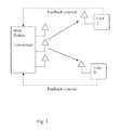
- FIG. 1 shows a downlink multiuser system with P transmit-antennas at the base station communicating with multiple mobile stations or devices.
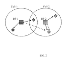
- FIG. 2 shows an exemplary multi-cell setup.
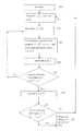
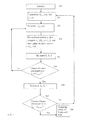
- FIG. 3 shows an exemplary beamforming design process which utilizes a derived beamforming structure and solves Karush-Kuhn-Tucker (KKT) equations for the non-convex optimization problem.
- KKT Karush-Kuhn-Tucker
- FIG. 1 shows a downlink multiuser system, with P transmit-antennas at the base station BS and 1 receive antenna at each user.
- a transmitter 110 transmits from P transmitting antennas 111 . 1 - 111 .P over a fading channel to multiple users.
- Each user's receive antenna is coupled to a receiver.
- a channel estimator provides an estimate of the channel corresponding to the propagation between the transmit antennas and the receive antenna, to the respective receiver.
- the channel estimate is also quantized and provided to the transmitter 110 via a feedback channel.
- FIG. 2 shows an exemplary multi-cell setup that handles co-channel interference mitigation in the downlink of a cellular system.
- all base stations are equipped with multiple transmit antennas and the mobiles are equipped with a single or multiple receive antenna each.
- Every base station employs linear beamforming or linear precoding to serve each one of its scheduled users or mobile devices on any resource slot and each scheduled user is served by only one base station.
- the association of each user to a particular base station (its serving base station) pre-determined.
- the base station of each cell serves its users through linear beamforming, or linear precoding.
- Each user receives useful (desired) signal from its serving base station (depicted using the solid line).
- Each user also receives interference (depicted as the dashed lines) from its serving base station as well as adjacent base stations.
- the interference includes all signals transmitted in the same resource slot (i.e., time/frequency/code slot) as the desired signal but which are intended for the other users.
- the system designs a set of beam vectors for a given set of channel estimates, which maximizes the weighted system sum-rate over a cluster of coordinated cells subject to per-base-station power constraints.
- the MISO system includes a downlink cellular network with universal frequency reuse where a cluster of it coordinated base stations simultaneously transmit on N orthogonal (in the time or frequency or code domain) resource slots during each scheduling interval.
- Each base station is equipped with P antennas and space-division multiple-access (SDMA) is employed to serve multiple mobiles (each having one receive antenna) on a resource slot.
- SDMA space-division multiple-access
- Each user is served by only one base station and coordinated base stations only exchange channel quality measurements and this scenario is referred to as a partially-connected cluster (PCC),
- PCC partially-connected cluster
- x m ⁇ ( n ) ⁇ k ⁇ B m ⁇ ( n ) ⁇ w m , k ⁇ ( n ) ⁇ b m , k ⁇ ( n ) ⁇ C P , where b m,k (n) is the complex symbol transmitted by base station m on slot n to user k ⁇ B m (n) using the beamforming vector w m,k (n) ⁇ C P .
- ⁇ n 1 N ⁇ ⁇ k ⁇ B m ⁇ ( n ) ⁇ ⁇ w m , k ⁇ 2 ⁇ P m , max , where P m,max is the maximum transmit power of base station m;
- ⁇ tilde over (h) ⁇ j,k (n) ⁇ C P be the channel matrix between base station j and user k on slot n, which includes small-scale fading, large-scale fading and path attenuation.
- the signal received by user k ⁇ B m (n) on slot n is given by
- ⁇ tilde over (z) ⁇ k (n) is the additive circularly-symmetric Gaussian noise with variance ⁇ k 2 (n): here, different noise levels account for different co-channel interference and different noise figures of the receivers. To simplify notation, the received signal is normalized by the noise standard deviation.
- the objective function to be maximized is the (istantaneous) weighted system sum-rate subject to per-base-station power constraints. Assuming Gaussian inputs and single-user detection at each mobile, the problem to
- the system first applies Lagrangian theory to derive the structure of the optimal beam-vectors; then, a process iteratively solves the set Karush-Kuhn-Tucker (KKT) conditions corresponding to the non-convex primal problem.
- KT Karush-Kuhn-Tucker
- a distributed implementation of the proposed algorithm is illustrated. Also, several approaches to choose the initial beam-vectors can be followed. Finally, an extension of the proposed algorithm to an equivalent MISO system is discussed.
- FIG. 3 shows an exemplary process which utilizes the derived beamforming structure and solves the Karush-Kuhn-Tucker (KKT) equations for the non-convex optimization problem.
- KKT Karush-Kuhn-Tucker
- the system is initialized by obtaining the estimates of all channels, the maximum transmit power of each base station and the priorities of the users.
- the values of the maximum number of iterations for the inner and outer loops L in,max and L out,max are selected.
- the system determines the scalars
- ⁇ î m,k (n), ⁇ circumflex over (L) ⁇ m,k (n) ⁇ denote the recent-most values of ⁇ i m,k (n), L m,k (n) ⁇ (i.e., the values most-recently updated).
- l in is incremented.
- a non-zero beam-vector which satisfies the above KKT conditions must be of the form w m,k (n) ⁇ (L m,k (n)+ ⁇ m ln 2I P ) ⁇ 1 h m,k (n).
- a non-zero beam-vector which satisfies the KKT conditions must be of the form w m,k (n) ⁇ L m,k ⁇ (n)h m,k (n).
- the procedure to solve the KKT system is as follows. If some previous feasible vectors ⁇ m,k (n) ⁇ are given, then ⁇ î m,k (n) ⁇ and ⁇ circumflex over (L) ⁇ m,k (n) ⁇ can be computed. The new values of ⁇ circumflex over ( ⁇ ) ⁇ m,k (n; ⁇ m ) ⁇ can now be computed as
- the new value of ⁇ m can be computed as the solution to
- the optimal set of dual variables ⁇ 1 , . . . , ⁇ M must satisfy the following inequalities:
- ⁇ m is set to zero: in this case, base station m does not use all available power for transmission.
- ICBF Iterative Coordinated Beam-Forming
- each base station can first update the quantities
- m ⁇ ( n ) ⁇ u ⁇ B m ⁇ ( n ) ⁇ w m , u H ⁇ ( n ) ⁇ G m , s ⁇ ( n ) ⁇ w m , u ⁇ ( n ) , l ⁇ m , s ⁇ B l ⁇ ( n ) , and pass them to the other coordinated base stations.
- base station m can determine
- ⁇ n 1 N ⁇ ⁇ k ⁇ B m ⁇ ( n ) ⁇ ⁇ w m , k ⁇ ( n ) ⁇ 2 ⁇ P m , max
- SOCP second-order cone program
- CM Beamforming The first is called Channel-Matched (CM) Beamforming. Neglecting in-cell and inter-cell interference, the system selects the initial beam vectors matched to the users' channel:
- the second is called In-Cell Zero-Forcing (ICZF) Beamforming.
- ITZF In-Cell Zero-Forcing
- the third alternative is the Maximum Signal-to-Leakage-plus-Noise Ratio (MSLNR) Beamforming.
- MSLNR Maximum Signal-to-Leakage-plus-Noise Ratio
- w m , k ⁇ ( n ) arg ⁇ ⁇ max x ⁇ C P ⁇ x H ⁇ G m , k ⁇ ( n ) ⁇ x x H ⁇ D m , k ⁇ ( n ) ⁇ x , s . t .
- This is a standard problem whose solution is the generalized eigenvector corresponding to the maximum generalized eigenvalue of the matrix pair (G m,k (n),D m,k (n)).
- ICBF-CM ICBF-CM
- ICBF-ICZF ICBF-MSLNR
- the coordinated base stations can act as a unique large array with distributed antenna elements and this case is the fully-connected cluster (FCC).
- FCC fully-connected cluster
- DPC dirty-paper coding
- the system can obtain a locally optimal solution.
- the ICBF process can be generalized to an FCC architecture with power polling and a weighted sum-power constraint across base stations. This may be attractive when the coordinated base stations pay unequal prices for transmit power: in this latter case, a larger weight can be given to a base station which has a stricter transmit power limitation.
- the ICBF process can be also generalized to an equivalent MISO system wherein each mobile user has multiple-receive antennas and performs rank-one receive beamforming before detection. Details are given in the following.
- N k be the number of receive antennas of user k. Then, the signal received by user k ⁇ B m (n) on slot n is given by
- the transmit linear filters and the receive linear filters can be iteratively designed as follows:
- the optimal receive filters must minimize the mean square estimation error and are given by:
- the MIMO system includes a downlink cellular network with universal frequency reuse where a cluster of M coordinated base stations simultaneously transmit on N orthogonal (in the time or frequency or code domain) resource slots during each scheduling interval.
- Each base station is equipped with P antennas and SDMA is employed to serve multiple mobiles (each having multiple receive antennas) on a resource slot.
- N k be the number of receive antennas of user k.
- Each user is served by only one base station and coordinated base stations only exchange channel quality measurements and this scenario is referred to as a partially-connected cluster (PCC).
- PCC partially-connected cluster
- x m ⁇ ( n ) ⁇ k ⁇ B m ⁇ ( n ) ⁇ W m , k ⁇ ( n ) ⁇ b m , k ⁇ ( n ) ⁇ C P , where b m,k (n) ⁇ C D m,k (n) is the complex symbol vector transmitted by base station m on slot n to user k ⁇ B m (n) using the precoder matrix W m,k (n) ⁇ C P ⁇ D m,k (n) , and 1 ⁇ D m,k (n) ⁇ P indicates the number of data stream delivered to user k ⁇ B m (n) on slot n by base station m.
- ⁇ n 1 N ⁇ ⁇ k ⁇ B m ⁇ ( n ) ⁇ tr ⁇ ( W m , k ⁇ ( n ) ⁇ W m , k H ⁇ ( n ) ) ⁇ P m , max , where tr(.) denotes the trace operation.
- ⁇ tilde over (H) ⁇ j,k (n) ⁇ C N k ⁇ P be the channel matrix between base station j and user k on slot n, which includes small-scale fading, large-scale fading and path attenuation.
- the signal received by user k ⁇ B m (n) on slot n is given by
- Q denote the set of all P ⁇ P positive semi-definite matrices in C P ⁇ P .
- Q is designed so as to maximize the (instantaneous) weighted system sum-rate, Assuming Gaussian inputs and single-user detection at each mobile, the problem to be solved is as follows:
- denotes the determinant of its matrix argument, ⁇ k (n)>0 is the priority assigned by the scheduler to user k on slot n. If ⁇ k (n) 1/(NM), the objective function becomes the network sum-rate (measured in bits/channel-use/slot/cell). More generally, the scheduler may adjust the coefficients ⁇ k (n) ⁇ over time to maintain proportional fairness among terminals.
- T is the vector of non-negative Lagrangian multipliers associated to the transmit power constraints and ⁇ m,k (n) ⁇ are the Lagrangian multipliers associated with the positive semi-definite constraints on ⁇ Q m,k (n) ⁇ .
- the precoder matrices can be obtained in a distributed way as follows.
- the system is initialized with a choice of ⁇ Q m,k (n) ⁇ using which ⁇ L m,k (n) ⁇ and ⁇ R m,k (n) ⁇ are determined.
- the system implements two loops. In the inner loop the system solves the following convex optimization problem at each base-station in, for a given ⁇ L m,k (n) ⁇ and ⁇ R m,k (n) ⁇ :
- ⁇ ⁇ n 1 N ⁇ ⁇ k ⁇ B m ⁇ ( n ) ⁇ tr ⁇ ( Q m , k ⁇ ( n ) ) ⁇ P m , max , Q m , k ⁇ ( n ) ⁇ Q _ , ⁇ ⁇ ⁇ k ⁇ B m ⁇ ( n ) , ⁇ n [ problem ⁇ ⁇ 2 ]
- the matrices ⁇ R m,k (n) ⁇ are updated and the problem [problem 2] is again solved at each base station.
- the inner loop (for a fixed set of leakage matrices ⁇ L m,k (n) ⁇ ) is repeated till convergence or a maximum number of iteration is achieved.
- the leakage matrices ⁇ L m,k (n) ⁇ are updated in the outer loop and the inner loop which involves updating ⁇ Q m,k (n) ⁇ using [problem 2] and ⁇ R m,k (n) ⁇ is initiated again.
- the outer loop itself is repeated till convergence or till a maximum number is reached.
- ICLP Iterative Coordinated Linear Precoding
- the coordinated base stations can act as a unique large array with distributed antenna elements and this case is the fully-connected cluster (FCC).
- FCC fully-connected cluster
- DPC dirty-paper coding
- the system can obtain a locally optimal solution.
- the system can extend the Maximum Signal-to-Leakage-plus-Noise Ratio (MSLNR) Beamforming to Maximum Signal-to-Leakage-plus-Noise Ratio (MSLNR) precoding.
- MSLNR Maximum Signal-to-Leakage-plus-Noise Ratio
- the precoder or equivalently the covariance matrix can be obtained by maximizing
- each user can first obtain estimates of the (effective) channel matrices using common pilots transmitted by its serving base station as well as the dominant interfering base stations.
- the system can use a common pilot which can be a reference signal whose form or structure is known in advance to all users. For instance, user k served by base station m can determine estimates of ⁇ H m,k (n) ⁇ for a few resource slots using common pilots transmitted by base station k on those slots and then interpolate to obtain channel estimates for the remaining slots.
- estimates of ⁇ H j,k (n) ⁇ corresponding to an interfering base station j can be Obtained using common pilots transmitted by base station j.
- the user should know the slots (or positions in time and/or frequency) where these common pilots are transmitted.
- the common pilots transmitted by adjacent base stations as well as those transmitted via different antennas of the same base station could be kept orthogonal using non-intersecting positions or via (near) orthogonal spreading sequences.
- the obtained estimates can then be quantized by the user and reported back to the serving base station via a uplink feedback channel.
- TDD time division duplex
- a key practical problem in coordinated beamforming and scheduling is that of the channel estimates getting outdated.
- the scheduling delay due to the delay between the time when a set of channel estimates are determined (by users or base stations) and the time when some or all of the users are scheduled for data transmission based on those estimates, henceforth referred to as the scheduling delay, the channels seen by the scheduled users could have significantly changed and consequently the rates assigned to them may not be achievable which can adversely affect the system throughput.
- the scheduling delay is a function of the backhaul latency associated with the inter-base station signaling as well as the scheduler implementations at the base stations.
- the average value of the scheduling delay can be tracked by each base station. In FDD systems, each base station can then broadcast its measured value to all the users that can be served by it, once in every several scheduling intervals. Upon receiving this value each user can employ any suitable prediction algorithm to obtain a predicted channel estimates. In particular, suppose the average scheduling delay value is D. Then, user k can first determine estimates of ⁇ H m,k (n) ⁇ , ⁇ H j,k (n) ⁇ j ⁇ m corresponding to time t and then obtain predicted estimates which are its estimates of channels for time t+D.
- the user can quantize and feedback these predicted channels.
- the UE can monitor the quality of its prediction over a time window. If it finds that the prediction quality is poor due to its mobility or other factors, it can inform its serving base station which can take appropriate action such as dropping it from the set of users that are served via coordinated beamforming. In TDD systems the prediction can be done by the base station itself. The predicted estimates are then used in the beamforming or precoding design procedure.
- the above embodiments address inter-cell interference mitigation in a MISO or MIMO wireless cellular network with universal frequency reuse.
- Each base station is equipped with multiple transmit antennas and space-division multiple-access (SDMA) is employed to serve multiple co-channel users.
- SDMA space-division multiple-access
- the set of beamforming vectors or precoding matrices across a cluster of coordinated cells and resource slots are designed so as to maximize the (instantaneous) weighted system sum-rate subject to per-base-station power constraints.
- each user is equipped with a single receive antenna and receives a single data stream from its serving base station.
- An Iterative Coordinated Beam-Forming (ICBF) algorithm is provided to design the transmit beamforming vectors.
- the ICBF algorithm can also be applied in an equivalent MISO network model wherein each user is equipped with multiple receive antennas and performs rank-one receive beamforming before detection.
- Numerical results indicate that the proposed ICBF technique significantly improves throughput with respect to uncoordinated beamforming strategies and achieves a large fraction of capacity. Also, power balancing across multiple resource slots is quite beneficial in a PCC scenario, while providing only marginal gains in an FCC scenario.
- each user may have multiple receive antennas and may receive multiple spatially-multiplexed data streams.
- An Iterative Coordinated Linear Precoding (ICLP) Algorithm is provided to design the transmit precoding matrices.
- the proposed ICBF and ICLP algorithms admit a distributed implementation and are general enough to be used both in a partially-connected cluster (PCC), wherein the coordinated base stations do not share data symbols and optimize their local beams based on the inter-cell channel gains only, and in a fully-connected cluster (FCC), wherein coordinated base stations act as a unique large array with distributed antenna elements.
- PCC partially-connected cluster
- FCC fully-connected cluster
- Distributed implementations with reduced signaling among base stations can also be done, and the system works robustly even with imperfect channel knowledge.
- the above process enhances a multi-cell wireless network with universal frequency reuse and treats the problem of co-channel interference mitigation in the downlink channel.
- each base station serves multiple single-antenna mobiles via space-division multiple-access (SDMA)
- SDMA space-division multiple-access
- the system jointly optimizes the linear beam-vectors or precoding matrices across a set of coordinated cells and resource slots: the objective function to be maximized is the weighted system sum-rate subject to per-base-station power constraints.
- the iterative process solves the Karush-Kuhn-Tucker (KKT) conditions of the non-convex primal problem.
- KKT Karush-Kuhn-Tucker
- Various approaches can be used to choose the initial beam-vectors, one of which maximizes the signal-to-leakage-plus-noise ratio. Simulation results are discussed in the incorporated by reference provisional application to assess the performance of the process.
Abstract
Description
-
- Bm(n) is the set of users served by base station m on slot n;
- N is the total number of orthogonal resource slots;
- M is the number of coordinated base stations;
- P is the number of transmit antennas at each base station;
- wm,k(n)εCP denotes the P-dimensional beam vector used by the base station m to serve user kεBm(n) on slot n;
- W={wm,k(n), kεBm(n), m=1, . . . , M, n=1, . . . , N} indicates the collection of all beam vectors;
- αk(n)>0 is the priority assigned by the scheduler to user k on slot n;
- Pm,max is the maximum transmit power of base station m;
- SINRm,k(n) is the signal-to-interference-plus-noise ratio for user k served by base station m on slot n and is given by
-
- with Gm,k(n)=hm,k(n)hm,k H(n)εCP×P.
- hm,k(n)εCP is the P-dimensional channel vector between base station j and user k and slot n (which includes small-scale fading, large scale fading and path attenuation) normalized by the standard deviation of the received noise.
The system can also determine
The determination of and λ1, . . . , λM and {{circumflex over (β)}m,k(n;λm), kεBm(n), n=1, . . . N} is:
where {circumflex over (T)}m,k(n;λm)={circumflex over (L)}m,k(n;λm)+(λm ln 2)IP, (•)† indicates the pseudo-inverse and x+=max{x,0} and where {îm,k(n),{circumflex over (L)}m,k(n)} denotes most recent values of {im,k(n),Lm,k(n)}. The system can update beam vectors as
w m,k(n)={circumflex over (β)}m,k(n;λ m){circumflex over (T)} m,k †(n;λ m)h m,k(n).
The system can select an initial feasible set of beam vectors. The initial feasible set can be selected after splitting power across the available slots. The system can perform channel-matched beamforming to select the initial feasible set of beam vectors. The system can also do in-cell zero-forcing beamforming to select the initial feasible set of beam vectors. Maximum signal-to-leakage-plus-noise ratio (MSLNR) beamforming can be used to select the initial feasible set of beam vectors. An equivalent MISO system can be provided wherein each mobile user has multiple-receive antennas and performs rank-one receive beamforming before detection. A multiple-input multiple-output (MIMO) system can be provided wherein each user is equipped with multiple receive antennas and receives multiple data streams from a serving base station via linear precoding. The optimal structure of the linear precoders in a MIMO system can be determined. A leakage matrix can be computed such as a leakage matrix Lm,k(n) where:
-
- Bm(n) is the set of users served by base station m on slot n;
- N is the total number of orthogonal resource slots;
- M is the number of coordinated base stations;
- P is the number of transmit antennas at each base station;
- Nk is the number of receive antennas of user k;
- Qj,u(n)=Wj,u(n)Wj,u H(n)εCP×P is a covariance matrix to be optimized;
- Wm,k(n)εCP×D
m,k (n), and 1≦Dm,k(n)≦P indicates the number of data stream delivered to user kεBm(n) on slot n by base station m; - Q={Qm,k(n)ε
Q ,kεBm(n), m=1, . . . , M, n=1, . . . N} indicates the collection of the positive-semidefinite covariance matrices; - αk(n)>0 is the priority assigned by the scheduler to user k on slot n;
- Pm,max is the maximum transmit power of base station in; and
- Hj,k(n)εCN
k ×P is the channel matrix between base station/and user k and slot n (which includes small-scale fading, large scale fading and path attenuation) normalized by the standard deviation of the received noise.
The system can solve a following convex optimization problem at each base-station in, for a given {Lm,k(n)} and {Rm,k(n)}:
The system can select an initial feasible set of positive semi-definite covariance matrices after splitting power across available slots. Maximum Signal-to-Leakage-plus-Noise Ratio (MSLNR) precoding can be used to select the initial feasible set of positive semi-definite covariance matrices.
where bm,k (n) is the complex symbol transmitted by base station m on slot n to user kεBm(n) using the beamforming vector wm,k(n)εCP. One system uses the assumption that E[|bm,k(n)|2]=1, E[bm
where Pm,max is the maximum transmit power of base station m;
where {tilde over (z)}k(n) is the additive circularly-symmetric Gaussian noise with variance σk 2(n): here, different noise levels account for different co-channel interference and different noise figures of the receivers. To simplify notation, the received signal is normalized by the noise standard deviation. Let yk(n)={tilde over (y)}k(n)/σk(n), zk(n)={tilde over (z)}k(n)/σk(n) and hk(n)={tilde over (h)}k(n)/σk(n), the following is obtained:
The objective function to be maximized is the (istantaneous) weighted system sum-rate subject to per-base-station power constraints. Assuming Gaussian inputs and single-user detection at each mobile, the problem to be solved is as follows:
where
-
- W={wm,k(n), kεBm(n), m=1, . . . , M, n=1, . . . N} indicates the collection of all beam vectors,
- αk(n)>0 is the priority assigned by the schedule to user k on slot n; if αk(n)=1/(NM), the objective function becomes the network sum-rate (measured in bits/channel-use/slot/cell); more generally, the scheduler may adjust the coefficients {αk(n)} over time to maintain proportional fairness among terminals.
- SINRm,k(n) is the signal-to-interference-plus-noise ratio for user k served by base station m on slot n and is given by
-
- with Gm,k(n)=hm,k(n)hm,k H(n)εCP×P.
where x+=max{x,0}, {circumflex over (T)}m,k(n;λm)={circumflex over (L)}m,k(n;λm)+(λm ln 2)IP and (•)† indicates the pseudo-inverse. Notice that {îm,k(n), {circumflex over (L)}m,k(n)} denote the recent-most values of {im,k(n), Lm,k(n)} (i.e., the values most-recently updated). Finally, the system updates the beam vectors {wm,k(n)} using
w m,k(n)={circumflex over (β)}m,k(n;λ m){circumflex over (T)} m,k †(n;λ m)h m,k(n).
h m,k H(n)w m,k(n)=0 and L m,k(n)w m,k(n)=0; C1
h m,k(n)εrange{L m,k(n)}. C2
If C1 is satisfied, then user kεBm(n) receives no information from the serving base station. On the other hand, if C2 holds and λm=0, a non-zero beam-vector which satisfies the KKT conditions must be of the form wm,k(n)∝Lm,k †(n)hm,k(n). Let Tm,k(n;λm)=Lm,k(n)+(λm ln 2)IP, then the optimal non-zero beam-vectors are of the form wm,k(n)=βm,k(n;λm)Tm,k †(n;λm)hm,k(n), kεBm(n), m=1, . . . , M, n=1, . . . N, where λm≧0 and βm,k(n;λm)>0 are constants to be determined. Also, λm=0 is feasible only if hm,k(n)εrange{Lm,k(n)} for kεBm(n) and n=1, . . . , N.
αk(n)h m,k(n)T m,k †(n;λ m)h m,k(n)=1+i m,k(n)+|βm,k(n;λ m)|2 |h m,k H(n)T m,k †(n;λ m)h m,k(n)|2 , kεB m(n), m=1, . . . , M, n=1, . . . N,
and
The procedure to solve the KKT system is as follows. If some previous feasible vectors {ŵm,k(n)} are given, then {îm,k(n)} and {{circumflex over (L)}m,k(n)} can be computed. The new values of {{circumflex over (β)}m,k(n;λm)} can now be computed as
for kεBm(n), m=1, . . . , M and n=1, . . . , N. The new value of λm can be computed as the solution to
In order to solve the above equation, notice that fm(n;λm) is a monotonic decreasing function of λm>0, for m=1, . . . , M. Moreover, the optimal set of dual variables λ1, . . . , λM must satisfy the following inequalities:
| 1: Initialize Lin,max, Lout,max, {wm,k(n), k ∈ βm(n), | ||
| m = 1, ..., M, n = 1, ..., N} | ||
| 2: lout = 0 | ||
| 3: repeat | ||
| 4: Compute {Lm,k(n), k ∈ βm(n), m = 1, ..., M, n = 1, ..., N} | ||
| 5: lin = 0 | ||
| 6: repeat | ||
| 7: Compute {lm,k(n), k ∈ βm(n), m = 1, ..., M, n = 1, ..., N} | ||
| 8: for m = 1 to M do | ||
| 9: Compute λm and {{circumflex over (β)}m,k(n, λm), k ∈ βm(n), n = 1, ..., N} | ||
| 10: Update {wm,k(n), k ∈ βm(n), n = 1, ..., N} | ||
| 11: end for | ||
| 12: lin = lin + 1 | ||
| 13: until convergence or lin = Lin,max | ||
| 14: lout = lout + 1 | ||
| 15: until convergence or lout = Lout,max | ||
where the terms im,k in(n) and im,k out(n) account for in-cell and out-cell interference, respectively. Similarly, the leakage matrix of terminal kεBm(n) on slot n becomes
where the terms Lm,k in(n) and Lm out(n) account for in-cell and out-cell leakages, respectively, and
and pass them to the other coordinated base stations. Upon receiving {im,k out,j(n)} from all j≠m and updating Pm,u(n), base station m can determine
which are then passed to the other coordinated base stations for the next iteration. The base station m needs the knowledge of the forward channels to the other coordinated cells and of the forward channels from the other coordinated cells.
For m=1, . . . , M, the above pro Item is equivalent to a second-order cone program (SOCP) convex optimization problem. Consequently, at each base station m an optimal set of beam vectors Wm can also be determined by using a SOCP solver.
for kεBm(n), m=1, . . . , M and n=1, . . . , N.
for kεBm(n), m=1, . . . , M and n=1, . . . , N. The proportionality constant is chosen to meet the power constraint. If P<Q, in-cell interference cannot be forced to zero anymore. However, the above equation is still a wise beamformer choice since it maximizes the ratio between the useful signal and the in-cell leakage for any user kεBm(n).
wm,k(n) is designed to maximize SLNRm,k(n) subject to a norm constraint:
This is a standard problem whose solution is the generalized eigenvector corresponding to the maximum generalized eigenvalue of the matrix pair (Gm,k(n),Dm,k(n)).
where {tilde over (H)}j,k(n)εCN
where hm,k H(n)=uk H(n)Hm,k(n)εC1×P, and zk(n)=uk H(n)qk(n)εC. This is an equivalent MISO signal model.
where u=k is not included in the summation and the proportionality constant is chosen to have ∥uk(n)∥=1.
where bm,k(n)εCD
where tr(.) denotes the trace operation.
where {tilde over (z)}k(n)εCN
where |.| denotes the determinant of its matrix argument, αk(n)>0 is the priority assigned by the scheduler to user k on slot n. If αk(n)=1/(NM), the objective function becomes the network sum-rate (measured in bits/channel-use/slot/cell). More generally, the scheduler may adjust the coefficients {αk(n)} over time to maintain proportional fairness among terminals.
where λ=(λ1, . . . , λM)T is the vector of non-negative Lagrangian multipliers associated to the transmit power constraints and {Δm,k(n)} are the Lagrangian multipliers associated with the positive semi-definite constraints on {Qm,k(n)}.
which accounts for the interference caused by base station m to other co-channel terminals on tone n when serving user kεBm(n). By setting the gradient of Λ(Q,λ) with respect to Qm,k(n) equal to zero, the following set of equalities are obtained:
L m,k(n)+ln 2(λM I P−Δm,k(n))=αk(n)H m,k H(n)(R m,k(n)+H m,k(n)Q m,k(n)H m,k H(n))−1 H m,k(n), kεB m(n), m=1, . . . , M, n=1, . . . , N
The above equations, along with the sum-power constraints in the prior equation, the positivity constraints and the following complementary slackness conditions:
tr(Q m,k(n)Δm,k(n))=0, kεB m(n), m=1, . . . , M, n=1, . . . , N,
Obtaining Channel State Information:
Claims (12)
Priority Applications (1)
| Application Number | Priority Date | Filing Date | Title |
|---|---|---|---|
| US13/414,244 US8488441B2 (en) | 2008-06-03 | 2012-03-07 | Coordinated linear beamforming in downlink multi-cell wireless networks |
Applications Claiming Priority (3)
| Application Number | Priority Date | Filing Date | Title |
|---|---|---|---|
| US5829508P | 2008-06-03 | 2008-06-03 | |
| US12/477,255 US8218422B2 (en) | 2008-06-03 | 2009-06-03 | Coordinated linear beamforming in downlink multi-cell wireless networks |
| US13/414,244 US8488441B2 (en) | 2008-06-03 | 2012-03-07 | Coordinated linear beamforming in downlink multi-cell wireless networks |
Related Parent Applications (1)
| Application Number | Title | Priority Date | Filing Date |
|---|---|---|---|
| US12/477,255 Division US8218422B2 (en) | 2008-06-03 | 2009-06-03 | Coordinated linear beamforming in downlink multi-cell wireless networks |
Publications (2)
| Publication Number | Publication Date |
|---|---|
| US20120170677A1 US20120170677A1 (en) | 2012-07-05 |
| US8488441B2 true US8488441B2 (en) | 2013-07-16 |
Family
ID=41379694
Family Applications (3)
| Application Number | Title | Priority Date | Filing Date |
|---|---|---|---|
| US12/477,255 Active 2030-11-14 US8218422B2 (en) | 2008-06-03 | 2009-06-03 | Coordinated linear beamforming in downlink multi-cell wireless networks |
| US13/414,244 Active US8488441B2 (en) | 2008-06-03 | 2012-03-07 | Coordinated linear beamforming in downlink multi-cell wireless networks |
| US13/414,202 Active US8488440B2 (en) | 2008-06-03 | 2012-03-07 | Coordinated linear beamforming in downlink multi-cell wireless networks |
Family Applications Before (1)
| Application Number | Title | Priority Date | Filing Date |
|---|---|---|---|
| US12/477,255 Active 2030-11-14 US8218422B2 (en) | 2008-06-03 | 2009-06-03 | Coordinated linear beamforming in downlink multi-cell wireless networks |
Family Applications After (1)
| Application Number | Title | Priority Date | Filing Date |
|---|---|---|---|
| US13/414,202 Active US8488440B2 (en) | 2008-06-03 | 2012-03-07 | Coordinated linear beamforming in downlink multi-cell wireless networks |
Country Status (1)
| Country | Link |
|---|---|
| US (3) | US8218422B2 (en) |
Cited By (3)
| Publication number | Priority date | Publication date | Assignee | Title |
|---|---|---|---|---|
| US20130044697A1 (en) * | 2011-08-17 | 2013-02-21 | Qualcomm Incorporated | Network coordination for improved interference cancellation |
| US20150117399A1 (en) * | 2013-10-29 | 2015-04-30 | Qualcomm Incorporated | Baton handover with receive diversity in td-scdma |
| US9521558B2 (en) | 2013-06-10 | 2016-12-13 | Samsung Electronics Co., Ltd. | Computing system with coordination mechanism and method of operation thereof |
Families Citing this family (83)
| Publication number | Priority date | Publication date | Assignee | Title |
|---|---|---|---|---|
| US8654815B1 (en) | 2004-04-02 | 2014-02-18 | Rearden, Llc | System and method for distributed antenna wireless communications |
| US10886979B2 (en) | 2004-04-02 | 2021-01-05 | Rearden, Llc | System and method for link adaptation in DIDO multicarrier systems |
| US11451275B2 (en) | 2004-04-02 | 2022-09-20 | Rearden, Llc | System and method for distributed antenna wireless communications |
| US10425134B2 (en) | 2004-04-02 | 2019-09-24 | Rearden, Llc | System and methods for planned evolution and obsolescence of multiuser spectrum |
| US10277290B2 (en) | 2004-04-02 | 2019-04-30 | Rearden, Llc | Systems and methods to exploit areas of coherence in wireless systems |
| US11309943B2 (en) | 2004-04-02 | 2022-04-19 | Rearden, Llc | System and methods for planned evolution and obsolescence of multiuser spectrum |
| US8542763B2 (en) | 2004-04-02 | 2013-09-24 | Rearden, Llc | Systems and methods to coordinate transmissions in distributed wireless systems via user clustering |
| US9819403B2 (en) | 2004-04-02 | 2017-11-14 | Rearden, Llc | System and method for managing handoff of a client between different distributed-input-distributed-output (DIDO) networks based on detected velocity of the client |
| US10187133B2 (en) | 2004-04-02 | 2019-01-22 | Rearden, Llc | System and method for power control and antenna grouping in a distributed-input-distributed-output (DIDO) network |
| US11394436B2 (en) | 2004-04-02 | 2022-07-19 | Rearden, Llc | System and method for distributed antenna wireless communications |
| US10985811B2 (en) | 2004-04-02 | 2021-04-20 | Rearden, Llc | System and method for distributed antenna wireless communications |
| US10749582B2 (en) | 2004-04-02 | 2020-08-18 | Rearden, Llc | Systems and methods to coordinate transmissions in distributed wireless systems via user clustering |
| US10200094B2 (en) | 2004-04-02 | 2019-02-05 | Rearden, Llc | Interference management, handoff, power control and link adaptation in distributed-input distributed-output (DIDO) communication systems |
| US9826537B2 (en) | 2004-04-02 | 2017-11-21 | Rearden, Llc | System and method for managing inter-cluster handoff of clients which traverse multiple DIDO clusters |
| US9312929B2 (en) | 2004-04-02 | 2016-04-12 | Rearden, Llc | System and methods to compensate for Doppler effects in multi-user (MU) multiple antenna systems (MAS) |
| US9685997B2 (en) | 2007-08-20 | 2017-06-20 | Rearden, Llc | Systems and methods to enhance spatial diversity in distributed-input distributed-output wireless systems |
| US7965783B2 (en) * | 2007-01-08 | 2011-06-21 | Cisco Technology, Inc. | Method and system for transmitting data streams via a beamformed MIMO channel |
| US8218422B2 (en) * | 2008-06-03 | 2012-07-10 | Nec Laboratories America, Inc. | Coordinated linear beamforming in downlink multi-cell wireless networks |
| US8660497B1 (en) | 2009-08-18 | 2014-02-25 | Marvell International Ltd. | Beamsteering in a spatial division multiple access (SDMA) system |
| US9137802B2 (en) * | 2009-08-18 | 2015-09-15 | Qualcomm Incorporated | DL MU-MIMO operation in LTE-A |
| US8385454B2 (en) * | 2009-09-09 | 2013-02-26 | Nec Laboratories America, Inc. | Robust linear precoder designs for multi-cell downlink transmission |
| US9031080B2 (en) * | 2009-12-23 | 2015-05-12 | Telefonaktiebolaget L M Ericsson (Publ) | Rate allocation scheme for coordinated multipoint transmission |
| KR101576915B1 (en) * | 2009-12-28 | 2015-12-14 | 삼성전자주식회사 | Communication system of using joint leakage suppression scheme with low complexity |
| KR101670946B1 (en) * | 2010-01-18 | 2016-10-31 | 삼성전자주식회사 | Mrthod for precoding in a mullti cell multi user systems and communication apparatus |
| US9231795B2 (en) * | 2010-01-18 | 2016-01-05 | Samsung Electronics Co., Ltd. | Communication apparatus and precoding method based on multiple cells and multiple users |
| KR101728544B1 (en) * | 2010-01-22 | 2017-04-19 | 삼성전자주식회사 | Method and apparatus for scheduling in multiple-input multiple-output communication system |
| JP2011259241A (en) * | 2010-06-09 | 2011-12-22 | Ntt Docomo Inc | Inter-base station cooperation mimo-transmission method and base station device |
| EP2583385B1 (en) | 2010-06-16 | 2018-04-18 | Marvell World Trade Ltd. | Alternate feedback types for downlink multiple user mimo configurations |
| WO2012003627A1 (en) * | 2010-07-06 | 2012-01-12 | Huawei Technologies Co., Ltd. | Method for communicating with a user equipment using plurality of transmit antennas |
| EP2410705B1 (en) * | 2010-07-20 | 2015-08-19 | NTT DoCoMo, Inc. | Apparatus and method for calculating receive parameters for an MIMO system |
| EP3614635A1 (en) | 2010-08-10 | 2020-02-26 | Marvell World Trade Ltd. | Sub-band feedback for beamforming on downlink multiple user mimo configurations |
| KR20120031700A (en) | 2010-09-27 | 2012-04-04 | 삼성전자주식회사 | Method and apparatus of interference aligning using feedforward index in hierarchical cell communication system |
| KR20120032777A (en) | 2010-09-29 | 2012-04-06 | 삼성전자주식회사 | Method and apparatus for determining downlink beamforming vectors in hierarchical cell communication system |
| WO2012149576A1 (en) * | 2011-04-28 | 2012-11-01 | The Trustees Of Columbia University In The City Of New York | Systems, methods, and media for selecting antennas and beamformers |
| US8797966B2 (en) | 2011-09-23 | 2014-08-05 | Ofinno Technologies, Llc | Channel state information transmission |
| US8848698B2 (en) * | 2011-10-22 | 2014-09-30 | Lg Electronics Inc. | Scheduling method in multiple access system and apparatus using the same |
| US8817685B2 (en) * | 2011-10-24 | 2014-08-26 | Nokia Corporation | Energy-efficient underlay device-to-multidevice communications with interference suppression |
| US8885569B2 (en) | 2011-12-19 | 2014-11-11 | Ofinno Technologies, Llc | Beamforming signaling in a wireless network |
| KR101922597B1 (en) * | 2011-12-27 | 2019-02-21 | 삼성전자주식회사 | Method and apparatus for transmitting and receiving channel state information reference signal for massive multi input multi output system based wireless communication systems |
| US8565181B2 (en) * | 2012-02-06 | 2013-10-22 | Neocific, Inc. | Methods and apparatus for multi-carrier communications with efficient control signaling |
| CN102664665A (en) * | 2012-03-23 | 2012-09-12 | 东南大学 | Alternative-optimization and rate-maximization multi-point cooperation wave beam forming method |
| CN103634036B (en) * | 2012-08-27 | 2017-10-27 | 华为技术有限公司 | Distributed multiple cell multi-user beam-forming method, emitter and related system |
| US9337973B2 (en) | 2012-09-11 | 2016-05-10 | Industrial Technology Research Institute | Method of cooperative MIMO wireless communication and base station using the same |
| CN102905320B (en) * | 2012-09-24 | 2015-04-01 | 上海交通大学 | Monotone optimization method for maximizing multi-cell downlink weighting and rate |
| US9467871B2 (en) | 2012-09-28 | 2016-10-11 | Qualcomm Incorporated | Iterative coordinated beamforming systems and methods |
| US11189917B2 (en) | 2014-04-16 | 2021-11-30 | Rearden, Llc | Systems and methods for distributing radioheads |
| US11050468B2 (en) | 2014-04-16 | 2021-06-29 | Rearden, Llc | Systems and methods for mitigating interference within actively used spectrum |
| US11190947B2 (en) | 2014-04-16 | 2021-11-30 | Rearden, Llc | Systems and methods for concurrent spectrum usage within actively used spectrum |
| US10194346B2 (en) * | 2012-11-26 | 2019-01-29 | Rearden, Llc | Systems and methods for exploiting inter-cell multiplexing gain in wireless cellular systems via distributed input distributed output technology |
| WO2014088003A1 (en) * | 2012-12-06 | 2014-06-12 | シャープ株式会社 | Base station apparatus, terminal apparatus, wireless communication system and integrated circuit |
| CN103188002B (en) * | 2013-01-21 | 2015-09-02 | 厦门蓝帝电子科技有限公司 | A kind of multi-antenna multi-user distributed system beamforming strategy |
| US9923657B2 (en) | 2013-03-12 | 2018-03-20 | Rearden, Llc | Systems and methods for exploiting inter-cell multiplexing gain in wireless cellular systems via distributed input distributed output technology |
| US10488535B2 (en) | 2013-03-12 | 2019-11-26 | Rearden, Llc | Apparatus and method for capturing still images and video using diffraction coded imaging techniques |
| US10164698B2 (en) | 2013-03-12 | 2018-12-25 | Rearden, Llc | Systems and methods for exploiting inter-cell multiplexing gain in wireless cellular systems via distributed input distributed output technology |
| US9973246B2 (en) | 2013-03-12 | 2018-05-15 | Rearden, Llc | Systems and methods for exploiting inter-cell multiplexing gain in wireless cellular systems via distributed input distributed output technology |
| US10547358B2 (en) | 2013-03-15 | 2020-01-28 | Rearden, Llc | Systems and methods for radio frequency calibration exploiting channel reciprocity in distributed input distributed output wireless communications |
| KR101994325B1 (en) * | 2013-05-31 | 2019-09-30 | 삼성전자주식회사 | Array antenna apparatus and control method thereof in communication system |
| CN103684561B (en) * | 2013-12-04 | 2017-07-11 | 上海交通大学 | In multi-cell system there is the distributed precoding method of Bounded Errors in channel information |
| CN104767552A (en) * | 2014-01-06 | 2015-07-08 | 中兴通讯股份有限公司 | Method of realizing beamforming coordination and base station |
| US11290162B2 (en) | 2014-04-16 | 2022-03-29 | Rearden, Llc | Systems and methods for mitigating interference within actively used spectrum |
| WO2015198810A1 (en) * | 2014-06-25 | 2015-12-30 | 京セラ株式会社 | Wireless communications device, wireless communications system, and wireless communications method |
| US9503911B2 (en) * | 2014-07-24 | 2016-11-22 | Huawei Technologies Co., Ltd. | System and method for coordinated beamforming for overlapping basic service set in WLAN |
| US9628999B2 (en) | 2014-07-24 | 2017-04-18 | Huawei Technologies Co., Ltd. | System and methods for enabling coordinated beamforming in overlapping basic service set in WLAN |
| WO2016076611A1 (en) * | 2014-11-10 | 2016-05-19 | 엘지전자 주식회사 | Data transmission and reception method and device using caching in wireless communication system performing comp |
| CN104393956B (en) * | 2014-11-26 | 2017-12-05 | 北京邮电大学 | One kind is used for wireless portable communications system and maximized and speed method for precoding |
| CN106788634A (en) * | 2017-01-13 | 2017-05-31 | 上海海事大学 | Robust transceiver design method in multiple cell MIMO interference channels |
| FR3064853B1 (en) * | 2017-03-31 | 2019-03-22 | Continental Automotive France | METHOD AND SENSOR FOR DETECTING THE PRESENCE OF COCANAL INTERFERENCE |
| FR3067189B1 (en) * | 2017-06-01 | 2020-06-12 | Continental Automotive France | METHOD FOR THE SPATIAL AND TIME SUPPRESSION OF MULTI-PATH INTERFERENCE FOR A FREQUENCY MODULATED RADIO SIGNAL RECEIVER |
| FR3067186B1 (en) * | 2017-06-01 | 2019-06-21 | Continental Automotive France | METHOD FOR REMOVING MULTI-PATH SIGNALS FOR FREQUENCY MODULATED RADIO SIGNAL RECEIVER |
| CN107171704B (en) * | 2017-06-09 | 2020-04-14 | 北京邮电大学 | Uplink power control method and device for large-scale MIMO system |
| CN108282886B (en) * | 2017-12-20 | 2023-04-18 | 南京邮电大学 | User scheduling and energy efficiency combined optimization method in MIMO-OFDMA downlink channel |
| CN108964733B (en) * | 2018-06-20 | 2022-04-15 | 南京邮电大学 | Beam forming method and heterogeneous cloud wireless access network based on same |
| CN108718205B (en) * | 2018-07-11 | 2020-11-06 | 北京大学 | Cooperative transmission beam forming method and communication system suitable for full-duplex cellular network |
| CN108964730A (en) * | 2018-07-16 | 2018-12-07 | 南京理工大学 | The approximate linear pre-coding method of convex row is based in the modulating system of safe space |
| US11363466B2 (en) * | 2020-01-22 | 2022-06-14 | Charter Communications Operating, Llc | Methods and apparatus for antenna optimization in a quasi-licensed wireless system |
| CN112491472B (en) * | 2020-12-03 | 2022-02-01 | 东南大学 | Method for optimizing zero forcing precoding matrix of visible light communication system |
| US11490329B1 (en) | 2021-04-29 | 2022-11-01 | T-Mobile Usa, Inc. | Determining a cell to which to connect user equipment |
| CN113315547A (en) * | 2021-05-28 | 2021-08-27 | 北京邮电大学 | Robust joint transmission beam optimization method for intelligent reflecting surface assisted multiple cells |
| CN113537722B (en) * | 2021-06-23 | 2023-08-01 | 西安交通大学 | Scheduling planning method and application |
| CN114172549B (en) * | 2021-12-07 | 2022-06-24 | 东南大学 | Sky wave large-scale MIMO communication downlink transmission method |
| CN114389658B (en) * | 2021-12-31 | 2023-05-30 | 南京邮电大学 | Uplink power optimization method for zero-forcing reception cellular-removing large-scale MIMO system |
| CN114584188B (en) * | 2022-01-13 | 2023-06-27 | 中国人民解放军陆军工程大学 | Anti-eavesdrop communication method based on multi-station cooperation |
| CN114793127B (en) * | 2022-04-21 | 2023-06-23 | 暨南大学 | Dual-function radar communication method, device, computer equipment and storage medium |
Citations (4)
| Publication number | Priority date | Publication date | Assignee | Title |
|---|---|---|---|---|
| US20090111473A1 (en) * | 2007-10-31 | 2009-04-30 | Zhifeng Tao | Cooperative Communication in Wireless Cellular Networks |
| US20090180405A1 (en) * | 2008-01-15 | 2009-07-16 | Ashikhmin Alexei E | MIMO Communication System with User Scheduling and Modified Precoding Based on Channel Vector Magnitudes |
| US20100111226A1 (en) * | 2007-03-12 | 2010-05-06 | Hyun Soo Ko | Method for transmitting control information in multiple antenna system |
| US8218422B2 (en) * | 2008-06-03 | 2012-07-10 | Nec Laboratories America, Inc. | Coordinated linear beamforming in downlink multi-cell wireless networks |
Family Cites Families (5)
| Publication number | Priority date | Publication date | Assignee | Title |
|---|---|---|---|---|
| US8144666B2 (en) * | 2005-05-13 | 2012-03-27 | Rockstar Bidco Lp | Downlink beamforming for broadband wireless networks |
| US20070153754A1 (en) * | 2005-12-29 | 2007-07-05 | Nir Shapira | Method, apparatus and system of spatial division multiple access communication in a wireless local area network |
| US7778598B2 (en) * | 2007-01-22 | 2010-08-17 | Mitsubishi Electric Research Laboratories, Inc. | Asymmetric cooperation in downlink cellular networks with relay stations |
| US20080298486A1 (en) * | 2007-06-04 | 2008-12-04 | Nec Laboratories America, Inc. | Multi-cell interference mitigation via coordinated scheduling and power allocation in downlink odma networks |
| US9025537B2 (en) * | 2008-02-12 | 2015-05-05 | Centre Of Excellence In Wireless Technology | Inter-cell interference mitigation using limited feedback in cellular networks |
-
2009
- 2009-06-03 US US12/477,255 patent/US8218422B2/en active Active
-
2012
- 2012-03-07 US US13/414,244 patent/US8488441B2/en active Active
- 2012-03-07 US US13/414,202 patent/US8488440B2/en active Active
Patent Citations (4)
| Publication number | Priority date | Publication date | Assignee | Title |
|---|---|---|---|---|
| US20100111226A1 (en) * | 2007-03-12 | 2010-05-06 | Hyun Soo Ko | Method for transmitting control information in multiple antenna system |
| US20090111473A1 (en) * | 2007-10-31 | 2009-04-30 | Zhifeng Tao | Cooperative Communication in Wireless Cellular Networks |
| US20090180405A1 (en) * | 2008-01-15 | 2009-07-16 | Ashikhmin Alexei E | MIMO Communication System with User Scheduling and Modified Precoding Based on Channel Vector Magnitudes |
| US8218422B2 (en) * | 2008-06-03 | 2012-07-10 | Nec Laboratories America, Inc. | Coordinated linear beamforming in downlink multi-cell wireless networks |
Cited By (4)
| Publication number | Priority date | Publication date | Assignee | Title |
|---|---|---|---|---|
| US20130044697A1 (en) * | 2011-08-17 | 2013-02-21 | Qualcomm Incorporated | Network coordination for improved interference cancellation |
| US9497765B2 (en) * | 2011-08-17 | 2016-11-15 | Qualcomm Incorporated | Network coordination for improved interference cancellation |
| US9521558B2 (en) | 2013-06-10 | 2016-12-13 | Samsung Electronics Co., Ltd. | Computing system with coordination mechanism and method of operation thereof |
| US20150117399A1 (en) * | 2013-10-29 | 2015-04-30 | Qualcomm Incorporated | Baton handover with receive diversity in td-scdma |
Also Published As
| Publication number | Publication date |
|---|---|
| US20120170677A1 (en) | 2012-07-05 |
| US20120163332A1 (en) | 2012-06-28 |
| US20090296650A1 (en) | 2009-12-03 |
| US8218422B2 (en) | 2012-07-10 |
| US8488440B2 (en) | 2013-07-16 |
Similar Documents
| Publication | Publication Date | Title |
|---|---|---|
| US8488441B2 (en) | Coordinated linear beamforming in downlink multi-cell wireless networks | |
| Atzeni et al. | Distributed precoding design via over-the-air signaling for cell-free massive MIMO | |
| US9407343B2 (en) | Method and apparatus for mitigating downlink interference | |
| EP2227869B1 (en) | Method for reducing inter-cell interference | |
| EP2242187B1 (en) | Method and device for data processing in a communication network | |
| KR101478843B1 (en) | Method of transmitting data in coordinated multi-cell wireless communication system | |
| EP2291932B1 (en) | Downlink wireless transmission schemes with inter-cell interference mitigation | |
| EP2292037B1 (en) | Inter-cell interference avoidance for downlink transmission | |
| US9025537B2 (en) | Inter-cell interference mitigation using limited feedback in cellular networks | |
| US8467468B2 (en) | Transmitting and receiving apparatus having plural antenna in multi-user environments and method thereof | |
| US20120207145A1 (en) | Method and apparatus for downlink transmission based on mimo precoding in wireless communication system employing distributed antenna systems | |
| US8634488B2 (en) | Data transmission method and apparatus based on joint space division multiple access technology in collaborative downlink MIMO system | |
| WO2008004609A1 (en) | Wireless communication system and communication control method | |
| KR101115785B1 (en) | Apparatus and method of cooperative interference mitigation and resource management in wireless dual-hop relay systems with multiple antennas | |
| CN104854799A (en) | Transmission power distribution for MIMO communications when multiplicative noise limited | |
| US9635572B2 (en) | Method for coordinating interference in an uplink interference channel for a terminal in a wireless communication system | |
| US8599952B2 (en) | MU-COMP channel state normalization measure quantization and transmission | |
| Jang et al. | Transmit beamforming based inter-cell interference alignment and user selection with CoMP | |
| Gouda et al. | Distributed precoding design for cell-free massive MIMO systems | |
| Apelfröjd et al. | Design and measurement-based evaluations of coherent JT CoMP: a study of precoding, user grouping and resource allocation using predicted CSI | |
| Laiyemo et al. | Transmission strategies for throughput maximization in high-speed-train communications: From theoretical study to practical algorithms | |
| Björnson et al. | Optimality properties and low-complexity solutions to coordinated multicell transmission | |
| CN103188006A (en) | Transmission method and transmission system of downlink coordinated multiple points | |
| Jayasinghe et al. | Direct beamformer estimation for dynamic TDD networks with forward-backward training | |
| Tabikh et al. | Beamforming design with combined channel estimate and covariance CSIT via random matrix theory |
Legal Events
| Date | Code | Title | Description |
|---|---|---|---|
| STCF | Information on status: patent grant |
Free format text: PATENTED CASE |
|
| AS | Assignment |
Owner name: NEC CORPORATION, JAPAN Free format text: ASSIGNMENT OF ASSIGNORS INTEREST;ASSIGNOR:NEC LABORATORIES AMERICA, INC.;REEL/FRAME:031998/0667 Effective date: 20140113 |
|
| FPAY | Fee payment |
Year of fee payment: 4 |
|
| AS | Assignment |
Owner name: NEC CORPORATION, JAPAN Free format text: CORRECTIVE ASSIGNMENT TO CORRECT THE REMOVE 8538896 AND ADD 8583896 PREVIOUSLY RECORDED ON REEL 031998 FRAME 0667. ASSIGNOR(S) HEREBY CONFIRMS THE ASSIGNMENT;ASSIGNOR:NEC LABORATORIES AMERICA, INC.;REEL/FRAME:042754/0703 Effective date: 20140113 |
|
| MAFP | Maintenance fee payment |
Free format text: PAYMENT OF MAINTENANCE FEE, 8TH YEAR, LARGE ENTITY (ORIGINAL EVENT CODE: M1552); ENTITY STATUS OF PATENT OWNER: LARGE ENTITY Year of fee payment: 8 |