US8453336B2 - Peep sight assembly with removable inserts for archery bows - Google Patents
Peep sight assembly with removable inserts for archery bows Download PDFInfo
- Publication number
- US8453336B2 US8453336B2 US13/250,603 US201113250603A US8453336B2 US 8453336 B2 US8453336 B2 US 8453336B2 US 201113250603 A US201113250603 A US 201113250603A US 8453336 B2 US8453336 B2 US 8453336B2
- Authority
- US
- United States
- Prior art keywords
- peep sight
- sight
- insert
- peep
- housing
- Prior art date
- Legal status (The legal status is an assumption and is not a legal conclusion. Google has not performed a legal analysis and makes no representation as to the accuracy of the status listed.)
- Active, expires
Links
Images


Classifications
-
- F—MECHANICAL ENGINEERING; LIGHTING; HEATING; WEAPONS; BLASTING
- F41—WEAPONS
- F41G—WEAPON SIGHTS; AIMING
- F41G1/00—Sighting devices
- F41G1/46—Sighting devices for particular applications
- F41G1/467—Sighting devices for particular applications for bows
Definitions
- This invention relates generally to peep sights for archery bows, and more particularly to a peep sight assembly having interchangeable inserts with different aperture sizes for accommodating different users and shooting conditions.
- peep sight In the field of archery, it is well-known to provide a peep sight on the string above the nocking point of an archery bow.
- the peep sight must be properly located so that a user may accurately sight in the bow sight with respect to a distant target while in a shooting stance.
- the particular peep sight position is largely dependent on the archer's anchor point when the bow is fully drawn in relation to his or her aiming eye, which may be different for each archer.
- a peep sight assembly for an archery bow includes a peep sight housing adapted for connection to a bow string of the archery bow and a peep sight insert for changing the size of the sight aperture.
- the peep sight housing has front and rear surfaces with a first inner surface located therebetween to define a sight aperture with a first dimension.
- the peep sight insert has a rear flange adapted to abut the rear surface, a front flange adapted to abut the front surface, and a continuous side wall extending between the front and rear flanges to define a sight aperture with a second dimension that is smaller than the first dimension.
- a peep sight insert for installation into an aperture of a peep sight for reducing an aperture size of the peep sight includes a rear flange, a front flange, and a continuous side wall extending between the rear and front flanges to define a sight aperture.
- the continuous side wall includes a first outer sloped surface extending inwardly and forwardly from the rear flange; and a second outer sloped surface extending inwardly and rearwardly from the front flange.
- a peep sight kit includes a peep sight housing adapted for connection to a bow string of an archery bow and a plurality of interchangeable peep sight inserts for installation in the peep sight housing.
- the peep sight housing has rear and front surfaces and a sight aperture located therebetween.
- a first inner sloped surface extends inwardly and rearwardly from the front surface, and a second inner sloped surface extends inwardly and forwardly from the rear surface.
- Each peep sight insert has a sight aperture that is different in size than the other sight apertures of the peep sight kit.
- Each peep sight insert includes a rear flange, a front flange, and a continuous side wall extending between the rear and front flanges to define the sight aperture.
- the continuous side wall has a first outer sloped surface that extends inwardly and forwardly from the rear flange and is adapted to abut the first inner sloped surface, and a second outer sloped surface that extends inwardly and rearwardly from the front flange and is adapted to abut the second inner sloped surface.
- FIG. 1 is an isometric view of a peep sight assembly in accordance with the present invention connected to a bow string;
- FIG. 2 is an enlarged isometric view of the peep sight assembly
- FIG. 3 is an exploded isometric view thereof
- FIG. 4 is a rear elevational view thereof
- FIG. 5 is a side elevational view thereof
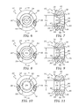
- FIG. 6 is a front elevational view of the peep sight assembly with a small aperture insert
- FIG. 7 is a sectional view taken along line 7 - 7 of FIG. 6 ;
- FIG. 8 is a front elevational view of the peep sight assembly with a medium aperture insert
- FIG. 9 is a sectional view taken along line 9 - 9 of FIG. 8 ;
- FIG. 10 is a front elevational view of the peep sight assembly with a large aperture insert
- FIG. 11 is a sectional view taken along line 11 - 11 of FIG. 10 ;
- FIG. 12 is an isometric view of a peep sight insert having a particular aperture size in accordance with a further embodiment of the invention.
- FIG. 13 is a top plan view thereof
- FIG. 14 is a side elevational view thereof
- FIG. 15 is a sectional view of the peep sight insert taken along line 15 - 15 of FIG. 13 ;
- FIG. 16 is an isometric view of a peep sight insert having a different aperture size in accordance with the invention.
- FIG. 17 is a sectional view of the insert of FIG. 16 ;
- FIG. 18 is an isometric view of a peep sight kit having a peep sight and a number of differently configured peep sight inserts;
- FIGS. 19-21 show the steps, in a side elevational view, for installing a peep sight insert into a peep sight housing mounted on a bow string;
- FIGS. 22-24 show the steps, in a side elevational view, for removing a peep sight insert from a peep sight housing mounted on a bow string.
- a peep sight assembly 10 in accordance with the present invention is shown connected to a bow string 12 of an archery bow (not shown).
- the peep sight assembly 10 can be adapted for use with any type of bow including, but not limited to, recurve bows, reflex bows, longbows, compound bows, and so on.
- the bow string 12 is of conventional construction and typically includes multiple elongate strands 14 of any suitable material used to make bowstrings.
- a peep sight assembly 10 in accordance with the present invention is shown positioned between the strands 14 in FIG. 1 .
- the strands are sufficiently flexible, at least when the bow string is relaxed or non-stressed, to permit the creation of an opening 16 for receiving the peep sight assembly 10 .
- Sight holders 18 preferably encircle the strands 14 to secure the peep sight to the string 12 in a conventional manner.
- the sight holders are in the form of elongate cords that are tied as nail knots around the strands 14 of the string 12 . It will be understood that the nail knots may be replaced with individual clamps, slidable crimping members or the like.
- the peep sight assembly 10 preferably includes a peep sight housing 20 with a sight aperture 22 and at least one peep sight insert 24 that is removably positioned within the sight aperture.
- the peep sight housing 20 is preferably constructed of a rigid material, such as aluminum or other metal, plastic and/or ceramic materials, and preferably includes an annular body 26 with a rear face 28 , a front face 30 , and a continuous side surface 32 extending between the rear and front faces.
- a groove 34 is formed in the side surface 32 .
- the groove 34 extends continuously around the periphery of the annular body 26 .
- Slots 36 , 38 are preferably located on opposite sides of the annular body 26 .
- Each slot preferably intersects the circular groove 34 and extends downwardly from the front surface 30 to the rear surface 28 of the annular body 26 , as best shown in FIG. 5 .
- Each slot 36 , 38 is adapted for receiving the strands 14 of the bow string 12 when the peep sight housing 20 is mounted on the bow string.
- a cord or band 39 ( FIG. 1 ) can be located in the groove 34 and wraps around the strands 14 in the slots 36 , 38 to further secure the peep sight housing 20 to the bow string 12 .
- the sight aperture 22 of the peep sight housing 20 is preferably coaxial with a central axis 40 ( FIG. 3 ) of the annular body 26 and preferably includes a first inner surface 42 , a second inner surface 44 that slopes inwardly from the rear face 28 toward the first inner surface 42 , and a third inner surface 46 that slopes inwardly from the front face 30 to the first inner surface 42 .
- the first inner surface 42 preferably extends coaxially with the central axis 40 with the second and third inner surfaces sloping away from the first inner surface.
- the first inner surface 42 forms a sight opening with a predetermined aperture size or diameter D 1 ( FIG. 7 ).
- the peep sight housing 20 can be used without the peep sight insert 24 during aiming.
- the size of the sight aperture 22 is selected to coincide with a largest aperture size that may be needed for most archers and/or archery bow configurations.
- the first inner surface 46 can be of any width, including zero width which may be in the form of a peak or circular line resulting from the intersection of the second and third inner surfaces.
- the peep sight insert 24 preferably includes an annular body 50 with a rear flange 52 , a front flange 54 , and a continuous side wall 56 extending between the rear and front flanges to form a sight aperture 58 that is smaller than the sight aperture 22 previously described.
- the sight aperture 58 is preferably coaxial with the central axis 40 ( FIG. 3 ) of the annular body 26 . In this manner, the installation and removal of the peep sight insert does not affect the rear aim point of the bow.
- the continuous side wall 56 preferably includes a first inner surface 60 ( FIG.
- the first inner surface 60 preferably extends coaxially with the central axis 40 with the second and third inner surfaces 62 , 64 sloping away from the first inner surface.
- the first inner surface 60 forms a sight opening with a predetermined aperture size or diameter D 2 that is smaller than the diameter D 1 of the sight aperture 22 . It will be understood that the first inner surface 60 can be of any width, including zero width which may be in the form of a peak or circular line resulting from the intersection of the second and third inner surfaces 62 , 64 .
- the continuous side wall 56 also preferably includes a first outer surface 66 , a second outer surface 68 that slopes inwardly from the rear flange 52 toward the first outer surface 66 , and a third outer surface 70 that slopes inwardly from the front flange 54 and the first outer surface 66 .
- the slope of the second and third outer surfaces may be different from the slope of the second and third inner surfaces of the peep sight insert 24 .
- the slope of the second and third outer surfaces preferably corresponds to the slope of the second and third inner surfaces of the peep sight housing.
- the first, second and third outer surfaces of the peep sight insert 24 respectively engage the first, second and third inner surfaces of the peep sight housing 20 , with the rear flange 52 and front flange 54 of the peep sight insert 24 respectively abutting the rear surface 26 and front surface 30 of the peep sight housing 20 .
- the peep sight insert 24 is constructed as a unitary member during the forming process, and is formed of a resilient material, such as rubber, so that the insert 24 can be easily installed and removed by an archer or other person while in the field or other location without tools.
- the material has a Shore A hardness in the range of about 40 to 100 durometer, and more preferably about 70 durometer.
- the sloped outer surfaces 68 and 70 increase the surface area over a cylindrical or straight outer surface, providing more gripping area between the sloped surfaces of the peep sight housing 20 and the sloped surfaces of the peep sight insert 24 to thereby more securely anchor the insert to the peep sight housing without the need of tools, clamps, adhesives or other secondary securing means.
- the outer sloped surfaces 68 , 70 of the peep sight insert 24 are preferably of a uniform matte finish to increase the friction fit between the insert and peep sight housing.
- the front and rear flanges together with the sloped surfaces and the surface finish on the outer sloped surfaces 68 , 70 of the peep sight insert 24 contribute to firmly anchoring the peep sight insert within the peep sight housing.
- the outer surfaces 66 , 68 and 70 are preferably slightly larger than the corresponding inner surfaces 42 , 44 and 46 to create an interference fit when the peep sight insert 24 is installed in the peep sight housing 20 .
- the increased frictional force due to the increased pressure between the outer sloped surfaces of the peep sight insert and the inner sloped surfaces of the peep sight housing together with the material hardness, inner and outer flanges and material finish contribute to firmly anchoring the insert within the peep sight housing even while subjected to high forces exerted on the peep sight assembly 10 when the bow string is released during shooting, in both dry and wet conditions.
- the interference fit is in the range of about 0.001 to about 0.020 inch overlap, and more preferably about 0.010 inch. It will be understood that the peep sight insert 24 can greatly vary in sloped surface angle, material type, surface finish, material hardness, and dimensions of the various parts without departing from the spirit and scope of the invention.
- the peep sight insert 72 is similar to the peep sight insert 24 previously described, and fits into the peep sight housing 20 substantially in the same way as the peep sight insert 24 , but differs in that the second inner surface 76 and third inner surface 78 slope toward the first inner surface 74 at a different angle than the second and third inner surfaces of the insert 24 to thereby create a sight opening 80 with an aperture size or diameter D 3 that is larger than the diameter D 2 of the peep sight insert 24 .
- the peep sight insert 82 is similar to the peep sight inserts 24 and 72 previously described, and fits into the peep sight housing 20 substantially in the same way as the peep sight insert 24 and 72 , but differs in that the second inner surface 86 and third inner surface 88 slope toward the first inner surface 84 at a different angle than the second and third inner surfaces of the inserts 24 and 72 to thereby create a sight opening 90 with an aperture size or diameter D 4 that is larger than the diameter D 3 of the insert 24 but smaller than the diameter D 1 of the peep sight housing 20 .
- a peep sight assembly having interchangeable inserts with different aperture sizes accommodates different physical attributes of many users as well as different bow types, shooting styles and conditions without the need to retune the cam timing and nock height of the bow, as well as other adjustments that require skill, attention to detail, and special tools that may not be available or convenient to carry for many archers.
- a peep sight assembly having interchangeable inserts with different aperture sizes allows the user to easily match the peep diameter (which functions as a rear sight) with the archery sight diameter (which functions as a front sight) more closely for a particular setup.
- draw length the size and location of front sight aperture relative to the archer's eye
- the shape of the archer's face including eye location with respect to other prominent facial features, and the archer's eyesight condition.
- peep sight insert is ideal because the user can try all the combinations with his or her own eyes without the use of a bow press or professional archery shop. This is especially handy for users with aging eyes, or for archers using a front lens on their sight. By reducing the peep size, the sight picture through the peep sight is greatly clarified.
- the inserts may be formed in different colors to indicate size and/or to accommodate the eyesight of different users as well as shooting conditions.
- certain colors for some archers are more noticeable than the same colors for other archers.
- the color red may be more prevalent, and thus more preferred, for one archer while the color blue may be more prevalent and more preferred for another archer.
- the provision of several visually distinct peep sight inserts facilitates the user's ability to readily locate the peep sight, especially when time is of the essence, such as during aiming at a momentary target.
- providing different inserts with colors or other visual effects for enhancing the peep sight during different ambient light conditions, such as full sun and low light conditions is also contemplated.
- a peep sight insert 92 in accordance with a further embodiment of the invention is illustrated.
- This peep sight insert 92 is similar to the peep sight inserts 24 , 72 and 82 previously described, and fits into the peep sight housing 20 substantially in the same way as the peep sight insert 24 and 72 , but differs in that one or more labels 94 representing an aperture size or diameter of the insert 92 is formed on the continuous side wall 96 between the front flange 98 and the rear flange 100 .
- the label 94 is preferably integrally formed on diametrically opposite sides of the third outer surface 102 .
- the label 94 can be formed on the second outer surface 106 or at other locations on the peep sight insert 92 . As shown, the labels 94 extend radially outwardly from the third outer surface 102 to form raised indicia indicating the size of the aperture. By way of example, for an aperture 108 having a 5/32 inch opening, the raised indicia “ 5/32” is formed on diametrically opposite sides of the surface 102 to thereby efficiently inform a user of the aperture size. It will be understood that the fractional indicia can be replaced with and/or supplemented by a decimal equivalent, letter code or other symbols, characters and/or numerals representing the aperture size.
- the label 94 in the form of raised indicia also serves to hold the peep sight insert 92 in place within the peep sight housing 20 in a frictional interference fit since the label 94 will become somewhat compressed when the peep sight insert 92 is installed in the peep sight housing 20 . It will be further understood that the label 94 can be imprinted into the insert 92 to form sunken indicia rather than the raised indicia without departing from the spirit and scope of the invention.
- the peep sight insert 110 is similar to the peep sight insert 92 previously described, but differs in that the sight aperture 112 is of a different size than the sight aperture 108 . Accordingly, one or more labels 114 representing the aperture size or diameter of the insert 110 is formed on the continuous side wall 96 as in the previous embodiment. For an aperture 112 having a 1 ⁇ 8 inch opening for example, the raised indicia “1 ⁇ 8” is formed on diametrically opposite sides of the surface 102 to thereby efficiently inform a user of the aperture size.
- the peep sight assembly can be provided in the form of a kit 120 with a peep sight housing 20 having a first aperture size 22 and a plurality of peep sight inserts 92 , 110 and 118 , for example, with different aperture sizes.
- the aperture size of the peep sight housing 20 is 1 ⁇ 4 inch, while the aperture sizes of the peep sight inserts 110 , 92 and 118 are respectively 1 ⁇ 8 inch, 5/32 inch and 3/16 inch.
- the peep sight housing 20 may be used alone or with any of the inserts.
- the aperture size can be quickly and conveniently changed without the need of removing the peep sight from the bowstring and the necessary procedures to install another peep sight as previously described. It will be understood that the particular aperture sizes as shown and described are by way of example only and can greatly vary without departing from the spirit and scope of the invention.
- the peep sight kit 120 of the present invention allows the user to custom select a color and/or aperture size for the rear sight of an archery bow configuration. Since the peep insert is easily changed, the user can try different colors to best suit his or her eyesight condition, since lighter colors tend to pass more light than darker colors. In addition, the archer can simply color coordinate the peep insert with other bow accessories.
- Another advantage of this invention is to allow the user the option to quickly remove the peep sight insert during low light conditions, which is ideal for hunting since larger peep diameters will allow more light to pass through, improving the sight picture.
- the point of impact on a distal target will not change when the peep sight insert is replaced because the insert is always centered in the peep sight housing. Accordingly, the archer can shoot with confidence either with or without the peep sight insert.
- a tool 122 can also be provided as part of the kit 120 for facilitating the installation and removal of the peep sight inserts.
- the tool 122 preferably has a generally cylindrical shape and includes a handle section 124 , a wedge section 126 extending rearwardly from the handle section, and drive sections 128 , 130 and 132 extending forwardly from the handle section.
- the wedge section 126 includes a curved contact surface 134 extending in an axial direction and a wall 136 extending in a radial direction from the contact surface.
- the curved contact surface preferably has a shape that complements the shape of the front and rear flanges of the peep sight inserts 110 , 92 and 118 .
- the handle and drive section 128 are preferably separated by a step 138 .
- the drive sections 130 and 132 are separated by steps 140 and 142 , respectively.
- the diameters of the drive sections 128 , 130 and 132 preferably correspond to the aperture sizes of the peep sight inserts 118 , 92 and 110 , respectively.
- FIGS. 19-21 a method of installing a peep sight insert into a peep sight housing the tool 122 is illustrated. Although the method will be described using the peep sight insert 92 , it will be understood that it applies to all inserts. As shown in FIG. 19 , the insert 92 is first positioned in the aperture of the peep sight housing 20 at an angle such that the front flange 98 is partially inserted into the aperture opening 22 ( FIG. 2 ) using the wedge section 126 of the tool 122 . Once the entire front flange 98 of the insert 92 is inserted into the aperture opening 22 as shown in FIG.
- the tool 122 is reversed and the appropriate drive section (in this case drive section 130 ) corresponding to the size of the insert aperture (in this case aperture 108 in FIG. 15 ), is inserted into the aperture, as shown in FIG. 21 .
- the tool is then pushed forward as shown by arrow 150 until the front flange 98 and rear flange 100 are seated against the peep sight housing 20 .
- FIGS. 22-24 a method of removing a peep sight insert from a peep sight housing the tool 122 is illustrated. Although the method will be described using the peep sight insert 92 , it will be understood that it applies to all inserts.
- the drive end of the tool 122 is positioned between the peep sight housing 20 and the rear flange 100 of the insert 92 . This can also be accomplished with the wedge section 126 of the tool.
- the tool is then pushed down and through the insert aperture 108 ( FIG. 15 ) with the appropriate drive section 130 , as shown in FIG. 23 .
- the tool is then pushed forward, as represented by arrow 152 in FIG.
Abstract
Description
Claims (20)
Priority Applications (1)
| Application Number | Priority Date | Filing Date | Title |
|---|---|---|---|
| US13/250,603 US8453336B2 (en) | 2011-09-30 | 2011-09-30 | Peep sight assembly with removable inserts for archery bows |
Applications Claiming Priority (1)
| Application Number | Priority Date | Filing Date | Title |
|---|---|---|---|
| US13/250,603 US8453336B2 (en) | 2011-09-30 | 2011-09-30 | Peep sight assembly with removable inserts for archery bows |
Publications (2)
| Publication Number | Publication Date |
|---|---|
| US20130081292A1 US20130081292A1 (en) | 2013-04-04 |
| US8453336B2 true US8453336B2 (en) | 2013-06-04 |
Family
ID=47991292
Family Applications (1)
| Application Number | Title | Priority Date | Filing Date |
|---|---|---|---|
| US13/250,603 Active 2031-10-06 US8453336B2 (en) | 2011-09-30 | 2011-09-30 | Peep sight assembly with removable inserts for archery bows |
Country Status (1)
| Country | Link |
|---|---|
| US (1) | US8453336B2 (en) |
Cited By (13)
| Publication number | Priority date | Publication date | Assignee | Title |
|---|---|---|---|---|
| US20150338190A1 (en) * | 2014-01-07 | 2015-11-26 | Karl Nathan Johnson | Peep sight with contrasting/color/tones for guns and bows |
| US9638494B1 (en) * | 2015-09-03 | 2017-05-02 | Stephen P Murphy | Aiming sight apparatus for devices that shoot projectiles |
| USD808488S1 (en) | 2016-06-24 | 2018-01-23 | Dale A. Morrell | Archery peep sight |
| US10012473B2 (en) | 2015-04-03 | 2018-07-03 | Hamskea Archery Solutions Llc | Shooting sports sight apparatus |
| US10126090B1 (en) * | 2017-10-05 | 2018-11-13 | Hoyt Archery, Inc. | Multi-path archery string |
| US10436542B1 (en) * | 2019-01-28 | 2019-10-08 | Bear Archery, Inc. | Archery bow peep sight |
| USD869591S1 (en) * | 2017-12-15 | 2019-12-10 | Specialty Achery, LLC | No tool peep for archery bow |
| US10697728B2 (en) | 2016-12-06 | 2020-06-30 | Dale A Morrell | Peep sight for an archery bow |
| US20200217614A1 (en) * | 2019-01-09 | 2020-07-09 | Specialty Archery, Llc | Peep with removable lens holding aperture |
| US11293717B2 (en) * | 2020-08-11 | 2022-04-05 | Joshua Todd Bowmar | Peep tuner and draw timer |
| US11415392B2 (en) | 2019-03-11 | 2022-08-16 | Hamskea Archery Solutions Llc | Archery viewfinder |
| USD975816S1 (en) | 2019-11-14 | 2023-01-17 | Specialty Archery, Llc | Reversible, accessories adaptable archery bow sight |
| US11566870B1 (en) | 2021-07-31 | 2023-01-31 | ARES Archery Ltd. | Bow aim signal converter |
Families Citing this family (5)
| Publication number | Priority date | Publication date | Assignee | Title |
|---|---|---|---|---|
| US8544180B2 (en) * | 2010-12-06 | 2013-10-01 | Stuart Minica | Opacity changing peep sight |
| US20140137849A1 (en) * | 2012-05-14 | 2014-05-22 | Alan J. Small | Archery Sight for a Bow for Shooting Arrows |
| USD781981S1 (en) * | 2014-12-11 | 2017-03-21 | Floris Bastiaan Wolf | Peep sight |
| ES2588213B1 (en) * | 2016-09-02 | 2017-09-05 | Iactum 2011, S.L. | ARCH ROPE LOOK |
| US10161708B1 (en) | 2017-01-27 | 2018-12-25 | Daniel Dean Ady | Bowstring constrictor |
Citations (13)
| Publication number | Priority date | Publication date | Assignee | Title |
|---|---|---|---|---|
| US3703770A (en) * | 1970-06-16 | 1972-11-28 | Howard S Sofield | Adjustable string peep |
| US4656747A (en) | 1985-10-24 | 1987-04-14 | Troncoso Vincent F | Archery bowstring peep sight |
| US5137007A (en) | 1990-12-05 | 1992-08-11 | Shoemake Robert C | Archery shooting control system |
| US5669146A (en) | 1996-02-27 | 1997-09-23 | Kenneth Robertson | Changeable insert peep sight |
| US5697357A (en) * | 1996-07-15 | 1997-12-16 | Chipman; Donald I. | Peep sight for archers |
| US6282800B1 (en) * | 1998-04-06 | 2001-09-04 | Kenneth Robertson | Peep sight with on/off illumination by protrudiing pins |
| US20030019118A1 (en) * | 2001-07-24 | 2003-01-30 | Wilson Keith W. | Transparent rear bow sights |
| US7040027B1 (en) * | 2004-03-08 | 2006-05-09 | Shaffer Alfred H | Rear peep sight for mounting to a bow string, having interchangeable sight ports for accommodating user preferences |
| US20070050998A1 (en) * | 2005-09-07 | 2007-03-08 | Myers Ronald C | Archery bowstring peep sight useful in low light conditions |
| US20070119060A1 (en) * | 2005-10-19 | 2007-05-31 | G5 Outdoors, L.L.C. | Peep sight and related method of manufacture |
| US20080066328A1 (en) * | 2006-09-14 | 2008-03-20 | Greg Bohn | Apparatus for an archery bowstring mounted peep sight |
| US20090007445A1 (en) * | 2007-07-03 | 2009-01-08 | Jon Carl Bach | Archery peep sight |
| US20110271942A1 (en) * | 2010-05-04 | 2011-11-10 | Buck John P | Peepsight for archery |
-
2011
- 2011-09-30 US US13/250,603 patent/US8453336B2/en active Active
Patent Citations (15)
| Publication number | Priority date | Publication date | Assignee | Title |
|---|---|---|---|---|
| US3703770A (en) * | 1970-06-16 | 1972-11-28 | Howard S Sofield | Adjustable string peep |
| US4656747A (en) | 1985-10-24 | 1987-04-14 | Troncoso Vincent F | Archery bowstring peep sight |
| US5137007A (en) | 1990-12-05 | 1992-08-11 | Shoemake Robert C | Archery shooting control system |
| US5669146A (en) | 1996-02-27 | 1997-09-23 | Kenneth Robertson | Changeable insert peep sight |
| US5697357A (en) * | 1996-07-15 | 1997-12-16 | Chipman; Donald I. | Peep sight for archers |
| US6282800B1 (en) * | 1998-04-06 | 2001-09-04 | Kenneth Robertson | Peep sight with on/off illumination by protrudiing pins |
| US20030019118A1 (en) * | 2001-07-24 | 2003-01-30 | Wilson Keith W. | Transparent rear bow sights |
| US7040027B1 (en) * | 2004-03-08 | 2006-05-09 | Shaffer Alfred H | Rear peep sight for mounting to a bow string, having interchangeable sight ports for accommodating user preferences |
| US20070050998A1 (en) * | 2005-09-07 | 2007-03-08 | Myers Ronald C | Archery bowstring peep sight useful in low light conditions |
| US20070119060A1 (en) * | 2005-10-19 | 2007-05-31 | G5 Outdoors, L.L.C. | Peep sight and related method of manufacture |
| US7543389B2 (en) * | 2005-10-19 | 2009-06-09 | Grace Engineering Corp. | Peep sight and related method of manufacture |
| US20080066328A1 (en) * | 2006-09-14 | 2008-03-20 | Greg Bohn | Apparatus for an archery bowstring mounted peep sight |
| US20090007445A1 (en) * | 2007-07-03 | 2009-01-08 | Jon Carl Bach | Archery peep sight |
| US7543390B2 (en) * | 2007-07-03 | 2009-06-09 | Jon Carl Bach | Archery peep sight |
| US20110271942A1 (en) * | 2010-05-04 | 2011-11-10 | Buck John P | Peepsight for archery |
Cited By (15)
| Publication number | Priority date | Publication date | Assignee | Title |
|---|---|---|---|---|
| US9921033B2 (en) * | 2014-01-07 | 2018-03-20 | Karl Nathan Johnson | Peep sight with contrasting/color/tones for guns and bows |
| US20150338190A1 (en) * | 2014-01-07 | 2015-11-26 | Karl Nathan Johnson | Peep sight with contrasting/color/tones for guns and bows |
| US10012473B2 (en) | 2015-04-03 | 2018-07-03 | Hamskea Archery Solutions Llc | Shooting sports sight apparatus |
| US9638494B1 (en) * | 2015-09-03 | 2017-05-02 | Stephen P Murphy | Aiming sight apparatus for devices that shoot projectiles |
| USD808488S1 (en) | 2016-06-24 | 2018-01-23 | Dale A. Morrell | Archery peep sight |
| US10697728B2 (en) | 2016-12-06 | 2020-06-30 | Dale A Morrell | Peep sight for an archery bow |
| US10126090B1 (en) * | 2017-10-05 | 2018-11-13 | Hoyt Archery, Inc. | Multi-path archery string |
| USD869591S1 (en) * | 2017-12-15 | 2019-12-10 | Specialty Achery, LLC | No tool peep for archery bow |
| US20200217614A1 (en) * | 2019-01-09 | 2020-07-09 | Specialty Archery, Llc | Peep with removable lens holding aperture |
| US10852096B2 (en) * | 2019-01-09 | 2020-12-01 | Specialty Archery, Llc | Peep with removable lens holding aperture |
| US10436542B1 (en) * | 2019-01-28 | 2019-10-08 | Bear Archery, Inc. | Archery bow peep sight |
| US11415392B2 (en) | 2019-03-11 | 2022-08-16 | Hamskea Archery Solutions Llc | Archery viewfinder |
| USD975816S1 (en) | 2019-11-14 | 2023-01-17 | Specialty Archery, Llc | Reversible, accessories adaptable archery bow sight |
| US11293717B2 (en) * | 2020-08-11 | 2022-04-05 | Joshua Todd Bowmar | Peep tuner and draw timer |
| US11566870B1 (en) | 2021-07-31 | 2023-01-31 | ARES Archery Ltd. | Bow aim signal converter |
Also Published As
| Publication number | Publication date |
|---|---|
| US20130081292A1 (en) | 2013-04-04 |
Similar Documents
| Publication | Publication Date | Title |
|---|---|---|
| US8453336B2 (en) | Peep sight assembly with removable inserts for archery bows | |
| CA2857059C (en) | Method and apparatus for aligning arrow nocks | |
| US4656747A (en) | Archery bowstring peep sight | |
| US10161728B2 (en) | Lighted nock | |
| US4116194A (en) | Peep sight for archery bow | |
| US5439231A (en) | Archery arrow vane and nock assembly | |
| US6671990B1 (en) | Rifle handguard system with single end attachment | |
| US7266896B1 (en) | String-mounted bow sight | |
| US8695580B2 (en) | Archery bow stabilizer assembly with integrated wrist strap | |
| US6804907B1 (en) | Anatomical hand grip for a firearm and method of size determination | |
| US3805434A (en) | Barrel adapter for shot gun to rifle conversion | |
| US10393484B2 (en) | Method and apparatus for aligning arrow nocks | |
| US8820304B2 (en) | Adjustable roller guard for archery bow | |
| US4372282A (en) | Archery bow with arrow support | |
| US7562478B1 (en) | Firearm conversion system and caliber reducer with hammer safety lock | |
| US5016603A (en) | Cushioned nock | |
| US10712124B2 (en) | Retention clip | |
| US20130047379A1 (en) | Grip enhancement device | |
| US20150205066A1 (en) | Scope zoom lever | |
| US20220214142A1 (en) | Firearm rail mount and related method of use | |
| US10852096B2 (en) | Peep with removable lens holding aperture | |
| CA3156638A1 (en) | Firearm with a barrel clamp | |
| US20120186122A1 (en) | Trigger extension apparatus and system and method therefor | |
| US9903682B1 (en) | Archery bow floatation device | |
| US9170065B2 (en) | Pocket hunting system |
Legal Events
| Date | Code | Title | Description |
|---|---|---|---|
| AS | Assignment |
Owner name: TRUGLO, INC., TEXAS Free format text: ASSIGNMENT OF ASSIGNORS INTEREST;ASSIGNOR:LOROCCO, PAUL;REEL/FRAME:027353/0140 Effective date: 20111004 |
|
| STCF | Information on status: patent grant |
Free format text: PATENTED CASE |
|
| AS | Assignment |
Owner name: TRUGLO, INC., TEXAS Free format text: ASSIGNMENT OF ASSIGNORS INTEREST;ASSIGNORS:LOROCCO, PAUL;ESTRIDGE, JOHN;COALSON, DAMON LAMONT;REEL/FRAME:032598/0362 Effective date: 20140402 |
|
| CC | Certificate of correction | ||
| FPAY | Fee payment |
Year of fee payment: 4 |
|
| AS | Assignment |
Owner name: TRU-GLO, INC., TEXAS Free format text: CORRECT PATENTEE NAME;ASSIGNOR:TRUGLO, INC.;REEL/FRAME:055093/0724 Effective date: 19931122 |
|
| FEPP | Fee payment procedure |
Free format text: MAINTENANCE FEE REMINDER MAILED (ORIGINAL EVENT CODE: REM.); ENTITY STATUS OF PATENT OWNER: SMALL ENTITY |
|
| AS | Assignment |
Owner name: GOOD SPORTSMAN MARKETING, L.L.C., TEXAS Free format text: ASSIGNMENT OF ASSIGNORS INTEREST;ASSIGNOR:TRU-GLO, INC.;REEL/FRAME:055138/0179 Effective date: 20210203 |
|
| AS | Assignment |
Owner name: TRU-GLO, INC., TEXAS Free format text: CORRECTIVE ASSIGNMENT TO CORRECT THE DOCUMENT DATE PREVIOUSLY RECORDED ON REEL 055093 FRAME 0724. ASSIGNOR(S) HEREBY CONFIRMS THE EXECUTION DATE;ASSIGNOR:TRUGLO, INC.;REEL/FRAME:055233/0406 Effective date: 20210125 |
|
| FEPP | Fee payment procedure |
Free format text: 7.5 YR SURCHARGE - LATE PMT W/IN 6 MO, SMALL ENTITY (ORIGINAL EVENT CODE: M2555); ENTITY STATUS OF PATENT OWNER: SMALL ENTITY |
|
| MAFP | Maintenance fee payment |
Free format text: PAYMENT OF MAINTENANCE FEE, 8TH YR, SMALL ENTITY (ORIGINAL EVENT CODE: M2552); ENTITY STATUS OF PATENT OWNER: SMALL ENTITY Year of fee payment: 8 |
|
| AS | Assignment |
Owner name: NXT CAPITAL, LLC, AS AGENT, ILLINOIS Free format text: SECURITY INTEREST;ASSIGNOR:GOOD SPORTSMAN MARKETING, L.L.C.;REEL/FRAME:056833/0345 Effective date: 20210713 |