US8411806B1 - Method and apparatus for receiving signals in a MIMO system with multiple channel encoders - Google Patents
Method and apparatus for receiving signals in a MIMO system with multiple channel encoders Download PDFInfo
- Publication number
- US8411806B1 US8411806B1 US12/543,363 US54336309A US8411806B1 US 8411806 B1 US8411806 B1 US 8411806B1 US 54336309 A US54336309 A US 54336309A US 8411806 B1 US8411806 B1 US 8411806B1
- Authority
- US
- United States
- Prior art keywords
- layer
- receiver
- information
- metric values
- bit metric
- Prior art date
- Legal status (The legal status is an assumption and is not a legal conclusion. Google has not performed a legal analysis and makes no representation as to the accuracy of the status listed.)
- Active, expires
Links
Images


Classifications
-
- H—ELECTRICITY
- H04—ELECTRIC COMMUNICATION TECHNIQUE
- H04B—TRANSMISSION
- H04B7/00—Radio transmission systems, i.e. using radiation field
- H04B7/02—Diversity systems; Multi-antenna system, i.e. transmission or reception using multiple antennas
- H04B7/04—Diversity systems; Multi-antenna system, i.e. transmission or reception using multiple antennas using two or more spaced independent antennas
- H04B7/0413—MIMO systems
-
- H—ELECTRICITY
- H04—ELECTRIC COMMUNICATION TECHNIQUE
- H04L—TRANSMISSION OF DIGITAL INFORMATION, e.g. TELEGRAPHIC COMMUNICATION
- H04L1/00—Arrangements for detecting or preventing errors in the information received
- H04L1/004—Arrangements for detecting or preventing errors in the information received by using forward error control
- H04L1/0045—Arrangements at the receiver end
- H04L1/0047—Decoding adapted to other signal detection operation
- H04L1/005—Iterative decoding, including iteration between signal detection and decoding operation
-
- H—ELECTRICITY
- H04—ELECTRIC COMMUNICATION TECHNIQUE
- H04L—TRANSMISSION OF DIGITAL INFORMATION, e.g. TELEGRAPHIC COMMUNICATION
- H04L25/00—Baseband systems
- H04L25/02—Details ; arrangements for supplying electrical power along data transmission lines
- H04L25/03—Shaping networks in transmitter or receiver, e.g. adaptive shaping networks
- H04L25/03006—Arrangements for removing intersymbol interference
- H04L25/03178—Arrangements involving sequence estimation techniques
- H04L25/03305—Joint sequence estimation and interference removal
-
- H—ELECTRICITY
- H04—ELECTRIC COMMUNICATION TECHNIQUE
- H04L—TRANSMISSION OF DIGITAL INFORMATION, e.g. TELEGRAPHIC COMMUNICATION
- H04L25/00—Baseband systems
- H04L25/02—Details ; arrangements for supplying electrical power along data transmission lines
- H04L25/03—Shaping networks in transmitter or receiver, e.g. adaptive shaping networks
- H04L25/03006—Arrangements for removing intersymbol interference
- H04L25/03178—Arrangements involving sequence estimation techniques
- H04L25/03312—Arrangements specific to the provision of output signals
- H04L25/03318—Provision of soft decisions
-
- H—ELECTRICITY
- H04—ELECTRIC COMMUNICATION TECHNIQUE
- H04L—TRANSMISSION OF DIGITAL INFORMATION, e.g. TELEGRAPHIC COMMUNICATION
- H04L25/00—Baseband systems
- H04L25/02—Details ; arrangements for supplying electrical power along data transmission lines
- H04L25/03—Shaping networks in transmitter or receiver, e.g. adaptive shaping networks
- H04L25/03891—Spatial equalizers
-
- H—ELECTRICITY
- H04—ELECTRIC COMMUNICATION TECHNIQUE
- H04L—TRANSMISSION OF DIGITAL INFORMATION, e.g. TELEGRAPHIC COMMUNICATION
- H04L1/00—Arrangements for detecting or preventing errors in the information received
- H04L1/004—Arrangements for detecting or preventing errors in the information received by using forward error control
- H04L1/0045—Arrangements at the receiver end
- H04L1/0055—MAP-decoding
-
- H—ELECTRICITY
- H04—ELECTRIC COMMUNICATION TECHNIQUE
- H04L—TRANSMISSION OF DIGITAL INFORMATION, e.g. TELEGRAPHIC COMMUNICATION
- H04L1/00—Arrangements for detecting or preventing errors in the information received
- H04L1/02—Arrangements for detecting or preventing errors in the information received by diversity reception
- H04L1/06—Arrangements for detecting or preventing errors in the information received by diversity reception using space diversity
- H04L1/0618—Space-time coding
- H04L1/0631—Receiver arrangements
Definitions
- the present disclosure relates generally to Multiple-Input-Multiple-Output (MIMO) systems and, more particularly, to a receiver in a MIMO system with multiple encoders.
- MIMO Multiple-Input-Multiple-Output
- Some wireless communication systems utilize multiple transmit antennas and multiple receive antennas to increase the number of signals which may be propagated in the communication system and/or to compensate for deleterious effects associated with the various propagation paths, and to thereby improve transmission performance.
- Such a system is commonly referred to as a multiple-input, multiple-output (MIMO) wireless transmission system and is specifically provided for within the IEEE 802.11n Standard now being adopted.
- MIMO multiple-input, multiple-output
- WiMAX applies to cell-based systems and supports MIMO techniques.
- the use of MIMO technology produces significant increases in spectral efficiency and link reliability of wireless communication systems, and these benefits generally increase as the number of transmit and receive antennas within the MIMO system increases.
- a MIMO channel formed by the various transmit and receive antennas between a particular transmitter and a particular receiver includes a number of independent spatial channels.
- a wireless MIMO communication system can provide improved performance (e.g., increased transmission capacity) by utilizing the additional dimensionalities created by these spatial channels for the transmission of additional data.
- better transmission and reception properties can be obtained in a MIMO system by using at least some of the various transmit antennas of the MIMO system to transmit the same signal while phasing (and amplifying) this signal as it is provided to the various transmit antennas to achieve beamforming or beamsteering.
- beamforming or beamsteering creates a spatial gain pattern having one or more high gain lobes or beams (as compared to the gain obtained by an omni-directional antenna) in one or more particular directions, while reducing the gain over that obtained by an omni-directional antenna in other directions. If the gain pattern is configured to produce a high gain lobe in the direction of each of the receive antennas, the MIMO system can obtain better transmission reliability between a particular transmitter and a particular receiver, over that obtained by single transmitter-antenna/receiver-antenna systems.
- multiple bit streams may be encoded for transmission via the MIMO channel using multiple channel encoders, and a single receiver may receive and decode the multiple encoded bit streams.
- a single transmitter such as within a user device or a base station, may include multiple channel encoders, and a single receiver may receive and decode the transmissions from the single transmitter.
- a plurality of transmitters such as distributed among a plurality of user devices, may each include a channel encoder, and a single receiver, such as a base station, may receive and decode the transmissions from the plurality of transmitters.
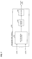
- FIG. 1 is a block diagram of a prior art MIMO receiver 100 for receiving and decoding transmissions from L channel encoders, where L is an integer greater than or equal to two.
- the receiver 100 receives R signals y 1 [m], y 2 [m], . . . , y R [m], corresponding to R receive antennas, where R is an integer greater than or equal to L.
- the R signals y 1 [m], y 2 [m], . . . , y R [m] carry information from S spatial streams, where R ⁇ S ⁇ L.
- a MIMO maximum likelihood (ML) demodulator 104 generally uses the R signals y 1 [m], y 2 [m], . . .
- LLR log likelihood ratio
- an LLR of zero may indicate an equal probability that the bit is a one or a zero.
- the output of the MIMO ML demodulator 104 is S signals, each signal comprising LLR values.
- a spatial stream to layer de-mapper generally maps the S signals from the MIMO ML demodulator 104 corresponding to the S spatial streams to L signals corresponding to the L layers.
- the receiver 100 also includes a deinterleaver 112 and a decoder 116 for each layer.
- the deinterleaver 112 reverses a known bit interleaving process performed at the channel encoder.
- the decoder 116 generally uses the LLR values to decode the signal into a bit stream corresponding to the layer.
- calculating the LLR of a given bit may require a calculation of ⁇ y ⁇ Hx ⁇ 2 for every constellation point in the constellation set in order to determine the smallest distance, where y is a vector corresponding to y 1 [m], y 2 [m], . . . , y R [m], H is an estimate of the MIMO channel, x is a transmit signal vector candidate corresponding to y. Moreover, if there are multiple streams, a calculation of ⁇ y ⁇ Hx ⁇ 2 may be required for every constellation point for every stream.
- the receiver 100 may need to perform M*S calculations of ⁇ y ⁇ Hx ⁇ 2 to demodulate the received S streams.
- FIG. 2 is a block diagram of another prior art MIMO receiver 150 for receiving and decoding transmissions from L channel encoders.
- the MIMO receiver 150 includes L layer receivers 154 and L ⁇ 1 interference cancellers 158 .
- the first layer receiver 154 a processes the R signals y 1 [m], y 2 [m], . . . , y R [m] to demodulate and decode the first layer signal.
- the first layer interference canceller 158 a then re-encodes and re-modulates the output of the receiver 154 a to estimate the components of y 1 [m], y 2 [m], . . . , y R [m] due to the first layer information.
- the interference canceller 158 a subtracts the estimated components due to the first layer from y 1 [m], y 2 [m], . . . , y R [m].
- the interference canceller 158 a attempts to subtract out the interference of the first layer with respect to layers 2 through L.
- the second layer receiver 154 b processes the R signals output from the first interference canceller 158 a to demodulate and decode the second layer signal.
- the second layer interference canceller 158 b then re-encodes and re-modulates the output of the receiver 154 b to estimate the components of y 1 [m], y 2 [m], . . . , y R [m] due to the second layer information.
- the interference canceller 158 b subtracts the estimated components due to the second layer from the output of the first interference canceller 158 a .
- the interference canceller 158 b attempts to subtract out the interference of the second layer with respect to layers 3 through L.
- the L-th layer receiver 154 d processes the R signals output from the (L ⁇ 1)-th interference canceller 158 c to demodulate and decode the L-th layer signal.
- FIG. 3 is a block diagram of a receiver 154 and an interference canceller 158 of FIG. 2 , for an n-th layer.
- the receiver 154 comprises a MIMO linear equalizer 162 that receives R signals y 1 ′[m], y 2 ′[m], . . . , y R ′[m] from an interference canceller for the (n ⁇ 1)-th layer.
- the MIMO linear equalizer 162 outputs S n signals corresponding to the S n spatial streams for the n-th layer.
- a demapper 166 generally demaps the S n signals into a single stream of modulated symbols corresponding to the n-th layer.
- An LLR calculator 170 calculates LLR values corresponding to the modulated symbols.
- a deinterleaver 174 reverses a known bit interleaving process performed at the channel encoder.
- a decoder 178 generally uses the LLR values to decode the signal into a bit stream corresponding to the n-th layer
- the interference canceller 158 includes an encoder 182 , an interleaver 184 , and a modulator 186 that generally attempt to recreate encoding, interleaving and modulation performed by the channel encoder at the transmitter.
- a mapper 188 maps the modulated symbols output by the modulator 186 into the S n spatial streams for the n-th layer.
- a mapper 190 maps the S n spatial streams to T transmit antenna signals. Thus, the mapper 188 and the mapper 190 attempt to recreate mapping functions performed at the transmitter.
- a matrix multiplier 192 multiplies the T signals by a MIMO channel estimate H.
- a subtractor 194 subtracts the output of the matrix multiplier 192 from the signals y 1 ′[m], y 2 ′[m], . . . , y R ′[m].
- a method for decoding a plurality of information streams corresponding to a plurality of layers is disclosed, where the plurality of information streams have been transmitted via a multiple input multiple output (MIMO) communication channel.
- the method includes processing a plurality of received signals to decode information corresponding to a first layer, and generating a plurality of modified received signals using the decoded information corresponding to the first layer and the plurality of received signals.
- the method also includes generating bit metric values for a second layer using MIMO maximum likelihood (ML) demodulation and using the plurality of modified received signals and channel and modulation information for interfering signals.
- the method additionally includes decoding information corresponding to the second layer using the generated bit metric values.
- MIMO multiple input multiple output
- Generating the bit metric values for the second layer may comprise generating bit metric values corresponding to a plurality of spatial streams.
- the method may further include de-mapping the plurality of spatial streams to a single stream of bit metric values prior to decoding, de-interleaving the bit metric values prior to decoding, or pre-processing the plurality of modified received signals for space-time coding.
- the method optionally may include performing a first matrix decomposition on a channel matrix, and preprocessing the plurality of received signals with information from the first matrix decomposition.
- the channel matrix may be preprocessed with information from the first matrix decomposition to generate a first modified channel matrix, wherein the plurality of modified received signals are generated using the first modified channel matrix.
- the method may further include performing a second matrix decomposition on the first modified channel matrix.
- the plurality of modified received signals may be preprocessed with information from the second matrix decomposition, and the first modified channel matrix may be processed with information from the second matrix decomposition to generate a second modified channel matrix, wherein the MIMO ML demodulation uses the second modified channel matrix.
- a successive interference cancellation receiver is disclosed.
- the successive interference cancellation receiver is for receiving a plurality of information streams transmitted via a multiple input multiple output (MIMO) communication channel, the plurality of information streams corresponding to a plurality of layers.
- the successive interference cancellation receiver comprises a first layer receiver to demodulate and decode a plurality of received signals to decode information corresponding to a first layer, and an interference canceller to cancel interference due to the first layer from the plurality of received signals to generate a plurality of modified received signals.
- MIMO multiple input multiple output
- the successive interference cancellation receiver comprises a second layer receiver to demodulate and decode the plurality of modified received signals to decode information corresponding to a second layer, wherein the second receiver includes, and a MIMO maximum likelihood (ML) demodulator to generate bit metric values for the second layer using the plurality of modified received signals and channel and modulation information for interfering signals. Further, the successive interference cancellation receiver comprises a decoder to generate information corresponding to the second layer using the bit metric values.
- ML maximum likelihood
- the successive interference cancellation receiver optionally may include one or more of the following features.
- the second layer receiver may include a pre-processor for space-time coding.
- the second layer receiver may include a MIMO equalizer.
- the second receiver may include a spatial stream de-mapper to de-map the bit metric values.
- the second receiver may include a deinterleaver to deinterleave the bit metric values.
- the first receiver may include a MIMO ML demodulator to generate bit metric values for the first layer using the plurality of received signals and channel and modulation information for interfering signals, and a decoder to generate the information corresponding to the first layer using the bit metric values generated by the MIMO ML demodulator of the first receiver.
- the successive interference cancellation receiver is for receiving a plurality of information streams transmitted via a multiple input multiple output (MIMO) communication channel, the plurality of information streams corresponding to a plurality of layers.
- the successive interference cancellation receiver comprises a plurality of layer receivers, each layer receiver to demodulate and decode a respective plurality of input signals to obtain information corresponding to a respective one of the plurality of layers, and at least one interference canceller, each interference canceller to receive an output from a respective one of the plurality of layer receivers and to cancel interference from the plurality of input signals to the respective one of the plurality of layer receivers, the interference due to a respective one of the plurality of layers.
- MIMO multiple input multiple output
- At least one of the plurality of layer receivers includes a MIMO maximum likelihood (ML) demodulator to generate bit metric values for the respective layer using a plurality of signals generated from one of the interference cancellers and channel and modulation information for interfering signals, and a decoder to generate information corresponding to the respective layer using the bit metric values.
- ML maximum likelihood
- FIG. 1 is a block diagram of a prior art multiple-input, multiple-output (MIMO) maximum likelihood (ML) receiver;
- MIMO multiple-input, multiple-output
- ML maximum likelihood
- FIG. 2 is a block diagram of a prior art successive interference cancellation receiver
- FIG. 3 is a block diagram of a receiver and an interference canceller of the successive interference cancellation receiver of FIG. 2 ;
- FIG. 4 is block diagram of an example model of a MIMO communication system employing multiple channel encoders
- FIG. 5 is a block diagram of an example successive interference cancellation receiver that utilizes MIMO ML techniques
- FIG. 6 is a block diagram of an example pair of a MIMO ML receiver and an interference canceller of the successive interference cancellation receiver of FIG. 5 ;
- FIG. 7 is a block diagram of an example MIMO ML receiver that may be utilized with the successive interference cancellation receiver of FIG. 5 ;
- FIG. 8 a block diagram of another example MIMO ML receiver that may be utilized with the successive interference cancellation receiver of FIG. 5 .
- FIG. 4 is a block diagram of a model 250 of a MIMO transmission system that includes L channel encoders 254 , where L is an integer greater than or equal to two.
- the L channel encoders 254 may be included within a single transmitter, such as within a user device or a base station, or distributed among a plurality of transmitters such as among a plurality of user devices.
- Each channel encoder 254 receives a bit stream corresponding to one of the L layers and encodes the bit stream into a stream of channel symbols such as quadrature amplitude modulation (QAM) symbols, phase shift keying (PSK) symbols, etc.
- QAM quadrature amplitude modulation
- PSK phase shift keying
- Each bit stream may be referred to as a layer, and thus the model 250 includes L layers.
- Each channel encoder 254 may include a bit encoder 258 , an interleaver 262 , and a modulator 266 .
- the bit encoder 258 generally applies an encoding process to the information bits.
- the encoding process may be a forward error correction encoding process, for example.
- the interleaver 262 applies an interleaving process to the output of the bit encoder 258 .
- the interleaving process 262 may help to mitigate burst errors, for example.
- the modulator 266 modulates the bit stream output of the interleaver 262 to generate modulated symbols. Any suitable modulation technique, including known modulating techniques, may be utilized. For example, QAM, M-QAM, PSK, binary PSK (BPSK), amplitude modulation, frequency shift keying (FSK), etc., may be utilized.
- a mapping unit 270 generally maps each output of the channel encoders 254 to one or more spatial streams, to generate a total number of S spatial streams, x 1 [m], x 2 [m], . . . , x s [m], where m is a time index. Alternatively, m may represent a frequency index or any transmission opportunity. In particular, mapping unit 270 maps the output of the n-th channel encoder 254 to S n spatial streams, where
- mapping unit 270 maps modulated symbols to spatial streams.
- the mapping unit 270 may be modeled as matrix multiplication.
- the spatial streams are provided to an effective MIMO channel H ( 274 ).
- the effective channel 274 includes a MIMO precoding block 278 that maps the S spatial streams to T transmit signals ⁇ tilde over (x) ⁇ 1 [m], ⁇ tilde over (x) ⁇ 2 [m], . . . , ⁇ tilde over (x) ⁇ T [m], where T is a number of transmit antennas.
- the MIMO precoding block 278 may be modeled as a matrix P.
- the T transmit signals are transmitted via a MIMO channel ⁇ tilde over (H) ⁇ ( 282 ).
- H represents the effective MIMO communication channel 274
- x represents the spatial streams x 1 [m], x 2 [m], . . . , x s [m]
- z represents the additive noise z 1 [m], z 2 [m], . . . , z R [m] (the time index m has been omitted for notational convenience).
- the model may assume L ⁇ S, S ⁇ T, and S ⁇ R. For super-position coding, however, it may be assumed that L>S.
- Equation 1 can be rewritten as:
- FIG. 5 is a block diagram of an example successive interference cancellation receiver 300 that can be used in a MIMO communication system having multiple channel encoders, such as a system that can be represented by a model such as the model of FIG. 4 .
- the receiver 300 has a structure similar to the receiver of FIG. 2 , and may include the interference cancellers 158 described with reference to FIGS. 2 and 3 . It will be understood, however, that the receiver 300 may utilize an interference canceller different than the interference canceler 158 .
- the MIMO receiver 300 includes L layer receivers 304 and L ⁇ 1 interference cancellers 158 . As will be described in more detail below, each receiver 304 corresponds to a respective one of the L layers. Each receiver is a MIMO maximum likelihood (ML) receiver, and each receiver 304 includes a MIMO ML demodulator.
- the MIMO ML demodulator generally uses the R signals y 1 [m], y 2 [m], . . .
- the MEMO ML demodulator may comprise a soft bit-metric calculator in some embodiments.
- the MIMO ML demodulator may comprise a pre-processing block (e.g., for space-time codes) and/or a MIMO equalizer.
- the first layer receiver 304 a processes the R signals y 1 [m], y 2 [m], . . . , y R [m] to demodulate and decode the first layer signal.
- the first layer interference canceller 158 a then re-encodes and re-modulates the output of the receiver 304 a to estimate the components of y 1 [m], y 2 [m], . . . , y R [m] due to the first layer information.
- the interference canceller 158 a subtracts the estimated components due to the first layer from y 1 [m], y 2 [m], . . . , y R [m].
- the interference canceller 158 a attempts to subtract out the interference of the first layer with respect to layers 2 through L.
- the second layer receiver 304 b processes the R signals output from the first interference canceller 158 a to demodulate and decode the second layer signal.
- the second layer interference canceller 158 b then re-encodes and re-modulates the output of the receiver 304 b to estimate the components of y′ 1 [m], y′ 2 [m], . . . , y′ R [m] due to the second layer information, where y′ 1 [m], y′ 2 [m], . . . , y′ R [m] are the output of the interference canceller 158 a .
- the interference canceller 158 b subtracts the estimated components due to the second layer from the output of the first interference canceller 158 a .
- the interference canceller 158 b attempts to subtract out the interference of the second layer with respect to layers 3 through L. The same technique continues until the L-th layer receiver 304 d processes the R signals output from the (L ⁇ 1)-th interference canceller 158 c to demodulate and decode the L-th layer signal.
- FIG. 6 is a block diagram of an example layer receiver 304 and layer interference canceller 158 pair for an n-th layer.
- the receiver 304 includes a MIMO ML demodulator 308 .
- the MIMO ML demodulator 308 receives the R input signals and generates LLR values for each of the S n spatial streams corresponding to the n-th layer.
- a de-mapper unit 312 receives the S n output signals from the MIMO ML demodulator 308 and generates a single signal corresponding to the n-th layer. Generally, the de-mapper unit 312 undoes a known mapping function that maps a layer signal to S n spatial streams performed at a transmitter. The output of the de-mapper unit 312 is a stream of LLR values.
- the receiver 304 also includes a deinterleaver 316 and a decoder 320 .
- the deinterleaver 316 reverses a known bit interleaving process performed at the channel encoder for the n-th layer.
- the decoder 320 generally uses the LLR values to decode the signal into a bit stream corresponding to the n-th layer.
- the R signals received by the n-th receiver 304 can be expressed as:
- y n the set of signals received by the receiver 304 corresponding to the n-th layer
- ⁇ circumflex over (x) ⁇ i the estimate of the spatial streams corresponding to the i-th layer generated by the interference canceller 158 corresponding to the i-th layer.
- Equation 3 Equation 3
- Equation 4 can be rewritten as:
- the signals from layers 1 to n ⁇ 1 may be assumed to be removed and the signals from layers n+1 to L may be considered as interference.
- MIMO ML demodulation in the presence of interference can be utilized in one or more of the receivers 304 .
- a receiver such as the example receiver 350 of FIG. 7 may be utilized as the receiver 304 of FIG. 6 .
- the receiver 304 of FIG. 6 may be configured to operate as the receiver 350 , for example.
- the receiver 350 includes a soft bit metric calculator 354 , the de-interleaver 316 , and hard-decision decoder 320 .
- Each of these components may correspond to a channel encoder component at a transmitter and may effectively undo the operation performed by the corresponding transmitter component.
- soft bit metric calculator 354 may correspond to modulator 266 that can demodulate/de-map receive signals according to the same modulation scheme as that used by the modulator 266 .
- De-interleaver 316 may correspond to interleaver 262 and may return the symbol order of the received data into its original order, e.g., the order expected by the decoder 320 .
- the decoder 320 may be a soft-decoder that corresponds to encoder 220 , and may perform decoding based on the same error correcting code (e.g., convolutional code) as encoder 258 . Thus, the decoder 320 may produce an estimate of the information bits for the n-th layer.
- error correcting code e.g., convolutional code
- the soft bit metric calculator 354 may calculate soft information for each bit of information contained within the intended signal.
- the soft information may be in the form of a log-likelihood ratio (LLR) for each received bit of intended information.
- LLR log-likelihood ratio
- the soft information can be proportional to an LLR.
- the soft bit metric calculator 354 may, for example, calculate an LLR according to:
- b i is the transmitted bit of the intended information contained within y k for which the LLR is being calculated.
- the soft bit metric calculator 354 can obtain a reliable log-likelihood ratio based on Equation 6 by using accurate estimates of the channel information for the intended channel and any interference channels, as well as modulation information for these channels.
- the receiver 300 may, for example, include computational logic (not shown) that is configured to estimate the interference channel gain for each receive antenna and each interfering source.
- the computational logic may also be configured to compute the intended channel gain for each receive antenna.
- the computational logic can compute these channel information estimates by analyzing the characteristics of pilot patterns received from one or more transmitters, for example. From the analysis of various pilot patterns, the computational logic can produce an estimate of the interference and/or intended channel gain, for example.
- the receiver 300 may compute the channel information estimates at any suitable time during operation, such as at power-up, when initially connected to a transmitter, periodically, whenever the pilot sequence is transmitted, etc.
- the receiver 300 may also include a control information decoder (not shown) to compute the modulation information for an intended source and any interference sources.
- the receiver 300 may include a downlink map (DL-MAP) decoder that decodes a DL-MAP message received from each base station. From the DL-MAP message, the receiver 300 can retrieve the modulation information. Since a DL-MAP message or other control message may be heavily encoded and may be transmitted using frequency reuse, the receiver may be able to accurately decode the control information from the interfering source even if noise and/or interference prevents receiver 300 from accurately decoding regular data from the interfering source.
- DL-MAP downlink map
- the soft bit metric calculator 354 may compute the expected receive signal vector based on substantially all of the signals that can affect the receive signal vector. For example, referring briefly again to FIG. 4 , if an interfering source operates with a 4-QAM scheme, the soft bit metric calculator 354 can compute bit metric information with the knowledge that the interference from this interfering source takes on only four possible values (e.g., magnitude of one with four different phases).
- the soft bit metric calculator 354 may assume that the noise, z, can be modeled as additive noise (e.g., white Gaussian noise), and can be configured to compute the log-likelihood ratio for bit b i of the intended information according to:
- additive noise e.g., white Gaussian noise
- Equation 7 X i (j) is the set of symbols that have a bit value of j at bit position b i and ⁇ z 2 is the power of the noise.
- This expression is a function of the channel information for each interfering layer and a transmit signal for each interfering layer. Therefore, the expression uses both the channel information estimate (to obtain each h k,j ) and the modulation information.
- Equation 7 Equation 7, and any of the other LLR equations provided below are merely illustrative, and that other LLR equations may be computed by the soft bit metric calculator 354 .
- the soft bit metric calculator 354 can operate using a different equation that is based on a distance between a receive signal vector and one or more expected receive signal vectors. This distance calculation may sometimes be referred to as a “distance metric.”
- the soft bit metric calculator 354 can operate using any suitable distance metric, including but not limited to the distance metric of Equation 7.
- an approximation can be implemented to simplify the complexity of the hardware (e.g., logic) or software.
- a conventional implementation of the soft bit metric calculator 354 may employ an approximation for computing logarithms, and can instead calculate,
- U* k is the inverse of a unitary matrix, U k . Because the multiplication is performed using a unitary matrix, this multiplication does not affect the magnitude of each component, and therefore also does not affect the squared Euclidean distance.
- the unitary matrix may be Q k , which is the unitary matrix that results from the QR decomposition of the channel matrix.
- the critical path in the computation of the Euclidean distance metric is the multiplication of a matrix by the transmit signal vector, since this multiplication can occur for up to every possible value of the transmit signal vector.
- the computational complexity of the Euclidean distance metric may be decreased substantially. It should be understood that the use of Q k as the unitary matrix is merely illustrative, and other suitable unitary matrices may be selected instead.
- QR factorization can be applied at the beginning of each layer.
- the received signal and the channel matrix for layer 1 can be preprocessed by the Q matrix of the channel matrix.
- the modified received signal is generated by multiplying Q* with the received signal
- the modified channel matrix is generated by multiplying Q* with the channel matrix, which is equivalent to the R matrix.
- this modified received signal and the modified channel matrix may be used by the receiver for layer 1 block 304 a and interference cancellation for layer 1 block 158 a in FIG. 5 .
- the output of the interference cancellation for layer 1 block 158 a can be similarly preprocessed before it is supplied to the receiver for layer 2 block 304 b and the interference cancellation for layer 2 block 158 b .
- a new channel matrix at layer 2 is first formed by removing the columns corresponding to layer 1 from the modified channel matrix at layer 1 . Then, QR factorization can be applied to this new channel matrix at layer 1 , and the resulting Q matrix can be used to preprocess the signals before they are applied to the next layer. Similarly, at each stage, QR factorization can be performed, and the interference-cancelled received signal and the channel matrix can be preprocessed. By doing this QR-based preprocessing, the dimension of the received signal and the channel matrix can be reduced further and further at each layer, resulting in increasingly lower computational complexity at each layer.
- the strength of interfering signals may be strong compared to that of the intended signal on only a subset of the receive antennas. That is, the signal-to-interference plus noise ratio (SINR) may be different for different receive antennas such that some of the antennas are strongly affected by interfering signals while others are not.
- SINR signal-to-interference plus noise ratio
- a receiver can be configured to compute soft information using only those receive antennas having a SINR with at least a predetermined value (e.g., 2 dB, 5 dB, etc.). For example, if a receiver has three receive antennas and only one antenna has an associated SINR that is high, it may be possible to accurately estimate the intended information using only the signal received on the one antenna.
- the signals receive on the other two receive antennas with low SINR may be ignored, thereby decreasing the amount and/or complexity of the computations necessary to obtain soft information for the intended information. More particularly, the receiver 350 may compute Equation 7 or Equation 8 to obtain soft information, but can compute these equations using fewer than the R components of the receive and channel vectors. As described in greater detail below, a receiver 350 may adaptively determine a subset of the receive dimensions (e.g., receive antennas) to use when decoding a receive signal vector.
- an interfering source may not have a strong effect compared to the intended source and/or other interfering sources. Therefore, the interfering signals with reduced effect may be ignored in calculating the log-likelihood equations of Equation 7 and/or Equation 8.
- the receiver 350 may compute fewer total Euclidean distance metrics, because of the decrease in number of total possible transmit signal vectors. Also, the number of computations in each Euclidean distance metric may be decreased, since J is decreased. Therefore, by adaptively decreasing the number of interfering signals, the complexity of computing soft information can be reduced.
- these interference signals may instead be modeled as background noise.
- the receiver 350 can model the interference signal as additive noise, such as white Gaussian noise, and can compute Equation 7 and/or Equation 8 by including the power of the interfering signal with ⁇ z 2 , the power of the background noise. This way, the complexity of computing soft information can be decreased without completely ignoring the presence of an interfering source.
- the receiver 304 alternatively can be implemented using other suitable techniques as well.
- the n-th layer has more one or more spatial streams
- techniques disclosed in U.S. patent application Ser. No. 12/207,350, entitled “MIMO Decoding in the Presence of Various Interfering Sources,” filed on Sep. 9, 2008, which is hereby incorporated by reference herein in its entirety, may be used.
- FIG. 8 is a block diagram of an example receiver 400 that may be used as the receiver 304 in FIGS. 5 and 6 .
- the receiver 400 may obtain information regarding the one or more interfering signals (i.e., including the interfering signals from layers n+1 to L) in a wired or wireless manner.
- the interfering signals include signals sent from a different transmitter than the transmitter sending the layer n signals
- the receiver 400 or the communication device in which the receiver 400 is included
- the receiver 400 may receive from the other transmitter(s) such information as modulation schemes, MIMO mode, etc. and, based on the received information.
- the receiver 400 may be included in a base station communicatively coupled to other base stations via a wired network backbone (not shown).
- the multiple base stations may each support multiple mobile stations communicating, for example, according to an OFDMA scheme configured optionally to use the same frequency band.
- the base stations may exchange such information as modulation schemes, MIMO mode, etc. and, based on the received information, estimate a set of parameters to generate a channel model.
- the mobile stations operating in the cells supported by the other base stations may be significant sources of interference for the receiver 400 during receiving and decoding of the intended streams from one or more mobile stations operating in the cell corresponding to the receiver 400 .
- the signals from the other base stations may create additional interference for the receiver 400 .
- the receiver 400 may estimate channel information due to the interfering signals by processing unique PN sequences corresponding to the interfering signals and known to the receiver 400 .
- the PN sequences may correspond to neighboring base stations or mobile devices communication with the neighbor base stations, and could be received from the neighbor base stations.
- the receiver 400 when the receiver 400 is included in a base station, the receiver 400 , or another device coupled to the receiver 400 , may estimate the uplink channel as a set of both the intended streams and the interfering streams based on the information received via a wired backbone, a wireless network, etc.
- the receiver 400 when the receiver 400 is included in a mobile station, the receiver 400 , or another device coupled to the receiver 400 , may estimate the downlink channel, including both the parameters related to the intended streams and to the interfering streams, based on wireless signals only.
- a mobile station operating in a WiMAX network may estimate the portion of the channel related to the interfering sources from a Downlink Map (DL-MAP) message broadcast by the adjacent base stations using the same carrier frequency as the frequency on which the mobile station receives the one or more intended streams.
- DL-MAP Downlink Map
- the DL-MAP message specifies the allocation of resources (i.e., carrier frequencies, timeslots, etc.) in the OFDMA scheme.
- the mobile station can obtain a set of parameters that may be used for constructing the channel model discussed below. Further, a mobile station may obtain these or additional channel parameters from the periodic broadcasts of PN sequences, similarly to processing of PN sequences at a base station discussed above.
- the receiver 400 may decode the received signals in accordance with the model discussed above.
- the receiver 400 may pre-process the input signals using a pre-processor 404 , such as a pre-processor for space-time code, optionally equalize the received signals in a MIMO equalizer 408 , and demodulate the received signals in a demodulator 412 .
- a pre-processor 404 such as a pre-processor for space-time code
- optionally equalize the received signals in a MIMO equalizer 408 optionally equalize the received signals in a MIMO equalizer 408 , and demodulate the received signals in a demodulator 412 .
- the pre-processor 404 may be omitted, or the receiver 400 may bypass the pre-processor 404 .
- the MIMO equalization module 408 may implement any suitable MIMO equalization techniques, including those currently known in the art.
- the MIMO equalization module 408 may operate as a zero-forcing (ZF) linear equalizer (LE), a minimum mean square error liner equalizer (MMSE LE), a ZF decision feedback equalizer (DFE), an MMSE DFE, etc.
- ZF zero-forcing
- L minimum mean square error liner equalizer
- DFE ZF decision feedback equalizer
- the input to the receiver 400 can be expressed as:
- the demodulator 412 may next estimate each received symbol by using the log-likelihood ratio (LLR) approach.
- LLR log-likelihood ratio
- the demodulator 412 may calculate the LLR value for the i-th symbol in the first intended stream x 1 by applying the formula
- LLR 1 , I log ⁇ ( ⁇ x ⁇ X 1 , I ( 1 ) ⁇ exp ⁇ ( ⁇ y ⁇ 1 - h ⁇ row , 1 ⁇ x ⁇ 2 ⁇ z ⁇ 1 2 ) ) - log ⁇ ( ⁇ x ⁇ X 1 , I ( 0 ) ⁇ exp ⁇ ( ⁇ y ⁇ 1 - h ⁇ row , 1 ⁇ x ⁇ 2 ⁇ z ⁇ 1 2 ) ) , ( Equation ⁇ ⁇ 16 ) where ⁇ tilde over (h) ⁇ row,r is r-th row of ⁇ tilde over (H) ⁇ and X s,I (b) is a set of vectors of signal constellation points whose value in the I-th symbol position of the s-th element is equal to b, and where ⁇ is variance of the noise.
- the receiver 400 may directly proceed to calculating LLR values in the demodulator 412 without performing MIMO equalization in the module 408 if the incoming data is non-space-time encoded.
- LLR s , I log ⁇ ( ⁇ x ⁇ X s , I ( 1 ) ⁇ exp ⁇ ( ⁇ ⁇ y - Hx ⁇ ⁇ 2 ⁇ z 2 ) ) - log ⁇ ( ⁇ x ⁇ X s , I ( 0 ) ⁇ exp ⁇ ( ⁇ ⁇ y - Hx ⁇ ⁇ 2 ⁇ z 2 ) ) . ( Equation ⁇ ⁇ 17 )
- the demodulator 412 or another component of the receiver 400 may also simplify the computation based on max-log-map approximation.
- the receiver 400 may reduce the complexity of equalization-free LLR computation by decomposing the matrix H into an orthogonal and a triangular matrix (e.g., by performing the known technique of QR decomposition). If a certain embodiment of the receiver 400 relies on QR decomposition, the demodulator 412 may work with Q*y and R rather than with y and H, where * denotes a complex conjugate.
- linear filtering on the received signal or the modified received signal may be performed to reduce the dimension of the received signal (or modified received signal) to less than R, but equal to or larger than S. Then, techniques such as described above can be performed on the reduced dimension signals, i.e., as if the number of antennas is reduced.
- all of the channel encoders 254 may be included in a single transmitter (e.g., a base station), or the channel encoders 254 may be distributed amongst multiple transmitters (e.g., as in the uplink of a cellular system). In either situation, a single successive interference cancellation receiver such as in FIG. 5 may be utilized to decode all L layers.
- each receiver may be similar to the successive interference cancellation receiver of FIG. 5 , but omit processing for at least some layers that are not intended for the receiver.
- the order in which the layers are processed by the successive interference cancellation receiver may be ordered to improve performance, for example, and any suitable ordering scheme may be utilized.
- the ordering may be based on the SINR of the signals of the different layers.
- the first layer may be selected as the layer having the best SINR
- the second layer may be selected as the layer having the second best SINR, etc.
- the first layer may be selected as the layer having the best SINR.
- SINR for the remaining layers may be recalculated after interference due to the first layer has been subtracted out.
- the second layer may be selected as the layer having the best recalculated SINR, and so on.
- the various blocks, operations, and techniques described above may be implemented in hardware, firmware, software, or any combination of hardware, firmware, and/or software.
- the software or firmware may be stored in any computer readable memory such as on a magnetic disk, an optical disk, or other storage medium, in a RAM or ROM or flash memory, processor, hard disk drive, optical disk drive, tape drive, etc.
- the software or firmware may be delivered to a user or a system via any known or desired delivery method including, for example, on a computer readable disk or other transportable computer storage mechanism or via communication media.
- Communication media typically embodies computer readable instructions, data structures, program modules or other data in a modulated data signal such as a carrier wave or other transport mechanism.
- modulated data signal means a signal that has one or more of its characteristics set or changed in such a manner as to encode information in the signal.
- communication media includes wired media such as a wired network or direct-wired connection, and wireless media such as acoustic, radio frequency, infrared and other wireless media.
- the software or firmware may be delivered to a user or a system via a communication channel such as a telephone line, a DSL line, a cable television line, a fiber optics line, a wireless communication channel, the Internet, etc. (which are viewed as being the same as or interchangeable with providing such software via a transportable storage medium).
- the software or firmware may include machine readable instructions that are capable of causing one or more processors to perform various acts.
Abstract
Description
In other words, the
y=Hx+z, (Equation 1)
where
in which y represents, in vector form, the received signals y1[m], y2[m], . . . , yR[m], H represents the effective
in which x1 represents the spatial streams corresponding to the i-th layer, Si is the number of spatial streams corresponding to the i-th layer, and Hi is a matrix representing the effective MIMO communication channel for the spatial streams corresponding to the i-th layer.
where yn is the set of signals received by the
Equation 4 can be rewritten as:
Thus, for the LLR calculations of bits corresponding to the spatial streams in layer n, the signals from
where bi is the transmitted bit of the intended information contained within yk for which the LLR is being calculated. The soft bit
in both logarithm computations produces an accurate estimate of the expected receive signal vector for each possible transmit vector. This expression is a function of the channel information for each interfering layer and a transmit signal for each interfering layer. Therefore, the expression uses both the channel information estimate (to obtain each hk,j) and the modulation information.
DM=∥ k −H k x k∥2 (Equation 9)
in Equation 7 and/or Equation 8, the squared distance computation may be altered in a way that does not change the result of the computation. For example, the soft bit
DM=∥U* k y k −U* k H k x k∥2 (Equation 10)
in place of the squared Euclidean distances shown in Equations 7 and 8. Here, U*k is the inverse of a unitary matrix, Uk. Because the multiplication is performed using a unitary matrix, this multiplication does not affect the magnitude of each component, and therefore also does not affect the squared Euclidean distance.
H k =Q k R k (Equation 11)
where Qk is an R×J unitary matrix and Rk is a J×J upper triangular matrix, where J is equal to
for the n-th layer receiver or L−
DM=∥Q* k y k −R k x k∥2 (Equation 12)
for the different possible transmit signal vectors. The critical path in the computation of the Euclidean distance metric is the multiplication of a matrix by the transmit signal vector, since this multiplication can occur for up to every possible value of the transmit signal vector. Therefore, by altering the Euclidean distance metric such that the transmit signal vector is multiplied by an upper triangular matrix instead of a full matrix, the computational complexity of the Euclidean distance metric may be decreased substantially. It should be understood that the use of Qk as the unitary matrix is merely illustrative, and other suitable unitary matrices may be selected instead.
the
{tilde over (y)}={tilde over (H)}x+{tilde over (z)} (Equation 14)
It is apparent that the equalized channel matrix {tilde over (H)} forces x2 and x1 to zero when calculating {tilde over (y)}1 and {tilde over (y)}2, respectively, thereby canceling the mutual impact of the intended streams.
where {tilde over (h)}row,r is r-th row of {tilde over (H)} and Xs,I (b) is a set of vectors of signal constellation points whose value in the I-th symbol position of the s-th element is equal to b, and where σ is variance of the noise.
Claims (21)
Priority Applications (3)
| Application Number | Priority Date | Filing Date | Title |
|---|---|---|---|
| US12/543,363 US8411806B1 (en) | 2008-09-03 | 2009-08-18 | Method and apparatus for receiving signals in a MIMO system with multiple channel encoders |
| US13/854,774 US8711989B1 (en) | 2008-09-03 | 2013-04-01 | Method and apparatus for receiving signals in a MIMO system with multiple channel encoders |
| US14/258,326 US9071295B1 (en) | 2008-09-03 | 2014-04-22 | Method and apparatus for receiving signals in a MIMO system with multiple channel encoders |
Applications Claiming Priority (2)
| Application Number | Priority Date | Filing Date | Title |
|---|---|---|---|
| US9386308P | 2008-09-03 | 2008-09-03 | |
| US12/543,363 US8411806B1 (en) | 2008-09-03 | 2009-08-18 | Method and apparatus for receiving signals in a MIMO system with multiple channel encoders |
Related Child Applications (1)
| Application Number | Title | Priority Date | Filing Date |
|---|---|---|---|
| US13/854,774 Continuation US8711989B1 (en) | 2008-09-03 | 2013-04-01 | Method and apparatus for receiving signals in a MIMO system with multiple channel encoders |
Publications (1)
| Publication Number | Publication Date |
|---|---|
| US8411806B1 true US8411806B1 (en) | 2013-04-02 |
Family
ID=47989849
Family Applications (3)
| Application Number | Title | Priority Date | Filing Date |
|---|---|---|---|
| US12/543,363 Active 2031-06-29 US8411806B1 (en) | 2008-09-03 | 2009-08-18 | Method and apparatus for receiving signals in a MIMO system with multiple channel encoders |
| US13/854,774 Active US8711989B1 (en) | 2008-09-03 | 2013-04-01 | Method and apparatus for receiving signals in a MIMO system with multiple channel encoders |
| US14/258,326 Active US9071295B1 (en) | 2008-09-03 | 2014-04-22 | Method and apparatus for receiving signals in a MIMO system with multiple channel encoders |
Family Applications After (2)
| Application Number | Title | Priority Date | Filing Date |
|---|---|---|---|
| US13/854,774 Active US8711989B1 (en) | 2008-09-03 | 2013-04-01 | Method and apparatus for receiving signals in a MIMO system with multiple channel encoders |
| US14/258,326 Active US9071295B1 (en) | 2008-09-03 | 2014-04-22 | Method and apparatus for receiving signals in a MIMO system with multiple channel encoders |
Country Status (1)
| Country | Link |
|---|---|
| US (3) | US8411806B1 (en) |
Cited By (25)
| Publication number | Priority date | Publication date | Assignee | Title |
|---|---|---|---|---|
| US20130329830A1 (en) * | 2011-02-25 | 2013-12-12 | Osaka University | Receiving device, transmitting device, receiving method, transmitting method, program, and wireless communication system |
| US8711989B1 (en) * | 2008-09-03 | 2014-04-29 | Marvell International Ltd. | Method and apparatus for receiving signals in a MIMO system with multiple channel encoders |
| CN104022808A (en) * | 2013-09-19 | 2014-09-03 | 华为技术有限公司 | Method and user equipment in wireless communication network |
| US20150215071A1 (en) * | 2012-08-09 | 2015-07-30 | Telefonaktiebolaget L M Ericsson (Publ) | Method and a node for detecting phase noise in mimo communication systems |
| US9118446B2 (en) | 2013-09-19 | 2015-08-25 | Huawei Technologies Co., Ltd. | Methods and user equipment in a wireless communication network |
| US9154983B2 (en) | 2013-01-14 | 2015-10-06 | Qualcomm Incorporated | Systems and methods for detecting or signaling the presence of bursty interference on wireless networks |
| US9197461B1 (en) | 2013-03-12 | 2015-11-24 | Marvell International Ltd. | Method and apparatus for memory efficient architecture of successive interference cancellation for MIMO systems |
| CN105323202A (en) * | 2014-07-31 | 2016-02-10 | 三星电子株式会社 | Interference cancellation method of user equipment in cellular communication system |
| US9312895B1 (en) | 2008-08-07 | 2016-04-12 | Hypres, Inc. | Two stage radio frequency interference cancellation system and method |
| US20160241316A1 (en) * | 2015-02-13 | 2016-08-18 | Wi-Lan Labs, Inc. | Enhanced pre-ordered pre-weighted transmission |
| CN106161294A (en) * | 2015-04-22 | 2016-11-23 | 深圳市中兴微电子技术有限公司 | A kind of data processing method and device |
| US20170047071A1 (en) * | 2014-04-25 | 2017-02-16 | Dolby Laboratories Licensing Corporation | Audio Segmentation Based on Spatial Metadata |
| US20170099165A1 (en) * | 2015-10-06 | 2017-04-06 | Huawei Technologies Co., Ltd. | System and Method for State Reduction in Trellis Equalizers Using Bounded State Enumeration |
| US9722730B1 (en) | 2015-02-12 | 2017-08-01 | Marvell International Ltd. | Multi-stream demodulation schemes with progressive optimization |
| US20180034521A1 (en) * | 2015-02-10 | 2018-02-01 | Nippon Hoso Kyokai | Transmitter, receiver, and semiconductor chip |
| US20180041306A1 (en) * | 2016-08-03 | 2018-02-08 | Samsung Electronics Co., Ltd. | System and method for providing interference parameter estimation for multi-input multi-output (mimo) communication system |
| US9942020B1 (en) * | 2017-04-26 | 2018-04-10 | Cisco Technology, Inc. | Minimum delay spatio-temporal filtering for interference rejection |
| US9979567B2 (en) * | 2016-03-30 | 2018-05-22 | Mstar Semiconductor, Inc. | Equalization enhancing module, demodulation system and equalization enhancing method |
| TWI634755B (en) * | 2017-02-10 | 2018-09-01 | 瑞昱半導體股份有限公司 | Demodulation method and receiving device |
| US10797930B1 (en) * | 2019-01-30 | 2020-10-06 | Nokia Technologies Oy | Apparatus and method for detection of received signals |
| US20210091984A1 (en) * | 2018-05-31 | 2021-03-25 | Indian Institute Of Technology Hyderabad | Method of receiving signal stream and a receiver |
| US11539557B1 (en) * | 2021-12-16 | 2022-12-27 | Qualcomm Incorporated | Multi-level coding for power efficient channel coding |
| US11777585B2 (en) * | 2021-09-03 | 2023-10-03 | Nec Corporation | Wireless receiving apparatus and method thereof |
| US11799700B1 (en) * | 2022-08-31 | 2023-10-24 | Qualcomm Incorporated | Decoding multi-level coded (MLC) systems |
| US20230396472A1 (en) * | 2022-06-03 | 2023-12-07 | Renesas Electronics America Inc. | Digital Demodulation for Wireless Power |
Families Citing this family (6)
| Publication number | Priority date | Publication date | Assignee | Title |
|---|---|---|---|---|
| GB2511370B (en) * | 2013-08-29 | 2015-07-08 | Imagination Tech Ltd | Low complexity soft output MIMO decoder |
| CA3065394C (en) * | 2015-03-06 | 2022-05-17 | Electronics And Telecommunications Research Institute | Broadcast signal frame generating apparatus and broadcast signal frame generating method using bootstrap and preamble |
| US11026055B1 (en) | 2020-08-03 | 2021-06-01 | Pivotal Commware, Inc. | Wireless communication network management for user devices based on real time mapping |
| EP4278645A1 (en) | 2021-01-15 | 2023-11-22 | Pivotal Commware, Inc. | Installation of repeaters for a millimeter wave communications network |
| CA3224854A1 (en) * | 2021-07-07 | 2023-01-12 | Pivotal Commware, Inc. | Multipath repeater systems |
| WO2023205182A1 (en) | 2022-04-18 | 2023-10-26 | Pivotal Commware, Inc. | Time-division-duplex repeaters with global navigation satellite system timing recovery |
Citations (17)
| Publication number | Priority date | Publication date | Assignee | Title |
|---|---|---|---|---|
| US20020150187A1 (en) | 2000-12-04 | 2002-10-17 | Trellis Ware Technologies, Inc. | Method for co-channel interference identication and mitigation |
| US20050025039A1 (en) | 2003-07-30 | 2005-02-03 | Samsung Electronics Co., Ltd. | Apparatus and method for assigning subchannel in a mobile communication system using orthogonal frequency division multiple access scheme |
| US20050053172A1 (en) * | 2003-09-10 | 2005-03-10 | Nokia Corporation | Method and apparatus providing an advanced MIMO receiver that includes a signal-plus-residual-interference (SPRI) detector |
| US20050101259A1 (en) | 2003-11-06 | 2005-05-12 | Wen Tong | Communication channel optimization systems and methods in multi-user communication systems |
| US20050201478A1 (en) * | 2004-03-10 | 2005-09-15 | Holger Claussen | Modulation in a mobile telecommunications system |
| US20050286462A1 (en) | 2004-06-25 | 2005-12-29 | Samsung Electronics Co., Ltd. | OFDM symbol transmission method and apparatus for providing sector diversity in a mobile communication system, and system using the same |
| WO2006056836A1 (en) | 2004-11-24 | 2006-06-01 | Nokia Corporation | Fft accelerated iterative mimo equalizer receiver architecture |
| US20060198460A1 (en) * | 2005-03-03 | 2006-09-07 | Texas Instruments Incorporated | Link adaptation for high throughput multiple antenna WLAN systems |
| US20060269023A1 (en) | 2005-05-26 | 2006-11-30 | Intel Corporation | Interference rejection in wireless networks |
| US20070135125A1 (en) | 2005-12-10 | 2007-06-14 | Samsung Electronics Co., Ltd. | Apparatus and method for hard handover in a wireless communication system |
| US20070165737A1 (en) | 2006-01-17 | 2007-07-19 | Marvell International Ltd. | Order recursive computation for a MIMO equalizer |
| US20070183541A1 (en) * | 2005-07-28 | 2007-08-09 | Broadcom Corporation | Modulation-type discrimination in a wireless communication network |
| US20070211813A1 (en) | 2006-03-10 | 2007-09-13 | Shilpa Talwar | MIMO precoding in the presence of co-channel interference |
| US20070230608A1 (en) | 2006-03-31 | 2007-10-04 | Guangjie Li | Method and apparatus for quasi maximum likelihood MIMO detection |
| US20080025442A1 (en) | 2006-03-09 | 2008-01-31 | Samsung Electronics Co., Ltd. | Method and apparatus for receiving data in a communication system |
| US20080239938A1 (en) | 2006-03-30 | 2008-10-02 | Beceem Communications Inc. | Method and system for uplink coordinated reception in orthogonal frequency division multiple access systems |
| US8135098B2 (en) | 2007-05-11 | 2012-03-13 | Marvell World Trade Ltd. | BICM decoding in the presence of co-channel interference |
Family Cites Families (3)
| Publication number | Priority date | Publication date | Assignee | Title |
|---|---|---|---|---|
| US8243860B1 (en) | 2007-07-18 | 2012-08-14 | Marvell International Ltd. | Co-channel interference cancellation with multiple receive antennas for BICM |
| US8155233B1 (en) | 2007-09-11 | 2012-04-10 | Marvell International Ltd. | MIMO decoding in the presence of various interfering sources |
| US8411806B1 (en) * | 2008-09-03 | 2013-04-02 | Marvell International Ltd. | Method and apparatus for receiving signals in a MIMO system with multiple channel encoders |
-
2009
- 2009-08-18 US US12/543,363 patent/US8411806B1/en active Active
-
2013
- 2013-04-01 US US13/854,774 patent/US8711989B1/en active Active
-
2014
- 2014-04-22 US US14/258,326 patent/US9071295B1/en active Active
Patent Citations (17)
| Publication number | Priority date | Publication date | Assignee | Title |
|---|---|---|---|---|
| US20020150187A1 (en) | 2000-12-04 | 2002-10-17 | Trellis Ware Technologies, Inc. | Method for co-channel interference identication and mitigation |
| US20050025039A1 (en) | 2003-07-30 | 2005-02-03 | Samsung Electronics Co., Ltd. | Apparatus and method for assigning subchannel in a mobile communication system using orthogonal frequency division multiple access scheme |
| US20050053172A1 (en) * | 2003-09-10 | 2005-03-10 | Nokia Corporation | Method and apparatus providing an advanced MIMO receiver that includes a signal-plus-residual-interference (SPRI) detector |
| US20050101259A1 (en) | 2003-11-06 | 2005-05-12 | Wen Tong | Communication channel optimization systems and methods in multi-user communication systems |
| US20050201478A1 (en) * | 2004-03-10 | 2005-09-15 | Holger Claussen | Modulation in a mobile telecommunications system |
| US20050286462A1 (en) | 2004-06-25 | 2005-12-29 | Samsung Electronics Co., Ltd. | OFDM symbol transmission method and apparatus for providing sector diversity in a mobile communication system, and system using the same |
| WO2006056836A1 (en) | 2004-11-24 | 2006-06-01 | Nokia Corporation | Fft accelerated iterative mimo equalizer receiver architecture |
| US20060198460A1 (en) * | 2005-03-03 | 2006-09-07 | Texas Instruments Incorporated | Link adaptation for high throughput multiple antenna WLAN systems |
| US20060269023A1 (en) | 2005-05-26 | 2006-11-30 | Intel Corporation | Interference rejection in wireless networks |
| US20070183541A1 (en) * | 2005-07-28 | 2007-08-09 | Broadcom Corporation | Modulation-type discrimination in a wireless communication network |
| US20070135125A1 (en) | 2005-12-10 | 2007-06-14 | Samsung Electronics Co., Ltd. | Apparatus and method for hard handover in a wireless communication system |
| US20070165737A1 (en) | 2006-01-17 | 2007-07-19 | Marvell International Ltd. | Order recursive computation for a MIMO equalizer |
| US20080025442A1 (en) | 2006-03-09 | 2008-01-31 | Samsung Electronics Co., Ltd. | Method and apparatus for receiving data in a communication system |
| US20070211813A1 (en) | 2006-03-10 | 2007-09-13 | Shilpa Talwar | MIMO precoding in the presence of co-channel interference |
| US20080239938A1 (en) | 2006-03-30 | 2008-10-02 | Beceem Communications Inc. | Method and system for uplink coordinated reception in orthogonal frequency division multiple access systems |
| US20070230608A1 (en) | 2006-03-31 | 2007-10-04 | Guangjie Li | Method and apparatus for quasi maximum likelihood MIMO detection |
| US8135098B2 (en) | 2007-05-11 | 2012-03-13 | Marvell World Trade Ltd. | BICM decoding in the presence of co-channel interference |
Non-Patent Citations (15)
Cited By (39)
| Publication number | Priority date | Publication date | Assignee | Title |
|---|---|---|---|---|
| US9312895B1 (en) | 2008-08-07 | 2016-04-12 | Hypres, Inc. | Two stage radio frequency interference cancellation system and method |
| US9838051B1 (en) | 2008-08-07 | 2017-12-05 | Hypres, Inc. | Two stage radio frequency interference cancellation system and method |
| US8711989B1 (en) * | 2008-09-03 | 2014-04-29 | Marvell International Ltd. | Method and apparatus for receiving signals in a MIMO system with multiple channel encoders |
| US9071295B1 (en) * | 2008-09-03 | 2015-06-30 | Marvell International Ltd. | Method and apparatus for receiving signals in a MIMO system with multiple channel encoders |
| US20130329830A1 (en) * | 2011-02-25 | 2013-12-12 | Osaka University | Receiving device, transmitting device, receiving method, transmitting method, program, and wireless communication system |
| US9191080B2 (en) * | 2011-02-25 | 2015-11-17 | Sharp Kabushiki Kaisha | Reception device, transmission device, reception method, transmission method, program, and radio communication system |
| US9461773B2 (en) * | 2012-08-09 | 2016-10-04 | Stefano Chinnici | Method and a node for detecting phase noise in MIMO communication systems |
| US20150215071A1 (en) * | 2012-08-09 | 2015-07-30 | Telefonaktiebolaget L M Ericsson (Publ) | Method and a node for detecting phase noise in mimo communication systems |
| US9154983B2 (en) | 2013-01-14 | 2015-10-06 | Qualcomm Incorporated | Systems and methods for detecting or signaling the presence of bursty interference on wireless networks |
| US9197461B1 (en) | 2013-03-12 | 2015-11-24 | Marvell International Ltd. | Method and apparatus for memory efficient architecture of successive interference cancellation for MIMO systems |
| EP2852080A1 (en) * | 2013-09-19 | 2015-03-25 | Huawei Technologies Co., Ltd. | Methods and user equipment in a wireless communication network |
| CN104022808B (en) * | 2013-09-19 | 2017-10-17 | 华为技术有限公司 | Method and user equipment in cordless communication network |
| US9118446B2 (en) | 2013-09-19 | 2015-08-25 | Huawei Technologies Co., Ltd. | Methods and user equipment in a wireless communication network |
| CN104022808A (en) * | 2013-09-19 | 2014-09-03 | 华为技术有限公司 | Method and user equipment in wireless communication network |
| US20170047071A1 (en) * | 2014-04-25 | 2017-02-16 | Dolby Laboratories Licensing Corporation | Audio Segmentation Based on Spatial Metadata |
| US10068577B2 (en) * | 2014-04-25 | 2018-09-04 | Dolby Laboratories Licensing Corporation | Audio segmentation based on spatial metadata |
| CN105323202B (en) * | 2014-07-31 | 2020-05-26 | 三星电子株式会社 | Interference cancellation method for user equipment in cellular communication system |
| CN105323202A (en) * | 2014-07-31 | 2016-02-10 | 三星电子株式会社 | Interference cancellation method of user equipment in cellular communication system |
| US10009078B2 (en) * | 2015-02-10 | 2018-06-26 | Nippon Hoso Kyokai | Transmitter, receiver, and semiconductor chip |
| US20180034521A1 (en) * | 2015-02-10 | 2018-02-01 | Nippon Hoso Kyokai | Transmitter, receiver, and semiconductor chip |
| US9722730B1 (en) | 2015-02-12 | 2017-08-01 | Marvell International Ltd. | Multi-stream demodulation schemes with progressive optimization |
| US10069546B2 (en) * | 2015-02-13 | 2018-09-04 | Taiwan Semiconductor Manufacturing Co., Ltd. | Enhanced pre-ordered pre-weighted transmission |
| US20160241316A1 (en) * | 2015-02-13 | 2016-08-18 | Wi-Lan Labs, Inc. | Enhanced pre-ordered pre-weighted transmission |
| CN106161294B (en) * | 2015-04-22 | 2019-08-16 | 深圳市中兴微电子技术有限公司 | A kind of data processing method and device |
| CN106161294A (en) * | 2015-04-22 | 2016-11-23 | 深圳市中兴微电子技术有限公司 | A kind of data processing method and device |
| US20170099165A1 (en) * | 2015-10-06 | 2017-04-06 | Huawei Technologies Co., Ltd. | System and Method for State Reduction in Trellis Equalizers Using Bounded State Enumeration |
| US9660845B2 (en) * | 2015-10-06 | 2017-05-23 | Huawei Technologies Co., Ltd. | System and method for state reduction in trellis equalizers using bounded state enumeration |
| US9979567B2 (en) * | 2016-03-30 | 2018-05-22 | Mstar Semiconductor, Inc. | Equalization enhancing module, demodulation system and equalization enhancing method |
| US10033482B2 (en) * | 2016-08-03 | 2018-07-24 | Samsung Electronics Co., Ltd | System and method for providing interference parameter estimation for multi-input multi-output (MIMO) communication system |
| US20180041306A1 (en) * | 2016-08-03 | 2018-02-08 | Samsung Electronics Co., Ltd. | System and method for providing interference parameter estimation for multi-input multi-output (mimo) communication system |
| TWI634755B (en) * | 2017-02-10 | 2018-09-01 | 瑞昱半導體股份有限公司 | Demodulation method and receiving device |
| US9942020B1 (en) * | 2017-04-26 | 2018-04-10 | Cisco Technology, Inc. | Minimum delay spatio-temporal filtering for interference rejection |
| US11706064B2 (en) * | 2018-05-31 | 2023-07-18 | Indian Institute Of Technology Hyderabad | Method of receiving signal stream and a receiver |
| US20210091984A1 (en) * | 2018-05-31 | 2021-03-25 | Indian Institute Of Technology Hyderabad | Method of receiving signal stream and a receiver |
| US10797930B1 (en) * | 2019-01-30 | 2020-10-06 | Nokia Technologies Oy | Apparatus and method for detection of received signals |
| US11777585B2 (en) * | 2021-09-03 | 2023-10-03 | Nec Corporation | Wireless receiving apparatus and method thereof |
| US11539557B1 (en) * | 2021-12-16 | 2022-12-27 | Qualcomm Incorporated | Multi-level coding for power efficient channel coding |
| US20230396472A1 (en) * | 2022-06-03 | 2023-12-07 | Renesas Electronics America Inc. | Digital Demodulation for Wireless Power |
| US11799700B1 (en) * | 2022-08-31 | 2023-10-24 | Qualcomm Incorporated | Decoding multi-level coded (MLC) systems |
Also Published As
| Publication number | Publication date |
|---|---|
| US8711989B1 (en) | 2014-04-29 |
| US9071295B1 (en) | 2015-06-30 |
Similar Documents
| Publication | Publication Date | Title |
|---|---|---|
| US9071295B1 (en) | Method and apparatus for receiving signals in a MIMO system with multiple channel encoders | |
| EP1897224B1 (en) | Sphere decoding apparatus for mimo channel | |
| US8718204B1 (en) | Multi-stream maximum-likelihood demodulation based on bitwise constellation partitioning | |
| US8265212B2 (en) | Antenna selection for MIMO decoding | |
| US8638887B1 (en) | Multi-stream demodulation scheme using multiple detectors | |
| US8130877B2 (en) | Apparatus and method for detecting signal in multi-antenna system | |
| US20070237272A1 (en) | Apparatus and method for generating log likelihood ratio in multiple-input multiple-output communication system | |
| US8243860B1 (en) | Co-channel interference cancellation with multiple receive antennas for BICM | |
| US8611452B1 (en) | MIMO decoding in the presence of various interfering sources | |
| CN108234072B (en) | Method and apparatus for sub-block decoding of data signal | |
| US8811215B2 (en) | Apparatus and method for detecting signal in spatial multiplexing system | |
| US9094063B1 (en) | Multi-stream soft demodulation using hard-decision schemes | |
| US10097288B2 (en) | Single-stream sliced maximum likelihood aided successive interference cancellation | |
| CN108365916B (en) | Method and apparatus for sub-block decoding data signal | |
| US9066247B2 (en) | Communication devices and methods for signal detection | |
| US8179992B2 (en) | Communication apparatus and communication method | |
| EP2764636B1 (en) | Snr estimation based on the qr-decomposition of the mimo channel matrix | |
| US11294674B2 (en) | Devices and methods for parallelized recursive block decoding | |
| US20220393726A1 (en) | M-mimo receiver | |
| KR20100124136A (en) | Method and apparatus for receiving data |
Legal Events
| Date | Code | Title | Description |
|---|---|---|---|
| AS | Assignment |
Owner name: MARVELL INTERNATIONAL LTD., BERMUDA Free format text: ASSIGNMENT OF ASSIGNORS INTEREST;ASSIGNOR:MARVELL SEMICONDUCTOR, INC.;REEL/FRAME:023116/0445 Effective date: 20090818 Owner name: MARVELL SEMICONDUCTOR, INC., CALIFORNIA Free format text: ASSIGNMENT OF ASSIGNORS INTEREST;ASSIGNORS:LEE, JUNGWON;LOU, HUI-LING;REEL/FRAME:023116/0431 Effective date: 20090818 |
|
| STCF | Information on status: patent grant |
Free format text: PATENTED CASE |
|
| FPAY | Fee payment |
Year of fee payment: 4 |
|
| AS | Assignment |
Owner name: NXP USA, INC., TEXAS Free format text: ASSIGNMENT OF ASSIGNORS INTEREST;ASSIGNOR:MARVELL INTERNATIONAL LTD.;REEL/FRAME:051536/0001 Effective date: 20191206 |
|
| MAFP | Maintenance fee payment |
Free format text: PAYMENT OF MAINTENANCE FEE, 8TH YEAR, LARGE ENTITY (ORIGINAL EVENT CODE: M1552); ENTITY STATUS OF PATENT OWNER: LARGE ENTITY Year of fee payment: 8 |