US8394067B2 - Medical device securement system - Google Patents
Medical device securement system Download PDFInfo
- Publication number
- US8394067B2 US8394067B2 US12/470,434 US47043409A US8394067B2 US 8394067 B2 US8394067 B2 US 8394067B2 US 47043409 A US47043409 A US 47043409A US 8394067 B2 US8394067 B2 US 8394067B2
- Authority
- US
- United States
- Prior art keywords
- gel
- securement device
- securement
- patient
- medical device
- Prior art date
- Legal status (The legal status is an assumption and is not a legal conclusion. Google has not performed a legal analysis and makes no representation as to the accuracy of the status listed.)
- Active, expires
Links
- 0 *[Si]([1*])([5*])O[Si]([2*])(C)O[SiH]1(*)(C)OC1(*)([1*])[4*] Chemical compound *[Si]([1*])([5*])O[Si]([2*])(C)O[SiH]1(*)(C)OC1(*)([1*])[4*] 0.000 description 6
Images


Classifications
-
- A—HUMAN NECESSITIES
- A61—MEDICAL OR VETERINARY SCIENCE; HYGIENE
- A61M—DEVICES FOR INTRODUCING MEDIA INTO, OR ONTO, THE BODY; DEVICES FOR TRANSDUCING BODY MEDIA OR FOR TAKING MEDIA FROM THE BODY; DEVICES FOR PRODUCING OR ENDING SLEEP OR STUPOR
- A61M25/00—Catheters; Hollow probes
- A61M25/01—Introducing, guiding, advancing, emplacing or holding catheters
- A61M25/02—Holding devices, e.g. on the body
- A61M2025/0266—Holding devices, e.g. on the body using pads, patches, tapes or the like
Definitions
- the present invention relates to a system for securing medical devices to a patient.
- Medical patients are often in need of repetitious administering of fluids or medications, or repetitious draining of fluids. It is very common in the medical industry to utilize medical tubing to provide various liquids or solutions to a patient.
- catheters may be used to direct fluids and/or medications into the bloodstream of the patient, or withdraw fluids from the patient. Often, it is desirable to maintain such catheterization or medical tube insertion over an extended period of time during the treatment of a patient.
- a medical article may be attached to a patient for a lengthy period of time, requiring minimal movement for proper functioning.
- a medical article that is not securely attached to the patient may move around, which may cause discomfort or injury to the patient, restrict the administering of fluids or medications or the draining of fluids, cause infection, or become dislodged from the patient unintentionally.
- Medical articles commonly attached in this way include medical lines, luer locks or other types of connectors. Securing a medical article with tape, however, has certain drawbacks.
- Tape used to secure a medical article can collect contaminants and dirt. Such collection of contaminants and dirt can lead to infection. Normal protocol therefore requires periodic tape changes in order to inhibit germ growth. Periodic tape changes may also be necessary when replacing or repositioning the medical article.
- tape also fails to limit medical article motion and, therefore, contributes to motion related complications like phlebitis, infiltration and catheter migration. Consequently, there are many problems with using tape to secure a medical article.
- the securement device includes a body and a resilient retainer.
- the body has a top surface and a bottom surface, and the bottom surface has an adhesive compound thereon.
- the resilient retainer is formed from a soft, tacky elastomeric gel or foam and is supported by the body.
- the resilient retainer is adapted for receiving and securing a medical device, where the medical device is secured to the skin of a patient upon affixing the bottom surface to the patient via the adhesive compound.
- the method includes providing a securement device and a resilient retainer for the medical device, where the securement device includes a body having a top surface and a bottom surface, the bottom surface having an adhesive compound thereon.
- the resilient retainer is formed from a soft, tacky elastomeric gel or foam and is supported by the bottom surface of the body.
- the resilient retainer is adapted for receiving a medical device.
- the method further includes locating the medical device on the resilient retainer, and securing the securement device and medical device to the patient with the body via the adhesive compound.
- the foam is formed by curing an organopolysiloxane composition.
- the organopolysiloxane composition includes a vinyl-containing high viscosity organopolysiloxane or a blend of high viscosity vinyl-containing organopolysiloxanes, a low viscosity organopolysiloxane or a blend of low viscosity organopolysiloxanes, a reinforcing filler, a platinum catalyst, and a hydrogen containing polysiloxane copolymer.
- the securement system includes a flexible body member and a tacky gel pad.
- the flexible body member has a first surface and a second surface located opposite the first surface, and the first surface includes an adhesive configured for attachment to a patient.
- the tacky gel pad is supported by the flexible body member and is configured to deform when pressed against a medical article, where the gel pad inhibits at least lateral and longitudinal motion of the medical article when the flexible body member is attached to the patient.
- FIG. 1A is a perspective view of a securement device in accordance with a preferred embodiment of the present invention and shows a gel pad.
- FIG. 1B is a perspective view of the securement device from FIG. 1A with a release liner attached.
- FIG. 2 is a bottom view of the securement device from FIG. 1A .
- FIG. 3 is a top view of the securement device from FIG. 1A .
- FIG. 4 is a side view of the securement device from FIG. 1A .
- FIG. 5 is a front view of the securement device from FIG. 1A .
- FIG. 6 is a perspective view of the securement device from FIG. 1A positioned above a medical article placed on a patient's skin.
- FIG. 7 is a perspective view of the securement device from FIG. 1A secured over the medical article.
- FIG. 8 is a cross-section view taken along line 8 - 8 of FIG. 7 and shows the gel pad deformed about the medical article.
- FIG. 9 is a perspective view of the securement device from FIG. 1A secured over another medical article.
- FIG. 10A is a perspective view of a securement device in accordance with another embodiment of the present invention and shows a plurality of gel pads.
- FIG. 10B is a perspective view of the securement device from FIG. 10A with a release liner attached.
- FIG. 11 is a bottom view of the securement device from FIG. 10A .
- FIG. 12 is a top view of the securement device from FIG. 10A .
- FIG. 13 is a side view of the securement device from FIG. 10A .
- FIG. 14 is a front view of the securement device from FIG. 10A .
- FIG. 15 is a perspective view of the securement device from FIG. 10A positioned above a medical article placed on a patient's skin.
- FIG. 16 is a perspective view of the securement device from FIG. 10A secured over the medical article.
- FIG. 17A is a cross-section view taken along line 17 A- 17 A of FIG. 16 and shows the plurality of gel pads laterally deformed about the medical article.
- FIG. 17B is a cross-section view taken along line 17 B- 17 B of FIG. 16 and shows one of the plurality of gel pads longitudinally deformed about the medical article.
- FIG. 18A is a perspective view of a securement device in accordance with another embodiment of the present invention and shows a gel pad.
- FIG. 18B is a perspective view of the securement device from FIG. 18A with release liners attached.
- FIG. 19 is a bottom view of the securement device from FIG. 18A .
- FIG. 20 is a top view of the securement device from FIG. 18A .
- FIG. 21 is a side view of the securement device from FIG. 18A .
- FIG. 22 is a front view of the securement device from FIG. 18A .
- FIG. 23 is a perspective view of a securement system in accordance with an embodiment of the present invention and shows the securement device from FIG. 18A attached to a patient's skin, a medical article placed on the securement device from FIG. 18A , and the securement device from FIG. 1A positioned above the medical article.
- FIG. 24 is a perspective view of the securement system from FIG. 23 secured about the medical article.
- FIG. 25 is a cross-section view taken along line 25 - 25 of FIG. 24 and shows two gel pads deformed about the medical article.
- FIG. 26 is a cross-section view similar to FIG. 25 except that the securement device from FIG. 1A does not include its own gel pad.
- FIG. 27 is a cross-section view similar to FIG. 25 except that the securement device from FIG. 18A does not include its own gel pad.
- FIG. 28A is a perspective view of a securement device in accordance with another embodiment of the present invention and shows a gel or foam pad with a hole formed therethrough.
- FIG. 28B is a perspective view of the securement device from FIG. 28A with a release liner attached.
- FIG. 29 is a front view of the securement device from FIG. 28A .
- FIG. 30 is a perspective view of the securement device from FIG. 28A and a medical article positioned above a patient's skin.
- FIG. 31 is a perspective view of the securement device from FIG. 28A and the medical article attached to the patient.
- FIG. 32 is a cross-section view taken along line 32 - 32 of FIG. 31 and shows a space between the medical article and the gel or foam pad filled in with a gel or foam.
- the securement system described herein is especially adapted to arrest lateral and/or transverse movement of a medical article, as well as hold the medical article against the patient.
- the securement system accomplishes this without meaningfully impairing (i.e., substantially occluding) fluid flow through a medical article such as a catheter.
- the securement device to accomplish this includes, among other aspects, a tacky gel or foam retainer configured to deform when pressed against a medical article.
- the securement system may further inhibit longitudinal motion of the medical article.
- the gel retainer may be deformed about the medical article such that a longitudinally facing surface of the medical article abuts the gel retainer, whereby the gel inhibits longitudinal motion of the secured portion of the medical article.
- surface friction between the gel retainer and the medical article can inhibit longitudinal motion and/or rotation of the medical article with respect to the securement system.
- the gel retainer contacts the medical article and may compress and deform to accommodate an outer surface of the medical article.
- the outer surface may have a tubular, conical, or any other shape as explained below.
- the securement system releasably engages the medical article. This allows the medical article to be disconnected from the securement system, and from the patient, for any of a variety of known purposes. For instance, the medical provider may want to remove the medical article from the securement system to ease disconnection of two connected medical articles or to clean the patient.
- At least one securement device of the securement system is not destroyed during disengagement of the securement system.
- the securement device can be reused. It is not limited to use for only one medical article, but can be used multiple times for the same medical article or sometimes for different medical articles.
- the securement system can further be used with multiple medical articles at a single time. For example, two medical lines could be secured by at least some embodiments of the device. The two lines need not be arranged along the same axis to be secured by the device.
- the securement system is configured to secure medical articles having a plurality of different shapes and/or sizes.
- the gel retainer may conform to the shape of a portion of the medical article, thereby allowing medical articles of different sizes and shapes to be securely held on the skin of the patient.
- the securement system may be used to hold a substantially linear medical article such as a drainage tube against the skin of the patient.
- the securement system may additionally be used to secure a medical article with an elongated body and a laterally extending surface, such as a winged catheter, or other medical articles that are not substantially linear, for example.
- the securement system is further configured to be positioned in a multitude of orientations at a multitude of locations on the patient's body.
- the securement device to accomplish this includes, among other aspects, an adhesive configured for attachment to the patient's skin.
- the orientation of the securement system can be adjusted and configured by the medical provider.
- proximal and distal are used consistently with the description of the exemplary applications. Thus, proximal and distal are used in reference to the center of the patient's body.
- the terms “upper,” “lower,” “top,” “bottom,” “underside,” “upperside” and the like, which also are used to describe the present securement system, are used in reference to the illustrated orientation of the embodiment. For example, the term “bottom” is used to describe a surface of a device that is located nearest the skin of the patient.
- alkyl refers to radicals having from 1 to 8 carbon atoms per alkyl group, such as methyl, ethyl, propyl, butyl, pentyl, hexyl, octyl and the like.
- alkenyl refers to radicals having from 2 to 8 carbon atoms such as, vinyl, allyl and 1-propenyl.
- aryl refers to mononuclear and binuclear aryl radicals such as, phenyl, tolyl, xylyl, naphthyl and the like; and mononuclear aryl alkyl radicals having from zero (i.e.
- hydrocarbon radicals includes hydrocarbon radicals such as alkyl, alkenyl and aryl.
- tacky refers to an adhesive property that is somewhat sticky to the touch, enabling a gel pad or sheet padding to be readily attached to a limb or other area of a patient's body yet easily removed, i.e. to be releasably attached.
- macerating means to soften the skin over a period of time, especially as a result of the skin being wetted or occluded.
- limb refers to the paired appendages of the body used especially for movement or grasping, including the legs, knees, shins, ankles, feet, toes, arms, elbows, forearms, wrists, hands, fingers or any part thereof.
- curing refers to any process by which raw or uncured polysiloxanes containing reinforcing agents are convened to a finished product, i.e. to form a soft, tacky, reinforced polysiloxane elastomer.
- an embodiment of a securement device 10 includes a body member 20 a and a foam or gel retainer.
- the foam or gel retainer is attached to the body member 20 , and in the illustrated embodiment the foam or gel retainer is configured as a gel pad 30 with a thickness that protrudes from the body member 20 a .
- the securement device 10 is shown upside down in FIG. 1A .
- the gel pad 30 is actually attached to a bottom surface of the body member 20 a.
- body members 20 a and 20 b may comprise like features, as described below, but may be embodied in different configurations, such as characterized by a different shape or size.
- FIG. 1A shows the securement device 10 with a removeable release liner 40 a attached.
- the release liner 40 a covers the adhesive and the gel pad 30 of the securement device 10 .
- the release liner 40 a may resist tearing and may be divided into a plurality of pieces to assist removal of the release liner 40 a and ease attachment of the securement device 10 to a patient.
- the release liner 40 a is sized similarly to the body member 20 a .
- the release liner 40 a may, however, be configured as another size or shape.
- the release liner 40 a may be configured such that its edges are exposed beyond the securement device 10 to provide a grasping edge for easy removal of the release liner 40 a .
- the release liner 40 a is shown as including tab 42 which can be grasped when removing the release liner 40 a .
- the release liner 40 a may be made of a paper, plastic, polyester, or similar material.
- the release liner 40 a may comprise a material made of polycoated, siliconized paper, or another suitable material such as high density polyethylene, polypropylene, polyolefin, or silicon coated paper.
- a bottom surface 22 of the body member 20 a shown in a bottom view of the securement device 10 in FIG. 2 , comprises an adhesive.
- the body member 20 a may be configured as an adhesive dressing, or an adhesive may be coated onto the bottom surface 22 .
- the adhesive is formed over the extent of the bottom surface 22 .
- the adhesive may only partially cover the bottom surface 22 .
- the adhesive may be formed as a solid layer or as an intermittent layer such as in a pattern of spots or strips.
- the adhesive comprises a compound configured to adhere to the skin of a patient.
- the adhesive may comprise a medical-grade adhesive that is either diaphoretic or nondiaphoretic, depending upon the particular application.
- the adhesive comprises one of the TEGADERM line of adhesive dressings, manufactured by 3M. As described above, the adhesive may be covered with a release liner prior to use.
- a top surface 24 of the body member 20 a located opposite the bottom surface 22 and shown in a top view of the securement device 10 in FIG. 3 , may be smooth, textured, or a combination of the two. In one embodiment, the top surface 24 is textured to allow a medical provider to more easily handle and apply the securement device 10 .
- the body member 20 a is configured to be flexible. When placed over a medical device, the body member 20 a may be conformed to the shape of the medical device and/or a patient on whom the medical device is placed.
- the body member 20 a may comprise any number of flexible materials.
- the body member 20 a comprises a foam (e.g., closed-cell polyethylene foam) or woven (e.g., tricot) material.
- the body member 20 a may be integrally formed, or may be formed as a laminate structure with a bottom layer providing the bottom surface 22 and a top layer providing the top surface 24 .
- one or more intermediate layers may be formed between the top layer and bottom layer.
- a suitable laminate that comprises a foam or woven material with an adhesive layer is available commercially from Avery Dennison of Painsville, Ohio.
- the upper surface 24 is provided by an upper paper or other nonwoven cloth layer, and an inner foam layer is placed between the upper layer a lower layer providing the adhesive.
- the body member 20 a may be configured in any number of sizes and shapes.
- the foam or gel retainer may be attached to a first portion of the bottom surface 22 so that a second portion of the bottom surface 22 is attachable to a patient.
- lateral portions 26 a and 28 a extend beyond the lateral edges of the gel pad 30 .
- the gel pad 30 is placed over a medical article, one or both of the lateral portions 26 a and 28 a will contact and adhere to the skin of a patient such that the securement device 10 and the medical article is attached to the patient.
- the lateral portions 26 a and 28 a may be sized to provide a sufficient surface area to attach to the patient such that the securement device 10 will not detach when the secured medical article is manipulated or adjusted during normal movement of the patient.
- the ends of the lateral portions 26 a and 28 a are rounded.
- the end of one or both of the lateral portions 26 a and 28 a is squared, pointed, or is configured as another shape.
- the foam or gel retainer of the securement system 10 has a suitably high coefficient of friction and hardness for securing a medical device.
- the foam or gel retainer is configured to deform when pressed against a medical article and may encase a portion of the medical article.
- the foam or gel retainer may be a soft die-cut material.
- the size and shape of the foam or gel retainer is not limited to the illustrated embodiments.
- the foam or gel retainer may be formed into a pad, as with the gel pad 30 , or may be shaped as a post configured to secure a medical device, for example a catheter.
- the foam or gel retainer may be rectangular, oval, circular, trapezoidal, or square, although other shapes can be employed depending upon the particular application.
- the foam or gel retainer comprises a viscoelastic memory foam.
- the memory foam may be made from polyurethane with additional chemical additives that add to its viscosity level, thereby increasing the density of the foam. Depending on the chemicals used and the overall density of the foam, it can be firmer in cooler temperatures and softer in warmer environments. As will be appreciated, higher density memory foam will react with body heat to allow it to mold itself to the shape of a warm body.
- the memory foam may be configured to distribute pressure when placed over a medical article, and in some embodiments is configured to retain heat, thereby increasing pain relief in some patients. Those skilled in the art will understand how to construct the memory foam from the foregoing description.
- the foam or gel retainer may comprise a cured, tacky, reinforced polysiloxane elastomer.
- the gel pad 30 may be formed by curing a mixture of a lower alkenyl-functional polysiloxane, such as a vinyl containing polysiloxane, and a hydrogen containing polysiloxane copolymer containing active hydrogen groups.
- a lower alkenyl-functional polysiloxane such as a vinyl containing polysiloxane
- hydrogen containing polysiloxane copolymer containing active hydrogen groups such as a vinyl containing polysiloxane
- the term “hydrogen” refers to active hydrogen that is directly bonded to a silicon atom (Si—H), for example, silicon hydrides and hydrogen containing organopolysiloxanes.
- Such amounts of the hydrogen containing polysiloxane copolymer will be dependent upon factors such as the molar ratio of alkenyl radicals to active hydrogen in the uncured composition and the nature of these components, including such variables as polymer chain length, molecular weight and polymer structure.
- the organopolysiloxane elastomers disclosed herein, prior to curing, have a ratio of hydrogen to alkenyl radicals of less than 1.5, or 0.5 to 1.2, which imparts tack or tackiness to the end product produced therefrom.
- the tackiness is believed to be caused by the partially crosslinked organopolysiloxane elastomers.
- the tacky gel pad 30 possesses the requisite tacky property throughout the entire gel pad 30 .
- surface tack can be modified to be greater than or less than the interior tack.
- Quantitative measurements of tackiness can be made using a suitable tack tester, such as a Polyken® probe tack tester, a rolling ball tack tester, a peel tester or combinations thereof. Tack can be tested with the Polyken® probe tester in accordance with any suitable procedure, such as American Society For Testing and Materials (ASTM) Designation: D2979-71 (Reapproved 1982), Standard Test Method for Pressure-Sensitive Tack of Adhesives Using an Inverted Probe Machine, pp. 187-189, from the Annual Book of ASTM Standards, Vol. 15.09.
- ASTM American Society For Testing and Materials
- the Polyken® probe tack tester is the trademark of the Kendall Company, under license by Testing Machines Inc., Mineola, Long Island, N.Y. Tack can also be tested with a rolling ball tack tester in accordance with Pressure Sensitive Tape Council, Test Methods for Pressure Sensitive Tapes, 9th Edition, PSTC-6, revised August, 1989, pp. 29-30 or ASTM D3121. Tack can also be tested with a peel tester in accordance with Pressure Sensitive Tape Council, Test Methods for Pressure Sensitive Tapes, 9th Edition, PSTC-1, revised August 1989, pp. 21-22.
- the tacky, cushioning layer can be artificially aged prior to tack testing using conventional accelerating aging procedures, such as by exposing the layer to ultraviolet light, elevated temperatures and/or elevated humidity.
- the tacky gel pad 30 disclosed herein has little or no ability to induce maceration of the skin, due in part, to its permeability for transporting water vapor from the skin through the gel pad.
- the tacky layer disclosed herein can provide a third, tri-function of inducing little or no maceration when applied to the skin for an extended period.
- Determinations of the hardness of the gel pad 30 can be made with any suitable durometer for testing hardness.
- One test method entails resting the edge of a Shore 00 durometer on a material, applying a presser foot to the material without shock and taking the average of three readings. Further details for testing hardness can be found in ASTM Test Method D2240.
- ASTM Test Method D2240 One of ordinary skill in the art will appreciate that elastomers measured by the Shore 00 durometer scale are softer than those measured by the Shore A durometer scale.
- Representative vinyl-containing high viscosity organopolysiloxanes of formula (1) suitable for preparing a base material include, but are not limited to the following.
- Representative low viscosity organopolysiloxanes of formula (2) suitable for use in preparing a base material include, but are not limited to the following.
- the base material prepared from the vinyl-containing high viscosity organopolysiloxanes of formula (1) and the low viscosity organopolysiloxanes of formula (2) can be admixed with a copolymer containing dimethyl and methyl hydrogen siloxanes.
- the amount of hydrogen-containing organopolysiloxane used should be sufficient to achieve a ratio of alkenyl radicals to hydrogen in the uncured composition of less than 1.2.
- the elastomers are reinforced with a suitable reinforcing agent or filler such as titanium dioxide, calcium carbonate, lithopone, zinc oxide, zirconium silicate, silica aerogel, iron oxide, diatomaceous earth, silazane-treated silica, precipitated silica, fumed silica, mined silica, glass fibers, magnesium oxide, chromic oxide, zirconium oxide, aluminum oxide, alpha quartz, calcined clay and the like, as well as various reinforcing silica fillers taught in U.S. Pat. No.
- a suitable reinforcing agent or filler such as titanium dioxide, calcium carbonate, lithopone, zinc oxide, zirconium silicate, silica aerogel, iron oxide, diatomaceous earth, silazane-treated silica, precipitated silica, fumed silica, mined silica, glass fibers, magnesium oxide, chromic oxide, zirconium oxide, aluminum oxide, alpha quartz, calcined clay and the
- the reinforcing filler is a highly reinforcing silica filler with a surface area ranging from about 80 to about 400 square meters/gram (m 2 /g), or from about 200 to about 400 m 2 /g.
- the reinforcing agent is mixed with the vinyl-containing high viscosity organopolysiloxane (1) and low viscosity organopolysiloxane (2) prior to addition of the hydrogen containing polysiloxane copolymer.
- the reinforcing filler can be employed in the uncured composition in an amount ranging from 10 parts to about 70 parts per 100 parts of the uncured composition, or from 15 parts to about 40 parts, or from about 20 to about 30 parts. In the cured tacky, reinforced cushioning layer, such amounts correspond to about 10% to about 70% by weight, or from about 15% to about 40%, or from about 20% to about 30%.
- the durometer or hardness of the polysiloxane elastomers disclosed herein can be lowered (i.e. made softer) by incorporating low viscosity polysiloxanes into the uncured composition.
- Representative low viscosity polysiloxanes include polydimethylsiloxane fluids or vinyl-containing polydimethylsiloxane fluids.
- the molecular weight average of the plasticizer can range from about 750 to about 30,000.
- the low viscosity polysiloxanes can be employed in an amount ranging from about zero to about 50% by weight of the uncured composition, or from about 10% to about 30%.
- the polysiloxane elastomers disclosed herein possess suitable hardness, tensile strength, elongation and tear strength, as based upon standard elastic materials testing. Unreinforced polysiloxane compositions are enclosed in an envelope or other supporting means, i.e. foam impregnation, in order to maintain the shape or durability of an article produced therefrom.
- the high coefficient of friction, tacky, polysiloxane gel pad 30 disclosed herein is viscoelastic and has a measurable hardness, tensile strength, elongation and/or tear strength.
- the tacky, reinforced polysiloxanes disclosed herein can retain their elastic properties after prolonged action of compressive stresses, a property known as compression set.
- Compression set is an indicator of durability.
- ASTM Designation: D395-85, Standard Test Methods for Rubber Property Compression Set, pp. 34-35 the actual stressing service may involve the maintenance of a definite deflection, the constant application of a known force, or the rapidly repeated deformation and recovery resulting from intermittent compressive forces.
- the latter dynamic stressing like the others, produces compression set, its effects as a whole are simulated more closely by compression flexing or hysteresis tests. Therefore, compression set tests are considered to be mainly applicable to service conditions involving static stresses.
- Tests are frequently conducted at elevated temperatures.
- a test specimen is compressed to a deflection and maintained under this condition for a specified time and at a specified temperature.
- a specified force is maintained under this condition for a specified time and at a specified temperature.
- the residual deformation of a test specimen is measured 30 minutes after removal from a suitable compression device in which the specimen has been subjected for a definite time to compressive deformation under specified conditions.
- the compression set as specified in the appropriate method is calculated according to ASTM D395-85 equations.
- the gel pad 30 may be prepared to exhibit the following physical properties: a durometer hardness of from about 5 units to about 55 units (Shore 00), a tensile strength of from about 20 psi to about 800 psi, a minimum elongation of from about 250% to about 1100%, a tear strength of from about 5 lb/in to about 200 lb/in, a polyken probe tack of about 10 grams to about 450 grams, a rolling ball tack of about 0 to about 3 inches and a peel test value of from about 0.02 lb/in to about 80 lb/in.
- the gel pad 30 is of course not limited to the above described properties.
- the gel pad 30 can be prepared using techniques such as molding, liquid injection molding, transfer molding, casting and the like.
- the gel pad 30 can be preformed into a desired shape for use with the securement system 10 or gel material may be supplied in a sheet form which may be cut to the desired shape prior to use and attached to the body member 20 a .
- a gel material may also be provided in a kit form, where a catalyst may is provided in a first container and other components are premixed and provided in a second container. In the kit, a mold is provided and the components may be mixed, poured into the mold, and cured. Curing can be with or without heat.
- Such curing can be achieved by increasing the molecular weight of the uncured polysiloxane elastomers to the extent desired through crosslinking, using heating or standing at ambient temperatures, as described U.S. Pat. No. 3,445,420, the contents of which are hereby incorporated by reference in their entirety.
- the degree to which the uncured polysiloxane composition can be partially crosslinked can range from about 30% to about 90%, based upon the alkenyl-containing polysiloxane, or from about 30 to about 60%.
- the gel pad 30 is centered on the body member 20 a , as can be seen in the top view of the securement device 10 in FIG. 2 .
- the lateral portions 26 a and 28 a of the bottom surface 22 may be used to secure the securement device 10 to a patient.
- the gel pad 30 may be positioned in another location besides being centrally located.
- the gel pad 30 may be coextensive with the entire bottom surface 22 of the body member 20 a.
- the gel pad 30 protrudes from the body member 20 a .
- the gel pad will deform at least towards to the body member 20 a and may partially surround or encase at least a portion of the medical article.
- the gel pad 30 is configured to have a uniform thickness. In other embodiments, the thickness of the gel pad 30 may fluctuate across the length and/or width of the gel pad 30 .
- a medical article can be secured to a patient by the securement device 10 , as shown in FIGS. 6 and 7 .
- the medical article is a Foley catheter 62 placed on the skin of a patient's leg 64 .
- a “longitudinal axis” is generally parallel to a lumen of the medical article.
- a “transverse axis” is normal to the longitudinal axis and extends in a direction generally parallel to the line shown extending between the securement device 10 and the catheter 62 in FIG. 6 .
- a “lateral axis” extends normal to both the longitudinal and transverse axes.
- the “longitudinal direction” refers to a direction substantially parallel to the longitudinal axis; “the transverse direction” refers to a direction substantially parallel to the transverse axis; and “the lateral direction” refers to a direction substantially parallel to the transverse axis.
- a medical provider can then lower the securement device 10 over the medial article 62 .
- the medical provider presses the securement device 10 against the patient such that the gel pad 30 presses against the catheter 62 and such that the adhesive on the bottom surface 22 adheres to the skin of the patient's leg 64 .
- the catheter 62 will thus be held on the patient by the securement device 10 , as shown in FIG. 7 .
- the gel pad 30 conforms to the shape of an outer surface of the catheter 62 .
- the gel pad 30 may at least partially encase the catheter 62 without substantially occluding the catheter 62 .
- the gel pad 30 may return to its original shape when removed from contact with the catheter 62 .
- the gel pad 30 may substantially retain the shape into which it has conformed.
- the gel or foam retainer may be formed to have a predefined contour therein to accept a medical article of a certain shape.
- the catheter 62 is at least partially surrounded by the gel pad 30 and abuts the gel pad 30 .
- the gel pad 30 may be in contact with the patient's skin, which may further inhibit motion of the securement device 10 , for example due to a tackiness of the gel pad 30 .
- transverse motion of the catheter 62 is inhibited by the securement device 10 being adhered to the patient.
- the securement device 10 may also inhibit longitudinal motion of the catheter 62 when pressed against the medical article.
- the gel pad 30 has a tacky property with a high coefficient of friction that inhibits the catheter 62 from sliding longitudinally beneath the securement device 10 .
- this tacky property will inhibit rotation of the catheter 62 .
- the portions of the gel pad 30 contacting the patient's skin self adhere to the patient's skin, further securing the medical article on the patient.
- the medical provider may first press the catheter 62 against the gel pad 30 to secure the catheter 62 , and then place the combination of the catheter 62 and the securement device 10 onto the skin of the patient, instead of first placing the catheter 62 on the skin of the patient.
- the securement device 10 can attach a variety of medical articles, singularly or in combination, in position upon a patient.
- the securement device 10 can be used to hold a medical article different from that of the Foley catheter 62 .
- the securement device 10 is shown as securing a catheter hub 66 to the skin of a patient's arm 68 . Due to the flexibility of the body member 20 a and the viscoelasticity of the gel pad 30 , the securement device can secure any other number of medical devices as well at any number of different positions on the patient.
- the configuration of the securement device 10 allows the securement device 10 to not only secure this variety of medical articles, but also to secure them in a variety of different orientations.
- the securement device 10 can be used to hold several medical articles.
- the gel pad 30 may have a size sufficient to encase several medical articles. In this situation, operation of the securement device 10 is not changed.
- the securement device 10 can be pressed down over the medical articles to engage the medical articles and adhere to the skin of the patient.
- the medical articles may or may not be parallel in configuration.
- the securement device 10 is configured to semi-permanently attach to the patient. In other embodiments, the securement device 10 is configured to be removable such that the medical article may be adjusted or replaced, such as with a similar medical article, with a medical article of a different size or shape, or with several medical articles. In this embodiment, the medical provider may peel the securement device 10 from the skin of the patient to remove or reposition the medical article. In some embodiments, the gel pad 30 is configured to be separable from the medical article without leaving a residue, for example, without leaving a sticky deposit on the medical article.
- an embodiment of a securement device 100 includes a body member 20 b and a plurality of gel pads 30 a and 30 b .
- the gel pads 30 a and 30 b are attached to the body member 20 b , and in the illustrated embodiment the gel pads 30 a and 30 b are configured with a thickness that protrudes from the body member 20 b .
- the securement device 100 is shown upside down in FIG. 10A .
- the gel pads 30 a and 30 b are actually attached to a bottom surface of the body member 20 b.
- FIG. 10B shows the securement device 100 with a removeable release liner 40 b attached.
- the release liner 40 b covers the gel pads 30 a and 30 b and adhesive portions of the body member 20 b .
- several release liners may be attached to the securement device 100 .
- the release liner is configured to have a shape that roughly corresponds to the shape of the body member 20 b , and is longer than the release liner 40 a illustrated in FIG. 1B .
- the release liner 40 b may otherwise be configured similar to the release liner 40 a.
- the securement device includes two gel pads 30 a and 30 b , which are configured similar to the gel pad 30 described above.
- the securement device 100 may include other embodiments of a foam or gel retainer, or both a gel pad and other foam or gel retainer.
- the securement device 100 includes more than two gel pads or other foam or gel retainers.
- the gel pads or other foam or gel retainers may be arranged in any number of configurations on the body member 20 b .
- the gel pads or other foam or gel retainers may be configured to secure one or more medical articles.
- the body member 20 b is configured in a size and shape such that the two gel pads 30 a and 30 b may be attached to the bottom surface 22 of the body member 20 b .
- lateral portions 26 b and 28 b of the illustrated embodiment extend beyond the gel pads 30 a and 30 b , respectively, and intermediate portion 29 extends between the gel pads 30 a and 30 b .
- the intermediate portion 29 may be configured to contact a portion of a medical article.
- the intermediate portion 29 may be configured in any number of lengths.
- the intermediate portion 29 is configured to accept a portion of a body of a medical article, for example the body of a winged catheter.
- the intermediate portion 29 is configured such that two medicals articles, each secured by one of the gel pads 30 a and 30 b , will be spaced apart at desired or a predetermined distance. Any foam or gel retainers attached to the body member 20 b in addition to the gel pads 30 a and 30 b may be separated from each other and/or the gel pads 30 a and 30 b by similarly or differently configured intermediate portions.
- the bottom surface 22 of the body member 20 b comprises an adhesive at one or more of the lateral portions 26 and 28 b and the intermediate portion 29 .
- the bottom surface 22 comprises an adhesive that is coextensive with the body member 20 b .
- the bottom surface 22 at all of the lateral portions 26 b and 28 b and the intermediate portion 29 comprise an adhesive.
- the bottom surface 22 at the intermediate portion 29 comprises an adhesive configured to adhere to a patient's skin.
- the bottom surface 22 at the intermediate portion 29 comprises an adhesive configured to adhere to a medical article, or does not comprise any adhesive.
- the bottom surface 22 at one or more of the lateral portions 26 b and 28 b does not comprise an adhesive.
- the body member 20 b may otherwise be configured similar to the body member 20 a described above.
- the ends of the lateral portions 26 b and 28 b may be shaped in various configurations or the body member 20 b may comprise a foam or woven material.
- a medical article can be secured to a patient by the securement device 100 , as shown in FIGS. 15 and 16 .
- the medical article is shown as a peripherally inserted central catheter (PICC) 102 placed on the skin of the patient's arm 68 .
- the PICC 102 is illustrated as having dual lumens, a body portion 104 , and wings 106 a and 106 b projecting laterally from the body portion 104 .
- the method of attaching a medical article to a patient using the securement device 100 is similar to the method of attaching a medical article to a patient using the securement device 10 .
- the gel pads 30 a and 30 b may be arranged in a number of different configurations with respect to the medical article.
- the securement device 100 is placed laterally over the PICC 102 to cover the wings 106 a and 106 b and a segment of the body portion 104 .
- gel pads 30 a and 30 b may conform to the shape of the wings 106 a and 106 b .
- the gel pads 30 a and 30 b are shown as being compressed in the transverse direction and as surrounding lateral facing surfaces of the wings 106 a and 106 b , which may inhibit at least lateral movement of the PICC 102 .
- the body portion 104 is located between the gel pads 30 a and 30 b so as to contact the bottom surface 22 of the body member 20 b at the intermediate portion 29 .
- the bottom surface 22 at the intermediate portion may comprise an adhesive configured to attach to a medical article.
- Adhering the securement device 100 to the PICC 102 may aid in securement of the PICC 102 and inhibit lateral and/or longitudinal motion of the PICC 102 .
- the adhesive of the bottom surface 22 at the intermediate portion 29 may be omitted, or the bottom surface 22 at the intermediate portion 29 may be otherwise configured to avoid adhering to the PICC 102 .
- gel pad 30 b may surround longitudinally facing surfaces of the wing 106 b . Longitudinally facing surfaces of the wing 106 a may similarly be surrounded by the gel pad 30 a . Such configuration may further inhibit at least longitudinal motion of the PICC 102 , for example by placing such longitudinally facing surfaces of the wings 106 a and/or 106 b in abutment with the gel pad 30 a and/or 30 b . In other embodiments, the gel pads 30 a and 30 b may only surround one longitudinally facing surface of one or more of the wings 106 a and 106 b or no longitudinally facing surface.
- the body member 20 b is illustrated as having a size such that the body member is not in contact with the patient's skin on either side of the longitudinally facing surfaces of the wing 106 b .
- the body member 20 b may be of a size or shape such that the body member 20 b will extend sufficient beyond the gel pad 30 b to contact the skin of the patient's skin on one or more of these sides.
- the body member 20 b may be similarly configured with respect to the gel pad 30 a.
- the PICC 102 may be arranged such that one or more of the wings 106 a and 106 b contact the body portion 104 .
- the securement device 100 could be placed longitudinally over the PICC 102 .
- the gel pads 30 a and 30 b may each contact a portion of a lumen of the PICC 102 , while the intermediate portion 29 may contact the body portion 104 .
- a single gel pad attached to the body member 20 b could contact the securement device 100 , and the single gel pad may have a size sufficient to both laterally and longitudinally surround the securement device 100 .
- the securement device 100 may be configured with any number of foam or gel retainers and may be placed in a multitude of different configurations to secure many types of medical articles. Use of the securement device 100 to secure such medical articles will not occlude the medical articles, and more than one medical article may be secured at a time.
- an embodiment of a securement device 180 includes a body member 20 c and a gel pad 30 c .
- the gel pad 30 c is attached to the body member 20 c , and in the illustrated embodiment the gel pad 30 c is configured with a thickness that protrudes from the body member 20 c .
- the gel pad 30 c is configured similar to the gel pad 30 , illustrated in FIG. 1A .
- FIG. 18B shows the securement device 180 with two removeable release liners 40 c and 40 d attached.
- the release liner 40 c covers the gel pad 30 c and the surface of the body member 20 c to which the gel pad 30 c is attached.
- the release liner 40 d covers adhesive portions on a surface of the body member 20 c opposite the surface to which the gel pad 30 c is attached.
- several release liners may be attached to one or both of the surfaces of the securement device 180 .
- the release liner 40 c may be smaller so as to be substantially coextensive with the gel pad 30 c .
- one or more of the release liners 40 c and 40 d are omitted.
- the release liners 40 c and 40 d are configured to have a shape that roughly corresponds to the shape of the body member 20 c , but in some embodiments the release liner 40 c and/or 40 d may be sized or shaped differently.
- the release liners 40 c and 40 d may otherwise be configured similar to the release liner 40 a , illustrated in FIG. 1B .
- the bottom surface 22 of the body member 20 c shown in a bottom view of the securement device 180 in FIG. 19 , comprises an adhesive.
- the body member 20 c may be configured as an adhesive dressing, or an adhesive may be coated onto the bottom surface 22 .
- the adhesive is formed over the extent of the bottom surface 22 .
- the adhesive may only partially cover the bottom surface 22 , and may be formed in various patterns and shapes.
- the adhesive comprises a compound configured to adhere to the skin of a patient, as described above.
- the gel pad 30 c is attached to the top surface 24 of the body member 20 c .
- the gel pad 30 c is approximately centered on the body member 20 c .
- the gel pad 30 c may be off-centered.
- a plurality of gel pads may be attached to the top surface 24 .
- the plurality of gel pads may be configured to secure one or more medical articles.
- the top surface 24 forms a mounting surface for attachment of other securement devices, as described in more detail below.
- a portion of the top surface 24 comprises an adhesive.
- the body member 20 c is illustrated as being approximately square. In other embodiments, the body member 20 c may be configured in other shapes. The illustrated square shape, however, may be advantageous when attaching other securement devices, as described in more detail below.
- the body member 20 c may otherwise be configured similar to the body member 20 a , illustrated in FIG. 1A .
- a medical article can be secured to a patient by using the securement device 180 and another securement device, as shown in FIGS. 23 and 24 .
- the medical article 182 includes a lumen configured to transport liquids, and the other securement device is the securement device 10 illustrated in FIG. 1A .
- the securement device 180 is adhered to the patient's arm 68 .
- a medical provider can then lower the medical article 182 onto the securement device 180 such that the medical article 182 is in contact with the gel pad 30 c .
- the securement device 10 may be lowered over the medial article 182 and pressed against the securement device 180 to attach the securement device 10 to the securement device 180 and secure the medical article 182 .
- the medical article 182 will thus be held on the patient, as shown in FIG. 24 .
- the medical provider may first attach the medical article 182 to the securement device 10 and then attach the combination of the securement device 10 and the medical article 182 to the securement device 180 in embodiments where the gel pad of the securement device 10 is configured to self-adhere to the medical article 182 .
- the top surface 24 forms a mounting surface.
- the mounting surface is configured such that a securement device may be attached to thereto.
- the mounting surface is free of adhesives, and comprises a surface on which a securement device may be adhered.
- the mounting surface may be smooth, glossy, or textured, or otherwise configured such that a securement device may be adhered thereto.
- the mounting surface may comprise an adhesive to attach to a securement device placed thereon.
- the mounting surface may be configured such that an attached securement device may be detached or removed.
- the mounting surface may be configured as a smooth surface from which the securement device 10 may be peeled without damaging the securement device 180 .
- a securement device that has been removed from the mounting surface may be reattached.
- the mounting surface and/or an adhesive or other attachment feature of an attaching securement device may be configured to permanently attach to the mounting surface.
- the mounting surface is not limited to attaching or coupling with a securement device using adhesives.
- the mounting surface may comprise hook and/or loop fasteners configured to engage a securement device.
- the mounting surface has snap fasteners configured to engage snap fasteners on a securement device.
- a portion of a securement device may be permanently or semi-permanently attached to the mounting surface such that another portion of the securement device can be rotated, folded, or bent over a medical article and secured to the mounting surface.
- the body member 20 c is configured such that the securement device 10 can be secured over the gel pad 30 c in any configuration or rotation.
- the body member 20 c is configured in another size or shape that also allows securement of the securement device 10 over the gel pad 30 c in any configuration or rotation.
- the body member 20 c may be configured in the shape of a circle.
- the size and/or shape of the body member 20 c may be more closely matched with the size and/or shape of the securement device 10 . In such embodiment, there may be a limited number of configurations for attaching the securement device 10 to the mounting surface and over the gel pad 30 c.
- both the gel pad 30 of the securement device 10 and the gel pad 30 c of the securement device 180 may conform to the shape of an outer surface of the lumen 182 .
- the gel pad 30 and the gel pad 30 c may in combination at least partially encase the medical article 182 without substantially occluding the lumen. Securing the medical article 182 in this configuration inhibits motion. For example, lateral, longitudinal, transverse, and/or rotational movement of the medical article 182 may be inhibited in this configuration.
- securement device 180 is illustrated in combination with the securement device 10 in FIG. 25 , other securement devices besides the securement device 10 may be used in combination with the securement device 180 or portions thereof.
- FIG. 26 illustrates a cross-section view of another combination, in which the gel pad 30 is omitted from the securement device 10 such that only the body member 20 a remains.
- the body member 20 a is placed over the medical article 182 and adhered to the securement device 180 such that the gel pad 30 c , which is attached to the securement device 180 , is deformed about the medical article 182 .
- medical tape may be placed over the medical article 182 and adhered to the securement device 180 in a similar fashion.
- FIG. 27 illustrates a cross-section view of yet another combination, in which the gel pad 30 is omitted from the securement device 180 such that only the body member 20 c remains.
- the securement device 10 is placed over the medical article 182 and adhered to the body member 20 c such that the gel pad 30 , which is attached to the securement device 10 , is deformed about the medical article 182 .
- the body member 20 c comprises an anchor pad configured for attachment to the patient's skin.
- the securement device 180 is illustrated as securing a medical article 182 having a tubular shape, the securement device 180 can be used to secure a variety of medical articles, singularly or in combination, in position upon a patient.
- the securement device 180 and/or another securement device used in combination with the securement device 180 may comprise one or more gel pads.
- the securement device 180 may be used in combination with the securement device 100 .
- the securement device 100 can be adhered to the securement device 180 over a medical article such that the gel pad 30 c approximately aligns with the intermediate portion 29 of the securement device 100 .
- the gel pad 30 c is configured to self-adhere to a medical article such that a medical article can be secured to the securement device 180 without the need for another securement device.
- the securement device 180 may be packaged in a kit including one or more other securement devices.
- an embodiment of a securement device 280 includes the body member 20 a and a gel pad 30 d .
- the gel pad 30 d is attached to the body member 20 a .
- the gel pad 30 d is configured similar to the gel pad 30 , illustrated in FIG. 1A , with the exceptions of the gel pad 30 d being thicker and formed with a channel 282 therethrough.
- the securement device 280 is shown upside down in FIG. 28A .
- the gel pad 30 d is actually attached to a bottom surface of the body member 20 a.
- FIG. 28B shows the securement device 280 with a removeable release liner 40 e attached.
- the release liner 40 e covers the gel pad 30 d and adhesive portions of the body member 20 a .
- the release liner 40 e is longer than the release liner 40 a illustrated in FIG. 1B to accommodate the increased thickness of the gel pad 30 d , but may otherwise be configured similar to the release liner 40 a.
- the channel 282 is illustrated as having a circular cross-sectional shape and extends along the longitudinal axis.
- the channel 282 is configured to accept a tubular medical article, but in other embodiments the channel 282 has any number of shapes and sizes.
- the shape or size of a cross-section of the channel may vary along the length of the channel.
- the channel may be formed in a shape which does not follow the longitudinal axis. For example, a curved channel may aid in proper placement of a medical article or may keep the medical article in a configuration that will not interfere with a medical practitioner aiding a patient to which the securement device 280 is attached.
- a plurality of the gel pads 30 d may be attached to the body member 20 a , or a combination of gel pads with channels and gel pads without channels may be attached to the body member 20 a.
- a medical article can be secured to a patient by the securement device 280 , as shown in FIGS. 30 and 31 .
- the securement device 280 is illustrated as being placed above the patient's arm 68 with the medical article 182 passing through the channel 282 .
- a medical provider can lower the securement device 280 onto the patient's arm 68 and press the securement device 280 against the patient such that the gel pad 30 d presses against the medical article 182 and such that the adhesive on the body member 20 a adheres to the skin of the patient's arm 68 .
- the medical article 182 will thus be held on the patient by the securement device 280 , as shown in FIG. 31 .
- the gel pad 30 d conforms to the shape of an outer surface of the medical article 182 .
- a variety of medical articles of varying diameter may be accepted within the channel 282 and secured by the securement device 280 .
- Such secured medical articles will be inhibited from moving in at least a transverse direction, and may further be inhibited from moving in a lateral and/or longitudinal direction.
- the area between the gel pad 30 d and the medical article 182 is filled in with a spray material 320 .
- the spray material may comprise spray foam or gel, such as spray memory foam or a spray-in-the-can alginate.
- the securement device 280 may be packaged in the form of a kit including the spray foam or gel.
- the spray material 320 may be omitted when securing a medical article using the securement device 280 .
- a gel material may be used to fill in an area between any of the gel pads 30 , 30 a , 30 b , and 30 c and a patient's skin, and/or to fill in an area between any of the gel pads 30 , 30 a , 30 b , and 30 c and another gel pad or surface.
- the securement devices 10 , 100 , and 180 may similarly be packaged with a spray foam or gel.
Abstract
A securement device, system, and method for use with a medical article. The securement device, system, or method may include a body that has a top surface and a bottom surface. The bottom surface has an adhesive compound thereon. A resilient retainer formed from a soft, tacky elastomeric gel or foam is supported by the bottom surface of the body. The resilient retainer receives and secures a medical device. The medical device is secured to the skin of a patient upon affixing the bottom surface to the patient via the adhesive compound.
Description
1. Field of the Invention
The present invention relates to a system for securing medical devices to a patient.
2. Description of the Related Art
Medical patients are often in need of repetitious administering of fluids or medications, or repetitious draining of fluids. It is very common in the medical industry to utilize medical tubing to provide various liquids or solutions to a patient. For example, catheters may be used to direct fluids and/or medications into the bloodstream of the patient, or withdraw fluids from the patient. Often, it is desirable to maintain such catheterization or medical tube insertion over an extended period of time during the treatment of a patient. In some instances, a medical article may be attached to a patient for a lengthy period of time, requiring minimal movement for proper functioning.
It is often advantageous to restrict the movement of the medical tube or article, particularly when the medical article is to be administered to the patient over an extended period of time. A medical article that is not securely attached to the patient may move around, which may cause discomfort or injury to the patient, restrict the administering of fluids or medications or the draining of fluids, cause infection, or become dislodged from the patient unintentionally.
It is common for medical providers to affix the medical article to the patient and to attempt to restrict movement of the medical article by taping the medical article to the patient's skin. Medical articles commonly attached in this way include medical lines, luer locks or other types of connectors. Securing a medical article with tape, however, has certain drawbacks.
Tape used to secure a medical article, for example at an insertion site of the medical article on the patient's skin, can collect contaminants and dirt. Such collection of contaminants and dirt can lead to infection. Normal protocol therefore requires periodic tape changes in order to inhibit germ growth. Periodic tape changes may also be necessary when replacing or repositioning the medical article.
Frequent tape changes lead to other problems: excoriation of the patient's skin and adherence of contaminant's to the medical article. Repeated removal of tape can excoriate the skin and cause discomfort to the patient. Additionally, removal of tape can itself cause undesired motion of the catheter device upon the patient and irritation of the patient's skin. Repeated applications of tape over the medical article can lead to the build up of adhesive residue on the outer surface of the medical article. This residue can result in contaminants adhering to the medical article itself, increasing the likelihood of infection. To add to this, residue buildup on the medical article can make the medical article sticker and more difficult to handle for medical providers.
In addition to these drawbacks, tape also fails to limit medical article motion and, therefore, contributes to motion related complications like phlebitis, infiltration and catheter migration. Consequently, there are many problems with using tape to secure a medical article.
It is desirable to avoid directly taping a medical article to a patient. There is a need to provide a simple, yet effective device for securely holding a medical article in place on a patient's skin, while avoiding aggravating the site at which the medical article is mounted. With the increased concern over rising health care costs, there is also a need for simple and less expensive alternatives to safely securing medical articles. Therefore, a need exists for an improved medical article securement system for use with a patient that overcomes the problems associated with current designs.
The systems and methods disclosed herein have several features, no single one of which is solely responsible for its desirable attributes. Without limiting the scope as expressed by the claims that follow, its more prominent features will now be discussed briefly.
One aspect of the present invention involves a securement device for a medical device. The securement device includes a body and a resilient retainer. The body has a top surface and a bottom surface, and the bottom surface has an adhesive compound thereon. The resilient retainer is formed from a soft, tacky elastomeric gel or foam and is supported by the body. The resilient retainer is adapted for receiving and securing a medical device, where the medical device is secured to the skin of a patient upon affixing the bottom surface to the patient via the adhesive compound.
Another aspect involves a method of securing a medical device to a patient. The method includes providing a securement device and a resilient retainer for the medical device, where the securement device includes a body having a top surface and a bottom surface, the bottom surface having an adhesive compound thereon. The resilient retainer is formed from a soft, tacky elastomeric gel or foam and is supported by the bottom surface of the body. The resilient retainer is adapted for receiving a medical device. The method further includes locating the medical device on the resilient retainer, and securing the securement device and medical device to the patient with the body via the adhesive compound.
In one form, the foam is formed by curing an organopolysiloxane composition. In another form, the organopolysiloxane composition includes a vinyl-containing high viscosity organopolysiloxane or a blend of high viscosity vinyl-containing organopolysiloxanes, a low viscosity organopolysiloxane or a blend of low viscosity organopolysiloxanes, a reinforcing filler, a platinum catalyst, and a hydrogen containing polysiloxane copolymer.
Yet another aspect involves a securement system. The securement system includes a flexible body member and a tacky gel pad. The flexible body member has a first surface and a second surface located opposite the first surface, and the first surface includes an adhesive configured for attachment to a patient. The tacky gel pad is supported by the flexible body member and is configured to deform when pressed against a medical article, where the gel pad inhibits at least lateral and longitudinal motion of the medical article when the flexible body member is attached to the patient.
These and other aspects of the present invention will become readily apparent to those skilled in the art from the following detailed description of the preferred embodiments, which refers to the attached figures. The invention is not limited, however, to the particular embodiments that are disclosed.
These and other features, aspects, and advantages of the invention disclosed herein are described below with reference to the drawings of several embodiments of the present securement system. The illustrated embodiments are intended to illustrate and not to limit the invention. The drawings contain the following figures:
The following description and examples illustrate embodiments of the present securement system in detail in the context of use with several exemplary medical articles. The principles of the present invention, however, are not limited to the illustrated medical articles. It will be understood by those of skill in the art in view of the present disclosure that the securement system described can be used with any number of articles and medical devices, including, but not limited to: catheters, connector fittings, catheter hubs, catheter adaptors, fluid delivery tubes, and other medical devices or their components, and electrical wires and cables connected to external or implanted electronic devices or sensors. One skilled in the art may also find additional applications for the devices and systems disclosed herein aside from use with the medical articles and devices mentioned above. Thus, the illustrations and descriptions of the securement system in connection with the medical articles are merely exemplary of some possible applications of the securement system.
The securement system described herein is especially adapted to arrest lateral and/or transverse movement of a medical article, as well as hold the medical article against the patient. The securement system accomplishes this without meaningfully impairing (i.e., substantially occluding) fluid flow through a medical article such as a catheter. As described below, the securement device to accomplish this includes, among other aspects, a tacky gel or foam retainer configured to deform when pressed against a medical article.
The securement system may further inhibit longitudinal motion of the medical article. For example, the gel retainer may be deformed about the medical article such that a longitudinally facing surface of the medical article abuts the gel retainer, whereby the gel inhibits longitudinal motion of the secured portion of the medical article. In addition, surface friction between the gel retainer and the medical article can inhibit longitudinal motion and/or rotation of the medical article with respect to the securement system.
As will be additionally described below, when the securement device is pressed over a medical article, the gel retainer contacts the medical article and may compress and deform to accommodate an outer surface of the medical article. The outer surface may have a tubular, conical, or any other shape as explained below. By this, a portion of the medical article may be surrounded and closely held by the gel retainer to form a stable mount. Because the medical article may be held on a plurality of sides, movement of the medical article is inhibited.
In some embodiments, the securement system releasably engages the medical article. This allows the medical article to be disconnected from the securement system, and from the patient, for any of a variety of known purposes. For instance, the medical provider may want to remove the medical article from the securement system to ease disconnection of two connected medical articles or to clean the patient.
In some embodiments, at least one securement device of the securement system is not destroyed during disengagement of the securement system. In this way, the securement device can be reused. It is not limited to use for only one medical article, but can be used multiple times for the same medical article or sometimes for different medical articles. The securement system can further be used with multiple medical articles at a single time. For example, two medical lines could be secured by at least some embodiments of the device. The two lines need not be arranged along the same axis to be secured by the device.
The securement system is configured to secure medical articles having a plurality of different shapes and/or sizes. The gel retainer may conform to the shape of a portion of the medical article, thereby allowing medical articles of different sizes and shapes to be securely held on the skin of the patient. For example, the securement system may be used to hold a substantially linear medical article such as a drainage tube against the skin of the patient. The securement system may additionally be used to secure a medical article with an elongated body and a laterally extending surface, such as a winged catheter, or other medical articles that are not substantially linear, for example.
The securement system is further configured to be positioned in a multitude of orientations at a multitude of locations on the patient's body. As described below, the securement device to accomplish this includes, among other aspects, an adhesive configured for attachment to the patient's skin. Depending on the location or desired orientation of the medical article being secured to the patient, the orientation of the securement system can be adjusted and configured by the medical provider.
To assist in the description of components of the securement system, the following terms are used. Unless defined otherwise, all technical and scientific terms used herein are intended to have the same meaning as is commonly understood by one of ordinary skill in the relevant art.
As used herein, the singular forms “a,” “an,” and “the” include the plural reference unless the context clearly dictates otherwise. Also, the terms “proximal” and “distal,” which are used to describe the present securement system, are used consistently with the description of the exemplary applications. Thus, proximal and distal are used in reference to the center of the patient's body. The terms “upper,” “lower,” “top,” “bottom,” “underside,” “upperside” and the like, which also are used to describe the present securement system, are used in reference to the illustrated orientation of the embodiment. For example, the term “bottom” is used to describe a surface of a device that is located nearest the skin of the patient.
The term “alkyl” refers to radicals having from 1 to 8 carbon atoms per alkyl group, such as methyl, ethyl, propyl, butyl, pentyl, hexyl, octyl and the like. The term “alkenyl” refers to radicals having from 2 to 8 carbon atoms such as, vinyl, allyl and 1-propenyl. The term “aryl” refers to mononuclear and binuclear aryl radicals such as, phenyl, tolyl, xylyl, naphthyl and the like; and mononuclear aryl alkyl radicals having from zero (i.e. no alkyl group or a bond) to 8 carbon atoms per alkyl group such as benzyl, phenyl and the like. The term “monovalent hydrocarbon radicals” includes hydrocarbon radicals such as alkyl, alkenyl and aryl.
The term “tacky” refers to an adhesive property that is somewhat sticky to the touch, enabling a gel pad or sheet padding to be readily attached to a limb or other area of a patient's body yet easily removed, i.e. to be releasably attached. The term “macerating” means to soften the skin over a period of time, especially as a result of the skin being wetted or occluded. The term “limb” refers to the paired appendages of the body used especially for movement or grasping, including the legs, knees, shins, ankles, feet, toes, arms, elbows, forearms, wrists, hands, fingers or any part thereof. The term “curing” refers to any process by which raw or uncured polysiloxanes containing reinforcing agents are convened to a finished product, i.e. to form a soft, tacky, reinforced polysiloxane elastomer.
With reference now to FIG. 1A , an embodiment of a securement device 10 includes a body member 20 a and a foam or gel retainer. The foam or gel retainer is attached to the body member 20, and in the illustrated embodiment the foam or gel retainer is configured as a gel pad 30 with a thickness that protrudes from the body member 20 a. For ease of illustration, the securement device 10 is shown upside down in FIG. 1A . Thus, the gel pad 30 is actually attached to a bottom surface of the body member 20 a.
For ease of explanation, like reference numerals are used throughout the figures to indicate like features. Individual letters are added as a suffix to the reference numerals when describing individual or varying embodiments of the features. For example, body members 20 a and 20 b may comprise like features, as described below, but may be embodied in different configurations, such as characterized by a different shape or size.
As will be described further below, at least a portion of the body member 20 a visible in FIG. 1A may comprise an adhesive. In addition, the gel pad 30 may have a tacky property. FIG. 1B shows the securement device 10 with a removeable release liner 40 a attached. The release liner 40 a covers the adhesive and the gel pad 30 of the securement device 10. The release liner 40 a may resist tearing and may be divided into a plurality of pieces to assist removal of the release liner 40 a and ease attachment of the securement device 10 to a patient. In the illustrated embodiment, the release liner 40 a is sized similarly to the body member 20 a. The release liner 40 a may, however, be configured as another size or shape. For example, the release liner 40 a may be configured such that its edges are exposed beyond the securement device 10 to provide a grasping edge for easy removal of the release liner 40 a. In the illustrated embodiment, the release liner 40 a is shown as including tab 42 which can be grasped when removing the release liner 40 a. The release liner 40 a may be made of a paper, plastic, polyester, or similar material. For example, the release liner 40 a may comprise a material made of polycoated, siliconized paper, or another suitable material such as high density polyethylene, polypropylene, polyolefin, or silicon coated paper.
A bottom surface 22 of the body member 20 a, shown in a bottom view of the securement device 10 in FIG. 2 , comprises an adhesive. The body member 20 a may be configured as an adhesive dressing, or an adhesive may be coated onto the bottom surface 22. In the illustrated embodiment, the adhesive is formed over the extent of the bottom surface 22. In other embodiments, the adhesive may only partially cover the bottom surface 22. For example, the adhesive may be formed as a solid layer or as an intermittent layer such as in a pattern of spots or strips.
The adhesive comprises a compound configured to adhere to the skin of a patient. For example, the adhesive may comprise a medical-grade adhesive that is either diaphoretic or nondiaphoretic, depending upon the particular application. In one embodiment, the adhesive comprises one of the TEGADERM line of adhesive dressings, manufactured by 3M. As described above, the adhesive may be covered with a release liner prior to use.
A top surface 24 of the body member 20 a, located opposite the bottom surface 22 and shown in a top view of the securement device 10 in FIG. 3 , may be smooth, textured, or a combination of the two. In one embodiment, the top surface 24 is textured to allow a medical provider to more easily handle and apply the securement device 10.
The body member 20 a is configured to be flexible. When placed over a medical device, the body member 20 a may be conformed to the shape of the medical device and/or a patient on whom the medical device is placed. The body member 20 a may comprise any number of flexible materials. In one embodiment, the body member 20 a comprises a foam (e.g., closed-cell polyethylene foam) or woven (e.g., tricot) material.
The body member 20 a may be integrally formed, or may be formed as a laminate structure with a bottom layer providing the bottom surface 22 and a top layer providing the top surface 24. In such laminate structure, one or more intermediate layers may be formed between the top layer and bottom layer. For example, a suitable laminate that comprises a foam or woven material with an adhesive layer is available commercially from Avery Dennison of Painsville, Ohio. In one embodiment, the upper surface 24 is provided by an upper paper or other nonwoven cloth layer, and an inner foam layer is placed between the upper layer a lower layer providing the adhesive.
The body member 20 a may be configured in any number of sizes and shapes. For example, the foam or gel retainer may be attached to a first portion of the bottom surface 22 so that a second portion of the bottom surface 22 is attachable to a patient. As can be seen in a front view of the securement device 10 in FIG. 5 , lateral portions 26 a and 28 a extend beyond the lateral edges of the gel pad 30. When the gel pad 30 is placed over a medical article, one or both of the lateral portions 26 a and 28 a will contact and adhere to the skin of a patient such that the securement device 10 and the medical article is attached to the patient. The lateral portions 26 a and 28 a may be sized to provide a sufficient surface area to attach to the patient such that the securement device 10 will not detach when the secured medical article is manipulated or adjusted during normal movement of the patient. In the illustrated embodiment, the ends of the lateral portions 26 a and 28 a are rounded. In other embodiments, the end of one or both of the lateral portions 26 a and 28 a is squared, pointed, or is configured as another shape.
The foam or gel retainer of the securement system 10 has a suitably high coefficient of friction and hardness for securing a medical device. The foam or gel retainer is configured to deform when pressed against a medical article and may encase a portion of the medical article. The foam or gel retainer may be a soft die-cut material.
The size and shape of the foam or gel retainer is not limited to the illustrated embodiments. For example, the foam or gel retainer may be formed into a pad, as with the gel pad 30, or may be shaped as a post configured to secure a medical device, for example a catheter. The foam or gel retainer may be rectangular, oval, circular, trapezoidal, or square, although other shapes can be employed depending upon the particular application.
In one embodiment, the foam or gel retainer comprises a viscoelastic memory foam. The memory foam may be made from polyurethane with additional chemical additives that add to its viscosity level, thereby increasing the density of the foam. Depending on the chemicals used and the overall density of the foam, it can be firmer in cooler temperatures and softer in warmer environments. As will be appreciated, higher density memory foam will react with body heat to allow it to mold itself to the shape of a warm body. The memory foam may be configured to distribute pressure when placed over a medical article, and in some embodiments is configured to retain heat, thereby increasing pain relief in some patients. Those skilled in the art will understand how to construct the memory foam from the foregoing description.
The foam or gel retainer may comprise a cured, tacky, reinforced polysiloxane elastomer. In such embodiment, the gel pad 30 may be formed by curing a mixture of a lower alkenyl-functional polysiloxane, such as a vinyl containing polysiloxane, and a hydrogen containing polysiloxane copolymer containing active hydrogen groups. In this regard, the term “hydrogen” refers to active hydrogen that is directly bonded to a silicon atom (Si—H), for example, silicon hydrides and hydrogen containing organopolysiloxanes. Such amounts of the hydrogen containing polysiloxane copolymer will be dependent upon factors such as the molar ratio of alkenyl radicals to active hydrogen in the uncured composition and the nature of these components, including such variables as polymer chain length, molecular weight and polymer structure.
The organopolysiloxane elastomers disclosed herein, prior to curing, have a ratio of hydrogen to alkenyl radicals of less than 1.5, or 0.5 to 1.2, which imparts tack or tackiness to the end product produced therefrom. The tackiness is believed to be caused by the partially crosslinked organopolysiloxane elastomers.
It should be recognized that the tacky gel pad 30 possesses the requisite tacky property throughout the entire gel pad 30. However, surface tack can be modified to be greater than or less than the interior tack. Quantitative measurements of tackiness can be made using a suitable tack tester, such as a Polyken® probe tack tester, a rolling ball tack tester, a peel tester or combinations thereof. Tack can be tested with the Polyken® probe tester in accordance with any suitable procedure, such as American Society For Testing and Materials (ASTM) Designation: D2979-71 (Reapproved 1982), Standard Test Method for Pressure-Sensitive Tack of Adhesives Using an Inverted Probe Machine, pp. 187-189, from the Annual Book of ASTM Standards, Vol. 15.09. The Polyken® probe tack tester is the trademark of the Kendall Company, under license by Testing Machines Inc., Mineola, Long Island, N.Y. Tack can also be tested with a rolling ball tack tester in accordance with Pressure Sensitive Tape Council, Test Methods for Pressure Sensitive Tapes, 9th Edition, PSTC-6, revised August, 1989, pp. 29-30 or ASTM D3121. Tack can also be tested with a peel tester in accordance with Pressure Sensitive Tape Council, Test Methods for Pressure Sensitive Tapes, 9th Edition, PSTC-1, revised August 1989, pp. 21-22. The tacky, cushioning layer can be artificially aged prior to tack testing using conventional accelerating aging procedures, such as by exposing the layer to ultraviolet light, elevated temperatures and/or elevated humidity.
The tacky gel pad 30 disclosed herein has little or no ability to induce maceration of the skin, due in part, to its permeability for transporting water vapor from the skin through the gel pad. Thus, the tacky layer disclosed herein can provide a third, tri-function of inducing little or no maceration when applied to the skin for an extended period. One test method for evaluating water vapor transmission is ASTM Designation: E96-80, Standard Test Methods for Water Vapor Transmission of Materials, edited May 1987, pp. 629-633.
Determinations of the hardness of the gel pad 30 can be made with any suitable durometer for testing hardness. One test method entails resting the edge of a Shore 00 durometer on a material, applying a presser foot to the material without shock and taking the average of three readings. Further details for testing hardness can be found in ASTM Test Method D2240. One of ordinary skill in the art will appreciate that elastomers measured by the Shore 00 durometer scale are softer than those measured by the Shore A durometer scale.
Representative vinyl-containing high viscosity organopolysiloxanes of formula (1) suitable for preparing a base material include, but are not limited to the following.
| (1) |
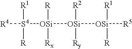 |
| Polymer | R | R2 | R3 | R4 | R5 | x | y |
| 1 | —CH3 | —CH3 | —C6H5 | —CH3 | —C2H3 | 925 | 50 |
| 2 | —CH3 | —CH3 | —C6H5 | —C2H3 | —C2H3 | 809 | 45 |
| 3 | —CH3 | —CH3 | —C6H5 | —C2H3 | —C2H3 | 611 | 41 |
| 4 | —CH3 | —CH3 | —C6H5 | —C2H3 | —C2H5 | 471 | 30 |
| 5 | —CH3 | —CH3 | —CH3 | —C2H3 | —CH3 | 600 | 20 |
| 6 | —CH3 | —CH3 | —CH3 | —C2H3 | —C2H5 | 600 | 20 |
Representative low viscosity organopolysiloxanes of formula (2) suitable for use in preparing a base material include, but are not limited to the following.
| (2) |
 |
| Polymer | R | R2 | R3 | R4 | R6 | x | z |
| 1 | —CH3 | —C2H3 | —C6H5 | —CH3 | —CH3 | 138 | 13 |
| 2 | —CH3 | —C2H3 | —C6H5 | —CH3 | —CH3 | 192 | 39 |
| 3 | —CH3 | —C2H3 | —CH3 | —CH3 | —CH3 | 125 | 25 |
| 4 | —CH3 | —CH3 | —CH3 | —CH3 | —CH3 | 90 | 20 |
| 5 | —CH3 | —CH3 | —CH3 | —CH3 | —CH3 | 125 | 25 |
The base material prepared from the vinyl-containing high viscosity organopolysiloxanes of formula (1) and the low viscosity organopolysiloxanes of formula (2) can be admixed with a copolymer containing dimethyl and methyl hydrogen siloxanes. The amount of hydrogen-containing organopolysiloxane used should be sufficient to achieve a ratio of alkenyl radicals to hydrogen in the uncured composition of less than 1.2.
The elastomers are reinforced with a suitable reinforcing agent or filler such as titanium dioxide, calcium carbonate, lithopone, zinc oxide, zirconium silicate, silica aerogel, iron oxide, diatomaceous earth, silazane-treated silica, precipitated silica, fumed silica, mined silica, glass fibers, magnesium oxide, chromic oxide, zirconium oxide, aluminum oxide, alpha quartz, calcined clay and the like, as well as various reinforcing silica fillers taught in U.S. Pat. No. 3,635,743, the contents of which are hereby incorporated by reference in their entirety, or mixtures of any of the above, or a filler selected from silazane treated silica, precipitated silica and fumed silica or mixtures thereof. In one form, the reinforcing filler is a highly reinforcing silica filler with a surface area ranging from about 80 to about 400 square meters/gram (m2/g), or from about 200 to about 400 m2/g. Typically the reinforcing agent is mixed with the vinyl-containing high viscosity organopolysiloxane (1) and low viscosity organopolysiloxane (2) prior to addition of the hydrogen containing polysiloxane copolymer. The reinforcing filler can be employed in the uncured composition in an amount ranging from 10 parts to about 70 parts per 100 parts of the uncured composition, or from 15 parts to about 40 parts, or from about 20 to about 30 parts. In the cured tacky, reinforced cushioning layer, such amounts correspond to about 10% to about 70% by weight, or from about 15% to about 40%, or from about 20% to about 30%.
The durometer or hardness of the polysiloxane elastomers disclosed herein can be lowered (i.e. made softer) by incorporating low viscosity polysiloxanes into the uncured composition. Representative low viscosity polysiloxanes include polydimethylsiloxane fluids or vinyl-containing polydimethylsiloxane fluids. The molecular weight average of the plasticizer can range from about 750 to about 30,000. The low viscosity polysiloxanes can be employed in an amount ranging from about zero to about 50% by weight of the uncured composition, or from about 10% to about 30%.
The polysiloxane elastomers disclosed herein possess suitable hardness, tensile strength, elongation and tear strength, as based upon standard elastic materials testing. Unreinforced polysiloxane compositions are enclosed in an envelope or other supporting means, i.e. foam impregnation, in order to maintain the shape or durability of an article produced therefrom. In contrast, the high coefficient of friction, tacky, polysiloxane gel pad 30 disclosed herein is viscoelastic and has a measurable hardness, tensile strength, elongation and/or tear strength.
Further, the tacky, reinforced polysiloxanes disclosed herein can retain their elastic properties after prolonged action of compressive stresses, a property known as compression set. Compression set is an indicator of durability. According to ASTM Designation: D395-85, Standard Test Methods for Rubber Property Compression Set, pp. 34-35, the actual stressing service may involve the maintenance of a definite deflection, the constant application of a known force, or the rapidly repeated deformation and recovery resulting from intermittent compressive forces. Though the latter dynamic stressing, like the others, produces compression set, its effects as a whole are simulated more closely by compression flexing or hysteresis tests. Therefore, compression set tests are considered to be mainly applicable to service conditions involving static stresses.
Tests are frequently conducted at elevated temperatures. In a first method utilizing static stresses, a test specimen is compressed to a deflection and maintained under this condition for a specified time and at a specified temperature. In a second method utilizing static stresses, a specified force is maintained under this condition for a specified time and at a specified temperature. After application of the specified deflection or specified force the residual deformation of a test specimen is measured 30 minutes after removal from a suitable compression device in which the specimen has been subjected for a definite time to compressive deformation under specified conditions. After measurement of the residual deformation, the compression set as specified in the appropriate method is calculated according to ASTM D395-85 equations.
When produced in accordance herewith, the gel pad 30 may be prepared to exhibit the following physical properties: a durometer hardness of from about 5 units to about 55 units (Shore 00), a tensile strength of from about 20 psi to about 800 psi, a minimum elongation of from about 250% to about 1100%, a tear strength of from about 5 lb/in to about 200 lb/in, a polyken probe tack of about 10 grams to about 450 grams, a rolling ball tack of about 0 to about 3 inches and a peel test value of from about 0.02 lb/in to about 80 lb/in. The gel pad 30, however, is of course not limited to the above described properties.
The gel pad 30 can be prepared using techniques such as molding, liquid injection molding, transfer molding, casting and the like. The gel pad 30 can be preformed into a desired shape for use with the securement system 10 or gel material may be supplied in a sheet form which may be cut to the desired shape prior to use and attached to the body member 20 a. A gel material may also be provided in a kit form, where a catalyst may is provided in a first container and other components are premixed and provided in a second container. In the kit, a mold is provided and the components may be mixed, poured into the mold, and cured. Curing can be with or without heat.
Such curing can be achieved by increasing the molecular weight of the uncured polysiloxane elastomers to the extent desired through crosslinking, using heating or standing at ambient temperatures, as described U.S. Pat. No. 3,445,420, the contents of which are hereby incorporated by reference in their entirety. Generally, the degree to which the uncured polysiloxane composition can be partially crosslinked can range from about 30% to about 90%, based upon the alkenyl-containing polysiloxane, or from about 30 to about 60%.
In the illustrated embodiment, the gel pad 30 is centered on the body member 20 a, as can be seen in the top view of the securement device 10 in FIG. 2 . In this embodiment, the lateral portions 26 a and 28 a of the bottom surface 22 may be used to secure the securement device 10 to a patient. Of course, the gel pad 30 may be positioned in another location besides being centrally located. In one embodiment in which the gel pad 30 is configured to self adhere to the patient, the gel pad 30 may be coextensive with the entire bottom surface 22 of the body member 20 a.
As can be seen in a side view of the securement device 10 in FIG. 4 , the gel pad 30 protrudes from the body member 20 a. When a medical article is pressed against the gel pad 30, the gel pad will deform at least towards to the body member 20 a and may partially surround or encase at least a portion of the medical article. As can be seen in the side view of the medical device 10 in FIG. 4 and the front view of the medical device 10 in FIG. 5 , the gel pad 30 is configured to have a uniform thickness. In other embodiments, the thickness of the gel pad 30 may fluctuate across the length and/or width of the gel pad 30.
A medical article can be secured to a patient by the securement device 10, as shown in FIGS. 6 and 7 . In the illustrated embodiment, the medical article is a Foley catheter 62 placed on the skin of a patient's leg 64. In the figures, a “longitudinal axis” is generally parallel to a lumen of the medical article. A “transverse axis” is normal to the longitudinal axis and extends in a direction generally parallel to the line shown extending between the securement device 10 and the catheter 62 in FIG. 6 . A “lateral axis” extends normal to both the longitudinal and transverse axes. The “longitudinal direction” refers to a direction substantially parallel to the longitudinal axis; “the transverse direction” refers to a direction substantially parallel to the transverse axis; and “the lateral direction” refers to a direction substantially parallel to the transverse axis.
After placing the securement device 10 above the catheter 62, as shown in FIG. 6 , a medical provider can then lower the securement device 10 over the medial article 62. The medical provider presses the securement device 10 against the patient such that the gel pad 30 presses against the catheter 62 and such that the adhesive on the bottom surface 22 adheres to the skin of the patient's leg 64. The catheter 62 will thus be held on the patient by the securement device 10, as shown in FIG. 7 .
As can be seen in a cross-section view taken along line 8-8 of FIG. 7 , which cross-section view is illustrated in FIG. 8 , the gel pad 30 conforms to the shape of an outer surface of the catheter 62. In this way, the gel pad 30 may at least partially encase the catheter 62 without substantially occluding the catheter 62. As described above in relation to the gel pad 30, the gel pad 30 may return to its original shape when removed from contact with the catheter 62. In other embodiments, the gel pad 30 may substantially retain the shape into which it has conformed. In yet other embodiments, the gel or foam retainer may be formed to have a predefined contour therein to accept a medical article of a certain shape.
Attaching the catheter 62 to the patient in this way inhibits at least lateral movement of the catheter 62. The catheter 62 is at least partially surrounded by the gel pad 30 and abuts the gel pad 30. The gel pad 30 may be in contact with the patient's skin, which may further inhibit motion of the securement device 10, for example due to a tackiness of the gel pad 30. In addition, transverse motion of the catheter 62 is inhibited by the securement device 10 being adhered to the patient.
The securement device 10 may also inhibit longitudinal motion of the catheter 62 when pressed against the medical article. As described above, the gel pad 30 has a tacky property with a high coefficient of friction that inhibits the catheter 62 from sliding longitudinally beneath the securement device 10. In addition, this tacky property will inhibit rotation of the catheter 62. In some embodiments, the portions of the gel pad 30 contacting the patient's skin self adhere to the patient's skin, further securing the medical article on the patient. In the embodiments in which the gel pad 30 is configured to at least partially adhere to the catheter 62, the medical provider may first press the catheter 62 against the gel pad 30 to secure the catheter 62, and then place the combination of the catheter 62 and the securement device 10 onto the skin of the patient, instead of first placing the catheter 62 on the skin of the patient.
The securement device 10 can attach a variety of medical articles, singularly or in combination, in position upon a patient. For example, as can be seen in FIG. 9 , the securement device 10 can be used to hold a medical article different from that of the Foley catheter 62. In the illustrated embodiment, the securement device 10 is shown as securing a catheter hub 66 to the skin of a patient's arm 68. Due to the flexibility of the body member 20 a and the viscoelasticity of the gel pad 30, the securement device can secure any other number of medical devices as well at any number of different positions on the patient. As will be appreciated by one of skill in the art, the configuration of the securement device 10 allows the securement device 10 to not only secure this variety of medical articles, but also to secure them in a variety of different orientations.
In some embodiments, the securement device 10 can be used to hold several medical articles. For example, the gel pad 30 may have a size sufficient to encase several medical articles. In this situation, operation of the securement device 10 is not changed. The securement device 10 can be pressed down over the medical articles to engage the medical articles and adhere to the skin of the patient. The medical articles may or may not be parallel in configuration.
In some embodiments, the securement device 10 is configured to semi-permanently attach to the patient. In other embodiments, the securement device 10 is configured to be removable such that the medical article may be adjusted or replaced, such as with a similar medical article, with a medical article of a different size or shape, or with several medical articles. In this embodiment, the medical provider may peel the securement device 10 from the skin of the patient to remove or reposition the medical article. In some embodiments, the gel pad 30 is configured to be separable from the medical article without leaving a residue, for example, without leaving a sticky deposit on the medical article.
With reference now to FIG. 10A , an embodiment of a securement device 100 includes a body member 20 b and a plurality of gel pads 30 a and 30 b. The gel pads 30 a and 30 b are attached to the body member 20 b, and in the illustrated embodiment the gel pads 30 a and 30 b are configured with a thickness that protrudes from the body member 20 b. For ease of illustration, the securement device 100 is shown upside down in FIG. 10A . Thus, the gel pads 30 a and 30 b are actually attached to a bottom surface of the body member 20 b.
In the illustrated embodiment, the securement device includes two gel pads 30 a and 30 b, which are configured similar to the gel pad 30 described above. In other embodiments, the securement device 100 may include other embodiments of a foam or gel retainer, or both a gel pad and other foam or gel retainer. In some embodiments, the securement device 100 includes more than two gel pads or other foam or gel retainers. The gel pads or other foam or gel retainers may be arranged in any number of configurations on the body member 20 b. The gel pads or other foam or gel retainers may be configured to secure one or more medical articles.
As shown in a top view of the securement device 100 in FIG. 11 , the body member 20 b is configured in a size and shape such that the two gel pads 30 a and 30 b may be attached to the bottom surface 22 of the body member 20 b. As can be seen in front view of the securement device 100 in FIG. 14 , lateral portions 26 b and 28 b of the illustrated embodiment extend beyond the gel pads 30 a and 30 b, respectively, and intermediate portion 29 extends between the gel pads 30 a and 30 b. As will be described in more detail below, the intermediate portion 29 may be configured to contact a portion of a medical article.
The intermediate portion 29 may be configured in any number of lengths. In one embodiment, the intermediate portion 29 is configured to accept a portion of a body of a medical article, for example the body of a winged catheter. In other embodiments, the intermediate portion 29 is configured such that two medicals articles, each secured by one of the gel pads 30 a and 30 b, will be spaced apart at desired or a predetermined distance. Any foam or gel retainers attached to the body member 20 b in addition to the gel pads 30 a and 30 b may be separated from each other and/or the gel pads 30 a and 30 b by similarly or differently configured intermediate portions.
The bottom surface 22 of the body member 20 b comprises an adhesive at one or more of the lateral portions 26 and 28 b and the intermediate portion 29. In the illustrated embodiment, the bottom surface 22 comprises an adhesive that is coextensive with the body member 20 b. Thus, as illustrated, the bottom surface 22 at all of the lateral portions 26 b and 28 b and the intermediate portion 29 comprise an adhesive. In some embodiments, the bottom surface 22 at the intermediate portion 29 comprises an adhesive configured to adhere to a patient's skin. In some embodiments, the bottom surface 22 at the intermediate portion 29 comprises an adhesive configured to adhere to a medical article, or does not comprise any adhesive. In some embodiments, the bottom surface 22 at one or more of the lateral portions 26 b and 28 b does not comprise an adhesive.
As can be seen in a top view of the securement device 100 in FIG. 12 and a side view of the securement device 100 in FIG. 13 , the body member 20 b may otherwise be configured similar to the body member 20 a described above. For example, the ends of the lateral portions 26 b and 28 b may be shaped in various configurations or the body member 20 b may comprise a foam or woven material.
A medical article can be secured to a patient by the securement device 100, as shown in FIGS. 15 and 16 . In the illustrated embodiment, the medical article is shown as a peripherally inserted central catheter (PICC) 102 placed on the skin of the patient's arm 68. The PICC 102 is illustrated as having dual lumens, a body portion 104, and wings 106 a and 106 b projecting laterally from the body portion 104.
The method of attaching a medical article to a patient using the securement device 100 is similar to the method of attaching a medical article to a patient using the securement device 10. When contacting the medical article with the securement device 100, however, the gel pads 30 a and 30 b may be arranged in a number of different configurations with respect to the medical article. In the embodiment illustrated in FIG. 16 , the securement device 100 is placed laterally over the PICC 102 to cover the wings 106 a and 106 b and a segment of the body portion 104.
As can be seen in a cross-section view taken along line 17A-17A of FIG. 16 , which cross-section view is illustrated in FIG. 17A , gel pads 30 a and 30 b may conform to the shape of the wings 106 a and 106 b. The gel pads 30 a and 30 b are shown as being compressed in the transverse direction and as surrounding lateral facing surfaces of the wings 106 a and 106 b, which may inhibit at least lateral movement of the PICC 102. In the illustrated embodiment, the body portion 104 is located between the gel pads 30 a and 30 b so as to contact the bottom surface 22 of the body member 20 b at the intermediate portion 29. The bottom surface 22 at the intermediate portion may comprise an adhesive configured to attach to a medical article. Adhering the securement device 100 to the PICC 102 may aid in securement of the PICC 102 and inhibit lateral and/or longitudinal motion of the PICC 102. In other embodiments, the adhesive of the bottom surface 22 at the intermediate portion 29 may be omitted, or the bottom surface 22 at the intermediate portion 29 may be otherwise configured to avoid adhering to the PICC 102.
As can be seen in a cross-section view taken along line 17B-17B of FIG. 16 , which cross-section view is illustrated in FIG. 17B , gel pad 30 b may surround longitudinally facing surfaces of the wing 106 b. Longitudinally facing surfaces of the wing 106 a may similarly be surrounded by the gel pad 30 a. Such configuration may further inhibit at least longitudinal motion of the PICC 102, for example by placing such longitudinally facing surfaces of the wings 106 a and/or 106 b in abutment with the gel pad 30 a and/or 30 b. In other embodiments, the gel pads 30 a and 30 b may only surround one longitudinally facing surface of one or more of the wings 106 a and 106 b or no longitudinally facing surface.
In FIG. 17B , the body member 20 b is illustrated as having a size such that the body member is not in contact with the patient's skin on either side of the longitudinally facing surfaces of the wing 106 b. The body member 20 b, however, may be of a size or shape such that the body member 20 b will extend sufficient beyond the gel pad 30 b to contact the skin of the patient's skin on one or more of these sides. The body member 20 b may be similarly configured with respect to the gel pad 30 a.
In other embodiments, the PICC 102 may be arranged such that one or more of the wings 106 a and 106 b contact the body portion 104. Additionally, the securement device 100 could be placed longitudinally over the PICC 102. In such placement, the gel pads 30 a and 30 b may each contact a portion of a lumen of the PICC 102, while the intermediate portion 29 may contact the body portion 104. In yet other embodiments, a single gel pad attached to the body member 20 b could contact the securement device 100, and the single gel pad may have a size sufficient to both laterally and longitudinally surround the securement device 100. These embodiments are merely example configurations of course, and as described above the securement device 100 may be configured with any number of foam or gel retainers and may be placed in a multitude of different configurations to secure many types of medical articles. Use of the securement device 100 to secure such medical articles will not occlude the medical articles, and more than one medical article may be secured at a time.
With reference now to FIG. 18A , an embodiment of a securement device 180 includes a body member 20 c and a gel pad 30 c. The gel pad 30 c is attached to the body member 20 c, and in the illustrated embodiment the gel pad 30 c is configured with a thickness that protrudes from the body member 20 c. The gel pad 30 c is configured similar to the gel pad 30, illustrated in FIG. 1A .
The bottom surface 22 of the body member 20 c, shown in a bottom view of the securement device 180 in FIG. 19 , comprises an adhesive. As described above in reference to the securement device 10 and the body member 20 a, the body member 20 c may be configured as an adhesive dressing, or an adhesive may be coated onto the bottom surface 22. In the illustrated embodiment, the adhesive is formed over the extent of the bottom surface 22. In other embodiments, the adhesive may only partially cover the bottom surface 22, and may be formed in various patterns and shapes. The adhesive comprises a compound configured to adhere to the skin of a patient, as described above.
As can be seen in a top view of the securement device 180 in FIG. 20 , the gel pad 30 c is attached to the top surface 24 of the body member 20 c. In the illustrated embodiment, the gel pad 30 c is approximately centered on the body member 20 c. In other embodiments, the gel pad 30 c may be off-centered. In some embodiments, a plurality of gel pads may be attached to the top surface 24. The plurality of gel pads may be configured to secure one or more medical articles. The top surface 24 forms a mounting surface for attachment of other securement devices, as described in more detail below. In some embodiments, a portion of the top surface 24 comprises an adhesive.
As can be seen in a side view of the securement device 180 in FIG. 21 and a front view of the securement device 180 in FIG. 22 , the body member 20 c is illustrated as being approximately square. In other embodiments, the body member 20 c may be configured in other shapes. The illustrated square shape, however, may be advantageous when attaching other securement devices, as described in more detail below. The body member 20 c may otherwise be configured similar to the body member 20 a, illustrated in FIG. 1A .
A medical article can be secured to a patient by using the securement device 180 and another securement device, as shown in FIGS. 23 and 24 . In the illustrated embodiment, the medical article 182 includes a lumen configured to transport liquids, and the other securement device is the securement device 10 illustrated in FIG. 1A .
In FIG. 23 , the securement device 180 is adhered to the patient's arm 68. After placing the medical article 182 above the securement device 180, a medical provider can then lower the medical article 182 onto the securement device 180 such that the medical article 182 is in contact with the gel pad 30 c. Then, the securement device 10 may be lowered over the medial article 182 and pressed against the securement device 180 to attach the securement device 10 to the securement device 180 and secure the medical article 182. The medical article 182 will thus be held on the patient, as shown in FIG. 24 . Of course, the medical provider may first attach the medical article 182 to the securement device 10 and then attach the combination of the securement device 10 and the medical article 182 to the securement device 180 in embodiments where the gel pad of the securement device 10 is configured to self-adhere to the medical article 182.
As described above, the top surface 24, see FIG. 20 , forms a mounting surface. The mounting surface is configured such that a securement device may be attached to thereto. In the illustrated embodiment, the mounting surface is free of adhesives, and comprises a surface on which a securement device may be adhered. The mounting surface may be smooth, glossy, or textured, or otherwise configured such that a securement device may be adhered thereto. In other embodiments, the mounting surface may comprise an adhesive to attach to a securement device placed thereon.
The mounting surface may be configured such that an attached securement device may be detached or removed. For example, the mounting surface may be configured as a smooth surface from which the securement device 10 may be peeled without damaging the securement device 180. In some embodiments, a securement device that has been removed from the mounting surface may be reattached. Those skilled in the art will appreciate that repeated removal and reattachment of securement devices and/or medical articles to the mounting surface will not cause discomfort to the patient, and that the mounting surface shield the patient's skin from excoriation. Of course, in some embodiments the mounting surface and/or an adhesive or other attachment feature of an attaching securement device may be configured to permanently attach to the mounting surface.
The mounting surface is not limited to attaching or coupling with a securement device using adhesives. For example, the mounting surface may comprise hook and/or loop fasteners configured to engage a securement device. In one embodiment, the mounting surface has snap fasteners configured to engage snap fasteners on a securement device. In some embodiments, a portion of a securement device may be permanently or semi-permanently attached to the mounting surface such that another portion of the securement device can be rotated, folded, or bent over a medical article and secured to the mounting surface.
In the illustrated embodiment, the body member 20 c is configured such that the securement device 10 can be secured over the gel pad 30 c in any configuration or rotation. In other embodiments, the body member 20 c is configured in another size or shape that also allows securement of the securement device 10 over the gel pad 30 c in any configuration or rotation. For example, the body member 20 c may be configured in the shape of a circle. In some embodiments, the size and/or shape of the body member 20 c may be more closely matched with the size and/or shape of the securement device 10. In such embodiment, there may be a limited number of configurations for attaching the securement device 10 to the mounting surface and over the gel pad 30 c.
As can be seen in a cross-section view taken along line 25-25 of FIG. 24 , which cross-section view is illustrated in FIG. 25 , both the gel pad 30 of the securement device 10 and the gel pad 30 c of the securement device 180 may conform to the shape of an outer surface of the lumen 182. In this way, the gel pad 30 and the gel pad 30 c may in combination at least partially encase the medical article 182 without substantially occluding the lumen. Securing the medical article 182 in this configuration inhibits motion. For example, lateral, longitudinal, transverse, and/or rotational movement of the medical article 182 may be inhibited in this configuration.
Those skilled in the art will recognize that although the securement device 180 is illustrated in combination with the securement device 10 in FIG. 25 , other securement devices besides the securement device 10 may be used in combination with the securement device 180 or portions thereof.
Although the securement device 180 is illustrated as securing a medical article 182 having a tubular shape, the securement device 180 can be used to secure a variety of medical articles, singularly or in combination, in position upon a patient. The securement device 180 and/or another securement device used in combination with the securement device 180 may comprise one or more gel pads. For example, the securement device 180 may be used in combination with the securement device 100. When using the securement device 100 with the securement device 180, the securement device 100 can be adhered to the securement device 180 over a medical article such that the gel pad 30 c approximately aligns with the intermediate portion 29 of the securement device 100. In some embodiments, the gel pad 30 c is configured to self-adhere to a medical article such that a medical article can be secured to the securement device 180 without the need for another securement device. The securement device 180 may be packaged in a kit including one or more other securement devices.
With reference now to FIG. 28A , an embodiment of a securement device 280 includes the body member 20 a and a gel pad 30 d. The gel pad 30 d is attached to the body member 20 a. The gel pad 30 d is configured similar to the gel pad 30, illustrated in FIG. 1A , with the exceptions of the gel pad 30 d being thicker and formed with a channel 282 therethrough. For ease of illustration, the securement device 280 is shown upside down in FIG. 28A . Thus, the gel pad 30 d is actually attached to a bottom surface of the body member 20 a.
As can be seen in a front view of the securement device 280 in FIG. 29 , the channel 282 is illustrated as having a circular cross-sectional shape and extends along the longitudinal axis. In the illustrated embodiment, the channel 282 is configured to accept a tubular medical article, but in other embodiments the channel 282 has any number of shapes and sizes. In addition, the shape or size of a cross-section of the channel may vary along the length of the channel. Additionally, the channel may be formed in a shape which does not follow the longitudinal axis. For example, a curved channel may aid in proper placement of a medical article or may keep the medical article in a configuration that will not interfere with a medical practitioner aiding a patient to which the securement device 280 is attached. A plurality of the gel pads 30 d may be attached to the body member 20 a, or a combination of gel pads with channels and gel pads without channels may be attached to the body member 20 a.
A medical article can be secured to a patient by the securement device 280, as shown in FIGS. 30 and 31 . In the embodiment shown in FIG. 30 , the securement device 280 is illustrated as being placed above the patient's arm 68 with the medical article 182 passing through the channel 282. A medical provider can lower the securement device 280 onto the patient's arm 68 and press the securement device 280 against the patient such that the gel pad 30 d presses against the medical article 182 and such that the adhesive on the body member 20 a adheres to the skin of the patient's arm 68. The medical article 182 will thus be held on the patient by the securement device 280, as shown in FIG. 31 .
As can be seen in a cross-section view taken along line 32-32 of FIG. 31 , which cross-section view is illustrated in FIG. 32 , the gel pad 30 d conforms to the shape of an outer surface of the medical article 182. As a result, a variety of medical articles of varying diameter may be accepted within the channel 282 and secured by the securement device 280. Such secured medical articles will be inhibited from moving in at least a transverse direction, and may further be inhibited from moving in a lateral and/or longitudinal direction.
In the illustrated embodiment, the area between the gel pad 30 d and the medical article 182 is filled in with a spray material 320. The spray material may comprise spray foam or gel, such as spray memory foam or a spray-in-the-can alginate. The securement device 280 may be packaged in the form of a kit including the spray foam or gel. Of course, the spray material 320 may be omitted when securing a medical article using the securement device 280. A gel material may be used to fill in an area between any of the gel pads 30, 30 a, 30 b, and 30 c and a patient's skin, and/or to fill in an area between any of the gel pads 30, 30 a, 30 b, and 30 c and another gel pad or surface. The securement devices 10, 100, and 180 may similarly be packaged with a spray foam or gel.
Various aspects are described above with reference to specific forms or embodiments selected for purposes of illustration. It will be appreciated that the spirit and scope of the disclosed securement system is not limited to the selected forms. Moreover, it is to be noted that the figures provided are not drawn to any particular proportion or scale, and that many variations can be made to the illustrated embodiments. Thus, although the system has been disclosed in the context of certain preferred embodiments and examples, it will be understood by those skilled in the art that the present invention extends beyond the specifically disclosed embodiments to other alternative embodiments and/or uses of the invention and obvious modifications and equivalents thereof. In addition, while a number of variations have been shown and described in detail, other modifications, which are within the scope of this invention, will be readily apparent to those of skill in the art based upon this disclosure.
It is also contemplated that various combinations or sub-combinations of the specific features and aspects of the embodiments may be made and still fall within the scope of the invention. Accordingly, it should be understood that various features and aspects of the disclosed embodiments can be combined with or substituted for one another in order to form varying modes of the disclosed invention. Thus, it is intended that the scope of the present invention herein disclosed should not be limited by the particular disclosed embodiments described above, but should be determined only by a fair reading of the disclosure and the claims that follow.
Although the above embodiments and devices, systems, and methods have been described in terms of use in medical device applications, those skilled in relevant arts will recognize that such embodiments, devices, systems, and methods can be employed with any suitable non-medical applications and in some instances may be configured for use with animals.
All patents, test procedures, and other documents cited herein, including priority documents, are fully incorporated by reference to the extent such disclosure is not inconsistent with this invention and for all jurisdictions in which such incorporation is permitted.
Claims (27)
1. A securement device for a medical device, comprising:
a body having a top surface and a bottom surface, said bottom surface having an adhesive compound thereon; and
a resilient retainer formed from a soft, tacky elastomeric gel or an elastomeric foam and being supported by said body, said resilient retainer having a channel extending along a longitudinal axis, said channel being adapted for receiving and securing a medical device, the medical device being secured to the skin of a patient upon affixing said bottom surface to the patient via said adhesive compound, wherein said elastomeric gel is formed by curing an organopolysiloxane composition.
2. The securement device of claim 1 , wherein said medical device is a catheter.
3. The securement device of claim 1 , wherein said channel is preformed into a desired shape for receiving and securing the medical device.
4. The securement device of claim 3 , wherein a space between said channel and the medical device is filled with a gel or foam.
5. The securement device of claim 4 , wherein said gel or foam comprises spray gel or foam.
6. The securement device of claim 1 , wherein said organopolysiloxane composition comprises:
a vinyl-containing high viscosity organopolysiloxane or a blend of high viscosity vinyl-containing organopolysiloxanes;
a low viscosity organopolysiloxane or a blend of low viscosity organopolysiloxanes;
a reinforcing filler;
a platinum catalyst; and
a hydrogen containing polysiloxane copolymer,
wherein a molar ratio of hydrogen to vinyl radicals in the total composition is less than 1.2, such that after curing, the degree to which said tacky, reinforced polysiloxane elastomer is partially crosslinked is about 30 to about 90%.
7. The securement device of claim 6 , wherein the organopolysiloxane composition has a hardness of about 5 to about 55 durometer units (Shore 00), a tackiness of about 0 to about 450 grams as determined by a polyken probe tack tester or about 0 to about 7.6 cm as determined by a rolling ball tack tester and a tensile strength of about 0.14 to about 5.52 mega Pascals, a minimum elongation of about 250 to about 1100 percent and a tear strength of about 0.8 to about 35.2 kN/m.
8. The securement device of claim 1 , wherein the organopolysiloxane composition comprises, based upon 100 parts total composition:
20 to 90 parts of a vinyl-containing high viscosity organopolysiloxane or a blend of high viscosity vinyl-containing organopolysiloxanes having no more than 25 mole percent of phenyl radicals and having a viscosity of 2,000 to 1,000,000 centipoise at 25° C. of the formula:

where R1 is selected from the class consisting of alkenyl, alkyl and aryl radicals and R is a monovalent hydrocarbon radical, R2 is selected from the class consisting of alkyl and aryl radicals, R4 and R5 are independently selected from the class consisting of alkyl and vinyl radicals; x varies from zero to 3000; and y varies from 0 to 300;
from 5 to 40 parts of a polymer selected from the class consisting of a low viscosity organopolysiloxane and a blend of low viscosity organopolysiloxanes having viscosity that varies from 20 to 5,000 centipoise at 25° C. and having no more than 25 mole percent phenyl radicals of the formula

wherein R1 and R6 are independently selected from the class consisting of alkenyl, alkyl and aryl radicals, R2 and R are as previously defined, R3 is selected from the class consisting of alkyl, aryl and alkenyl radicals, w varies from 0 to 500, and z varies from 0 to 200;
from 10 to 70 parts of a reinforcing filler;
from 0.1 to 50 parts per million of platinum catalyst (as platinum metal) to the total composition; and
from 0.1 to 50 parts of a hydrogen containing polysiloxane copolymer,
wherein the molar ratio of hydrogen to alkenyl radicals in the total uncured composition is less than 1.2, such that after curing, the degree to which the soft, tacky, reinforced polysiloxane elastomer is partially crosslinked is about 30 to about 90%.
9. The securement device of claim 1 , wherein said elastomeric foam is a memory foam comprising polyurethane.
10. A method of securing a medical device to a patient, comprising:
providing a securement device for the medical device, and including a body having a top surface and a bottom surface, the bottom surface having an adhesive compound thereon, and a retainer formed from a soft, tacky elastomeric gel or an elastomeric foam, the retainer being supported by the bottom surface of the body and having a channel extending along a longitudinal axis, said channel being adapted for receiving a medical device, wherein the elastomeric gel is formed by curing an organopolysiloxane composition;
locating the medical device on the resilient retainer; and
securing the securement device and medical device to the patient with the body via the adhesive compound.
11. The method of claim 10 , wherein the medical device is a catheter.
12. The method of claim 10 , wherein the channel has a size and shape to receive at least a portion of the medical device.
13. The method of claim 12 further comprising filling a space between the channel and the medical device with a gel or foam.
14. The method of claim 13 , wherein the gel or foam comprises spray gel or foam.
15. The method of claim 10 , wherein said organopolysiloxane composition comprises:
a vinyl-containing high viscosity organopolysiloxane or a blend of high viscosity vinyl-containing organopolysiloxanes;
a low viscosity organopolysiloxane or a blend of low viscosity organopolysiloxanes;
a reinforcing filler;
a platinum catalyst; and
a hydrogen containing polysiloxane copolymer,
wherein a molar ratio of hydrogen to vinyl radicals in the total composition is less than 1.2, such that after curing, the degree to which said tacky, reinforced polysiloxane elastomer is partially crosslinked is about 30 to about 90%.
16. The method of claim 15 , wherein the organopolysiloxane composition has a hardness of about 5 to about 55 durometer units (Shore 00), a tackiness of about 0 to about 450 grams as determined by a polyken probe tack tester or about 0 to about 7.6 cm as determined by a rolling ball tack tester and a tensile strength of about 0.14 to about 5.52 mega Pascals, a minimum elongation of about 250 to about 1100 percent and a tear strength of about 0.8 to about 35.2 kN/m.
17. The method of claim 10 , wherein the organopolysiloxane composition comprises, based upon 100 parts total composition:
20 to 90 parts of a vinyl-containing high viscosity organopolysiloxane or a blend of high viscosity vinyl-containing organopolysiloxanes having no more than 25 mole percent of phenyl radicals and having a viscosity of 2,000 to 1,000,000 centipoise at 25° C. of the formula:

where R1 is selected from the class consisting of alkenyl, alkyl and aryl radicals and R is a monovalent hydrocarbon radical, R2 is selected from the class consisting of alkyl and aryl radicals, R4 and R5 are independently selected from the class consisting of alkyl and vinyl radicals; x varies from zero to 3000; and y varies from 0 to 300;
from 5 to 40 parts of a polymer selected from the class consisting of a low viscosity organopolysiloxane and a blend of low viscosity organopolysiloxanes having viscosity that varies from 20 to 5,000 centipoise at 25° C. and having no more than 25 mole percent phenyl radicals of the formula

wherein R1 and R6 are independently selected from the class consisting of alkenyl, alkyl and aryl radicals, R2 and R are as previously defined, R3 is selected from the class consisting of alkyl, aryl and alkenyl radicals, w varies from 0 to 500, and z varies from 0 to 200;
from 10 to 70 parts of a reinforcing filler;
from 0.1 to 50 parts per million of platinum catalyst (as platinum metal) to the total composition; and
from 0.1 to 50 parts of a hydrogen containing polysiloxane copolymer,
wherein the molar ratio of hydrogen to alkenyl radicals in the total uncured composition is less than 1.2, such that after curing, the degree to which the soft, tacky, reinforced polysiloxane elastomer is partially crosslinked is about 30 to about 90%.
18. The method of claim 10 , wherein said elastomeric foam is a memory foam comprising polyurethane.
19. A securement system, comprising:
a flexible body member having a first surface and a second surface located opposite the first surface, the first surface comprising an adhesive configured for attachment to a patient; and
a tacky gel pad supported by the flexible body member and configured to form a channel extending along a longitudinal axis when pressed against a medical article, the gel pad inhibiting at least lateral and longitudinal motion of the medical article when the flexible body member is attached to the patient, wherein said gel pad is formed by curing an organopolysiloxane composition.
20. The securement system of claim 19 , comprising a plurality of tacky gel pads configured to deform when pressed against the medical article.
21. The securement system of claim 19 further comprising an anchor pad having a top surface and a bottom surface, the top surface comprising a mounting surface configured for attachment to the flexible body member, the bottom surface comprising an adhesive configured for attachment to the patient's skin.
22. The securement system of claim 21 , comprising a plurality of flexible body members and a plurality of gel pads, wherein the mounting surface is configured for attachment to the plurality of flexible body members.
23. The securement system of claim 21 , wherein the flexible body member is releasably attached to the mounting surface.
24. The securement system of claim 19 , wherein the tacky gel pad is attached to the first surface of the flexible body member.
25. The securement system of claim 19 , wherein the tacky gel pad is attached to the second surface of the flexible body member.
26. A securement device for a medical device, comprising:
a body having a top surface and a bottom surface, said bottom surface having an adhesive compound thereon; and
a resilient retainer formed from a soft, tacky elastomeric gel or an elastomeric foam and being supported by said body, said resilient retainer having a channel extending along a longitudinal axis, said channel being adapted for receiving and securing a medical device, the medical device being secured to the skin of a patient upon affixing said bottom surface to the patient via said adhesive compound, wherein said elastomeric foam is a memory foam comprising polyurethane.
27. A method of securing a medical device to a patient, comprising:
providing a securement device for the medical device, and including a body having a top surface and a bottom surface, the bottom surface having an adhesive compound thereon, and a retainer formed from a soft, tacky elastomeric gel or an elastomeric foam, the retainer being supported by the bottom surface of the body and having a channel extending along a longitudinal axis, said channel being adapted for receiving a medical device, wherein said elastomeric foam is a memory foam comprising polyurethane;
locating the medical device on the resilient retainer; and
securing the securement device and medical device to the patient with the body via the adhesive compound.
Priority Applications (3)
| Application Number | Priority Date | Filing Date | Title |
|---|---|---|---|
| US12/470,434 US8394067B2 (en) | 2009-05-21 | 2009-05-21 | Medical device securement system |
| US13/762,803 US10322262B2 (en) | 2009-05-21 | 2013-02-08 | Medical device securement system |
| US16/394,969 US20190247625A1 (en) | 2009-05-21 | 2019-04-25 | Medical Device Securement System |
Applications Claiming Priority (1)
| Application Number | Priority Date | Filing Date | Title |
|---|---|---|---|
| US12/470,434 US8394067B2 (en) | 2009-05-21 | 2009-05-21 | Medical device securement system |
Related Child Applications (1)
| Application Number | Title | Priority Date | Filing Date |
|---|---|---|---|
| US13/762,803 Continuation US10322262B2 (en) | 2009-05-21 | 2013-02-08 | Medical device securement system |
Publications (2)
| Publication Number | Publication Date |
|---|---|
| US20100298778A1 US20100298778A1 (en) | 2010-11-25 |
| US8394067B2 true US8394067B2 (en) | 2013-03-12 |
Family
ID=43125051
Family Applications (3)
| Application Number | Title | Priority Date | Filing Date |
|---|---|---|---|
| US12/470,434 Active 2031-08-03 US8394067B2 (en) | 2009-05-21 | 2009-05-21 | Medical device securement system |
| US13/762,803 Active 2032-11-28 US10322262B2 (en) | 2009-05-21 | 2013-02-08 | Medical device securement system |
| US16/394,969 Pending US20190247625A1 (en) | 2009-05-21 | 2019-04-25 | Medical Device Securement System |
Family Applications After (2)
| Application Number | Title | Priority Date | Filing Date |
|---|---|---|---|
| US13/762,803 Active 2032-11-28 US10322262B2 (en) | 2009-05-21 | 2013-02-08 | Medical device securement system |
| US16/394,969 Pending US20190247625A1 (en) | 2009-05-21 | 2019-04-25 | Medical Device Securement System |
Country Status (1)
| Country | Link |
|---|---|
| US (3) | US8394067B2 (en) |
Cited By (16)
| Publication number | Priority date | Publication date | Assignee | Title |
|---|---|---|---|---|
| US20130204190A1 (en) * | 2012-02-07 | 2013-08-08 | Marie-Andrea I. Wilborn | Intravenous splint cover and associated methods |
| US20160015939A1 (en) * | 2014-07-21 | 2016-01-21 | James T. Rawls | Absorbent and antimicrobial cuff for catheter placement |
| WO2016164598A3 (en) * | 2015-04-07 | 2017-01-05 | Tamer Elsamahy | Catheter stabilization device and method of use |
| US9616200B2 (en) | 2005-12-21 | 2017-04-11 | Venetc International, Inc. | Intravenous catheter anchoring device |
| US9642987B2 (en) | 2005-08-31 | 2017-05-09 | C.R. Bard, Inc. | Anchoring system for a catheter |
| US20170311849A1 (en) * | 2014-11-11 | 2017-11-02 | Innovaura Corporation | Heart rate monitor |
| US9878129B2 (en) | 2013-05-14 | 2018-01-30 | Daniel Larkin | Infusion site retainer for maintaining infusion tubing |
| US9895514B2 (en) | 2014-01-27 | 2018-02-20 | Maddoc Medical Products, Inc. | Medical device securement system and method |
| US9950143B2 (en) | 2012-02-07 | 2018-04-24 | Marie Andrea I. Wilborn | Intravenous splint cover and associated methods |
| US10322262B2 (en) | 2009-05-21 | 2019-06-18 | C. R. Bard, Inc. | Medical device securement system |
| USD859649S1 (en) * | 2014-03-17 | 2019-09-10 | Nexus Control Systems, Llc | Catheter holding device |
| USD964571S1 (en) | 2019-05-28 | 2022-09-20 | Maddoc Medical Products, Inc. | Catheter securement pad |
| US11452848B2 (en) | 2019-04-17 | 2022-09-27 | Bard Access Systems, Inc. | Catheter securement device including extended anchor pad and release liner clasping features |
| USD975855S1 (en) | 2021-03-25 | 2023-01-17 | Maddoc Medical Products, Inc. | Catheter securement pad |
| US11648377B2 (en) | 2016-05-13 | 2023-05-16 | C. R. Bard, Inc. | Catheter securement device including a guiding nose |
| US11896783B2 (en) | 2016-12-27 | 2024-02-13 | Vasonics, Inc. | Catheter housing |
Families Citing this family (22)
| Publication number | Priority date | Publication date | Assignee | Title |
|---|---|---|---|---|
| US8834425B2 (en) | 2007-07-16 | 2014-09-16 | C.R. Bard, Inc. | Securement system employing polymeric gel |
| US8381731B2 (en) * | 2010-04-16 | 2013-02-26 | Jonathon Sedrick Jundt | Medical tubing stabilization device |
| US20140163505A1 (en) * | 2011-04-04 | 2014-06-12 | Sessions Pharmaceuticals Inc. | Wound Dressing |
| US20140364838A1 (en) * | 2012-06-26 | 2014-12-11 | iMed Technology, Inc. | Nasal retention system including a foam clip |
| US9550043B2 (en) * | 2012-12-13 | 2017-01-24 | Interrad Medical, Inc. | Systems and methods for anchoring medical devices |
| WO2014107233A1 (en) * | 2013-01-02 | 2014-07-10 | Kci Licensing, Inc. | A medical drape having an ultra-thin drape film and a thick adhesive coating |
| US9248259B2 (en) | 2013-08-14 | 2016-02-02 | Tidi Securement Products, Llc | Double notched catheter securement assembly |
| US10576251B2 (en) * | 2014-03-13 | 2020-03-03 | TDI Products, LLC | Offset catheter securement device with removable retention member |
| USD864384S1 (en) | 2014-03-13 | 2019-10-22 | Tidi Products, Llc | Split-loop offset catheter securement device |
| US9358366B2 (en) * | 2014-03-13 | 2016-06-07 | Tidi Securement Products, Llc | Offset catheter securement device |
| US10350388B2 (en) | 2014-09-05 | 2019-07-16 | Tidi Securement Products, Llc | Peripheral intravenous and arterial catheter securement device |
| USD842986S1 (en) | 2014-09-05 | 2019-03-12 | Tidi Products, Llc | Narrow IV securement device |
| USD780914S1 (en) | 2014-09-05 | 2017-03-07 | Tidi Products, Llc | Catheter adhesive device |
| US11213722B2 (en) * | 2015-11-25 | 2022-01-04 | Swimmetric, LLC | Swimming speedometer system with near-eye display |
| USD834711S1 (en) | 2016-02-04 | 2018-11-27 | Tidi Products, Lcc | Catheter and connector securement device |
| USD789527S1 (en) | 2016-02-04 | 2017-06-13 | Tidi Products, Llc | Catheter and connector securement device |
| US10773057B1 (en) * | 2016-02-16 | 2020-09-15 | M.C. Johnson Company, Inc. | Medical appliance securement device |
| USD816833S1 (en) | 2017-01-10 | 2018-05-01 | Tidi Products, Llc | Access needle securement device |
| CN110636820A (en) * | 2017-05-19 | 2019-12-31 | 3M创新有限公司 | Medical article securement devices comprising viscoelastic polymers |
| CA3075489A1 (en) | 2017-09-12 | 2019-03-21 | Isl, Llc | Devices and methods for contacting living tissue |
| US20210030944A1 (en) * | 2018-02-05 | 2021-02-04 | Stryker European Holdings I, Llc | Apparatus And Method For Securing An Elongate Member To A Medical Instrument |
| GB2575488A (en) | 2018-07-12 | 2020-01-15 | Univ Limerick | A securement device |
Citations (96)
| Publication number | Priority date | Publication date | Assignee | Title |
|---|---|---|---|---|
| US3167072A (en) | 1962-10-11 | 1965-01-26 | Stone Hester Ellen | Intravenous needle and flow tube stabilizing means |
| US3700574A (en) * | 1966-07-26 | 1972-10-24 | Grace W R & Co | Photocurable liquid polyene-polythiol polymer composition |
| US3834380A (en) | 1972-11-15 | 1974-09-10 | W Boyd | Holder for intravenous injection cannula and tubing |
| US3993081A (en) | 1975-01-23 | 1976-11-23 | Swesco Inc. | Endotracheal tube holder |
| JPS524691A (en) | 1975-08-18 | 1977-01-13 | Enzeru Kk | Sanitary napkin |
| US4059105A (en) * | 1976-03-24 | 1977-11-22 | Omnimed, Inc. | Cannula securing device |
| US4082094A (en) | 1976-09-13 | 1978-04-04 | Dailey Calvin L | Locking device for intravenous insert |
| US4114618A (en) | 1976-12-15 | 1978-09-19 | Vargas Jorge J | Catheter assembly |
| US4129128A (en) | 1977-02-23 | 1978-12-12 | Mcfarlane Richard H | Securing device for catheter placement assembly |
| US4161177A (en) | 1976-02-12 | 1979-07-17 | Intermedicat Gmbh | Catheter attachment |
| US4170995A (en) | 1977-11-21 | 1979-10-16 | Levine Robert A | Catheter clamp |
| US4224937A (en) | 1979-01-19 | 1980-09-30 | Whitman Medical Corporation | Stabilizing fitting for an intravenous catheter |
| US4250880A (en) | 1979-06-08 | 1981-02-17 | Whitman Medical Corporation | Stabilizing fitting for an intravenous catheter |
| US4333468A (en) | 1980-08-18 | 1982-06-08 | Geist Robert W | Mesentery tube holder apparatus |
| US4356599A (en) | 1980-12-19 | 1982-11-02 | Minnesota Mining And Manufacturing Company | Stackable flat cable clamp |
| US4362156A (en) | 1979-04-18 | 1982-12-07 | Riverain Corporation | Intravenous infusion assembly |
| US4389754A (en) | 1981-02-13 | 1983-06-28 | Nikko Kogyo Kabushiki Kaisha | Binding device |
| US4397647A (en) | 1979-01-19 | 1983-08-09 | Whitman Medical Corporation | Catheter stabilization fitting having a snap-over cover |
| US4405163A (en) | 1979-12-12 | 1983-09-20 | Intermedicat Gmbh | Coupling for medical apparatus tubes |
| US4453933A (en) | 1981-11-24 | 1984-06-12 | Speaker Mark G | Intravenous device |
| US4480639A (en) | 1982-01-18 | 1984-11-06 | Peterson Edward D | Medical tube retaining device |
| US4500338A (en) * | 1980-09-03 | 1985-02-19 | Young Robert W | Adherent controlled release microbiocides containing hydrolyzable _organic titanium compounds |
| US4533349A (en) | 1982-11-08 | 1985-08-06 | Medical Engineering Corporation | Skin mounted drainage catheter retention disc |
| US4621029A (en) * | 1984-01-17 | 1986-11-04 | Fuji Systems Corporation | Medical sealant for skin |
| US4623102A (en) | 1983-12-14 | 1986-11-18 | Apple Adhesives, Inc. | Article clamp |
| US4636552A (en) * | 1984-05-30 | 1987-01-13 | Rhone-Poulenc Recherches | Novel silicone/polylactone graft copolymer |
| US4659329A (en) | 1984-07-27 | 1987-04-21 | The Kendall Company | Liquid drainage system |
| US4711636A (en) | 1985-11-08 | 1987-12-08 | Bierman Steven F | Catheterization system |
| US4733666A (en) | 1986-01-13 | 1988-03-29 | Texas Tech University Health Sciences Center | Surgical clip for cholangiography |
| JPS63501477A (en) | 1985-05-03 | 1988-06-09 | メディカル・ディストリビューターズ・インコーポレーテッド | General purpose clamp |
| US4775121A (en) | 1987-07-20 | 1988-10-04 | Carty James F | Cable clamp |
| US4852844A (en) | 1988-04-25 | 1989-08-01 | Villaveces James W | Device for aiding in preparation of intravenous therapy |
| US4857058A (en) | 1988-07-11 | 1989-08-15 | Payton Hugh W | Support patch for intravenous catheter |
| JPH01308572A (en) | 1988-06-07 | 1989-12-13 | Nippon Sherwood Kk | Catheter fixing jig |
| US4897082A (en) | 1989-03-20 | 1990-01-30 | Becton, Dickinson And Company | Apparatus for providing a suture tab |
| US4898587A (en) | 1988-11-15 | 1990-02-06 | Mera Csaba L | Intravenous line stabilizing device |
| US4919654A (en) | 1988-08-03 | 1990-04-24 | Kalt Medical Corporation | IV clamp with membrane |
| US4997421A (en) | 1986-12-10 | 1991-03-05 | Dale Medical Products, Inc. | IV connector lock and stabilizer |
| US5037397A (en) | 1985-05-03 | 1991-08-06 | Medical Distributors, Inc. | Universal clamp |
| US5084026A (en) | 1989-07-14 | 1992-01-28 | Shapiro Robert A | Intravenous apparatus holder |
| US5098399A (en) | 1990-02-07 | 1992-03-24 | Tollini Dennis R | Medical securing tape |
| US5192274A (en) | 1991-05-08 | 1993-03-09 | Bierman Steven F | Anchor pad for catheterization system |
| US5192273A (en) | 1989-07-24 | 1993-03-09 | Steven F. Bierman | Catheterization system |
| US5226892A (en) | 1991-08-23 | 1993-07-13 | Boswell Thomas A | Surgical tubing clamp |
| US5266401A (en) | 1992-11-25 | 1993-11-30 | Tollini Dennis R | Securing tape |
| US5308337A (en) | 1993-03-16 | 1994-05-03 | Bingisser Timothy A | Medical tube clip device |
| US5334186A (en) | 1992-11-09 | 1994-08-02 | Alexander Stephen M | Medical tubing and implement organizer |
| US5336195A (en) | 1992-03-19 | 1994-08-09 | Yousef Daneshvar | Special wraps, dilators and foley catheters |
| US5352211A (en) | 1993-07-11 | 1994-10-04 | Louisville Laboratories | External stability device |
| US5354282A (en) | 1990-05-04 | 1994-10-11 | Bierman Steven F | Catheter anchoring system |
| US5382239A (en) | 1992-04-24 | 1995-01-17 | Becton, Dickinson And Company | Repositional catheter fixation device |
| US5389082A (en) | 1994-03-14 | 1995-02-14 | Baugues; Mary C. | Intravenous line separator system |
| US5413562A (en) | 1994-06-17 | 1995-05-09 | Swauger; Jonathan L. | Stabilizing fitting for an intravenous catheter or syringe |
| US5484420A (en) | 1992-07-09 | 1996-01-16 | Wilson-Cook Medical Inc. | Retention bolsters for percutaneous catheters |
| US5494245A (en) | 1994-05-04 | 1996-02-27 | Yazaki Corporation | Wiring harness retainer clip |
| US5499976A (en) | 1994-10-05 | 1996-03-19 | Dalton; Michael J. | Catheter retainer |
| WO1996010435A1 (en) | 1994-09-30 | 1996-04-11 | Venetec International, Inc. | Catheter anchoring system |
| US5539020A (en) * | 1992-07-06 | 1996-07-23 | Schering-Plough Healthcare Products, Inc. | Method and device for cushioning limbs |
| US5551421A (en) | 1992-04-01 | 1996-09-03 | Noureldin; Abdel H. | Device for securement of an endotracheal tube in a patient's mouth |
| USD375355S (en) | 1995-03-14 | 1996-11-05 | Venetec International, Inc. | Anchor pad with release layer |
| US5643217A (en) | 1995-01-05 | 1997-07-01 | Dobkin; William R. | Surgical attachment device |
| US5681290A (en) | 1994-07-28 | 1997-10-28 | Medisys Technologies, Inc. | Apparatus and method for preventing tug trauma to intravenous or intracavity insertion sites |
| US5685859A (en) | 1994-06-02 | 1997-11-11 | Nikomed Aps | Device for fixating a drainage tube and a drainage tube assembly |
| USD389911S (en) | 1996-07-26 | 1998-01-27 | Venetec International, Inc. | Anchor pad |
| US5776106A (en) * | 1995-01-03 | 1998-07-07 | Matyas; Melanie E. | Replaceable flexible protective cover for an infusion device |
| US5800402A (en) | 1993-03-19 | 1998-09-01 | Venetec International, Inc. | Catheter anchoring system and method of use |
| US5827239A (en) | 1994-03-09 | 1998-10-27 | Noble House Group Pty. Ltd. | Protection assembly |
| WO1998053872A1 (en) | 1997-05-29 | 1998-12-03 | Venetec International, Inc. | Medical line anchoring system |
| US5846255A (en) | 1996-01-31 | 1998-12-08 | Casey Medical Products Limited | Surgical clip |
| US5916199A (en) | 1996-07-11 | 1999-06-29 | Miles; John E. | Tapeless tubing anchoring system with intravenous applications |
| US5922470A (en) * | 1993-12-22 | 1999-07-13 | Schering-Plough Healthcare Products, Inc. | Soft polysiloxanes having a pressure sensitive adhesive |
| EP0931560A1 (en) | 1998-01-14 | 1999-07-28 | Smiths Industries Public Limited Company | Catheter clamps and assemblies |
| US5944696A (en) | 1996-06-03 | 1999-08-31 | Bayless; William Brian | Swivel clip medical tube holder |
| US6015119A (en) | 1998-10-27 | 2000-01-18 | Starchevich; Jovanka | Combination holding and stabilizing device |
| US6054523A (en) * | 1992-05-27 | 2000-04-25 | Wacker-Chemie Gmbh | Aqueous dispersions of organopolysiloxanes |
| US6113577A (en) | 1999-04-23 | 2000-09-05 | Canox International, Ltd. | Intravascular access device positioning system |
| US6131575A (en) * | 1991-01-10 | 2000-10-17 | The Procter & Gamble Company | Urinary incontinence device |
| US6132399A (en) * | 1998-04-30 | 2000-10-17 | Kimberly-Clark Worldwide, Inc. | Catheter securement dressing and delivery method |
| US6206897B1 (en) | 1994-12-02 | 2001-03-27 | Ethicon, Inc. | Enhanced visualization of the latching mechanism of latching surgical devices |
| US6228064B1 (en) | 1997-03-21 | 2001-05-08 | The Johns Hopkins University | Intravenous anchor system (IVFAS) |
| US6258066B1 (en) * | 1999-03-08 | 2001-07-10 | Rex W. Urich | Intravenous catheter stabilizing device |
| US6273873B1 (en) | 1996-10-04 | 2001-08-14 | Maersk Medical A/S | Fixation device for fixating a catheter relative to a skin surface part of a person |
| US6283945B1 (en) | 1997-10-17 | 2001-09-04 | Venetec International, Inc. | Anchoring system for a medical article |
| US6361523B1 (en) | 1998-03-27 | 2002-03-26 | Venetec International, Inc. | Anchoring system for a medical article |
| US6387075B1 (en) | 1998-10-23 | 2002-05-14 | Scimed Life Systems, Inc. | Catheter having improved proximal shaft design |
| US6387076B1 (en) | 1998-11-28 | 2002-05-14 | Smith Group Plc | Catheter retainers and assemblies |
| US20020161332A1 (en) * | 2001-04-13 | 2002-10-31 | Kirk Ramey | Infusion set with tape |
| US6596402B2 (en) * | 2000-12-29 | 2003-07-22 | Kimberly-Clark Worldwide, Inc. | Absorbent, lubricious coating and articles coated therewith |
| US6703120B1 (en) * | 1999-05-05 | 2004-03-09 | 3M Innovative Properties Company | Silicone adhesives, articles, and methods |
| US20050282977A1 (en) * | 2004-06-17 | 2005-12-22 | Emil Stempel | Cross-linked gel and pressure sensitive adhesive blend, and skin-attachable products using the same |
| US20060025723A1 (en) | 2004-07-28 | 2006-02-02 | Ballarini V J | Antibacterial chest tube, surgical drain, port or access line securing device |
| US7115321B2 (en) * | 2002-07-26 | 2006-10-03 | Kimberly-Clark Worldwide, Inc. | Absorbent binder coating |
| US20060289011A1 (en) * | 2005-06-27 | 2006-12-28 | Helsel Paula A | Resilient nasal intubation tube supporter |
| US20070032561A1 (en) | 2005-08-05 | 2007-02-08 | I-Sioun Lin | Modified hydrophilic polyurethane memory foam, application and manufacturing method thereof |
| US20080249476A1 (en) | 2005-08-31 | 2008-10-09 | Venetec International, Inc. | Anchoring System For a Catheter |
| US20100298778A1 (en) * | 2009-05-21 | 2010-11-25 | C.R. Bard, Inc. | Medical device securement system |
Family Cites Families (246)
| Publication number | Priority date | Publication date | Assignee | Title |
|---|---|---|---|---|
| US2553961A (en) | 1947-11-14 | 1951-05-22 | John F Dreyer | Laminated polarizer |
| US2525398A (en) | 1948-02-02 | 1950-10-10 | Arthur L Collins | Hypodermic syringe holder and guide |
| US2533961A (en) | 1949-09-29 | 1950-12-12 | Wilfrid J Rousseau | Intravenous needle immobilizer |
| US2893671A (en) | 1951-03-06 | 1959-07-07 | Tinnerman Products Inc | Cable mounting |
| US2707953A (en) | 1952-07-15 | 1955-05-10 | Abbott Lab | Transfusion equipment |
| FR1184139A (en) | 1957-10-09 | 1959-07-17 | Porges Sa | Fastening cap for tubes used in medicine and surgery |
| US3064648A (en) | 1958-04-16 | 1962-11-20 | Abbott Lab | Intravenous needle assembly |
| US3046984A (en) | 1958-12-29 | 1962-07-31 | Florence O Eby | Anchoring devices |
| US3059645A (en) | 1960-11-28 | 1962-10-23 | Paul A Hasbrouck | Adjustable clamp |
| US3204636A (en) | 1961-08-30 | 1965-09-07 | Donald H Kariher | Funis clamp |
| US3256880A (en) | 1963-06-17 | 1966-06-21 | Erol Y Caypinar | Convertible intravenous armboard |
| US3289671A (en) | 1963-09-11 | 1966-12-06 | Troutman Edwin Glenn | Iontophoresis method |
| US3526880A (en) | 1966-10-27 | 1970-09-01 | Olivetti General Electric Spa | Permanent electro-optical memory system using light conducting rods or fibers |
| US3482569A (en) | 1967-03-15 | 1969-12-09 | Scholl Mfg Co Inc | Surgical pads |
| US3524443A (en) | 1967-08-08 | 1970-08-18 | Helen W Batlin | Facial skin supporting device |
| US3471109A (en) | 1967-11-24 | 1969-10-07 | Warren Fastener Corp | Adjustable clamp |
| US3529597A (en) | 1968-04-19 | 1970-09-22 | George T Fuzak | Fingertip bandage |
| US3542321A (en) | 1968-05-29 | 1970-11-24 | Minnesota Mining & Mfg | Tie |
| US3556096A (en) | 1968-09-27 | 1971-01-19 | Scholl Mfg Co Inc | Cushioning and protective surgical bandage |
| US3602227A (en) | 1969-07-18 | 1971-08-31 | Daniel E Andrew | Endotracheal tube clamp |
| US3632071A (en) | 1969-11-24 | 1972-01-04 | Panduit Tinley Park | Mount for receiving and retaining a strap |
| US3630195A (en) | 1970-02-04 | 1971-12-28 | Deseret Pharma | Infusion tube holder and method |
| US3682173A (en) | 1970-10-16 | 1972-08-08 | Vicra Sterile Inc | Separable catheter insertion device |
| US3677250A (en) | 1971-02-11 | 1972-07-18 | Morton I Thomas | Tabbed anchoring tape means |
| US3731684A (en) | 1971-04-08 | 1973-05-08 | Cenco Medical Health Supply Co | Closed irrigation and urinary drainage system apparatus |
| US3766915A (en) | 1971-12-21 | 1973-10-23 | Illinois Tool Works | Plastic needle holder |
| US3847370A (en) | 1972-02-16 | 1974-11-12 | Horizon Ind Ltd | Tube servicing device |
| IT960259B (en) | 1972-04-20 | 1973-11-20 | Roma C | PASCIO TUBIERO FOR HEAT EXCHANGERS AND MODULAR ELEMENTS CONSTITUTED BY THERMOPLASTIC TUBES AND PROCESS FOR THE CONSTRUCTION OF THE MODULAR ELEMENTS AND TUBE BUNDLES |
| DE2305896C3 (en) | 1973-02-07 | 1975-11-20 | C.H. Boehringer Sohn, 6507 Ingelheim | Indwelling venous catheter with an inner needle |
| US3896527A (en) | 1973-05-23 | 1975-07-29 | Cincinnati Biomedical Inc | Unitary clamp |
| US3973565A (en) | 1973-07-20 | 1976-08-10 | Everett Medical Products Limited | Winged cannula with skin securing means |
| US4020835A (en) | 1973-08-16 | 1977-05-03 | Boehringer Ingelheim Gmbh | Catheter placement assembly |
| US3856020A (en) | 1973-09-17 | 1974-12-24 | S Kovac | Trocar-catheter assembly |
| US3900026A (en) | 1973-11-19 | 1975-08-19 | William H Wagner | Device for holding and protecting intravenous injection needles |
| US3942228A (en) | 1974-07-19 | 1976-03-09 | Buckman Thomas P | Tubing clamp |
| US3942750A (en) | 1974-08-13 | 1976-03-09 | Thomas & Betts Corporation | Adjustable clamp |
| US3973656A (en) | 1974-12-20 | 1976-08-10 | Merco Products, Inc. | Suspended fixture assembly |
| US4114626A (en) | 1975-01-30 | 1978-09-19 | Beran Anthony V | Intubation set |
| US4057066A (en) | 1976-09-02 | 1977-11-08 | Taylor Harry E | Catheter holder for securing a urethral catheter to a patient |
| US4142527A (en) | 1977-02-07 | 1979-03-06 | Garcia Nelson C | Endotracheal tube holder |
| US4316461A (en) | 1977-02-22 | 1982-02-23 | Marais Henri J | Intravenous vascular stabilizer |
| US4133307A (en) | 1977-05-09 | 1979-01-09 | Ness Richard A | Traction device |
| US4149539A (en) | 1977-08-03 | 1979-04-17 | The Kendall Company | Hemostatic device |
| US4193174A (en) | 1978-04-11 | 1980-03-18 | Portex, Inc. | Lever and fulcrum clamping assembly |
| WO1980001458A1 (en) | 1979-01-19 | 1980-07-24 | Whitman Med Corp | Stabilizing fitting for intravenous catheter |
| US4248229A (en) | 1979-05-16 | 1981-02-03 | Miller Roscoe E | Enema tip retention apparatus |
| DE3110023C2 (en) | 1979-11-28 | 1984-02-09 | Bernhard Dr.med. 5630 Remscheid Ibach | Device for fixing catheters or the like |
| US4496348A (en) | 1979-11-29 | 1985-01-29 | Abbott Laboratories | Venipuncture device |
| US4324236A (en) | 1979-12-03 | 1982-04-13 | Whitman Medical Corp. | Fitting for use in performing a vascular puncture |
| US4353369A (en) | 1980-01-17 | 1982-10-12 | Abbott Laboratories | Venipuncture device |
| US4326519A (en) | 1980-02-21 | 1982-04-27 | Abbott Laboratories | Venipuncture device |
| GB2086466A (en) | 1980-10-08 | 1982-05-12 | Wallace Ltd H G | Security clamp for surgical device |
| US4392853A (en) | 1981-03-16 | 1983-07-12 | Rudolph Muto | Sterile assembly for protecting and fastening an indwelling device |
| US4516293A (en) | 1981-04-23 | 1985-05-14 | Beran Anthony V | Clamping structure |
| US4392857A (en) | 1981-04-23 | 1983-07-12 | Beran Anthony V | Tube holder |
| DE3117416C2 (en) | 1981-05-02 | 1983-10-06 | Reiner Dr. 3320 Salzgitter Nessler | Venous catheter |
| US4502477A (en) | 1981-10-05 | 1985-03-05 | Lewis Jamie B | Splint for use with intravenous line |
| US4449975A (en) | 1981-11-09 | 1984-05-22 | Perry Michael K | Intravenous anchor and wound shield |
| US4442994A (en) | 1982-02-02 | 1984-04-17 | Logsdon Duane D | Pipe hanger capable of totally encircling a pipe |
| US4490141A (en) | 1982-08-04 | 1984-12-25 | Becton Dickinson And Company | Catheter stabilizer and method of securing same to a patient |
| US4484913A (en) | 1982-09-27 | 1984-11-27 | Swauger Donald A | Medical device assembly holder |
| US4516968A (en) | 1982-09-28 | 1985-05-14 | Marshall Charles A | Catheter shield and method of use |
| US4579120A (en) | 1982-09-30 | 1986-04-01 | Cordis Corporation | Strain relief for percutaneous lead |
| US4517971A (en) | 1982-11-22 | 1985-05-21 | Sorbonne Robert L | Guard for venipuncture site and catheter retainer |
| US4498903A (en) | 1982-12-21 | 1985-02-12 | Mathew Christina C | Interoral tube fixing device |
| US4534762A (en) | 1982-12-27 | 1985-08-13 | Heyer Hal B | Vascular puncture dressing |
| US5344414A (en) | 1983-01-24 | 1994-09-06 | Icu Medical Inc. | Medical connector |
| US4474559A (en) | 1983-03-03 | 1984-10-02 | The Cleveland Clinic Foundation | Home parenteral nutrition trainer |
| US4617017A (en) | 1983-03-28 | 1986-10-14 | Tencol, Inc. | Personal catheter leg strap |
| JPS6051377A (en) | 1983-08-31 | 1985-03-22 | Hitachi Ltd | Sensitivity correcting system between linear array sensor elements |
| US4563177A (en) | 1983-12-22 | 1986-01-07 | Kamen Dean L | Catheter stabilization pad |
| US4583976A (en) | 1984-05-31 | 1986-04-22 | E. R. Squibb & Sons, Inc. | Catheter support |
| US4955864A (en) | 1984-08-02 | 1990-09-11 | Hajduch James D | Tube holding clamp |
| US4660555A (en) | 1984-09-21 | 1987-04-28 | Payton Hugh W | Oxygen delivery and administration system |
| DE3441302C1 (en) | 1984-11-12 | 1986-04-10 | Guido, Jürgen, Dipl.-Ing., 8402 Neutraubling | Pipe clamp made of resilient material |
| US4650473A (en) | 1985-04-15 | 1987-03-17 | Warner-Lambert Company | Suturing saddle |
| US4838878A (en) | 1985-05-03 | 1989-06-13 | Glenda G. Kalt | Universal clamp |
| CA1279054C (en) | 1985-05-03 | 1991-01-15 | Glenda G. Kalt | Universal clamp |
| USD293717S (en) | 1985-05-14 | 1988-01-12 | Proulx Raymond E | Venipuncture site protector |
| US4633863A (en) | 1985-09-27 | 1987-01-06 | Filips Chester P | Arterial anchor bandage |
| US4737143A (en) | 1986-05-12 | 1988-04-12 | Russell David A | Catheter coupling and attachment assembly |
| JPS62281965A (en) | 1986-05-29 | 1987-12-07 | テルモ株式会社 | Catheter and catheter fixing member |
| US4699616A (en) | 1986-06-13 | 1987-10-13 | Hollister Incorporated | Catheter retention device and method |
| US4869465A (en) | 1986-06-24 | 1989-09-26 | Mordechai Yirmiyahu | Power-operated spreader tool |
| US4762513A (en) | 1986-07-03 | 1988-08-09 | Mattel, Inc. | Reconfigurable walking toy with gear mechanism |
| US4726716A (en) | 1986-07-21 | 1988-02-23 | Mcguire Thomas V | Fastener for catheter |
| US4863432A (en) | 1986-09-10 | 1989-09-05 | Critikon, Inc. | Winged catheter assembly |
| US4828549A (en) | 1986-09-10 | 1989-05-09 | Critikon, Inc. | Over-the-needle catheter assembly |
| US4742824A (en) | 1986-11-19 | 1988-05-10 | Hugh W. Payton | Oxygen tube support patch |
| US4826486A (en) | 1986-12-10 | 1989-05-02 | Dale Medical Products, Inc. | IV connector lock and stabilizer |
| GB2199499A (en) | 1987-01-08 | 1988-07-13 | Craig Med Prod Ltd | Catheter retaining device |
| DE3708864A1 (en) | 1987-03-18 | 1988-09-29 | United Carr Gmbh Trw | PLASTIC HOLDING ELEMENT |
| US4896465A (en) | 1987-08-27 | 1990-01-30 | Robert Rhodes | Retainer apparatus |
| USD308576S (en) | 1987-11-06 | 1990-06-12 | Abbott Laboratories | Y-connector or similar article for enteral feeding tubes |
| US4808162A (en) | 1988-01-19 | 1989-02-28 | Ruth Oliver | Gastrotomy tube stabilizer |
| US4880412A (en) | 1988-02-09 | 1989-11-14 | Sol Weiss | Tube insertion apparatus |
| US4823789A (en) | 1988-02-16 | 1989-04-25 | Genetic Laboratories, Inc. | Nose tube anchoring strip |
| US4932943A (en) | 1988-05-23 | 1990-06-12 | Hollister Incorporated | Nasogastric tube holding device |
| GB8812392D0 (en) | 1988-05-25 | 1988-06-29 | Pettigrew A M | Tube attachment device |
| US4952207A (en) | 1988-07-11 | 1990-08-28 | Critikon, Inc. | I.V. catheter with self-locating needle guard |
| DE8809933U1 (en) | 1988-08-04 | 1988-10-27 | Fresenius Ag, 6380 Bad Homburg, De | |
| US5000741A (en) | 1988-08-22 | 1991-03-19 | Kalt Medical Corporation | Transparent tracheostomy tube dressing |
| DE8811131U1 (en) | 1988-09-02 | 1989-01-12 | Technimed Ag, Basel, Ch | |
| US4944728A (en) | 1988-10-17 | 1990-07-31 | Safe Medical Devices, Inc. | Intravenous catheter placement device |
| GB8902459D0 (en) | 1989-02-03 | 1989-03-22 | Smiths Industries Plc | Adjustable fitments for medical tubes |
| US4899963A (en) | 1989-02-06 | 1990-02-13 | Murphy Patrick J | Support saddle for elongate articles and interpositioning device for dissimilar surfaces |
| US5073166A (en) | 1989-02-15 | 1991-12-17 | Medical Innovations Corporation | Method and apparatus for emplacement of a gastrostomy catheter |
| US5527293A (en) | 1989-04-03 | 1996-06-18 | Kinetic Concepts, Inc. | Fastening system and method |
| US5290248A (en) | 1989-07-24 | 1994-03-01 | Steven F. Bierman | Sideport connector for catherization system |
| US6290676B1 (en) | 1989-07-24 | 2001-09-18 | Venetec International, Inc. | Catheter anchoring system |
| US5456671A (en) | 1989-07-24 | 1995-10-10 | Bierman; Steven F. | Catheter anchoring system |
| US5702371A (en) | 1989-07-24 | 1997-12-30 | Venetec International, Inc. | Tube fitting anchoring system |
| US5578013A (en) | 1989-07-24 | 1996-11-26 | Venetec International, Inc. | Catheter anchoring system |
| US5314411A (en) | 1989-07-24 | 1994-05-24 | Steven F. Bierman, M.D. | Catheterization system with universal retention device and method of use |
| US5112313A (en) | 1989-08-11 | 1992-05-12 | Sallee Patricia L | IV cover/protector |
| US5195981A (en) | 1989-12-18 | 1993-03-23 | Johnson Melissa C | Holder for elongated members |
| IT9019187A1 (en) | 1990-01-30 | 1991-07-31 | Dideco Spa | LIQUID FLOW DIVERTER IN A CIRCUIT |
| US4976700A (en) | 1990-02-07 | 1990-12-11 | Tollini Dennis R | Medical securing tape |
| US5156641A (en) | 1990-03-07 | 1992-10-20 | Mayo Foundation For Medical Education And Research | Naso-gastric catheter anchor system |
| US5224935A (en) | 1990-05-02 | 1993-07-06 | E. R. Squibb & Sons, Inc. | Catheter retainer |
| JPH0437448A (en) | 1990-05-31 | 1992-02-07 | Nippon Steel Corp | Nozzle for casting wide and thin slab |
| US5078731A (en) | 1990-06-05 | 1992-01-07 | Hayhurst John O | Suture clip |
| US5395344A (en) | 1990-06-08 | 1995-03-07 | Genetic Laboratories Wound Care, Inc. | Catheter anchoring device |
| JPH0451767A (en) | 1990-06-20 | 1992-02-20 | Nec Corp | Facsimile communication system |
| IE67338B1 (en) | 1990-08-09 | 1996-03-20 | Hollister Inc | Drainage Tube Retention Device |
| US5073170A (en) | 1990-08-09 | 1991-12-17 | Hollister Incorporated | Drainage tube retention device |
| US5199432A (en) | 1990-10-30 | 1993-04-06 | American Home Products Corporation | Fetal electrode product for use in monitoring fetal heart rate |
| US5374254A (en) | 1990-11-29 | 1994-12-20 | Buma; Shelley J. | Catheters with adjustable external locking bolsters |
| US5250041A (en) | 1992-01-16 | 1993-10-05 | Fresenius Usa, Inc. | Tubing administration set for use in peritoneal dialysis |
| DE4039822C1 (en) | 1990-12-13 | 1992-07-23 | A. Raymond Kg, 7850 Loerrach, De | |
| DE69215981T2 (en) | 1991-01-14 | 1997-05-15 | Precision Dynamics Corp | CANNULA PROTECTION |
| SE470052B (en) | 1991-01-25 | 1993-11-01 | Lic Hygien Ab | Venkateterförband |
| US5188609A (en) | 1991-07-08 | 1993-02-23 | Bryman Medical Inc. | Swivel clip medical tube holder |
| US5282463A (en) | 1991-09-13 | 1994-02-01 | Hammer-Plane, Inc. | Anti-disconnect apparatus and method, for breathing systems |
| US5163914A (en) | 1991-10-24 | 1992-11-17 | Abel Elaine R | Support for a respirator hose |
| JP2544686Y2 (en) | 1991-11-25 | 1997-08-20 | 株式会社ニフコ | Fastener for linear objects |
| US5147322B1 (en) | 1991-11-26 | 1996-01-02 | Tcnl Tech Inc | Medical appliance securing device |
| US5468228A (en) | 1991-11-29 | 1995-11-21 | Gebert; Rowan D. | Intravenous cannula connector |
| US5234185A (en) | 1992-02-21 | 1993-08-10 | General Motors Corporation | Unitary pipe clamp and assembly |
| FR2687916B1 (en) | 1992-02-28 | 1994-05-13 | Michel Forster | DEVICE FOR FIXING A FLEXIBLE PIPE TO A TRANSPORTABLE MATERIAL, PARTICULARLY A DRAIN ON THE SKIN OF A PATIENT. |
| US5273533A (en) | 1992-03-11 | 1993-12-28 | Care Medical Products, Inc. | Medical valve |
| US5342317A (en) | 1992-05-22 | 1994-08-30 | Claywell Harry M | Intravenous needle anchors |
| US5267967A (en) | 1992-06-08 | 1993-12-07 | Hollister Incorporated | Retention device |
| FR2693007A1 (en) | 1992-06-26 | 1993-12-31 | Ela Medical Sa | Method for automatically installing a microprocessor system and corresponding system |
| US5380301A (en) | 1992-07-10 | 1995-01-10 | Sherwood Medical Company | Catheter/hub strain relief and method of manufacture thereof |
| US5322514A (en) | 1992-08-19 | 1994-06-21 | Sherwood Medical Company | Needle assembly with detachable wing |
| US5263943A (en) | 1992-08-24 | 1993-11-23 | Vanderbrook Bernard E | Valved intravenous needle assembly |
| US5318546A (en) | 1992-08-28 | 1994-06-07 | Bierman Steven F | Method of catheter irrigation and aspiration |
| US5368575A (en) | 1992-10-21 | 1994-11-29 | Chang; Hau H. | Urethral catheter holder |
| US5304146A (en) | 1992-10-23 | 1994-04-19 | Johnson Melissa C | Medical appliance securing device |
| US5273053A (en) | 1992-11-02 | 1993-12-28 | Medtronic, Inc. | Suture sleeve with lead locking device |
| US5397639A (en) | 1992-11-25 | 1995-03-14 | Tollini; Dennis R. | Securing tape |
| WO1994015535A1 (en) | 1993-01-07 | 1994-07-21 | Hayhurst, John, O. | Clip for suture |
| US5292312A (en) | 1993-01-08 | 1994-03-08 | Struckmeyer Corporation | Universal tube lumen catheter holder |
| GB2274783B (en) | 1993-02-03 | 1996-12-11 | Graham Cameron Grant | Intravenous infusion set with needle protection |
| DK25793A (en) | 1993-03-09 | 1994-09-10 | Pharma Plast Int As | Infusion set for intermittent or continuous administration of a therapeutic agent |
| US6786892B2 (en) | 1993-03-19 | 2004-09-07 | Venetec International, Inc. | Catheter anchoring system |
| US6837875B1 (en) | 1993-03-19 | 2005-01-04 | Venetec International, Inc. | Catheter anchoring system |
| WO1994023783A1 (en) | 1993-04-16 | 1994-10-27 | Children's Medical Center Corporation | Anesthesia docking station |
| US5443460A (en) | 1993-06-10 | 1995-08-22 | Miklusek; John M. | Non-kinking tubing adaptor for intravenous catheter and associated flexible tubing |
| US5338308A (en) | 1993-06-30 | 1994-08-16 | Wilk Peter J | Method and apparatus for inhibiting catheter sepsis |
| USD347060S (en) | 1993-07-14 | 1994-05-17 | Bierman Steven F | Catheter adapter retainer |
| US5697907A (en) | 1993-07-20 | 1997-12-16 | Graphic Controls Corporation | Safety catheter |
| US5345931A (en) | 1993-09-09 | 1994-09-13 | Marc J. Schnedierman | Endotracheal tube holder |
| US5398679A (en) | 1993-09-13 | 1995-03-21 | Freed; M. Simon | Hinged endotracheal tube holder having both a safety clamp and a securing clamp |
| US5330438A (en) | 1993-10-08 | 1994-07-19 | Gollobin Peter J | Protective sheath for butterfly needles and IV infusion set and sheath assembly |
| US5344406A (en) | 1993-10-13 | 1994-09-06 | Spooner James J | Method and apparatus for protectively stabilizing and securing an intravenous device |
| IL107411A0 (en) | 1993-10-27 | 1994-01-25 | Wolman Michael | Infusion administering catheter holder |
| US5354283A (en) | 1994-01-07 | 1994-10-11 | Little Rapids Corporation | Trocar retention apparatus |
| EP0671580B1 (en) | 1994-03-09 | 1998-10-07 | Bundy International Ltd. | Clamp for clamping pipes |
| US5468231A (en) | 1994-03-10 | 1995-11-21 | Minnesota Mining And Manufacturing Company | Refastenable tube and cable restraint for surgical use |
| GB2288538A (en) | 1994-04-19 | 1995-10-25 | Alan David Mogg | Catheter retainer |
| US5403285A (en) | 1994-04-29 | 1995-04-04 | Roberts; Sandra L. | Apparatus for securing a catheter tube to a body |
| USD364922S (en) | 1994-05-06 | 1995-12-05 | Bierman Steven F | Anchor pad |
| JPH0824344A (en) | 1994-07-14 | 1996-01-30 | Unitika Ltd | Catheter fixer |
| FR2722414B1 (en) | 1994-07-15 | 1996-10-31 | Celtipharm Sa | SYSTEM FOR CONNECTING A CATHETER TO A MEDICAL PIPE |
| US5449349A (en) | 1994-10-14 | 1995-09-12 | Sallee; Wayne A. | Intravenous needle cover/protector |
| US5738660A (en) | 1994-10-27 | 1998-04-14 | Luther Medical Products, Inc. | Percutaneous port catheter assembly and method of use |
| US5676137A (en) | 1994-11-23 | 1997-10-14 | Byrd; Timothy N. | Medical device securing apparatus |
| US5496282A (en) | 1994-12-12 | 1996-03-05 | Militzer; George G. | Apparatus and method to stabilize a peritoneal dialysis catheter |
| US5480385A (en) | 1995-01-10 | 1996-01-02 | Specialized Health Products, Inc. | Self retracting medical needle apparatus and methods |
| US5626565A (en) | 1995-01-25 | 1997-05-06 | Ackrad Laboratories, Inc. | Medical tube holder and support structure |
| US5674201A (en) | 1995-03-16 | 1997-10-07 | Becton Dickinson And Company | Rotatable catheter housed within a flexible wing assembly |
| US5520656A (en) | 1995-03-29 | 1996-05-28 | Byrd; Timothy N. | Medical tube/wire holding device and associated tube/wire holding method |
| USD375356S (en) | 1995-04-27 | 1996-11-05 | Venetec International, Inc. | Anchor pad with release layer |
| USD377831S (en) | 1995-05-17 | 1997-02-04 | Venetec International, Inc. | Anchor pad with release layer |
| US5637098A (en) | 1995-08-07 | 1997-06-10 | Venetec International, Inc. | Catheter securement device |
| USD393903S (en) | 1995-08-24 | 1998-04-28 | Venetec International, Inc. | Anchor pad |
| US5810781A (en) | 1995-10-24 | 1998-09-22 | Venetec International, Inc. | Catheter fitting securement device |
| US5722959A (en) | 1995-10-24 | 1998-03-03 | Venetec International, Inc. | Catheter securement device |
| US5690617A (en) | 1995-11-08 | 1997-11-25 | Wright; Charles R. | Adjusting catheter holding device |
| US5613655A (en) | 1996-02-13 | 1997-03-25 | Illinois Tool Works Inc. | Method and apparatus for a double clasp retention clip |
| US5785201A (en) | 1996-05-02 | 1998-07-28 | Container Accessories, Inc. | Molded lid with wave configured central portion |
| GB2312619A (en) | 1996-05-02 | 1997-11-05 | Merwood Ltd | Particle and gaseous fire control device |
| DE29608294U1 (en) | 1996-05-08 | 1996-08-08 | Braun Melsungen Ag | Indwelling catheter |
| USD401329S (en) | 1996-07-24 | 1998-11-17 | Venetec International, Inc. | Anchor pad |
| US5672159A (en) | 1996-09-30 | 1997-09-30 | Warrick; Nancy J. | Medical tubing support |
| US5833663A (en) | 1997-01-27 | 1998-11-10 | Bierman; Steven F. | Naso-gastric tube retainer |
| US5795335A (en) | 1997-02-26 | 1998-08-18 | Zinreich; Eva S. | Intravenous tube restraint and cover device |
| US6027480A (en) | 1997-08-11 | 2000-02-22 | Becton Dickinson And Company | Catheter introducer |
| US5906637A (en) | 1997-08-21 | 1999-05-25 | The Procter & Gamble Company | Disposable elastic thermal uniaxial joint wrap |
| GB2328995A (en) | 1997-09-02 | 1999-03-10 | Justin Collen | A kink inhibiting device |
| USD399954S (en) | 1997-09-17 | 1998-10-20 | Venetec International, Inc. | Anchor pad and release layer |
| US6132398A (en) | 1997-10-17 | 2000-10-17 | Venetec International, Inc. | Medical tubing securement system |
| US5941263A (en) | 1997-10-17 | 1999-08-24 | Venetec International, Inc. | Leg support crutch |
| USD404815S (en) | 1997-10-20 | 1999-01-26 | Venetec International, Inc. | Anchor pad |
| US5921991A (en) | 1997-10-23 | 1999-07-13 | Biomax Technologies Inc. | Multi-colored umbilical cord clamp |
| US6224571B1 (en) | 1997-11-14 | 2001-05-01 | Venetec International, Inc. | Medical line securement device |
| DE29720182U1 (en) | 1997-11-14 | 1999-03-25 | Braun Melsungen Ag | Device for supplying liquids to a patient |
| US6274786B1 (en) | 1998-04-27 | 2001-08-14 | Brian Heller | Anti-reflux/heartburn device |
| US6419660B1 (en) | 1998-05-29 | 2002-07-16 | Ronald D. Russo | Medical tube holder |
| US6491664B2 (en) | 1998-08-18 | 2002-12-10 | Venetec International, Inc. | Anchoring system for a medical article |
| US6332874B1 (en) | 1998-08-28 | 2001-12-25 | C.R. Bard, Inc. | Coupling and stabilization system for proximal end of catheter |
| USD425619S (en) | 1999-01-06 | 2000-05-23 | Venetec International, Inc. | Catheter anchor |
| US6585703B1 (en) | 1999-07-28 | 2003-07-01 | Span-America Medical Systems, Inc. | Dividable introducer catheter and positive-lock needle guard combination |
| CA2281457A1 (en) | 1999-08-26 | 2001-02-26 | Alfred Ernest Bassett | Securing device for intraveneous cannula or catheter |
| US6500154B1 (en) | 2000-01-11 | 2002-12-31 | Canox International Ltd. | Intravascular access device positioning system |
| US6582403B1 (en) | 2000-02-24 | 2003-06-24 | Venetec International, Inc. | Universal catheter anchoring system |
| WO2001062328A1 (en) | 2000-02-24 | 2001-08-30 | Venetec International, Inc. | Universal catheter anchoring system |
| US6572588B1 (en) | 2000-03-10 | 2003-06-03 | Venetec International, Inc. | Medical anchoring system |
| US6458104B2 (en) | 2000-03-13 | 2002-10-01 | William E. Gautsche, Jr. | IV administration lines fastening and identification device |
| US6595950B1 (en) | 2000-05-11 | 2003-07-22 | Zevex, Inc. | Apparatus and method for preventing free flow in an infusion line |
| US6428515B1 (en) | 2000-06-01 | 2002-08-06 | Venetec International, Inc. | Anchoring system for leur lock connector |
| US6551285B1 (en) | 2000-06-08 | 2003-04-22 | Venetec International, Inc. | Medical line securement device for use with neonates |
| US6890322B2 (en) | 2000-06-29 | 2005-05-10 | The United States Of America As Represented By The Secretary Of The Army | Catheter securing device |
| NL1015663C2 (en) | 2000-07-10 | 2002-01-15 | Gerardus Willem Akkerhuis | Fixing device for securing e.g. cannula or catheter to human body comprising orientation devices on foot plate for fixing cannula or catheter clamping part into position |
| US6413240B1 (en) | 2000-08-03 | 2002-07-02 | Venetec International, Inc. | Dialysis catheter anchoring system |
| US6829705B2 (en) | 2001-02-28 | 2004-12-07 | Mpc Computers, Llc | System information display method and apparatus |
| WO2003030976A1 (en) | 2001-10-11 | 2003-04-17 | Venetec International, Inc. | Endotracheal tube securement system |
| US6872194B2 (en) | 2002-01-31 | 2005-03-29 | Safety Syringes, Inc. | Disposable self-shielding syringe guard |
| USD470936S1 (en) | 2002-02-19 | 2003-02-25 | Venetec International, Inc. | Anchor pad |
| AU151320S (en) | 2002-06-28 | 2003-03-31 | Convatec Technologies Inc | Wound dressing |
| DE60323655D1 (en) | 2002-09-10 | 2008-10-30 | Lg Electronics Inc | HERMETIC COMPRESSOR |
| GB2393393B (en) | 2002-09-24 | 2005-06-15 | Bioquell Uk Ltd | A pre-sterilisation ante-chamber for a processing enclosure |
| ATE489128T1 (en) | 2002-10-01 | 2010-12-15 | Venetec Int Inc | DEVICE FOR SECURING A CATHETER |
| US6827707B2 (en) | 2003-02-06 | 2004-12-07 | Medical Device Group, Inc. | Venipuncture site protector and method of using same |
| FR2852520B1 (en) | 2003-03-19 | 2009-02-13 | Francis Navarro | DEVICE FOR FASTENING THE BODY OF A PATIENT OF A CATHETER, SUCH AS A PERIPHERAL VENOUS CATHETER, A CENTRAL VENOUS CATHETER OR A CENTRAL ARTERIAL CATHETER. |
| US7284730B2 (en) | 2003-04-09 | 2007-10-23 | Dale Medical Products, Inc. | Transducer holder |
| USD492411S1 (en) | 2003-04-14 | 2004-06-29 | Venetec International, Inc. | Anchor pad |
| US7290734B2 (en) | 2003-12-22 | 2007-11-06 | Tdk Corporation | Tape reel and information recording medium |
| USD503977S1 (en) | 2004-01-23 | 2005-04-12 | Venetec International, Inc. | Anchor pad |
| US7320681B2 (en) | 2004-02-18 | 2008-01-22 | Tri-State Hospital Supply Corporation | Patient medical tubing anchor and method |
| US6984145B1 (en) | 2004-04-16 | 2006-01-10 | Pacesetter, Inc. | Implantable medical device connector assembly with side-actuated lead body affixation |
| US8052648B2 (en) | 2005-12-21 | 2011-11-08 | Venetec International, Inc. | Intravenous catheter anchoring device |
| US7879013B2 (en) | 2005-12-21 | 2011-02-01 | Venetec International, Inc. | Intravenous catheter anchoring device |
| US7806873B2 (en) | 2006-07-13 | 2010-10-05 | Venetec International, Inc. | Intravenous securement device with adhesively interconnected anchoring component and permeable adhesive strip |
-
2009
- 2009-05-21 US US12/470,434 patent/US8394067B2/en active Active
-
2013
- 2013-02-08 US US13/762,803 patent/US10322262B2/en active Active
-
2019
- 2019-04-25 US US16/394,969 patent/US20190247625A1/en active Pending
Patent Citations (97)
| Publication number | Priority date | Publication date | Assignee | Title |
|---|---|---|---|---|
| US3167072A (en) | 1962-10-11 | 1965-01-26 | Stone Hester Ellen | Intravenous needle and flow tube stabilizing means |
| US3700574A (en) * | 1966-07-26 | 1972-10-24 | Grace W R & Co | Photocurable liquid polyene-polythiol polymer composition |
| US3834380A (en) | 1972-11-15 | 1974-09-10 | W Boyd | Holder for intravenous injection cannula and tubing |
| US3993081A (en) | 1975-01-23 | 1976-11-23 | Swesco Inc. | Endotracheal tube holder |
| JPS524691A (en) | 1975-08-18 | 1977-01-13 | Enzeru Kk | Sanitary napkin |
| US4161177A (en) | 1976-02-12 | 1979-07-17 | Intermedicat Gmbh | Catheter attachment |
| US4059105A (en) * | 1976-03-24 | 1977-11-22 | Omnimed, Inc. | Cannula securing device |
| US4082094A (en) | 1976-09-13 | 1978-04-04 | Dailey Calvin L | Locking device for intravenous insert |
| US4114618A (en) | 1976-12-15 | 1978-09-19 | Vargas Jorge J | Catheter assembly |
| US4129128A (en) | 1977-02-23 | 1978-12-12 | Mcfarlane Richard H | Securing device for catheter placement assembly |
| US4170995A (en) | 1977-11-21 | 1979-10-16 | Levine Robert A | Catheter clamp |
| US4224937A (en) | 1979-01-19 | 1980-09-30 | Whitman Medical Corporation | Stabilizing fitting for an intravenous catheter |
| US4397647A (en) | 1979-01-19 | 1983-08-09 | Whitman Medical Corporation | Catheter stabilization fitting having a snap-over cover |
| US4362156A (en) | 1979-04-18 | 1982-12-07 | Riverain Corporation | Intravenous infusion assembly |
| US4250880A (en) | 1979-06-08 | 1981-02-17 | Whitman Medical Corporation | Stabilizing fitting for an intravenous catheter |
| US4405163A (en) | 1979-12-12 | 1983-09-20 | Intermedicat Gmbh | Coupling for medical apparatus tubes |
| US4333468A (en) | 1980-08-18 | 1982-06-08 | Geist Robert W | Mesentery tube holder apparatus |
| US4500338A (en) * | 1980-09-03 | 1985-02-19 | Young Robert W | Adherent controlled release microbiocides containing hydrolyzable _organic titanium compounds |
| US4356599A (en) | 1980-12-19 | 1982-11-02 | Minnesota Mining And Manufacturing Company | Stackable flat cable clamp |
| US4389754A (en) | 1981-02-13 | 1983-06-28 | Nikko Kogyo Kabushiki Kaisha | Binding device |
| US4453933A (en) | 1981-11-24 | 1984-06-12 | Speaker Mark G | Intravenous device |
| US4480639A (en) | 1982-01-18 | 1984-11-06 | Peterson Edward D | Medical tube retaining device |
| US4533349A (en) | 1982-11-08 | 1985-08-06 | Medical Engineering Corporation | Skin mounted drainage catheter retention disc |
| US4623102A (en) | 1983-12-14 | 1986-11-18 | Apple Adhesives, Inc. | Article clamp |
| US4621029A (en) * | 1984-01-17 | 1986-11-04 | Fuji Systems Corporation | Medical sealant for skin |
| US4636552A (en) * | 1984-05-30 | 1987-01-13 | Rhone-Poulenc Recherches | Novel silicone/polylactone graft copolymer |
| US4659329A (en) | 1984-07-27 | 1987-04-21 | The Kendall Company | Liquid drainage system |
| US5037397A (en) | 1985-05-03 | 1991-08-06 | Medical Distributors, Inc. | Universal clamp |
| JPS63501477A (en) | 1985-05-03 | 1988-06-09 | メディカル・ディストリビューターズ・インコーポレーテッド | General purpose clamp |
| US4711636A (en) | 1985-11-08 | 1987-12-08 | Bierman Steven F | Catheterization system |
| US4733666A (en) | 1986-01-13 | 1988-03-29 | Texas Tech University Health Sciences Center | Surgical clip for cholangiography |
| US4997421A (en) | 1986-12-10 | 1991-03-05 | Dale Medical Products, Inc. | IV connector lock and stabilizer |
| US4775121A (en) | 1987-07-20 | 1988-10-04 | Carty James F | Cable clamp |
| US4852844A (en) | 1988-04-25 | 1989-08-01 | Villaveces James W | Device for aiding in preparation of intravenous therapy |
| JPH01308572A (en) | 1988-06-07 | 1989-12-13 | Nippon Sherwood Kk | Catheter fixing jig |
| US4857058A (en) | 1988-07-11 | 1989-08-15 | Payton Hugh W | Support patch for intravenous catheter |
| US4919654A (en) | 1988-08-03 | 1990-04-24 | Kalt Medical Corporation | IV clamp with membrane |
| US4898587A (en) | 1988-11-15 | 1990-02-06 | Mera Csaba L | Intravenous line stabilizing device |
| US4897082A (en) | 1989-03-20 | 1990-01-30 | Becton, Dickinson And Company | Apparatus for providing a suture tab |
| US5084026A (en) | 1989-07-14 | 1992-01-28 | Shapiro Robert A | Intravenous apparatus holder |
| US5192273A (en) | 1989-07-24 | 1993-03-09 | Steven F. Bierman | Catheterization system |
| US5098399A (en) | 1990-02-07 | 1992-03-24 | Tollini Dennis R | Medical securing tape |
| US5354282A (en) | 1990-05-04 | 1994-10-11 | Bierman Steven F | Catheter anchoring system |
| US6131575A (en) * | 1991-01-10 | 2000-10-17 | The Procter & Gamble Company | Urinary incontinence device |
| US5192274A (en) | 1991-05-08 | 1993-03-09 | Bierman Steven F | Anchor pad for catheterization system |
| US5226892A (en) | 1991-08-23 | 1993-07-13 | Boswell Thomas A | Surgical tubing clamp |
| US5336195A (en) | 1992-03-19 | 1994-08-09 | Yousef Daneshvar | Special wraps, dilators and foley catheters |
| US5551421A (en) | 1992-04-01 | 1996-09-03 | Noureldin; Abdel H. | Device for securement of an endotracheal tube in a patient's mouth |
| US5382239A (en) | 1992-04-24 | 1995-01-17 | Becton, Dickinson And Company | Repositional catheter fixation device |
| US6054523A (en) * | 1992-05-27 | 2000-04-25 | Wacker-Chemie Gmbh | Aqueous dispersions of organopolysiloxanes |
| US5539020A (en) * | 1992-07-06 | 1996-07-23 | Schering-Plough Healthcare Products, Inc. | Method and device for cushioning limbs |
| US5484420A (en) | 1992-07-09 | 1996-01-16 | Wilson-Cook Medical Inc. | Retention bolsters for percutaneous catheters |
| US5334186A (en) | 1992-11-09 | 1994-08-02 | Alexander Stephen M | Medical tubing and implement organizer |
| US5266401A (en) | 1992-11-25 | 1993-11-30 | Tollini Dennis R | Securing tape |
| US5308337A (en) | 1993-03-16 | 1994-05-03 | Bingisser Timothy A | Medical tube clip device |
| US5800402A (en) | 1993-03-19 | 1998-09-01 | Venetec International, Inc. | Catheter anchoring system and method of use |
| US5352211A (en) | 1993-07-11 | 1994-10-04 | Louisville Laboratories | External stability device |
| US5922470A (en) * | 1993-12-22 | 1999-07-13 | Schering-Plough Healthcare Products, Inc. | Soft polysiloxanes having a pressure sensitive adhesive |
| US5827239A (en) | 1994-03-09 | 1998-10-27 | Noble House Group Pty. Ltd. | Protection assembly |
| US5389082A (en) | 1994-03-14 | 1995-02-14 | Baugues; Mary C. | Intravenous line separator system |
| US5494245A (en) | 1994-05-04 | 1996-02-27 | Yazaki Corporation | Wiring harness retainer clip |
| US5685859A (en) | 1994-06-02 | 1997-11-11 | Nikomed Aps | Device for fixating a drainage tube and a drainage tube assembly |
| US5413562A (en) | 1994-06-17 | 1995-05-09 | Swauger; Jonathan L. | Stabilizing fitting for an intravenous catheter or syringe |
| US5681290A (en) | 1994-07-28 | 1997-10-28 | Medisys Technologies, Inc. | Apparatus and method for preventing tug trauma to intravenous or intracavity insertion sites |
| WO1996010435A1 (en) | 1994-09-30 | 1996-04-11 | Venetec International, Inc. | Catheter anchoring system |
| US5499976A (en) | 1994-10-05 | 1996-03-19 | Dalton; Michael J. | Catheter retainer |
| US6206897B1 (en) | 1994-12-02 | 2001-03-27 | Ethicon, Inc. | Enhanced visualization of the latching mechanism of latching surgical devices |
| US5776106A (en) * | 1995-01-03 | 1998-07-07 | Matyas; Melanie E. | Replaceable flexible protective cover for an infusion device |
| US5643217A (en) | 1995-01-05 | 1997-07-01 | Dobkin; William R. | Surgical attachment device |
| USD375355S (en) | 1995-03-14 | 1996-11-05 | Venetec International, Inc. | Anchor pad with release layer |
| US5846255A (en) | 1996-01-31 | 1998-12-08 | Casey Medical Products Limited | Surgical clip |
| US5944696A (en) | 1996-06-03 | 1999-08-31 | Bayless; William Brian | Swivel clip medical tube holder |
| US5916199A (en) | 1996-07-11 | 1999-06-29 | Miles; John E. | Tapeless tubing anchoring system with intravenous applications |
| USD389911S (en) | 1996-07-26 | 1998-01-27 | Venetec International, Inc. | Anchor pad |
| US6273873B1 (en) | 1996-10-04 | 2001-08-14 | Maersk Medical A/S | Fixation device for fixating a catheter relative to a skin surface part of a person |
| US6228064B1 (en) | 1997-03-21 | 2001-05-08 | The Johns Hopkins University | Intravenous anchor system (IVFAS) |
| WO1998053872A1 (en) | 1997-05-29 | 1998-12-03 | Venetec International, Inc. | Medical line anchoring system |
| US6213979B1 (en) | 1997-05-29 | 2001-04-10 | Venetec International, Inc. | Medical line anchoring system |
| US6283945B1 (en) | 1997-10-17 | 2001-09-04 | Venetec International, Inc. | Anchoring system for a medical article |
| EP0931560A1 (en) | 1998-01-14 | 1999-07-28 | Smiths Industries Public Limited Company | Catheter clamps and assemblies |
| US6361523B1 (en) | 1998-03-27 | 2002-03-26 | Venetec International, Inc. | Anchoring system for a medical article |
| US6132399A (en) * | 1998-04-30 | 2000-10-17 | Kimberly-Clark Worldwide, Inc. | Catheter securement dressing and delivery method |
| US6387075B1 (en) | 1998-10-23 | 2002-05-14 | Scimed Life Systems, Inc. | Catheter having improved proximal shaft design |
| US6015119A (en) | 1998-10-27 | 2000-01-18 | Starchevich; Jovanka | Combination holding and stabilizing device |
| US6387076B1 (en) | 1998-11-28 | 2002-05-14 | Smith Group Plc | Catheter retainers and assemblies |
| US6258066B1 (en) * | 1999-03-08 | 2001-07-10 | Rex W. Urich | Intravenous catheter stabilizing device |
| US6113577A (en) | 1999-04-23 | 2000-09-05 | Canox International, Ltd. | Intravascular access device positioning system |
| US6703120B1 (en) * | 1999-05-05 | 2004-03-09 | 3M Innovative Properties Company | Silicone adhesives, articles, and methods |
| US6596402B2 (en) * | 2000-12-29 | 2003-07-22 | Kimberly-Clark Worldwide, Inc. | Absorbent, lubricious coating and articles coated therewith |
| US20020161332A1 (en) * | 2001-04-13 | 2002-10-31 | Kirk Ramey | Infusion set with tape |
| US7115321B2 (en) * | 2002-07-26 | 2006-10-03 | Kimberly-Clark Worldwide, Inc. | Absorbent binder coating |
| US20050282977A1 (en) * | 2004-06-17 | 2005-12-22 | Emil Stempel | Cross-linked gel and pressure sensitive adhesive blend, and skin-attachable products using the same |
| US20060025723A1 (en) | 2004-07-28 | 2006-02-02 | Ballarini V J | Antibacterial chest tube, surgical drain, port or access line securing device |
| US20060289011A1 (en) * | 2005-06-27 | 2006-12-28 | Helsel Paula A | Resilient nasal intubation tube supporter |
| US20070032561A1 (en) | 2005-08-05 | 2007-02-08 | I-Sioun Lin | Modified hydrophilic polyurethane memory foam, application and manufacturing method thereof |
| US20080249476A1 (en) | 2005-08-31 | 2008-10-09 | Venetec International, Inc. | Anchoring System For a Catheter |
| US20100298778A1 (en) * | 2009-05-21 | 2010-11-25 | C.R. Bard, Inc. | Medical device securement system |
Non-Patent Citations (2)
| Title |
|---|
| Search Result, Percufix� Catheter Cuff Kit, downloaded from the Internet on Aug. 15, 2001. |
| Search Result, Percufix® Catheter Cuff Kit, downloaded from the Internet on Aug. 15, 2001. |
Cited By (25)
| Publication number | Priority date | Publication date | Assignee | Title |
|---|---|---|---|---|
| US10561815B2 (en) | 2005-08-31 | 2020-02-18 | C. R. Bard, Inc. | Anchoring system for a catheter |
| US11813407B2 (en) | 2005-08-31 | 2023-11-14 | C. R. Bard, Inc. | Anchoring system for a catheter |
| US9642987B2 (en) | 2005-08-31 | 2017-05-09 | C.R. Bard, Inc. | Anchoring system for a catheter |
| US9616200B2 (en) | 2005-12-21 | 2017-04-11 | Venetc International, Inc. | Intravenous catheter anchoring device |
| US10322262B2 (en) | 2009-05-21 | 2019-06-18 | C. R. Bard, Inc. | Medical device securement system |
| US10173036B2 (en) | 2012-02-07 | 2019-01-08 | Marie-Andrea I. Wilborn | Apparatus operable to protect and maintain positioning of an IV catheter |
| US9950143B2 (en) | 2012-02-07 | 2018-04-24 | Marie Andrea I. Wilborn | Intravenous splint cover and associated methods |
| US20130204190A1 (en) * | 2012-02-07 | 2013-08-08 | Marie-Andrea I. Wilborn | Intravenous splint cover and associated methods |
| US9878129B2 (en) | 2013-05-14 | 2018-01-30 | Daniel Larkin | Infusion site retainer for maintaining infusion tubing |
| US9895514B2 (en) | 2014-01-27 | 2018-02-20 | Maddoc Medical Products, Inc. | Medical device securement system and method |
| US10561825B2 (en) | 2014-01-27 | 2020-02-18 | Maddoc Medical Products, Inc. | Medical device securement system and method |
| US10232145B2 (en) | 2014-01-27 | 2019-03-19 | Maddoc Medical Products, Inc. | Medical device securement system and method |
| US11565083B2 (en) | 2014-01-27 | 2023-01-31 | Maddoc Medical Products, Inc. | Medical device securement system and method |
| US10463837B2 (en) | 2014-01-27 | 2019-11-05 | Maddoc Medical Products, Inc. | Medical device securement system and method |
| USD859649S1 (en) * | 2014-03-17 | 2019-09-10 | Nexus Control Systems, Llc | Catheter holding device |
| US20160015939A1 (en) * | 2014-07-21 | 2016-01-21 | James T. Rawls | Absorbent and antimicrobial cuff for catheter placement |
| US20170311849A1 (en) * | 2014-11-11 | 2017-11-02 | Innovaura Corporation | Heart rate monitor |
| US10791964B2 (en) * | 2014-11-11 | 2020-10-06 | Innovaura Corporation | Heart rate monitor |
| US11471072B2 (en) | 2014-11-11 | 2022-10-18 | Innovaura Corporation | Pulse sensor, system, and method for using a pulse sensor |
| WO2016164598A3 (en) * | 2015-04-07 | 2017-01-05 | Tamer Elsamahy | Catheter stabilization device and method of use |
| US11648377B2 (en) | 2016-05-13 | 2023-05-16 | C. R. Bard, Inc. | Catheter securement device including a guiding nose |
| US11896783B2 (en) | 2016-12-27 | 2024-02-13 | Vasonics, Inc. | Catheter housing |
| US11452848B2 (en) | 2019-04-17 | 2022-09-27 | Bard Access Systems, Inc. | Catheter securement device including extended anchor pad and release liner clasping features |
| USD964571S1 (en) | 2019-05-28 | 2022-09-20 | Maddoc Medical Products, Inc. | Catheter securement pad |
| USD975855S1 (en) | 2021-03-25 | 2023-01-17 | Maddoc Medical Products, Inc. | Catheter securement pad |
Also Published As
| Publication number | Publication date |
|---|---|
| US20190247625A1 (en) | 2019-08-15 |
| US20130150827A1 (en) | 2013-06-13 |
| US10322262B2 (en) | 2019-06-18 |
| US20100298778A1 (en) | 2010-11-25 |
Similar Documents
| Publication | Publication Date | Title |
|---|---|---|
| US20190247625A1 (en) | Medical Device Securement System | |
| US8834425B2 (en) | Securement system employing polymeric gel | |
| US20110054409A1 (en) | Medical line strap securement system | |
| JP2802167B2 (en) | Limb impact mitigation method and device | |
| US8608704B2 (en) | Medical line securement device | |
| AU2009298666B2 (en) | Transparent catheter securement system | |
| US20050282977A1 (en) | Cross-linked gel and pressure sensitive adhesive blend, and skin-attachable products using the same | |
| CN101820828A (en) | Catheter clip | |
| CN104937035B (en) | The siloxy group gel of ambient temperature curable | |
| US20090149814A1 (en) | Catheter stress reliever and stabilizer | |
| MX2007008270A (en) | Component making it easier to fasten a stoma bandage to skin. | |
| CA2450913A1 (en) | Ostomy pouch attachment adhesives resistant to stomal effluent | |
| US20140200517A1 (en) | Medical line securement system | |
| KR20100063054A (en) | Component for affixing an article of medical-technical nature to skin | |
| JP6584653B2 (en) | Skin adhesive article | |
| US8968253B2 (en) | Catheter securement device | |
| US20190366050A1 (en) | Catheter securement systems, kits and methods of using same | |
| CN204766089U (en) | A tub wrist joint braking protection device is put to sound arteries and veins | |
| CN215023966U (en) | Retaining needle Y-shaped tube fixing device | |
| CN215875780U (en) | Keep somewhere fixed subsides of needle | |
| CN215023997U (en) | Remaining needle fixing and protecting device | |
| CN202122759U (en) | Clasp for fixing drainage tube | |
| Han et al. | Comparison of Degree of Vacuum in Different Suction Cups for the New Suction-Type Bracket: A Pilot Study: A Pilot Study | |
| SE530097C2 (en) | Adhesive fastener for securing medical technical article, e.g. operation blanket, against skin, has article attachment region on top side provided with adhesive having given creeping removal rate |
Legal Events
| Date | Code | Title | Description |
|---|---|---|---|
| AS | Assignment |
Owner name: C. R. BARD, INC., GEORGIA Free format text: ASSIGNMENT OF ASSIGNORS INTEREST;ASSIGNORS:BRACKEN, RONALD L.;NISHTALA, VASU;YOUNG, ROBERT;SIGNING DATES FROM 20090902 TO 20090908;REEL/FRAME:023296/0118 |
|
| STCF | Information on status: patent grant |
Free format text: PATENTED CASE |
|
| REMI | Maintenance fee reminder mailed | ||
| FPAY | Fee payment |
Year of fee payment: 4 |
|
| SULP | Surcharge for late payment | ||
| MAFP | Maintenance fee payment |
Free format text: PAYMENT OF MAINTENANCE FEE, 8TH YEAR, LARGE ENTITY (ORIGINAL EVENT CODE: M1552); ENTITY STATUS OF PATENT OWNER: LARGE ENTITY Year of fee payment: 8 |