US8345423B2 - Interleaved, immersion-cooling apparatuses and methods for cooling electronic subsystems - Google Patents
Interleaved, immersion-cooling apparatuses and methods for cooling electronic subsystems Download PDFInfo
- Publication number
- US8345423B2 US8345423B2 US12/825,776 US82577610A US8345423B2 US 8345423 B2 US8345423 B2 US 8345423B2 US 82577610 A US82577610 A US 82577610A US 8345423 B2 US8345423 B2 US 8345423B2
- Authority
- US
- United States
- Prior art keywords
- fins
- condenser
- thermally conductive
- fluid
- boiling
- Prior art date
- Legal status (The legal status is an assumption and is not a legal conclusion. Google has not performed a legal analysis and makes no representation as to the accuracy of the status listed.)
- Active, expires
Links
- 238000001816 cooling Methods 0.000 title claims abstract description 103
- 238000000034 method Methods 0.000 title claims abstract description 18
- 238000009835 boiling Methods 0.000 claims abstract description 143
- 239000012530 fluid Substances 0.000 claims abstract description 89
- 239000000463 material Substances 0.000 claims description 24
- 239000000945 filler Substances 0.000 claims description 15
- 239000002826 coolant Substances 0.000 description 89
- 239000003570 air Substances 0.000 description 28
- 239000007788 liquid Substances 0.000 description 18
- 239000000758 substrate Substances 0.000 description 17
- 238000013459 approach Methods 0.000 description 10
- 230000008901 benefit Effects 0.000 description 10
- 238000009434 installation Methods 0.000 description 10
- 238000012546 transfer Methods 0.000 description 8
- 230000008569 process Effects 0.000 description 7
- 229910000679 solder Inorganic materials 0.000 description 7
- 230000008878 coupling Effects 0.000 description 6
- 238000010168 coupling process Methods 0.000 description 6
- 238000005859 coupling reaction Methods 0.000 description 6
- 230000007246 mechanism Effects 0.000 description 6
- XLYOFNOQVPJJNP-UHFFFAOYSA-N water Substances O XLYOFNOQVPJJNP-UHFFFAOYSA-N 0.000 description 6
- 238000004891 communication Methods 0.000 description 5
- 239000000243 solution Substances 0.000 description 5
- 239000007789 gas Substances 0.000 description 4
- RYGMFSIKBFXOCR-UHFFFAOYSA-N Copper Chemical compound [Cu] RYGMFSIKBFXOCR-UHFFFAOYSA-N 0.000 description 3
- 238000004378 air conditioning Methods 0.000 description 3
- 238000003491 array Methods 0.000 description 3
- 239000004593 Epoxy Substances 0.000 description 2
- 238000009825 accumulation Methods 0.000 description 2
- 238000007792 addition Methods 0.000 description 2
- 238000009833 condensation Methods 0.000 description 2
- 230000005494 condensation Effects 0.000 description 2
- 230000001143 conditioned effect Effects 0.000 description 2
- 229910052802 copper Inorganic materials 0.000 description 2
- 239000010949 copper Substances 0.000 description 2
- 238000005260 corrosion Methods 0.000 description 2
- 230000007797 corrosion Effects 0.000 description 2
- 238000013461 design Methods 0.000 description 2
- 238000007654 immersion Methods 0.000 description 2
- 238000004519 manufacturing process Methods 0.000 description 2
- 229910052751 metal Inorganic materials 0.000 description 2
- 239000002184 metal Substances 0.000 description 2
- 239000003507 refrigerant Substances 0.000 description 2
- NOPJRYAFUXTDLX-UHFFFAOYSA-N 1,1,1,2,2,3,3-heptafluoro-3-methoxypropane Chemical compound COC(F)(F)C(F)(F)C(F)(F)F NOPJRYAFUXTDLX-UHFFFAOYSA-N 0.000 description 1
- DFUYAWQUODQGFF-UHFFFAOYSA-N 1-ethoxy-1,1,2,2,3,3,4,4,4-nonafluorobutane Chemical compound CCOC(F)(F)C(F)(F)C(F)(F)C(F)(F)F DFUYAWQUODQGFF-UHFFFAOYSA-N 0.000 description 1
- AZDRQVAHHNSJOQ-UHFFFAOYSA-N alumane Chemical group [AlH3] AZDRQVAHHNSJOQ-UHFFFAOYSA-N 0.000 description 1
- 239000012080 ambient air Substances 0.000 description 1
- 230000000712 assembly Effects 0.000 description 1
- 238000000429 assembly Methods 0.000 description 1
- 239000012267 brine Substances 0.000 description 1
- 230000003749 cleanliness Effects 0.000 description 1
- 238000005056 compaction Methods 0.000 description 1
- 230000003750 conditioning effect Effects 0.000 description 1
- 238000010276 construction Methods 0.000 description 1
- 230000009977 dual effect Effects 0.000 description 1
- 238000005516 engineering process Methods 0.000 description 1
- 238000000605 extraction Methods 0.000 description 1
- 238000001125 extrusion Methods 0.000 description 1
- NBVXSUQYWXRMNV-UHFFFAOYSA-N fluoromethane Chemical compound FC NBVXSUQYWXRMNV-UHFFFAOYSA-N 0.000 description 1
- 230000004907 flux Effects 0.000 description 1
- 230000009746 freeze damage Effects 0.000 description 1
- 230000017525 heat dissipation Effects 0.000 description 1
- 239000010410 layer Substances 0.000 description 1
- 239000007791 liquid phase Substances 0.000 description 1
- 229910001338 liquidmetal Inorganic materials 0.000 description 1
- 230000013011 mating Effects 0.000 description 1
- 238000012986 modification Methods 0.000 description 1
- 230000004048 modification Effects 0.000 description 1
- 238000003032 molecular docking Methods 0.000 description 1
- MSSNHSVIGIHOJA-UHFFFAOYSA-N pentafluoropropane Chemical compound FC(F)CC(F)(F)F MSSNHSVIGIHOJA-UHFFFAOYSA-N 0.000 description 1
- 238000012545 processing Methods 0.000 description 1
- 230000009467 reduction Effects 0.000 description 1
- 238000005057 refrigeration Methods 0.000 description 1
- 230000000630 rising effect Effects 0.000 description 1
- 239000002356 single layer Substances 0.000 description 1
- HPALAKNZSZLMCH-UHFFFAOYSA-M sodium;chloride;hydrate Chemical compound O.[Na+].[Cl-] HPALAKNZSZLMCH-UHFFFAOYSA-M 0.000 description 1
- 239000011343 solid material Substances 0.000 description 1
- 238000006467 substitution reaction Methods 0.000 description 1
Images


Classifications
-
- F—MECHANICAL ENGINEERING; LIGHTING; HEATING; WEAPONS; BLASTING
- F28—HEAT EXCHANGE IN GENERAL
- F28D—HEAT-EXCHANGE APPARATUS, NOT PROVIDED FOR IN ANOTHER SUBCLASS, IN WHICH THE HEAT-EXCHANGE MEDIA DO NOT COME INTO DIRECT CONTACT
- F28D15/00—Heat-exchange apparatus with the intermediate heat-transfer medium in closed tubes passing into or through the conduit walls ; Heat-exchange apparatus employing intermediate heat-transfer medium or bodies
- F28D15/02—Heat-exchange apparatus with the intermediate heat-transfer medium in closed tubes passing into or through the conduit walls ; Heat-exchange apparatus employing intermediate heat-transfer medium or bodies in which the medium condenses and evaporates, e.g. heat pipes
- F28D15/0233—Heat-exchange apparatus with the intermediate heat-transfer medium in closed tubes passing into or through the conduit walls ; Heat-exchange apparatus employing intermediate heat-transfer medium or bodies in which the medium condenses and evaporates, e.g. heat pipes the conduits having a particular shape, e.g. non-circular cross-section, annular
-
- H—ELECTRICITY
- H01—ELECTRIC ELEMENTS
- H01L—SEMICONDUCTOR DEVICES NOT COVERED BY CLASS H10
- H01L23/00—Details of semiconductor or other solid state devices
- H01L23/34—Arrangements for cooling, heating, ventilating or temperature compensation ; Temperature sensing arrangements
- H01L23/42—Fillings or auxiliary members in containers or encapsulations selected or arranged to facilitate heating or cooling
- H01L23/427—Cooling by change of state, e.g. use of heat pipes
-
- H—ELECTRICITY
- H05—ELECTRIC TECHNIQUES NOT OTHERWISE PROVIDED FOR
- H05K—PRINTED CIRCUITS; CASINGS OR CONSTRUCTIONAL DETAILS OF ELECTRIC APPARATUS; MANUFACTURE OF ASSEMBLAGES OF ELECTRICAL COMPONENTS
- H05K7/00—Constructional details common to different types of electric apparatus
- H05K7/20—Modifications to facilitate cooling, ventilating, or heating
- H05K7/20218—Modifications to facilitate cooling, ventilating, or heating using a liquid coolant without phase change in electronic enclosures
- H05K7/20236—Modifications to facilitate cooling, ventilating, or heating using a liquid coolant without phase change in electronic enclosures by immersion
-
- H—ELECTRICITY
- H05—ELECTRIC TECHNIQUES NOT OTHERWISE PROVIDED FOR
- H05K—PRINTED CIRCUITS; CASINGS OR CONSTRUCTIONAL DETAILS OF ELECTRIC APPARATUS; MANUFACTURE OF ASSEMBLAGES OF ELECTRICAL COMPONENTS
- H05K7/00—Constructional details common to different types of electric apparatus
- H05K7/20—Modifications to facilitate cooling, ventilating, or heating
- H05K7/2029—Modifications to facilitate cooling, ventilating, or heating using a liquid coolant with phase change in electronic enclosures
- H05K7/203—Modifications to facilitate cooling, ventilating, or heating using a liquid coolant with phase change in electronic enclosures by immersion
-
- H—ELECTRICITY
- H05—ELECTRIC TECHNIQUES NOT OTHERWISE PROVIDED FOR
- H05K—PRINTED CIRCUITS; CASINGS OR CONSTRUCTIONAL DETAILS OF ELECTRIC APPARATUS; MANUFACTURE OF ASSEMBLAGES OF ELECTRICAL COMPONENTS
- H05K7/00—Constructional details common to different types of electric apparatus
- H05K7/20—Modifications to facilitate cooling, ventilating, or heating
- H05K7/20709—Modifications to facilitate cooling, ventilating, or heating for server racks or cabinets; for data centers, e.g. 19-inch computer racks
- H05K7/20763—Liquid cooling without phase change
- H05K7/20781—Liquid cooling without phase change within cabinets for removing heat from server blades
-
- H—ELECTRICITY
- H05—ELECTRIC TECHNIQUES NOT OTHERWISE PROVIDED FOR
- H05K—PRINTED CIRCUITS; CASINGS OR CONSTRUCTIONAL DETAILS OF ELECTRIC APPARATUS; MANUFACTURE OF ASSEMBLAGES OF ELECTRICAL COMPONENTS
- H05K7/00—Constructional details common to different types of electric apparatus
- H05K7/20—Modifications to facilitate cooling, ventilating, or heating
- H05K7/20709—Modifications to facilitate cooling, ventilating, or heating for server racks or cabinets; for data centers, e.g. 19-inch computer racks
- H05K7/208—Liquid cooling with phase change
- H05K7/20809—Liquid cooling with phase change within server blades for removing heat from heat source
-
- F—MECHANICAL ENGINEERING; LIGHTING; HEATING; WEAPONS; BLASTING
- F28—HEAT EXCHANGE IN GENERAL
- F28D—HEAT-EXCHANGE APPARATUS, NOT PROVIDED FOR IN ANOTHER SUBCLASS, IN WHICH THE HEAT-EXCHANGE MEDIA DO NOT COME INTO DIRECT CONTACT
- F28D21/00—Heat-exchange apparatus not covered by any of the groups F28D1/00 - F28D20/00
- F28D2021/0019—Other heat exchangers for particular applications; Heat exchange systems not otherwise provided for
- F28D2021/0028—Other heat exchangers for particular applications; Heat exchange systems not otherwise provided for for cooling heat generating elements, e.g. for cooling electronic components or electric devices
-
- F—MECHANICAL ENGINEERING; LIGHTING; HEATING; WEAPONS; BLASTING
- F28—HEAT EXCHANGE IN GENERAL
- F28F—DETAILS OF HEAT-EXCHANGE AND HEAT-TRANSFER APPARATUS, OF GENERAL APPLICATION
- F28F2215/00—Fins
- F28F2215/10—Secondary fins, e.g. projections or recesses on main fins
-
- H—ELECTRICITY
- H01—ELECTRIC ELEMENTS
- H01L—SEMICONDUCTOR DEVICES NOT COVERED BY CLASS H10
- H01L2224/00—Indexing scheme for arrangements for connecting or disconnecting semiconductor or solid-state bodies and methods related thereto as covered by H01L24/00
- H01L2224/73—Means for bonding being of different types provided for in two or more of groups H01L2224/10, H01L2224/18, H01L2224/26, H01L2224/34, H01L2224/42, H01L2224/50, H01L2224/63, H01L2224/71
- H01L2224/732—Location after the connecting process
- H01L2224/73201—Location after the connecting process on the same surface
- H01L2224/73203—Bump and layer connectors
- H01L2224/73204—Bump and layer connectors the bump connector being embedded into the layer connector
Definitions
- the present invention relates in general to apparatuses and methods for facilitating cooling of rack-mounted assemblages of individual electronic units, such as rack-mounted computer server units.
- processors along with their associated electronics (e.g., memory, disk drives, power supplies, etc.) are packaged in removable drawer configurations stacked within a rack or frame. In other cases, the electronics may be in fixed locations within the rack or frame.
- the components are cooled by air moving in parallel airflow paths, usually front-to-back, impelled by one or more air moving devices (e.g., fans or blowers).
- air moving devices e.g., fans or blowers
- RPMs rotational speed
- the sensible heat load carried by the air exiting the rack is stressing the availability of the room air-conditioning to effectively handle the load. This is especially true for large installations with “server farms” or large banks of computer racks close together. In such installations, liquid-cooling is an attractive technology to manage the higher heat fluxes.
- the liquid absorbs the heat dissipated by the components/modules in an efficient manner. Typically, the heat is ultimately transferred from the liquid to an outside environment, whether air or other liquid-coolant.
- a cooling apparatus comprising a housing configured to at least partially surround and form a sealed compartment about an electronic subsystem comprising a plurality of electronic components to be cooled.
- a dielectric fluid is disposed within the sealed compartment and the electronic subsystem's plurality of electronic components to be cooled are immersed within the dielectric fluid.
- the cooling apparatus further includes a heat spreader and a liquid-cooled vapor condenser. The heat spreader is coupled to at least one electronic component of the plurality of electronic components to be cooled, and includes multiple fluid-boiling fins extending therefrom within the sealed compartment.
- the liquid-cooled vapor condenser includes a plurality of thermally conductive condenser fins extending within the sealed compartment, which facilitate cooling and condensing of dielectric fluid vapor within the sealed compartment.
- Multiple thermally conductive condenser fins of the plurality of thermally conductive condenser fins are interleaved within the sealed compartment with multiple fluid-boiling fins of a heat spreader coupled to at least one electronic component of the plurality of electronic components immersed within the dielectric fluid. This interleaved fin structure facilitates localized cooling and condensing of dielectric fluid vapor in the region between the fluid-boiling and condenser fins.
- a liquid-cooled electronics rack in another aspect, includes: an electronics rack, comprising an electronic subsystem including a plurality of electronic components to be cooled, and a cooling apparatus for immersion-cooling of the plurality of electronic components of the electronic subsystem.
- the cooling apparatus includes a housing at least partially surrounding and forming a sealed compartment about the electronic subsystem comprising the plurality of electronic components, and a dielectric fluid disposed within the sealed compartment, wherein the electronic subsystem's plurality of electronic components are immersed within the dielectric fluid.
- the cooling apparatus further includes a heat spreader and a liquid-cooled vapor condenser.
- the heat spreader is coupled to at least one electronic component of the plurality of electronic components to be cooled, and includes multiple fluid-boiling fins extending therefrom within the sealed compartment.
- the liquid-cooled vapor condenser includes a plurality of thermally conductive condenser fins extending within the sealed compartment, which facilitate cooling and condensing of dielectric fluid within the sealed compartment.
- Multiple thermally conductive condenser fins of the plurality of thermally conductive condenser fins are interleaved within the sealed compartment with multiple fluid-boiling fins of a heat spreader coupled to at least one electronic component of the plurality of electronic components immersed within the dielectric fluid. This interleaved fin structure facilitates localized cooling and condensing of dielectric fluid vapor in the region between the fluid-boiling and condenser fins.
- a method of facilitating cooling of an electronic subsystem includes: providing a housing at least partially surrounding and forming a sealed compartment about the electronic subsystem, the electronic subsystem including a plurality of electronic components to be cooled, at least one electronic component of the plurality of electronic components having a thermal spreader coupled thereto, the thermal spreader comprising multiple fluid-boiling fins extending within the sealed compartment; immersing the electronic subsystem's plurality of electronic components within the dielectric fluid within the sealed compartment; providing a liquid-cooled vapor condenser comprising a plurality of thermally conductive condenser fins extending within the sealed compartment, the plurality of thermally conductive condenser fins facilitating cooling and condensing of dielectric fluid vapor within the sealed compartment, wherein the providing includes interleaving multiple thermally conductive condenser fins of the plurality of thermally conductive condenser fins with the multiple fluid-boiling fins of the heat spreader coupled to the at
- FIG. 1 depicts one embodiment of a conventional raised floor layout of an air-cooled computer installation
- FIG. 2 is a front elevational view of one embodiment of a liquid-cooled electronics rack comprising multiple electronic subsystems to be cooled via a cooling apparatus, in accordance with an aspect of the present invention
- FIG. 3 is a schematic of an electronic subsystem of an electronics rack and one approach to liquid-cooling of an electronic component with the electronic subsystem, wherein the electronic component is indirectly liquid-cooled by system coolant provided by one or more modular cooling units disposed within the electronics rack, in accordance with an aspect of the present invention
- FIG. 4 is a schematic of one embodiment of a modular cooling unit for a liquid-cooled electronics rack such as illustrated in FIG. 2 , in accordance with an aspect of the present invention
- FIG. 5 is a plan view of one embodiment of an electronic subsystem layout illustrating an air and liquid-cooling approach for cooling electronic components of the electronic subsystem, in accordance with an aspect of the present invention
- FIG. 6A is an elevational view of one embodiment of a liquid-cooled electronics rack with immersion-cooling of electronic subsystems thereof, in accordance with an aspect of the present invention
- FIG. 6B is a cross-sectional elevational view of one immersion-cooled electronic subsystem of the liquid-cooled electronics rack of FIG. 6A , in accordance with an aspect of the present invention
- FIG. 6C is a partial cross-sectional elevational view of the immersion-cooled electronic subsystem of FIG. 6B , taken along line 6 C- 6 C thereof, in accordance with an aspect of the present invention
- FIG. 7A is a partial cross-sectional elevational view of an alternate embodiment of the immersion-cooled electronic subsystem of FIGS. 6B-6C , in accordance with an aspect of the present invention.
- FIG. 7B depicts the immersion-cooled electronic subsystem of FIG. 7A , shown with a porous filler material within the sealed compartment, in accordance with an aspect of the present invention
- FIG. 7C is a partially enlarged view of the porous filler material depicted in the immersion-cooled electronic subsystem of FIG. 7B , in accordance with an aspect of the present invention.
- FIG. 7D is a partial cross-sectional elevational view of another embodiment of an immersion-cooled electronic subsystem, in accordance with an aspect of the present invention.
- FIG. 7E is a partial cross-sectional elevational view of a further embodiment of an immersion-cooled electronic subsystem, in accordance with an aspect of the present invention.
- FIG. 7F is a partial cross-sectional elevational view of another embodiment of an immersion-cooled electronic subsystem, in accordance with an aspect of the present invention.
- FIG. 8 is a partial cross-sectional elevational view of a further embodiment of an immersion-cooled electronic subsystem, in accordance with an aspect of the present invention.
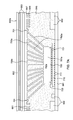
- FIG. 9A is a partial cross-sectional elevational view of one embodiment of a vertically-oriented, immersion-cooled electronic subsystem, in accordance with an aspect of the present invention.
- FIG. 9B is a partial enlargement of the interleaved, liquid-cooled vapor condenser and heat spreader structure of FIG. 9A , in accordance with an aspect of the present invention.
- FIG. 10A is a partial cross-sectional elevational view of another embodiment of an immersion-cooled electronic subsystem, in accordance with an aspect of the present invention.
- FIG. 10B is a partial cross-sectional elevational view of the immersion-cooled electronic subsystem of FIG. 10A , taken along line 10 X- 10 X thereof, and illustrating one embodiment of an interleaved pin fin pattern, in accordance with an aspect of the present invention
- FIG. 10C is a partial cross-sectional elevational view of the immersion-cooled electronic subsystem of FIG. 10A , taken along line 10 X- 10 X thereof, and illustrating another embodiment of an interleaved pin fin pattern, in accordance with an aspect of the present invention.
- FIG. 10D is a partial cross-sectional elevational view of the immersion-cooled electronic subsystem of FIG. 10A , taken along line 10 X- 10 X thereof, and illustrating a further embodiment of an interleaved pin fin pattern, in accordance with an aspect of the present invention.
- an electronics rack may comprise one or more electronic subsystems, each having one or more heat generating components disposed therein requiring cooling.
- Electronic subsystem refers to any housing, blade, book, drawer, node, compartment, board, etc., having multiple heat generating electronic components disposed therein or thereon.
- Each electronic subsystem of an electronics rack may be movable or fixed relative to the electronics rack, with the rack-mounted electronic drawers of a rack unit and blades of a blade center system being two examples of subsystems of an electronics rack to be cooled.
- electronic subsystem refers to an electronic system which comprises multiple different types of electronic components, and may be, in one example, a server unit.
- Electronic component refers to any heat generating electronic component of, for example, a computer system or other electronics unit requiring cooling.
- an electronic component may comprise one or more integrated circuit dies and/or other electronic devices to be cooled, including one or more processor dies, memory dies and memory support dies.
- the electronic component may comprise one or more bare dies or one or more packaged dies disposed on a common carrier.
- liquid-cooled cold plate and “liquid-cooled base plate” each refer to any conventional thermally conductive structure having a plurality of channels or passageways formed therein for flowing of liquid-coolant therethrough.
- a “liquid-to-liquid heat exchanger” may comprise, for example, two or more coolant flow paths, formed of thermally conductive tubing (such as copper or other tubing) in thermal or mechanical contact with each other. Size, configuration and construction of the liquid-to-liquid heat exchanger can vary without departing from the scope of the invention disclosed herein.
- “data center” refers to a computer installation containing one or more electronics racks to be cooled. As a specific example, a data center may include one or more rows of rack-mounted computing units, such as server units.
- facility coolant and system coolant is water.
- the concepts disclosed herein are readily adapted to use with other types of coolant on the facility side and/or on the system side.
- these coolants may comprise a brine, a dielectric liquid, a fluorocarbon liquid, a liquid metal, or other similar coolant, or refrigerant, while still maintaining the advantages and unique features of the present invention.
- FIG. 1 in a raised floor layout of an air-cooled computer installation 100 typical in the prior art, multiple electronics racks 110 are disposed in one or more rows.
- a computer installation such as depicted in FIG. 1 may house several hundred, or even several thousand microprocessors.
- chilled air enters the computer room via floor vents from a supply air plenum 145 defined between the raised floor 140 and a base or sub-floor 165 of the room. Cooled air is taken in through louvered covers at air inlet sides 120 of the electronics racks and expelled through the back (i.e., air outlet sides 130 ) of the electronics racks.
- Each electronics rack 110 may have one or more air-moving devices (e.g., fans or blowers) to provide forced inlet-to-outlet air flow to cool the electronic components within the drawer(s) of the rack.
- the supply air plenum 145 provides conditioned and cooled air to the air-inlet sides of the electronics racks via perforated floor tiles 160 disposed in a “cold” aisle of the computer installation.
- the conditioned and cooled air is supplied to plenum 145 by one or more air conditioning units 150 , also disposed within the computer installation 100 . Room air is taken into each air conditioning unit 150 near an upper portion thereof. This room air comprises in part exhausted air from the “hot” aisles of the computer installation defined by opposing air outlet sides 130 of the electronics racks 110 .
- FIG. 2 depicts one embodiment of a liquid-cooled electronics rack 200 , which may comprise a cooling apparatus such as described herein below.
- liquid-cooled electronics rack 200 comprises a plurality of electronic subsystems 210 , which may be processor or server nodes (in one embodiment).
- a bulk power assembly 220 is disposed at an upper portion of liquid-cooled electronics rack 200 , and two modular cooling units (MCUs) 230 are positioned in a lower portion of the liquid-cooled electronics rack for providing system coolant to the electronic subsystems.
- the system coolant is assumed to be water or an aqueous-based solution, by way of example only.
- the cooling apparatus includes a system coolant supply manifold 231 , a system coolant return manifold 232 , and manifold-to-node fluid connect hoses 233 coupling system coolant supply manifold 231 to electronic subsystems 210 (for example, to cold plates or liquid-cooled vapor condensers (not shown) disposed within the subsystems) and node-to-manifold fluid connect hoses 234 coupling the individual electronic subsystems 210 to system coolant return manifold 232 .
- Each MCU 230 is in fluid communication with system coolant supply manifold 231 via a respective system coolant supply hose 235 , and each MCU 230 is in fluid communication with system coolant return manifold 232 via a respective system coolant return hose 236 .
- Heat load of the electronic subsystems is transferred from the system coolant to cooler facility coolant within the MCUs 230 provided via facility coolant supply line 240 and facility coolant return line 241 disposed, in the illustrated embodiment, in the space between raised floor 145 and base floor 165 .
- FIG. 3 schematically illustrates one cooling approach using the cooling apparatus of FIG. 2 , wherein a liquid-cooled cold plate 300 is shown coupled to an electronic component 301 of an electronic subsystem 210 within the liquid-cooled electronics rack 200 .
- Heat is removed from electronic component 301 via system coolant circulating via pump 320 through liquid-cooled cold plate 300 within the system coolant loop defined, in part, by liquid-to-liquid heat exchanger 321 of modular cooling unit 230 , hoses 235 , 236 and cold plate 300 .
- the system coolant loop and modular cooling unit are designed to provide coolant of a controlled temperature and pressure, as well as controlled chemistry and cleanliness to the electronic subsystems.
- the system coolant is physically separate from the less controlled facility coolant in lines 240 , 241 , to which heat is ultimately transferred.
- FIG. 4 depicts one detailed embodiment of a modular cooling unit 230 .
- modular cooling unit 230 includes a facility coolant loop, wherein building chilled, facility coolant is provided (via lines 240 , 241 ) and passed through a control valve 420 driven by a motor 425 .
- Valve 420 determines an amount of facility coolant to be passed through heat exchanger 321 , with a portion of the facility coolant possibly being returned directly via a bypass orifice 435 .
- the modular cooling unit further includes a system coolant loop with a reservoir tank 440 from which system coolant is pumped, either by pump 450 or pump 451 , into liquid-to-liquid heat exchanger 321 for conditioning and output thereof, as cooled system coolant to the electronics rack to be cooled.
- Each modular cooling unit is coupled to the system supply manifold and system return manifold of the liquid-cooled electronics rack via the system coolant supply hose 235 and system coolant return hose 236 , respectively.
- FIG. 5 depicts another cooling approach, illustrating one embodiment of an electronic subsystem 210 component layout wherein one or more air moving devices 511 provide forced air flow 515 in normal operating mode to cool multiple electronic components 512 within electronic subsystem 210 . Cool air is taken in through a front 531 and exhausted out a back 533 of the drawer.
- the multiple components to be cooled include multiple processor modules to which liquid-cooled cold plates 520 are coupled, as well as multiple arrays of memory modules 530 (e.g., dual in-line memory modules (DIMMs)) and multiple rows of memory support modules 532 (e.g., DIMM control modules) to which air-cooled heat sinks may be coupled.
- DIMMs dual in-line memory modules
- memory modules 530 and the memory support modules 532 are partially arrayed near front 531 of electronic subsystem 210 , and partially arrayed near back 533 of electronic subsystem 210 . Also, in the embodiment of FIG. 5 , memory modules 530 and the memory support modules 532 are cooled by air flow 515 across the electronics subsystem.
- the illustrated cooling apparatus further includes multiple coolant-carrying tubes connected to and in fluid communication with liquid-cooled cold plates 520 .
- the coolant-carrying tubes comprise sets of coolant-carrying tubes, with each set including (for example) a coolant supply tube 540 , a bridge tube 541 and a coolant return tube 542 .
- each set of tubes provides liquid-coolant to a series-connected pair of cold plates 520 (coupled to a pair of processor modules). Coolant flows into a first cold plate of each pair via the coolant supply tube 540 and from the first cold plate to a second cold plate of the pair via bridge tube or line 541 , which may or may not be thermally conductive. From the second cold plate of the pair, coolant is returned through the respective coolant return tube 542 .
- direct immersion-cooling of electronic components of an electronic subsystem of the rack within dielectric fluid may be employed.
- dielectric fluid e.g., a liquid dielectric coolant
- Such an immersion-cooling approach advantageously avoids forced air cooling and enables total liquid-cooling of the electronics rack within a data center.
- indirect liquid-cooling such as described above in connection with FIGS. 3 and 5 , has certain advantages due to the low cost and wide availability of water as a coolant, as well as its superior thermal and hydraulic properties, where possible and viable, the use of dielectric fluid immersion-cooling may offer several unique benefits.
- the use of a dielectric fluid that condenses at a temperature above typical outdoor ambient air temperature would enable data center cooling architectures which do not require energy intensive refrigeration chillers.
- Yet other practical advantages, such as the ability to ship a coolant filled electronic subsystem may offer benefit over water-cooled approaches such as depicted in FIGS. 3 and 5 , which require shipping dry and the use of a fill and drain protocol to insure against freeze damage during transport.
- the use of liquid immersion-cooling may, in certain cases, allow for greater compaction of electronic components at the electronic subsystem level and/or electronic rack level since conductive cooling structures might be eliminated.
- dielectric fluid immersion-cooling of one or more electronic subsystems of an electronics rack may offer significant energy efficiency and higher performance cooling benefits, compared with currently available hybrid air and indirect water (only) cooled systems.
- the dielectric fluid may comprise any one of a variety of commercially available dielectric coolants.
- any of the NovecTM fluids manufactured by 3M Corporation e.g., FC-72, FC-86, HFE-7000, and HFE-7200
- a refrigerant such as R-134a or R-245fa may be employed if desired.
- FIG. 6A is a schematic of one embodiment of a liquid-cooled electronics rack, generally denoted 600 , employing immersion-cooling of electronic subsystems, in accordance with an aspect of the present invention.
- liquid-cooled electronics rack 600 includes an electronics rack 601 containing a plurality of electronic subsystems 610 disposed, in the illustrated embodiment, horizontally so as to be stacked within the rack.
- each electronic subsystem 610 may be a server unit of a rack-mounted plurality of server units.
- each electronic subsystem includes multiple electronic components to be cooled, which in one embodiment, comprise multiple different types of electronic components having different heights and/or shapes within the electronic subsystem.
- the cooling apparatus is shown to include one or more modular cooling units (MCU) 620 disposed, by way of example, in a lower portion of electronics rack 601 .
- Each modular cooling unit 620 may be similar to the modular cooling unit depicted in FIG. 4 , and described above.
- the modular cooling unit includes, for example, a liquid-to-liquid heat exchanger for extracting heat from coolant flowing through a system coolant loop 630 of the cooling apparatus and dissipating heat within a facility coolant loop 619 , comprising a facility coolant supply line 621 and a facility coolant return line 622 .
- facility coolant supply and return lines 621 , 622 couple modular cooling unit 620 to a data center facility coolant supply and return (not shown).
- Modular cooling unit 620 further includes an appropriately sized reservoir, pump and optional filter for moving liquid-coolant under pressure through system coolant loop 630 .
- system coolant loop 630 includes a coolant supply manifold 631 and a coolant return manifold 632 , which are coupled to modular cooling unit 620 via, for example, flexible hoses.
- the flexible hoses allow the supply and return manifolds to be mounted within, for example, a door of the electronics rack hingedly mounted to the front or back of the electronics rack.
- coolant supply manifold 631 and coolant return manifold 632 each comprise an elongated rigid tube vertically mounted to the electronics rack 601 or to a door of the electronics rack.
- coolant supply manifold 631 and coolant return manifold 632 are in fluid communication with respective coolant inlets 635 and coolant outlets 636 of individual sealed housings 640 containing the electronic subsystems 610 .
- Fluid communication between the manifolds and the sealed housings is established, for example, via appropriately sized, flexible hoses 633 , 634 .
- each coolant inlet 635 and coolant outlet 636 of a sealed housing is coupled to a respective liquid-cooled vapor condenser 650 disposed within the sealed housing 640 .
- Heat removed from the electronic subsystem 610 via the respective liquid-cooled vapor condenser 650 is transferred from the system coolant via the coolant outlet manifold 632 and modular cooling unit 620 to facility coolant loop 619 .
- coolant passing through system coolant loop 630 , and hence, coolant passing through the respective liquid-cooled vapor condensers 650 is water.
- fluidic coupling between the electronic subsystems and coolant manifolds, as well as between the manifolds and the modular cooling unit(s) can be established using suitable hoses, hose barb fittings and quick disconnect couplers.
- the vertically-oriented coolant supply and return manifolds 631 , 632 each include ports which facilitate fluid connection of the respective coolant inlets and outlets 635 , 636 of the housings (containing the electronic subsystems) to the manifolds via the flexible hoses 633 , 634 .
- Respective quick connect couplings may be employed to couple the flexible hoses to the coolant inlets and coolant outlets of the sealed housings to allow for, for example, removal of a housing and electronic subsystem from the electronics rack.
- the quick connect couplings may be any one of various types of commercial available couplings, such as those available from Colder Products Co. of St. Paul, Minn., USA or Parker Hannifin of Cleveland, Ohio, USA.
- One or more hermetically sealed electrical connectors 648 may also be provided in each sealed housing 640 , for example, at a back surface thereof, for docking into a corresponding electrical plane of the electronics rack in order to provide electrical and network connections 649 to the electronic subsystem disposed within the sealed housing when the electronic subsystem is operatively positioned within the sealed housing and the sealed housing is operatively positioned within the electronics rack.
- electronic subsystem 610 comprises a plurality of electronic components 642 , 643 of different height and type on a substrate 641 , and is shown within sealed housing 640 with the plurality of electronic components 642 , 643 immersed within a dielectric fluid 645 .
- Sealed housing 640 is configured to at least partially surround and form a sealed compartment about the electronic subsystem with the plurality of electronic components 642 , 643 disposed within the sealed compartment.
- dielectric fluid 645 pools in the liquid state at the bottom of the sealed compartment and is of sufficient volume to submerge the electronic components 642 , 643 .
- the electronic components 642 , 643 dissipate varying amounts of power, which cause the dielectric fluid to boil, releasing a dielectric fluid vapor, which rises to the upper portion of the sealed compartment of the housing.
- the upper portion of sealed housing 640 is shown in FIG. 6B to include liquid-cooled vapor condenser 650 .
- Liquid-cooled vapor condenser 650 is a thermally conductive structure which includes a liquid-cooled base plate 652 , and a plurality of thermally conductive condenser fins 651 extending therefrom in the upper portion of the sealed compartment.
- a plenum structure 654 comprises part of liquid-cooled base plate 652 , and facilitates passage of system coolant through one or more channels 653 ( FIG. 6B ) in the liquid-cooled base plate 652 .
- the dielectric fluid vapor contacts the cool surfaces of the thermally conductive condenser fins and condenses back to liquid phase, dropping downwards towards the bottom of the sealed compartment.
- System coolant supplied to the coolant inlet of the housing passes through the liquid-cooled base plate of the liquid-cooled vapor condenser and cools the solid material of the condenser such that condenser fin surfaces that are exposed within the sealed compartment to the dielectric fluid vapor (or the dielectric fluid itself) are well below saturation temperature of the vapor.
- vapor in contact with the cool condenser fin surfaces will reject heat to these surfaces and condense back to liquid form.
- the condensed liquid may be close in temperature to the vapor temperature or could be sub-cooled to a much lower temperature.
- the liquid-cooled vapor condenser of the cooling apparatus presented comprises a first set of thermally conductive condenser fins 655 and a second set of thermally conductive condenser fins 651 , wherein the second set of thermally conductive condenser fins 651 are of shorter length than the first set of thermally conductive condenser fins 655 .
- the first set of thermally conductive condenser fins 655 extend into dielectric fluid 645 , and are interleaved (or interdigitated) with multiple fluid-boiling fins 660 extending from a fluid-boiling base 661 of a heat spreader 662 coupled to one or more electronic components 643 of the electronic subsystem.
- the second set of thermally conductive condenser fins 651 comprise a plurality of pin fins of any desired configuration
- the first set of thermally conductive condenser fins 655 comprise a plurality of plate fins, which may have a variety of transverse, cross-sectional perimeter configurations.
- the first set of thermally conductive condenser fins 655 are illustrated in certain of the figures as rectangular plates depending from liquid-cooled base plate 652 .
- the concepts presented are readily applicable to a variety of different pin fin configurations.
- the condenser fins 651 might have a square, rectangular, circular, trapezoidal, triangular, parallelogram, part rectangular part curve, etc. transverse cross-sectional perimeter along at least a portion of their length.
- the thermally conductive plate fins 655 comprise a first main surface and a second main surface, at least one of which are in spaced, opposing relation to respective fluid-boiling fins 660 , which in one example, are fluid-boiling plate fins.
- heat spreader 662 is coupled to at least one electronic component 643 to be cooled, and facilitates transfer of heat from the at least one electronic component 643 to the multiple thermally conductive condenser plate fins 655 of the liquid-cooled vapor condenser.
- electronic component 643 may comprise a high heat dissipating component, such as a processor module or multi-chip module of the electronic subsystem.
- interleaved condenser plate fins and fluid-boiling plate fins illustrated in FIGS. 6B & 6C allow for localized cooling and condensing of dielectric fluid vapor in the region of the interleaved fins, which reduces dielectric fluid vapor 646 accumulation within the upper portion of the sealed compartment.
- thermally conductive plate fins 655 are each in opposing relation with one or more different fluid-boiling plate fins 660 of heat spreader 662 .
- plate fins 655 depend downwards into dielectric fluid 645 adjacent to the respective fluid-boiling plate fins.
- dielectric fluid vapor bubbles generated by, for example, boiling of dielectric fluid contacting one or more fluid-boiling surfaces will be cooled and condensed back into liquid state in the vicinity of the heat spreader, thereby facilitating enhanced cooling of the electronic subsystem.
- some dielectric fluid vapor 646 will rise to an upper portion of the housing, along with any non-condensable gas (such as air) 647 coming out of solution from the dielectric fluid.
- Non-condensable gas can reside in solution within the dielectric fluid, but once coming out of solution through the boiling process, cannot be returned to solution through the condensation process.
- interwoven heat source and heat sink surfaces immersed within a dielectric fluid which results in enhanced cooling of, for example, higher power components of an immersion-cooled electronic subsystem.
- these higher power components may comprise processor modules or chips, with condenser fins being provided extending into the spaces between adjacent fluid-boiling fins of the heat spreader coupled to the higher power components.
- the resultant localized cooling and condensing of dielectric fluid vapor generated by the one or more electronic components reduces the extent of vapor accumulation within the sealed housing, thereby facilitating enhanced cooling of the components of the electronic subsystem.
- Lower power electronic components such as electronic components 642 in FIG.
- FIG. 6B are cooled employing pool boiling of dielectric fluid, without the aid of special structures such as illustrated in FIG. 6C .
- boiling occurs from the surfaces of the heat spreader in physical contact with the dielectric fluid within which the electronic components are immersed. These surfaces are one example of fluid-boiling surfaces, as the phrase is used herein.
- FIGS. 7A-10D depict alternate embodiments of the interwoven heat source and heat sink structures of an immersion-cooled electronic subsystem, such as depicted in FIGS. 6A-6C and described above. Unless otherwise indicated, these alternate embodiments of a cooling apparatus are similar or identical to the cooling apparatus described above in connection with FIGS. 6A-6C .
- FIG. 7A illustrates an alternate implementation of an immersion-cooled electronic subsystem of a liquid-cooled electronics rack, in accordance with an aspect of the present invention.
- the liquid-cooled vapor condenser 650 a further includes a condenser fin base support 700 a , which is secured to the liquid-cooled base plate 652 via attachment mechanisms 701 . Attaching to the liquid-cooled base plate can be achieved in several way using, for example, tools inserted from the side or using bosses in the base plate to allow access to the attachment mechanisms from the top of the condenser.
- heat spreader 762 a may be attached to one or more electronic components of the electronic subsystem using a permanent joint material, such as solder or epoxy.
- Multiple thermally conductive condenser fins 755 a extend from condenser fin base support 700 a and are angled to extend in an at least partially converging manner from condenser fin base support 700 a .
- multiple fluid-boiling fins 760 a of heat spreader 762 a extend in an at least partially diverging manner from fluid-boiling base 761 a .
- the volume occupied by the dielectric fluid between the interleaved thermally conductive condenser fins and fluid-boiling fins has a diverging shape upwards from the heat spreader, with the smaller volume being closer to the fluid-boiling base of the heat spreader, and the larger volume closer to the condenser fin base support of the liquid-cooled vapor condenser.
- dielectric fluid in liquid state pools in the region of smaller volume over fluid-boiling base 761 a of heat spreader 762 a , and dielectric fluid vapor rises and accumulates in the region of larger volume adjacent to condenser fin base support 700 a of liquid-cooled vapor condenser 650 a.
- the length of the interdigitated fins in this design will be longer than the fin lengths illustrated for the design of FIGS. 6A-6C . That is, the interleaved converging and diverging fin characteristic of the condenser and boiling fins means fins of greater heat transfer surface area can be used for both the fluid-boiling surfaces and the vapor condensing surfaces.
- the interleaved thermally conductive condenser fins of the vapor condenser and fluid-boiling fins of the heat spreader may be manufactured separately as a subassembly that is first attached to either the heat source (i.e., the one or more electronic components) or the heat sink (i.e., liquid-cooled vapor condenser), and then attached to the other of the heat source and heat sink.
- the fluid-boiling fins and thermally conductive condenser fins may be structurally interleaved (i.e., interdigitated), they are spaced from and able to move relative to each other, which facilitates attachment of the interleaved structures to the different heat source and heat sink surfaces.
- heat spreader 762 a is attached to an integrated circuit chip 720 via, for example, a solder or epoxy interface (not shown), and the condenser fin base support 700 a is attached to the larger liquid-cooled base plate 652 via attachment mechanisms 701 and, for example, a thermal interface material to improve thermal contact between the two mating surfaces.
- Integrated circuit chip 720 is electrically connected to wiring of a substrate 710 via, for example, solder bump connections 721 , and an underfill material 723 surrounds solder bump connections 721 of integrated circuit chip 720 and substrate 710 .
- Substrate 710 is itself electrically connected to, for example, an electronic subsystem substrate 641 via a second set of solder bump connections 711 . Also shown in FIG.
- liquid-cooled vapor condenser 650 a resides in the upper portion of the sealed compartment, and has a footprint which extends across and fills the upper portion thereof. In one specific implementation, the vapor condenser has a footprint approximately equal to the footprint of the electronic subsystem within the sealed compartment.
- any non-condensable gas 647 is likely to accumulate at the highest level of the sealed compartment, that is, on either side of the condenser fin base support, which will yield improved performance of the interleaved condenser and heat spreader subassembly (since the non-condensable gases will accumulate elsewhere within the sealed compartment).
- the condenser fins extending into the dielectric fluid also locally sub-cool the fluid, yielding better boiling performance through a reduction in vapor bubble diameter at the boiling surfaces of structures 760 a and 761 a .
- layered coolant channels 653 within liquid-cooled base plate 652 in FIG. 7A are provided by way of example only. If desired, a single layer of coolant channels, or more than two layers, could be employed within the liquid-cooled base plate.
- the coolant channels could be, for example, simple cylindrical tubes or openings in the base plate, or could have one or more fin structures extending therein for an enhanced heat transfer area between the base plate and system coolant flowing through the base plate. In this regard, see the embodiment of FIG. 8 , which is described below.
- FIGS. 7B & 7C a variation of the immersion-cooled electronic subsystem of FIG. 7A is illustrated.
- This embodiment is identical to the immersion-cooled electronic subsystem of FIG. 7A , with the exception being the addition of a porous filler material 730 suspended within the sealed compartment between, for example, one or more electronic components 642 and the thermally conductive condenser fins 651 of the liquid-cooled vapor condenser 650 a .
- this suspended porous filler material is provided, in one embodiment, to reduce an amount of dielectric fluid required within the sealed compartment to achieve full immersion of the electronic subsystem's plurality of electronic components and immersion of the interleaved fins discussed above.
- porous filter material 730 resides at least partially, if not fully, below the dielectric liquid level within the sealed compartment in order to displace the dielectric fluid, and thereby reduce the amount of dielectric fluid needed for immersion-cooling of electronic components of the electronic subsystem (as well as the interleaved condenser and boiling fin subassembly).
- porous filler material 730 is a low-weight polymeric filler material having a lower cost and lower weight than the dielectric fluid. This lighter weight and lower cost filler material also serves to reduce the weight and cost of the cooling apparatus.
- the filler material may, in one embodiment, include a plurality of spherical or other shaped, sealed air pockets (or volumes), which would serve to further reduce the weight of the filler material and reduce the amount of filler material required to manufacture the immersion-cooled electronic subsystem.
- One or more vertically-oriented cavities or channels 731 are provided through the filler material to allow for the rising of dielectric fluid vapor (or warm dielectric fluid) through the filler material, and the falling of a film or droplets of dielectric fluid condensate from the upper portion of the sealed compartment to the lower portion of the sealed compartment through the filler material.
- FIG. 7D illustrates another embodiment of an immersion-cooled electronic subsystem, such as described above in connection with FIGS. 6B-7A .
- the multiple thermally conductive condenser fins 755 b and multiple fluid-boiling fins 760 b (extending from fluid-boiling base 761 b ) of the liquid-cooled vapor condenser 650 a and heat spreader 762 b , respectively, are similar to the converging condenser fins and diverging fluid-boiling fins described above in FIG. 7A , but with roughly triangular-shaped, elongate cross-sections.
- the thermally conductive condenser fins may each comprise thermally conductive condenser plate fins with transverse cross-sectional perimeters which vary along at least a portion of the length thereof from condenser fin base support 700 b towards heat spreader 762 b .
- the diverging fluid-boiling fins 760 b of heat spreader 762 b may each be a fluid-boiling plate fin having a transverse cross-sectional perimeter which varies along at least a portion of a length thereof from the fluid-boiling base 761 b of the heat spreader towards the vapor condenser 650 a .
- the transverse cross-sectional perimeters of both the thermally conductive condenser fins and the fluid-boiling fins decrease along the length of the respective fins from their base outwards.
- This configuration of fins yields an optimal mass fin shape that performs better with respect to heat dissipation rate per unit fin mass compared to, for example, a plate fin having a rectangular cross-sectional shape that has a consistent transverse cross-sectional perimeter along its length.
- the illustrated fin shape also allows for greater fin material in regions of higher heat transfer coefficients in both the condenser and boiler regions, that is, at the respective fin bases.
- a heat spreader with fluid-boiling plate fins as described herein (having the illustrated cross-section) can be readily manufactured using commercial extrusion processes.
- the interleaved fin subassembly can be assembled (in one embodiment) by sliding the respective condenser and heat spreader structures in a direction, for example, perpendicular, to the page of the illustrated figure.
- the illustrated fluid-boiling and condenser fins can also be used in a non-diverging (i.e., non-diverging fluid-boiling fins) and non-converging (i.e., non-converging condenser fins) subassembly, such as the subassembly illustrated in FIG. 6C .
- FIG. 7E illustrates a further embodiment of an immersion-cooled electronic subsystem, in accordance with an aspect of the present invention.
- one or more of the condenser fins 755 c are made longer than one or more other condenser fins 755 c by, for example, providing one or more bends in the longer condenser fins.
- the longer condenser fins are illustrated to comprise two right-angle bends, forming zig-zag-shaped fins which are interleaved with corresponding zig-zag-shaped fluid-boiling fins 760 c of heat spreader 762 c .
- one or more fluid-boiling fins 760 c are shown to comprise a longer length than one or more other fluid-boiling fins 760 c of heat spreader 762 c .
- the zig-zag shapes of selected condenser fins and fluid-boiling fins results in the longer fin lengths, and thus, greater fin heat transfer surface areas compared with the straight condenser and fluid-boiling fins in the central region of the interleaved vapor condenser and heat spreader.
- the zig-zag-shaped fins can be manufactured using a low-cost stamping and folding process, as will be understood by one skilled in the art, and the interleaved fin subassembly can be achieved by sliding the fins relative to each other in a direction perpendicular to the illustrated drawing page.
- FIG. 7F illustrates an immersion-cooled electronic subsystem with a different type of interwoven heat spreader and heat sink (i.e., vapor condenser) structure, wherein fluid-boiling fins 760 d each comprise a primary fluid-boiling fin 763 d and a plurality of secondary fluid-boiling fins 764 d extending from the main surfaces thereof in opposing relation with a respective thermally conductive condenser fin 755 d .
- each thermally conductive condenser fin 755 d comprises a primary condenser fin 756 d having a first main surface and a second main surface from which a plurality of secondary condenser fins 757 d extend.
- the fins of the condenser and heat spreader can either overlap each other, or not.
- the use of multiple hierarchically-nested fins, such as depicted in FIG. 7F provides a greater heat transfer surface area within an available volume to accommodate the condenser and heat spreader fin subassembly.
- the subassembly of FIG. 7F can be manufactured separately and subsequently coupled to the liquid-cooled base plate and to the one or more electronic components to be cooled.
- FIG. 8 depicts a variation of the immersion-cooled electronic subsystem of FIG. 7F .
- heat pipes 801 , 811 are provided within the fluid-boiling and condenser fins 760 d , 755 d .
- heat pipes 801 , 811 are embedded within the fluid-boiling base 800 and condenser fin base support 810 , respectively.
- the heat pipes may exclusively be provided within either the heat spreader or within the vapor condenser structures.
- the use of heat pipes facilitates extraction of heat from a larger footprint of the heat spreader, and the rejection of this heat to a larger footprint of the vapor condenser, while enabling the actual heat sink and condenser fin subassembly to have a footprint that is much less than the heat generating and heat rejecting sides of the subassembly.
- the heat pipe concept could be employed with any of the interleaved fin subassemblies of the immersion-cooled electronic subsystems illustrated herein.
- DIMM card arrays 850 which are cooled by dielectric fluid 645 and the plurality of thermally conductive condenser fins 651 disposed above the DIMM card arrays.
- One or more higher-power processor chips 720 are illustrated in FIG. 8 coupled via respective substrates 710 to a common electronic subsystem substrate (or board) 641 .
- a common thermally conductive lid or cover 805 is provided over the one or more higher-power processor chips 720 .
- a heat spreader with the illustrated heat pipes and primary and secondary fluid-boiling fins is manufactured as a single unit, and brought down onto the electronic subsystem substrate in contact with the multi-chip module lid 805 , and then tightly attached to the substrate via multiple attachment mechanisms 802 through access openings 820 , which are sealed (not shown) after attachment of the attachment mechanisms 802 .
- a thermal interface material (not shown) may be placed between the fluid-boiling base 800 and the multi-chip module lid 805 .
- attachment mechanisms 812 on the upper side of the liquid-cooled base plate may be used to secure the condenser fin base support 810 to the base plate 652 . The process can be reversed if the condenser body is to be lifted off of the electronic subsystem board or substrate.
- FIG. 8 also illustrates certain internal surfaces of the embedded coolant channels 653 possessing fins 815 to enhance heat transfer surface area in the region of the interleaved vapor condenser and heat spreader subassembly, and thus provide a higher heat transfer coefficient over the higher-performing condenser heat sink region.
- the interleaved heat spreader and vapor condenser structure can be fabricated as a separate subassembly, the fins possess the ability to move relative to each other, which allows the attachment process to be more readily performed.
- the sealed housing described above in connection with FIGS. 6A-6C encapsulates both the electronic subsystem substrate and the vapor condenser, which would be inserted into the housing after they have been assembled relative to each other (in one embodiment).
- FIG. 9A is a partial schematic of one embodiment of a vertically-oriented, immersion-cooled electronic subsystem, generally denoted 900 , in accordance with an aspect of the present invention.
- multiple such electronic subsystems may be inserted vertically into a larger housing, such as an electronics rack (not shown).
- Liquid cooling for the liquid-cooled vapor condenser 950 may be provided as described above in connection with the liquid-cooled electronics rack embodiment of FIGS. 6A-6C .
- immersion-cooled electronic subsystem 900 includes a plurality of electronic components, 920 , 942 of different height and type on a substrate 941 .
- the substrate 941 is shown within a sealed housing 940 with the plurality of electronic components 920 , 942 immersed within a dielectric fluid 945 .
- Sealed housing 940 is configured to at least partially surround and form a sealed compartment about the electronic subsystem, with the plurality of electronic components 920 , 942 disposed within the sealed compartment.
- Electronic components 920 , 942 dissipate varying amounts of power, which causes the dielectric fluid to boil, releasing a dielectric fluid vapor, which rises towards the upper portion of the sealed compartment of the housing.
- electronic component 920 may comprise a high-power processor chip or multi-chip module which is electrically coupled via multiple solder bump connections 912 to a substrate 910 , itself coupled to electronic subsystem substrate 941 via multiple additional solder bump connections 911 .
- An underfill material 923 fills the gaps between substrate 910 and electronic component 920 .
- electronic component 920 is assumed to be a significantly higher heat-generating component compared with electronic component 942 of the electronic subsystem.
- a heat spreader 962 is provided comprising a fluid-boiling base 961 and a plurality of fluid-boiling fins 960 extending therefrom and sloping in an upwards direction.
- Facing heat spreader 962 is liquid-cooled vapor condenser 950 , which includes a first set of thermally conductive condenser fins 955 and a second set of thermally conductive condenser fins 951 .
- the thermally conductive condenser fins 955 are shown to be interleaved with the fluid-boiling fins 960 of heat spreader 962 , and to extend in a downwards-sloping manner from a liquid-cooled base plate 952 (comprising one or more coolant-carrying channels 953 ), towards heat spreader 962 .
- the provision of sloped fins provides a greater fin surface area, and the provision of sloped fins relative to the vertical orientation of the electronics subsystem facilitates an alignment of the fins with the natural recirculation pattern that would arise from the boiling and condensation processes within the sealed compartment.
- This is illustrated in FIG. 9B , where dielectric fluid condensate 970 flows downward along the sloped surfaces of condenser fins 955 , and dielectric vapor 971 rises upwards along the sloped surfaces of fluid-boiling fins 960 .
- the sloped fins could be designed to allow for the liquid-cooled vapor condenser to drop down towards the electronic subsystem substrate 941 , or extend down at an angle that is parallel to the plane of the heat spreader and condenser fins.
- FIGS. 10A-10D illustrate a variation on the immersion-cooled electronic subsystem of FIGS. 6A-6C .
- the condenser fins 1000 and the fluid-boiling fins 1010 are each pin fins that are, by way of example only, cylindrical pin fins.
- the pin fins could have a variety of different pin fin cross-sectional configurations.
- the condenser or fluid-boiling fins might have one or more of a rectangular, square, trapezoidal, triangular, parallelogram, part rectangular part curve, etc., transverse cross-sectional perimeter.
- the condenser and heat spreader pin fins can be arrayed in various layouts.
- FIGS. 10B-10D illustrate three such layout variations.
Abstract
Description
Claims (25)
Priority Applications (1)
| Application Number | Priority Date | Filing Date | Title |
|---|---|---|---|
| US12/825,776 US8345423B2 (en) | 2010-06-29 | 2010-06-29 | Interleaved, immersion-cooling apparatuses and methods for cooling electronic subsystems |
Applications Claiming Priority (1)
| Application Number | Priority Date | Filing Date | Title |
|---|---|---|---|
| US12/825,776 US8345423B2 (en) | 2010-06-29 | 2010-06-29 | Interleaved, immersion-cooling apparatuses and methods for cooling electronic subsystems |
Publications (2)
| Publication Number | Publication Date |
|---|---|
| US20110315343A1 US20110315343A1 (en) | 2011-12-29 |
| US8345423B2 true US8345423B2 (en) | 2013-01-01 |
Family
ID=45351407
Family Applications (1)
| Application Number | Title | Priority Date | Filing Date |
|---|---|---|---|
| US12/825,776 Active 2031-06-24 US8345423B2 (en) | 2010-06-29 | 2010-06-29 | Interleaved, immersion-cooling apparatuses and methods for cooling electronic subsystems |
Country Status (1)
| Country | Link |
|---|---|
| US (1) | US8345423B2 (en) |
Cited By (27)
| Publication number | Priority date | Publication date | Assignee | Title |
|---|---|---|---|---|
| US20140071627A1 (en) * | 2012-09-13 | 2014-03-13 | International Business Machines Corporation | Coolant drip facilitating partial immersion-cooling of electronic components |
| US20140071626A1 (en) * | 2012-09-13 | 2014-03-13 | International Business Machines Corporation | Vapor condenser with three-dimensional folded structure |
| US20150109735A1 (en) * | 2013-10-21 | 2015-04-23 | International Business Machines Corporation | Pump-enhanced, immersion-cooling of electronic component(s) |
| US20170290205A1 (en) * | 2016-04-04 | 2017-10-05 | Hamilton Sundstrand Corporation | Immersion cooling systems and methods |
| US9904811B2 (en) * | 2016-04-27 | 2018-02-27 | International Business Machines Corporation | Tamper-proof electronic packages with two-phase dielectric fluid |
| US10169967B1 (en) | 2016-02-25 | 2019-01-01 | International Business Machines Corporation | Multi-layer stack with embedded tamper-detect protection |
| US10172232B2 (en) | 2015-12-18 | 2019-01-01 | International Business Machines Corporation | Tamper-respondent assemblies with enclosure-to-board protection |
| US10177102B2 (en) | 2016-05-13 | 2019-01-08 | International Business Machines Corporation | Tamper-proof electronic packages with stressed glass component substrate(s) |
| US20190057180A1 (en) * | 2017-08-18 | 2019-02-21 | International Business Machines Corporation | System and method for design optimization using augmented reality |
| US10251288B2 (en) | 2015-12-01 | 2019-04-02 | International Business Machines Corporation | Tamper-respondent assembly with vent structure |
| US10257924B2 (en) | 2016-05-13 | 2019-04-09 | International Business Machines Corporation | Tamper-proof electronic packages formed with stressed glass |
| US10306753B1 (en) | 2018-02-22 | 2019-05-28 | International Business Machines Corporation | Enclosure-to-board interface with tamper-detect circuit(s) |
| US10378924B2 (en) | 2015-09-25 | 2019-08-13 | International Business Machines Corporation | Circuit boards and electronic packages with embedded tamper-respondent sensor |
| US10548239B1 (en) | 2018-10-23 | 2020-01-28 | Google Llc | Cooling electronic devices in a data center |
| US10548240B1 (en) | 2019-01-11 | 2020-01-28 | Google Llc | Cooling electronic devices in a data center |
| US10645847B2 (en) | 2018-04-20 | 2020-05-05 | Google Llc | Cooling electronic devices in a data center |
| US10667389B2 (en) | 2016-09-26 | 2020-05-26 | International Business Machines Corporation | Vented tamper-respondent assemblies |
| US10681846B2 (en) | 2018-04-19 | 2020-06-09 | Google Llc | Cooling electronic devices in a data center |
| US10685146B2 (en) | 2015-09-25 | 2020-06-16 | International Business Machines Corporation | Overlapping, discrete tamper-respondent sensors |
| US20200194339A1 (en) * | 2018-06-14 | 2020-06-18 | International Business Machines Corporation | Self-contained liquid cooled semiconductor packaging |
| US10966352B2 (en) | 2018-09-24 | 2021-03-30 | Google Llc | Cooling electronic devices in a data center |
| US11076509B2 (en) | 2017-01-24 | 2021-07-27 | The Research Foundation for the State University | Control systems and prediction methods for it cooling performance in containment |
| US11122682B2 (en) | 2018-04-04 | 2021-09-14 | International Business Machines Corporation | Tamper-respondent sensors with liquid crystal polymer layers |
| US11211538B1 (en) | 2020-12-23 | 2021-12-28 | Joseph L. Pikulski | Thermal management system for electrically-powered devices |
| US20220004234A1 (en) * | 2018-10-10 | 2022-01-06 | Zhengzhou Yunhai Information Technology Co., Ltd. | Siphon-based heat sink for server |
| US11716806B1 (en) | 2021-11-18 | 2023-08-01 | Motorola Mobility Llc | Processor heat dissipation in a stacked PCB configuration |
| US11758700B1 (en) * | 2021-06-16 | 2023-09-12 | Smart Wires Inc. | Indirect impingement liquid cooling for static synchronous series compensator systems |
Families Citing this family (24)
| Publication number | Priority date | Publication date | Assignee | Title |
|---|---|---|---|---|
| US8959941B2 (en) | 2011-07-21 | 2015-02-24 | International Business Machines Corporation | Data center cooling with an air-side economizer and liquid-cooled electronics rack(s) |
| US8955347B2 (en) | 2011-07-21 | 2015-02-17 | International Business Machines Corporation | Air-side economizer facilitating liquid-based cooling of an electronics rack |
| US20130091866A1 (en) | 2011-10-12 | 2013-04-18 | International Business Machines Corporation | Thermoelectric-enhanced, vapor-condenser facilitating immersion-cooling of electronic component(s) |
| US9273906B2 (en) | 2012-06-14 | 2016-03-01 | International Business Machines Corporation | Modular pumping unit(s) facilitating cooling of electronic system(s) |
| US9110476B2 (en) | 2012-06-20 | 2015-08-18 | International Business Machines Corporation | Controlled cooling of an electronic system based on projected conditions |
| US9879926B2 (en) | 2012-06-20 | 2018-01-30 | International Business Machines Corporation | Controlled cooling of an electronic system for reduced energy consumption |
| US8934250B2 (en) | 2012-09-26 | 2015-01-13 | International Business Machines Corporation | Immersion-cooling of selected electronic component(s) mounted to printed circuit board |
| US9313930B2 (en) | 2013-01-21 | 2016-04-12 | International Business Machines Corporation | Multi-level redundant cooling system for continuous cooling of an electronic system(s) |
| US9414520B2 (en) * | 2013-05-28 | 2016-08-09 | Hamilton Sundstrand Corporation | Immersion cooled motor controller |
| ITVI20130201A1 (en) * | 2013-07-31 | 2015-02-01 | Convett S R L | ALUMINUM RADIATOR WITH FINNED ELLIPTICAL TUBES. |
| CN104133538A (en) * | 2014-08-06 | 2014-11-05 | 浪潮电子信息产业股份有限公司 | Zone bit liquid cooling quick mounting modular server system |
| US10331182B2 (en) * | 2015-07-31 | 2019-06-25 | Hewlett Packard Enterprise Development Lp | Heat exchangers |
| US10600753B2 (en) | 2015-08-28 | 2020-03-24 | Texas Instruments Incorporated | Flip chip backside mechanical die grounding techniques |
| GB2549946A (en) | 2016-05-03 | 2017-11-08 | Bitfury Group Ltd | Immersion cooling |
| US10275002B2 (en) * | 2016-08-12 | 2019-04-30 | Prepared for Flight LLC | Enclosure for an electronic device |
| CN106455446B (en) * | 2016-10-28 | 2019-02-15 | 曙光信息产业(北京)有限公司 | The cooling device of heater element and the manufacturing method of cooling device |
| JP6790855B2 (en) * | 2017-01-18 | 2020-11-25 | 富士通株式会社 | Immersion cooling system, immersion cooling system and electronic device cooling method |
| JP2019160831A (en) * | 2018-03-07 | 2019-09-19 | 富士通株式会社 | Cooling plate and information processing apparatus |
| WO2020254917A1 (en) * | 2019-06-18 | 2020-12-24 | 3M Innovative Properties Company | Rack-mountable immersion cooling system |
| US20230071055A1 (en) | 2021-09-01 | 2023-03-09 | Quanta Computer Inc. | Nucleate boiling apparatus |
| US11608217B1 (en) | 2022-01-01 | 2023-03-21 | Liquidstack Holding B.V. | Automated closure for hermetically sealing an immersion cooling tank during a hot swap of equipment therein |
| GB2617193B (en) * | 2022-04-01 | 2024-04-10 | Iceotope Group Ltd | High thermal capacity heat sink |
| CN117545220A (en) * | 2022-08-02 | 2024-02-09 | 纬创资通股份有限公司 | Immersed cooling unit and electronic equipment |
| US20240085125A1 (en) * | 2022-09-14 | 2024-03-14 | Amulaire Thermal Technology, Inc. | Immersion-type heat dissipation structure having high density heat dissipation fins |
Citations (214)
| Publication number | Priority date | Publication date | Assignee | Title |
|---|---|---|---|---|
| US2125888A (en) | 1936-06-29 | 1938-08-09 | Liquid Carbonic Corp | Dry ice refrigerating apparatus |
| US2512545A (en) | 1948-06-11 | 1950-06-20 | Frederick E Hazard | Structure for and method of transfer, exchange, control regulation, and storage of heat and cold |
| US2548325A (en) | 1947-03-11 | 1951-04-10 | Maytag Co | Self-basting oven |
| US2643282A (en) | 1949-04-13 | 1953-06-23 | Albert D Greene | Electronic equipment cooling means |
| US2791888A (en) | 1955-09-22 | 1957-05-14 | Controlled Heat Transfer Corp | Heat exchange apparatus |
| US3109485A (en) | 1958-02-25 | 1963-11-05 | Fortier Andre | Heat exchanger |
| US3143592A (en) | 1961-11-14 | 1964-08-04 | Inland Electronics Products Co | Heat dissipating mounting structure for semiconductor devices |
| US3226941A (en) | 1963-10-31 | 1966-01-04 | Charles D Snelling | Klystron cooling system assembly |
| US3404730A (en) | 1966-12-02 | 1968-10-08 | Hughes Aircraft Co | Temperature control arrangement |
| US3476175A (en) | 1967-11-02 | 1969-11-04 | Bell Telephone Labor Inc | Vapor-phase cooling of electronic components |
| US3512582A (en) | 1968-07-15 | 1970-05-19 | Ibm | Immersion cooling system for modularly packaged components |
| US3578014A (en) | 1968-05-09 | 1971-05-11 | Jean Gachot | Pressure regulator for pressurized-fluid circuits |
| US3586101A (en) | 1969-12-22 | 1971-06-22 | Ibm | Cooling system for data processing equipment |
| US3600636A (en) | 1968-11-14 | 1971-08-17 | Danfoss As | Electrical apparatus comprising a power section and a control section with fluid cooling |
| US3609991A (en) | 1969-10-13 | 1971-10-05 | Ibm | Cooling system having thermally induced circulation |
| US3774677A (en) | 1971-02-26 | 1973-11-27 | Ibm | Cooling system providing spray type condensation |
| US3858909A (en) | 1973-08-07 | 1975-01-07 | Arthur S Friedman | Book indexing means |
| US4064300A (en) | 1975-07-16 | 1977-12-20 | Rolls-Royce Limited | Laminated materials |
| US4108242A (en) | 1971-07-23 | 1978-08-22 | Thermo Electron Corporation | Jet impingement heat exchanger |
| US4201195A (en) | 1978-10-25 | 1980-05-06 | Thermo Electron Corporation | Jet impingement solar collector |
| US4302793A (en) | 1979-11-30 | 1981-11-24 | Submergible Oil Systems, Inc. | Electronic cooling |
| US4430866A (en) | 1982-09-07 | 1984-02-14 | Emhart Industries, Inc. | Pressure control means for refrigeration systems of the energy conservation type |
| US4590538A (en) | 1982-11-18 | 1986-05-20 | Cray Research, Inc. | Immersion cooled high density electronic assembly |
| US4619316A (en) | 1984-04-27 | 1986-10-28 | Hitachi, Ltd. | Heat transfer apparatus |
| US4622946A (en) | 1985-05-16 | 1986-11-18 | Thermo Electron Corporation | Jet impingement/radiation gas-fired cooking range |
| US4649990A (en) * | 1985-05-06 | 1987-03-17 | Hitachi, Ltd. | Heat-conducting cooling module |
| US4694378A (en) | 1984-12-21 | 1987-09-15 | Hitachi, Ltd. | Apparatus for cooling integrated circuit chips |
| US4704658A (en) | 1985-04-30 | 1987-11-03 | Fujitsu Limited | Evaporation cooling module for semiconductor devices |
| US4741385A (en) | 1986-02-18 | 1988-05-03 | Iowa State University Research Foundation, Inc. | Gas jet impingement means and method |
| US4750086A (en) | 1985-12-11 | 1988-06-07 | Unisys Corporation | Apparatus for cooling integrated circuit chips with forced coolant jet |
| US4912600A (en) | 1988-09-07 | 1990-03-27 | Auburn Univ. Of The State Of Alabama | Integrated circuit packaging and cooling |
| US4928207A (en) | 1989-06-15 | 1990-05-22 | International Business Machines Corporation | Circuit module with direct liquid cooling by a coolant flowing between a heat producing component and the face of a piston |
| US4928206A (en) | 1988-11-23 | 1990-05-22 | Ncr Corporation | Foldable printed circuit board |
| US4962444A (en) | 1989-01-03 | 1990-10-09 | Sunstrand Corporation | Cold chassis for cooling electronic circuit components on an electronic board |
| US5021924A (en) | 1988-09-19 | 1991-06-04 | Hitachi, Ltd. | Semiconductor cooling device |
| US5057968A (en) | 1989-10-16 | 1991-10-15 | Lockheed Corporation | Cooling system for electronic modules |
| US5063476A (en) | 1989-12-05 | 1991-11-05 | Digital Equipment Corporation | Apparatus for controlled air-impingement module cooling |
| US5067047A (en) | 1990-05-11 | 1991-11-19 | At&T Bell Laboratories | Circuit pack with inboard jet cooling |
| US5126919A (en) | 1985-10-04 | 1992-06-30 | Fujitsu Limited | Cooling system for an electronic circuit device |
| US5168348A (en) | 1991-07-15 | 1992-12-01 | International Business Machines Corporation | Impingment cooled compliant heat sink |
| US5183104A (en) | 1989-06-16 | 1993-02-02 | Digital Equipment Corporation | Closed-cycle expansion-valve impingement cooling system |
| US5220804A (en) | 1991-12-09 | 1993-06-22 | Isothermal Systems Research, Inc | High heat flux evaporative spray cooling |
| US5270572A (en) | 1991-06-26 | 1993-12-14 | Hitachi, Ltd. | Liquid impingement cooling module for semiconductor devices |
| US5274530A (en) | 1992-05-29 | 1993-12-28 | Anderson William B | Module for protecting and cooling computer chip die mounted on a thin film substrate and a chassis for conduction cooling of such modules |
| US5297621A (en) * | 1989-07-13 | 1994-03-29 | American Electronic Analysis | Method and apparatus for maintaining electrically operating device temperatures |
| US5305184A (en) | 1992-12-16 | 1994-04-19 | Ibm Corporation | Method and apparatus for immersion cooling or an electronic board |
| US5349831A (en) | 1991-11-08 | 1994-09-27 | Hitachi, Ltd. | Apparatus for cooling heat generating members |
| US5390077A (en) * | 1994-07-14 | 1995-02-14 | At&T Global Information Solutions Company | Integrated circuit cooling device having internal baffle |
| US5406807A (en) | 1992-06-17 | 1995-04-18 | Hitachi, Ltd. | Apparatus for cooling semiconductor device and computer having the same |
| US5414592A (en) | 1993-03-26 | 1995-05-09 | Honeywell Inc. | Heat transforming arrangement for printed wiring boards |
| US5458185A (en) | 1991-11-15 | 1995-10-17 | Nec Corporation | Liquid coolant circulation control system for immersion cooling |
| US5467250A (en) | 1994-03-21 | 1995-11-14 | Hubbell Incorporated | Electrical cabinet with door-mounted heat exchanger |
| US5491363A (en) | 1992-02-10 | 1996-02-13 | Nec Corporation | Low boiling point liquid coolant cooling structure for electronic circuit package |
| US5675473A (en) | 1996-02-23 | 1997-10-07 | Motorola, Inc. | Apparatus and method for shielding an electronic module from electromagnetic radiation |
| US5687577A (en) | 1996-04-10 | 1997-11-18 | Motorola, Inc. | Apparatus and method for spray-cooling an electronic module |
| US5718117A (en) | 1996-04-10 | 1998-02-17 | Motorola, Inc. | Apparatus and method for spray-cooling an electronic module |
| US5780928A (en) * | 1994-03-07 | 1998-07-14 | Lsi Logic Corporation | Electronic system having fluid-filled and gas-filled thermal cooling of its semiconductor devices |
| US5785101A (en) | 1995-11-14 | 1998-07-28 | Timberjack Inc. | Tree harvesting and processing head |
| US5825621A (en) | 1997-06-12 | 1998-10-20 | Harris Corporation | Closed loop cooling housing for printed circuit card-mounted, sealed heat exchanger |
| US5829264A (en) | 1995-11-17 | 1998-11-03 | Sanyo Electric Co., Ltd. | Air conditioner having refrigerant pressure control means and driving control method therefor |
| US5854092A (en) | 1996-10-11 | 1998-12-29 | Motorola, Inc. | Method for spray-cooling a tunable semiconductor device |
| US5860602A (en) | 1996-12-06 | 1999-01-19 | Tilton; Charles L | Laminated array of pressure swirl atomizers |
| US5864466A (en) | 1994-07-19 | 1999-01-26 | Remsburg; Ralph | Thermosyphon-powered jet-impingement cooling device |
| US5880931A (en) | 1998-03-20 | 1999-03-09 | Tilton; Donald E. | Spray cooled circuit card cage |
| US5907473A (en) | 1997-04-04 | 1999-05-25 | Raytheon Company | Environmentally isolated enclosure for electronic components |
| US5943211A (en) | 1997-04-18 | 1999-08-24 | Raytheon Company | Heat spreader system for cooling heat generating components |
| US5959351A (en) | 1992-09-04 | 1999-09-28 | Hitachi, Ltd. | Liquid-cooled electronic device |
| US5963425A (en) | 1997-07-16 | 1999-10-05 | International Business Machines Corporation | Combined air and refrigeration cooling for computer systems |
| US5970731A (en) | 1997-11-21 | 1999-10-26 | International Business Machines Corporation | Modular refrigeration system |
| US6000908A (en) | 1996-11-05 | 1999-12-14 | General Electric Company | Cooling for double-wall structures |
| US6019167A (en) | 1997-12-19 | 2000-02-01 | Nortel Networks Corporation | Liquid immersion cooling apparatus for electronic systems operating in thermally uncontrolled environments |
| US6026565A (en) | 1997-06-12 | 2000-02-22 | Harris Corporation | Housing for diverse cooling configuration printed circuit cards |
| US6052284A (en) | 1996-08-06 | 2000-04-18 | Advantest Corporation | Printed circuit board with electronic devices mounted thereon |
| US6055157A (en) | 1998-04-06 | 2000-04-25 | Cray Research, Inc. | Large area, multi-device heat pipe for stacked MCM-based systems |
| US6173577B1 (en) | 1996-08-16 | 2001-01-16 | American Superconductor Corporation | Methods and apparatus for cooling systems for cryogenic power conversion electronics |
| US6193905B1 (en) | 1990-05-11 | 2001-02-27 | Fujitsu Limited | Immersion cooling coolant |
| US6205799B1 (en) | 1999-09-13 | 2001-03-27 | Hewlett-Packard Company | Spray cooling system |
| US6212895B1 (en) | 1999-11-19 | 2001-04-10 | Emmpak Foods Inc. | Machinery cooling system |
| US6243268B1 (en) | 1999-10-12 | 2001-06-05 | International Business Machines Corporation | Cooled IC chip modules with an insulated circuit board |
| US6320744B1 (en) | 1999-02-19 | 2001-11-20 | General Dynamics Information Systesm, Inc. | Data storage housing |
| US6366462B1 (en) | 2000-07-18 | 2002-04-02 | International Business Machines Corporation | Electronic module with integral refrigerant evaporator assembly and control system therefore |
| US6378605B1 (en) | 1999-12-02 | 2002-04-30 | Midwest Research Institute | Heat exchanger with transpired, highly porous fins |
| US6392891B1 (en) | 1999-07-02 | 2002-05-21 | Elta Electronics Industries Ltd. | Utilizing a convection cooled electronic circuit card for producing a conduction cooled electronic card module |
| US6393853B1 (en) | 2000-12-19 | 2002-05-28 | Nortel Networks Limited | Liquid cooling of removable electronic modules based on low pressure applying biasing mechanisms |
| US20020062945A1 (en) | 1997-09-30 | 2002-05-30 | Rainer Hocker | Wall part acted upon by an impingement flow |
| US6404640B1 (en) | 1998-08-11 | 2002-06-11 | Fujitsu Limited | Liquid-cooled electronic apparatus |
| US6431260B1 (en) | 2000-12-21 | 2002-08-13 | International Business Machines Corporation | Cavity plate and jet nozzle assemblies for use in cooling an electronic module, and methods of fabrication thereof |
| DE10112389A1 (en) | 2001-03-15 | 2002-10-02 | Martin Hess | Mobile radiotelephone service station for acting as a base station for mobile telephones, has protective cabinet sealed by cabinet doors and several stacked electronic modules |
| US6462941B1 (en) | 2000-06-30 | 2002-10-08 | Palm, Inc. | Method and apparatus for backlighting a handwriting input area for a portable computing device |
| JP2002374086A (en) | 2001-06-15 | 2002-12-26 | Hitachi Ltd | Cooling method of rack mounting information processor |
| US6519151B2 (en) | 2001-06-27 | 2003-02-11 | International Business Machines Corporation | Conic-sectioned plate and jet nozzle assembly for use in cooling an electronic module, and methods of fabrication thereof |
| US6536510B2 (en) | 2001-07-10 | 2003-03-25 | Thermal Corp. | Thermal bus for cabinets housing high power electronics equipment |
| US6571569B1 (en) | 2001-04-26 | 2003-06-03 | Rini Technologies, Inc. | Method and apparatus for high heat flux heat transfer |
| US6574104B2 (en) | 2001-10-05 | 2003-06-03 | Hewlett-Packard Development Company L.P. | Smart cooling of data centers |
| US6581388B2 (en) | 2001-11-27 | 2003-06-24 | Sun Microsystems, Inc. | Active temperature gradient reducer |
| US6616469B2 (en) | 2001-03-12 | 2003-09-09 | Tyco Electronics Logistics Ag | Electrical and fluid interconnect |
| US6644058B2 (en) | 2001-02-22 | 2003-11-11 | Hewlett-Packard Development Company, L.P. | Modular sprayjet cooling system |
| US6646879B2 (en) | 2001-05-16 | 2003-11-11 | Cray Inc. | Spray evaporative cooling system and method |
| US20030230401A1 (en) | 2002-06-18 | 2003-12-18 | Pfister Dennis M. | Distributed graphitic foam heat exchanger system |
| US20040008490A1 (en) | 2002-07-13 | 2004-01-15 | Kioan Cheon | Water cooling type soft cooling jacket for electronic device and buffer jacket using the same |
| US6708515B2 (en) | 2001-02-22 | 2004-03-23 | Hewlett-Packard Development Company, L.P. | Passive spray coolant pump |
| US20040057211A1 (en) | 2002-09-24 | 2004-03-25 | Yoshihiro Kondo | Electronic equipment |
| US6817196B2 (en) | 2001-02-22 | 2004-11-16 | Hewlett-Packard Development Company, L.P. | Spray cooling system with cooling regime detection |
| US6828675B2 (en) | 2001-09-26 | 2004-12-07 | Modine Manufacturing Company | Modular cooling system and thermal bus for high power electronics cabinets |
| US20050083655A1 (en) * | 2003-10-15 | 2005-04-21 | Visteon Global Technologies, Inc. | Dielectric thermal stack for the cooling of high power electronics |
| US6927980B2 (en) | 2003-06-27 | 2005-08-09 | Hitachi, Ltd. | Cooling structure for disk storage device |
| US20050207116A1 (en) | 2004-03-22 | 2005-09-22 | Yatskov Alexander I | Systems and methods for inter-cooling computer cabinets |
| US6953227B2 (en) * | 2002-12-05 | 2005-10-11 | Sun Microsystems, Inc. | High-power multi-device liquid cooling |
| US6955062B2 (en) | 2002-03-11 | 2005-10-18 | Isothermal Systems Research, Inc. | Spray cooling system for transverse thin-film evaporative spray cooling |
| US20050241802A1 (en) | 2004-04-29 | 2005-11-03 | Hewlett-Packard Development Company, L.P. | Liquid loop with flexible fan assembly |
| US20050244280A1 (en) | 2004-04-29 | 2005-11-03 | Hewlett-Packard Development Company, L.P. | Liquid loop with multiple pump assembly |
| US20050254214A1 (en) | 2004-05-11 | 2005-11-17 | Salmon Peter C | Cooling apparatus and method |
| US6973801B1 (en) | 2004-12-09 | 2005-12-13 | International Business Machines Corporation | Cooling system and method employing a closed loop coolant path and micro-scaled cooling structure within an electronics subsystem of an electronics rack |
| US6976528B1 (en) | 2003-02-18 | 2005-12-20 | Isothermal Systems Research, Inc. | Spray cooling system for extreme environments |
| US7011143B2 (en) | 2004-05-04 | 2006-03-14 | International Business Machines Corporation | Method and apparatus for cooling electronic components |
| US7012807B2 (en) | 2003-09-30 | 2006-03-14 | International Business Machines Corporation | Thermal dissipation assembly and fabrication method for electronics drawer of a multiple-drawer electronics rack |
| US7057893B2 (en) | 2002-03-11 | 2006-06-06 | Rittal Gmbh & Co. Kg | Cooling array |
| US20060126296A1 (en) | 2004-12-09 | 2006-06-15 | International Business Machines Corporation | Cooling apparatus and method for an electronics module employing an integrated heat exchange assembly |
| US7079393B2 (en) | 2004-11-16 | 2006-07-18 | International Business Machines Corporation | Fluidic cooling systems and methods for electronic components |
| US20060162365A1 (en) | 2004-10-26 | 2006-07-27 | Hoang Triem T | Cooling electronics via two-phase tangential jet impingement in a semi-toroidal channel |
| US7088585B2 (en) | 2003-12-03 | 2006-08-08 | International Business Machines Corporation | Cooling system and method employing at least two modular cooling units for ensuring cooling of multiple electronics subsystems |
| US20060180300A1 (en) | 2003-07-23 | 2006-08-17 | Lenehan Daniel J | Pump and fan control concepts in a cooling system |
| US7106590B2 (en) | 2003-12-03 | 2006-09-12 | International Business Machines Corporation | Cooling system and method employing multiple dedicated coolant conditioning units for cooling multiple electronics subsystems |
| US7104078B2 (en) | 2004-08-05 | 2006-09-12 | Isothermal Systems Research, Inc. | Spray cooling system for transverse thin-film evaporative spray cooling |
| US7134289B2 (en) | 2004-12-04 | 2006-11-14 | Hewlett-Packard Development Company, L.P. | Multi-state spray cooling system |
| US7143605B2 (en) | 2003-12-22 | 2006-12-05 | Hussman Corporation | Flat-tube evaporator with micro-distributor |
| US20070025081A1 (en) | 2005-07-28 | 2007-02-01 | Berlin Carl W | Electronic package and method of cooling electronics |
| US20070035937A1 (en) | 2005-08-11 | 2007-02-15 | International Business Machines Corporation | Method and apparatus for mounting a heat sink in thermal contact with an electronic component |
| US7187549B2 (en) | 2004-06-30 | 2007-03-06 | Teradyne, Inc. | Heat exchange apparatus with parallel flow |
| US7191954B2 (en) | 1998-10-02 | 2007-03-20 | Magarl, Llc | Method of mixing fluids using a valve |
| US7222502B2 (en) | 2004-02-13 | 2007-05-29 | Fujikoki Corporation | Expansion valve |
| US20070121295A1 (en) | 2005-11-30 | 2007-05-31 | International Business Machines Corporation | Hybrid liquid-air cooled module |
| US7233491B2 (en) | 2002-01-04 | 2007-06-19 | Intel Corporation | Frame-level thermal interface component for transfer of heat from an electronic component of a computer system |
| US7251139B2 (en) | 2003-11-26 | 2007-07-31 | Intel Corporation | Thermal management arrangement for standardized peripherals |
| US7252100B1 (en) | 2003-03-28 | 2007-08-07 | Emc Corporation | Systems and methods for processing a set of circuit boards |
| US20070183125A1 (en) | 2006-02-06 | 2007-08-09 | Isothermal Systems Research, Inc. | Narrow gap spray cooling in a globally cooled enclosure |
| US7258161B2 (en) | 2002-01-14 | 2007-08-21 | Emerson Network Power, Energy Systems, North America, Inc. | Cooling system for densely packed electronic components |
| US20070193300A1 (en) | 2006-02-21 | 2007-08-23 | Tilton Donald E | Two-phase liquid cooling system with active venting |
| US20070199204A1 (en) | 2003-08-25 | 2007-08-30 | Isothermal Systems Research, Inc. | Method of reducing fluid emissions from a global spray cooling system |
| US20070199340A1 (en) | 2003-08-25 | 2007-08-30 | Isothermal Systems Research, Inc. | Multi-chamber spray cooling system |
| US20070201210A1 (en) | 2006-02-16 | 2007-08-30 | Norman Chow | Liquid cooling loops for server applications |
| US7272005B2 (en) | 2005-11-30 | 2007-09-18 | International Business Machines Corporation | Multi-element heat exchange assemblies and methods of fabrication for a cooling system |
| US20070227710A1 (en) | 2006-04-03 | 2007-10-04 | Belady Christian L | Cooling system for electrical devices |
| US7285851B1 (en) | 2006-09-29 | 2007-10-23 | Teradyne, Inc. | Liquid immersion cooled multichip module |
| US7286356B2 (en) | 2004-04-15 | 2007-10-23 | Telect, Inc. | Thermally insulated cabinet and method for inhibiting heat transfer |
| US7295440B2 (en) | 2006-03-07 | 2007-11-13 | Honeywell International, Inc. | Integral cold plate/chasses housing applicable to force-cooled power electronics |
| US7295436B2 (en) | 2005-12-10 | 2007-11-13 | Kioan Cheon | Cooling system for computer components |
| US7309209B2 (en) | 2004-03-18 | 2007-12-18 | Snecma Moteurs | Device for tuning clearance in a gas turbine, while balancing air flows |
| US20070291452A1 (en) | 2006-06-14 | 2007-12-20 | Gilliland Don A | Heat Transfer Systems for Dissipating Thermal Loads From a Computer Rack |
| US20070295480A1 (en) | 2006-06-26 | 2007-12-27 | International Business Machines Corporation | Multi-fluid cooling system, cooled electronics module, and methods of fabrication thereof |
| US20070297136A1 (en) | 2006-06-23 | 2007-12-27 | Sun Micosystems, Inc. | Modular liquid cooling of electronic components while preserving data center integrity |
| US20080002363A1 (en) | 2006-06-29 | 2008-01-03 | International Business Machines Corporation | Direct liquid jet impingement module for high heat flux electronics packages |
| US20080018212A1 (en) | 2006-07-18 | 2008-01-24 | Liebert Corporation | Integral Swivel Hydraulic Connectors, Door Hinges, and Methods and Systems for Their Use |
| US20080024991A1 (en) | 2006-07-27 | 2008-01-31 | Colbert John L | Heatsink Apparatus for Applying a Specified Compressive Force to an Integrated Circuit Device |
| US20080062639A1 (en) | 2006-08-07 | 2008-03-13 | International Business Machines Corporation | Jet orifice plate with projecting jet orifice structures for direct impingement cooling apparatus |
| US7349213B2 (en) | 2006-06-29 | 2008-03-25 | International Business Machines Corporation | Coolant control unit, and cooled electronics system and method employing the same |
| US7355852B2 (en) | 2004-09-30 | 2008-04-08 | Amphenol Corporation | Modular liquid cooling of electronic assemblies |
| US7365973B2 (en) | 2006-01-19 | 2008-04-29 | American Power Conversion Corporation | Cooling system and method |
| US7372698B1 (en) | 2006-12-21 | 2008-05-13 | Isothermal Systems Research, Inc. | Electronics equipment heat exchanger system |
| US20080123297A1 (en) | 2006-05-15 | 2008-05-29 | Isothermal Systems Research, Inc. | Hybrid clamshell blade system |
| US7380409B2 (en) | 2004-09-30 | 2008-06-03 | International Business Machines Corporation | Isolation valve and coolant connect/disconnect assemblies and methods of fabrication for interfacing a liquid cooled electronics subsystem and an electronics housing |
| US7385810B2 (en) | 2005-04-18 | 2008-06-10 | International Business Machines Corporation | Apparatus and method for facilitating cooling of an electronics rack employing a heat exchange assembly mounted to an outlet door cover of the electronics rack |
| US7392660B2 (en) | 2004-08-05 | 2008-07-01 | Isothermal Systems Research, Inc. | Spray cooling system for narrow gap transverse evaporative spray cooling |
| US7392823B2 (en) | 2004-12-01 | 2008-07-01 | Parker-Hannifin Corporation | Combination valve |
| US20080158818A1 (en) | 2006-12-29 | 2008-07-03 | Google Inc. | Motherboards with Integrated Cooling |
| US7400505B2 (en) | 2006-10-10 | 2008-07-15 | International Business Machines Corporation | Hybrid cooling system and method for a multi-component electronics system |
| US7403392B2 (en) | 2006-05-16 | 2008-07-22 | Hardcore Computer, Inc. | Liquid submersion cooling system |
| US7408776B2 (en) | 2006-10-10 | 2008-08-05 | International Business Machines Corporation | Conductive heat transport cooling system and method for a multi-component electronics system |
| US7414845B2 (en) | 2006-05-16 | 2008-08-19 | Hardcore Computer, Inc. | Circuit board assembly for a liquid submersion cooled electronic device |
| US20080196868A1 (en) | 2006-05-16 | 2008-08-21 | Hardcore Computer, Inc. | Case for a liquid submersion cooled electronic device |
| US7420808B2 (en) | 2006-10-10 | 2008-09-02 | International Business Machines Corporation | Liquid-based cooling system for cooling a multi-component electronics system |
| US20080209931A1 (en) | 2007-03-01 | 2008-09-04 | Jason Stevens | Data centers |
| US20080225478A1 (en) | 2007-03-16 | 2008-09-18 | International Business Machines Corporation | Heat Exchange System for Blade Server Systems and Method |
| US7428151B2 (en) | 2004-11-09 | 2008-09-23 | Rittal Res Electronic Systems Gmbh & Co. Kg | Cooling arrangement |
| US7436666B1 (en) | 2006-08-08 | 2008-10-14 | Sun Microsystems, Inc. | Thermal caching for liquid cooled computer systems |
| US7450385B1 (en) | 2007-06-15 | 2008-11-11 | International Business Machines Corporation | Liquid-based cooling apparatus for an electronics rack |
| US7450384B2 (en) | 2006-07-06 | 2008-11-11 | Hybricon Corporation | Card cage with parallel flow paths having substantially similar lengths |
| US7466549B2 (en) | 2004-02-17 | 2008-12-16 | Rittal Gmbh & Co. Kg | Cooling arrangement for server blades |
| US7477514B2 (en) | 2007-05-04 | 2009-01-13 | International Business Machines Corporation | Method of facilitating cooling of electronics racks of a data center employing multiple cooling stations |
| US7477513B1 (en) | 2006-12-29 | 2009-01-13 | Isothermal Systems Research, Inc. | Dual sided board thermal management system |
| US20090080173A1 (en) | 2007-09-25 | 2009-03-26 | International Business Machines Corporation | Vapor-compression heat exchange system with evaporator coil mounted to outlet door cover of an electronics rack |
| US20090086432A1 (en) | 2007-09-27 | 2009-04-02 | International Business Machines Corporation | Docking station with closed loop airlfow path for facilitating cooling of an electronics rack |
| US20090086428A1 (en) | 2007-09-27 | 2009-04-02 | International Business Machines Corporation | Docking station with hybrid air and liquid cooling of an electronics rack |
| US7531142B2 (en) | 2001-04-10 | 2009-05-12 | Petroleo Brasileiro S.A. - Petrobras | Multifunctional entry device for a downward flow tube reactor |
| US20090126909A1 (en) | 2007-11-19 | 2009-05-21 | International Business Machines Corporation | System and method for facilitating cooling of a liquid-cooled electronics rack |
| US20090126810A1 (en) | 2005-06-24 | 2009-05-21 | Jubilee Bathrooms Limited | Water Controller |
| US20090133866A1 (en) | 2007-11-26 | 2009-05-28 | International Businiess Machines Corporation | Hybrid air and liquid coolant conditioning unit for facilitaating cooling of one or more electronics racks of a data center |
| US7561425B2 (en) * | 2006-06-07 | 2009-07-14 | The Boeing Company | Encapsulated multi-phase electronics heat-sink |
| US7559207B2 (en) | 2005-06-23 | 2009-07-14 | York International Corporation | Method for refrigerant pressure control in refrigeration systems |
| US20090238235A1 (en) | 2008-03-24 | 2009-09-24 | International Business Machines Corporation | Method and apparatus for defect detection in a cold plate |
| US7602608B2 (en) | 2006-02-06 | 2009-10-13 | Isothermal Systems Research, Inc. | Narrow gap spray cooling in a globally cooled enclosure |
| US20090260777A1 (en) | 2008-04-21 | 2009-10-22 | Hardcore Computer, Inc. | case and rack system for liquid submersion cooling of electronic devices connected in an array |
| US7609518B2 (en) | 2005-11-17 | 2009-10-27 | Iceotope Limited | Cooling computer components |
| US20090268404A1 (en) | 2008-04-23 | 2009-10-29 | International Business Machines Corporation | Energy efficient apparatus and method for cooling an electronics rack |
| US7630795B2 (en) | 2008-02-15 | 2009-12-08 | International Business Machines Corporation | Method and air-cooling unit with dynamic airflow and heat removal adjustability |
| US20090314467A1 (en) | 2008-06-18 | 2009-12-24 | International Business Machines Corporation | Cooling apparatus and method of fabrication thereof with jet impingement structure integrally formed on thermally conductive pin fins |
| US20090316360A1 (en) | 2008-06-20 | 2009-12-24 | International Business Machines Corporation | Cooling apparatus and method of fabrication thereof with a cold plate formed in situ on a surface to be cooled |
| US7639499B1 (en) | 2008-07-07 | 2009-12-29 | International Business Machines Corporation | Liquid cooling apparatus and method for facilitating cooling of an electronics system |
| US7641101B2 (en) | 2006-10-10 | 2010-01-05 | International Business Machines Corporation | Method of assembling a cooling system for a multi-component electronics system |
| US7654100B2 (en) | 2001-04-26 | 2010-02-02 | Rini Technologies, Inc. | Method and apparatus for high heat flux heat transfer |
| US7660109B2 (en) | 2007-12-17 | 2010-02-09 | International Business Machines Corporation | Apparatus and method for facilitating cooling of an electronics system |
| US7661463B2 (en) | 2004-12-03 | 2010-02-16 | Foxconn Technology Co., Ltd. | Cooling device incorporating boiling chamber |
| US20100101759A1 (en) | 2008-10-23 | 2010-04-29 | International Business Machines Corporation | Apparatus and method for facilitating immersion-cooling of an electronic subsystem |
| US20100103614A1 (en) | 2008-10-23 | 2010-04-29 | International Business Machines Corporation | Apparatus and method for immersion-cooling of an electronic system utilizing coolant jet impingement and coolant wash flow |
| US20100101765A1 (en) | 2008-10-23 | 2010-04-29 | International Business Machines Corporation | Liquid cooling apparatus and method for cooling blades of an electronic system chassis |
| US20100103620A1 (en) | 2008-10-23 | 2010-04-29 | International Business Machines Corporation | Open Flow Cold Plate For Liquid Cooled Electronic Packages |
| US20100103618A1 (en) | 2008-10-23 | 2010-04-29 | International Business Machines Corporation | Apparatus and method for facilitating pumped immersion-cooling of an electronic subsystem |
| US7724524B1 (en) | 2008-11-12 | 2010-05-25 | International Business Machines Corporation | Hybrid immersion cooled server with integral spot and bath cooling |
| US20100326628A1 (en) | 2009-06-25 | 2010-12-30 | International Business Machines Corporation | Condenser fin structures facilitating vapor condensation cooling of coolant |
| US7957145B2 (en) * | 2009-08-28 | 2011-06-07 | Hitachi, Ltd. | Electric power converter |
| US8014150B2 (en) | 2009-06-25 | 2011-09-06 | International Business Machines Corporation | Cooled electronic module with pump-enhanced, dielectric fluid immersion-cooling |
| US8077462B2 (en) | 2009-09-02 | 2011-12-13 | International Business Machines Corporation | Stress relieved hose routing to liquid-cooled electronics rack door |
| US8179677B2 (en) | 2010-06-29 | 2012-05-15 | International Business Machines Corporation | Immersion-cooling apparatus and method for an electronic subsystem of an electronics rack |
| US8184436B2 (en) | 2010-06-29 | 2012-05-22 | International Business Machines Corporation | Liquid-cooled electronics rack with immersion-cooled electronic subsystems |
-
2010
- 2010-06-29 US US12/825,776 patent/US8345423B2/en active Active
Patent Citations (232)
| Publication number | Priority date | Publication date | Assignee | Title |
|---|---|---|---|---|
| US2125888A (en) | 1936-06-29 | 1938-08-09 | Liquid Carbonic Corp | Dry ice refrigerating apparatus |
| US2548325A (en) | 1947-03-11 | 1951-04-10 | Maytag Co | Self-basting oven |
| US2512545A (en) | 1948-06-11 | 1950-06-20 | Frederick E Hazard | Structure for and method of transfer, exchange, control regulation, and storage of heat and cold |
| US2643282A (en) | 1949-04-13 | 1953-06-23 | Albert D Greene | Electronic equipment cooling means |
| US2791888A (en) | 1955-09-22 | 1957-05-14 | Controlled Heat Transfer Corp | Heat exchange apparatus |
| US3109485A (en) | 1958-02-25 | 1963-11-05 | Fortier Andre | Heat exchanger |
| US3143592A (en) | 1961-11-14 | 1964-08-04 | Inland Electronics Products Co | Heat dissipating mounting structure for semiconductor devices |
| US3226941A (en) | 1963-10-31 | 1966-01-04 | Charles D Snelling | Klystron cooling system assembly |
| US3404730A (en) | 1966-12-02 | 1968-10-08 | Hughes Aircraft Co | Temperature control arrangement |
| US3476175A (en) | 1967-11-02 | 1969-11-04 | Bell Telephone Labor Inc | Vapor-phase cooling of electronic components |
| US3578014A (en) | 1968-05-09 | 1971-05-11 | Jean Gachot | Pressure regulator for pressurized-fluid circuits |
| US3512582A (en) | 1968-07-15 | 1970-05-19 | Ibm | Immersion cooling system for modularly packaged components |
| US3600636A (en) | 1968-11-14 | 1971-08-17 | Danfoss As | Electrical apparatus comprising a power section and a control section with fluid cooling |
| US3609991A (en) | 1969-10-13 | 1971-10-05 | Ibm | Cooling system having thermally induced circulation |
| US3586101A (en) | 1969-12-22 | 1971-06-22 | Ibm | Cooling system for data processing equipment |
| US3774677A (en) | 1971-02-26 | 1973-11-27 | Ibm | Cooling system providing spray type condensation |
| US4108242A (en) | 1971-07-23 | 1978-08-22 | Thermo Electron Corporation | Jet impingement heat exchanger |
| US3858909A (en) | 1973-08-07 | 1975-01-07 | Arthur S Friedman | Book indexing means |
| US4064300A (en) | 1975-07-16 | 1977-12-20 | Rolls-Royce Limited | Laminated materials |
| US4201195A (en) | 1978-10-25 | 1980-05-06 | Thermo Electron Corporation | Jet impingement solar collector |
| US4302793A (en) | 1979-11-30 | 1981-11-24 | Submergible Oil Systems, Inc. | Electronic cooling |
| US4430866A (en) | 1982-09-07 | 1984-02-14 | Emhart Industries, Inc. | Pressure control means for refrigeration systems of the energy conservation type |
| US4590538A (en) | 1982-11-18 | 1986-05-20 | Cray Research, Inc. | Immersion cooled high density electronic assembly |
| US4619316A (en) | 1984-04-27 | 1986-10-28 | Hitachi, Ltd. | Heat transfer apparatus |
| US4694378A (en) | 1984-12-21 | 1987-09-15 | Hitachi, Ltd. | Apparatus for cooling integrated circuit chips |
| US4704658A (en) | 1985-04-30 | 1987-11-03 | Fujitsu Limited | Evaporation cooling module for semiconductor devices |
| US4649990A (en) * | 1985-05-06 | 1987-03-17 | Hitachi, Ltd. | Heat-conducting cooling module |
| US4622946A (en) | 1985-05-16 | 1986-11-18 | Thermo Electron Corporation | Jet impingement/radiation gas-fired cooking range |
| US5126919A (en) | 1985-10-04 | 1992-06-30 | Fujitsu Limited | Cooling system for an electronic circuit device |
| US4750086A (en) | 1985-12-11 | 1988-06-07 | Unisys Corporation | Apparatus for cooling integrated circuit chips with forced coolant jet |
| US4741385A (en) | 1986-02-18 | 1988-05-03 | Iowa State University Research Foundation, Inc. | Gas jet impingement means and method |
| US4912600A (en) | 1988-09-07 | 1990-03-27 | Auburn Univ. Of The State Of Alabama | Integrated circuit packaging and cooling |
| US5021924A (en) | 1988-09-19 | 1991-06-04 | Hitachi, Ltd. | Semiconductor cooling device |
| US4928206A (en) | 1988-11-23 | 1990-05-22 | Ncr Corporation | Foldable printed circuit board |
| US4962444A (en) | 1989-01-03 | 1990-10-09 | Sunstrand Corporation | Cold chassis for cooling electronic circuit components on an electronic board |
| US4928207A (en) | 1989-06-15 | 1990-05-22 | International Business Machines Corporation | Circuit module with direct liquid cooling by a coolant flowing between a heat producing component and the face of a piston |
| US5183104A (en) | 1989-06-16 | 1993-02-02 | Digital Equipment Corporation | Closed-cycle expansion-valve impingement cooling system |
| US5297621A (en) * | 1989-07-13 | 1994-03-29 | American Electronic Analysis | Method and apparatus for maintaining electrically operating device temperatures |
| US5057968A (en) | 1989-10-16 | 1991-10-15 | Lockheed Corporation | Cooling system for electronic modules |
| US5063476A (en) | 1989-12-05 | 1991-11-05 | Digital Equipment Corporation | Apparatus for controlled air-impingement module cooling |
| US5067047A (en) | 1990-05-11 | 1991-11-19 | At&T Bell Laboratories | Circuit pack with inboard jet cooling |
| US6193905B1 (en) | 1990-05-11 | 2001-02-27 | Fujitsu Limited | Immersion cooling coolant |
| US5270572A (en) | 1991-06-26 | 1993-12-14 | Hitachi, Ltd. | Liquid impingement cooling module for semiconductor devices |
| US5168348A (en) | 1991-07-15 | 1992-12-01 | International Business Machines Corporation | Impingment cooled compliant heat sink |
| US5349831A (en) | 1991-11-08 | 1994-09-27 | Hitachi, Ltd. | Apparatus for cooling heat generating members |
| US5458185A (en) | 1991-11-15 | 1995-10-17 | Nec Corporation | Liquid coolant circulation control system for immersion cooling |
| US5220804A (en) | 1991-12-09 | 1993-06-22 | Isothermal Systems Research, Inc | High heat flux evaporative spray cooling |
| US5491363A (en) | 1992-02-10 | 1996-02-13 | Nec Corporation | Low boiling point liquid coolant cooling structure for electronic circuit package |
| US5274530A (en) | 1992-05-29 | 1993-12-28 | Anderson William B | Module for protecting and cooling computer chip die mounted on a thin film substrate and a chassis for conduction cooling of such modules |
| US5406807A (en) | 1992-06-17 | 1995-04-18 | Hitachi, Ltd. | Apparatus for cooling semiconductor device and computer having the same |
| US5959351A (en) | 1992-09-04 | 1999-09-28 | Hitachi, Ltd. | Liquid-cooled electronic device |
| US5305184A (en) | 1992-12-16 | 1994-04-19 | Ibm Corporation | Method and apparatus for immersion cooling or an electronic board |
| US5414592A (en) | 1993-03-26 | 1995-05-09 | Honeywell Inc. | Heat transforming arrangement for printed wiring boards |
| US5780928A (en) * | 1994-03-07 | 1998-07-14 | Lsi Logic Corporation | Electronic system having fluid-filled and gas-filled thermal cooling of its semiconductor devices |
| US5467250A (en) | 1994-03-21 | 1995-11-14 | Hubbell Incorporated | Electrical cabinet with door-mounted heat exchanger |
| US5390077A (en) * | 1994-07-14 | 1995-02-14 | At&T Global Information Solutions Company | Integrated circuit cooling device having internal baffle |
| US5864466A (en) | 1994-07-19 | 1999-01-26 | Remsburg; Ralph | Thermosyphon-powered jet-impingement cooling device |
| US5785101A (en) | 1995-11-14 | 1998-07-28 | Timberjack Inc. | Tree harvesting and processing head |
| US5829264A (en) | 1995-11-17 | 1998-11-03 | Sanyo Electric Co., Ltd. | Air conditioner having refrigerant pressure control means and driving control method therefor |
| US5675473A (en) | 1996-02-23 | 1997-10-07 | Motorola, Inc. | Apparatus and method for shielding an electronic module from electromagnetic radiation |
| US5687577A (en) | 1996-04-10 | 1997-11-18 | Motorola, Inc. | Apparatus and method for spray-cooling an electronic module |
| US5718117A (en) | 1996-04-10 | 1998-02-17 | Motorola, Inc. | Apparatus and method for spray-cooling an electronic module |
| US6052284A (en) | 1996-08-06 | 2000-04-18 | Advantest Corporation | Printed circuit board with electronic devices mounted thereon |
| US6173577B1 (en) | 1996-08-16 | 2001-01-16 | American Superconductor Corporation | Methods and apparatus for cooling systems for cryogenic power conversion electronics |
| US5854092A (en) | 1996-10-11 | 1998-12-29 | Motorola, Inc. | Method for spray-cooling a tunable semiconductor device |
| US6000908A (en) | 1996-11-05 | 1999-12-14 | General Electric Company | Cooling for double-wall structures |
| US5860602A (en) | 1996-12-06 | 1999-01-19 | Tilton; Charles L | Laminated array of pressure swirl atomizers |
| US6016969A (en) | 1996-12-06 | 2000-01-25 | Tilton; Charles | Laminated array of pressure swirl atomizers |
| US5907473A (en) | 1997-04-04 | 1999-05-25 | Raytheon Company | Environmentally isolated enclosure for electronic components |
| US6139361A (en) | 1997-04-04 | 2000-10-31 | Raytheon Company | Hermetic connector for a closed compartment |
| US5943211A (en) | 1997-04-18 | 1999-08-24 | Raytheon Company | Heat spreader system for cooling heat generating components |
| US5825621A (en) | 1997-06-12 | 1998-10-20 | Harris Corporation | Closed loop cooling housing for printed circuit card-mounted, sealed heat exchanger |
| US6026565A (en) | 1997-06-12 | 2000-02-22 | Harris Corporation | Housing for diverse cooling configuration printed circuit cards |
| US5963425A (en) | 1997-07-16 | 1999-10-05 | International Business Machines Corporation | Combined air and refrigeration cooling for computer systems |
| US20020062945A1 (en) | 1997-09-30 | 2002-05-30 | Rainer Hocker | Wall part acted upon by an impingement flow |
| US5970731A (en) | 1997-11-21 | 1999-10-26 | International Business Machines Corporation | Modular refrigeration system |
| US6019167A (en) | 1997-12-19 | 2000-02-01 | Nortel Networks Corporation | Liquid immersion cooling apparatus for electronic systems operating in thermally uncontrolled environments |
| US5880931A (en) | 1998-03-20 | 1999-03-09 | Tilton; Donald E. | Spray cooled circuit card cage |
| US6055157A (en) | 1998-04-06 | 2000-04-25 | Cray Research, Inc. | Large area, multi-device heat pipe for stacked MCM-based systems |
| US6404640B1 (en) | 1998-08-11 | 2002-06-11 | Fujitsu Limited | Liquid-cooled electronic apparatus |
| US6621707B2 (en) | 1998-08-11 | 2003-09-16 | Fujitsu Limited | Liquid-cooled electronic apparatus |
| US7191954B2 (en) | 1998-10-02 | 2007-03-20 | Magarl, Llc | Method of mixing fluids using a valve |
| US6320744B1 (en) | 1999-02-19 | 2001-11-20 | General Dynamics Information Systesm, Inc. | Data storage housing |
| US6392891B1 (en) | 1999-07-02 | 2002-05-21 | Elta Electronics Industries Ltd. | Utilizing a convection cooled electronic circuit card for producing a conduction cooled electronic card module |
| US6349554B2 (en) | 1999-09-13 | 2002-02-26 | Hewlett-Packard Company | Spray cooling system |
| US6457321B1 (en) | 1999-09-13 | 2002-10-01 | Hewlett-Packard Company | Spray cooling system |
| US6205799B1 (en) | 1999-09-13 | 2001-03-27 | Hewlett-Packard Company | Spray cooling system |
| US6243268B1 (en) | 1999-10-12 | 2001-06-05 | International Business Machines Corporation | Cooled IC chip modules with an insulated circuit board |
| US6212895B1 (en) | 1999-11-19 | 2001-04-10 | Emmpak Foods Inc. | Machinery cooling system |
| US6378605B1 (en) | 1999-12-02 | 2002-04-30 | Midwest Research Institute | Heat exchanger with transpired, highly porous fins |
| US6462941B1 (en) | 2000-06-30 | 2002-10-08 | Palm, Inc. | Method and apparatus for backlighting a handwriting input area for a portable computing device |
| US6366462B1 (en) | 2000-07-18 | 2002-04-02 | International Business Machines Corporation | Electronic module with integral refrigerant evaporator assembly and control system therefore |
| US6393853B1 (en) | 2000-12-19 | 2002-05-28 | Nortel Networks Limited | Liquid cooling of removable electronic modules based on low pressure applying biasing mechanisms |
| US6431260B1 (en) | 2000-12-21 | 2002-08-13 | International Business Machines Corporation | Cavity plate and jet nozzle assemblies for use in cooling an electronic module, and methods of fabrication thereof |
| US6817196B2 (en) | 2001-02-22 | 2004-11-16 | Hewlett-Packard Development Company, L.P. | Spray cooling system with cooling regime detection |
| US6644058B2 (en) | 2001-02-22 | 2003-11-11 | Hewlett-Packard Development Company, L.P. | Modular sprayjet cooling system |
| US6708515B2 (en) | 2001-02-22 | 2004-03-23 | Hewlett-Packard Development Company, L.P. | Passive spray coolant pump |
| US6616469B2 (en) | 2001-03-12 | 2003-09-09 | Tyco Electronics Logistics Ag | Electrical and fluid interconnect |
| DE10112389A1 (en) | 2001-03-15 | 2002-10-02 | Martin Hess | Mobile radiotelephone service station for acting as a base station for mobile telephones, has protective cabinet sealed by cabinet doors and several stacked electronic modules |
| US7531142B2 (en) | 2001-04-10 | 2009-05-12 | Petroleo Brasileiro S.A. - Petrobras | Multifunctional entry device for a downward flow tube reactor |
| US7654100B2 (en) | 2001-04-26 | 2010-02-02 | Rini Technologies, Inc. | Method and apparatus for high heat flux heat transfer |
| US6571569B1 (en) | 2001-04-26 | 2003-06-03 | Rini Technologies, Inc. | Method and apparatus for high heat flux heat transfer |
| US6646879B2 (en) | 2001-05-16 | 2003-11-11 | Cray Inc. | Spray evaporative cooling system and method |
| JP2002374086A (en) | 2001-06-15 | 2002-12-26 | Hitachi Ltd | Cooling method of rack mounting information processor |
| US6519151B2 (en) | 2001-06-27 | 2003-02-11 | International Business Machines Corporation | Conic-sectioned plate and jet nozzle assembly for use in cooling an electronic module, and methods of fabrication thereof |
| US6536510B2 (en) | 2001-07-10 | 2003-03-25 | Thermal Corp. | Thermal bus for cabinets housing high power electronics equipment |
| US6828675B2 (en) | 2001-09-26 | 2004-12-07 | Modine Manufacturing Company | Modular cooling system and thermal bus for high power electronics cabinets |
| US6574104B2 (en) | 2001-10-05 | 2003-06-03 | Hewlett-Packard Development Company L.P. | Smart cooling of data centers |
| US6581388B2 (en) | 2001-11-27 | 2003-06-24 | Sun Microsystems, Inc. | Active temperature gradient reducer |
| US7233491B2 (en) | 2002-01-04 | 2007-06-19 | Intel Corporation | Frame-level thermal interface component for transfer of heat from an electronic component of a computer system |
| US7258161B2 (en) | 2002-01-14 | 2007-08-21 | Emerson Network Power, Energy Systems, North America, Inc. | Cooling system for densely packed electronic components |
| US7057893B2 (en) | 2002-03-11 | 2006-06-06 | Rittal Gmbh & Co. Kg | Cooling array |
| US20060026983A1 (en) | 2002-03-11 | 2006-02-09 | Tilton Donald E | Spray cooling system for transverse thin-film evaporative spray cooling |
| US6955062B2 (en) | 2002-03-11 | 2005-10-18 | Isothermal Systems Research, Inc. | Spray cooling system for transverse thin-film evaporative spray cooling |
| US20030230401A1 (en) | 2002-06-18 | 2003-12-18 | Pfister Dennis M. | Distributed graphitic foam heat exchanger system |
| US20040008490A1 (en) | 2002-07-13 | 2004-01-15 | Kioan Cheon | Water cooling type soft cooling jacket for electronic device and buffer jacket using the same |
| US6807056B2 (en) | 2002-09-24 | 2004-10-19 | Hitachi, Ltd. | Electronic equipment |
| US20040057211A1 (en) | 2002-09-24 | 2004-03-25 | Yoshihiro Kondo | Electronic equipment |
| US6953227B2 (en) * | 2002-12-05 | 2005-10-11 | Sun Microsystems, Inc. | High-power multi-device liquid cooling |
| US6976528B1 (en) | 2003-02-18 | 2005-12-20 | Isothermal Systems Research, Inc. | Spray cooling system for extreme environments |
| US7252100B1 (en) | 2003-03-28 | 2007-08-07 | Emc Corporation | Systems and methods for processing a set of circuit boards |
| US6927980B2 (en) | 2003-06-27 | 2005-08-09 | Hitachi, Ltd. | Cooling structure for disk storage device |
| US20060180300A1 (en) | 2003-07-23 | 2006-08-17 | Lenehan Daniel J | Pump and fan control concepts in a cooling system |
| US20070199340A1 (en) | 2003-08-25 | 2007-08-30 | Isothermal Systems Research, Inc. | Multi-chamber spray cooling system |
| US20070199204A1 (en) | 2003-08-25 | 2007-08-30 | Isothermal Systems Research, Inc. | Method of reducing fluid emissions from a global spray cooling system |
| US7012807B2 (en) | 2003-09-30 | 2006-03-14 | International Business Machines Corporation | Thermal dissipation assembly and fabrication method for electronics drawer of a multiple-drawer electronics rack |
| US20050083655A1 (en) * | 2003-10-15 | 2005-04-21 | Visteon Global Technologies, Inc. | Dielectric thermal stack for the cooling of high power electronics |
| US7251139B2 (en) | 2003-11-26 | 2007-07-31 | Intel Corporation | Thermal management arrangement for standardized peripherals |
| US7088585B2 (en) | 2003-12-03 | 2006-08-08 | International Business Machines Corporation | Cooling system and method employing at least two modular cooling units for ensuring cooling of multiple electronics subsystems |
| US7106590B2 (en) | 2003-12-03 | 2006-09-12 | International Business Machines Corporation | Cooling system and method employing multiple dedicated coolant conditioning units for cooling multiple electronics subsystems |
| US7143605B2 (en) | 2003-12-22 | 2006-12-05 | Hussman Corporation | Flat-tube evaporator with micro-distributor |
| US7222502B2 (en) | 2004-02-13 | 2007-05-29 | Fujikoki Corporation | Expansion valve |
| US7466549B2 (en) | 2004-02-17 | 2008-12-16 | Rittal Gmbh & Co. Kg | Cooling arrangement for server blades |
| US7309209B2 (en) | 2004-03-18 | 2007-12-18 | Snecma Moteurs | Device for tuning clearance in a gas turbine, while balancing air flows |
| US20050207116A1 (en) | 2004-03-22 | 2005-09-22 | Yatskov Alexander I | Systems and methods for inter-cooling computer cabinets |
| US7286356B2 (en) | 2004-04-15 | 2007-10-23 | Telect, Inc. | Thermally insulated cabinet and method for inhibiting heat transfer |
| US20050244280A1 (en) | 2004-04-29 | 2005-11-03 | Hewlett-Packard Development Company, L.P. | Liquid loop with multiple pump assembly |
| US20050241802A1 (en) | 2004-04-29 | 2005-11-03 | Hewlett-Packard Development Company, L.P. | Liquid loop with flexible fan assembly |
| US7011143B2 (en) | 2004-05-04 | 2006-03-14 | International Business Machines Corporation | Method and apparatus for cooling electronic components |
| US20050254214A1 (en) | 2004-05-11 | 2005-11-17 | Salmon Peter C | Cooling apparatus and method |
| US20070159797A1 (en) | 2004-06-30 | 2007-07-12 | Teradyne, Inc. | Heat exchange apparatus |
| US7187549B2 (en) | 2004-06-30 | 2007-03-06 | Teradyne, Inc. | Heat exchange apparatus with parallel flow |
| US7392660B2 (en) | 2004-08-05 | 2008-07-01 | Isothermal Systems Research, Inc. | Spray cooling system for narrow gap transverse evaporative spray cooling |
| US7104078B2 (en) | 2004-08-05 | 2006-09-12 | Isothermal Systems Research, Inc. | Spray cooling system for transverse thin-film evaporative spray cooling |
| US7355852B2 (en) | 2004-09-30 | 2008-04-08 | Amphenol Corporation | Modular liquid cooling of electronic assemblies |
| US7380409B2 (en) | 2004-09-30 | 2008-06-03 | International Business Machines Corporation | Isolation valve and coolant connect/disconnect assemblies and methods of fabrication for interfacing a liquid cooled electronics subsystem and an electronics housing |
| US20060162365A1 (en) | 2004-10-26 | 2006-07-27 | Hoang Triem T | Cooling electronics via two-phase tangential jet impingement in a semi-toroidal channel |
| US7428151B2 (en) | 2004-11-09 | 2008-09-23 | Rittal Res Electronic Systems Gmbh & Co. Kg | Cooling arrangement |
| US7079393B2 (en) | 2004-11-16 | 2006-07-18 | International Business Machines Corporation | Fluidic cooling systems and methods for electronic components |
| US7392823B2 (en) | 2004-12-01 | 2008-07-01 | Parker-Hannifin Corporation | Combination valve |
| US7661463B2 (en) | 2004-12-03 | 2010-02-16 | Foxconn Technology Co., Ltd. | Cooling device incorporating boiling chamber |
| US7134289B2 (en) | 2004-12-04 | 2006-11-14 | Hewlett-Packard Development Company, L.P. | Multi-state spray cooling system |
| US20060126296A1 (en) | 2004-12-09 | 2006-06-15 | International Business Machines Corporation | Cooling apparatus and method for an electronics module employing an integrated heat exchange assembly |
| US6973801B1 (en) | 2004-12-09 | 2005-12-13 | International Business Machines Corporation | Cooling system and method employing a closed loop coolant path and micro-scaled cooling structure within an electronics subsystem of an electronics rack |
| US7385810B2 (en) | 2005-04-18 | 2008-06-10 | International Business Machines Corporation | Apparatus and method for facilitating cooling of an electronics rack employing a heat exchange assembly mounted to an outlet door cover of the electronics rack |
| US7559207B2 (en) | 2005-06-23 | 2009-07-14 | York International Corporation | Method for refrigerant pressure control in refrigeration systems |
| US20090126810A1 (en) | 2005-06-24 | 2009-05-21 | Jubilee Bathrooms Limited | Water Controller |
| US20070025081A1 (en) | 2005-07-28 | 2007-02-01 | Berlin Carl W | Electronic package and method of cooling electronics |
| US20070035937A1 (en) | 2005-08-11 | 2007-02-15 | International Business Machines Corporation | Method and apparatus for mounting a heat sink in thermal contact with an electronic component |
| US7609518B2 (en) | 2005-11-17 | 2009-10-27 | Iceotope Limited | Cooling computer components |
| US20070121295A1 (en) | 2005-11-30 | 2007-05-31 | International Business Machines Corporation | Hybrid liquid-air cooled module |
| US7272005B2 (en) | 2005-11-30 | 2007-09-18 | International Business Machines Corporation | Multi-element heat exchange assemblies and methods of fabrication for a cooling system |
| US7295436B2 (en) | 2005-12-10 | 2007-11-13 | Kioan Cheon | Cooling system for computer components |
| US7365973B2 (en) | 2006-01-19 | 2008-04-29 | American Power Conversion Corporation | Cooling system and method |
| US7495914B2 (en) | 2006-02-06 | 2009-02-24 | Isothermal Systems Research, Inc. | Narrow gap spray cooling in a globally cooled enclosure |
| US7602608B2 (en) | 2006-02-06 | 2009-10-13 | Isothermal Systems Research, Inc. | Narrow gap spray cooling in a globally cooled enclosure |
| US20070183125A1 (en) | 2006-02-06 | 2007-08-09 | Isothermal Systems Research, Inc. | Narrow gap spray cooling in a globally cooled enclosure |
| US20070201210A1 (en) | 2006-02-16 | 2007-08-30 | Norman Chow | Liquid cooling loops for server applications |
| US20070193300A1 (en) | 2006-02-21 | 2007-08-23 | Tilton Donald E | Two-phase liquid cooling system with active venting |
| US7295440B2 (en) | 2006-03-07 | 2007-11-13 | Honeywell International, Inc. | Integral cold plate/chasses housing applicable to force-cooled power electronics |
| US20070227710A1 (en) | 2006-04-03 | 2007-10-04 | Belady Christian L | Cooling system for electrical devices |
| US20080123297A1 (en) | 2006-05-15 | 2008-05-29 | Isothermal Systems Research, Inc. | Hybrid clamshell blade system |
| US7403392B2 (en) | 2006-05-16 | 2008-07-22 | Hardcore Computer, Inc. | Liquid submersion cooling system |
| US20080196868A1 (en) | 2006-05-16 | 2008-08-21 | Hardcore Computer, Inc. | Case for a liquid submersion cooled electronic device |
| US7414845B2 (en) | 2006-05-16 | 2008-08-19 | Hardcore Computer, Inc. | Circuit board assembly for a liquid submersion cooled electronic device |
| US7561425B2 (en) * | 2006-06-07 | 2009-07-14 | The Boeing Company | Encapsulated multi-phase electronics heat-sink |
| US20070291452A1 (en) | 2006-06-14 | 2007-12-20 | Gilliland Don A | Heat Transfer Systems for Dissipating Thermal Loads From a Computer Rack |
| US20070297136A1 (en) | 2006-06-23 | 2007-12-27 | Sun Micosystems, Inc. | Modular liquid cooling of electronic components while preserving data center integrity |
| US20070295480A1 (en) | 2006-06-26 | 2007-12-27 | International Business Machines Corporation | Multi-fluid cooling system, cooled electronics module, and methods of fabrication thereof |
| US20080002363A1 (en) | 2006-06-29 | 2008-01-03 | International Business Machines Corporation | Direct liquid jet impingement module for high heat flux electronics packages |
| US7349213B2 (en) | 2006-06-29 | 2008-03-25 | International Business Machines Corporation | Coolant control unit, and cooled electronics system and method employing the same |
| US7450384B2 (en) | 2006-07-06 | 2008-11-11 | Hybricon Corporation | Card cage with parallel flow paths having substantially similar lengths |
| US20080018212A1 (en) | 2006-07-18 | 2008-01-24 | Liebert Corporation | Integral Swivel Hydraulic Connectors, Door Hinges, and Methods and Systems for Their Use |
| US20080024991A1 (en) | 2006-07-27 | 2008-01-31 | Colbert John L | Heatsink Apparatus for Applying a Specified Compressive Force to an Integrated Circuit Device |
| US7375962B2 (en) | 2006-08-07 | 2008-05-20 | International Business Machines Corporation | Jet orifice plate with projecting jet orifice structures for direct impingement cooling apparatus |
| US20080062639A1 (en) | 2006-08-07 | 2008-03-13 | International Business Machines Corporation | Jet orifice plate with projecting jet orifice structures for direct impingement cooling apparatus |
| US7362574B2 (en) | 2006-08-07 | 2008-04-22 | International Business Machines Corporation | Jet orifice plate with projecting jet orifice structures for direct impingement cooling apparatus |
| US7436666B1 (en) | 2006-08-08 | 2008-10-14 | Sun Microsystems, Inc. | Thermal caching for liquid cooled computer systems |
| US7285851B1 (en) | 2006-09-29 | 2007-10-23 | Teradyne, Inc. | Liquid immersion cooled multichip module |
| US7641101B2 (en) | 2006-10-10 | 2010-01-05 | International Business Machines Corporation | Method of assembling a cooling system for a multi-component electronics system |
| US7420808B2 (en) | 2006-10-10 | 2008-09-02 | International Business Machines Corporation | Liquid-based cooling system for cooling a multi-component electronics system |
| US7400505B2 (en) | 2006-10-10 | 2008-07-15 | International Business Machines Corporation | Hybrid cooling system and method for a multi-component electronics system |
| US7408776B2 (en) | 2006-10-10 | 2008-08-05 | International Business Machines Corporation | Conductive heat transport cooling system and method for a multi-component electronics system |
| US7372698B1 (en) | 2006-12-21 | 2008-05-13 | Isothermal Systems Research, Inc. | Electronics equipment heat exchanger system |
| US7477513B1 (en) | 2006-12-29 | 2009-01-13 | Isothermal Systems Research, Inc. | Dual sided board thermal management system |
| US20080158818A1 (en) | 2006-12-29 | 2008-07-03 | Google Inc. | Motherboards with Integrated Cooling |
| US20080209931A1 (en) | 2007-03-01 | 2008-09-04 | Jason Stevens | Data centers |
| US20080225478A1 (en) | 2007-03-16 | 2008-09-18 | International Business Machines Corporation | Heat Exchange System for Blade Server Systems and Method |
| US7477514B2 (en) | 2007-05-04 | 2009-01-13 | International Business Machines Corporation | Method of facilitating cooling of electronics racks of a data center employing multiple cooling stations |
| US7450385B1 (en) | 2007-06-15 | 2008-11-11 | International Business Machines Corporation | Liquid-based cooling apparatus for an electronics rack |
| US20090080173A1 (en) | 2007-09-25 | 2009-03-26 | International Business Machines Corporation | Vapor-compression heat exchange system with evaporator coil mounted to outlet door cover of an electronics rack |
| US20090086428A1 (en) | 2007-09-27 | 2009-04-02 | International Business Machines Corporation | Docking station with hybrid air and liquid cooling of an electronics rack |
| US20090086432A1 (en) | 2007-09-27 | 2009-04-02 | International Business Machines Corporation | Docking station with closed loop airlfow path for facilitating cooling of an electronics rack |
| US20090126909A1 (en) | 2007-11-19 | 2009-05-21 | International Business Machines Corporation | System and method for facilitating cooling of a liquid-cooled electronics rack |
| US20090133866A1 (en) | 2007-11-26 | 2009-05-28 | International Businiess Machines Corporation | Hybrid air and liquid coolant conditioning unit for facilitaating cooling of one or more electronics racks of a data center |
| US7660109B2 (en) | 2007-12-17 | 2010-02-09 | International Business Machines Corporation | Apparatus and method for facilitating cooling of an electronics system |
| US7630795B2 (en) | 2008-02-15 | 2009-12-08 | International Business Machines Corporation | Method and air-cooling unit with dynamic airflow and heat removal adjustability |
| US20090238235A1 (en) | 2008-03-24 | 2009-09-24 | International Business Machines Corporation | Method and apparatus for defect detection in a cold plate |
| US20100246118A1 (en) | 2008-04-21 | 2010-09-30 | Hardcore Computer, Inc. | Case and rack system for liquid submersion cooling of electronic devices connected in an array |
| WO2009131810A2 (en) | 2008-04-21 | 2009-10-29 | Hardcore Computer, Inc. | A case and rack system for liquid submersion cooling of electronic devices connected in an array |
| US20090260777A1 (en) | 2008-04-21 | 2009-10-22 | Hardcore Computer, Inc. | case and rack system for liquid submersion cooling of electronic devices connected in an array |
| US20090268404A1 (en) | 2008-04-23 | 2009-10-29 | International Business Machines Corporation | Energy efficient apparatus and method for cooling an electronics rack |
| US20090314467A1 (en) | 2008-06-18 | 2009-12-24 | International Business Machines Corporation | Cooling apparatus and method of fabrication thereof with jet impingement structure integrally formed on thermally conductive pin fins |
| US20090316360A1 (en) | 2008-06-20 | 2009-12-24 | International Business Machines Corporation | Cooling apparatus and method of fabrication thereof with a cold plate formed in situ on a surface to be cooled |
| US7639499B1 (en) | 2008-07-07 | 2009-12-29 | International Business Machines Corporation | Liquid cooling apparatus and method for facilitating cooling of an electronics system |
| US20100101759A1 (en) | 2008-10-23 | 2010-04-29 | International Business Machines Corporation | Apparatus and method for facilitating immersion-cooling of an electronic subsystem |
| US7944694B2 (en) | 2008-10-23 | 2011-05-17 | International Business Machines Corporation | Liquid cooling apparatus and method for cooling blades of an electronic system chassis |
| US20100103620A1 (en) | 2008-10-23 | 2010-04-29 | International Business Machines Corporation | Open Flow Cold Plate For Liquid Cooled Electronic Packages |
| US20100103618A1 (en) | 2008-10-23 | 2010-04-29 | International Business Machines Corporation | Apparatus and method for facilitating pumped immersion-cooling of an electronic subsystem |
| US7983040B2 (en) | 2008-10-23 | 2011-07-19 | International Business Machines Corporation | Apparatus and method for facilitating pumped immersion-cooling of an electronic subsystem |
| US20100103614A1 (en) | 2008-10-23 | 2010-04-29 | International Business Machines Corporation | Apparatus and method for immersion-cooling of an electronic system utilizing coolant jet impingement and coolant wash flow |
| US7961475B2 (en) | 2008-10-23 | 2011-06-14 | International Business Machines Corporation | Apparatus and method for facilitating immersion-cooling of an electronic subsystem |
| US7885070B2 (en) | 2008-10-23 | 2011-02-08 | International Business Machines Corporation | Apparatus and method for immersion-cooling of an electronic system utilizing coolant jet impingement and coolant wash flow |
| US7916483B2 (en) | 2008-10-23 | 2011-03-29 | International Business Machines Corporation | Open flow cold plate for liquid cooled electronic packages |
| US20100101765A1 (en) | 2008-10-23 | 2010-04-29 | International Business Machines Corporation | Liquid cooling apparatus and method for cooling blades of an electronic system chassis |
| US7724524B1 (en) | 2008-11-12 | 2010-05-25 | International Business Machines Corporation | Hybrid immersion cooled server with integral spot and bath cooling |
| US20100326628A1 (en) | 2009-06-25 | 2010-12-30 | International Business Machines Corporation | Condenser fin structures facilitating vapor condensation cooling of coolant |
| US8014150B2 (en) | 2009-06-25 | 2011-09-06 | International Business Machines Corporation | Cooled electronic module with pump-enhanced, dielectric fluid immersion-cooling |
| US7957145B2 (en) * | 2009-08-28 | 2011-06-07 | Hitachi, Ltd. | Electric power converter |
| US8077462B2 (en) | 2009-09-02 | 2011-12-13 | International Business Machines Corporation | Stress relieved hose routing to liquid-cooled electronics rack door |
| US8179677B2 (en) | 2010-06-29 | 2012-05-15 | International Business Machines Corporation | Immersion-cooling apparatus and method for an electronic subsystem of an electronics rack |
| US8184436B2 (en) | 2010-06-29 | 2012-05-22 | International Business Machines Corporation | Liquid-cooled electronics rack with immersion-cooled electronic subsystems |
Non-Patent Citations (35)
| Title |
|---|
| Campbell et al., "Apparatus and Method for Adjusting Coolant Flow Resistance Through Liquid-Cooled Electronics Rack(s)", U.S. Appl. No. 12/556,040, filed Sep. 9, 2009. |
| Campbell et al., "Apparatus and Method with Forced Coolant Vapor Movement for Facilitating Two-Phase Cooling of an Electric Device", U.S. Appl. No. 12/565,175, filed Sep. 23, 2009. |
| Campbell et al., "Compliant Conduction Rail Assembly and Method Facilitating Cooling of an Electronics Structure", U.S. Appl. No. 12/570,215, filed Sep. 30, 2009. |
| Campbell et al., "Condenser Fin Structures Facilitating Vapor Condensation Cooling of Coolant", U.S. Appl. No. 12/491,286, filed Jun. 25, 2009. |
| Campbell et al., "Condenser Structures with Fin Cavities Facilitating Vapor Condensation Cooling of Coolant", U.S. Appl. No. 12/491,287, filed Jun. 25, 2009. |
| Campbell et al., "Cooled Electronic Module with Pump-Enhanced, Dielectric Fluid Immersion-Cooling", U.S. Appl. No. 12/491,281, filed Jun. 25, 2009. |
| Campbell et al., "Cooling System and Method Minimizing Power Consumption in Cooling Liquid-Cooled Electronics Racks", U.S. Appl. No. 12/556,066, filed Sep. 9, 2009. |
| Campbell et al., "Immersion-Cooling Apparatus and Method for an Electronic Subsystem of an Electronics Rack", U.S. Appl. No. 12/825,756, filed Jun. 29, 2010. |
| Campbell et al., "Interleaved, Immersion-Cooling Apparatus and Method for an Electronic Subsystem of an Electronics Rack", U.S. Appl. No. 12/825,761, filed Jun. 29, 2010. |
| Campbell et al., "Liquid-Cooled Electronics Apparatus and Methods of Fabrication", U.S. Appl. No. 12/556,081, filed Sep. 24, 2009. |
| Campbell et al., "Liquid-Cooled Electronics Rack with Immersion-Cooled Electronic Subsystems and Vertically-Mounted, Vapor-Condensing Unit", U.S. Appl. No. 12/825,745, filed Jun. 29, 2010. |
| Campbell et al., "Liquid-Cooled Electronics Rack with Immersion-Cooled Electronic Subsystems", U.S. Appl. No. 12/825,781, filed Jun. 29, 2010. |
| Campbell et al., "Suspended Integrated Manifold System with Serviceability for large Planar Arrays of Electronic Modules", IBM Technical Disclosure, Publication No. IPCOM000126455D (Jul. 18, 2005). |
| Campbell et al., "System and Method for Standby Mode Cooling of a Liquid-Cooled Electronics Rack", U.S. Appl. No. 12/567,954, filed Sep. 28, 2009. |
| Campbell et al., Notice of Allowance for U.S. Appl. No. 12/825,756, filed Jun. 29, 2010 (U.S. Patent Publication No. 2011/0315355 A1), dated Jan. 13, 2012. |
| Campbell et al., Notice of Allowance for U.S. Appl. No. 12/825,781, filed Jun. 29, 2010 (U.S. Patent Publication No. 2011/0317367 A1), dated Jan. 20, 2012. |
| Campbell et al., Notice of Allowance for U.S. Appl. No. 12/985,552, filed Jan. 6, 2011 (U.S. Patent Publication No. 2011/0103019 A1), dated Feb. 16, 2012. |
| Campbell et al., Office Action for U.S. Appl. No. 12/825,745, filed Jun. 29, 2010 (U.S. Patent Publication No. 2011/0315353 A1), dated May 14, 2012. |
| Chee, B., "Supermicro Water Cooled Blades", Info World, Geeks in Paradise, (Mar. 5, 2008), http://weblog.infoworld.com/geeks/archives/2008/03. |
| Chu et al.,"Dielectric Fluidized Cooling System", IBM Technical Disclosure Bulletin, Publication No. IPCOM000088682D (Jul. 1, 1977). |
| D. Delia et al., "System Cooling Design for the Water-Cooled IBM Enterprise System/900 Processors", IBM Journal of Research and Development, vol. 36, No. 4 pp. 791-803 (Jul. 1992). |
| Hwang et al., "Evaporation Cooling Module", IBM Technical Disclosure Bulletin, Publication No. IPCOM000066472D (Mar. 1, 1979). |
| Hwang, U., "Heat Exchanger for Vapor Condensation by Dropwise Technique", IBM Technical Disclosure Bulletin, Publication No. IPCOM000089717D (Dec. 1, 1977). |
| International Application No. PCT/EP2009/060792, filed Aug. 20, 2009. Notification of International Search Report, dated Dec. 23, 2009. |
| Miyahara, M., "Small Fans for Cooling Small Electronic Devices", Electronics Cooling Magazine, online article retrieved from http://electronics-cooling.com/html/2009-may-techbrief.php (Aug. 31, 2009). |
| Nelson et al., "Thermal Performance of an Integral Immersion Cooled Multi-Chip Module Package", IEEE Transactions on Components, Packaging and Manufacturing Technology, Part A, vol. 17, No. 3 (Sep. 1994). |
| Notice of Allowance for U.S. Appl. No. 12/256,618 (U.S. Publication No. 2010/0101759 A1), dated Feb. 10, 2011. |
| Office Action for U.S. Appl. No. 12/256,605 (U.S. Patent Publication No. 2010/0103620 A1), dated Aug. 10, 2010. |
| Office Action for U.S. Appl. No. 12/256,618 (U.S. Patent Publication No. 2010/0101759 A1), dated Aug. 30, 2010. |
| Office Action for U.S. Appl. No. 12/256,623 (U.S. Patent Publication No. 2010/0101765 A1), dated Nov. 5, 2010. |
| Office Action for U.S. Appl. No. 12/256,628 (U.S. Patent Publication No. 2010-0103618 A1 ), dated Aug. 5, 2010. |
| Office Action for U.S. Appl. No. 12/256,631 (U.S. Patent Publication No. 2010-0103614 A1 ), dated Apr. 21, 2010. |
| Oktay et al., "Subcooled Flow Boiling with Flow Pattern Control", IBM Technical Disclosure Bulletin, Publication No. IPCOM000067827D (Oct. 1, 1979). |
| RD 323064 A, Mar. 10, 1991. |
| Zamanabadi et al., "Hybrid Control Challenges in Refrigeration Systems", Danfoss A/A, Denmark, Advanced Engineering-Refrigeration and Air Conditioning, EECI (2007). |
Cited By (43)
| Publication number | Priority date | Publication date | Assignee | Title |
|---|---|---|---|---|
| US20140071627A1 (en) * | 2012-09-13 | 2014-03-13 | International Business Machines Corporation | Coolant drip facilitating partial immersion-cooling of electronic components |
| US20140071626A1 (en) * | 2012-09-13 | 2014-03-13 | International Business Machines Corporation | Vapor condenser with three-dimensional folded structure |
| US8941994B2 (en) * | 2012-09-13 | 2015-01-27 | International Business Machines Corporation | Vapor condenser with three-dimensional folded structure |
| US8953320B2 (en) * | 2012-09-13 | 2015-02-10 | Levi A. Campbell | Coolant drip facilitating partial immersion-cooling of electronic components |
| US20150109735A1 (en) * | 2013-10-21 | 2015-04-23 | International Business Machines Corporation | Pump-enhanced, immersion-cooling of electronic component(s) |
| US9357675B2 (en) * | 2013-10-21 | 2016-05-31 | International Business Machines Corporation | Pump-enhanced, immersion-cooling of electronic component(s) |
| US9750159B2 (en) | 2013-10-21 | 2017-08-29 | International Business Machines Corporation | Pump-enhanced, immersion-cooling of electronic compnent(s) |
| US10685146B2 (en) | 2015-09-25 | 2020-06-16 | International Business Machines Corporation | Overlapping, discrete tamper-respondent sensors |
| US10378924B2 (en) | 2015-09-25 | 2019-08-13 | International Business Machines Corporation | Circuit boards and electronic packages with embedded tamper-respondent sensor |
| US10378925B2 (en) | 2015-09-25 | 2019-08-13 | International Business Machines Corporation | Circuit boards and electronic packages with embedded tamper-respondent sensor |
| US10251288B2 (en) | 2015-12-01 | 2019-04-02 | International Business Machines Corporation | Tamper-respondent assembly with vent structure |
| US10172232B2 (en) | 2015-12-18 | 2019-01-01 | International Business Machines Corporation | Tamper-respondent assemblies with enclosure-to-board protection |
| US10169968B1 (en) | 2016-02-25 | 2019-01-01 | International Business Machines Corporation | Multi-layer stack with embedded tamper-detect protection |
| US10217336B2 (en) | 2016-02-25 | 2019-02-26 | International Business Machines Corporation | Multi-layer stack with embedded tamper-detect protection |
| US10169967B1 (en) | 2016-02-25 | 2019-01-01 | International Business Machines Corporation | Multi-layer stack with embedded tamper-detect protection |
| US10674641B2 (en) * | 2016-04-04 | 2020-06-02 | Hamilton Sundstrand Corporation | Immersion cooling systems and methods |
| US20170290205A1 (en) * | 2016-04-04 | 2017-10-05 | Hamilton Sundstrand Corporation | Immersion cooling systems and methods |
| US10169624B2 (en) | 2016-04-27 | 2019-01-01 | International Business Machines Corporation | Tamper-proof electronic packages with two-phase dielectric fluid |
| US9904811B2 (en) * | 2016-04-27 | 2018-02-27 | International Business Machines Corporation | Tamper-proof electronic packages with two-phase dielectric fluid |
| US10257924B2 (en) | 2016-05-13 | 2019-04-09 | International Business Machines Corporation | Tamper-proof electronic packages formed with stressed glass |
| US10535619B2 (en) | 2016-05-13 | 2020-01-14 | International Business Machines Corporation | Tamper-proof electronic packages with stressed glass component substrate(s) |
| US10535618B2 (en) | 2016-05-13 | 2020-01-14 | International Business Machines Corporation | Tamper-proof electronic packages with stressed glass component substrate(s) |
| US10177102B2 (en) | 2016-05-13 | 2019-01-08 | International Business Machines Corporation | Tamper-proof electronic packages with stressed glass component substrate(s) |
| US10667389B2 (en) | 2016-09-26 | 2020-05-26 | International Business Machines Corporation | Vented tamper-respondent assemblies |
| US11076509B2 (en) | 2017-01-24 | 2021-07-27 | The Research Foundation for the State University | Control systems and prediction methods for it cooling performance in containment |
| US20190057180A1 (en) * | 2017-08-18 | 2019-02-21 | International Business Machines Corporation | System and method for design optimization using augmented reality |
| US10531561B2 (en) | 2018-02-22 | 2020-01-07 | International Business Machines Corporation | Enclosure-to-board interface with tamper-detect circuit(s) |
| US11083082B2 (en) | 2018-02-22 | 2021-08-03 | International Business Machines Corporation | Enclosure-to-board interface with tamper-detect circuit(s) |
| US10306753B1 (en) | 2018-02-22 | 2019-05-28 | International Business Machines Corporation | Enclosure-to-board interface with tamper-detect circuit(s) |
| US11122682B2 (en) | 2018-04-04 | 2021-09-14 | International Business Machines Corporation | Tamper-respondent sensors with liquid crystal polymer layers |
| US11832396B2 (en) | 2018-04-19 | 2023-11-28 | Google Llc | Cooling electronic devices in a data center |
| US10681846B2 (en) | 2018-04-19 | 2020-06-09 | Google Llc | Cooling electronic devices in a data center |
| US10645847B2 (en) | 2018-04-20 | 2020-05-05 | Google Llc | Cooling electronic devices in a data center |
| US10930579B2 (en) * | 2018-06-14 | 2021-02-23 | International Business Machines Corporation | Self-contained liquid cooled semiconductor packaging |
| US20200194339A1 (en) * | 2018-06-14 | 2020-06-18 | International Business Machines Corporation | Self-contained liquid cooled semiconductor packaging |
| US10966352B2 (en) | 2018-09-24 | 2021-03-30 | Google Llc | Cooling electronic devices in a data center |
| US20220004234A1 (en) * | 2018-10-10 | 2022-01-06 | Zhengzhou Yunhai Information Technology Co., Ltd. | Siphon-based heat sink for server |
| US11853133B2 (en) * | 2018-10-10 | 2023-12-26 | Zhengzhou Yunhai Information Technology Co., Ltd. | Siphon-based heat sink for server |
| US10548239B1 (en) | 2018-10-23 | 2020-01-28 | Google Llc | Cooling electronic devices in a data center |
| US10548240B1 (en) | 2019-01-11 | 2020-01-28 | Google Llc | Cooling electronic devices in a data center |
| US11211538B1 (en) | 2020-12-23 | 2021-12-28 | Joseph L. Pikulski | Thermal management system for electrically-powered devices |
| US11758700B1 (en) * | 2021-06-16 | 2023-09-12 | Smart Wires Inc. | Indirect impingement liquid cooling for static synchronous series compensator systems |
| US11716806B1 (en) | 2021-11-18 | 2023-08-01 | Motorola Mobility Llc | Processor heat dissipation in a stacked PCB configuration |
Also Published As
| Publication number | Publication date |
|---|---|
| US20110315343A1 (en) | 2011-12-29 |
Similar Documents
| Publication | Publication Date | Title |
|---|---|---|
| US8345423B2 (en) | Interleaved, immersion-cooling apparatuses and methods for cooling electronic subsystems | |
| US8179677B2 (en) | Immersion-cooling apparatus and method for an electronic subsystem of an electronics rack | |
| US8369091B2 (en) | Interleaved, immersion-cooling apparatus and method for an electronic subsystem of an electronics rack | |
| US8964391B2 (en) | Sectioned manifolds facilitating pumped immersion-cooling of electronic components | |
| US8619425B2 (en) | Multi-fluid, two-phase immersion-cooling of electronic component(s) | |
| US9250024B2 (en) | Pump-enhanced, sub-cooling of immersion-cooling fluid | |
| US9313920B2 (en) | Direct coolant contact vapor condensing | |
| US8953317B2 (en) | Wicking vapor-condenser facilitating immersion-cooling of electronic component(s) | |
| US8947873B2 (en) | Immersion-cooled and conduction-cooled electronic system | |
| US8929080B2 (en) | Immersion-cooling of selected electronic component(s) mounted to printed circuit board | |
| US9686889B2 (en) | Field-replaceable bank of immersion-cooled electronic components | |
| US8953320B2 (en) | Coolant drip facilitating partial immersion-cooling of electronic components | |
| US8351206B2 (en) | Liquid-cooled electronics rack with immersion-cooled electronic subsystems and vertically-mounted, vapor-condensing unit | |
| US8713957B2 (en) | Thermoelectric-enhanced, vapor-condenser facilitating immersion-cooling of electronic component(s) | |
| US9282678B2 (en) | Field-replaceable bank of immersion-cooled electronic components and separable heat sinks | |
| US8739406B2 (en) | Vapor condenser with three-dimensional folded structure | |
| US8184436B2 (en) | Liquid-cooled electronics rack with immersion-cooled electronic subsystems | |
| US8806749B2 (en) | Two-phase, water-based immersion-cooling apparatus with passive deionization |
Legal Events
| Date | Code | Title | Description |
|---|---|---|---|
| AS | Assignment |
Owner name: INTERNATIONAL BUSINESS MACHINES CORPORATION, NEW Y Free format text: ASSIGNMENT OF ASSIGNORS INTEREST;ASSIGNORS:CAMPBELL, LEVI A.;CHU, RICHARD C.;ELLSWORTH, MICHAEL J., JR.;AND OTHERS;REEL/FRAME:024621/0723 Effective date: 20100614 |
|
| STCF | Information on status: patent grant |
Free format text: PATENTED CASE |
|
| AS | Assignment |
Owner name: LENOVO INTERNATIONAL LIMITED, HONG KONG Free format text: ASSIGNMENT OF ASSIGNORS INTEREST;ASSIGNOR:INTERNATIONAL BUSINESS MACHINES CORPORATION;REEL/FRAME:034194/0280 Effective date: 20140926 |
|
| FPAY | Fee payment |
Year of fee payment: 4 |
|
| MAFP | Maintenance fee payment |
Free format text: PAYMENT OF MAINTENANCE FEE, 8TH YEAR, LARGE ENTITY (ORIGINAL EVENT CODE: M1552); ENTITY STATUS OF PATENT OWNER: LARGE ENTITY Year of fee payment: 8 |
|
| MAFP | Maintenance fee payment |
Free format text: PAYMENT OF MAINTENANCE FEE, 12TH YEAR, LARGE ENTITY (ORIGINAL EVENT CODE: M1553); ENTITY STATUS OF PATENT OWNER: LARGE ENTITY Year of fee payment: 12 |