US8340602B1 - Power amplifier linearization system and method - Google Patents
Power amplifier linearization system and method Download PDFInfo
- Publication number
- US8340602B1 US8340602B1 US12/580,836 US58083609A US8340602B1 US 8340602 B1 US8340602 B1 US 8340602B1 US 58083609 A US58083609 A US 58083609A US 8340602 B1 US8340602 B1 US 8340602B1
- Authority
- US
- United States
- Prior art keywords
- signal
- output
- input
- information
- parameters
- Prior art date
- Legal status (The legal status is an assumption and is not a legal conclusion. Google has not performed a legal analysis and makes no representation as to the accuracy of the status listed.)
- Expired - Fee Related, expires
Links
Images


Classifications
-
- H—ELECTRICITY
- H04—ELECTRIC COMMUNICATION TECHNIQUE
- H04B—TRANSMISSION
- H04B1/00—Details of transmission systems, not covered by a single one of groups H04B3/00 - H04B13/00; Details of transmission systems not characterised by the medium used for transmission
- H04B1/02—Transmitters
- H04B1/04—Circuits
- H04B1/0475—Circuits with means for limiting noise, interference or distortion
-
- H—ELECTRICITY
- H03—ELECTRONIC CIRCUITRY
- H03F—AMPLIFIERS
- H03F1/00—Details of amplifiers with only discharge tubes, only semiconductor devices or only unspecified devices as amplifying elements
- H03F1/32—Modifications of amplifiers to reduce non-linear distortion
- H03F1/3241—Modifications of amplifiers to reduce non-linear distortion using predistortion circuits
-
- H—ELECTRICITY
- H04—ELECTRIC COMMUNICATION TECHNIQUE
- H04B—TRANSMISSION
- H04B1/00—Details of transmission systems, not covered by a single one of groups H04B3/00 - H04B13/00; Details of transmission systems not characterised by the medium used for transmission
- H04B1/02—Transmitters
- H04B1/04—Circuits
- H04B2001/0408—Circuits with power amplifiers
- H04B2001/0425—Circuits with power amplifiers with linearisation using predistortion
Definitions
- This invention relates to amplifiers, and, more particularly, to systems and methods for improving linearity of power amplifiers.
- Electronic amplifiers are used for increasing the power and/or amplitude of various specified signals. Most amplifiers operate by taking power from a power supply, and controlling an output signal to match the shape of the input signal, while providing a higher amplitude signal.
- One widely used type of electronic amplifier is the power amplifier (PA).
- Power amplifiers are versatile devices that are used in various applications to meet design requirements for signal conditioning, special transfer functions, analog instrumentation, and analog computation, among others.
- Power amplifiers are often used in wireless applications, and may employ radio frequency (RF) amplifier designs for use in the radio frequency range of the electromagnetic spectrum.
- An RF power amplifier is a type of electronic amplifier used to convert a low-power radio-frequency signal into a signal of significant power, typically for driving the antenna of a transmitter.
- RF power amplifiers are oftentimes used to increase the range of a wireless communication system by increasing the output power of a transmitter.
- Amplifiers are typically characterized based on their input and output characteristics. For instance, gain of an amplifier relates a magnitude of the amplifier's output signal to the magnitude of the amplifier's input signal. The gain may be specified as a ratio of an output voltage and an input voltage, or the ratio of an output power and an input power. Gain is often expressed as a transfer function of the amplifier that relates an input to an output. In most cases, the transfer function of an amplifier is expected to be linear, that is the gain is expected to have a linear relationship between the level of an input and the level of the resulting output. Nonlinear amplifiers may be subject to distortion that can vary the ratio of the input and output non-linearly, resulting in a distorted output that does not faithfully reflect the input being amplified.
- a non-linearity may manifest itself in an amplifier as an amplitude-dependent gain that decreases at higher amplitudes. For example, the effective gain of an amplifier may be lower for higher amplitude signals than for similar lower amplitude signals. This is commonly referred to as amplitude distortion.
- a non-linearity may also manifest itself as an amplitude-dependent phase shift. For example, the phase shift of the output signal may vary at different amplitudes. This is commonly referred to as phase distortion.
- the output of amplifiers provide a faithful reproduction of the input signal, a faithful reproduction may not be provided due to inherent non-linearity of certain amplifiers.
- the input signal may be kept low/small. Such a solution, however, may be undesirable for power amplifiers, as it limits the output power level, and lowers the efficiency of the amplifier.
- a method that includes transmitting a first transmission signal via an radio-frequency transmitter power amplifier of an amplifier system, receiving a first receive signal indicative of the transmission signal via a radio-frequency receiver, assessing a first set of signal information. Assessing includes determining a first input value indicative of an input characteristic including an amplitude/phase of the first transmission signal and determining a first output value indicative of an output characteristic including an amplitude/phase of the first receive signal.
- the method also includes determining the first output value falls within a range, and binning the first set of signal information with a second set of signal information comprising a second input value indicative of an input characteristic of a second transmission signal and a second output value indicative of an output characteristic including an amplitude/phase of a second receive signal, wherein the second output value falls within the same range as the first output value.
- a method of operating a transmitter includes receiving a first transmit (TX) signal, obtaining a first set of input parameters having amplitude information and phase information representative of the first TX signal, generating a first TX radio frequency (RF) signal based on the first TX signal, amplifying the first TX RF signal via a power amplifier (PA), providing the amplified first TX RF signal as an input signal to a receiver path, receiving the first TX RF signal as a receive (RX) signal at the receiver path, obtaining a first set of output parameters comprising amplitude information and phase information representative of the RX signal received, and storing, in a look-up table, training information including the first set of input parameters and the first set of output parameters, where the look-up table associates the first set of input parameters with the first set of output parameters.
- TX transmit
- RF radio frequency
- a radio-frequency (RF) power amplifier system that includes a look-up table, populated with values indicative of predistortion information that is stored in a memory location, and a transmit path that includes a predistorter that receives a transmission signal (TX) and output a predistorted transmission (TX) signal that is compensated for distortion of the transmit path.
- the predistorter outputs the predistorted TX signal based on the values indicative of predistortion information populated in the look-up table.
- the transmit path includes a digital to analog converter (DAC) and a power amplifier configured to amplify the analog predistorted TX signal.
- the DAC receives the predistorted TX signal from the predistorter and outputs an analog predistorted transmission (TX) signal.
- FIG. 1 is a block diagram that depicts an amplifier system in accordance with one or more embodiments of the present technique
- FIG. 2 is a block diagram that depicts a predistorter in accordance with one or more embodiments of the present technique
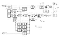
- FIG. 3 is a schematic diagram of the amplifier system including the predistorter in accordance with one or more embodiments of the present technique.
- FIG. 4 is a plot that illustrates output of an amplifier system, in accordance with one or more embodiments of the present technique
- FIG. 5 is a block diagram that depicts a system for populating a look-up table in accordance with one or more embodiments of the present technique.
- FIG. 6 is a block diagram that depicts a portion of the amplifier system implementing a look-up table in accordance with one or more embodiments of the present technique.
- certain embodiments of the present technique include a system and method for predistotion of an amplified signal.
- Certain embodiments include one or more digital predistotion techniques that can be implemented to help improve output performance/characteristics of an amplifier, such as a power amplifier (PA).
- predistortion is employed to reduce distortion in the output signal of a transmitter while maintaining a desired transmit (TX) power.
- predistortion is provided to compensate/offset distortion due to non-linearity of an amplifier, thereby helping to eliminate distortion at the output signal from a transmitter path of the amplifier (PA).
- predistortion is provided based on training or similar techniques used to characterize the amplifier.
- an active transmission signal is looped-back to an input of a receiver path, and the looped-back active transmission signal is used for training a predistorter to compensate for non-linearity in the transmit path.
- the transfer function of the PA may be estimated as a polynomial function, obtaining the coefficients of the polynomial function using adaptation techniques according to one of a number of possible different methods.
- the coefficients of the polynomial function may be obtained through curve fitting using a least mean square (LMS) algorithm.
- the amplifier employs a look-up method to configure the predistorter to account for non-linearity of the transmitter.
- the look-up method includes using a binning technique to characterize the output of the amplifier at various modes of operation.
- a look-up table includes coefficients or similar values that can be used to configure the predistorter.
- a look-up table is provided for one or more gain settings of the amplifier.
- a single look-up table may be provided for multiple operational modes (e.g., gain settings).
- the single look-up table includes coefficients/values that are scaled based on the operational mode (e.g., gain setting).
- the amplifier may employ the look-up method with little to no software/processing interaction.
- the amplifier circuitry e.g., the predistorter
- LMS least mean square
- the predistortion values/coefficients are used for performing predistortion to correct for potential non-linearity in the PA output due to the inherent non-linearity of the PA.
- predistortion techniques may be used to correct phase error.
- predistortion training and operation incorporates timing correction to properly align the phase of the received version of the original TX signal with the original TX signal.
- amplifier system 100 includes a transmitter or transceiver that employs a power amplifier (PA) for signal transmission.
- PA power amplifier
- amplifier system 100 includes a predistorter 102 and an amplifier 104 .
- Amplifier 104 may include a power amplifier (PA).
- PA power amplifier
- Amplifier 104 may include system components in addition to a PA.
- a PA of amplifier 104 may be preceded by linear stages such as baseband and PA driver circuitry.
- DAC digital to analog converter
- predistorter 102 may be employed to predistort the signal to be transmitted prior to the digital-to-analog conversion to compensate for potential non-linearity in the PA output.
- predistorter 102 and power amplifier 104 are arranged in series such that an input signal ‘x’ is first fed through predistorter 102 , generating a predistorted output signal ‘y’, which is then provided to power amplifier 104 as the amplifier input, where the amplifier yields the output signal ‘z’, as depicted.
- output signal ‘z’ may include a signal with reduced or no distortion (e.g., a non-distorted signal).
- a predistorter may be configured to pre-emphasize/amplify certain amplitude signals (e.g., higher amplitude signals) to ensure that the overall effective gain—of the predistorter stage and the amplifier stage as a whole—remains the same (e.g., having a linear relationship) regardless of the amplitude of the input.
- predistorter 102 may be configured to introduce an offsetting (e.g., negative or opposite) phase shift with respect to the inherent phase shift of the amplifier, such that the effective phase shift—of the predistorter stage and the amplifier stage together—is zero. This may ensure that the overall phase shift is constant regardless of the amplitude.
- FIG. 2 is a block diagram that depicts predistorter 102 in accordance with one or more embodiments of the present technique.
- predistorter 102 is able to provide distortion to the incoming signal to account for amplitude distortion and/or phase distortion.
- predistorter 102 includes an amplitude predistorter 106 and phase predistorter 108 .
- predistorter 102 may be provided with information (e.g., distortion information) representative of the amplitude and phase distortion introduced by amplifier 100 (e.g., distortion at power amplifier 104 ).
- predistorter 102 may be configured to obtain or acquire distortion information during a training operation/phase or similar calibration operation/phase.
- predistorter 102 may employ the distortion information to appropriately distort the amplitude and phase of signal ‘y’ being input to power amplifier 104 , such that output signal ‘z’ is an accurate amplified representation of input signal ‘x’.
- predistorter 102 includes a Cartesian to polar transformer 110 and a polar to Cartesian transformer 114 .
- Predistorter 102 may receive the transmit (TX) signal in Cartesian format (I+jQ) at Cartesian to polar transformer 110 .
- Cartesian to polar transformer 110 may analyze the TX signal and generate a corresponding magnitude/amplitude (r) and a phase ( ⁇ ) representative of the TX signal.
- the amplitude and phase of the TX signal may be predistorted in amplitude predistorter 106 and phase predistorter 108 , respectively, based on the distortion information.
- phase distortion 108 may be added to the current phase ( ⁇ ), as depicted at addition block 112 .
- the predistorted magnitude output from amplitude predistorter 106 and the predistorted phase output from phase predistorter 108 may be converted to Cartesian coordinates by polar to Cartesian transformer 114 .
- Predistorter 102 may use various methods to assess and determine how the appropriate amplitude distortion and/or phase distortion to account for amplitude distortion and/or phase distortion introduced in amplifier system 100 .
- training or test signals may be transmitted from the amplifier system 100 and assessed to determine a polynomial model corresponding to the transfer function of the amplifier.
- the polynomial model may be assessed to determine how gain and phase shifts should be varied as a function of the input amplitude.
- the coefficients of the polynomial may be estimated during a training phase of predistorter 102 , using one of a variety of possible adaptation techniques.
- value/coefficients may be estimated via reference to a look-up tale or similar technique that accesses stored distortion information, such as that stored in a look-up table (LUT). As described in more detail below, such a technique may use a binning technique to populate the look-up table with values. Referencing predetermined values may help to reduce the run-time processing load of the amplifier system 100 . This may be attributed to using predetermined values that can be easily retrieved with little to no software interaction (e.g., processing). Other embodiments may employ a variety of techniques to estimate the coefficients. In certain embodiments, for example, estimating the coefficients includes performing curve fitting, such a least-mean square (LMS) algorithm.
- LMS least-mean square
- Training of predistorter 102 may include functioning one or more portions of amplifier system 100 to provide distortion information and/or distortion values (e.g., coefficients) that may be used by predistorter 102 to determine how to implement amplitude and/or phase distortion. This period of operation may be referred to as predistorter training.
- predistorter 102 may enter a predistorter training mode to learn how to distort (e.g., pre-emphasize or predistort) the TX signal to yield a substantially linear signal at the overall output of amplifier system 100 .
- Predistorter training may be provided once (e.g., at start up) or may be repeated at various times (e.g., periodically, prior to a certain type of transmission, after a gain setting change, after a set number of transmissions, or the like). Predistorter training may be used to account for distortion characteristics of amplifier system 100 that may change over time. For example, inherent distortion at power amplifier 104 may vary with temperature and/or time.
- the desired predistorter polynomial coefficients may be estimated based on a reference (digital) input signal, which may be the actual TX signal—prior to its being converted to analog, upconverted to a RF band, and provided to the PA—and the PA output.
- the transmitter output e.g., the output of the PA
- the receiver path may include circuitry for downconverting the looped-back/received signal to a baseband for analysis.
- characteristics e.g., the number of samples employed at the transmitter and the receiver may be programmable.
- the received signal may be assed to determine distortion information (e.g., values and coefficients) that can be employed by predistorter 102 .
- the distortion information may be used to populate a look-up table with distortion information that can be used by predistorter 102 at a later time.
- a set of values/coefficients may be maintained for each transmitter gain setting (e.g., a table may be populated for each transmitter gain setting).
- the distortion information may be stored in a memory of predistorter 102 or another location of amplifier system 100 , such as an onboard memory.
- Predistorter 102 may reference a particular look-up table to obtain distortion information related to the current gain setting, in some embodiments.
- FIG. 3 is a partial logic diagram of a training portion 118 of amplifier system 100 in accordance with one or more embodiments of the present technique.
- training portion 118 includes a transmitter path 120 that is looped back to receiver path 122 via a loop-back path 124 .
- Training portion 118 may include various portions of amplifier system 100 that are reserved for training purposes and/or may include one or more portions of amplifier system 100 that may be used for other functions. For example, where amplifier system 100 is used as a transmitter, receiver path 122 may be reserved for training purposes only.
- receiver path 122 may include receiver circuitry used for receiving signals during normal receive operations as well as during training receive operations. For example, in the illustrated embodiment, the receive (RX) signal may be forwarded to another portion of amplifier system 100 and/or another device.
- training portion 118 includes predistorter 102 .
- Predistorter 102 may include circuitry used to distort the incoming transmit (TX) signal before it is transmitted by transmitter path 120 .
- amplitude and/or phase predistortion is provided at predistorter 102 to account for amplitude distortion and phase distortion that may otherwise be present in the output signal of amplifier system 100 .
- predistorter 102 is not activated during training operation. For example, during training operations, predistorter 102 may be provided in a dormant state that enables the substantially raw TX signal to be passed to through transmitter path 120 with no or minimal predistortion.
- Such an embodiment may enable the training to assess and determine appropriate predistortion based on the raw TX signal.
- predistortion may be applied at predistorter 102 during training such that the predistorted signal is passed through transmitter path 120 .
- training may assess and determine appropriate additional predistortion relative to the already distorted transmitted signal.
- output of predistorter 102 may be down-sampled, as depicted at down-sampling (DSMP) block 130 .
- the down-sampled signal may be used during the training operation.
- the down-sampled signal may be used to match slower sampling rates of the receiver path 122 with rates of the transmitter path 120 .
- down sampling may be a “2 ⁇ ” or “A” down-sampling where the transmitter path 120 is operating at about 176 megahertz (MHz) and the receiver path 122 is operating at about 88 MHz.
- output of predistorter 102 is passed to a programmable delay buffer (PDB) 134 and to a digital to analog converter (DAC) 136 .
- Delay buffer 134 may be used to delay passing of the signal from PDB 134 .
- PDB 134 may adequately compensate for processing delays. Such compensation for processing delays may help to ensure that signals of TX path 120 and RX path 122 are closely aligned. In some embodiments, adequate delay may be provided in one or both of TX path 120 and RX path 122 .
- coarse timing correlator 138 may appropriately program delay buffer 134 to delay the passage of TX signal according to the result of the coarse correlation operation.
- the output of the delay buffer 134 may be provided to a transmit (TX) Coordinate Rotation Digital Computer (CORDIC) 140 to generate magnitude (A TX ) and phase ( ⁇ TX ) information based on the TX signal.
- TX CORDIC 140 transmits (TX) Coordinate Rotation Digital Computer (CORDIC) 140 to generate magnitude (A TX ) and phase ( ⁇ TX ) information based on the TX signal.
- the input to TX CORDIC 140 is representative of the TX signal, prior to the digital form of the TX signal being converted to an analog signal by DAC 136 .
- DAC 136 may convert the TX signal from a digital to analog form. Output of DAC 136 (e.g., the analog baseband signal) may then be processed at transmit baseband processor (TXBP) 142 , upconverted to an RF band by upconverter 144 , and amplified by power amplifier (PA) circuit 146 of transmitter path 120 .
- PA circuit 146 may include PA drivers and/or a power amplifier, in some embodiments.
- the output of PA circuit 146 is the actual transmitted signal.
- Upconverter 144 may be driven by a local oscillator (LO) 145 . During normal transmission operations, the transmitted signal may be provided to antenna 148 for transmission.
- LO local oscillator
- the signal may be looped-back to receiver path 122 via loop-back path 124 .
- the loopback path may be switchably established, and may include capacitors or other circuitry.
- switch 150 of loop-back path 124 may be closed to enable loop-back of the transmitted signal to attenuator (ATTN) 152 .
- the output of PA 146 may thereby be coupled to the input of attenuator 152 .
- the attenuated analog RF band RX signal output from attenuator 152 may then be downconverted to an analog baseband signal by downconverter 154 .
- the same local oscillator (LO) 145 may be used to drive upconverter 144 and down-converter 154 .
- the use of the same oscillator may at least partially eliminate phase errors through loopback path 124 .
- the output of down-converter 154 may be provided to receive (RX) baseband processor (RXBP) 156 , and then amplified by variable gain amplifier (VGA) 158 .
- the gain of VGA 158 may be regulated/modified through an automatic gain control (AGC 2 ) 160 that receives the RX signal after it passes through ADC 162 .
- automatic gain control (AGC 2 ) 160 may operate to remove the DC signal component, correct for quadrature imbalance, and perform automatic gain control.
- the amplified analog baseband signal output from VGA 158 may be converted to a digital RX signal by analog to digital converter (ADC) 162 .
- ADC 162 may operate at a given sampling frequency.
- ADC 162 may operate at a (sampling) frequency of 88 MHz.
- Down-sampling at block 130 may correspond to the ratio of the operating frequency of the ADC 162 to DAC 136 of the transmitter path. For example, down-sampling by a factor of two (e.g., 2 ⁇ or 1 ⁇ 2 down-sampling) corresponds to the transmitter path 120 operating at a frequency of about 176 MHz and the receiver path 122 operating of a frequency of about 88 MHz.
- the receiver path sampling rate may be determined by the operating frequency of ADC 162 .
- the RX frequency may be lower than the TX frequency.
- a lower RX sampling frequency may allow for saving integrated circuit area, for example, and may be compensated for in various design modifications.
- the choice of TX and RX frequencies may be determined based on various systems and operating considerations, and a number of different frequencies may be considered when designing amplifier system 100 .
- the predistortion training principles set forth herein may be equally applied to operating frequencies different from the specific valued in the disclosed embodiments.
- the digital RX signal output from ADC 162 may be correlated with the down-sampled digital TX signal from downsampling block 130 , at coarse timing correlation block (CTC) 138 .
- coarse timing correlation e.g., up to 1 ⁇ 2 of the ADC sampling time
- CTC 138 may appropriately program delay buffer 134 to delay the TX signal according to the result of the coarse correlation operation.
- Correlation may be provided in multiple phases (e.g., coarse correlation and fine correlation). Correlation may reduce hardware (HW) requirements, and timing alignment may be performed up to a specified receiver frequency.
- coarse timing correlation may be performed as follows.
- the digital TX signal may pass through predistorter 102 without being predistorted (e.g., predistorter 102 may be disabled at this time), and may enter DAC 136 , where the TX signal may be converted to the analog baseband signal.
- the analog baseband signal may then be processed in TXBP 141 , and upconverted to RF band by upconverter 144 , amplified by PA 146 , and the transmitted signal may be looped/switched back via loop-back path 124 into attenuator 152 of receiver path 122 .
- the digital TX signal may be down-sampled by a specified factor, in this case two, at down-sampler 130 , to provide a reference to the RX signal obtained at the output of ADC 162 .
- fine timing correlation (e.g., up to 1 ⁇ 4 of the ADC sampling time) may be performed during a second stage of predistorter training. It should also be noted that in other embodiments, fine timing correlation may be performed up to a finer resolution than 1 ⁇ 4 of the ADC sampling time, when evaluating the PA transfer function as a polynomial with coefficients determined using an LMS algorithm, for example. Delaying the TX signal into TX CORDIC 140 effectively delays the input to DSMP 130 used for timing correlation. In some embodiments, the RX signal output of ADC 162 may be upsampled.
- the output from ADC 162 may be provided to finite impulse response filters (FIR) 164 and 166 , and to a fine-delay block 168 .
- FIR finite impulse response filters
- the fine aligning may be performed through banks of poly-phase filters operated at sub 88 MHz sample rates, each filter representing a step—e.g., eight stages when desiring 8 ⁇ upsampling or 2 stages when desiring 2 ⁇ upsampling—the correct phase selected from the filters.
- each filter in the filter bank may be correlated to the 176 MHz TX signal, and a correct phase may be selected from these separate correlation signals.
- the coefficients for the polynomials for predistorter 102 may be determined. Coefficients may be accurately determined once the TX and RX signals have been sufficiently aligned.
- a downsampled version of the digital TX signal (e.g., from downsampling block 130 ), may be provided to fine timing correlation blocks 164 , 166 , and 168 as a reference signal.
- the coefficients of polyphase filters 164 and 166 may be chosen to provide odd and even samples as if the output of ADC 162 were upsampled by a factor of two (e.g., 2 ⁇ upsampling).
- the filter outputs from FIR 164 , FIR 166 , and Delay 168 may be correlated to the downsampled TX signal in fine timing correlation blocks 170 , 172 and 174 , respectively, and the result provided to fine timing decision block (FTDB) 176 , which may assess and determine a final alignment and adjust programmable delay buffer 134 accordingly.
- FTDB fine timing decision block
- the phase that was selected for the TX signal for the coarse timing correlation may also be used for performing fine timing correlation.
- the output from ADC 162 may be provided to finite impulse response filters (FIR) 164 and 166 , and to a fine-delay block 176 .
- FIR finite impulse response filters
- a downsampled version of the digital TX signal may be provided to fine timing correlation blocks 170 , 172 , and 174 as the reference signal.
- the coefficients of filters 164 and 166 may be chosen to provide odd and even samples as if the output of single ADC 162 were upsampled by a factor of two.
- FIR filters 164 and 166 allow for fine-tuning by adjusting the signal in fractional steps, from odd to even phase or even to odd phase.
- Delay block 168 may provide a means for delaying a whole step when applicable.
- FTC blocks 170 , 172 , 174 may perform the RX signal interpolation, and once the correct phase for the RX signal has been determined, the corresponding transmitter phase (odd or even), which would be time aligned with the output signal of ADC 162 , may be selected. This may allow for shutting down FIR filter stages 164 and 166 . Otherwise, the phase that was selected for the TX signal for the coarse timing correlation may be used while running the correct FIR filter (corresponding to the correct phase) to generate a fine timed RX signal.
- phase distortion characteristics of the PA may be determined via the loopback technique for the analog portion of the TX path 120 and/or the RX path 122 .
- Driving upconverter 144 and downconverter 154 with the same local oscillator (LO) 145 may facilitate correlation of the phase noise that may cancel out in the loop-back path.
- LO local oscillator
- One advantage of using the loop-back path is the capability it provides to discern the phase irregularities within the complete analog chain, regardless of where the TX PA is configured, e.g., regardless of whether the TX PA is on the same IC as the rest of amplifier system 100 or separate. Therefore, predistortion for amplifier system 100 may be performed for the entire transmitter path 120 , not just for PA 146 itself.
- the original digital TX signal (e.g., the TX signal prior to reaching DAC 136 ) may be provided to transmit (TX) CORDIC 140 via PDB 134
- the final RX digital signal (e.g., the digital RX signal output by ADC 162 ) may be provided to receive (RX) CORDIC 180 , during the training phase, to generate the amplitude (A TX and ARx) and/or phase ( ⁇ TX and ⁇ RX ) information used to determine the coefficients/values for use in predistortion (e.g., for populating one or more LUTs).
- the amplitude (A TX and A RX ) and/or phase ( ⁇ TX and ⁇ RX ) information is provided to a predistortion trainer and controller block (PTC) 182 , which may operate to provide predistortion information to and/or configure predistorter 102 in accordance with predistortion information assessed and determined during a training operation.
- PTC 304 may compare the respective amplitude and phase information of the two signals, e.g., compare the amplitude and phase information representative of the TX signal to the amplitude and phase information representative of the RX signal, respectively.
- the TX signal may be considered a ‘before’ signal in the sense that it represents the TX signal before it enters the transmit path via DAC 136 , and consequently before it enters PA 146 .
- the RX signal may be considered the ‘after’ signal in the sense that it represents the original TX signal but after it has traveled through the transmit path 120 , exited PA 146 , and looped-back through the receive path 122 where it has been digitized by ADC 162 .
- PTC 304 may obtain values/coefficients for predistorter 306 based on the comparison of the two signals, and provide those values/coefficients to predistorter 102 .
- the values/coefficients obtained at PTC 304 may then be used by predistorter 102 to predistort the amplitude and/or phase of the TX signal during regular transmissions.
- AGC 2 160 may be used to size the signal only during the predistorter training, and sizing of an actual RX signal during regular transmission may be performed through an AGC 184 .
- the loop-back path 124 and receiver path 122 may be configured on the same integrated circuit (chip) as transmitter path 120 , and may be switchably established between the output to antenna 148 and receiver path 122 .
- the loop-back may be established outside the chip/circuitry containing the transmitter path 120 .
- the loop-back path 124 is meant to be established during training, and may be disconnected thereafter to allow amplifier system 100 to perform regular transmission and reception of signals.
- amplifier system 100 may include amplifier configurations, such at those described in co-pending U.S. patent application Ser. No. 12/580,709, entitled “Power Amplifier Linearization Using Digital Predistortion” by Peiris et al., filed Oct. 16, 2009, which is incorporated by reference in its entirety as if set forth herein.
- a filter (not shown) may also be provided in the receiver stage 122 , e.g., between attenuator 152 and ADC 162 .
- the bandwidth of this filter may be broadened in order to not lose the non-linearity (side lobe information). That is, during predistorter training, the filter bandwidth may be relaxed to provide more accurate characterization.
- Predistorter 102 may also be configured to store different sets of coefficients for one or more gain setting, from which the appropriate set of values/coefficients may be selected and used for predistortion during normal transmission.
- predistortion information e.g., values/coefficients
- predistortion information based on the results of the training operation may be stored in a memory and retrieved at a later time.
- a look-up table (LUT) method is used to store/retrieve the appropriate predistortion information based on the distortion characteristics assessed and determined during the training operation.
- the predistorter provides a predistortion based on predistortion information acquired during the training portion.
- the predistortion information is stored in a memory location and may be retrieved/accessed to determine if and how predistortion should be applied to the signal output by amplifier system 100 .
- the predistorter may retrieve values/coefficients indicative of the difference and appropriately modify the signal such that the resulting output accounts for the non-linearity, and outputs a signal at the desired level.
- the predistortion information is provided via a look-up table.
- a look-up table includes a plurality of output vales versus input values.
- the predistorter may assess the relationships and, where a given output is desired, select the complementary input value to provide the desired output. Accordingly, in some embodiments, predistorter 102 may adjust/offset the input signal based on predistortion information stored in the look-up table, to provide an output that compensates for non-linearity of amplifier system 100 .
- FIG. 4 is a plot 200 that illustrates amplifier system output (linear and non-linear), in accordance with one or more embodiments of the present technique.
- the x-axis represents an amplifier input (e.g., input to DAC 136 of FIG. 3 ) and the y-axis represents the amplifier output (e.g., output from PA 146 of FIG. 3 ).
- the y-axis is scaled in accordance with the full-range resolution of the input (e.g., in accordance with the full resolution of ADC 162 ).
- the full scale is adjusted to fit within hardware.
- the y-scale is modified to 0 to 736 to align with hardware.
- the y-scale is split into ranges.
- the 32-size bins are represented by the increments of 32 along the y-axis having a bin that extends +/ ⁇ 16 from the demarcated increment.
- the points 210 and 212 are representative of two of those increments. For example, where point 210 is representative of the next increment after 64, the increment at point 210 has a y-value of 96 and the increment at point 212 has a y-value of 128.
- a first curve includes a linear relationship represented by dashed line (linear curve) 216 .
- Linear curve 216 is representative of a linear relationship, where the output (y-axis) includes a linear relationship with regard to the input (x-axis).
- the linear curve may be representative of a relatively proportional amplitude/phase output (y-axis) of amplifier system 100 across all input amplitude (x-axis).
- a second curve includes a non-linear relationship represented by solid line (non-linear curve) 218 .
- Non-linear curve 218 may be representative of a non-linear relationship, where the amplitude/phase output (y-axis) of amplifier system 100 includes a non-linear relationship with regard to the amplitude/phase input (x-axis).
- the non-linear curve may be representative of a disproportionately lower amplitude output (y-axis) at higher gain values (x-axis).
- linear curve 216 may be representative of a desired output of amplifier system 100 , where as the non-linear curve 218 may be representative of the actual output of amplifier system 100 (e.g., without implementing predistortion).
- linear curve 216 and/or non-linear curve 218 are assessed and determined using a binning technique.
- binning includes observing the responses (e.g., the received output) over a wide variety of inputs, grouping the values into ranges (e.g., bins) and averaging these values as over the ranges to provide discrete points on the plot that are representative of the relationship between the inputs and the outputs.
- binning includes dividing the output (e.g., the y-axis) into discrete bins, and averaging the output values for the points that fall within each bin to determine an average output bin value for a set of points within the bin, as well as averaging the input values for the points that fall within the bin to determine an average input bin value for the set of points.
- the average output bin value and the average input bin value are paired as a representative point on a curve representing the actual response of amplifier system 100 (e.g., non-linear curve 218 ).
- the bins are sized to match the increment of the y-axis and, thus, extend above the increment by 1 ⁇ 2 the bin size and below the increment by 1 ⁇ 2 the bin size.
- the bin e.g., having a size 32
- the y-values and x-values of the resulting outputs obtained during training over a range of inputs having an output (y) that falls within the range of 48 to 80 may be averaged to provide the y and x value of bin point 220 .
- Non-linear curve 218 may be representative of multiple bin points resulting from such a technique.
- curve 218 includes average points at bins centered at 0, 32, 64, point 210 , point 212 , and so forth. Note, the bin at zero extends from 0 to 16, but may not include negative values.
- linear curve 216 may be obtained based on non-linear curve 218 .
- linear curve 216 includes a line that is tangent to non-linear curve 218 at one or more locations. In the illustrated embodiment, for example, linear curve 216 is tangent to non-linear curve 216 at lower input values (e.g., smaller x values). In one embodiment, linear curve 216 may be tangent to two or more of the first bin points. For example, in one embodiment, linear curve 216 may be a line that extends through the bin point at (0,0) and the bin point of the adjacent bin (e.g., bin point 222 of the bin associated with output value 32). In some embodiments, plots are provided for one or more modes of operations.
- a plot similar to plot 200 is provided for each gain setting of amplifier system 100 .
- none or a single plot may be provided at gain settings where non-linearity is not present (e.g., lower gain settings), or where non-linearity is not expected to be present.
- One or more plots may be provided for higher gain settings where non-linearity is present or is expected to be present.
- FIG. 5 is a block diagram that depicts a distortion information system 250 for populating a look-up table 252 in accordance with one or more embodiments of the present technique.
- distortion information system 250 may be provided in predistortion trainer and controller block (PTC) 182 and/or predistorter 102 (See FIG. 3 ).
- PTC predistortion trainer and controller block
- system 250 may populate loop-up table 252 in a memory of PTC 182 , predistorter 102 , or another location in amplifier system 118 .
- the stored information may be accessed and retrieved by PTC 182 and/or predistorter for determining how to predistort a TX signal.
- transmission information is received at transmission input block 254 and receive information is received at receive input block 256 .
- transmission information is provided from transmit CORDIC 140 and/or receive information is provided from receive CORDIC 180 (See FIG. 3 ).
- Transmission information may include amplitude and/or phase information.
- the transmission information and the receive information comprises a set of amplitude and/or phase information paired with one another.
- the receive information may be representative of the received signal that was produced as a result of the transmitted signal associated with the transmission information.
- the transmit information may be representative of the digital signal to be output before being converted to an analog signal by DAC 136
- the receive information may be representative of the resulting received analog signal after it has be converted to a digital signal at ADC 162 .
- the receive information is provided to bin address block 258 .
- Bin address block 258 may assess the received information to determine what bin the information should be associated with. For example, where the receive information includes an amplitude/phase that is in the range of 48 to 80 (See FIG. 4 ), bin address block 258 may associate the transmission information and the receive information with bin address 62 .
- the bin address provided by bin address block 258 may be forwarded to multiplexer (MUX) 268 such that it can associate the incoming transmission and receive information with the correct cell/address (bin) of lookup table 252 .
- MUX multiplexer
- the receive information may be assessed at bin address block 258 such that the appropriate bin address can be determined and passed to MUX 268 .
- information e.g., the transmission and receive information
- look-up table 252 includes a line associated with each bin address.
- the lines are representative of multiple input and output samples based on the transmission and receive information. For example, in some embodiments, such as that depicted in FIG. 5 , an assembled line of bin data 270 is assembled prior to being added to look-up table 252 .
- line of bin data 270 includes an input samples block 270 a representative of input samples, which may be indicative of the transmission information and/or the input signal, an output samples block 270 b representative of output samples, which may be indicative of the receive information and/or the actual input signal received from ADC 162 , and a number of samples block 270 c that may reflect the number of times transmission and receive data sets have been added to the respective bin (e.g., the total number of samples in the bin).
- the line of bin data 270 associated with the determined bin address is retrieved, and the transmission data and the receive data is added to the list of samples in the line of data as depicted at adders 272 and 274 .
- the number of samples is updated (e.g., incremented +1) at incrementer 276 to reflect another sample being added to the assembled line of bin data.
- a list of the input samples and the output samples may be maintained in each of the input samples block 270 a and the output samples block 270 b .
- the total of the values in each block ( 270 a and 270 b ) may be divided by the number of samples.
- the resulting average values for input samples block 270 a and output samples block 270 b may be representative of a bin point.
- the average value of input samples block 270 a may be representative of the x-axis value of bin point 220 (See FIG. 3 )
- average value the output sample block 270 b may be representative of the y-axis value of bin point 220 , where assembled line of bin data is associated with a bin address of “62” as determined at bin address block 258 .
- an average value for the input samples block 270 a and/or output samples block 270 b may be maintained. For example, as values are added to blocks 270 a and 270 b , the total value may be averaged based on the number of samples. In such an embodiment, a separate technique may be used to keep a running average and number of samples block 270 a may not be necessary.
- the data populated to look-up table 252 is accessible such that a portion of amplifier system 100 may use the stored information to assess and determine what, if any, predistortion should be applied and/or how it should be applied.
- look-up table 252 may be accessed via a read/write (R/W) path 280 .
- R/W path 280 may be accessible by PTC 182 and/or distorter 102 .
- the distortion information stored in look-up table 252 may be representative of a curve similar to that of non-linear curve 218 depicted in FIG. 4 .
- each line of line of bin data 270 may be associated with one or more of the bin points that define non-linear curve 218 .
- predistortion may be provided to amplifier system 100 based on the differences between non-linear curve 218 and linear curve 216 .
- the magnitude of the input may be increased (e.g., to an adjusted input value) such that the resulting output more closely tracks that of linear curve 216 .
- the adjusted input value is applied to the signal to be transmitted such that is adjusted/predistorted prior to being transmitted.
- an output level (“y”) associated with an output point 290 is desired, instead of using an input value associated with the value (“x 0 ”) of output point 290 , an adjusted “x 1 ” value is used associated with bin point 292 , such that the resulting output level is that same or similar that of output point 290 .
- the desired output level may not be at or near the level of a bin point.
- the input level may be determined by interpolating between two or more bin points. For example, where the desired output level is that of output point 294 , interpolation between the two adjacent bin points 292 and 296 may be provided to assess and determine an input value that may provide an output level at or near the desired output level. In one embodiment, a linear interpolation between the two points may be provided. In one such embodiment, the adjusted input value (x adjust ) may be determined as:
- x adjust x 1 + [ ( x 2 - x 1 ⁇ y ) * ( y - y ⁇ ⁇ ⁇ y ) ] ( 1 )
- y is the desired output level
- x 1 is the input value of the first bin point (e.g., bin point 292 )
- x 2 is the input value of the second bin point (e.g., bin point 296 )
- ⁇ y is difference between the output level at each bin point (e.g., the bin size, such as 32 between points 292 and 296 ).
- An adjusted point 300 may include (x adjust , y).
- multiple tables may be provided to characterize the predistortion for amplifier system 100 .
- a table may be provided for each gain of the amplifier, or for each gain where non-linearity may occur in which predistortion may be useful. For example, in some embodiments, lower gains may not be associated with a look-up table, whereas higher gains may be associated with look-up tables to provide predistortion information to the predistorter.
- the look-up table may be referenced/selected based on the gain of amplifier system 100 .
- FIG. 6 is a block diagram that depicts a look-up portion 302 of amplifier system 100 implementing one or more look-up tables in accordance with one or more embodiments of the present technique.
- look-up portion 302 includes a gain input to predistortion enable (PE) block 304 .
- PE block 304 may assess the gain input to determine whether or not to implement predistortion. For example, if the gain is associated with little to no non-linearity, PE 304 may provide an output to disable predistortion, as it may be expected that the output falls at or near the desired output level without predistortion.
- PE predistortion enable
- PE 304 may provide an output to enable predistortion, as it is expected the output may fall too far from the desired output level.
- an enable signal is passed to a multiplexer 306 that may be used to implement predistortion or forward (e.g., without predistortion) the input signal to be transmitted. For example, where predistortion is disabled, the raw input signal (e.g., TX signal) may be routed to and through MUX 306 without having predistortion applied to the signal.
- the gain may be assessed to determine which look-up table should be used. Where only one look-up table is present, such a step may not be necessary and the system may apply distortion based on the single look-up table.
- a single look-up table may be used, and values may be scaled to account for variations in gains other than the gain used to assess the LUT. For example, the look-up is done based on a signal prescaled to account for the difference between the desired gain and the gain at which predistortion calibration is done.
- power amplifier 104 is modeled as a power amplifier with a single gain setting preceded by a linear amplifier stages which may have variable gain settings. These linear stages can be either baseband or RF amplifiers.
- power amplifier 104 is trained for the highest acceptable power level (e.g., at the highest usable gain settings for linear stages).
- the derived pre-distorter table can be directly used for that particular gain setting. In the single table approach, this derived pre-distorter table is used for a set of gain settings lower than the trained gain setting without further training.
- This may include simply pre-scaling the signal at the input to pre-distorter 102 and by post scaling the signal at output of pre-distorter 102 (e.g., as derived for the highest gain setting).
- pre-scaling factor is selected to be:
- Prescalingfactor G target G trained ( 2 ) and the post scaling factor to be:
- Postscalingfactor G trained G target ( 3 ) the combined pre-scalar, pre-distorter derived at G trained and post-scalar will act as a pre-distorter created by training at G target .
- Knowledge of absolute gain values (which might change with temperature) of linear stages is not required, as a knowledge of the ratio of gain difference may be sufficient and doest not normally changes with the temperature.
- PE 304 may provide an output that is used to determine the correct look-up table to use. For example, where a look-up table is associated with the gain, the PE 304 may activate the associated look-up table for use. In one embodiment, for instance, lower gain values may be associated with a small gain look-up table 308 , and higher gain values may be associated with a higher gain look-up table 310 . In some embodiments where the small gain lookup table 308 is used, look-up values and/or scaling may be applied, as depicted at scaling block 312 .
- the scaled input may be associated with the signal information provided from TX CORDIC 140 , and passed directly to predistortion amplitude and scaling (PDAS) block 142 , or passed to index block 144 .
- Index block 144 may extract the desired output level (y) such that the appropriate line of bin data 270 of look-up table 310 may be assessed.
- the lines of bin data associated with the bounding bin points may be extracted for use at PDAS 142 . For example, with reference to FIG. 4 , where the desired level is “y”, the lines of bin data associated with bin points 296 and 292 may be extracted.
- the extracted data from lookup table 310 may be passed to PDAS 142 .
- PDAS 142 may assess the extracted data to determine the appropriate predistortion to apply.
- an input to PDAS 142 may include the desired output (e.g., “y”) and, PDAS 142 may linearly interpolate between the two bounding lines of bin data extracted to determine the desired adjustment/predistortion to be applied to the TX signal.
- PDAS 142 may provide an adjusted value to CORDIC 314 , and CORDIC 314 may assess the information provided from TX CORDIC 140 (e.g., amplitude and phase information) and the adjusted value provided by PDAS 142 , and PDAS 142 may output an associated predistorted signal for output from MUX 306 .
- the predistorted TX signal may be transmitted and output via transmitter path 120 , for instance (See FIG. 3 ).
- look-up table may be provided for one or both of adjusted amplitude and adjusted phase values.
Abstract
Description
where y is the desired output level, x1 is the input value of the first bin point (e.g., bin point 292), x2 is the input value of the second bin point (e.g., bin point 296), and Δy is difference between the output level at each bin point (e.g., the bin size, such as 32 between
and the post scaling factor to be:
the combined pre-scalar, pre-distorter derived at Gtrained and post-scalar will act as a pre-distorter created by training at Gtarget. Knowledge of absolute gain values (which might change with temperature) of linear stages is not required, as a knowledge of the ratio of gain difference may be sufficient and doest not normally changes with the temperature.
Claims (18)
Priority Applications (1)
| Application Number | Priority Date | Filing Date | Title |
|---|---|---|---|
| US12/580,836 US8340602B1 (en) | 2009-10-16 | 2009-10-16 | Power amplifier linearization system and method |
Applications Claiming Priority (1)
| Application Number | Priority Date | Filing Date | Title |
|---|---|---|---|
| US12/580,836 US8340602B1 (en) | 2009-10-16 | 2009-10-16 | Power amplifier linearization system and method |
Publications (1)
| Publication Number | Publication Date |
|---|---|
| US8340602B1 true US8340602B1 (en) | 2012-12-25 |
Family
ID=47359749
Family Applications (1)
| Application Number | Title | Priority Date | Filing Date |
|---|---|---|---|
| US12/580,836 Expired - Fee Related US8340602B1 (en) | 2009-10-16 | 2009-10-16 | Power amplifier linearization system and method |
Country Status (1)
| Country | Link |
|---|---|
| US (1) | US8340602B1 (en) |
Cited By (14)
| Publication number | Priority date | Publication date | Assignee | Title |
|---|---|---|---|---|
| US20110250853A1 (en) * | 2010-04-09 | 2011-10-13 | Andrea Camuffo | Operating point setting of an amplifier |
| US20120177368A1 (en) * | 2011-01-07 | 2012-07-12 | Fujitsu Limited | Optical transmission apparatus and analog-to-digital conversion apparatus |
| US20140177755A1 (en) * | 2012-12-21 | 2014-06-26 | Mediatek Singapore Pte. Ltd. | Rf transmitter, integrated circuit device, wireless communication unit and method therefor |
| CN104113382A (en) * | 2013-04-22 | 2014-10-22 | 瑞昱半导体股份有限公司 | Wireless transmission system and method for determining preset gain of wireless transmission system |
| US8995572B1 (en) | 2010-04-16 | 2015-03-31 | Marvell International Ltd. | Digital Predistortion for nonlinear RF power amplifiers |
| US9002302B1 (en) * | 2009-08-21 | 2015-04-07 | Marvell International Ltd. | Digital Predistortion for nonlinear RF power amplifiers |
| WO2015050978A1 (en) | 2013-10-02 | 2015-04-09 | Nokia Solutions And Networks Oy | Using fractional delay computations to improve intermodulation performance |
| US9160586B1 (en) | 2013-07-24 | 2015-10-13 | Marvell International Ltd. | Method and apparatus for estimating and compensating for in-phase and quadrature (IQ) mismatch in a receiver of a wireless communication device |
| TWI508463B (en) * | 2013-04-16 | 2015-11-11 | Realtek Semiconductor Corp | Wireless transmission system, and method for determining default gain thereof |
| US20170048007A1 (en) * | 2015-08-12 | 2017-02-16 | Samsung Electronics Co., Ltd | Operation method of electronic device for transmitting rf signal and electronic device thereof |
| KR20170019800A (en) * | 2015-08-12 | 2017-02-22 | 삼성전자주식회사 | A operating method of electronic apparatus for transmitting rf signal and electronic apparatus |
| US10511357B2 (en) | 2017-12-12 | 2019-12-17 | At&T Intellectual Property I, L.P. | Detection scheme utilizing transmitter-supplied non-linearity data in the presence of transmitter non-linearity |
| US10924068B2 (en) | 2019-02-27 | 2021-02-16 | Texas Instruments Incorporated | Digital predistortion calibration |
| US20220286151A1 (en) * | 2021-03-05 | 2022-09-08 | Motorola Solutions, Inc. | Linearizing narrowband carriers with low resolution predistorters |
Citations (29)
| Publication number | Priority date | Publication date | Assignee | Title |
|---|---|---|---|---|
| US5049832A (en) * | 1990-04-20 | 1991-09-17 | Simon Fraser University | Amplifier linearization by adaptive predistortion |
| US5867065A (en) * | 1997-05-07 | 1999-02-02 | Glenayre Electronics, Inc. | Frequency selective predistortion in a linear transmitter |
| US5923712A (en) * | 1997-05-05 | 1999-07-13 | Glenayre Electronics, Inc. | Method and apparatus for linear transmission by direct inverse modeling |
| US20050143027A1 (en) | 2003-12-26 | 2005-06-30 | Hiddink Gerrit W. | Method and apparatus for automatic data rate control in a wireless communication system |
| US6985704B2 (en) * | 2002-05-01 | 2006-01-10 | Dali Yang | System and method for digital memorized predistortion for wireless communication |
| US7139534B2 (en) | 2003-03-05 | 2006-11-21 | Matsushita Electric Industrial Co., Ltd. | Transmission circuit |
| US7184721B2 (en) | 2003-10-06 | 2007-02-27 | Texas Instruments Incorporated | Transmit power control in a wireless communication device |
| US7274748B1 (en) | 2004-06-02 | 2007-09-25 | Rf Micro Devices, Inc. | AM to FM correction system for a polar modulator |
| US7346317B2 (en) | 2005-04-04 | 2008-03-18 | Freescale Semiconductor, Inc. | Dynamic gain and phase compensation for power amplifier load switching |
| US7348844B2 (en) * | 2005-07-21 | 2008-03-25 | Alcatel | Adaptive digital pre-distortion system |
| US20090061919A1 (en) | 2007-09-04 | 2009-03-05 | Broadcom Corporation | Power consumption management based on transmit power control data and method for use therewith |
| US7551686B1 (en) | 2004-06-23 | 2009-06-23 | Rf Micro Devices, Inc. | Multiple polynomial digital predistortion |
| US20090256630A1 (en) * | 2008-04-11 | 2009-10-15 | Michael Lee Brobston | Method of power amplifier predistortion adaptation using compression detection |
| US7653410B2 (en) | 2004-12-08 | 2010-01-26 | Sharp Kabushiki Kaisha | Radio communication device, radio communication system and measurement method capable of conducting appropriate transmit power control |
| US7653147B2 (en) | 2005-08-17 | 2010-01-26 | Intel Corporation | Transmitter control |
| US20100035554A1 (en) | 2008-08-05 | 2010-02-11 | Seydou Nourou Ba | Adaptive Complex Gain Predistorter for a Transmitter |
| US7724840B2 (en) * | 2006-12-19 | 2010-05-25 | Crestcom, Inc. | RF transmitter with predistortion and method therefor |
| US20100197365A1 (en) | 2007-06-26 | 2010-08-05 | Skyworks Solutions, Inc. | Error vector magnitude control within a linear transmitter |
| US7848717B2 (en) | 2004-12-21 | 2010-12-07 | Zte Corporation | Method and system for out of band predistortion linearization |
| US20100311360A1 (en) * | 2009-06-08 | 2010-12-09 | Fong-Ching Huang | Transmitter, method for lowering signal distortion, and method for generating predistortion parameters utilized to lower signal distortion |
| US7894844B2 (en) | 2003-12-26 | 2011-02-22 | Agere Systems Inc. | Method and apparatus for automatic transmit power variation in a wireless communication system |
| US7899416B2 (en) * | 2007-11-14 | 2011-03-01 | Crestcom, Inc. | RF transmitter with heat compensation and method therefor |
| US7904033B1 (en) * | 2001-11-21 | 2011-03-08 | Pmc-Sierra, Inc. | Constant gain digital predistortion controller for linearization of non-linear amplifiers |
| US7940198B1 (en) | 2008-04-30 | 2011-05-10 | V Corp Technologies, Inc. | Amplifier linearizer |
| US7940120B2 (en) | 2008-09-09 | 2011-05-10 | Alcatel Lucent | Power amplifier linearization using RF feedback |
| US8064851B2 (en) * | 2008-03-06 | 2011-11-22 | Crestcom, Inc. | RF transmitter with bias-signal-induced distortion compensation and method therefor |
| US8150336B2 (en) * | 2007-08-21 | 2012-04-03 | Texas Instruments Incorporated | Apparatus and method for adaptive polar transmitter linearization and wireless transmitter employing the same |
| US8170507B2 (en) * | 2008-10-29 | 2012-05-01 | Texas Instruments Incorporated | Predistortion methods and apparatus for transmitter linearization in a communication transceiver |
| US8195103B2 (en) * | 2006-02-15 | 2012-06-05 | Texas Instruments Incorporated | Linearization of a transmit amplifier |
-
2009
- 2009-10-16 US US12/580,836 patent/US8340602B1/en not_active Expired - Fee Related
Patent Citations (31)
| Publication number | Priority date | Publication date | Assignee | Title |
|---|---|---|---|---|
| US5049832A (en) * | 1990-04-20 | 1991-09-17 | Simon Fraser University | Amplifier linearization by adaptive predistortion |
| US5923712A (en) * | 1997-05-05 | 1999-07-13 | Glenayre Electronics, Inc. | Method and apparatus for linear transmission by direct inverse modeling |
| US6141390A (en) * | 1997-05-05 | 2000-10-31 | Glenayre Electronics, Inc. | Predistortion in a linear transmitter using orthogonal kernels |
| US5867065A (en) * | 1997-05-07 | 1999-02-02 | Glenayre Electronics, Inc. | Frequency selective predistortion in a linear transmitter |
| US7904033B1 (en) * | 2001-11-21 | 2011-03-08 | Pmc-Sierra, Inc. | Constant gain digital predistortion controller for linearization of non-linear amplifiers |
| US6985704B2 (en) * | 2002-05-01 | 2006-01-10 | Dali Yang | System and method for digital memorized predistortion for wireless communication |
| US7139534B2 (en) | 2003-03-05 | 2006-11-21 | Matsushita Electric Industrial Co., Ltd. | Transmission circuit |
| US7184721B2 (en) | 2003-10-06 | 2007-02-27 | Texas Instruments Incorporated | Transmit power control in a wireless communication device |
| US7894844B2 (en) | 2003-12-26 | 2011-02-22 | Agere Systems Inc. | Method and apparatus for automatic transmit power variation in a wireless communication system |
| US20050143027A1 (en) | 2003-12-26 | 2005-06-30 | Hiddink Gerrit W. | Method and apparatus for automatic data rate control in a wireless communication system |
| US7274748B1 (en) | 2004-06-02 | 2007-09-25 | Rf Micro Devices, Inc. | AM to FM correction system for a polar modulator |
| US7551686B1 (en) | 2004-06-23 | 2009-06-23 | Rf Micro Devices, Inc. | Multiple polynomial digital predistortion |
| US7653410B2 (en) | 2004-12-08 | 2010-01-26 | Sharp Kabushiki Kaisha | Radio communication device, radio communication system and measurement method capable of conducting appropriate transmit power control |
| US7848717B2 (en) | 2004-12-21 | 2010-12-07 | Zte Corporation | Method and system for out of band predistortion linearization |
| US7346317B2 (en) | 2005-04-04 | 2008-03-18 | Freescale Semiconductor, Inc. | Dynamic gain and phase compensation for power amplifier load switching |
| US7348844B2 (en) * | 2005-07-21 | 2008-03-25 | Alcatel | Adaptive digital pre-distortion system |
| US7653147B2 (en) | 2005-08-17 | 2010-01-26 | Intel Corporation | Transmitter control |
| US8195103B2 (en) * | 2006-02-15 | 2012-06-05 | Texas Instruments Incorporated | Linearization of a transmit amplifier |
| US7724840B2 (en) * | 2006-12-19 | 2010-05-25 | Crestcom, Inc. | RF transmitter with predistortion and method therefor |
| US20100197365A1 (en) | 2007-06-26 | 2010-08-05 | Skyworks Solutions, Inc. | Error vector magnitude control within a linear transmitter |
| US8150336B2 (en) * | 2007-08-21 | 2012-04-03 | Texas Instruments Incorporated | Apparatus and method for adaptive polar transmitter linearization and wireless transmitter employing the same |
| US20090061919A1 (en) | 2007-09-04 | 2009-03-05 | Broadcom Corporation | Power consumption management based on transmit power control data and method for use therewith |
| US7899416B2 (en) * | 2007-11-14 | 2011-03-01 | Crestcom, Inc. | RF transmitter with heat compensation and method therefor |
| US8064851B2 (en) * | 2008-03-06 | 2011-11-22 | Crestcom, Inc. | RF transmitter with bias-signal-induced distortion compensation and method therefor |
| US20090256630A1 (en) * | 2008-04-11 | 2009-10-15 | Michael Lee Brobston | Method of power amplifier predistortion adaptation using compression detection |
| US7940198B1 (en) | 2008-04-30 | 2011-05-10 | V Corp Technologies, Inc. | Amplifier linearizer |
| US8055217B2 (en) * | 2008-08-05 | 2011-11-08 | Texas Instruments Incorporated | Adaptive complex gain predistorter for a transmitter |
| US20100035554A1 (en) | 2008-08-05 | 2010-02-11 | Seydou Nourou Ba | Adaptive Complex Gain Predistorter for a Transmitter |
| US7940120B2 (en) | 2008-09-09 | 2011-05-10 | Alcatel Lucent | Power amplifier linearization using RF feedback |
| US8170507B2 (en) * | 2008-10-29 | 2012-05-01 | Texas Instruments Incorporated | Predistortion methods and apparatus for transmitter linearization in a communication transceiver |
| US20100311360A1 (en) * | 2009-06-08 | 2010-12-09 | Fong-Ching Huang | Transmitter, method for lowering signal distortion, and method for generating predistortion parameters utilized to lower signal distortion |
Cited By (31)
| Publication number | Priority date | Publication date | Assignee | Title |
|---|---|---|---|---|
| US9002302B1 (en) * | 2009-08-21 | 2015-04-07 | Marvell International Ltd. | Digital Predistortion for nonlinear RF power amplifiers |
| US9668208B2 (en) | 2010-04-09 | 2017-05-30 | Intel Deutschland Gmbh | Operating point setting of an amplifier |
| US20110250853A1 (en) * | 2010-04-09 | 2011-10-13 | Andrea Camuffo | Operating point setting of an amplifier |
| US8995572B1 (en) | 2010-04-16 | 2015-03-31 | Marvell International Ltd. | Digital Predistortion for nonlinear RF power amplifiers |
| US9363022B2 (en) * | 2011-01-07 | 2016-06-07 | Fujitsu Limited | Optical transmission apparatus and analog-to-digital conversion apparatus |
| US20120177368A1 (en) * | 2011-01-07 | 2012-07-12 | Fujitsu Limited | Optical transmission apparatus and analog-to-digital conversion apparatus |
| US20140177755A1 (en) * | 2012-12-21 | 2014-06-26 | Mediatek Singapore Pte. Ltd. | Rf transmitter, integrated circuit device, wireless communication unit and method therefor |
| US9813086B2 (en) * | 2012-12-21 | 2017-11-07 | Mediatek Singapore Pte. Ltd | RF transmitter, integrated circuit device, wireless communication unit and method therefor |
| TWI508463B (en) * | 2013-04-16 | 2015-11-11 | Realtek Semiconductor Corp | Wireless transmission system, and method for determining default gain thereof |
| US9215014B2 (en) | 2013-04-16 | 2015-12-15 | Realtek Semiconductor Corp. | Wireless transmission system, and method for determining default gain of wireless transmission system |
| CN104113382B (en) * | 2013-04-22 | 2016-08-03 | 瑞昱半导体股份有限公司 | Wireless transmitting system and determine the method for preset gain of wireless transmitting system |
| CN104113382A (en) * | 2013-04-22 | 2014-10-22 | 瑞昱半导体股份有限公司 | Wireless transmission system and method for determining preset gain of wireless transmission system |
| US9160586B1 (en) | 2013-07-24 | 2015-10-13 | Marvell International Ltd. | Method and apparatus for estimating and compensating for in-phase and quadrature (IQ) mismatch in a receiver of a wireless communication device |
| US9755583B2 (en) | 2013-10-02 | 2017-09-05 | Nokia Solutions And Networks Oy | Using fractional delay computations to improve intermodulation performance |
| CN105765860A (en) * | 2013-10-02 | 2016-07-13 | 诺基亚通信公司 | Using fractional delay computations to improve intermodulation performance |
| EP3053266A1 (en) * | 2013-10-02 | 2016-08-10 | Nokia Solutions and Networks Oy | Using fractional delay computations to improve intermodulation performance |
| CN105765860B (en) * | 2013-10-02 | 2019-04-23 | 诺基亚通信公司 | Improve crossmodulation performance using fractional delay calculating |
| WO2015050978A1 (en) | 2013-10-02 | 2015-04-09 | Nokia Solutions And Networks Oy | Using fractional delay computations to improve intermodulation performance |
| EP3053266A4 (en) * | 2013-10-02 | 2017-05-03 | Nokia Solutions and Networks Oy | Using fractional delay computations to improve intermodulation performance |
| US20170048007A1 (en) * | 2015-08-12 | 2017-02-16 | Samsung Electronics Co., Ltd | Operation method of electronic device for transmitting rf signal and electronic device thereof |
| KR20170019710A (en) * | 2015-08-12 | 2017-02-22 | 삼성전자주식회사 | A operating method of electronic apparatus for transmitting rf signal and electronic apparatus |
| US10205542B2 (en) * | 2015-08-12 | 2019-02-12 | Samsung Electronics Co., Ltd. | Operation method of electronic device for transmitting RF signal and electronic device thereof |
| KR20170019800A (en) * | 2015-08-12 | 2017-02-22 | 삼성전자주식회사 | A operating method of electronic apparatus for transmitting rf signal and electronic apparatus |
| KR102304306B1 (en) | 2015-08-12 | 2021-09-23 | 삼성전자주식회사 | A operating method of electronic apparatus for transmitting rf signal and electronic apparatus |
| US10511357B2 (en) | 2017-12-12 | 2019-12-17 | At&T Intellectual Property I, L.P. | Detection scheme utilizing transmitter-supplied non-linearity data in the presence of transmitter non-linearity |
| US10833738B2 (en) | 2017-12-12 | 2020-11-10 | At&T Intellectual Property I, L.P. | Detection scheme utilizing transmitter-supplied non-linearity data in the presence of transmitter non-linearity |
| US10924068B2 (en) | 2019-02-27 | 2021-02-16 | Texas Instruments Incorporated | Digital predistortion calibration |
| US11177778B2 (en) | 2019-02-27 | 2021-11-16 | Texas Instruments Incorporated | Digital predistortion calibration |
| US11876491B2 (en) | 2019-02-27 | 2024-01-16 | Texas Instruments Incorporated | Digital predistortion calibration |
| US20220286151A1 (en) * | 2021-03-05 | 2022-09-08 | Motorola Solutions, Inc. | Linearizing narrowband carriers with low resolution predistorters |
| US11456760B1 (en) * | 2021-03-05 | 2022-09-27 | Motorola Solutions, Inc. | Linearizing narrowband carriers with low resolution predistorters |
Similar Documents
| Publication | Publication Date | Title |
|---|---|---|
| US8340602B1 (en) | Power amplifier linearization system and method | |
| US8326239B1 (en) | Power amplifier linearization using digital predistortion | |
| JP5753531B2 (en) | Method and transmitter for determining predistorter coefficients | |
| US8085175B2 (en) | Linearizer | |
| US8030997B2 (en) | Resource efficient adaptive digital pre-distortion system | |
| KR101339611B1 (en) | Digital predistorter and method for predictive over-drive detection | |
| US8005162B2 (en) | Dynamic digital pre-distortion system | |
| CN100566133C (en) | Be used to amplify the equipment and the method for input signal with input signal power | |
| CN100544193C (en) | The amplifying device of predistorter and band pre distortion method distortion compensation functionality | |
| US8170507B2 (en) | Predistortion methods and apparatus for transmitter linearization in a communication transceiver | |
| US7330073B2 (en) | Arbitrary waveform predistortion table generation | |
| US8618880B2 (en) | Power amplifier pre-distortion | |
| EP1085668B1 (en) | A method and apparatus for reducing adjacent channel power in wireless communication systems | |
| US8150335B2 (en) | Apparatus and method for adaptive cartesian transmitter linearization and wireless transmitter employing the same | |
| US20060034356A1 (en) | Transmission/reception arrangement and method for reducing nonlinearities in output signals from a transmission/reception arrangement | |
| US20040142667A1 (en) | Method of correcting distortion in a power amplifier | |
| EP2221962B1 (en) | Predistorter and distortion compensation method | |
| US20060209985A1 (en) | Linearization apparatus and method of base station | |
| US9088472B1 (en) | System for compensating for I/Q impairments in wireless communication system | |
| WO2011070483A2 (en) | Apparatus and method for pre-distorting and amplifying a signal | |
| US20040180634A1 (en) | Signal sample acquisition techniques | |
| GB2400509A (en) | An adaptive predistorter with a single downconversion channel, and using data averaging to improve digital control signal resolution | |
| KR100983599B1 (en) | Digital predistortion device and its method of harmonic band signal | |
| JP2008506305A (en) | Radio transmitter and radio transmitter control method |
Legal Events
| Date | Code | Title | Description |
|---|---|---|---|
| AS | Assignment |
Owner name: ATHEROS COMMUNICATIONS, INC., CALIFORNIA Free format text: ASSIGNMENT OF ASSIGNORS INTEREST;ASSIGNORS:PEIRIS, BEMINI HENNADIGE JANATH;SANKARAN, SUNDAR G.;REEL/FRAME:023384/0895 Effective date: 20091015 |
|
| FEPP | Fee payment procedure |
Free format text: PAYOR NUMBER ASSIGNED (ORIGINAL EVENT CODE: ASPN); ENTITY STATUS OF PATENT OWNER: LARGE ENTITY |
|
| AS | Assignment |
Owner name: QUALCOMM ATHEROS, INC., CALIFORNIA Free format text: MERGER;ASSIGNOR:ATHEROS COMMUNICATIONS, INC.;REEL/FRAME:027178/0530 Effective date: 20110524 |
|
| AS | Assignment |
Owner name: QUALCOMM INCORPORATED, CALIFORNIA Free format text: ASSIGNMENT OF ASSIGNORS INTEREST;ASSIGNOR:QUALCOMM ATHEROS, INC.;REEL/FRAME:029332/0576 Effective date: 20121022 |
|
| REMI | Maintenance fee reminder mailed | ||
| LAPS | Lapse for failure to pay maintenance fees | ||
| STCH | Information on status: patent discontinuation |
Free format text: PATENT EXPIRED DUE TO NONPAYMENT OF MAINTENANCE FEES UNDER 37 CFR 1.362 |
|
| FP | Lapsed due to failure to pay maintenance fee |
Effective date: 20161225 |