US8330943B2 - Signal processing apparatus used for optical signal output device and optical displacement detection system - Google Patents
Signal processing apparatus used for optical signal output device and optical displacement detection system Download PDFInfo
- Publication number
- US8330943B2 US8330943B2 US12/976,349 US97634910A US8330943B2 US 8330943 B2 US8330943 B2 US 8330943B2 US 97634910 A US97634910 A US 97634910A US 8330943 B2 US8330943 B2 US 8330943B2
- Authority
- US
- United States
- Prior art keywords
- amplitude
- displacement
- phase
- periodic signals
- difference
- Prior art date
- Legal status (The legal status is an assumption and is not a legal conclusion. Google has not performed a legal analysis and makes no representation as to the accuracy of the status listed.)
- Active, expires
Links
Images


Classifications
-
- G—PHYSICS
- G01—MEASURING; TESTING
- G01S—RADIO DIRECTION-FINDING; RADIO NAVIGATION; DETERMINING DISTANCE OR VELOCITY BY USE OF RADIO WAVES; LOCATING OR PRESENCE-DETECTING BY USE OF THE REFLECTION OR RERADIATION OF RADIO WAVES; ANALOGOUS ARRANGEMENTS USING OTHER WAVES
- G01S7/00—Details of systems according to groups G01S13/00, G01S15/00, G01S17/00
- G01S7/48—Details of systems according to groups G01S13/00, G01S15/00, G01S17/00 of systems according to group G01S17/00
- G01S7/491—Details of non-pulse systems
-
- G—PHYSICS
- G01—MEASURING; TESTING
- G01S—RADIO DIRECTION-FINDING; RADIO NAVIGATION; DETERMINING DISTANCE OR VELOCITY BY USE OF RADIO WAVES; LOCATING OR PRESENCE-DETECTING BY USE OF THE REFLECTION OR RERADIATION OF RADIO WAVES; ANALOGOUS ARRANGEMENTS USING OTHER WAVES
- G01S17/00—Systems using the reflection or reradiation of electromagnetic waves other than radio waves, e.g. lidar systems
- G01S17/02—Systems using the reflection of electromagnetic waves other than radio waves
- G01S17/06—Systems determining position data of a target
- G01S17/46—Indirect determination of position data
Definitions
- the present invention relates to a signal processing apparatus which processes a signal from an optical signal output device for detecting a displacement of a displacement detection target. Further, the present invention relates to an optical displacement detection system which includes the signal processing apparatus and detects a displacement of a displacement detection target.
- Jpn. Pat. Appln. KOKAI Publication No. 48-78959 discloses a photoelectric detector.
- the photoelectric detector has a structure in which a slit or reflection plane is provided in line with a predetermined space with respect to a detection object, and detects an optical pulse resulting in the slit or reflection plane.
- the photoelectric detector is configured so that the radial length of the slit or reflection plane becomes gradually large clockwise.
- the aperture length of the slit is set smaller.
- the smaller the minimum value of the aperture length of the slit is set the more the amplitude of the output signal is reduced. Therefore, a noise component becomes relatively large in the output signal from the photodetector 2 .
- the detection performance (resolving power, stability) is reduced at a portion where the aperture length of the slit is small.
- the absolute position is detected using the configuration disclosed in the Publication No. 48-78959, there is a need to previously check an amplitude characteristic of an output signal from the photodetector 2 with respect to a rotating displacement.
- the amplitude characteristic of an output signal with respect to a rotating displacement changes resulting from environment, attaching shakiness of a sensor, an age-based change and defect on a scale, for example. For this reason, the detection accuracy and reliability are extremely low.
- An object of the present invention is to provide a signal processing apparatus used for an optical signal output device, which can keep a resolving power and stability of a positional detection at a high level, and can realize improvement of a detection sensitivity of an absolute position and enlargement of a detection range with a simple structure.
- Another object of the present invention is to provide an optical displacement detection system including the foregoing signal processing apparatus.
- a signal processing apparatus used for an optical signal output device, comprising: a phase shift unit configured to shift phases of at least one set of first periodic signals, which are output from an optical signal output device connected to a displacement detection target and which have amplitude gradually increasing with a displacement in a predetermined direction of the displacement detection target, and second periodic signals, which are output from the optical signal output device connected to the displacement detection target and which have amplitude gradually decreasing with the displacement in the predetermined direction of the displacement detection target; and a signal processing unit configured to execute a predetermined operation with respect to the first and second periodic signals output from the phase shift unit to obtain a displacement of the displacement detection target.
- an optical displacement detection system comprising: an optical signal output device comprising; a scale, which is formed with first and second track patterns so that a displacement direction of the displacement detection target is set as a longitudinal direction; a light source configured to irradiate a light beam to the scale; and a sensor head, which includes a first photodetector detecting the light beam emitted from the light source via the first track pattern to generate first periodic signals whose amplitude gradually increase with a displacement of a predetermined direction of the displacement detection target, and a second photodetector detecting the light beam emitted from the light source via the second track pattern to generate second periodic signals whose amplitude gradually decrease with the displacement of the predetermined direction of the displacement detection target, the first and second track patterns, the first and second photodetectors and the light source being arranged so that detection by the first photodetector is associated with the light source and the first track pattern, and that detection by the second photodetector is associated with the light source
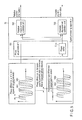
- FIG. 1 is a top plan view showing the configuration of an optical displacement detection system according to an embodiment of the present invention
- FIG. 2 is a cross-sectional view taken along the line I-I showing the optical displacement detection system shown in FIG. 1 ;
- FIG. 3 is a view showing an example of the relationship between a light-receiving surface formed on a first photodetector and an optical image formed on the light-receiving surface;
- FIGS. 4A and 4B are views showing an example of an output signal of four-group light-receiving element arrays of a photodetector
- FIG. 5 is a view to explain the conceptual configuration of a signal processing apparatus according to an embodiment of the present invention.
- FIGS. 6A and 6B are views showing the circuit configuration of a phase shift unit
- FIG. 7 is a view showing the circuit configuration of a modification example of the phase shift unit
- FIG. 8 is a block diagram showing a first configuration of a signal processing apparatus
- FIGS. 9A and 9B are views showing an example of the output characteristic of an in-phase noise removal unit
- FIG. 10 is a graph showing the characteristic of amplitude components Vpp 1 and Vpp 2 ;
- FIG. 11 is a graph showing an example of the characteristic of (Vpp 1 +Vpp 2 ) and (Vpp 1 ⁇ Vpp 2 );
- FIG. 12 is a graph showing the characteristic of the ratio of (Vpp 1 +Vpp 2 ) and (Vpp 1 ⁇ Vpp 2 );
- FIG. 13 is a view showing an example of the output characteristic of an in-phase synthesizer unit
- FIG. 14 is a block diagram showing a second configuration of a signal processing apparatus
- FIG. 15 is a view showing an example of a Lissajous figure generated by a Lissajous generator circuit
- FIG. 16 is a view to explain a relative displacement operation based on a Lissajous figure
- FIG. 17 is a block diagram showing the configuration of a first modification example of a phase adjustment unit
- FIG. 18 is a block diagram showing the configuration of a second modification example of a phase adjustment unit
- FIG. 19 is a block diagram showing the configuration of a third modification example of a phase adjustment unit
- FIG. 20 is a block diagram showing the configuration of a forth modification example of a phase adjustment unit
- FIG. 21 is a block diagram showing the configuration of a modification example for executing a signal addition without phase adjustment
- FIG. 22 is a side view showing an optical signal output device used for a conventional photoelectric detection system
- FIG. 23 is a top plan view showing a scale of a conventional photoelectric detection system.
- FIG. 24 is a view showing an output signal of a photodetector of a conventional photoelectric detection system.
- FIG. 1 is a top plan view showing the configuration of an optical displacement detection system according to an embodiment of the present invention.
- FIG. 2 is a cross-sectional view taken along the line I-I showing the optical displacement detection system shown in FIG. 1 .
- An optical pattern such that any of effective reflectance, effective transmittance and diffraction efficiency gradually increases or decreases in a predetermined section along the displacement direction of a displacement detection target is defined as a “grayscale pattern”.
- An optical pattern such that any of effective reflectance, effective transmittance and diffraction efficiency periodically changes with respect to the displacement direction of a displacement detection target is defined as an “encode pattern”.
- a pattern having optical characteristics combining an encode pattern with a grayscale pattern is defined as a “modulation code pattern”.
- a track formed of any of a grayscale pattern and a modulation code pattern is defined as a “gray track”.
- an optical displacement detection system 10 comprises an optical signal output device including a sensor head 30 and a scale 50 , and a signal processing apparatus 70 .
- One of the foregoing sensor head 30 and scale 50 is connected to a displacement detection target displaceable to a predetermined direction, and the other thereof is connected to a reference surface.
- the displacement direction of a displacement detection target is set as the direction (X-direction) along the x-axis shown in FIG. 1 .
- a sensor head 30 of the optical signal output device includes a light source 31 , first and second photodetectors 32 and 33 .
- a light-receiving surface (provided with first and second photodetectors 32 and 33 ) of the sensor head 30 and the scale 50 are arranged in parallel to face each other.
- the light source 31 includes a light source (e.g., laser diode) and slits 31 a.
- the light source 31 irradiates light beams from the light source to the scale 50 through the slits 31 a.
- the light source 31 is configured to irradiate light beams in two directions through the slits 31 a as can be seen from FIG. 2 .
- a reference number 61 denotes one light beam while a reference number 62 denotes the other light beam.
- the first photodetector 32 has a light-receiving surface, which is formed with four-group light-receiving element arrays.
- Each of light-receiving element arrays has a plurality of light-receiving elements (e.g., photodiode) for converting the light beam 61 emitted to the scale 50 and reflected by the scale 50 into an electric signal.
- the second photodetector 33 has a light-receiving surface, which is formed with four-group light-receiving element arrays.
- Each of light-receiving element arrays has a plurality of light-receiving elements (e.g., photodiode) for converting the light beam 62 emitted to the scale 50 and reflected by the scale 50 into an electric signal.
- the light-receiving element forming each group light-receiving element array is formed having the same spatial period as a spatial period of an optical image (diffraction pattern) formed by each of the first and second photodetectors by a reflected light from the scale 50 .
- FIG. 3 is a view showing an example of the relationship between a light-receiving surface formed on a first photodetector 32 and an optical image formed on the light-receiving surface.
- a second photodetector 33 the same relationship as the first photodetector 32 described below is established.
- the light beam 61 emitted from the light source 31 is reflected by the scale 50 . Then, the reflected light is incident on a light-receiving surface of the first photodetector 32 .
- an optical image 80 having a spatial period pi shown in FIG. 3 is formed on the light-receiving surface of the first photodetector 32 .
- the first photodetector 32 is formed with four-group light-receiving element arrays 321 to 324 at a pitch equivalent to a spatial period pi of the optical image 80 . These light-receiving element arrays 321 to 324 are arranged in a state of being shifted by pi/4 in the spatially periodic direction.
- each light-receiving element In the light-receiving array 321 , each light-receiving element outputs a signal from an output terminal VA 1 . In the light-receiving array 322 , each light-receiving element outputs a signal from an output terminal VB 1 . In the light-receiving array 323 , each light-receiving element outputs a signal from an output terminal VAB 1 . In the light-receiving array 324 , each light-receiving element outputs a signal from an output terminal VBB 1 .
- light-receiving element arrays 321 to 324 each detect a light having a spatial phase difference, which is shifted by a 1 ⁇ 4 period. Therefore, output signals VA 1 , VB 1 , VAB 1 and VBB 1 of each light-receiving element array of the first photodetector 32 are provided a periodic signal which is shifted by an electric angle of 90° (i.e., 1 ⁇ 4 period).
- the scale 50 is formed so that the displacement direction (X-direction in FIG. 1 ) of a displacement target is set as a longitudinal direction.
- a surface facing the sensor head 30 of the scale 50 is formed with a gray track 51 given as a first track pattern and a gray track 52 given as a second track pattern.
- Gray tracks 51 and 52 shown in FIG. 1 are formed of a modulation code pattern only, for example.
- the modulation code pattern of the gray track 51 is formed with a plurality of encode patterns 53 , which have different effective reflectance so that an effective reflectance gradually increases every spatial period ps, along the X-direction of FIG. 1 .
- the modulation code pattern of the gray track 52 is formed with a plurality of encode patterns 53 , which have different effective reflectance so that an effective reflectance gradually decreases every spatial period ps, along the X-direction of FIG. 1 .
- the foregoing gray tracks 51 and 52 are formed, and thereby, the modulation code patterns forming gray tracks 51 and 52 have an optical characteristic such that an effective reflectance is mirror-inverted.
- an optical signal output device will be described below.
- various formation principles are applicable to the formation principle of an optical image formed on each light-receiving surface of first and second photodetectors 32 and 33 .
- the detection principle using a triple lattice configuration is given as a typical example.
- a distance between the light source 31 and the encode pattern 53 on the scale 50 is set as Z 1 .
- a distance between the encode pattern 53 on the scale 50 and each light-receiving surface of first and second photodetectors 32 and 33 is set as Z 2 .
- a pitch in the X-direction of the slits 31 a formed in the light source 31 is set as po.
- the foregoing pi, ps, po, Z 1 , Z 2 and a light wavelength ⁇ of the light source 31 have need to coincide with the condition for forming an optical image using a triple lattice configuration.
- the formation principle of an optical image is not limited to the imaging principle of an optical image using the foregoing triple lattice configuration, but other imaging principle may be used. Therefore, the detailed explanation about the process of determining the foregoing pi, ps, po, Z 1 , Z 2 and a light wavelength ⁇ of the light source 31 is omitted herein.
- the foregoing first and second photodetectors 32 and 33 are formed with four-group light-receiving element arrays with a pitch equivalent to a spatial period pi of an optical pattern.
- Each group is arranged in a state of being shifted by pi/4 along the spatial period direction.
- light-receiving element arrays of each group detect light having a spatial phase difference shifted by 1 ⁇ 4 period with respect to an optical image on the light-receiving surface with a spatial period pi. Therefore, output signals (first periodic signals) VA 1 , VB 1 , VAB 1 and VBB 1 of each light-receiving element array of the first photodetector 32 are each provided as a periodic signal, which is shifted by an electric angle of 90°.
- output signals (second periodic signals) VA 2 , VB 2 , VAB 2 and VBB 2 of each light-receiving element array of the second photodetector 33 are each provided as a periodic signal, which is shifted by an electric angle of 90°.
- the modulation code pattern forming the gray track 51 is formed with the encode pattern 53 to have an optical characteristic such that an effective reflectance gradually increases along the displacement direction of a displacement detection target.
- the modulation code pattern forming the gray track 52 is formed with the encode pattern 53 to have an optical characteristic such that an effective reflectance gradually decreases along the displacement direction of a displacement detection target.
- output signals VA 1 , VB 1 , VAB 1 and VBB 1 of light-receiving element arrays of each group of the first photodetector 32 each increase in its amplitude.
- output signals VA 2 , VB 2 , VAB 2 and VBB 2 of light-receiving element arrays of each group of the second photodetector 33 each decrease in its amplitude.
- periodic signals VA 2 , VB 2 , VAB 2 and VBB 2 having a phase difference shifted by 90° (i.e., 1 ⁇ 4 period) and a characteristic such that amplitude gradually decreases are output from output terminals VA 2 , VB 2 , VAB 2 and VBB 2 of light-receiving element arrays of each group of the second photodetector 33 .
- FIG. 4A shows an example of output signals of four-group light-receiving element arrays of the first photodetector 32 .
- FIG. 4B shows an example of output signals of four-group light-receiving element arrays of the second photodetector 33 .
- the actual output signal of a light-receiving element array contains a direct current (DC) component, which is considerably affected by an optical arrangement of the light source 31 and the scale 50 .
- DC direct current
- VDC 2 each DC component of output signals VA 2 , VB 2 , VAB 2 and VBB 2 is shown as VDC 2 .
- VDC 1 has a characteristic such that the output level gradually increases (simply increases) according to the displacement of a displacement detection target.
- VDC 2 has a characteristic such that the output level gradually decreases (simply decreases) according to the displacement of a displacement detection target.
- the configuration and operation of the optical signal output device are as described above.
- the configuration of gray tracks 51 and 52 is not limited to that shown in FIG. 1 .
- the configuration of gray tracks 51 and 52 is applied to a reflection-type optical signal output device. This device detects reflected light from the scale 50 of light beams 61 and 62 emitted from the light source 31 by means of first and second photodetectors 32 and 33 .
- the foregoing configuration of gray tracks 51 and 52 is applied to a transmission-type optical signal output device. This device detects transmitted light of light beams 61 and 62 emitted to the scale 50 from the light source by means of first and second photodetectors 32 and 33 .
- the foregoing example shows the configuration in which the light source 31 is provided with the slits 31 a having a pitch po.
- This configuration takes the use of the imaging principle of an optical image using the triple lattice configuration into consideration. Therefore, other imaging principles are used; the slits 31 a are not necessarily an essential constituent component.
- FIG. 5 is a view showing the conceptual configuration of a signal processing apparatus according to this embodiment.
- output signals VA 1 and VB 1 having mutually different phase ⁇ are input to the signal processing apparatus 70 as an output signal from the first photodetector 32 .
- output signals VA 2 and VB 2 having mutually different phase ⁇ are input to the signal processing apparatus 70 as an output signal from the second photodetector 33 .
- Output signals VA 1 , VB 1 , VA 2 and VB 2 shown in FIG. 5 are signals sufficiently necessary to detect the displacement of a displacement detection target.
- output signals VAB 1 , VBB 1 , VAB 2 and VBB 2 are input to the signal processing apparatus 70 to remove an in-phase noise.
- output signals VA 1 and VB 1 have a characteristic such that amplitude and DC component gradually increase according to a displacement.
- output signals VA 2 and VB 2 have a characteristic such that amplitude and DC component gradually decrease according to a displacement.
- the amplitude and DC component of signals VA 1 , VB 1 , VA 2 and VB 2 are illustrated as being constant without depending on a displacement.
- the operation of a phase adjustment unit 701 with respect to output signals shown in FIGS. 4A and 4B is almost the same as the output signals shown in FIG. 5 described later.
- the signal processing unit 70 mainly comprises a phase adjustment unit 701 , an absolute displacement operation unit 702 and a relative displacement operation unit 703 .
- the phase adjustment unit 701 has one or more phase shifters.
- the phase shifter simultaneously shifts the phase of one group of periodic signals output from the same photodetector.
- the phase shifter shifts at least one phase of output signals VA 1 and VB 1 of the first photodetector 32 and output signals VA 2 and VB 2 of the second photodetector 33 by a phase difference ⁇ between output signals of the foregoing first and second photodetectors 32 and 33 .
- the phase adjustment unit 701 shown in FIG. 5 has a phase shifter 701 a which shifts the phase of output signals VA 2 and VB 2 of the second photodetector 33 .
- the scale 50 is formed with two-line gray tracks.
- the first and second photodetectors 32 and 33 are configured to independently receive reflected light of a light beam though each gray track.
- a phase shift ⁇ is generated between the following output signals due to a shift in the arrangement between the sensor head 30 and the scale 50 .
- the phase shift ⁇ is generated between the output signal VA 1 of the first photodetector 32 and the output signal VA 2 of the second photodetector 33 and between the output signal VB 1 of the first photodetector 32 and the output signal VB 2 of the second photodetector 33 .
- the phase shift ⁇ is further generated between the output signal VAB 1 of the first photodetector 32 and the output signal VAB 2 of the second photodetector 33 and between the output signal VBB 1 of the first photodetector 32 and the output signal VBB 2 of the second photodetector 33 .
- a big load is given to a processing circuit for detecting an amplitude and phase of an analog periodic signal such as the foregoing output signal of the photodetector. So, an amplitude and phase of a signal obtained by adding and subtracting output signals of a plurality of photodetectors are detected. In this way, output signals of some photodetectors can be collected into one output signal. In this case, this serves to simplify the position detection thereafter.
- phase shifter 701 a of the phase adjustment unit 701 executes the foregoing electric phase adjustment.
- phase adjustment of the second photodetector 33 is performed by generating signals VA 2 ′ and VB 2 ′, which are shifted by ⁇ from the original phase.
- the foregoing signals VA 2 ′ and VB 2 ′ are generated using output signals VA 2 and VB 2 mutually having a ⁇ (90° in FIG. 5 ) phase difference and the following trigonometric function (equation 3).
- the amplitude of output signals of the first photodetector 32 are equal, and also, the amplitude of output signals of the second photodetector 33 are equal.
- the amplitude of output signals of the first photodetector 32 and the amplitude of output signals of the second photodetector 33 are not necessarily equal.
- FIGS. 6A and 6B are the circuit configuration of the phase shifter for executing the foregoing phase adjustment shown in equation (3).
- FIG. 6A shows the circuit configuration for executing a phase adjustment with respect to a phase difference ⁇ of 0° ⁇ 90°.
- This circuit has input terminals VA 2 , VB 2 , VAB 2 and VBB 2 for output signals from the second photodetector 33 . Further, the circuit has variable resistors (four in FIG. 6A ) corresponding to the number of input terminals. These variable resistors are connected in series.
- the input terminal VA 2 is connected to a connection point RA 2 of the variable resistors through a buffer circuit Buf such as a voltage follower.
- Buf such as a voltage follower.
- the input terminal VB 2 is connected to a connection point RB 2 of the variable resistors through a buffer circuit Buf.
- the input terminal VAB 2 is connected to a connection point RAB 2 of the variable resistors through a buffer circuit Buf.
- the input terminal VBB 2 is connected to a connection point RBB 2 of the variable resistors through a buffer circuit Buf.
- an output signal VA 2 ′ having a phase difference of ⁇ with respect to the output signal VA 2 is obtained from the following equation (4).
- output signals VB 2 ′, VAB 2 ′ and VBB 2 ′ are obtained in the manner as above.
- R 1 denotes a resistance between a connection point RA 2 and a switch
- R 2 denotes a resistance between a switch and a connection point RB 2 .
- R 1 /(R 1 +R 2 ) corresponds to a of equation (3)
- R 2 /(R 1 +R 2 ) corresponds to b of equation (3)
- phase adjustment range is widened. For example, two circuits are combined, and thereby, phase adjustment is possible in a range from 0 to 180°.
- an input change circuit for changing the input to the phase shifter shown in FIG. 6A or an output change circuit for changing the output from the phase shifter is combined with the circuit of the phase shifter shown in FIG. 6A . In this way, phase adjustment is possible in all angle, that is, in a range from 0 to 360°.
- phase of output VAB 2 ′ shifts by 180° with respect to outputs VAB 2 ′
- a phase of output VBB 2 ′ shifts by 180° with respect to outputs VBB 2 ′.
- a portion shown by the broken line is deleted from the circuit shown in FIG. 6A .
- each phase of signals VA 2 ′ and VB 2 ′ may be inverted by 180° using an inverter so that signals VBB 2 ′ and VBB 2 ′ are generated.
- a phase shift is carried out by generating the sum signal through resistors; in this case, a circuit using an operational amplifier may be used.
- the detailed configuration of the circuit is shown in FIG. 6B .
- the output VA 2 ′ is obtained from the following equation (5).
- phase shift circuit is combined several, or input/output signals are changed or a combination with a signal inversion circuit is made. In this way, it is possible to realize a phase adjustment circuit, which is capable of performing phase adjustment in a desired angle range.
- FIG. 6A or 6 B has the configuration of analogy changing a resistance.
- the resistance may be digitally changed to perform phase adjustment.
- FIG. 7 shows the circuit configuration for realizing the foregoing digital phase adjustment. According to the configuration of FIG. 7 , a signal group having the most preferable phase is selected from a plurality of phase signals.
- FIG. 7 shows the circuit configuration for performing phase adjustment with respect to a phase difference ⁇ in a range of 0° ⁇ 90°. According to the foregoing configuration of FIG. 7 , phase adjustment is automatically performed.
- phase shifter 701 a so long as the phase of a group of periodic signals output from the same photodetector is simultaneously shifted by a phase difference ⁇ .
- the following configuration may be employed. Specifically, both phases of output signals VA 1 , VB 1 , VAB 1 and VBB 1 of the first photodetector 32 and phases of output signals VA 2 , VB 2 , VAB 2 and VBB 2 of the second photodetector 33 are shifted to offset a phase difference ⁇ .
- a signal to be executed a phase shift may be changed between output signals VA 1 , VB 1 , VAB 1 and VBB 1 of the first photodetector 32 and output signals VA 2 , VB 2 , VAB 2 and VBB 2 of the second photodetector 33 .
- the phase shifter 701 a may be realized using an operation circuit.
- the absolute displacement operation unit 702 calculates an absolute displacement of a displacement detection target based on the output signal of the first photodetector 32 and the output signal of the second photodetector 33 in which a phase is shifted by the phase shifter 701 a.
- the relative displacement operation unit calculates a relative displacement of a displacement detection target based on the output signal of the first photodetector 32 and the output signal of the second photodetector 33 in which a phase is shifted by the phase shifter 701 a.
- FIG. 8 is a block diagram showing a first configuration of a signal processing apparatus 70 .
- the signal processing apparatus 70 shown in FIG. 8 includes in-phase noise removal units 704 a, 704 b, a phase adjustment unit 701 , an amplitude component differential calculation unit 705 , an in-phase synthesizer unit 706 , an absolute displacement operation unit 702 and a relative displacement operation unit 703 .
- the amplitude component differential calculation unit 705 , in-phase synthesizer unit 706 , absolute displacement operation unit 702 and relative displacement operation unit 703 function as an example of a “signal processing unit”.
- FIG. 9A shows an output signal of the in-phase noise removal unit 704 a
- FIG. 9B shows an output signal of the in-phase noise removal unit 704 b.
- the in-phase noise removal unit 704 a an influence of offset, noise and DC components contained in the output signal of the first photodetector 32 is cancelled.
- output signals Va 1 and Vb 1 having a phase difference ⁇ (90° in this embodiment) are obtained.
- an influence of offset, noise and DC components contained in the output signal of the second photodetector 33 is cancelled.
- output signals Va 2 and Vb 2 having a phase difference ⁇ (90° in this embodiment) are obtained.
- output signals VA 1 , VB 1 , VA 2 and VB 2 only may be input with respect to signals from an optical signal output device.
- the phase adjustment unit 701 shifts the phase of at least one (output signals Va 2 , Vb 2 only in FIG. 8 ) of output signals Va 1 and Vb 1 of the in-phase noise removal unit 704 a and output signals Va 2 and Vb 2 of the in-phase noise removal unit 704 b by ⁇ using the phase shifter 701 a.
- phase difference ⁇ between output signals Va 1 , Vb 1 and Va 2 , Vb 2 that is, between output signals VA 1 , VB 1 , VAB 1 , VBB 1 of the first photodetector 32 and output signals VA 2 , VB 2 , VAB 2 , VBB 2 of the second photodetector 33 is detected by means of a phase difference detection circuit, for example.
- This phase difference detection circuit is provided independently from the signal processing apparatus 70 .
- the foregoing phase difference ⁇ is detectable according to an amplitude change before and after addition of signals by the amplitude component differential calculation unit 705 and the in-phase synthesizer unit 706 , which will be described later.
- the following method is given as a method of detecting a phase difference between a plurality of periodic signals having the same period and a phase difference with respect to a periodic signal having a specified phase. For example, a phase difference between points capable of specifying a phase of the peak of a waveform captured by an oscilloscope is detected. Moreover, the phase difference is calculated using an elliptic shape of a Lissajous waveform generated by two sine wave signals. According to the elliptic Lissajous waveform, a phase difference between two signals is calculated from the amplitude of two signals and a tilted angle with respect to coordinate axes corresponding to long- and short-axis of an ellipse.
- a phase difference between original two signals is calculated from a phase shift amount in which the amplitude of the sum signal becomes the maximum or the minimum.
- the following methods are given as a method of giving a phase shift amount.
- One is a method of changing the phase shift amount of one of a couple of two signals within a range of 180° or 360°.
- the other is a method of giving a well-known phase shift amount having different value to one of several couples of two signals.
- the former method of changing the phase shift amount of one of a couple of two signals has the following methods.
- One is a method of sweeping a predetermined range in a predetermined step to detect a phase difference.
- the other is a method of gradually approaching a phase difference to a desired phase difference, that is, the optimal value using an optimization process.
- the amplitude component differential calculation unit 705 extracts a amplitude component Vpp 1 of output signals Va 1 and Vb 1 of the phase adjustment unit 701 and a amplitude component Vpp 2 (same as output signals Va 2 and Vb 2 ) of output signals Va 2 ′ and Vb 2 ′ thereof. Then, the unit 705 calculates the sum of the amplitude components Vpp 1 and Vpp 2 and the difference between the amplitude components Vpp 1 and Vpp 2 .
- FIG. 10 shows each of characteristics of the foregoing amplitude components Vpp 1 and Vpp 2 .
- the modulation code pattern of the gray track 51 has an optical characteristic such that an effective reflectance gradually increases along the X-direction of FIG. 1 .
- the modulation code pattern of the gray track 52 has an optical characteristic such that an effective reflectance gradually decreases along the X-direction of FIG. 1 .
- the amplitude component Vpp 1 has a simply increasing characteristic 104 with respect to a displacement x as can be seen from FIG. 10 .
- the amplitude component Vpp 2 output from the second photodetector 33 has a simply decreasing characteristic 105 with respect to a displacement x as can be seen from FIG. 10 .
- the foregoing amplitude components Vpp 1 and Vpp 2 are defined by the following equations (8) and (9).
- Vpp 1 a ⁇ x (8)
- Vpp 2 ⁇ a ⁇ x ( x ⁇ L gray) (9)
- “Lgray” denotes a length of a predetermined section that an effective reflectance of the scale 50 gradually increases or decreases.
- “a” denotes a change (i.e., gradient of Vpp 1 shown in FIG. 10 ) of the Vpp 1 when a displacement detection target displaces by a unit distance.
- Vppmax is set as the maximum amplitude of a signal of each of first and second photodetectors 32 and 33
- Vpp 1+ Vpp 2 a ⁇ L gray (11)
- Vpp 1 ⁇ Vpp 2 2 a ⁇ x ⁇ a ⁇ L gray (12)
- Equation (11) The characteristic of equation (11) is shown by a characteristic line 106 in FIG. 11
- the characteristic of equation (12) is shown by a characteristic line 107 in FIG. 11 .
- each calculation shown by equations (11) and (12) is correctly carried out.
- the absolute displacement operation unit 702 executes an operation for calculating an absolute displacement x using the sum (Vpp 1 +Vpp 2 ) and difference (Vpp 1 ⁇ Vpp 2 ) of the amplitude component operated by the amplitude component differential calculation unit 705 .
- the foregoing unit 702 executes a calculation shown by the following equation (13). ( Vpp 1+ Vpp 2)/( Vpp 1 ⁇ Vpp 2) (13)
- equation (14) It is very easy to make a conversion from equation (13) for calculating the absolute displacement x into equation (14).
- the calculation of equation (14) may not necessarily be carried out by the absolute displacement operation unit 702 .
- a conversion by equation (14) may be carried out by a host computer (not shown), which is located at the after-stage of the signal processing apparatus 70 .
- amplitude components Vpp 1 and Vpp 2 are used as a method of operating an absolute displacement.
- Amplitude components of output signals of first and second photodetectors 32 and 33 that is, Vpp 1 and Vpp 2 may have the following relationship. Namely, the sign of increase and decrease with a displacement is reverse, and the increase and decrease absolute value is equal and further, the sum is constant.
- the foregoing equations (11) to (14) may be realized using DC level signals of FIGS. 4A and 4B , that is, VDC 1 and VDC 2 .
- the output signal from the light source and the sensibility characteristic of photodetectors change due to an age-based change of an optical displacement detection system or a change of environment temperature. Moreover, even if the output signal from the light source and the sensibility characteristic of photodetectors are unchanged, the quantity of light detected by a photodetector changes due to a factor of an attaching shakiness of a sensor head and a scale. In general, the output amplitude and the sum/difference components from a sensor head considerably changes due to the foregoing change factors. For example, as shown in FIGS.
- the characteristic changes from the solid line 104 to the broken line 104 ′, and changes from the solid line 105 to the broken line 105 ′, and further, changes from the solid line 106 to the broken line 106 ′, and further, changes from the solid line 107 to the broken line 107 ′.
- the sum/difference of Vpp 1 and Vpp 2 are calculated, and further, a ratio of the sum/difference of Vpp 1 and Vpp 2 is calculated.
- a displacement which cancels changing components, that is, the gradient “a” and the maximum amplitude Vppmax, from the foregoing equation (16).
- the characteristic of equation (15) is shown by the solid line 108 in FIG. 12 .
- the characteristic shown in FIG. 12 does not depend on a gradient “a” and the maximum amplitude Vppmax. Therefore, it is possible to calculate an absolute displacement x without calculating the foregoing gradient “a” and maximum amplitude Vppmax. As a result, this serves to dispense the initial setting of a sensor head and a scale in order to calculate an absolute displacement x.
- Signals Va and Vb having a phase difference of 90° (i.e., 1 ⁇ 4 period) shown in FIG. 13 are obtained from the in-phase synthesizer unit 706 .
- the relative displacement operation unit 703 converts a displacement into angle information based on a phase angle of signals Va and Vb obtained by the in-phase synthesizer unit 706 . Then, the unit 703 makes a comparison between the angle information and the previous calculation result to calculate a displacement corresponding to a resolving power. When executing the foregoing processing, the unit 703 may directly calculate the amplitude value to convert it into angle information so that a displacement is calculated. Or, the unit 703 may calculate a displacement using a so-called ROM table reference method.
- the optical signal output device is provided with two photodetectors. Absolute displacement and relative displacement of a displacement detection target are detected using two signals output from the foregoing photodetectors. These signals have the following relationship that a sign of increase/decrease of an amplitude component with displacement is reverse, and the absolute value of the increase/decrease is equal, and further, the sum is constant. In this way, it is possible to keep a resolving power at high level in both of absolute and relative displacement detections and to realize improvement of detection sensibility of an absolute position and enlargement of a detection range.
- the phase of at least output signal of one photodetector is shifted by a phase difference ⁇ . In this way, an influence by an error when a displacement is detected is reduced, and thereby, it is possible to stably and precisely detect a displacement.
- FIG. 14 is a block diagram showing a second configuration according to a modification example of a signal processing apparatus 70 .
- the signal processing apparatus 70 shown in FIG. 14 includes in-phase noise removal units 704 a, 704 b, a phase adjustment unit 701 , a Lissajous generator circuit 707 , an absolute displacement operation unit 702 , interpolation circuits 708 a, 708 b, and a relative displacement operation unit 703 .
- an absolute displacement and a relative displacement are detected based on a Lissajous figure.
- the Lissajous generator circuit 707 generates a Lissajous figure from each of output signals Va 1 , Vb 1 , Va 2 ′ and Vb 2 ′ output from the phase adjustment unit 701 .
- the absolute displacement operation unit 702 of FIG. 14 executes a calculation shown by the following equation (18) with respect to radiuses r 1 and r 2 of Lissajous figures L 1 and L 2 generated by the Lissajous generator circuit 707 . In this way, the unit 702 calculates an absolute displacement. (r 1 ⁇ r 2 )/(r 1 +r 2 ) (18)
- the absolute displacement operation unit 702 calculates a rough absolute position. Thereafter, the foregoing rough absolute position may be combined with a relative position obtained by the relative displacement operation unit 703 to obtain a high precious absolute position. Moreover, for example, a simple circuit element such as a comparator detects signals to make a comparison determination. Of course, an absolute position may be calculated directly based on an analog value.
- the foregoing angle information is finely operated, and thereby, it is possible to detect a fine displacement compared with a spatial period ps.
- analog output signals from the Lissajous generator circuit 707 are digitized to generate address data. Then, the circuit 707 refers to an angle information table recorded in each interpolation circuit based on the foregoing address data to execute an interpolation processing. Moreover, depending on a resolving power, a simple circuit element such as a comparator detects a signal directly using an analog value to calculate a displacement.
- the relative displacement operation unit 703 operates angle information ⁇ 1 and ⁇ 2 operated by the interpolation circuits 708 a and 708 b to remove an error component.
- the error component serves to operate the difference between the removed current angle information and angle information acquired at the previous timing.
- a processing for “removing an error component” is not limited to a processing for taking an average value of angle information output from interpolation circuits 708 a and 708 b.
- the following three examples of processing are included as the foregoing processing for “removing an error component”.
- a change ⁇ of the angle information operated by the relative displacement operation unit 703 is equivalent to a displacement in a spatial period ps.
- the relative displacement xp shown in the foregoing equation (21) is able to be calculated by angle information only from any of interpolation circuits 708 a and 708 b.
- a relative displacement is calculated from one angle information only, a calculation error of a relative displacement becomes considerably large when amplitude is small.
- the relative displacement is calculated using angle information from two interpolation circuits 708 a and 708 b. In this case, if the amplitude of one signal is small, the amplitude of the other signal becomes large. Therefore, an influence by a calculation error is cancelled; as a result, it is possible to stably and high precisely operate a relative position.
- the Lissajous generator circuit 707 adds in-phase signals of output signals Va 1 , Vb 1 , Va 2 ′ and Vb 2 ′ from the phase adjustment unit 701 .
- 1 ⁇ 4 period phase difference signals Va and Vb having a fixed amplitude with respect to a displacement x are obtained.
- the signal Va is set as a cosine component and the signal Vb is set as a sine component to generate a Lissajous figure
- a circular locus drawn by a fixed radius shown in FIG. 16 is obtained.
- a relative displacement xp is calculated from a change of a phase angle ⁇ on the circumference. According to the foregoing operation, it is possible to stably and high precisely operate a relative position.
- FIG. 17 is a block diagram showing the configuration of a phase adjustment unit 701 according to a first modification example.
- the phase adjustment unit 701 is provided with a phase difference detector 701 b in addition to the configuration shown in FIG. 5 .
- the phase difference detector 701 b detects a phase difference ⁇ between mutually corresponding signals (having a specific phase, i.e., output signals VA 1 and VA 2 ) of output signal VA 1 , VB 1 , VAB 1 , VBB 1 of a first photodetector 32 and output signal VA 2 , VB 2 , VAB 2 , VBB 2 of a second photodetector 33 . Then, the detector 701 b outputs the detected phase difference ⁇ to a phase shifter 701 a.
- the phase shifter 701 a shifts each phase of output signal VA 2 , VB 2 , VAB 2 , VBB 2 of the second photodetector 33 by the phase difference ⁇ detected by the phase difference detector 701 b.
- each phase of output signal VA 2 , VB 2 , VAB 2 , VBB 2 of the second photodetector 33 is shifted; in this case, each phase of output signals VA 1 , VB 1 , VAB 1 , VBB 1 of the first photodetector 32 may be shifted. Moreover, each phase of both photodetectors may be shifted.
- a phase difference between a couple of output signals comprising output signals VA 1 and VA 2 ; in this case, all phase differences of four couples of output signals may be detected. In this case, an average value of the foregoing phase differences of four couples of output signals is input to the phase shifter 701 a.
- phase adjustment can be carried out in the signal processing apparatus 70 .
- a phase is detectable as the necessity arises; therefore, adjustment is carried out based on the newest detection result.
- a phase is always detected, and thereby, real-time phase adjustment is possible.
- FIG. 18 is a block diagram showing the configuration of a phase adjustment unit 701 according to a second modification example.
- the phase adjustment unit 701 is provided with a selector 701 c in addition to the configuration shown in FIG. 17 .
- the phase difference ⁇ detected by the phase difference detector 701 b is input to the selector 701 c and the phase shifter 701 a.
- the selector 701 c rearranges output signal VA 2 , VB 2 , VAB 2 , and VBB 2 of the second photodetector 33 in accordance with the phase difference ⁇ detected by the phase difference detector 701 b. Then, the selector 701 c outputs rearranged signals VA 2 , VB 2 , VAB 2 , and VBB 2 to the phase shifter 701 a.
- the phase shifter 701 a shifts each phase of rearranged signals VA 2 A, VA 2 B, VB 2 A and VB 2 B. Then, the phase shifter 701 a outputs phase-shifted signals VA 2 A, VA 2 B, VB 2 A and VB 2 B as outputs VA 2 A′, VA 2 B′, VB 2 A′ and VB 2 B′.
- the foregoing rearrangement by the selector 701 c is made so that a phase shift amount by the phase shifter 701 a becomes small.
- output signals VA 2 , VB 2 , VAB 2 , and VBB 2 each have a phase difference by ⁇ (90° (1 ⁇ 4 period) in this embodiment).
- the selector 701 c rearranges signals, and thereby, a phase shift at a unit of ⁇ is performed before signals are input to the phase shifter 701 a. In this way, the phase shift amount of the phase shifter 701 a is reduced.
- FIG. 19 is a block diagram showing the configuration of a phase adjustment unit 701 according to a third modification example.
- the phase adjustment unit 701 is provided with an amplitude center difference corrector 701 d, an amplitude difference detector 701 e and an amplitude controller 701 f in addition to the configuration shown in FIG. 18 .
- the amplitude center difference corrector 701 d has an amplitude center difference detector 7011 d.
- the amplitude center difference detector 7011 d detects a difference from a predetermined value of a DC level of the each of amplitude center of output signals VA 1 , VB 1 , VAB 1 , VBB 1 of the first photodetector 32 and output signal VA 2 , VB 2 , VAB 2 , VBB 2 of the second photodetector 33 .
- the detector 7011 d detects a difference between a DC level of the amplitude center of output signals VA 1 , VB 1 , VAB 1 , VBB 1 of the first photodetector 32 and a DC level of the amplitude center of output signal VA 2 , VB 2 , VAB 2 , VBB 2 of the second photodetector 33 .
- the detector 7011 d corrects any one DC level of the amplitude center of output signals VA 1 , VB 1 , VAB 1 , VBB 1 and output signal VA 2 , VB 2 , VAB 2 , VBB 2 to compensate (offset) the difference from a predetermined value of a DC level of the amplitude center detected by the detector 7011 d or the difference between DC levels of the amplitude center.
- the amplitude difference detector 701 e detects an amplitude difference between output signal VA 2 , VB 2 , VAB 2 and VBB 2 of the second photodetector 33 .
- the amplitude controller 701 f has amplitude control circuits corresponding to the number of output signals of the phase shifter 701 a (four output signals, that is, VA 2 ′, VB 2 ′, VAB 2 ′, VBB 2 ′ in FIG. 19 ). Then, the controller 701 f performs amplitude control of output signals VA 2 ′, VB 2 ′, VAB 2 ′ and VBB 2 ′ in accordance with the amplitude difference detected by the amplitude difference detector 701 e.
- the amplitude control circuit has amplifier circuits, for example.
- the amplitude control is performed to adjust the amplitude of each output signal, and to set a desired amplitude and amplitude ratio.
- an influence of the original signal of first and second photodetector 32 and 33 to signal information such as the amplitude and phase of the added/subtracted signal is set to a predetermined ratio. Therefore, it is possible to avoid position detection depending on the output of one photodetector only, and thus, to perform a high-precision position detection.
- the amplitude difference detector 701 e and the amplitude controller 701 f are provided in the phase adjustment unit 701 .
- the foregoing amplitude difference detector 701 e and amplitude controller 701 f may be provided in the after-stage of the phase adjustment unit 701 .
- the amplitude control is carried out with respect to output signals of the phase shifter 701 a.
- the foregoing amplitude difference detector 701 e and amplitude controller 701 f may be provided in the pre-stage of the phase adjustment unit 701 to carry out amplitude adjustment before phase shift.
- FIG. 20 is a block diagram showing the configuration of a phase adjustment unit 701 according to a fourth modification example.
- the phase adjustment unit 701 is provided with an offset detector 701 g, offset correctors 701 i and 701 h in addition to the configuration shown in FIG. 18 .
- the offset detector 701 g detects amounts of offsets with respect to a reference voltage of output signals VA 1 , VB 1 , VAB 1 and VBB 1 of the first photodetector 32 and output signals VA 2 ′, VB 2 ′, VAB 2 ′ and VBB 2 ′ of the phase shifter 701 a. Or, the offset detector 701 g detects amounts of offsets of output signals VA 2 ′, VB 2 ′, VAB 2 ′ and VBB 2 ′ of the phase shifter 701 a with respect to output signals VA 1 , VB 1 , VAB 1 and VBB 1 of the first photodetector 32 .
- the foregoing offset correctors 701 i and 701 h corrects offsets of at least any one of output signals VA 1 , VB 1 , VAB 1 and VBB 1 of the first photodetector 32 and output signals VA 2 ′, VB 2 ′, VAB 2 ′ and VBB 2 ′ of the phase shifter 701 a to dispense the offsets detected by the offset detector 701 g.
- the foregoing offset correction is made according to a level shift.
- FIG. 20 shows an example in which offset correction of both of the photodetector 32 and the phase shifter 701 a.
- the phase adjustment unit 701 is provided with the offset detector 701 g, offset correctors 701 i and 701 h.
- the offset detector 701 g, offset correctors 701 i and 701 h may be located at the after-stage of the phase adjustment unit 701 .
- an offset correction is carried out with respect to output signals of the phase shifter 701 a.
- the foregoing offset detector 701 g, offset correctors 701 i and 701 h may be located at the pre-stage of the phase adjustment unit 701 to execute an offset correction before phase shift.
- the amplitude control described in FIG. 19 and the offset correction described in FIG. 20 may be performed in combination with each other.
- the foregoing amplitude control and offset correction may be carried out simultaneously and one of them may be carried out in advance.
- phase adjustments for example, even if a phase difference shifts by about 5°, the amplitude error occurs about 0.5% only.
- a phase has no need to fully coincide between output signals of the first photodetector 32 and output signals of the second photodetector 33 .
- a couple of signals having almost no phase difference may be selected from a plurality of candidates.
- FIG. 21 is a block diagram showing the configuration of the foregoing modification example.
- a phase adjustment unit 701 includes various circuits corresponding to the number of input signals (eight, that is, output signals VA 1 , VB 1 , VAB 1 , VBB 1 of a first photodetector and output signals VA 2 , VB 2 , VAB 2 , VBB 2 of a second photodetector in FIG. 21 ).
- the unit 701 includes buffer circuits Buf, amplitude difference detection circuits 801 a, 801 b, a gain instruction circuit 802 , amplitude control circuits 803 a, 803 b, and switch circuits 804 .
- the unit 701 includes buffer circuits Buf, which is connected between the switch circuit 804 and amplitude control circuits 803 a, 803 b, a phase difference detector 805 , a connection change operator 806 , a switch drive circuit 807 and adder circuits 808 .
- the amplitude difference detection circuit 801 a detects an amplitude difference between output signals VA 1 , VB 1 , VAB 1 and VBB 1 of a first photodetector 32 . Moreover, the amplitude difference detection circuit 801 b detects an amplitude difference between output signals VA 2 , VB 2 , VAB 2 and VBB 2 of a second photodetector 33 .
- the gain instruction circuit 802 instructs a gain value of each of output signals VA 1 , VB 1 , VAB 1 and VBB 1 of the first photodetector 32 to the amplitude control circuit 803 a. In this case, the circuit 802 gives instructions to compensate (dispense) the amplitude difference between output signals VA 1 , VB 1 , VAB 1 and VBB 1 of the first photodetector 32 detected by the amplitude difference detection circuit 801 a. Moreover, the gain instruction circuit 802 instructs a gain value of each of output signals VA 2 , VB 2 , VAB 2 and VBB 2 of the second photodetector 33 to the amplitude control circuit 803 b. In this case, the circuit 802 gives instructions to compensate the amplitude difference between output signals VA 2 , VB 2 , VAB 2 and VBB 2 of the second photodetector 33 detected by the amplitude difference detection circuit 801 b.
- signals are only rearranged without carrying out phase shift to add signals. For this reason, if there is a large amplitude difference between output signals VA 1 , VB 1 , VAB 1 and VBB 1 of the first photodetector 32 or between output signals VA 2 , VB 2 , VAB 2 and VBB 2 of the second photodetector 33 , the correct addition result is not obtained.
- the foregoing amplitude control circuits 803 a and 803 b compensates the amplitude difference between output signals VA 1 , VB 1 , VAB 1 and VBB 1 of the first photodetector 32 and between output signals VA 2 , VB 2 , VAB 2 and VBB 2 of the second photodetector 33 . In this way, if a phase difference ⁇ is small, only rearrangement is carried out to execute signal addition, and thereby, it is possible to obtain a correct addition result.
- the switch circuit 804 has switches (four in FIG. 21 ) same as the number of output signals of the second photodetector 33 . These switches are configured to select any of amplitude-controlled output signals VA 2 , VB 2 , VAB 2 and VBB 2 of the second photodetector 33 output from the amplitude control circuit 803 b and to output the selected signals to the adder circuits 808 .
- the phase difference detector 805 detects a phase difference ⁇ between output signals VA 1 , VB 1 , VAB 1 and VBB 1 of the first photodetector 32 and output signals VA 2 , VB 2 , VAB 2 and VBB 2 of the second photodetector 33 . Then, the detector 805 outputs a control signal to the connection change operation unit 806 if the detected phase difference ⁇ is less than a predetermined value (e.g., 5°).
- a predetermined value e.g., 5°
- the connection change operating unit 806 sends a switch change instruction to the switch drive circuit 807 .
- This switch change operation is carried out in the following manner. Specifically, the amplitude-controlled output signal VA 1 of the first photodetector 32 and an amplitude-controlled output signal of the second photodetector 33 having a phase approximately equal to the output signal VA 1 are input to the same adder circuit 808 .
- the amplitude-controlled output signal VB 1 of the first photodetector 32 and an amplitude-controlled output signal of the second photodetector 33 having a phase approximately equal to the output signal VB 1 are input to the same adder circuit 808 .
- the amplitude-controlled output signal VAB 1 of the first photodetector 32 and an amplitude-controlled output signal of the second photodetector 33 having a phase approximately equal to the output signal VAB 1 are input to the same adder circuit 808 .
- the amplitude-controlled output signal VBB 1 of the first photodetector 32 and an amplitude-controlled output signal of the second photodetector 33 having a phase approximately equal to the output signal VBB 1 are input to the same adder circuit 808 .
- the switch drive circuit 807 changes a connected between four switches according to the instructions from the connection change operating unit 806 .
- the adder circuit 808 adds an amplitude-controlled output signal of the first photodetector 32 and an amplitude-controlled and rearranged output signal of the second photodetector 33 .
- the configuration shown in FIG. 1 shows the configuration used for a relative displacement operation of FIG. 8 .
- the adder circuit 808 of FIG. 21 corresponds to the in-phase synthesizer unit 706 of FIG. 8 .
- output signals having the following relationship are selected from output signals of first and second photodetectors, and then, the selected signal are added and subtracted.
- a sign of increase/decrease of an amplitude component with displacement is reverse, and the absolute value of the foregoing increase/decrease is equal, and further, the sum is constant.
- signals having the foregoing relationship are selected from output signals of first and second photodetectors, and then, input to the same adder circuit 808 and a subtractor circuit (not shown). In this way, the configuration shown in FIG. 21 is applicable to an absolute displacement operation.
Abstract
Description
pi=ps·(Z1+Z2)/Z1 (1)
po=ps·(Z1+Z2)/Z2 (2)
acos A+b sin A=√{square root over (a2 +b 2)} sin(A+Δ)
Δ=tan−1(a/b) (3)
where, “a” and “b” are coefficients, and A corresponds to a displacement of a displacement detection target.
Va1=VA1−VAB1
Vb1=VB1−VBB1 (6)
Va2=VA2−VAB2
Vb2=VB2−VBB2 (7)
Vpp1=a·x (8)
Vpp2=−a·x (x−Lgray) (9)
a=Vppmax/Lgray (10)
Vpp1+Vpp2=a·Lgray (11)
Vpp1−Vpp2=2a·x−a·Lgray (12)
(Vpp1+Vpp2)/(Vpp1−Vpp2) (13)
x=α·(Vpp1−Vpp2)/(Vpp1+Vpp2)+β (14)
(Vpp1−Vpp2)/(Vpp1+Vpp2)=2/Lgray·x−1 (15)
x=Lgray·((Vpp1−Vpp2)/(Vpp1+Vpp2)+1)/2 (16)
Va=Va1+Va2′
Vb=Vb1+Vb2′ (17)
(r1−r2)/(r1+r2) (18)
x=α·(r1−r2)/(r1+r2)+β (19)
(r1−r2)/rmax (20)
xp=ps·θ/n (21)
Claims (11)
Applications Claiming Priority (2)
| Application Number | Priority Date | Filing Date | Title |
|---|---|---|---|
| JP2009295977A JP5439163B2 (en) | 2009-12-25 | 2009-12-25 | Signal processing device for optical signal output device and optical displacement detection device |
| JP2009-295977 | 2009-12-25 |
Publications (2)
| Publication Number | Publication Date |
|---|---|
| US20110157578A1 US20110157578A1 (en) | 2011-06-30 |
| US8330943B2 true US8330943B2 (en) | 2012-12-11 |
Family
ID=44187157
Family Applications (1)
| Application Number | Title | Priority Date | Filing Date |
|---|---|---|---|
| US12/976,349 Active 2031-06-14 US8330943B2 (en) | 2009-12-25 | 2010-12-22 | Signal processing apparatus used for optical signal output device and optical displacement detection system |
Country Status (2)
| Country | Link |
|---|---|
| US (1) | US8330943B2 (en) |
| JP (1) | JP5439163B2 (en) |
Cited By (1)
| Publication number | Priority date | Publication date | Assignee | Title |
|---|---|---|---|---|
| US20120085897A1 (en) * | 2010-10-08 | 2012-04-12 | Mitutoyo Corporation | Encoder |
Families Citing this family (2)
| Publication number | Priority date | Publication date | Assignee | Title |
|---|---|---|---|---|
| JP5701496B2 (en) * | 2009-11-20 | 2015-04-15 | オリンパス株式会社 | Signal processing device for optical signal output device and optical displacement detection device |
| DE102017205631A1 (en) * | 2017-04-03 | 2018-10-04 | Robert Bosch Gmbh | LiDAR system and method for determining a system state of a LiDAR system |
Citations (2)
| Publication number | Priority date | Publication date | Assignee | Title |
|---|---|---|---|---|
| JPS4878959A (en) * | 1972-01-22 | 1973-10-23 | ||
| US7499150B2 (en) * | 2002-04-15 | 2009-03-03 | Robert Bosch Company Limited | Distance measurement device |
Family Cites Families (6)
| Publication number | Priority date | Publication date | Assignee | Title |
|---|---|---|---|---|
| JP2571096B2 (en) * | 1988-04-18 | 1997-01-16 | ファナック株式会社 | Encoder |
| DE10201496A1 (en) * | 2002-01-17 | 2003-07-31 | Heidenhain Gmbh Dr Johannes | Scale and position measuring device for absolute position determination |
| JP4750407B2 (en) * | 2004-12-15 | 2011-08-17 | キヤノン株式会社 | Optical encoder |
| JP4632423B2 (en) * | 2005-01-12 | 2011-02-16 | キヤノン株式会社 | POSITION CONTROL DEVICE, POSITION CONTROL METHOD, AND OPTICAL DEVICE |
| JP2007033100A (en) * | 2005-07-25 | 2007-02-08 | Pulstec Industrial Co Ltd | Optical position detection apparatus |
| JP2008116229A (en) * | 2006-11-01 | 2008-05-22 | Koyo Electronics Ind Co Ltd | Incremental type rotary encoder |
-
2009
- 2009-12-25 JP JP2009295977A patent/JP5439163B2/en active Active
-
2010
- 2010-12-22 US US12/976,349 patent/US8330943B2/en active Active
Patent Citations (2)
| Publication number | Priority date | Publication date | Assignee | Title |
|---|---|---|---|---|
| JPS4878959A (en) * | 1972-01-22 | 1973-10-23 | ||
| US7499150B2 (en) * | 2002-04-15 | 2009-03-03 | Robert Bosch Company Limited | Distance measurement device |
Cited By (2)
| Publication number | Priority date | Publication date | Assignee | Title |
|---|---|---|---|---|
| US20120085897A1 (en) * | 2010-10-08 | 2012-04-12 | Mitutoyo Corporation | Encoder |
| US8729458B2 (en) * | 2010-10-08 | 2014-05-20 | Mitutoyo Corporation | Encoder |
Also Published As
| Publication number | Publication date |
|---|---|
| JP2011137643A (en) | 2011-07-14 |
| US20110157578A1 (en) | 2011-06-30 |
| JP5439163B2 (en) | 2014-03-12 |
Similar Documents
| Publication | Publication Date | Title |
|---|---|---|
| US10540559B2 (en) | Position detection apparatus, lens apparatus, image pickup system, machine tool apparatus, position detection method, and non-transitory computer-readable storage medium which are capable of detecting abnormality | |
| EP2511666B1 (en) | Encoder | |
| JP6400036B2 (en) | Position detection device, machine tool, and exposure device | |
| US9417101B2 (en) | Optical encoder with a scale that has fine and coarse pitch patterns | |
| JP5479255B2 (en) | Optical encoder | |
| US11073410B2 (en) | Position measuring device | |
| US10831035B2 (en) | Optical encoder | |
| US8993954B2 (en) | Optical encoder having a high resolution detection mode to detect a fine pitch pattern and a low resolution detection mode to detect a coarse pitch pattern | |
| US8330943B2 (en) | Signal processing apparatus used for optical signal output device and optical displacement detection system | |
| JP5701496B2 (en) | Signal processing device for optical signal output device and optical displacement detection device | |
| US9383230B2 (en) | Position detection apparatus, lens apparatus, image pickup system, machine tool apparatus, position detection method, and non-transitory computer-readable storage medium | |
| JP6373457B1 (en) | Encoder and imaging apparatus using the same | |
| JP3808192B2 (en) | Movement amount measuring apparatus and movement amount measuring method | |
| JP2017067742A (en) | Interferometer and displacement-amount measurement device | |
| JP2016014612A (en) | Encoder | |
| JPH02176419A (en) | Optical encoder | |
| JP2017067785A (en) | Displacement-amount measurement device | |
| JPH0416713A (en) | Optical linear encoder |
Legal Events
| Date | Code | Title | Description |
|---|---|---|---|
| AS | Assignment |
Owner name: OLYMPUS CORPORATION, JAPAN Free format text: ASSIGNMENT OF ASSIGNORS INTEREST;ASSIGNORS:HANE, JUN;FUJITA, HIROMASA;YAMAMOTO, EIJI;REEL/FRAME:025765/0283 Effective date: 20101216 |
|
| FEPP | Fee payment procedure |
Free format text: PAYOR NUMBER ASSIGNED (ORIGINAL EVENT CODE: ASPN); ENTITY STATUS OF PATENT OWNER: LARGE ENTITY |
|
| STCF | Information on status: patent grant |
Free format text: PATENTED CASE |
|
| FPAY | Fee payment |
Year of fee payment: 4 |
|
| AS | Assignment |
Owner name: OLYMPUS CORPORATION, JAPAN Free format text: CHANGE OF ADDRESS;ASSIGNOR:OLYMPUS CORPORATION;REEL/FRAME:039344/0502 Effective date: 20160401 |
|
| MAFP | Maintenance fee payment |
Free format text: PAYMENT OF MAINTENANCE FEE, 8TH YEAR, LARGE ENTITY (ORIGINAL EVENT CODE: M1552); ENTITY STATUS OF PATENT OWNER: LARGE ENTITY Year of fee payment: 8 |